Page 1 :
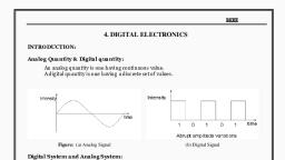
Unit 2, Non conventional Power Generation, Or, Renewable Power Generation, ………………………………………………………………………………………, Syllabus: Solar, Wind, Bio gas and biomass, ocean thermal energy conversion, (OTEC), Tidal, Fuel Cell, Magneto hydro Dynamics (MHD) Schematic, arrangement, advantages and disadvantages of power plants., ………………………………………………………………………………………, Introduction, Energy sources can be divided into two types, Conventional sources of Energy, Non-conventional sources of Energy, What is a conventional source of energy?, • Conventional sources of energy are the natural energy resources which are, present in a limited quantity and are being used for a long time. They are, called non-renewable sources as once they are depleted, they cannot be, generated at the speed which can sustain its consumption rate. They are, formed from decaying matter over hundreds of millions of years., • Examples are coal, petroleum product(like oil petrol, diesel, kerosene),, natural gas, nuclear fuel (like Uranium, thorium, plutonium) and water, resources, • 92 % of electrical energy is generated with the help of coal, petroleum, product , nuclear fuel and natural gas, ., What is nonconventional source of energy?, • Non-conventional sources of energy are the energy sources which are, continuously replenished by natural processes. These cannot be exhausted, easily, can be generated constantly so can be used again and again., • Examples are solar energy, wind energy, tidal energy, biomass energy,, geothermal energy and ocean thermal etc., • They are called renewable resources., • 10 % of electrical energy is generated with the help of renewable energy, sources, , Prof. Mudegaonkar J. L, , KECSP, , Page 1
Page 2 :
Solar Power Plant, The sun releases enormous amount of energy due to continuous fusion, reaction taking place in the sun., The sun sends out this energy in the form of electromagnetic radiations at, the rate of 3.7* 1020 MW. The energy intercepted by the earth is about, 1.85*1011 MW., Though the earth receives large amount of solar energy but its commercial, exploitation is difficult due to following reasons, 1) Its dilute and spread out, 2) Average power available is only 1KW/m2 in hottest area, so large, collection area is needed., 3) The intensity of solar radiations depends upon the weather. In cloudy, days intensity of radiation is very low., 4) This energy source is not available at night., Power generation from solar energy can be done by two ways, Solar thermal power generation: In this plant solar energy is converted in, to heat, heat is converted in to steam, steam energy is converted in to kinetic, energy and finally kinetic energy is converted into electrical energy., Solar photovoltaic power generation: In this plant solar energy is directly, converted into DC electrical energy with the help of solar cells or, photovoltaic cells., Solar Thermal Power Plant:, , Prof. Mudegaonkar J. L, , KECSP, , Page 2
Page 3 :
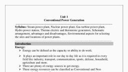
The various components of solar thermal power plant with their functions, are explained below, Collector or reflector: Collector or reflector collects the solar radiation and, concentrate it on single point or line with the help reflection principle., Generally polished glass or aluminized plastic are used as reflectors. Flat,, parabolic and cylindrical type of reflectors is designed as per the temperature, requirement and applications. Due to concentrated light heat energy is produced, which is applied to absorber., Absorber: Absorber is a heating enclosed chamber in which a metallic tube, consists of water is arranged in zigzag manner. Heat generated due to, concentrated solar radiation is applied to absorber so the water in tube converts, in to steam. This steam is applied to turbine., Turbine: steam turbine is a enclosed mechanism in which metallic blades, are fitted on shaft and shaft is free to rotate. When a high pressure steam is, applied on blades kinetic energy is generated in the shaft. Shaft is coupled with, generator., Generator: Generator is an electromechanical machine which converts, mechanical/ rotational energy into electrical energy using a principal faradays, law of electromagnetic induction., Condenser and cooling tower: The exhausted steam from steam turbine is, given to condenser. Condenser is a cooling unit which converts low pressure, steam in to water with the help of cooling tower., Cooling water from cooling tower is circulated in to condenser which, absorbs heat from exhausted steam. The heated water is supplied to the top of, cooling tower & it falls or sprinkles through nozzle for circulation. At the same, time cooled air is circulated or passes from lower side to the top of cooling, tower., Feed Pump: Feed pumps are the water pumps which are used to circulate, the water through water tubes and condenser., , Prof. Mudegaonkar J. L, , KECSP, , Page 3
Page 4 :
Solar photovoltaic Power Plant:, , The various components of solar photovoltaic power plant with their, functions are explained below, Photovoltaic cell array / solar panel: Solar Panel is constructed with the, photovoltaic cell. Photovoltaic cells are semiconductor devices when exposed, in sun light generate voltage. Each photovoltaic cell is having output voltage, about 0.6 volt and current 10 mA. To achieve the battery charging voltage and, current, numbers of solar cells are connected in series and parallel in solar, panel. This solar panel is placed in sunlight which converts light energy into, electrical energy. Output of solar panel is DC energy given to charge controller., Charge Controller: Charge controller is an automatic electronic circuit, whose function is, 1) To supply DC voltage to DC load directly from panel when DC load is, present when sunlight is available., Or, 2) To charge battery directly from panel when DC load is absent when, sunlight is available., Or, 3) To supply DC voltage to DC load from battery when DC load is present, when sunlight is unavailable., Prof. Mudegaonkar J. L, , KECSP, , Page 4
Page 5 :
DC load: It is the electrical or electronic application which operates on DC, supply like bulb, mobile charger, street light LED, DC motor, DC heater etc., Battery: Battery is storing device constructed with the help of chemical, cells. Battery is rechargeable and may be nickel cadmium, lead acid, lithium, ion, lithium ion polymer and lithium metal hydride. When the sunlight is, present battery charges through charge controller and it supplies DC voltage, whenever there is requirement., Inverter: Inverter is an electronic circuit which converts DC supply in to, AC supply. To operate AC applications there is need to convert DC into AC., So inverter is used., Power Transformer: Power transformer converts available AC into, specified AC. So the power requirement of AC application fulfills and it, operates effectively., AC load: It is the electrical or electronic application which operates on AC., Advantages:, 1), 2), 3), 4), 5), 6), 7), 8), , Solar energy is available in ample amount., Solar energy is free. i.e. No fuel cost., It renewable form of energy., It does not cause any pollution., Low operating and maintenance cost., No need of any fossil fuel., Can be installed near load centre so transmission cost reduces., No any type of wastage from this power plant. So no need to waste disposal, plant., Disadvantages:, 1), 2), 3), 4), , Solar energy is available during the day time only., Capital investment is more comparing to output power., Overall efficiency is too much less., Large area solar panels are required to collect solar radiation which, increases the cost., 5) Rainy and cloudy season affects the quantity of power generation., 6) Large storage batteries are required which also increases the cost., , Prof. Mudegaonkar J. L, , KECSP, , Page 5
Page 6 :
Applications of solar energy:, Solar cooker, Solar distribution, Heating and cooling of residential building, Solar drying of agriculture products, Solar system for electric power generation, Solar furnace, Solar photovoltaic cell, Solar green house solar hot water system., Main challenges of solar system, Reducing module cost., Increasing the life time of solar system., Reducing raw material cost., Lowering of capital cost requirement., Optimum solar systems integration, Site selection parameters for solar power plants:, Solar radiation should be available in larger amount for larger, duration., Availability of vacant land should be large as it can be used for future, development of power plant., Transportation facility must be easily available, Distance from the existing transmission line must be less to reduce the, losses., Variation in local temperature and wind speed must be less to improve, the life of photovoltaic cell., Dust in the atmosphere must be less to improve the effectiveness of, photovoltaic cell., Geo technical issues like ground water resistivity, load bearing, capacity, soil pH level etc., Site should be near to military area and historical places., Sites should be plane or slightly tilted are better., Geo political issues., , Prof. Mudegaonkar J. L, , KECSP, , Page 6
Page 7 :
Wind Power Mill, Introduction:, A small portion of total solar radiation reaching on earth’s surface, causes winds due to following reasons, 1) Local wind flow is due to the different heating of land and water in, coastal area. In day period land surface is heated larger as, compared to water surface so hot air moves upward while in the, night period water surface temperature is larger than land surface, so the hot air moves downward., 2) Planetary winds are caused due to the temperature difference, between equator and northern or southern poles., 3) Equator temperature is higher than pole temperature so the hot air, moves towards to poles and low temperature air moves towards, equator., 4) Direction of wind flow depends on rotation of earth., 5) Wind energy is indirect source of solar energy can be used for, generation of power with the help of wind turbine generators., 6) Wind power can be generated where wind velocity are more than 8, KMPH., 7) Wind mills are available along the seacoast and at high altitudes in, hilly terrain., Wind mills are designed in two types, Horizontal axis wind power mill., Vertical axis wind power mill., Horizontal Axis Wind Power Mill/ Turbine (HAWT):, , Prof. Mudegaonkar J. L, , KECSP, , Page 7
Page 8 :
Above fig. shows horizontal axis wind power mill. The various components, of horizontal axis wind power mill with their functions are explained below., Aero turbines or Blades: Blades are mounted symmetrically on horizontal, shaft. Three blades design are preferable as the rotor is naturally balanced. Blades, are made up from glass fiber reinforced plastic to prevent from corrosion., Generally the length of these blades is about 30 feet. These blades are fixed on, shaft with specific tilting angle. The wind energy is converted into mechanical, energy using these blades and shaft is coupled with gear box, Gear Box: Gear box is used to maintain the requirement of speed and torque, when turbines are rotating. Brakes are also provided in this mechanism to control, the speed of turbine. Gear box is coupled with generator., Generator: Generator is an electromechanical machine which converts, mechanical/ rotational energy into electrical energy using a principal faradays law, of electromagnetic induction., Tower: Tower is concrete structure of desirable height. On which the wind, mill is installed., HAWT are designed from capacity 15 KW up to higher capacity, 3MW., The rotational speed of multi blade type wind mills is 60 to 80 rpm., Vertical Axis Wind Power Mill/ Turbine (VAWT):, , Prof. Mudegaonkar J. L, , KECSP, , Page 8
Page 9 :
Above fig. shows vertical axis wind power mill. The various components of, vertical axis wind power mill with their functions are explained below., Aero turbines or Blades: Blades are mounted symmetrically on a vertical, shaft. Blades are made up from glass fiber reinforced plastic to prevent from, corrosion. These blades are fixed on shaft with specific tilting angle. The wind, energy is converted into mechanical energy using these blades and shaft is coupled, with gear box, Gear Box: Gear box is used to maintain the requirement of speed and torque, when turbines are rotating. Electromagnetic brakes are also provided in this, mechanism to control the speed of turbine. Bearing is used to reduce the friction, loss. Gear box is coupled with generator., Generator: Generator is an electromechanical machine which converts, mechanical/ rotational energy into electrical energy using a principal faradays law, of electromagnetic induction., Whole assembly is fixed on foundation and guy ropes are used to keep wind, mill in vertical position, Advantages:, 1), 2), 3), 4), 5), 6), 7), , It is a renewable energy source, It is pollution free power plant, No any kind of waste is generated by this power plant, No need of fuel i.e. no fuel cost., Capital investment is less compare to hydro electric power plant, Can be installed in hilly and non agriculture area, Ideal choice for rural and remote area., , Disadvantages:, 1), 2), 3), 4), 5), 6), 7), 8), , Minimum wind speed required is 8 KMPH, Fluctuation in energy generation due to wind speed, Over all weight is relatively high, Present systems are neither maintenance free nor practically reliable., Large area is required for installation, Large energy storing batteries are required., These wind mills cannot be installed near airports., Tower height is about 90 meters. So transportation of blades, generator, gear, box from ground to tower top becomes a critical task., 9) Noise produces while operating., 10), Massive wind turbines threaten bird species., Prof. Mudegaonkar J. L, , KECSP, , Page 9
Page 10 :
Difference between HAWT and VAWT Generator:, HAWT Generator, It needed yaw control mechanism, , VAWT Generator, It does not need any yaw control, mechanism. This mill can accept the, wind from any direction., It needed support of the nacelle on the It does not need any support of the, top of tower., nacelle on the top of tower as the gear, box brakes, generator are placed on the, ground., Overall cost is large., Overall cost is less, The cost of maintenance is large, The cost of maintenance is less., Design of HAWT generator structure is Design of VAWT generator structure is, complex., easier., Site selection criteria for wind power plant:, Generally four types of sites are considered to be suitable for wind power, plants., 1) Plane land sites, 2) Hill top sites, 3) Sea shore sites, 4) Off shore shallow water sites, There are various factors influencing the location of wind farms as follows, , , , , , , , , , , , , , , , Privately owned free hold land, Population density, Good road access to the sites, Geographical location and regional terrain, Soil condition, Soil erosion and water quality, Altitude of the proposed site, Site expandability, Site geography, Site size, Transmission of power, Land cost., Labour availability., Local ecology., , Prof. Mudegaonkar J. L, , KECSP, , Page 10
Page 11 :
Bio mass and Bio gas, Biomass is the organic matter from plants, animals and micro organism, grown on land and water and their derivates. The energy obtained from biomass is, called biomass energy., Biomass is considered as a renewable source of energy because the organic, matter is generated every day., Coal, petroleum product and natural gases don’t come in the category of, biomass because they are produced from dead, buried biomass under pressure and, temperature during millions of years., Following are the biomass resources, Municipal solids., Sewage wood products, Industrial Waste, Manure at large lots, Crop residues, Logging residues, Disposed manure, Standing biomass, Biomass energy plantation, Bio mass conversion Processes:, The following processes are used to convert biomass energy into bio fuels., 1) Pre- Processing: It involves pelletization and torrefaction., In pelletization dry biomass are crushed to form small pieces. So the, biomass becomes solid fuel which can be used for combustion. e.g., wood, cereals, cellulose biomass etc., In torrefaction, water contains available in bio mass are removed by, applying temperature 200 to 300°C. So the biomass energy density, increases., 2) Combustion or co firing:, Here biomass is burn in the absence of oxygen to produce heat., Dry biomass is mostly used. It is used to produce electric power when, used to generate heat., , Prof. Mudegaonkar J. L, , KECSP, , Page 11
Page 12 :
3) Chemical method:, It involves transeterification and hydrogenation. In transeterification,, alcohol is mixed with vegetable oil to produce fatty acid allcylester., Vegetable oil includes soya oil, palm oil, waste oil from cooking etc., are used. Alkyl ester oil is used as a transport fuel in ignition engines., In hydrogenation, hydrogen is added in vegetable oil to produce, hydrocarbon chains. It can be used as a transport fuel in ignition, engines., 4) Biological method: It involves two main methods., 1) Hydrolysis and fermentation: In this method sugars are fermented with, products like ethanol, starch based plant stack to get oil., 2) Lingo-Cellulosic hydrolysis and fermentation: In this method, pretreated, carbohydrates are converted to alcohol based fuels. Generally cellulose, biomass is used. It is used as a transport fuels., 5) Thermo- chemical Methods: It involves gasification and pyrolysis method., 1) In gasification method,, at high temperatures about 700°C to 1200°C, biomass is converted, into ‘syngas’ in the absences of oxygen. Here cellulose biomass is, used., The syngas is burn to produce heat and electric power., The syngas can be converted into liquid fuel by catalysis method., In liquid state it can be used as transportation fuel., 2) In pyrolysis method,, At high temperature 45°C to 550°C biomass is converted into, bio oil of light syngas in the absences of oxygen. Here any, biomass waste can be used., Pyrolysis oil can be used as transport oil. Even it can be burn to, produce heat and electric power., 6) Anaerobic Digestion:, Here the microbes’ breakdown the solid biomass into methane and, CO2., Green crops, manures, sewage and food waster are used as biomass to, generate biogas., By burning methane gas we can generate heat and electric power., It can be processed to use as a transport fuel., , Prof. Mudegaonkar J. L, , KECSP, , Page 12
Page 13 :
Biomass and Biogas power plant, Bio, mass, and, bio, gas, , Combusti, on, Chamber, , Nozzle, , Steam, Turbine, , Generator, , Boiler, , Electrical Energy, , Air, , water, , Fig: Block diagram of bio mass and bio gas power plant, Above figure shows the block diagram of biomass and bio gas power plant. The, working of biomass and biogas power plant is similar to steam power plant only, the change is biomass and bio gas is used as a fuel instead of coal. The various, component of this power plant are as follows., Combustion Chamber: Combustion chamber is enclosed chamber where biomass, and biogas is burned to produce heat or thermal energy. This thermal energy is, given to boiler., Boiler: Boiler is cylindrical shaped metallic enclosure which consists of furnace,, water tube assembly, economizer, super heater, pre heater and chimney. Outer, shell of boiler is coated with thermal resistive material to improve the efficiency, and to protect the workers from the heat. In this section water is converted into, high temperature steam. Now this steam is given to nozzle., Nozzle: Nozzle is a mechanical device whose out let diameter is too much small, compare to inlet diameter. Due to this device high temperature steam is converted, into high pressure steam. Now this steam is applied to steam turbine., Steam turbine: steam turbine is a closed mechanism in which metallic blades are, fitted on shaft and shaft is free to rotate. When a high pressure steam is applied on, blades kinetic energy is generated in the shaft. Shaft is coupled with generator., Generator: Generator is an electromechanical machine which converts, mechanical/ rotational energy into electrical energy using a principal faradays law, of electromagnetic induction., Prof. Mudegaonkar J. L, , KECSP, , Page 13
Page 14 :
Generation of biogas using ‘Janta Model Gobar Gas plant’:, The main sources of production of biogas are cow dung, sewage, crop, residues, vegetable waste, water hyacinth, alga, poultry dropping, pig, manure, ocean kelp etc., Biogas, a mixture containing 55-60% of methane and 40-45%of, carbon dioxide and some impurities like hydrogen sulfide and, nitrogen., It can be produced from the decomposition of animal, plant and, human waste., It is clean and slow burning gas usually has a heating valve about, 18KJ/m3., It can used directly in cooking, domestic lighting, heating and IC, engines., Biogas plant converts wet biomass into biomass by the process of, fermentation., The bacteria called anaerobe carries out digestion of bio mass, without oxygen and produces methane and carbon dioxide., , Prof. Mudegaonkar J. L, , KECSP, , Page 14
Page 15 :
Above figure shows the Janta Model Gobar Gas Plant whose various, components are as follows, Foundation: the foundation is the amply compacted base of the digester, made up of cement concrete and brick ballast. Its construction is so carried out, that, it may provide stable foundation to digester walls. It should be water proof so, that no percolation or leakage takes place., Digester: it is the underground cylindrical wall portion of bricks sand and, cement. The fermentation of dung takes place in the digester. Sometimes it is also, called as fermentation tank. Two rectangular opening facing opposite each other, are provided for inflow and out flow at almost middle of its height., Dome: It is a hemispherical roof of the digester has at fixed height and, forms the critical part in the construction of Janata Gobar Gas Plant. The gas gets, collected in the space of dome and exerts pressure on the slurry in the digester., Inlet Chamber: An inlet chamber has a bell mouth shape is made of bricks, cement and sand. It has its top opening at the ground level. It’s out let wall is made, inclined to enable the daily cattle dung feed to move easily into digester., Outlet Chamber: It is the part of plant through which digested slurry moves, out of the digester at predetermined height. It has a small rectangular cross section, and above this it becomes larger to a defined height. For easy cleaning two steps, are provided in it to climb down., Mixing tank: In this tank where gobar and water are mixed properly in the, ratio 1:1 to make slurry which is then poured into the inlet chamber., Gas outlet pipe: It is small piece of GI pipe which is fitted at the top of the, dome for conveying the gas to the points of use. A valve is fitted at its end to, regulate the flow of gas., Advantages:, , , , , , No maintenance problem due to absence of moving part., Low cost, Low operating cost, Longer working life, , Prof. Mudegaonkar J. L, , KECSP, , Page 15
Page 16 :
Underground construction, No danger of explosion, No gas leakage, Plants can located near to remote area, It produces manure which can be used as fertilizer, House hold and bio waste can be utilized for power generation, Disadvantages:, Variable gas pressure, Problem of scum formation, For construction skilled mason is required., It is not feasible for large scale power generation, Efficiency is less, It is not suitable to place everywhere, Biogas has some impurities which can create corrosion problem, Site selection criteria for bio mass power plant:, , , , , , , , , , Availability of fuel, Distance of load centre, Land availability and its cost, Transport facility, Geology and soil type, Pollution, Ash disposal facility, Political support, , Ocean Thermal Energy Conversion (OTEC), The ocean covers about 70% of the global surface and particularly extensive, in the tropical zone, therefore most of the sun radiations are absorbed by sea, water., The ocean surface water temperature is about 28 to 25 °C in day time., The temperature of the water at depth of 1000m in the ocean is 5 to 6°C., OTEC is the concept through which we can generate electricity using the, temperature difference of surface warm water and cold depth water of ocean., The schematic diagram for OTEC is as shown below, , Prof. Mudegaonkar J. L, , KECSP, , Page 16
Page 17 :
Generally these systems are located offshore of large floating platforms or inside, the hull (ship). The various components of OTEC power plant are as follows, Evaporator: Evaporator is similar to heat exchanger of nuclear power plant., This is an enclosed chamber in which warm water from the surface of ocean, vaporize the working fluid whose vaporization point is less than25°C like propane, or ammonia. Vaporized gas is high pressure gas which is given to turbine through, nozzle., Turbine: Turbine is a closed mechanism in which metallic blades are fitted, on shaft and shaft is free to rotate. When a high pressure gas is applied on blades, kinetic energy is generated in the shaft. Shaft is coupled with generator., Generator: Generator is an electromechanical machine which converts, mechanical/ rotational energy into electrical energy using a principal faradays law, of electromagnetic induction., Condenser: The exhausted gas from turbine is given to condenser., Condenser is a cooling unit which converts low pressure gas in to liquid with the, help of cold water fetched from 1000 m depth of ocean., Feed Pump: Feed pumps are the water pumps which are used to circulate the, water in evaporator and condenser. Also the working fluid circulating pump is used, to circulate ammonia or propane liquid through evaporator, , Prof. Mudegaonkar J. L, , KECSP, , Page 17
Page 18 :
Advantages:, It is the clean from of energy generation, It does not occupy land areas, It is the steady source of energy as the temperatures are almost steady., No Fuel cost., No any kind of pollution., Disadvantages:, About 30% of power generated is used for pumping water., System may damage due to hurricane , presence of debris and hazards from, fishes., Corrosion on Metallic parts, Construction is difficult for floating power plants, Heavy investment, Low efficiency, Less amount of power generation, Fish migration can be affected, Site selection parameters for OTEC, , , , , , , , , , Nearness to coast, Water shallower, High flow speed, Stable speed velocity, Chosen sites, Wave curve form, Availability of labours, Cost and availability of shore line sites, , Tidal Power Plant, Tidal power generation is also called lunar power generation., Tides are due to the combined gravitational forces of sun and moon on the, waters of the earth., When the gravitational force of sun and moon are added together they give, rise to maximum tide called as spring tide., When the gravitational force of sun and moon opposes each other they give, rise to minimum tide called as neap tide., In one year nearly 705 full tide cycles are seen., , Prof. Mudegaonkar J. L, , KECSP, , Page 18
Page 19 :
Tidal energy is the renewable energy which is unlimited source of energy in, the ocean., The potential energy of the water (water level of sea and basin) can be, converted into Electrical energy using tidal power plant., Above figure shows schematic diagram of the tidal power plant for high and, low tide. The various components of tidal power plant are as follows., Dam or Dyke: This is the small wall build to trap the sea water behind it. Or, we can say that the dam or dyke is the barrier which separates sea and basin., Turbine / turbo generator:, Turbo generator is the combination of turbine and reversible electric, generator., Turbo generator is fixed in dam wall with both side openings i.e., gates., At the time of high tide, water level of ocean is more than water level, of basin so water flows from ocean to basin and electricity is, generated., At the time of low tide, water level of ocean is less than water level of, basin so water flows from basin to ocean and electricity is generated., Prof. Mudegaonkar J. L, , KECSP, , Page 19
Page 20 :
Power house: Power house consist of auxiliary components of power, generator, controlling equipments, gate drivers and transmission line devices, like cables, wires and transformers etc., Advantages:, Tidal power is independent on rain fall., It is renewable and sustainable energy source., It decreases the dependence of fossil for electrical energy., Larger efficiency, Long life, Better efficiency, System is easy to operate and maintain., Valuable land is not required., It can be used in combination with hydro electric power plants., Power generation is free from pollution., No fuel cost., Disadvantages:, , , , , , , Due to variation in tidal range the output is not uniform., Corrosion in machinery takes place due to sea water., Difficult to construct dyke or dam in the sea., Sedimentation and siltation causes problem in basin., Power transmission cost is high., , Fuel cell, It produces electricity by a chemical reaction without any combustion., Major difference between fuel cell and battery is that, fuel cell have, continuous energy input and output while in case of battery, it stores charge., In the construction of fuel cell, two electrodes are used one is called as, anode and other is called as cathode. These two electrodes are placed in, electrolyte solution in the container. These electrodes are sealed at the top of, container and container having opening to fuel in and waste out., Following are the different types of fuel cell, 1) Alkaline Fuel cell (AFC), 2) Phosphoric acid fuel cell (PAFC), 3) Molten carbonate Fuel cell (MCFC), 4) Proton Exchange Membrane Fuel cell (PEMFC), 5) Solid Oxide Fuel Cell (SOFC), Prof. Mudegaonkar J. L, , KECSP, , Page 20
Page 21 :
Alkaline Fuel cell (AFC):, , AFCs are invented by Francis Thoma Bacon in 1959.it consist of two porous, carbon electrodes with catalyst like Pt , Ag, C2O etc., It uses KOH and NaOH as electrolyte. H2 and O2 gases are released into, electrolyte with the help of porous carbon electrodes., It provides near 0.9 volt., Chemical reaction at anode, H2, 2H+ + 2e Chemical reaction at anode, ½ O2 + H2O+ 2e20 H In electrolyte, H2 + ½ O2, H2O, In this cells the oxidation i.e. loss of electrons takes place on anode and, reduction i.e. gain of electrons takes place on cathode., Advantages:, , , , , , , , , , Conversion efficiencies are very high., Requires little attention and less maintenance., Can be installed near the use point., It does not make any noise, A little time is required to go into operation., Less space is required., No cooling water is required, Capacity up gradation can be done., , Prof. Mudegaonkar J. L, , KECSP, , Page 21
Page 22 :
Disadvantages:, High initial cost, Low service life., Magneto Hydro Dynamics, , Magneto hydro dynamics name is concerned with flow of conducting fluid, in the presence of magnetic and electrical field., The fluid may be gas at elevated temperature or liquid like sodium or, potassium., In MHD, ionized gas or plasmsa is acting as moving conductor in magnetic, field due to which the voltage is generated., The working principal of MHD is faradays law of electromagnetic induction., “When conductor is placed in changing magnetic field an emf induces in it”., In MHD Solid conductor is replaced with gases conductor i.e. ionized gas., Following fig shows MHD generator., , The various components of MHD generator are as follows,, Pre heater: Pre heater is the first stage of heating in which compressed, oxygen is heated up to 1100°C and feed to combustion chamber for post heating., Combustion chamber: Combustion chamber is the second stage of heating, in which pre heated oxygen is post heated up to 2300°C by burning the fuel. The, ionization of oxygen takes place so it becomes conductive gas. To increase the, conductivity, material like potassium carbonate is injected in ionized gas (plasma), now this plasma is passed through nozzle., Prof. Mudegaonkar J. L, , KECSP, , Page 22
Page 23 :
Nozzle: Nozzle is a metallic part whose inlet diameter is large compare to, outlet diameter. Nozzle is used to increase the velocity of plasma and then passed, through magnetic field of MHD generator., MHD generator: MHD generator consists of powerful magnets. When high, pressure, high temperature, conductive ionized gas passes through magnetic field ,, an emf induces. The positive charges are collected by anode and negative charges, are collected by cathode so the DC power is generated. Water cooling method is, used to cool the MHD duct., Inverter: Inverter is the electronic circuit which coverts stored DC into AC, so that the ac applications can operates., Seed recovery unit: Seed recovery unit recovers the potassium carbonate, from the exhausted gas so that it can be again used for next cycles. Potassium, carbonate free exhausted gas is feed to pollution control unit., Pollution control unit: Pollution control unit extracts carbon dioxide,, oxides of nitrogen, and oxides of sulfur from the exhausted gas of MHD and, finally released in the air., Advantages:, Conversion efficiency is high about 60 to 65 %., Less wear and tear due to no moving parts in the generator., Less pollution compare to other power plants., Instant operation., MHD generator is compact having less weight., Less operating cost., Disadvantages:, Power generation is directly Proportional to square of magnetic field so high, power magnets are required which increases the cost., Life of power plant is less because of chemical erosion and corrosion at high, temperature and high pressure., MHD generator must be capable to handle high temperature so design cost, increases, High temperature around 2500°C is required to ionize the gas., About 12% losses are of thermal and frictional in these power plants., Questions, 1. Draw the schematic diagram of solar thermal power plant and explain it and, list advantages and disadvantages.( Dec 11,Oct 17, may 18), 2. Draw the schematic diagram of solar photovoltaic power plant and explain it, and list advantages and disadvantages.( May 15), Prof. Mudegaonkar J. L, , KECSP, , Page 23
Page 24 :
3. List the application of solar energy.( Oct 17), 4. Draw schematic diagram of wind power plant, explain any one wind power, mill with its advantages and disadvantages.(Nov 16 Dec 17), 5. Compare between solar and wind power plant ( May15), 6. What are the sources of biomass and biogas.( NOV 16), 7. What the technologies used to convert biomass into biogas.(DEC17), 8. Draw and explain biomass and bio gas power plant with its advantages and, disadvantages, 9. Write detail note on Ocean Thermal Energy Conversion, 10.How electricity is generated with the help of tidal power plant? Explain in, detail with advantages and disadvantages ( Dec 11, May 18), 11.Write a short note on fuel cell. (Oct 17), 12.Draw and explain the concept of magneto hydrodynamics with its, advantages and disadvantages ( May 15, Oct 17), , Prof. Mudegaonkar J. L, , KECSP, , Page 24