Page 1 :
CHAPTER, , lo, , AC. TRANSIENTS, , , , , , , , , , , , , , , , INTRODUCTION, , previous unit, we have obtained the transient response of RL, RC and RLC circuit by, ¢ differential equations with d.c voltages. The first part of the solution with forcing, x 0 to zero (Homogeneous part of the differential equations) gives the transient response, stich solely depends on the network elements and their connection. This is independent of the, acting in the circuit., this unit, the transient response of the above circuits with a.c sinusoidal voltages is being, . The types of sources acting in the circuit mainly influence the steady state part of the, 1. The general procedures to determine the particular integral are presented., , , , 12] RL CIRCUIT, , _ Gonsider a series RL circuit shown in Fig. 16.2.1 in which the switch S is closed at = 0., , , , <a, , FIGURE 16.2.1:, , Since there was no current in the circuit prior to closing the switch and because of the, , uctor the current will be zero immediately after closing the switch., , eats, , , , , ek At EE I =0 and hence, Ba peo? i (0*) =0 (since inductance is present in the circuit)... (16.2.1), , o By applying KVL to the circuit for all 120, n+ LG = Vp sin(or+0) -.. (16.2.2), i G, di -R; _- —™sin(@t+0, ae Om, NETWORK THEORY, , , , A
Page 2 :
16-2 WM AC TRANSIENTS, , / V., (>+7}: = T sin (wrt), , The complementary function of the above D.E 1s, , Lh, le =Ae L (16.2.3, , (This gives the transient part of the solution)., , The steady state solution of equation (16.2.2) can be obtained by one of the following, methods,, , Method 1;, , , , The steady state solution has the same mathematical form of the excitation plus its derivatives, and its first integral. The particular integral or steady state part of the solution corresponding to the, sinusoidal excitation can be taken as, , ip =Acos(@r+0)+Bsin(wr+0) (16.2.4), , Where 4 and B are constants whose values depend on Ve ,@ and R and L of the circuit, Substituting the tral solution of Equation (16.2.2) in Equation (16.2.2)., R(Acos(@6+8)+Bsin(w1+0)+Ll(-Awsin(@r+0)+Bacos(wr+8)), , , , =V,,sin(@r+6), , (R4 + @ LB) cos(m1+0) + (RB-wLA)sin(@r+O)=V, sin(@r+O).. (16.2.5), , Equating the corresponding coefficients of sine and cosine terms on either side of equation, (16.2.5), we get,, , , , , (RA+@LB) =0, (RB-@LA) = V,,, , , , , ol, A =-——-.B, R, 272, oa Ll, [eo + R a)-¥,, , 2 tt, B(R +l’) _y, , R m, , , , VER, , m, , R +071?, , , , , , , , , , , Be, , , , as -V,, OL, R402, , , , NETWORK THEORY
Page 3 :
wy ORCUTT AC. TRANSIENTS Mal 16 - 3, , The steady state solution is given by, v, , m, , ‘a Fi te [Rsin(wr+0)-wLcos(wl+9)] .»» (16.2.6), , The above expression can be written as single sinusoidal function with phase angle a., , The equation (16.2.6) can be written as, , , , Vv:, m R, es ee, es es wo Le OLE picatie TatL sin(@r+0), ol, SSS “08 (01 + 8) ++ (16.2.7), VR? + w Le, From the impedance triangle of the circuit shown in Fig. 16.2.2, we get, R, cos 8 =, VR? +0" L, tid see 2, VR? + o LD, Hence equation (16.2.7) reduces to R, y FIGURE 16.2.2:, : m, i. = (cos a sin(o1+6)-sinacos(@1+8, = RoE ae meee, V, , ... (16.2.8), , m :, "Raat sin(@1+6-a), , Where a = tan”! ot = impedance angle of the circuit., , V, The equation (16.2.8) is similar to _ sin (@ f+ 8 - a ) which is same as steady state value, , of current in a RL circuit., , v, i,,= 7" sin (4+ 0 — a.) lags the voltage by angle a., , , , Method 2 :, , From equation (16.2.2) we get, y,, sin (or+0), , R, i(o+4), 2, , Steady state solution is obtained by putting D?=-«?., , es (16.2.9), , 1=, , NETWORK THEORY
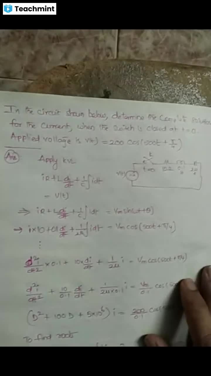
Page 4 :
16-4 MMM AC TRANSIENTS RL Cincom,, Muluplying the numerator and Denominator by [i - >| we get, (R_p\y si 8, (zo m Sin (@r+0), :~ 2, R 2, 8-9) lee, ¥., , ————41— (Z->} sin(@r+0), , 2, ‘6:5, Vink R, a a [Zsinor+0)- 0 cos(wr+9), , (R? +07 17) (2, m, =a 575 (Rsin(@r+8)-wLlcos(wr+0, Rol? u, , The above equation is same as that of equation (16.2.6) and can be reduced as equation, (16.2.8)., , The complete solution is, , eo RVL, , V, i=A + Tisin(@1+0-a) .. (16.2.10), , The constant A is to be evaluated using initial condition i.e., i (0* )=0 in Equation (16.2.10), 4, 0 =A+—™ sin (0-a), , Vy, A = sin(0- a), , .. The complete solution is, , —RVL a, , Vv., i() = -Fsin(O-a)e + sin (@1+0-a), , V, = [sin(@1+O-a)-sin(@-a)ye Fy (16.211), , In equation (16.2.11), the first part gives the steady state part of the current which is sinusoidal, , -10L, and lagging the voltage by angle a = tan ! vs The second part contains e * which goes to zero, , V, . . . m.. ina short time. The transient part is (- = pin (8-a ) e7 Rt and the value of transient component, , depend on 0, whose value depends upon the point on the waveform at which the switch 1s closed, and can take any value from 0 to 2 7., , , , NETWORK THEORY
Page 5 :
so omcuiT AC. TRANSIENTS Ml 16 - 5, , If@-a=n7, wheren=0,1,2,3.... then the constant is zero and the current directly, oes lo steady state (no transient will exist)., , . 1 V, 3, If(0-a) =(1 + 2n) 77 the transient will have the max. amplitude of -—. Hence the transient, z, part of the solution depends on the point on the waveform of voltage at which the switch is closed., It will not have any transient if the switch is closed corresponding to a point., , Where @ = (nm +0) form =0, 1, 2,3... or will have max. transient if the switch is closed, corresponding to a point where, , 8 =(2n41) 5to, , where & = impedance angle , = tan”! ©@4,, , If the circuit is highly inductive (such as a transformer). a = 90°. such that if the circuit is, energised on the voltage wave at 0 =F then there is no transient. (near about peak value). If the, , cmeuit is energised on the voltage wave when it is closer to @ = 0 i.e., zero value, the transient will, save maximum amplitude. The transient will depend on the instantaneous value of the voltage at, ze mstant when the switch is closed., , , , 16.3 | RC CIRCUIT, , Consider a series RC circuit shown in fig. 16.3.1 in which switch S is closed at t= 0. The, 2pacitor is initially uncharged., , v() = Vim sin (wt+ 8), , , , , , , , FIGURE16.3.1 :, Att=0 = ve (0) =0 hence, atr=0* ye(0*) =0, By KVL for all 2 0 we get, iR+> fiat = Vv, sin(wr+8) -.. (163.1), Differentiating with respect to time and putting £ =D, we get, pe); 2 9, ( ae) R cos(@1+6) ... (16.3.2), , , , NETWORK THEORY
 Learn better on this topic