Page 1 :
Unit 2: Measurement of Electrical Quantities, ================================================================, Syllabus:, Measurement of Voltage, Current, and Power; Measurement of 3 phase power; Study of, Energy meters. Study of Electrical Storage devices: Batteries such as Nickel-cadmium, (Ni Cd), Lithium- ion (Li-ion), Lithium Polymer (Li-pol.) batteries. Study of circuit, breakers & Actuators (MCB & MPCB, Power Contactors & Aux contactors, ElectroMechanical & Solid state Relays), =================================================================, What is Voltmeter?, Voltmeter is used to measure voltage. Voltage is the Potential difference between any, two point/ Nodes of an Electric circuit. We know the unit of potential difference is volts. So, the Electrical instrument which measures the voltage is called Voltmeter., Classification or Types of Voltmeter: Voltmeters are broadly classified as DC Voltmeter, and AC Voltmeter. Voltmeters can be constructed using different principals so according to, construction, voltmeter having following types, 1., 2., 3., 4., 5., 6., 7., , Permanent Magnet Moving coil (PMMC) Voltmeter., Moving Iron (MI) Voltmeter., Electro Dynamometer Type Voltmeter., Rectifier Type Voltmeter, Induction Type Voltmeter., Electrostatic Type Voltmeter., Digital Voltmeter (DVM)., , ., PMMC Voltmeter, , Working Principle of PMMC is, “When current carrying conductor is placed in a, magnetic field, a mechanical force experiences on conductor”, Fleming left hand rule gives the direction of experienced force. Fleming‟s left hand, rule states that, “stretch your first finger, middle figure and thumb of left hand in such way, that they becomes mutually perpendicular to each other, If the first figure shows the direction, of magnetic flux density, middle figure shows the direction of current then thumb shows the, direction of mechanical force”., Construction of PMMC: A permanent magnet with horse shoe pole pieces is used to, concentrate the magnetic field in the annular cavity. The coil wounded on iron core is placed, in this cavity which can free to rotate. A pointer is attached to coil and initially the pointer
Page 2 :
position is at zero. The spring and balance weight attached at other side of coil keeps the, pointer at zero when no current is flowing through coil, Working of PMMC: when the current flows through the coil, mechanical force, experiences on the coil so we get deflection of pointer over the scale. The deflection of the, pointer is directly proportional to the current flowing through coil. By calibrating the, instrument we can measure the voltage accurately., Deflecting Torque=B*I*N*l Nm, Where,, B = Flux density in Wb/m2., I = current flowing through coil in A., l = Length of the coil in m., N = No of turns in the coil., It is used for DC measurement because here deflection is proportional to the voltage, because resistance of the coil is constant. If voltage polarity is reversed, deflection of the, pointer will also be reversed. This type of instrument is called D‟Arsonal type instrument., The advantages of these meters are linear scale, power consumption is low, high accuracy., Major disadvantages are it measures only DC quantity, and have higher cost., , What is an Ammeter?, “A device or instrument which is used to measure the current is called the ammeter”., Current is rate of change of charges or we can say that, current is flow of charges. The unit, of the current is ampere., , PMMC can detect only small currents, so to measure large currents PMMC is, converted into an ammeter by connecting a low resistance in parallel with coil. This parallel, resistance called shunt resistance., What is an Ohmmeter?, “An ohmmeter is an instrument which measures the resistance of the electrical circuit, between any two points”, Ohmmeter Working Principle, The construction of ohmmeter is shown in the following figure in which battery and, the PMMC is connected in series and the remaining ends of battery and PMMC are acting as, test leads., When test leads are shorted, maximum current flows through meter and we get Full, deflection on the scale and this full deflection is nothing but the zero resistance value.
Page 3 :
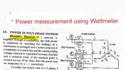
When a resistance which is to be measured is connected between tests terminals,, current flowing through coil is depends on the resistance value we get the deflection on the, scale. By calibrating this instrument for different standard resistance values we can plot the, scale and with the help of this scale we can measure the unknown resistance., , In the ohmmeter is observed that, the zero resistance marking is at extreme right hand, and high value resistance marking is at extreme left hand ( i.e. reverse scale), Multi meter (Digital/ Analog), Multimeter is an integrated instrument which can be used for the measurement of different, electrical parameters. In digital multimeter the measured value is in the form of digits. In, Analog meters the measured value is in the form of pointer and scale., Multimeter is generally used to measure AC voltage, DC voltage, AC current, DC, current, Resistance and continuity test. But in advance meter some additional parameter, measurement is also included such as Diode Test, Frequency, Gain of the Transistor,, temperature etc., , Wattmeter, A Device designed for measurement of AC or DC power is called Wattmeter, The Unit of Electric Power is Watt., DC Power is the product of voltage and current, There are three types of watt meter, Dynamometer type Wattmeter, Induction type Wattmeter, Electrostatic type Wattmeter
Page 4 :
Dynamometer type single phase Wattmeter, Dynamometer type Wattmeter is basically moving coil instruments., In this wattmeter has two coils are used. One is moving coil (current coil) and other is, fixed coil (Voltage coil)., The operating field is produced by the fix coil instead of permanent magnet., Dynamometer type wattmeter is very important because they are commonly used for, measuring power in ac circuits., Working: The basic working principle of Dynamometer type wattmeter is that, when, the current flows through fixed coil, fixed coil produces magnetic field, now the current, carrying moving coil is in this magnetic field, on which force is exerted and we get, deflection. The deflection torque is due to voltage coil (fixed coil) and current coil (moving, coil) which reflects the power., , Dynamometer type Three phase wattmeter, A dynamometer type three-phase wattmeter consists of two separate wattmeter, movements mounted together in one case with the two moving coils mounted on the, same spindle. The arrangement is shown in Fig., There are two current coils and two voltage coils. i. e. two single phase watt meters, are used. Each watt meter is called as element., The connection diagram of a 3 phase wattmeter using two watt meters is shown in the, following figure, The torque on each element is proportional to the power being measured by it., The total torque deflecting the moving system is the sum of the deflecting torque of‟, the two elements., Hence the total deflecting torque on the moving system is proportional to the total, Power., In order that a 3 phase wattmeter read correctly, there should not be any mutual, interference between the two elements., A laminated iron shield may be placed between the two elements to eliminate the, mutual effects
Page 5 :
Energy Meters and Their Working Principles:, Energy Meter or “Watt-Hour Meter” is an electrical instrument that measures the, amount of electrical energy used by the consumers., This meter is placed at every place like homes, industries, organizations, commercial, buildings to read the electricity consumption., , The basic unit of power is watts and it is measured by using a watt meter. One, thousand watts make one kilowatt., If any consumer uses one kilowatt in one-hour duration, one unit of energy gets, consumed (i.e. 1000wH energy is consumed), Types of Energy Meters, The energy meters are classified into two basic categories, such as:, Electromechanical Type Induction Meter, Electronic Energy Meter, Single Phase Electromechanical Induction Energy Meter, , It is a well-known and most common type of age-old energy meter., It comprises a rotating aluminium disc placed on a spindle between two, electromagnets., The rotation speed of the disc is proportional to the power, and this power is, integrated by the use of gear trains and counter mechanism., Braking magnet is a kind of permanent magnet that applies the force opposite to the, normal disc rotation to move that disc a balanced position and to stop the disc while, power gets off.
Page 6 :
What is a Battery?, A Battery is a device consisting of one or more electrical cells that convert chemical energy, into electrical energy. Every battery is basically a galvanic cell where redox reactions take, place between two electrodes which act as the source of the chemical energy., Battery types, Batteries can be broadly divided into two major types., Primary Cell / Primary battery, Secondary Cell / Secondary battery, , These are batteries where the redox reactions proceed in only one direction. The reactants in, these batteries are consumed after a certain period of time, rendering them dead. A primary, battery cannot be used once the chemicals inside it are exhausted., An example of a primary battery is the dry cell – the household battery that commonly used, to power TV remotes, clocks, and other devices. In such cells, a zinc container acts as the, anode and a carbon rod acts as the cathode. A powdered mixture of manganese dioxide and, carbon is placed around the cathode. The space left in between the container and the rod are, filled with a moist paste of ammonium chloride and zinc chloride., The redox reaction that takes place in these cells is:, At Anode, Zn(s) –> Zn2+ (aq) + 2e–, At Cathode, 2e– + 2 NH4+ (aq) –> 2 NH3 (g) + H2 (g), 2 NH3 (g) +Zn2+ (aq) –> [Zn (NH3)2] 2+ (aq), H2 (g) + 2 MnO2 (S) –> Mn2O3 (S) + H2O (l), Thus, the overall cell equation is:, Zn(s) + 2 NH4+ (aq) + 2 MnO2 (S) –> [Zn(NH3)2] 2+ (aq) + Mn2O3 (S) + H2O (l), Another example of the primary cell is the mercury cell, where a zinc-mercury amalgam is, used as an anode and carbon is used as a cathode. A paste of HgO is used as an electrolyte., These cells are used only in devices that require a relatively low supply of electric current, (such as hearing aids and watches)., Secondary Cell, These are batteries that can be recharged after use by passing current through the electrodes, in the opposite direction, i.e. from the negative terminal to the positive terminal.
Page 7 :
For example, a lead storage battery that is used in automobiles and inverters can be recharged, a limited number of times. The lead storage battery consists of a lead anode and the cathode, is a lead grid packed with lead dioxide. Sulphuric acid with a concentration of 38% is used as, an electrolyte. The oxidation and reduction reactions involved in this process are listed, below., At Anode, Pb –> Pb2++ 2 e–, Pb+ SO42– –>PbSO4(electrode) + 2 e–, At Cathode, 2 e–+ PbO2+ 4 H+ –> Pb2++ 2 H2O, 2 e–+ PbO2+ 4 H++ SO42- –> PbSO4(electrode) + 2 H2O, In order to recharge these batteries, the charge is transferred in the opposite direction and the, reaction is reversed, thus converting PbSO4 back to Pb and PbO2., Another example of the secondary cell is the nickel-cadmium cell. These cells have high, storage capacities and their lifespan is relatively long (compared to other secondary cells)., However, they are difficult to manufacture and maintain., Comparison between different types of battery, NiMH, , Lead Acid, , Li-ion, , Li-ion polymer Reusable, Alkaline, , NiCd, Gravimetric Energy, Density(Wh/kg), , 45-80, , 60-120, , 30-50, , 110-160, , 100-130, , 80 (initial), , Internal Resistance, , 100 to 2001, 6V pack, , 200 to 3001, 6V pack, , <1001, 12V pack, , 150 to 2501, 7.2V pack, , 200 to 3001, 7.2V pack, , 200 to 20001, 6V pack, , 15002, , 300 to 5002,3, , 200 to, 3002, , 500 to 10003, , 300 to, 500, , 503, (to 50%), , Fast Charge Time, , 1h typical, , 2-4h, , 8-16h, , 2-4h, , 2-4h, , 2-3h, , Overcharge Tolerance, , moderate, , low, , high, , very low, , low, , Self-discharge /, Month (room temperature), , 4, , 20%, , 30%, , 5%, , 10%, , ~10%, , Cell Voltage(nominal), , 1.25V6, , 1.25V6, , 2V, , 3.6V, , 3.6V, , 1.5V, , 20C, 1C, , 5C, 0.5C or lower, , 5C7, 0.2C, , >2C, 1C or lower, , >2C, 1C or lower, , 0.5C, 0.2C or lower, , (includes peripheral circuits) in, mΩ, , Cycle Life (to 80% of initial, capacity), , 4, , Load Current, -, , peak, best result, , 5, , moderate, 5, , 0.3%
Page 8 :
NiMH, , Lead Acid, , Li-ion, , Li-ion polymer Reusable, Alkaline, , -40 to, 60°C, , -20 to, 60°C, , -20 to, 60°C, , -20 to, 60°C, , 0 to, 60°C, , 0 to, 65°C, , Maintenance, Requirement, , 30 to 60 days, , 60 to 90 days, , 3 to 6 months9, , not req., , not req., , not req., , Typical Battery Cost, (US$, reference only), , $50, (7.2V), , $60, (7.2V), , $25, (6V), , $100, (7.2V), , $100, (7.2V), , $5, (9V), , Cost per Cycle(US$)11, , $0.04, , $0.12, , $0.10, , $0.14, , $0.29, , $0.10-0.50, , Commercial use since, , 1950, , 1990, , 1970 (sealed, lead acid), , 1991, , 1999, , 1992, , NiCd, Operating, Temperature(discharge, only), , Study of power contractors /circuit breakers (MCB & MPCB), A Miniature Circuit Breaker is an electromechanical device designed to protect an, electric circuit from over-current / overload /short circuit. Back in the day we protected, against over-current by using fuse wire The principle was fairly simple - an overcurrent would quite literally, 'blow' the fuse wire by rapidly heating and melting it, thus, breaking the electrical connection and in doing so, protected the rest of the electrical circuit., , Working & Operation of MCB, Under normal working conditions, MCB operates as a switch to make the circuit ON, or OFF., Under overload or short circuit condition, it automatically operates or trips so that, current interruption takes place in the load circuit., The visual indication of this trip can be observed by automatic movement of the, operating knob to OFF position., This automatic operation MCB can be obtained in two ways as we have seen in MCB, construction; those are magnetic tripping and thermal tripping.
Page 9 :
In thermal tripping: Under overload condition, the current through the bimetal, causes to raise the temperature of it. The heat generated within the bimetal itself, enough to cause deflection due to thermal expansion of metals. This deflection further, releases the trip latch and hence contacts get separated. In some MCBs, magnetic field, generated by the coil causes develop pull on bimetal such that it deflection activates, the tripping mechanism., , Magnetic tripping: Under short circuit or heavy overload conditions, magnetic, tripping arrangement comes into the picture. Under normal working condition, the, slug is held in a position by light spring because magnetic field generated by the coil, is not sufficient to attract the latch. When a fault current flows, the magnetic field, generated by the coil is sufficient to overcome the spring force holding slug in, position. And hence slug moves and then actuate the tripping mechanism., ., Motor protection circuit breakers (MPCB) are a specialized type of electrical protection, device that is designed specifically for electric motors, like their name implies. Electric, motors have plenty of applications and are used to drive mechanical devices of all types, so it, is very important to protect them adequately with MPCBs. The following are just a few, examples of devices driven by electric motors in commercial and industrial buildings:, , Auxiliary contactor: Basically, an auxiliary contactor is a regular (low-power) relay - but, built like a "regular" contactor and when used together with another contactor it is, called auxiliary contactor, What is an Actuator?, An actuator is a machine part that initiates movements by receiving feedback from a control, signal. Once it has power, the actuator creates specific motions depending on the purpose of, the machine., Different Types of Actuators
Page 10 :
Actuators can be classified by the motion they produce and the power source they use., Motion, Linear Actuators, Rotary Actuators, Hydraulic Actuators, Pneumatic Actuators, Electric Actuators, Thermal and Magnetic Actuators, Mechanical Actuators, Supercoiled Polymer Actuators, , Solid State Relay, Solid State Relays are semiconductor equivalents of the electromechanical relay and, can be used to control electrical loads without the use of moving parts., Just like a normal electro-mechanical relay, SSR‟s provide complete electrical, isolation between their input and output contacts, it has very high, almost infinite resistance when non conducting (open), and a very, low resistance when conducting (closed)., Solid state relays can be designed to switch both AC or DC currents by using an SCR,, TRIAC, or switching transistor output instead of the usual mechanical normally-open, (NO) contacts., Types of Solid State Relay :, Following are the different types of solid state relay classified on the basis of input control., Direct switching control, Transistor control, Logic gate control, Microprocessor based control, One of the main components of a solid state relay (SSR) is an opto-isolator (also called an, optocoupler) which contains one (or more) infra-red light-emitting diode, or LED light, source, and a photo sensitive device within a single case. The opto-isolator isolates the input, from the output., Controlling of this optocoupler can be done with above controlling techniques
Page 11 :
Electromechanical Relay, The relay is an electromechanical switch used as a protecting device and also as a controlling, device for various circuits, equipment, and electrical networks in a power system. The, electromechanical relay can be defined as an electrically operated switch that completes or, interrupts a circuit by physical movement of electrical contacts into contact with each other., , Electromechanical Relay Working, The electromechanical relay consists of various parts, Movable armature, movable contact & stationary contact or fixed contact, spring,, electromagnet (coil), the wire wrapped as coil with its terminals represented as „C‟, which are connected as shown in the below figure to form electromechanical relay., If there is no supply given to the coil terminals, then the relay remains in the off, condition as shown in the below figure and the load connected to relay also remains, turned off as no power supply is given to load., If the relay coil is energized by giving supply to the coil terminals at „C‟, then the, movable contact of the relay is attracted towards the fixed contact. Thus, the relay, turns on and the supply is connected to the load as shown in the below figure., End of the topic