Notes of DMS(2021-22), DMS Unit 1 Database System Concept.pdf - Study Material
Page 1 :
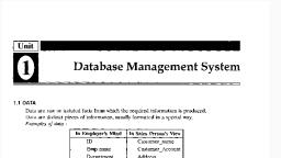
Unit 1 Database System Concept, , 1.1Concept of Data:, It is Individual Facts, Statistics or items of information, often numeric, that are, collected through Observation. Data are set of values of quantitative variables about one or, more persons or objects., , Database:, A database is a collection of information that is organized so that it can be easily, accessed, managed and updated. Computer databases typically contain aggregations of data, records or files, containing information about sales transactions or interactions with specific, customers., , DBMS:, A database management system is a software package designed to define, manipulate,, retrieve and manage data in a database. A DBMS manipulates the data itself, the data format,, field names, record and Files Structure. The DBMS manages incoming data, organizes it, and, provides ways for the data to be modified or extracted by users or other programs. Some DBMS, examples include MySQL, Microsoft Access, SQL Server, FileMaker, Oracle, RDBMS,, dBASE., , Advantages of DBMS over file processing System:, , 1. No redundant data: Redundancy removed by data normalization. No data duplication, saves storage and improves access time., 2. Data Consistency and Integrity: the root cause of data inconsistency is data, redundancy, since data normalization takes care of the data redundancy, data, inconsistency also been taken care of as part of it.
Page 2 :
3. Data Security: It is easier to apply access constraints in database systems so that only, authorized user is able to access the data. Each user has a different set of access thus, data is secured from the issues such as identity theft, data leaks and misuse of data., 4. Privacy: Limited access means privacy of data., 5. Easy access to data – Database systems manages data in such a way so that the data is, easily accessible with fast response times., 6. Easy recovery: Since database systems keeps the backup of data, it is easier to do a, full recovery of data in case of a failure., , 7. Flexible: Database systems are more flexible than file processing systems., Application of database:, •, , Railway Reservation System, Database is required to keep record of ticket booking, train’s departure and arrival, , status., •, , Library Management System, There are thousands of books in the library so it is very difficult to keep record of all, , the books in a copy or register. So DBMS used to maintain all the information relate to book, issue dates, name of the book, author and availability of the book., •, , Banking, We make thousands of transactions through banks daily and we can do this without, , going to the bank. So how banking has become so easy that by sitting at home we can send or, get money through banks., •, , Universities and colleges, Examinations are done online today and universities and colleges maintain all these, , records through DBMS. Student’s registrations details, results, courses and grades all the, information are stored in database., •, , Military, Military keeps records of millions of soldiers and it has millions of files that should be, , keep secured and safe. As DBMS provides a big security assurance to the military information, so it is widely used in militaries.
Page 3 :
•, , Online Shopping, Online shopping has become a big trend of these days. No one wants to go to shops, , and waste his time. Everyone wants to shop from home. So all these products are added and, sold only with the help of DBMS. Purchase information, invoice bills and payment, all of these, are done with the help of DBMS., , 1.2Three Level Architecture for database:, Three level Architecture for database:, 1. External level, 2. Conceptual level, 3. Internal level
Page 4 :
1. External level:, It is also called view level. The reason this level is called “view” is because several, users can view their desired data from this level which is internally fetched from database, with the help of conceptual and internal level mapping. The user doesn’t need to know the, database schema details such as data structure, table definition etc. user is only concerned, about data which is what returned back to the view level after it has been fetched from, database (present at the internal level). External level is the “top level” of the Three Level, DBMS Architecture., , 2.Conceptual level:, It is also called logical level. The whole design of the database such as relationship, among data, schema of data etc. are described in this level. Database constraints and, security are also implemented in this level of architecture. This level is maintained by DBA, (database administrator)., , 3. Internal level:, This level is also known as physical level. This level describes how the data is actually, stored in the storage devices. This level is also responsible for allocating space to the data., This is the lowest level of the architecture., , 1.3 Data Abstraction:, The major purpose of a database system is to provide users with an abstract view of the, system. The System hides certain details of how data is stored and created and maintained,, Complexity Should be hidden from database users., There are several levels of Abstraction:
Page 5 :
1. Internal Level/Schema:, The internal schema defines the physical storage structure of the database. The internal schema is, a very low-level representation of the entire database. It contains multiple occurrences of multiple, types of internal record. In the ANSI term, it is also called “stored record’., 2. Conceptual Schema/Level:, The conceptual schema describes the Database structure of the whole database for the community, of users. This schema hides information about the physical storage structures and focuses on, describing data types, entities, relationships, etc. This logical level comes between the user level, and physical storage view. However, there is only single conceptual view of a single database., 3.External Schema/Level :, external schema describes the part of the database which specific user is interested in. It, hides the unrelated details of the database from the user. There may be “n” number of external, views for each database. Each external view is defined using an external schema, which consists, of definitions of various types of external record of that specific view. An external view is just the, content of the database as it is seen by some specific particular user. For example, a user from the, sales department will see only sales related data.
Page 6 :
Instance:, The data stored in database at a particular moment of time is called instance of database., Database schema defines the variable declarations in tables that belong to a particular database, , Schema:, The overall design of the database is called as the database Schema. A database schema is, the skeleton structure that represents the logical view of the entire database. It defines how the, data is organized and how the relations among them are associated. It formulates all the, constraints that are to be applied on the data., , Data independence:, The ability to modify a schema definition in one level without affecting a schema definition in, higher level is called as data independence., There are two types of data independence:, 1. Logical Data Independence, o, , Logical data independence refers characteristic of being able to change the conceptual, schema without having to change the external schema., , o, , Logical data independence is used to separate the external level from the conceptual view., , o, , If we do any changes in the conceptual view of the data, then the user view of the data, would not be affected., , o, , Logical data independence occurs at the user interface level., , 2. Physical Data Independence, o, , Physical data independence can be defined as the capacity to change the internal schema, without having to change the conceptual schema., , o, , If we do any changes in the storage size of the database system server, then the Conceptual, structure of the database will not be affected., , o, , Physical data independence is used to separate conceptual levels from the internal levels.
Page 7 :
o, , Physical data independence occurs at the logical interface level., , Fig: Data Independence, , 1.4 Overall Structure of DBMS:, Database Management System (DBMS) is a software that allows access to data stored in a, database and provides an easy and effective method of, •, , Defining the information., , •, , Storing the information., , •, , Manipulating the information., , •, , Protecting the information from system crashes or data theft., , •, , Differentiating access permissions for different users., , The database system is divided into three components: Query Processor, Storage Manager, and, Disk Storage. These are explained as following below.
Page 8 :
1. Query Processor :, It interprets the requests (queries) received from end user via an application program into, instructions. It also executes the user request which is received from the DML compiler., Query Processor contains the following components –, , •, , DML Compiler –, It processes the DML statements into low level instruction (machine language), so that, they can be executed., , •, , DDL Interpreter –, It processes the DDL statements into a set of table containing meta data (data about
Page 9 :
data)., , •, , Embedded DML Pre-compiler –, It processes DML statements embedded in an application program into procedural calls., , •, , Query Optimizer –, It executes the instruction generated by DML Compiler., , 2. Storage Manager :, Storage Manager is a program that provides an interface between the data stored in the database, and the queries received. It is also known as Database Control System. It maintains the, consistency and integrity of the database by applying the constraints and executes, the DCL statements. It is responsible for updating, storing, deleting, and retrieving data in the, database., It contains the following components –, , •, , Authorization Manager –, It ensures role-based access control, i.e,. checks whether the particular person is, privileged to perform the requested operation or not., , •, , Integrity Manager –, It checks the integrity constraints when the database is modified., , •, , Transaction Manager –, It controls concurrent access by performing the operations in a scheduled way that it, receives the transaction. Thus, it ensures that the database remains in the consistent state, before and after the execution of a transaction.
Page 10 :
•, , File Manager –, It manages the file space and the data structure used to represent information in the, database., , •, , Buffer Manager –, It is responsible for cache memory and the transfer of data between the secondary storage, and main memory., , 3.Disk Storage :, It contains the following components, •, , Data Files –, It stores the data., , •, , Data Dictionary –, It contains the information about the structure of any database object. It is the repository, of information that governs the metadata., , •, , Indices –, It provides faster retrieval of data item., , 1.5 Data Modeling:, Data modeling is the process of creating a visual representation of either a whole, information system or parts of it to communicate connections between data points and structures., This provides a common, consistent, and predictable way of defining and managing data resources, across an organization, or even beyond., Record Based Logical model:, •, , Named so because the database is structured in fixed-format records of several types., , •, , Each record type defines a fixed number of fields, or attributes., , •, , Each field is usually of a fixed length.
Page 11 :
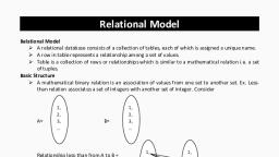
•, , Record based models do not include a mechanism for direct representation of code in the, database., , •, , The three most widely accepted models are the relational, network and hierarchical., , 1. Relational Model:, •, , Data and relationships are represented by a collection of tables., , •, , Each table has a number of columns with unique names, e.g. customer, account., , •, , Figure shows a sample relational database., , Stud_Id, , Stud_Name, , Address, , 100, , Joseph, , Clintor Town, , 101, , Rose, , Troy, , 102, , William, , Frasor Town, , Dept_Id, , Dept_Name, , 10, , Computer, , 20, , Electrical, , 30, , Computer, , Fig. Relational Model, , 2. Network Model:, •, , Data are represented by collections of records., , •, , Relationships among data are represented by links., , •, , Organization is that of an arbitrary graph., , •, , Fig. shows a sample network database that is the equivalent of the relational, database of Fig.
Page 12 :
Fig. Network Model, , 3. Hierarchical Model:, •, , Similar to the network model., , •, , Organization of the records is as a collection of trees, rather than arbitrary graphs., , •, , Fig. Shows a sample hierarchical database that is the equivalent of the relational, database of fig.
Page 13 :
Fig. Hierarchical Model, , 1.6 Data Modeling Using the E-R Model:, Data modeling is the process of creating a visual representation of either a whole information, system or parts of it to communicate connections between data points and structures., This provides a common, consistent, and predictable way of defining and managing data resources, across an organization, or even beyond., Entity Relationship Model:, o, , ER model stands for an Entity-Relationship model. It is a high-level data model. This, model is used to define the data elements and relationship for a specified system., , o, , It develops a conceptual design for the database. It also develops a very simple and easy to, design view of data., , o, , In ER modeling, the database structure is portrayed as a diagram called an entityrelationship diagram., , For example, Suppose we design a school database. In this database, the student will be an entity, with attributes like address, name, id, age, etc. The address can be another entity with attributes, like city, street name, pin code, etc and there will be a relationship between them.
Page 14 :
Strong Entity Set:, •, , A strong entity set is an entity set that contains sufficient attributes to uniquely identify all, its entities., , •, , In other words, a primary key exists for a strong entity set., , •, , Primary key of a strong entity set is represented by underlining it., , Weak Entity Set:, •, , A weak entity set is an entity set that does not contain sufficient attributes to uniquely, identify its entities., , •, , In other words, a primary key does not exist for a weak entity set.
Page 15 :
•, , However, it contains a partial key called as a discriminator., , •, , Discriminator can identify a group of entities from the entity set., , •, , Discriminator is represented by underlining with a dashed line., , Types of Attributes :, The attribute is used to describe the property of an entity. Eclipse is used to represent an attribute., For example, id, age, contact number, name, etc. can be attributes of a student., , a. Key Attribute, The key attribute is used to represent the main characteristics of an entity. It represents a primary, key. The key attribute is represented by an ellipse with the text underlined.
Page 16 :
b. Composite Attribute, An attribute that composed of many other attributes is known as a composite attribute. The, composite attribute is represented by an ellipse, and those ellipses are connected with an ellipse., , c. Multivalued Attribute, An attribute can have more than one value. These attributes are known as a multivalued attribute., The double oval is used to represent multivalued attribute., For example, a student can have more than one phone number.
Page 17 :
d. Derived Attribute, An attribute that can be derived from other attribute is known as a derived attribute. It can be, represented by a dashed ellipse., For example, A person's age changes over time and can be derived from another attribute like, Date of birth., , E-R Diagrams :, An ER diagram shows the relationship among entity sets. An entity set is a group of similar, entities and these entities can have attributes. In terms of DBMS, an entity is a table or attribute of
Page 18 :
a table in database, so by showing relationship among tables and their attributes, ER diagram, shows the complete logical structure of a database., , In the above diagram we have two entities Student and College and their relationship. The, relationship between Student and College is many to one as a college can have many students, however a student cannot study in multiple colleges at the same time. Student entity has attributes, such as Stu_Id, Stu_Name & Stu_Addr and College entity has attributes such as Col_ID &, Col_Name.
Page 19 :
Component Of ER Model:-, , 1., , 2., , 3., , Set of Entity, , Set Weak Entity, , Set of Attributes, , 4., , Multi Values Attributes, , 5., , Derived Attributes, , 6., , Set of Relationship
Page 20 :
7., , 8., , 9., , 10., , Set of Weak relation, , primary key Attribute, , Relationship and total participation, , Weak Entity’s Description Attribute
 Learn better on this topic