Notes of b e 1 sem, eme 21EME15 MODULE 4 - Study Material
Page 1 :
ELEMENTS OF MECHANICAL ENGG. (21EME15) MODULE-4 NOTES, MECHANICAL POWER TRANSMISSION – BELT,GEAR & CHAIN DRIVE, Mechanical Power Transmission:, The system that is used to transmit power from one mechanical element to another mechanical element is known as a, transmission system or drive. The mechanical power rotary motion speed and torque transmitted from one shaft to, other by means of 1.Gear drive,2.Belt drive,3. Chain Drive, 4. Clutches,5.Couplings,6.Rope Drive, Factors to be considered to select a transmission system, To select a suitable transmission system (e.g. either belt or chain drive) the following key factors are to be, considered., a), Distance between driver and driven pulley shaft, b), Operational speed and, c), Power to be transmitted, A gear is a toothed component within a transmission device that transmits rotational force to another gear or device, TYPES OF GEARS: 1. According to the position of axes of the shafts. a. Parallel, b. Intersecting & c. nonintersecting and non-parallel, a. Parallel, 1. Spur Gear: Teeth is parallel to axis of rotation.Transmit power from one shaft to another parallel shaft. They are, used widely in Electric screwdriver, oscillating sprinkler, windup alarm clock, washing machine and clothes dryer, 2. Helical Gear: The teeth on helical gears are cut at an angle to the face of the gear.This gradual engagement makes, helical gears operate much more smoothly and quietly than spur gears. Herringbone gears (Double Helical): To, avoid axial thrust, two helical gears of opposite hand can be mounted side by side, to cancel resulting thrust forces, Herringbone gears are mostly used on heavy machinery., 3. Rack and Pinion: Rack and pinion gears are used to convert rotation (From the pinion) into linear motion (of the, rack).A perfect example of this is the steering system on many cars., b. Intersecting, Bevel Gear: Bevel gears are useful when the direction of a shaft's rotation needs to be changed.They are usually, mounted on shafts that are 90 degrees apart, but can be designed to work at other angles as well. The teeth on bevel, gears can be straight, spiral or hypoid. They are used widely in locomotives, marine applications, automobiles,, printing presses, cooling towers, power plants, steel plants, railway track inspection machines, etc, c. Non-intersecting and Non-parallel, Worm and worm gears: Worm gears are used when large gear reductions are needed. It is common for worm gears, to have reductions of 20:1, and even up to 300:1 or greater. Many worm gears have an interesting property that no, other gear set has: the worm can easily turn the gear, but the gear cannot turn the worm.Worm gears are used widely, in material handling and transportation machinery, machine tools, automobiles etc., , Advantages of Gear drives over the belt/chain drives:, 1)It is a positive drive and the velocity ratio remains constant., 2) The center distance between the shafts is relatively small, which results in Compact construction., Dept. of Mechanical Engineering, BKIT, Bhalki,, , Dr.Rajashekar Matpathi, ME(Design), Ph.D, , 1
Page 2 :
ELEMENTS OF MECHANICAL ENGG. (21EME15) MODULE-4 NOTES, MECHANICAL POWER TRANSMISSION – BELT,GEAR & CHAIN DRIVE, 3) It can transmit very large power which is beyond the range of belt or chain drives., (4) It can transmit motion at very low velocity which is not possible with the belt drives., (5) The efficiency of gear drives is very high up to 99% in case of spur gear., (6) A provision can be made in the gearbox for the gear shifting, by just changing the velocity ratio over a wide range., Disadvantages of Gear Drives:, 1) The gear drives are costly, and the maintenance cost is also very high., (2) The manufacturing process for gears are complicated and highly specialized., (3) Gear drives require careful attention for lubrication and cleanliness., (4) Gear drives also requires precise alignment of the shaft., , • Pitch circle: A right section of the pitch surface., • Addendum circle: A circle bounding the ends of the teeth, in a right section of the gear., • Root (or dedendum) circle: The circle bounding the spaces between the teeth, in a right section of the gear., • Addendum: The radial distance between the pitch circle and the addendum circle., • Dedendum: The radial distance between the pitch circle and the root circle., • Clearance: The difference between the dedendum of one gear and the addendum of the mating gear., • Circular pitch (Pc) : The width of a tooth and a space, measured on the pitch circle., • Diametral pitch (Pd): The number of teeth of a gear unit pitch diameter. The diametral pitch is, by definition,, the number of teeth divided by the pitch diameter., • Module (m): Pitch diameter divided by number of teeth. The pitch diameter is usually specified in inches or, millimeters; in the former case the module is the inverse of diametral pitch., T = number of teeth, T, P, =, D = pitch diameter, Diametral pitch d, D, D = pitch diameter, D, P, Circular pitch, T = number of teeth, c, , T, , 2 N 2 d1, =, =, 1 N1 d 2, , Velocity Ratio =, , Module, , m = D/T, , ω= Angular speed, N =Speed of the wheel, d= Diameter of the wheel, D = pitch diameter, T= Number of teeth, , Dept. of Mechanical Engineering, BKIT, Bhalki,, , Dr.Rajashekar Matpathi, ME(Design), Ph.D, , 2
Page 3 :
ELEMENTS OF MECHANICAL ENGG. (21EME15) MODULE-4 NOTES, MECHANICAL POWER TRANSMISSION – BELT,GEAR & CHAIN DRIVE, 1. Determine the module of a pair of gears whose center distance is 58mm. The gears have 18 and 40 teeth, respectively. Also determine the pitch circle radii and circular pitch of the gears, , 2. A 3mm module 20 pinion, of 18 teeth drives a 45-tooth gear. Calculate the pitch radii, base radii,, tooth thickness on the pitch circle., , Q. Define ‘Gear Train’. State its purpose and types of gear train., Definition: When two or more gears are made to mesh with each other to transmit power from one shaft to, another. Such a combination is called gear train, Purpose: The purpose of the train used is, 1.To obtain correct & required velocity ratio between driver & driven shafts., 2.To decide upon the relative position of the axes of shafts., 3.To decide upon amount of power to be transmitted between shafts, Types: Following are the different types of gear trains, depending upon the arrangement of wheels :, 1. Simple gear train,, 2. Compound gear train,, 3. Reverted gear train, and, 4. Epicyclic gear train., Dept. of Mechanical Engineering, BKIT, Bhalki,, , Dr.Rajashekar Matpathi, ME(Design), Ph.D, , 3
Page 4 :
ELEMENTS OF MECHANICAL ENGG. (21EME15) MODULE-4 NOTES, MECHANICAL POWER TRANSMISSION – BELT,GEAR & CHAIN DRIVE, Simple Gear Train :The most common of the gear train is the gear pair connecting parallel shafts. The, teeth of this type can be spur, helical or herringbone. only one gear for each axis. The angular velocity is simply, the reverse of the tooth ratio. The main limitation of a simple gear train is that the maximum speed change ratio, is 10:1. For larger ratio, large sizes of gear trains are required. The sprockets and chain in the bicycle is an, example of simple gear train. When the paddle is pushed, the front gear is turned and that meshes with the links, in the chain. The chain moves and meshes with the links in the rear gear that is attached to the rear wheel. This, enables the bicycle to move., , Compound Gear Train:, For large velocities, compound arrangement is preferred. Two keys are keyed to a single shaft. A double, reduction train can be arranged to have its input and output shafts in a line, by choosing equal center distance, for gears and pinions. Two or more gears may rotate about a single axis., , Planetary Gear Train (Epicyclic Gear Train):, Epicyclic gearing also called as planetary gearing. It is a gear system that consists of one or more outer gear, (planet gear) rotating about a central (sun gear). The planet gear are mounted on a moveable arm (carrier) which, itself may rotate relative to the sun gear., , Fig.a) Planetary Gear Train, , Fig.b) Simple Epicyclic Gear Train, , Dept. of Mechanical Engineering, BKIT, Bhalki,, , Dr.Rajashekar Matpathi, ME(Design), Ph.D, , 4
Page 5 :
ELEMENTS OF MECHANICAL ENGG. (21EME15) MODULE-4 NOTES, MECHANICAL POWER TRANSMISSION – BELT,GEAR & CHAIN DRIVE, More speed or torque ratios can be achieved by increasing the number of planet and sun gear in epicyclic gear, box. In the epicyclic gearbox, the epicyclic gear train is a very general term. Basically, it involves 3 gears: a sun, gear, a planet gear and a ring gear, the underlying concept being many gear ratios can be obtained from a small, volume as compared to other types of gear trains which take up more space., , Advantages of Epicyclic Gearbox :, 1., 2., 3., 4., 5., 6., 7., , The planetary gearbox offers a set of distinct advantages which makes it an interesting alternative to, traditional gear types such as helical and parallel shaft gearboxes in applications requiring:, High reduction ratios, Compact and lightweight with high torque transmission, High radial loads on the output shaft, It is quieter in operation, Uniform distribution of load over all gears having greater tooth contact., All gears are constantly in mesh, so a change of one gear to another is possible without any loss., , Disadvantages of planetary gear systems, 1. Complexity, 2. Assembly of gears is limited to specific teeth per gear ratios, 3. Efficiency calculations are difficult, 4. Driver and driven equipment must be in line to avoid additional gearing, , Application of Epicyclic Gear train :, 1. A good example of the everyday application of a planetary gear system is the automatic transmission of a, car., 2. The epicyclic gear trains are used in the back gear of lathe, differential gears of the automobiles, hoists,, pulley blocks, wrist watches, etc., 3. The epicyclic gear trains are useful for transmitting high-velocity ratios with gears of moderate size in a, comparatively lesser space., , What is belt drive? How many types of belts are used for power transmission?, BELT DRIVE : It is one of the most effective method of transmitting power from one mechanical element, to another mechanical element, by means of a thin inextensible belt running over two pulleys as transmission, system. Belt drives are employed for power transmission when the distance between the shafts is large, and when, exact speed of the driven shaft is not a main criteria Motion is transmitted due to frictional force between, the pulleys and the belt surface., BELT MATERIAL The materials used for belts must be strong, flexible and durable. It should have a high, coefficient of friction. The different materials used in manufacturing of belt are Leather, Rubber, Cotton or, Fabric and Balata., Types of Belt:, , TIMING BELT is a toothed endless belt which is a part of an internal combustion engine that synchronizes, the rotation of the crankshaft and the camshaft(s) so that the engine's valves open and close at the proper times during, each cylinder's intake and exhaust strokes., ., Dept. of Mechanical Engineering, BKIT, Bhalki,, , Dr.Rajashekar Matpathi, ME(Design), Ph.D, , 5
Page 6 :
ELEMENTS OF MECHANICAL ENGG. (21EME15) MODULE-4 NOTES, MECHANICAL POWER TRANSMISSION – BELT,GEAR & CHAIN DRIVE, Open belt drive: The driving and the driven, pulley are rotating in the same direction., The angle of lap on the smaller pulley is less, than the angle of lap on the larger pulley, No rubbing in belt, hence, wear and tear, less, , Cross belt drive: The driving and the driven pulley rotate, in opposite directions, The angle of lap is same on both the pulleys, , Length of Open belt drive, , Length of Cross belt drive, , At belt crosses, it rubs against each other and there will, be excessive wear and tear. Hence shaft should be placed, at a maximum distance of 20b, where b is the width of, belt and the speed of the belt should be less than 15m/s., , Velocity Ratio of Belt Drive, V.R= N2/N1 = d1/d2 =, , =, , It is the ratio between the velocities of the follower or driven to the driver., d 1 = Diameter of the driver pulley d 2 = Diameter of the follower, N 1 = Speed of the driver in r.p.m., and N 2 = Speed of the follower in r.p.m, Since the length of belt that passes over the driver in one minute is equal to the length of belt that passes over the, follower in one minute, therefore π d 1 N 1 = π d 2 . N 2, , Slip of Belt: Slip is the difference between the linear velocities of pulley (driver/driven) & belt.A forward motion of, the belt without carrying the driven pulley with it, is called as slip of the belt and is generally expressed as a, percentage. Reasons for slip are1.Smaller angle of contact 2.Low Coefficient of friction between belt & pulley, surface. Slip and creep are undesired factors as they reduce velocity ratio, in turn power transmission., , Effect of slip on velocity ratio: Result of belt slipping is to reduce the velocity ratio of the system, Creep of Belt: When the belt passes from the slack side to the tight side, a certain portion of the belt extends, and it, contracts again when the belt passes from the tight side to slack side. Due to these changes of length, there is a, relative motion between the belt and the pulley surfaces. This relative motion is termed as creep. The total effect of, creep is to reduce slightly the speed of the driven pulley or follower. The velocity ratio is given by, 1 and 2 = Stress in the belt on the tight and slack side respectively,, and E = Young’s modulus for the material of the belt., Effect of creep on velocity ratio: The total effect of creep is to reduce slightly the speed of the driven pulley, Dept. of Mechanical Engineering, BKIT, Bhalki,, , Dr.Rajashekar Matpathi, ME(Design), Ph.D, , 6
Page 7 :
ELEMENTS OF MECHANICAL ENGG. (21EME15) MODULE-4 NOTES, MECHANICAL POWER TRANSMISSION – BELT,GEAR & CHAIN DRIVE, or follower., , ADVANTAGES AND DISADVANTAGES OF FLAT BELT DRIVE, Advantages, Disadvantages, (i) Running and maintenance cost is low., (i) Not a positive drive (due to slip), (ii) Possibility to transmit power over a moderately, (ii) Not preferred for short center distance, long distance., (iii) Belt joints reduces the life of the belt., (iii) Efficient at high speeds, (iv) Loss of power due to slip and creep., ADVANTAGES AND DISADVANTAGES OF V-BELT DRIVE (0.5kW - 150 kW) is possible by this drive., Advantages of V-belts, Disadvantages of V-belts, (i) The drive is positive, because the slip between the 1. The V-belt drive cannot be used for large centre, belt and the pulley groove is negligible., distances., (ii) More suitable for transmission of power for short 2. Initial cost is more as it requires V-grooves on the, center distance., pulley., (iii) There is no joints problem as the drive is of, 3. Durability of V-belts is less compared to flat belts, endless, (iv) Compact and gives high velocity ratio., (v) Can be easily installed and removed., , Chain drive: It is a way of mechanical power transmission. It consists of endless series of chain link known, as roller chain which meshed with toothed sprocket gear. This type of power transmission mainly used in, motorcycle., , The rigid links of chain hinged together by pin joint, that provide the chain necessary flexibility to wrap, around the sprocket. The sprocket has projecting teeth of special profile and it perfectly fit in to the recess of, chain link. Thus the sprocket and chain constrained to move together. The first sprocket in on the driving, shaft, it will pull the chain. The chain then drag the second sprocket is on the drive shaft. By varying the, diameter of input and output gears, the gear ratio can be altered. For example one rotation in bicycle pedal, cause more than on one rotation of gear mounted on wheel. Without slipping, chain drive ensures the perfect, velocity ratio., Advantages of chain drive over belt drive., Dept. of Mechanical Engineering, BKIT, Bhalki,, , Dr.Rajashekar Matpathi, ME(Design), Ph.D, , 7
Page 8 :
ELEMENTS OF MECHANICAL ENGG. (21EME15) MODULE-4 NOTES, MECHANICAL POWER TRANSMISSION – BELT,GEAR & CHAIN DRIVE, 1. No slip takes place in chain drive as in belt drive there is slip., 2. Occupy less space as compared to belt drive., 3. High transmission efficiency., 4. More power transmission than belts drive., 5. Operated at adverse temperature and atmospheric conditions., 6. Higher velocity ratio. g) Used for both long as well as short distances, Disadvantages of chain drive, 1. There may be velocity fluctuation and under excessively stretched chain conditions., 2. Conventional chain drive suffers vibrations due to chordal effect., 3. The production of chain drive is higher than belt drives., 4. The chain drive needs accurate and careful mounting., 5. The chain drive need careful maintenance, lubrication and slack adjustments., 6. If there is no frequent proper lubrication the chain wear out faster than belts and ropes, , 1.Two pulleys, one 450 mm diameter and the other 200 mm diameter are on parallel shafts 1.95 m apart, and are connected by a crossed belt. Find the length of the belt required and the angle of contact between, the belt and each pulley.What power can be transmitted by the belt when the larger pulley rotates at 200, rev/min, if the maximum permissible tension in the belt is 1 kN, and the coefficient of friction between the, belt and pulley is 0.25 ?, Given : d1= 450 mm = 0.45 m or r1= 0.225 m ;d2= 200 mm = 0.2 m or r2= 0.1 m ; x= 1.95 m ; N1= 200 r.p.m. ;, T1= 1 kN = 1000 N ; µ = 0.25 We know that speed of the belt,, , Dept. of Mechanical Engineering, BKIT, Bhalki,, , Dr.Rajashekar Matpathi, ME(Design), Ph.D, , 8
Page 9 :
ELEMENTS OF MECHANICAL ENGG. (21EME15) MODULE-4 NOTES, MECHANICAL POWER TRANSMISSION – BELT,GEAR & CHAIN DRIVE, , 3.A shaft runs at 80 rpm & drives another shaft at 150 rpm through belt drive. The diameter of, the driving pulley is 600 mm. Determine the diameter of the driven pulley in the following cases:, (i) Taking belt thickness as 5 mm. (ii) Assuming for belt thickness 5 mm and total slip of 4%., Ans.: Given data; N1 = 80 rpm. N2 =150 rpm. D1= 600 mm. S = 4 % To find; D2 =?;, (i) Case I: Taking t = 5 mm. Velocity ratio, (V.R.) N2/N1 = (D1 + t)/ (D2 + t), 150/80 = (600 + 5)/ (D2 + 5), :. diameter of driven pulley D2 = 317.66 mm ~ 318mm, (ii) Case II: Assuming for belt thickness 5 mm and total slip of 4%., Velocity ratio, (V.R.) N2/N1 = {(D1 + t)/ (D2 + t)} × {1- (S/100)}, 150/80 = {(600 + 5) / (D2 + 5)} × {1- (4/100):. dia of driven pulley D2 = 304.76 mm ~ 305 mm, 4. A shaft runs at 800 rpm and drives another shaft at 150 rpm through belt drive. The diameter of, the driving pulley is 600 mm. Determine the diameter of the driven pulley in the following cases:, i. Neglecting belt thickness,, ii. Taking belt thickness as 5 mm,, iii. Assuming for case a total slip of 4%, and, iv. Assuming for case a slip of 2% on each pulley, Dept. of Mechanical Engineering, BKIT, Bhalki,, , Dr.Rajashekar Matpathi, ME(Design), Ph.D, , 9
Page 10 :
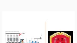
ELEMENTS OF MECHANICAL ENGG. (21EME15) MODULE-4 NOTES, MECHANICAL POWER TRANSMISSION – BELT,GEAR & CHAIN DRIVE, , Mechanism: A mechanism considered to be an assembly of rigid bodies connected together by joints, designed to achieve a specific purpose within a machine. The word mechanism has many meanings., In kinematics, a mechanism is a means of transmitting, controlling, or constraining relative movement., Movements which are electrically, magnetically, pneumatically operated are excluded from the, concept of mechanism., Types of Mechanism: 1 Four bar chain. 2. Single slider crank, 3.Double slider crank, , Machine: an assemblage of parts that transmit forces, motion, and energy in a, predetermined manner for useful work., Simple Machine: any of various elementary mechanisms having the elements of which all, machines are composed. Included in this category are the lever, wheel and axle, pulley,, inclined plane, wedge, and the screw., Similarity between machines and mechanisms is that they are both combinations of, rigid bodies and the relative motion among the rigid bodies is definite., Difference between machine and mechanism is that machines transform energy to do, work, while mechanisms so not necessarily perform this function. Figure a) shows a picture, of the main part of a diesel engine. The mechanism of its cylinder-link-crank parts is, a slider-crank mechanism, as shown in Figure b)., , Figure a), , Figure b), , Inversion of Mechanism: The method of obtaining different mechanisms by fixing different, links in a kinematic chain, is known as inversion of the mechanism., Absolute motion is measured with respect to a stationary frame. Relative motion is measured for, one point or link with respect to another link. We have already stated that when one of links is, Dept. of Mechanical Engineering, BKIT, Bhalki,, , Dr.Rajashekar Matpathi, ME(Design), Ph.D, , 10
Page 11 :
ELEMENTS OF MECHANICAL ENGG. (21EME15) MODULE-4 NOTES, MECHANICAL POWER TRANSMISSION – BELT,GEAR & CHAIN DRIVE, fixed in a kinematic chain, it is called a mechanism. So we can obtain as many mechanisms as, the number of links in a kinematic chain by fixing, in turn, different links in a kinematic chain, , 1.Inversions of Four bar mechanism :, , 2.Single slider chain mechanism four inversions :, , 3. Double slider chain mechanism four inversions:, , Linear Actuators, Stationary Screws with rotating nuts, This group include machine tool traversing mechanisms, jacks, valve drives etc etc., These mechanisms essentially convert rotary motion to linear motion. High mechanical advantages can, result from components which are convenient to design and engineer. The output motions and forces, are very easy to evaluate for the input forces., Dept. of Mechanical Engineering, BKIT, Bhalki,, Dr.Rajashekar Matpathi, ME(Design), Ph.D 11
Page 12 :
ELEMENTS OF MECHANICAL ENGG. (21EME15) MODULE-4 NOTES, MECHANICAL POWER TRANSMISSION – BELT,GEAR & CHAIN DRIVE, Stationary Nuts with with rotating screw, This group includes power screw actuators, valve drives, jacks. The characteristics of this group is, essentially the same as the group with stationary screws and rotating nuts, Single and double acting hydraulic and pneumatic cylinders, This is a massive group including positioning cylinders, rams jacks . The motions and forces are very, easy to calculate..The motion involves convertion of potential energy in fluid to kinetic energy of the, motion of the component moved by the cylinder, , Fine adjustment mechanisms, A fine adjusting mechanism is primarily used for control where small movements are required resulting, from larger movements of the input. The variations of this group include screws, differential screws,, gears, cams.etc etc. A typical method of providing small output rotations from input motions is shown, below.. One rotation of the input shaft will result in a linear motion of the carriage of 0,5mm.., , Clamping Mechanisms::Typical clamping mechanisms include toolmakers clamps, G clamps,, screw clamps, clamps based on cams. Clamps result from lever actions, screw forces, toggle, motions..The two important factors in the engineering of a clamp is the method of applying a high force, and the method of retaining the force after removal of the input motion..., , Toggle Clamp, Toolmakers Clamp, , G Clamp, , Horizontal In-Line Toggle Clamp, , Cam, Clamp, , Vertical Toggle Clamp, , Location Devices: Location devices often involve positioning and centralizing of the component, being located. Jigs and fixtures are used widely in industry for locating items prior to machining or, assembly., Ratchets: A ratchet is used to ensure that the motion of the output device is only allow in one, direction even though the input motion may be in either direction or oscillatory. Refer to Links below, Dept. of Mechanical Engineering, BKIT, Bhalki,, , Dr.Rajashekar Matpathi, ME(Design), Ph.D, , 12
Page 13 :
ELEMENTS OF MECHANICAL ENGG. (21EME15) MODULE-4 NOTES, MECHANICAL POWER TRANSMISSION – BELT,GEAR & CHAIN DRIVE, , Escapements: Escapements are used for to control continuous motion to produce a highly, controlled step motion at a fixed rate. Escapements are used for mechanically driven clocks. When used, with clocks the escapement controls the spring driven clock mechanism such that it moves in regulated, steps controlled by a pendulum or an oscillating arm . Refer to Links below, Indexing Mechanisms: Indexing mechanisms generally converts a rotating, rocking or oscillatory, motion to a series of step movements of the output link or shaft. Indexing mechanisms are useful for, counters and machine tool feeds., Swinging Or Rocking Mechanisms, This type of mechanism produces a swinging or rocking motion of a link. The motion is generally less, than 360o and is an oscillatory motion., , Rocking/ Oscillatory Mechanism: Reciprocating Mechanisms Reciprocating straight line motion, is most generally completed using pneumatic, hydraulic, and electric linear actuators. Reciprocating, motion is also achieved using rack and pinion, and cams. Historically a number of machines have been, operated very successfully using specially developed mechanisms., Reversing Mechanisms: It is comparatively easy to obtain reversing motion using pneumatic,, hydraulic, levers and gears methods., , Reverse Linear Motion Using, 2-Racks and a Pinion, , Reverse Rotational Motion, using 2 Pinions, , Reverse Linear Motion, using Links, , A mechanism capable of delivering output motion in either direction can also be achieved using, pneumatic and hydraulic systems with appropriate direction control valves. A lever or gear type system, would require the use of some type of clutch. Some two-way clutches which connect one output shaft to, one of two drive shafts rotating in the opposite directions can result in a direction reversal of the output, shaft without stopping the drive shaft. This, of course assumes no problems due to inertia., , Rotational Couplings / Connectors, Transmitting motion between parallel, coaxial, intersecting and skewed shafts is achieved using mechanical, coupling systems. There are a wide range of different designs of couplings. The basic simple design of, coupling is used to transmit rotary motion in both directions between two co-axial shaft. The design of, these couplings is based on the torque to be transmitted, the speed, and the degree of misalignment. The, available range of gear designs can be used to connect shafts of virtually any relative orientation. Gears not, only, allow, the, transfer, of, rotation, but, also, direction, and, speed., Belt drives can also be used to couple shafts together. The method can accommodate various relative shaft, positions and can be designed such that the relative shaft positions can vary as rotation is taking place., Chain drives provide more positive coupling than belt drives but are not as positive as gear drives.., Typical couplings based on simple link systems are shown below. These methods are limited in the power, that can be transmitted and the evenness of the output shaft motion, , Definition of a Robot : A robot is a programmable, multifunctional manipulators, designed to move, toward materials parts, tools or special devices through variable programmed motions for the, performance of a variety of tasks., Need of Robots: General characteristics of industrial work situations that promote the use of, industrial robots, Dept. of Mechanical Engineering, BKIT, Bhalki,, , Dr.Rajashekar Matpathi, ME(Design), Ph.D, , 13
Page 14 :
ELEMENTS OF MECHANICAL ENGG. (21EME15) MODULE-4 NOTES, MECHANICAL POWER TRANSMISSION – BELT,GEAR & CHAIN DRIVE, 1. Hazardous work environment for humans, 2. Repetitive work cycle, 3. Difficult handling task for humans, 4. Multi shift operations, 5. Infrequent changeovers, 6. Part position and orientation are established in the work cell, , Anatomy Robot: The anatomy of robot is also known as structure of robot. The basic components, or sections in anatomy of robots are as follows. The anatomy of industrial robots deals with the, assembling of outer components of a robot such as wrist, arm, body, joints, and Links. In addition,, they have other supporting components like a microcomputer external sensor. A jointed arm robot, with various components is shown in fig., , Arm and body motions:, 1. Vertical traverse: Up and down motion of the arm, caused by pivoting the entire arm about a, horizontal axis or moving the arm along a vertical slide., 2. Radial traverse: extension and retraction of the arm (in and out movement), 3. Rotational traverse: rotation about the vertical axis (right or left swivel of the robot arm), , Wrist Motion:, 1. Wrist swivel: Rotation of the wrist,, 2. Wrist bend: Up or down movement of the wrist, external sensors this also involves rotation, movement, 3. Wrist yaw: Right or left swivel of the wrist., , Type of joints. :An industrial robot is a general purpose, programmable machine having certain, anthropomorphizes (i.e., human – like) characteristics, like the arm with following different type of joints., , Robot Physical Configuration Control System : Industrial robots come in a variety of, shapes and sizes. They are capable of various arm manipulations, and they possess different motion, systems. There are four basic configurations, Dept. of Mechanical Engineering, BKIT, Bhalki,, Dr.Rajashekar Matpathi, ME(Design), Ph.D 14
Page 15 :
ELEMENTS OF MECHANICAL ENGG. (21EME15) MODULE-4 NOTES, MECHANICAL POWER TRANSMISSION – BELT,GEAR & CHAIN DRIVE, 1.Cartesian configuration: A robot which is constructed around this configuration consists of three, orthogonal slides, as shown in fig. the three slides are parallel to the x, y, and z axes of the Cartesian, coordinate system. By appropriate movements of these slides, the robot is capable of moving its arm at any, point within its three-dimensional rectangular spaced work space., Advantages: • Highly accurate & speed, • Fewer cost, • Simple operating procedures,& • High, payloads. Disadvantages: • Less work envelope, Reduced flexibility, 2. Cylindrical configuration: in this configuration, the robot body is a vertical column that swivels about a, vertical axis. The arm consists of several orthogonal slides which allow the arm to be moved up or down and, in and out with respect to the body., Advantages: • Increased flexibility, • Huge work volume, and • Quick operation., Disadvantages: • Very expensive, • Difficult operating procedures, and • Plenty of components., 3. Polar configuration: this configuration also goes by the name “spherical coordinate” because the, workspace within which it can move its arm is a partial sphere as shown in figure. The robot has a rotary, base and a pivot that can be used to raise and lower a telescoping arm., 4. Jointed-arm configuration: is combination of cylindrical and articulated configurations. This is similar, in appearance to the human arm, as shown in fig. the arm consists of several straight members connected by, joints which are analogous to the human shoulder, elbow, and wrist. The robot arm is mounted to a base, which can be rotated to provide the robot with the capacity to work within a quasi-spherical space., , End Effectors:, End effector is a device which is attached to the robot’s wrist to perform a specific task. The task, might be work part handling, spot welding, spray painting, or any of a great variety of other, functions. The possibilities are limited only by the imagination and ingenuity of the application, engineers who design robot systems. The end effectors are the special purpose tooling which enables, the robot to perform a particular job. It is usually custom engineered for that job, either by the, company that owns the robot or company that sold the robots. Most robot manufacturer has, engineered groups which design and fabricate end effectors or provide advice to their customers on, end effectors design., For purpose organization, we will divide the various types of end effectors into two categories:, Grippers and Tools., 1. Grippers: are generally used to grasp and hold an object and place it at a desired location., Grippers can be classified as 1.Mechanical grippers, 2.Vacuum or suction cups 3. Magnetic gripper,, 4.Adhesive grippers, 5.Hooks, 6.Scoops,, , Dept. of Mechanical Engineering, BKIT, Bhalki,, , Dr.Rajashekar Matpathi, ME(Design), Ph.D, , 15
Page 16 :
ELEMENTS OF MECHANICAL ENGG. (21EME15) MODULE-4 NOTES, MECHANICAL POWER TRANSMISSION – BELT,GEAR & CHAIN DRIVE, 2. Tools: a robot is required to manipulate a tool to perform an operation on a work part. Here the tool, acts as end-effectors., 1. Spot-welding tools 2. Arc-welding tools,, 3. Spray painting nozzles, 4. Rotating spindles for drilling and grinding, , ROBOT APPLICATIONS:, Industrial Robot Applications can be divided into following categories, 1. Material-handling applications:, • Involve the movement of material or parts from one location to another., • It includes part placement, palletizing and/or depalletizing, machine loading and unloading., 2. Processing Operations:, • Requires the robot to manipulate a special process tool as the end effectors., • The application include spot welding, arc welding, riveting, spray painting, machining, metal cutting,, deburring, polishing., 3. Assembly Applications:, • Involve part-handling manipulations of a special tools and other automatic tasks and operations., 4. Inspection Operations:, • Require the robot to position a work part to an inspection device., • Involve the robot to manipulate a device or sensor to perform the inspection., , Advantages of Robots:, 1., 2., 3., 4., 5., 6., 7., 8., , Robotics and automation can, in many situation, increase productivity, safety, efficiency, quality, and, consistency of Products, Robots can work in hazardous environments, Robots need no environmental comfort, Robots work continuously without any humanity needs and illnesses, Robots have repeatable precision at all times, Robots can be much more accurate than humans; they may have milli or micro inch accuracy., Robots and their sensors can have capabilities beyond that of humans., Robots can process multiple stimuli or tasks simultaneously, humans can only one., Robots replace human workers who can create economic problems., , Disadvantages of Robots:, • Robots lack capability to respond in emergencies, this can cause: 1.Inappropriate and wrong, responses, 2.A lack of decision-making power, 3.A loss of power, 4.Damage to the robot and other, devices 5.Human injuries, • Robots may have limited capabilities in 1.Degrees of Freedom 2.Dexterity 3.Sensors 4.Vision, systems 5.Real-time Response, • Robots are costly, due to 1.Initial cost of equipment 2.Installation Costs 3.Need for peripherals, 4.Need for training 5.Need for Programming, , Dept. of Mechanical Engineering, BKIT, Bhalki,, , Dr.Rajashekar Matpathi, ME(Design), Ph.D, , 16
 Learn better on this topic