Page 1 :
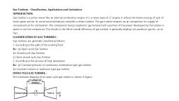
ELEMENTS OF MECHANICAL ENGINEERING (21EME15), , MODULE-1 HYDRAULIC (WATER) TURBINES:, Hydraulic or water turbines are the machines which convert the kinetic and potential energies possessed by, water into mechanical rotary motion or power. These are further coupled to electric generators to produce, electric power. The water is stored in artificially created reservoirs by constructing dams across flowing rivers., CLASSIFICATION OF WATER TURBINES:, i) Type of action of the water on the Turbine a) Impulse turbine: b) Reaction Turbines:, Impulse turbine: The total potential energy of water is converted to kinetic energy in the nozzles. The, impulse due to the high velocity jet coming out of the nozzles is used to turn the turbine wheel. The pressure, inside the turbine is atmospheric. It is found suitable in when the available potential energy is high and flow, available is comparatively low. E.g. Pelton wheel, Reaction Turbines: Water enters the runner under pressure having some velocity head. While the water, passes over the runner, its pressure is gradually converted into velocity head until its pressure is reduced to, atmospheric pressure alongwith the change in K.E based on its absolute velocity., ii) Based on Direction of Flow of Water through the Runner:, Radial flow: Inward radial flow: Old Francis turbine: Outward radial flow: Fourneyron Turbine, Axial Flow Turbines: Kaplan and propeller turbines, Mixed Flow Turbines: Modern Francis turbine, iii)Based on Available Head and Discharge, Reaction turbines are used for low and medium heads., Medium Head Turbines: 60m-250m- Medium flow rate: Modern Francis, Low Head Turbines: Head<60m- Large flow rates: Axial flow Kaplan and propeller turbines., iv) Based on Specific Speed( Ns): Pelton turbine, Ns=9 to 35, Francis turbine, Ns=50 to 250, , Kaplan turbine, Ns=250 to 850, , v) Based on position of Shaft: Horizontal shaft type, Vertical shaft type, , Specific Speed of Pump : The specific speed ns of a centrifugal pump is the required speed of one of, the present pumps which are geometrically similar in all parts, which delivers a flow rate of 1 m3/s at a, head of 1 m. The term is used for comparing numerically different centrifugal pumps. This is a variable, obtained from the service data which has great practical significance for the design and choice of pumps., , IMPULSE TURBINE OR PELTON WHEEL: The pelton wheel is the most commonly used type, , Department of Mechanical Engineering, BKIT, Bhalki, , Dr.Rajashekar Matpathi
Page 2 :
ELEMENTS OF MECHANICAL ENGINEERING (21EME15), of impulse turbine. It works under a high head and requires small quantity of water. Fig. shows a schematic, sketch of a Pelton Wheel. The water from a high head source is supplied to the nozzle provided with a needle,, which controls the quantity of water flowing out of the nozzle. The pressure energy of water is converted, into velocity energy as it flows through the nozzle. The jet of water issuing out of the nozzle at high velocity, impinges on the curved blades known as pelton cups, at the centre as shown in the adjoining figure. The, impulsive force of the jet striking on the Pelton cups sets up the pelton wheel to rotate in the direction of the, impinging jet. Thus the pressure energy of the water is converted into mechanical energy. The pressure inside, the casing of the turbine will be at atmospheric pressure., , Q. Differentiate between impulse and reaction water turbines:, Impulse turbine, There is no pressure change of the fluid in, the turbine rotor blades., The entire water energy is converted in to kinetic energy., Work done is by the change in kinetic energy of the jet., 4.The water flows through the nozzle and impinges on the, buckets., 5.Draft tube is not necessary, 6.Newton’s second lay describes the transfer of energy., Example: Pelton wheel, , Department of Mechanical Engineering, BKIT, Bhalki, , Reaction turbine, The pressure of the water changes as it passes through, the turbine rotor blades., No energy conversion., Work done Is partly by the change in the velocity head, and almost entirely by the change in pressure head., The water is guided by the guide blades to flow over the, moving vanes., Draft tube is necessary, Newton’s second law describes the transfer of energy., Example: Francis turbine, Kaplan turbine, , Dr.Rajashekar Matpathi
Page 3 :
ELEMENTS OF MECHANICAL ENGINEERING (21EME15), Francis Turbine:, The Francis turbine is a medium head reaction turbine in which water flows radially inwards. Fig shows a simple, schematic representation of the Francis turbine. It consists of a spiral casing enclosing a number of stationary, guide blades fixed all-round the circumference of an inner ring of moving vanes forming the runner which is, keyed to the turbine shaft. Water at high pressure enters through the inlet in the casing and flows radially inwards, to the outer periphery of the runner through the guide blades. From the outer periphery of the runner the water, flows inwards through the moving vanes and discharges at the centre of the runner at lower pressure. During its, flow over the moving blades it imparts kinetic energy to the runner to set it into rotational motion. To enable, the discharge of water at lower pressure, a diverging conical tube called draft tube is fitted at the centre of the, runner. The other end of the draft tube is immersed in the discharging side of the water known as tail race., , KAPLAN TURBINES:, The Kaplan turbine is a low head reaction turbine in which water flows axially. Fig shows a simple, schematic representation of a Kaplan turbine. All the parts of the turbine are similar to that of the Francis, turbine except the runner and the draft tube. The runner of the Kaplan turbine resembles with the propeller, of the ship, hence sometimes the Kaplan turbine is also called Propeller turbine., The water at high pressure enters the turbine casing through the inlet and flows over the guide blades. The, water from the guide blades strikes the runner blades axially imparting the kinetic energy to set it into, rotational motion. The water discharging at the centre of the runner in the axial direction into the draft, tube which is in L-shape having its discharging end immersed into the tailrace., , Department of Mechanical Engineering, BKIT, Bhalki, , Dr.Rajashekar Matpathi
Page 4 :
ELEMENTS OF MECHANICAL ENGINEERING (21EME15), , Q. Difference between Kaplan Turbine and Francis Turbine:, Kaplan Turbine, Kaplan turbine is a compact unit., , Francis Turbine, Francis turbine is not a compact unit., , For a given head and output Kaplan turbine runs at a, , For a given head and output, the Francis turbine runs at a, , higher speed., , lower speed., , This is an axial flow turbine., , This is radial flow type and also a mixed flow type., , This turbine has a small number of blades (generally 4). This has many blades (about 10 to 20)., This turbine is suitable for low heads., , This turbine is suitable for medium heads., , This turbine utilizes large discharges at low heads., , This turbine utilizes medium discharge at medium head., , This turbine has a specific speed in the range 260 to 860, , This turbine has a specific speed in the range 50 to 260, , Efficiency of Kaplan turbineis more when compared to, , Efficiency of Francis turbine is less when compared to, , Francis turbine, , Kaplan turbine, , Hydraulic Pump: Pump can be broadly defined as ‘a mechanical device to increase the pressure energy of a, water’. Pumps are mostly used for lifting fluids (liquids or gases) from a lower level to a higher level., Classification of Pumps: Pumps are classified into two basic groups based on the method by which energy is, imparted to the fluid. They are: positive displacement pumps and rotodynamic pumps., 1. Positive displacement pumps: Reciprocating pumps and Rotary pumps,, , Department of Mechanical Engineering, BKIT, Bhalki, , Dr.Rajashekar Matpathi
Page 5 :
ELEMENTS OF MECHANICAL ENGINEERING (21EME15), 2. Rotodynamic pumps are broadly classified into radial flow pumps, axial-flow pumps and mixed-flow pumps, according to the direction of fluid flow inside the pump., Radial flow pumps are further classified as Volute pumps and Diffusion (turbine) pumps, Based on the design of pump casing: Single stage (having one impeller) or Multi stages (having more than one, impeller), though most multi-stage pumps consist of diffusion casing., , Q. Compare centrifugal pump with reciprocating pump:, Centrifugal pump, 1. It is one of the rotary pumps which used, kinetic energy of impeller, 2., 3., 4., 5., 6., 7., 8., 9., , It gives higher discharge at low heads., Discharge is continuous and smooth, Less cost and less maintenance., Moderate efficiency., It is used for low viscous fluids., Priming is necessary, Can be operated at high speeds, Discharge valve can be fully closed during, the operation of the pump., , 10. Centrifugal pumps are easy to install. These, required less floor space., 11. It is mostly used for domestic purpose., , Department of Mechanical Engineering, BKIT, Bhalki, , Reciprocating pump, It is a positive displacement type pump, which is forced by piston., It gives lower discharge at high heads., Discharge is fluctuating and pulsating., High cost and require more maintenance., Higher efficiency., It can be used for high viscous fluids., Priming is not necessary, Speed is limited by high inertia forces., The discharge valve should not be fully, closed during the operation of the pump., These pumps are difficult to install., These required more floor area., These are mostly used in industries., , Dr.Rajashekar Matpathi
Page 6 :
ELEMENTS OF MECHANICAL ENGINEERING (21EME15), Q. Discuss the working of Centrifugal Pump with neat sketch:, When the electric motor starts rotating, the impeller of pump also rotates. The rotation of the impeller, creates suction at the suction pipe. Due to suction created, water from sump enters to the pump through, the centre, or eye of the impeller. The impeller rotates at very high speed inside the casing. Due to, rotation of impeller, centrifugal force is developed. This centrifugal-force, accelerates(increases velocity), the water radially outwards into pump casing. The area of the casing gradually increases towards the, pump outlet ( As area increases, velocity decreases and pressure increases). Hence the velocity of the, water keeps on decreasing and the pressure increases in the casing according to Bernoulli’s Principal, Now high pressure water goes to its desired location through delivery pipe, , Concepts of Cavitation and Priming in Pumps:, Cavitation in Pumps: Cavitation can occur in any machine handling liquid whenever the local static, pressure falls below the vapor pressure of the liquid. When this occurs, the liquid can flash to vapor locally,, forming a vapor cavity and changing the flow pattern from the non cavitating condition. The vapor cavity, changes the effective shape of the flow passage, thus altering the local pressure field. Since the size and, shape of the vapor cavity are influenced by the local pressure field, the flow may become unsteady. The, unsteadiness may cause the entire flow to oscillate and the machine to vibrate. As cavitation commences,, the effect is to reduce the performance of a pump rapidly. Thus, cavitation must be avoided to maintain, , Department of Mechanical Engineering, BKIT, Bhalki, , Dr.Rajashekar Matpathi
Page 7 :
ELEMENTS OF MECHANICAL ENGINEERING (21EME15), stable and efficient operation. Bubbles move downstream and as they reach a region of higher pressure,, collapse and create a sudden high-pressure pulse that can damage the material of the flow walls., Cavitation is most likely to occur near the point of discharge of radial flow and mixed flow impellers where, the velocities are highest. It may also occur on the suction side of the impeller, where the pressure is the, lowest. In the case of an axial flow pump, the blade tip is most vulnerable to Cavitation, Methods of Avoiding Cavitation:, 1. Place pump close to intake - Short suction line with largest possible cross section, 2. Seat pump at low elevation, 3. Lower losses (major and minor) before pump- Valves, bends, curves avoided where possible, 4. Run pump at slower speed if possible, 5. The temperature of the fluid to be kept to a minimum, Cavitation can be avoided if the Net Positive Suction Head (NPSH) available is larger than the NPSH, required., , Pump Priming:, It is the process in which the impeller of a centrifugal pump will get fully sub merged in liquid without any air trap, inside. This is especially required when there is a first start up. It is always advisable to start the pump only, after primping. Self-priming pumps are necessary if a pump has to be located above the level of the liquid to be, pumped. A self-priming pump must be capable of evacuating air from the suction line, thereby drawing liquid, into the pump. When this has been achieved, the pump can revert to its normal pumping mode. Most types of, positive displacement pumps are self-priming but care must be taken to avoid overheating, seal wear or cavitations, during the dry-running, priming phase. Centrifugal pumps can be modified to be self-priming with a surrounding, ‘tank’ to retain some of the fluid. Before use, it is crucial that the pump is filled correctly and not allowed to run, dry at any stage., , Priming for Centrifugal Pump, priming is required only when the elevation of liquid in the suction tank is, less than the elevation of the pump. Centrifugal pump cannot suck the liquid, but it pushes the liquid. Liquid enter, in the suction of centrifugal pump by the energy it possesses (atmospheric pressure in the suction tank)., Priming for Reciprocating pump, during suction phase, piston moves backward and form a low-pressure, zone in the pump. This pressure difference between suction & tank is large enough that it will pull the liquid, even, if air pocket is present in the suction line. So, we need not have priming operation. These are called self-priming, devices., , Q. Compare Single-stage pumps pump with Multi-stage pump, Single-stage pumps, Single-stage pumps use a single impeller and volute to, generate pressure., The amount of pressure generated depends on the, diameter of the pump impeller, and the speed at which, the impeller is turning., They are characterized by low pressure & large flow, Maintenance of Single-stage pumps is easy., Single-stage pump maximum lift is only 125 meters, , Department of Mechanical Engineering, BKIT, Bhalki, , Multi-stage pumps, Multi-stage pumps use 2 or more impellers and volutes in, series to achieve required pressure., The amount of pressure developed in a multi-stage pump, depends on the diameter of the impellers, the number of, stages used,, They are characterized by high pressure & low flow., Maintenance of multi-stage pumps is a bit more difficult, Multistage pump can achieve more than 125 meters head, , Dr.Rajashekar Matpathi