Notes of 12th Physics Old 2021, Physics Maharashtra board Text book (12th).pdf - Study Material
Page 3 :
The Coordination Committee formed by GR No. Abhyas - 2116/(Pra.Kra.43/16) SD - 4, Dated 25.4.2016 has given approval to prescribe this textbook in its meeting held on, 30.01.2020 and it has been decided to implement it from academic year 2020-21, , PHYSICS, Standard XII, , Download DIKSHA App on your smartphone. If you, scan the Q.R.Code on this page of your textbook, you, will be able to access full text and the audio-visual study, material relevant to each lesson, provided as teaching, and learning aids., , 2020, , Maharashtra State Bureau of Textbook Production and, Curriculum Research, Pune.
Page 5 :
The Constitution of India, , Preamble, WE, THE PEOPLE OF INDIA, having, solemnly resolved to constitute India into a, SOVEREIGN, SOCIALIST, SECULAR, DEMOCRATIC REPUBLIC and to secure to, all its citizens:, JUSTICE, social, economic and political;, LIBERTY of thought, expression, belief, faith, and worship;, EQUALITY of status and of opportunity;, and to promote among them all, FRATERNITY assuring the dignity of, the individual and the unity and integrity of the, Nation;, IN OUR CONSTITUENT ASSEMBLY this, twenty-sixth day of November, 1949, do HEREBY, ADOPT, ENACT AND GIVE TO OURSELVES, THIS CONSTITUTION.
Page 6 :
NATIONAL ANTHEM
Page 7 :
Preface, Dear Students,, With great pleasure we place this detailed text book on basic physics in the hands of, the young generation. This is not only a textbook of physics for XIIth standard, but contains, material that will be useful for the reader for self study., This textbook aims to give the student a broad perspective to look into the physics, aspect in various phenomena they experience. The National Curriculum Framework (NCF), was formulated in the year 2005, followed by the State Curriculum Framework (SCF) in, 2010. Based on the given two frameworks, reconstruction of the curriculum and preparation, of a revised syllabus has been undertaken which will be introduced from the academic year, 2020-21. The textbook incorporating the revised syllabus has been prepared and designed, by the Maharashtra State Bureau of Textbook Production and Curriculum Research,, (Balbharati), Pune., The objective of bringing out this book is to prepare students to observe and analyse, various physical phenomena is the world around them and prepare a solid foundation for, those who aspire for admission to professional courses through competitive examinations., Most of the chapters in this book assume background knowledge of the subject covered by, the text book for XIth Standard, and care has been taken of mentioning this in the appropriate, sections of the book. The book is not in the form of handy notes but embodies a good, historical background and in depth discussion as well. A number of solved examples in, every chapter and exercises at the end of each one of them are included with a view that, students will acquire proficiency and also will get enlightened after solving the exercises., Physics is a highly conceptual subject. Problem solving will enable students understand the, underlying concepts. For students who want more, boxes entitled ‘Do you know?’ have been, included at a number of places., If you read the book carefully and solve the exercises in each chapter, you will, be well prepared to face the challenges of this competitive world and pave the way for a, successful career ahead., The efforts taken to prepare the textbook will prove to be worthwhile if you read the, textbook and understand the subject. We hope it will be a wonderful learning experience for, you and an illuminating text material for teachers too., , Pune, Date : 21 February, 2020, Bhartiya Saur : 2 Phalguna, 1941, , (Vivek Gosavi), Director, Maharashtra State Bureau of Texbook, Production and Curriculum Research, Pune
Page 8 :
- For Teachers -, , P, , P, , P, P, , P, , Dear Teachers,, We are happy to introduce the revised, textbook of Physics for XIIth standard. This, book is a sincere attempt to follow the, maxims of teaching as well as develop a, ‘constructivist’ approach to enhance the, quality of learning. The demand for more, activity based, experiential and innovative, learning opportunities is the need of the, hour. The present curriculum has been, restructured so as to bridge the credibility, gap that exists between what is taught and, what students learn from direct experience, in the outside world. Guidelines provided, below will help to enrich the teachinglearning process and achieve the desired, learning outcomes., To begin with, get familiar with the, textbook yourself, and encourage the, students to read each chapter carefully., The present book has been prepared for, constructivist and activity-based teaching,, including problem solving exercises., Use teaching aids as required for proper, understanding of the subject., Do not finish the chapter in short. However,, in the view of insufficient lectures, standard, derivations may be left to the students for, self study. Problem sloving must be given, due importance., Follow the order of the chapters strictly as, listed in the contents because the units are, , P, , P, , P, , P, , P, , introduced in a graded manner to facilitate, knowledge building., 'Error in measurements' is an important, topic in physics. Please ask the students to, use this in estimating errors in their, measurements. This must become an, integral part of laboratory practices., Major concepts of physics have a scientific, base. Encourage group work, learning, through each other’s help, etc. Facilitate, peer learning as much as possible by, reorganizing the class structure frequently., Do not use the boxes titled ‘Do you know?’, or ‘Use your brain power’ for evaluation., However, teachers must ensure that students, read this extra information and think about, the questions posed., For evaluation, equal weightage should be, assigned to all the topics. Use different, combinations of questions. Stereotype, questions should be avoided., Use Q.R. Code given in the textbook. Keep, checking the Q.R. Code for updated, information. Certain important links, websites, have been given for references. Also a list, of reference books is given. Teachers as well, as the students can use these references for, extra reading and in-depth understanding of, the subject., Best wishes for a wonderful teaching, experience!, , References:, 1. Fundamentals of Physics - Halliday, Resnick, Walker; John Wiley (Sixth ed.)., 2. Sears and Zeemansky's University Physics - Young and Freedman, Pearson Education (12th ed.), 3. Physics for Scientists and Engineers - Lawrence S. Lerner; Jones and Bartlett Publishers, UK., Front Cover : Picture shows part of Indus 2, Synchrotron radiation source (electron accelerator) at, RRCAT, Department of Atomic Energy, Govt. of India, Indore. Indus offers several research, opportunities. The photoelectron spectroscopy beamline is also seen., Picture credit : Director, RRCAT, Indore. The permission to reproduce these pictures by Director,, RRCAT, DAE, Govt. of India is gratefully acknowledged., Back Cover : Transmission Electron Microscope is based on De Broglie's hypothesis. TEM picture, shows a carbon nanotube filled with water showing the miniscus formed due to surface tension. Other, picture shows crystallites of LaB6 and the electron diffraction pattern (spot pattern) of the crystallite., Picture credit : Dr. Dilip Joag, Savitribai Phule Pune University. Pune, DISCLAIMER Note : All attempts have been made to contact copy right/s (©) but we have not heard from them. We will be, pleased to acknowledge the copy right holder (s) in our next edition if we learn from them.
Page 9 :
Competency Statements :, Standard XII, Area/, Unit/, Lesson, Unit I, Ratational Motion and Mechanical, Properties of fluids, , Distinguish between centrifugal and centripetal forces., Visualize the concepts of moment of inertia of an object., Relate moment of inertia of a body with its angular momentum., Differentiate between translational and rotational motions of rolling objects., Relate the pressure of a fluid to the depth below its surface., Explain the measurement of atmospheric pressure by using a barometer., Use Pascal's law to explain the working of a hydraulic lift and hydraulic brakes., Relate the surface energy of a fluid with its surface tension., Distinguish between fluids which show capillary rise and fall., Identify processes in daily life where surface tension plays a major role., Explain the role of viscosity in everyday life., Differentiate between streamline flow and turbulent flow., , •, •, •, •, •, •, •, •, •, •, •, , Relate various gas laws to form ideal gas equation., Distinguish between ideal gas and a real gas., Visualise mean free path as a function of various parameters.., Obtain degrees of freedom of a diatomic molecule., Apply law of equipartition of energy to monatomic and diatomic molecules., Compare emission of thermal radiation from a body with black body radiation., Apply Stefan’s law of radiation to hot bodies ., Identify thermodynamic process in every day life., Relate mechanical work and thermodynamic work., Differentiate between different types of thermodynamic processes., Explain the working of heat engine, refrigerator and air conditioner., , •, •, •, •, •, •, •, •, •, , Identify periodic motion and simple harmonic motion., Obtain the laws of motion for simple pendulum., Visualize damped oscillations., Apply wave theory to understand the phenomena of reflection, refraction, interference and, diffraction., Visualize polarized and unpolarized light., Apply concepts of diffraction to calculate the resolving power., Distinguish between the stationary waves in pipes with open and closed ends., Verify laws of vibrating string using a sonometer., Explain the physics involved in musical instruments., , •, •, •, •, •, •, •, •, •, •, •, , Use Gaus's law to obtain the electric field for a charge distribution., Relate potential energy to work done to establish a charge distribution., Determine the electrostatic potential for a given charge distribution., Distingusih between conductors and insulators., Visualize polarization of dielectrics., Categorize dielectrics based on molecular properties., Know the effect of dielectric material used between the plates of a capacitor on its capacitance., Apply Kirchhoff’s laws to determine the current in different branches of a circuit., Find the value of an unknown resistance by using a meter bridge., Find the emf and internal resistance of a cell using potentiometer., Convert galvanometer into voltmeter and ammeter by using a suitable resistor., , Unit IV, Electrostatics and electric current, , Unit III, Oscillations and waves, , •, •, •, •, •, •, •, •, •, •, •, •, , Unit II, Kinetic theory and, Thermodynamics, , Competency Statements, After studying the content in Textbook students would be able to....
Page 10 :
Unit V, Magnetism, Unit VI, Modern Physics, , CONTENTS, , • Realize that Lorentz force law is the basis for defining unit of magnetic field., • Visualize cyclotron motion of a charged particle in a magnetic field., • Analyze and calculate magnetic force on a straight and arbitrarily shaped current carrying, wires and a closed wire circuit., • Apply the Biot-Savart law to calculate the magnetic field produced by various distributions, of currents., • Use Ampere’s law to get magnetic fields produced by a current distribution., • Compare gravitational, magnetic and electrostatic potentials., • Distinguish between paramagnitic, diamagnetic and ferromagnetic materials., • Relate the concept of flux to experiments of Faraday and Henry., • Relate Lenz’s law to the conservation of energy., • Visualize the concept of eddy currents., • Determine the mutual inductance of a given pair of coils., • Apply laws of induction to explain the working of a generator., • Establish a relation between the power dissipated by an AC current in a resistor and the value, of the rms current., • Visualize the concept of phases to represent AC current., • Explain the passage of AC current through circuits having resistors, capacitors and inductors., • Explain the concept of resonance in LCR circuits., • Establish validity of particle nature of light from experimental results., • Determine the necessary wavelength range of radiation to obtain photocurrent from given, metals., • Visualize the dual nature of matter and dual nature of light., • Apply the wave nature of electrons to illustrate how better resolution can be obtained with, an electron microscope., • Check the correctness of different atomic models by comparing results of various experiments., • Identify the constituents of atomic nuclei., • Differentiate between electromagnetic and atomic forces., • Obtain the age of a radioactive sample from its activity., • Judge the importance of nuclear power., • Explain use of p-n junction diode as a rectifier., • Find applications of special purpose diodes for every day use., • Explain working of solar cell, LED and photodiode., • Relate the p-n junction diode and special purpose diodes., • Realize transistor as an important building block of electronic circuits, analyze situations in, which transistor can be used., Sr. No, 1, 2, 3, 4, 5, 6, 7, 8, 9, 10, 11, 12, 13, 14, 15, 16, , Title, Rotational Dynamics, Mechanical Properties of Fluids, Kinetic Theory of Gases and Radiation, Thermodynamics, Oscillations, Superposition of Waves, Wave Optics, Electrostatics, Current Electricity, Magnetic Fields due to Electric Current, Magnetic Materials, Electromagnetic induction, AC Circuits, Dual Nature of Radiation and Matter, Structure of Atoms and Nuclei, Semiconductor Devices, , Page No, 1-25, 26-55, 56-74, 75-108, 109-130, 131-157, 158-185, 186-213, 214-229, 230-250, 251-264, 265-287, 288-305, 306-323, 324-343, 344-364
Page 11 :
1. Rotational Dynamics, of the right hand along the sense of rotation,, with the thumb outstretched. The outstretched, , thumb then gives the direction of ω ., , Can you recall?, 1. What is circular motion?, 2. What is the concept of centre of mass?, 3. What are kinematical equations of, motion?, 4. Do you know real and pseudo forces,, their origin and applications?, 1.1 Introduction:, Circular motion is an essential part of our, daily life. Every day we come across several, revolving or rotating (rigid) objects. During, revolution, the object (every particle in the, object) undergoes circular motion about some, point outside the object or about some other, object, while during rotation the motion is about, an axis of rotation passing through the object., 1.2 Characteristics of Circular Motion:, 1) It is an accelerated motion: As the, direction of velocity changes at every, instant, it is an accelerated motion., 2) It is a periodic motion: During the motion,, the particle repeats its path along the same, trajectory. Thus, the motion is periodic in, space., 1.2.1 Kinematics of Circular Motion:, As seen in XIth Std, in order to describe, a circular motion, we use the quantities, angular displacement θ , angular velocity, , , d�, d�, and angular acceleration � �, ��, dt, dt, which are analogous, to, displacement, , , ds, dv, , s , velocity v = dt and acceleration a =, dt, used in translational motion., Also, the tangential velocity is given by, , , v � � � r where ω is the angular, velocity., Here, the position vector r is the radius, vector from the centre, of the circular motion., The magnitude of v is v = ω r., , Direction of ω is always along the axis of, rotation and is given by the right-hand thumb, , rule. To know the direction of ω , curl the fingers, , Fig. 1.1: Directions of angular velocity., , If T is period of circular motion or periodic, 2�, time and n is the frequency, � � 2� n �, T, Uniform circular motion: During circular, motion if the speed of the particle remains, constant, it is called Uniform Circular Motion, (UCM). In this case, only the direction of its, velocity changes at every instant in such a way, that the velocity is always tangential to the, path. The acceleration responsible for this is, , 2, the centripetal or radial acceleration a r � �� r, For UCM, its 2magnitude is constant and it, v, is �a � � 2 r �, � v� . It is always directed, r, towards the centre of the circular motion, , (along −r ), hence called centripetal., , Fig. 1.2: Directions of linear velocity and, acceleration., , Illustration: Circular motion of any particle, of a fan rotating uniformly., Non-uniform circular motion: When a fan is, switched ON or OFF, the speeds of particles, of the fan go on increasing or decreasing, for some time, however their directions are, always tangential to their circular trajectories., 1
Page 12 :
, always change only the direction of ω and, never its magnitude thereby continuously, changing the plane of rotation. (This is, , similar to an acceleration a perpendicular, , to velocity v changing only its direction)., , If the angular acceleration α is, constant, , , and along the axis of rotation, all � ,�� �and��, will be directed along the axis. This makes it, possible to use scalar notation and write the, kinematical equations of motion analogous to, those for translational motion as given in the, Table 1.1 at the end of the topic., , During this time, it is a non-uniform circular, motion. As the velocity is still tangential, the, , centripetal or radial acceleration a r is still, there. However, for non-uniform circular, , motion, the magnitude of a r is not constant., The acceleration responsible for changing, the magnitude of velocity is directed along, or opposite to the velocity, hence always, tangential and is called as tangential, , acceleration a T ., , As magnitude of tangential velocity v, is changing during a non-uniform circular, , motion, the corresponding angular velocity ω, is also changing at every instant. This is due to, d�, the angular acceleration � �, dt, Though the motion is non-uniform, the, particles are still in the same plane. Hence,, , the direction of α is still along the axis of, rotation. For increasing speed, it is along the, , direction of ω while during decreasing speed,, , it is opposite to that of ω ., , Example 1.1 : A fan is rotating at 90 rpm., It is then switched OFF. It stops after 21, rotations. Calculate the time taken by it to, stop assuming that the frictional torque is, constant., Solution:, rad, n0 � 90 �rpm � 1.5 �rps ������0 � 2� n0 � 3�, s, The angle through which the blades of, the fan move while stopping is θ = 2πN, = 2π (21) = 42 π rad, ω = 0 (fan stops)., Using equations analogous to kinematical, equations of motion, , � � �0 � 2 � �02, ���, ��, �, t, 2�, , Fig. 1.3: Direction of angular acceleration., , 0 � 3� 0 � � 3� �, ���� t � 28 �s, �, �, t, 2 � 42� �, 2, , Do you know?, , If the angular acceleration α is along, any direction other than axial, it will have, a component perpendicular to the axis., , Thus, it will change the direction of ω also,, which will change the plane of rotation as, , ω is always perpendicular to the plane of, rotation., , If α is, constant, in, magnitude,, but, always, perpendicular, , to ω , it will, , Remark: One can also use the unit, ‘revolution’ for angle and get rid of π, throughout (for such data). In this case,, �0 � 1.5 rps and � � 21 rev., 1.2.2 Dynamics of Circular Motion, (Centripetal Force and Centrifugal Force):, i) Centripetal force (CPF): As seen above,, the acceleration responsible for circular, motion is the centripetal or radial acceleration, , , a r � �� 2 r . The force providing this, acceleration is the centripetal or radial force,, 2, CPF � �m� r, 2
Page 13 :
It must be understood that centrifugal, force is a non-real force, but NOT an, imaginary force. Remember, before the merrygo-round reaches its uniform speed, you were, really experiencing an outward pull (because,, centrifugal force is greater than the resultant, force towards the centre). A force measuring, instrument can record it as well., On reaching the uniform speed, in the, frame of reference of merry-go-round, this, centrifugal force exactly balances the resultant, of all the real forces. The resultant force in, that frame of reference is thus zero. Thus, only, in such a frame of reference we can say that, the centrifugal force balances the centripetal, force. It must be remembered that in this case,, centrifugal force means the ‘net pseudo force’, and centripetal force means the ‘resultant of, all the real forces’., There are two ways of writing force, equation for a circular motion:, , Resultant force � �m� 2 r, or, , m� 2 r � � � real�forces � � 0, , Remember this, (i) The word centripetal is NOT the name, or type of that force (like gravitational, force, nuclear force, etc). It is the, adjective or property of that force, saying that the direction of this force, is along the radius and towards centre, (centre seeking)., (ii) While performing circular or rotational, motion, the resultant of all the real, forces acting upon the body is (or, must, be) towards the centre, hence we call, this resultant force to be centripetal, force. Under the action of this resultant, force, the direction of the velocity is, always maintained tangential to the, circular track., , The vice versa need not be true,, i.e., the resultant force directed towards, the centre may not always result into a, circular motion. (In the Chapter 7 you, will know that during an s.h.m. also the, force is always directed to the centre of, the motion). For a motion to be circular,, correspondingly matching tangential, velocity is also essential., (iii) Obviously, this discussion is in an, inertial frame of reference in which, we are observing that the body is, performing a circular motion., (iv) In magnitude, centripetal force, mv 2, �� mr� 2 �, � mv�, r, ii) Centrifugal force (c.f.f.):, Visualize yourself on a merry-go-round, rotating uniformly. If you close your eyes, you, will not know that you are performing a circular, motion but you will feel that you are at rest. In, order to explain that you are at rest, you need, to consider a force equal in magnitude to the, resultant real force, but directed opposite, i.e.,, 2, away from the centre. This force, � m� r is, the centrifugal (away from the centre) force. It, is a pseudo force arising due to the centripetal, acceleration of the frame of reference., , �, , Activity, Attach a suitable mass to spring balance so, that it stretches by about half is capacity., Now whirl the spring balance so that the, mass performs a horizontal motion. You will, notice that the balance now reads more mass, for the same mass. Can you explain this?, 1.3 Applications of Uniform Circular Motion:, 1.3.1 Vehicle Along a Horizontal Circular, Track:, Figure 1.4 shows vertical section of a car, on a horizontal circular track of radius r. Plane, of figure is a vertical plane, perpendicular to, the track but includes only centre C of the, track. Forces acting on the car (considered, to be a particle) are (i) weight mg, vertically, downwards, (ii) normal reaction N, vertically, upwards that balances the weight mg and (iii), , �, , 3
Page 14 :
force of static friction fs between road and the, tyres. This is static friction because it prevents, the vehicle from outward slipping or skidding., This is the resultant force which is centripetal., , but above it. Thus, the frictional force, and the centrifugal force result into a, torque which may topple the vehicle, (even a two wheeler)., (ii) For a two wheeler, it is a must for, the rider to incline with respect to the, vertical to prevent toppling., Use your brain power, (I) Obtain the condition for not toppling, for a four-wheeler. On what factors, does it depend, and in what way? Think, about the normal reactions – where are, those and how much are those! What, is the recommendation on loading the, vehicle for not toppling easily? If a, vehicle topples while turning, which, wheels leave the contact? Why? How, does it affect the tyres? What is the, recommendation for this?, (II) Determine the angle to be made with, the vertical by a two wheeler rider while, turning on a horizontal track., Hint: For both (I) and (II) above, find the, torque that balances the torque due, to centrifugal force and torque due to, static friction force., (III)We have mentioned about static friction, between road and the tyres. Why is it, static? What about the kinetic friction, between road and the tyres?, (IV) What do you do if your vehicle is, trapped on a slippery or a sandy road?, What is the physics involved?, , Fig. 1.4: Vehicle on a horizontal road., , While working in the frame of reference, attached to the vehicle, it balances the, centrifugal force., mv 2, � mg � N �and�f s � mr� 2 �, r, f s r� 2 v 2, � �, �, N, g, rg, For a given track, radius r is constant. For, given vehicle, mg = N is constant. Thus, as the, speed v increases, the force of static friction fs, also increases. However, fs has an upper limit, � f s �max � � s .N , where µ s is the coefficient of, static friction between road and tyres of the, vehicle. This imposes an upper limit to the, speed v., At the maximum possible speed vs, we can, write, , � f s �max, N, , 2, v max, � �s �, � v max � � s rg, rg, , Do you know?, (i) In the discussion till now, we had, assumed the vehicle to be a point., In reality, if it is a four wheeler, the, resultant normal reaction is due to all, the four tyres. Normal reactions at all, the four tyres are never equal while, undergoing circular motion. Also, the, centrifugal force acts through the centre, of mass, which is not at the ground level,, , 1.3.2 Well (or Wall) of Death: (मौत का कुआँ):, This is a vertical cylindrical wall of radius, r inside which a vehicle is driven in horizontal, circles. This can be seen while performing, stunts., As shown in the Fig. 1.5, the forces acting, on the vehicle (assumed to be a point) are (i), Normal reaction N acting horizontally and, 4
Page 15 :
due to the weight. What about a fourwheeler?, (iv) In this case, the angle made by the road, surface with the horizontal is 90°, i.e., if, the road is banked at 90°, it imposes a, lower limit on the turning speed. In the, previous sub-section we saw that for an, unbanked (banking angle 0) road there, is an upper limit for the turning speed., It means that for any other banking, angle (0 < θ < 90°), the turning speed, will have the upper as well as the lower, limit., , Fig. 1.5: Well of death., , towards the centre, (ii) Weight mg acting, vertically downwards, and (iii) Force of static, friction fs acting vertically upwards between, vertical wall and the tyres. It is static friction, because it has to prevent the downward, slipping. Its magnitude is equal to mg, as this, is the only upward force., Normal reaction N is thus the resultant, centripetal force (or the only force that can, balance the centrifugal force). Thus, in, magnitude,, mv 2, 2, and�mg � f s, N � mr� �, r, Force of static friction f s is always less than, or equal to µ s N ., , Example 1.2: A motor cyclist (to be treated, as a point mass) is to undertake horizontal, circles inside the cylindrical wall of a well, of inner radius 4 m. Coefficient of static, friction between the tyres and the wall is, 0.4. Calculate the minimum speed and, frequency necessary to perform this stunt., (Use g = 10 m/s2), Solution:, rg, 4 � 10, v min �, �, � 10 �m s �1, and, 0.4, �s, , � mv 2 �, � f s � � s N � mg � � s �, �, � r �, �s v 2, rg, �g �, � v2 �, �s, r, � v min �, , nmin �, , rg, �s, , v min, 10, �, � 0.4 �rev s �1, 2� r 2 � � � 4, , 1.3.3 Vehicle on a Banked Road:, As seen earlier, while taking a turn on, a horizontal road, the force of static friction, between the tyres of the vehicle and the road, provides the necessary centripetal force (or, balances the centrifugal force). However, the, frictional force is having an upper limit. Also,, its value is usually not constant as the road, surface is not uniform. Thus, in real life, we, should not depend upon it, as far as possible., For this purpose, the surfaces of curved roads, are tilted with the horizontal with some angle, θ . This is called banking of a road or the road, is said to be banked., Figure 1.6 Shows the vertical section of, a vehicle on a curved road of radius r banked, , Remember this, mv 2, (i) N should always be equal to, r, mv 2min mg, � N min �, �, , r, �s, (ii) In this case, fs = µsN is valid only for the, minimum speed as fs should always be, equal to mg., (iii) During the derivation, the vehicle is, assumed to be a particle. In reality, it, is not so. During revolutions in such, a well, a two-wheeler rider is never, horizontal, else, the torque due to her/, his weight will topple her/him. Think, of the torque that balances the torque, 5
Page 16 :
Use your brain power, As a civil engineer, you are given contract, to construct a curved road in a ghat. In order, to obtain the banking angle θ , you need to, decide the speed limit. How will you decide, the values of speed v and radius r ?, are (i) weight mg acting vertically downwards, and (ii) normal reaction N acting perpendicular, to the road. As seen above, only at this speed,, the resultant of these two forces (which is, Nsin θ ) is the necessary centripetal force (or, balances the centrifugal force). In practice,, vehicles never travel exactly with this speed., For speeds other than this, the component of, force of static friction between road and the, tyres helps us, up to a certain limit., , Fig 1.6: Vehicle on a banked road., , at an angle θ with the horizontal. Considering, the vehicle to be a point and ignoring friction, (not eliminating) and other non-conservative, forces like air resistance, there are two forces, acting on the vehicle, (i) weight mg, vertically, downwards and (ii) normal reaction N,, perpendicular to the surface of the road. As, the motion of the vehicle is along a horizontal, circle, the resultant force must be horizontal, and directed towards the centre of the track. It, means, the vertical force mg must be balanced., Thus, we have to resolve the normal reaction, N along the vertical and along the horizontal., Its vertical component Ncos θ balances weight, mg. Horizontal component Nsin θ being, the resultant force, must be the necessary, centripetal force (or balance the centrifugal, force). Thus, in magnitude,, N cos � � mg � and�, , Fig 1.7: Banked road : lower speed limit., , v2, mv 2, � tan � �, --- (1.1), r, rg, (a) Most safe speed: For a particular road, r, and θ are fixed. Thus, this expression gives, us the expression for the most safe speed (not, a minimum or a maximum speed) on this road, as v s � rg tan �, (b) Banking angle: While designing, a road, this expression helps us in, knowing the angle of banking as, � v2 �, --- (1.2), � � tan �1 � �, , rg, � �, (c) Speed limits: Figure 1.7 and 1.8 show, vertical section of a vehicle on a rough, curved road of radius r, banked at an angle, θ . If the vehicle is running exactly at the speed, v s � rg tan � , the forces acting on the vehicle, N sin � � mr� 2 �, , Fig 1.8: Banked road : upper speed limit., , mv12, For speeds v1 � rg tan � ,, � N sin �, r, (or N sin θ is greater than the centrifugal force, mv12, ). In this case, the direction of force of, r, static friction fs between road and the tyres, is directed along the inclination of the road,, upwards (Fig. 1.7). Its horizontal component, is parallel and opposite to Nsin θ . These two, 6
Page 17 :
forces take care of the necessary centripetal, force (or balance the centrifugal force)., � mg � f s sin � � N cos � and, , Example 1.3: A racing track of radius of, curvature 9.9 m is banked at tan −1 0.5, . Coefficient of static friction between, the track and the tyres of a vehicle is 0.2., Determine the speed limits with 10 %, margin. (Take g = 10 m/s2), Solution:, , mv12, � N sin � � f s cos �, r, For minimum possible speed, fs is, maximum and equal to µsN. Using this in the, equations above and solving for minimum, possible speed, we get, , � v1 �min � v min �, , � tan � � � s �, v min � rg �, �, � 1 � � s tan � �, , � tan � � �s �, rg �, � --- (1.3), � 1 � �s tan � �, , � 0.5 � 0.2 �, � 9.9 ��10 �, � 1 � � 0.2 � 0.5 � ��, �, �, , For �s � tan � ,vmin = 0. This is true for most, of the rough roads, banked at smaller angles., mv 22, (d) For speeds v 2 � rg tan � ,, � N sin �, r, (or N sinθ is less than the centrifugal force, mv 22, ). In this case, the direction of force, r, of static friction fs between road and the, tyres is directed along the inclination of the, road, downwards (Fig. 1.8). Its horizontal, component is parallel to Nsin θ . These two, forces take care of the necessary centripetal, force (or balance the centrifugal force)., � mg � N cos � � f s sin � and, mv 22, � N sin � � f s cos �, r, For maximum possible speed, f s is, maximum and equal to µ s N . Using this in the, equations above, and solving for maximum, possible speed, we get, , � v 2 �max � v max, , � 27 � 5.196 �m / s, , Allowed vmin should be 10% higher than, this., 110, � � v min �allowed � 5.196 �, 100, m, � 5.716, s, � tan � � � s �, v max � rg �, �, � 1 � � s tan � �, � 0.5 � 0.2 �, � 9.9 ��10 �, � 1 � � 0.2 � 0.5 � ��, �, �, � 77 � 8.775 �m / s, Allowed vmax should be 10% lower than, this., 90, � 7.896 m / s, ∴ � v max �allowed � 8.775 �, 100, Use your brain power, , � tan � � �s �, � rg �, � --- (1.4), � 1 � �s tan � �, , •, , If friction is zero, can a vehicle move on, the road? Why are we not considering, the friction in deriving the expression, for the banking angle?, • What about the kinetic friction between, the road and the tyres?, 1.3.4 Conical Pendulum:, A tiny mass (assumed to be a point object, and called a bob) connected to a long, flexible,, massless, inextensible string, and suspended, to a rigid support is called a pendulum. If the, , If µs = cot θ , vmax = ∞. But ( µs )max = 1., Thus, for θ ≥ 45°, vmax = ∞. However, for, heavily banked road, minimum limit may, be important. Try to relate the concepts used, while explaining the well of death., (e) For µs = 0, both the equations 1.3 and 1.4, give us v � rg tan � which is the safest speed, on a banked road as we don’t take the help of, friction., 7
Page 18 :
string is made to oscillate in a single vertical, plane, we call it a simple pendulum (to be, studied in the Chapter 5)., We can also revolve the string in such a, way that the string moves along the surface of, a right circular cone of vertical axis and the, point object performs a (practically) uniform, horizontal circular motion. In such a case the, system is called a conical pendulum., , g sin �, r cos �, Radius r of the circular motion is r � L sin � ., If T is the period of revolution of the bob,, 2�, g, ��, �, T, L cos �, , L cos �, � Period �T � 2�, --- (1.7), g, Frequency of revolution,, 1, 1, g, --- (1.8), , n� �, T 2� L cos �, In the frame of reference attached to the, bob, the centrifugal force should balance the, resultant of all the real forces (which we call, CPF) for the bob to be at rest., ∴ T0 sin θ = mr ω 2 --- (in magnitude). This is, the same as the Eq. (1.5), , �2 �, , Fig. 1.9 (a): In an inertial frame, , Remember this, (i) For a given set up, L and g are constant., Thus, both period and frequency, depend upon θ ., (ii) During revolutions, the string can, NEVER become horizontal. This can, be explained in two different ways., (a) If the string becomes horizontal,, the force due to tension will also be, horizontal. Its vertical component will, then be zero. In this case, nothing will, be there to balance mg., (b) For horizontal string, θ = 90°. This will, indicate the frequency to be infinite, and the period to be zero, which are, impossible. Also, in this case, the tension, mg, in the string and the kinetic, T0 �, cos �, 1 2 2, 1, 2, energy � mv � mr � of the bob, 2, 2, will be infinite., , Fig. 1.9 (b): In a non- inertial frame, , Figure 1.9 shows the vertical section of, a conical pendulum having bob (point mass), of mass m and string of length L. In a given, position B, the forces acting on the bob are (i), its weight mg directed vertically downwards, and (ii) the force T0 due to the tension in the, string, directed along the string, towards, the support A. As the motion of the bob is a, horizontal circular motion, the resultant force, must be horizontal and directed towards the, centre C of the circular motion. For this, all, the vertical forces must cancel. Hence, we, shall resolve the force T0 due to the tension., If θ is the angle made by the string with the, vertical, at any position (semi-vertical angle, of the cone), the vertical component T0 cos, θ balances the weight mg. The horizontal, component T0 sinθ then becomes the resultant, force which is centripetal., � T0 sin � � centripetal�force � �mr� 2 --- (1.5), Also, T0 cos θ = mg , --- (1.6), Dividing eq (1.5) by Eq. (1.6), we get,, , Activity, A stone is tied to a string and whirled, such that the stone performs horizontal, circular motion. It can be seen that the string, is NEVER horizontal., 8
Page 19 :
Example 1.4: A merry-go-round usually, consists of a central vertical pillar. At the, top of it there are horizontal rods which can, rotate about vertical axis. At the end of this, horizontal rod there is a vertical rod fitted, like an elbow joint. At the lower end of, each vertical rod, there is a horse on which, the rider can sit. As the merry-go-round is, set into rotation, these vertical rods move, away from the axle by making some angle, with the vertical., , mv 2, Solution: N sin � � mg �and �N cos � �, r, v 2 tan �, rg, � r�, � tan � � 2 �, v, g, , v 2max tan �, � 0.3�m, g, v � r� � 2� rn, , � rmax �, , If we go for the lower, limit of the speed (while, rotating),, v � 0 � r � 0 , but the, frequency n increases., Hence a specific upper, limit is not possible in the case of frequency., Thus, the practical limit on the frequency of, rotation is its lower limit. It will be possible, for r = rmax, v, 1, � nmin � max �, � 1�rev / s, 2� rmax 0.3�, , The figure above shows vertical section, of a merry-go-round in which the ‘initially, vertical’ rods are inclined with the vertical, at θ = 370, during rotation. Calculate the, frequency of revolution of the merry-goround. (Use g = π2 m/s2 and sin 37° = 0.6), Solution: Length of the horizontal rod,, H = 2.1 m, Length of the ‘initially vertical’ rod,, V = 1.5 m, θ = 37°, ∴ Radius of the horizontal circular motion, of the rider = H + V sin 37° = 3.0 m, If T is the tension along the inclined rod,, T cos θ = mg and T sin θ = mr ω 2 = 4π2 mrn2, 4� 2 rn 2, � tan � �, ��, g, , Activity, Using a funnel and a marble or a ball bearing, try to work out the situation in the above, question. Try to realize that as the marble, goes towards the brim, its linear speed, increases but its angular speed decreases., When nearing the base, it is the other way., 1.4 Vertical Circular Motion:, Two types of vertical circular motions are, commonly observed in practice:, (a) A controlled vertical circular motion such, as a giant wheel or similar games. In this, case the speed is either kept constant or, NOT totally controlled by gravity., (b) Vertical circular motion controlled only, by gravity. In this case, we initially, supply the necessary energy (mostly) at, the lowest point. Then onwards, the entire, kinetics is governed by the gravitational, force. During the motion, there is, interconversion of kinetic energy and, gravitational potential energy., , tan � 1, � rev�s �1 ����� as �g �� � 2, 4r, 4, Example 1.5: Semi-vertical angle of the, conical section of a funnel is 370. There is a, small ball kept inside the funnel. On rotating, the funnel, the maximum speed that the ball, can have in order to remain in the funnel is 2, m/s. Calculate inner radius of the brim of the, funnel. Is there any limit upon the frequency, of rotation? How much is it? Is it lower or, upper limit? Give a logical reasoning. (Use, g = 10 m/s2 and sin 370 = 0.6), �n �, , 9
Page 20 :
1.4.1 Point Mass Undergoing Vertical, Circular Motion Under Gravity:, Case I: Mass tied to a string:, The figure 1.10 shows a bob (treated as, a point mass) tied to a (practically) massless,, inextensible and flexible string. It is whirled, along a vertical circle so that the bob performs, a vertical circular motion and the string rotates, in a vertical plane. At any position of the bob,, there are only two forces acting on the bob:, , realized with minimum possible energy),, --- (1.10), TA = 0 � � v A �min � rg, Lowermost position (B): Force due to the, tension, TB is vertically upwards, i.e., towards, the centre, and opposite to mg. In this case also, their resultant is the centripetal force. If vB is, the speed at the lowermost point, we get,, mv 2B, --- (1.11), TB � mg �, r, While coming down from the uppermost to, the lowermost point, the vertical displacement, is 2r and the motion is governed only by, gravity. Hence the corresponding decrease in, the gravitational potential energy is converted, into the kinetic energy., 1, 1, � mg � 2r � � mv 2B � mv 2A ��, 2, 2, 2, 2, --- (1.12), � v B � v A � 4 rg, � � v A �min, min� rg, Using this in the eq (1.11), and using, , A, , B, , from Eq. (1.10) we get,, --- (1.13), � v B �min � 5rg, Subtracting eq (1.9) from eq (1.11) , we can, write,, m, TB � TA � 2 mg � � v 2B � v 2A � --- (1.14), r, Using eq (1.12) and rearranging, we get,, TB � TA � 6 mg, --- (1.15), Positions when the string is horizontal (C, and D): Force due to the tension is the only, force towards the centre as weight mg is, perpendicular to the tension. Thus, force due, to the tension is the centripetal force used to, change the direction of the velocity and weight, mg is used only to change the speed., Using similar mathematics, it can be shown, that, TC � TA � TD � TA � 3mg and, � v C �min � �� v D �min � 3rg, , Fig 1.10: Vertical circular motion., , (a) its weight mg, vertically downwards, which, is constant and (b) the force due to the tension, along the string, directed along the string and, towards the centre. Its magnitude changes, periodically with time and location., As the motion is non uniform, the resultant, of these two forces is not directed towards, the center except at the uppermost and the, lowermost positions of the bob. At all the other, positions, part of the resultant is tangential and, is used to change the speed., Uppermost position (A): Both, weight mg and, force due to tension TA are downwards, i.e.,, towards the centre. In this case, their resultant, is used only as the centripetal force. Thus, if, vA is the speed at the uppermost point, we get,, mv 2A , --- (1.9), mg � TA �, r, Radius r of the circular motion is the, length of the string. For minimum possible, speed at this point (or if the motion is to be, , Arbitrary positions: Force due to the tension, and weight are neither along the same line,, nor perpendicular. Tangential component of, weight is used to change the speed. It decreases, the speed while going up and increases it while, coming down., 10
Page 21 :
1.4.2 Sphere of Death (मृत्यु गोल):, This is a popular show in a circus. During, this, two-wheeler rider (or riders) undergo, rounds inside a hollow sphere. Starting with, small horizontal circles, they eventually, perform revolutions along vertical circles. The, dynamics of this vertical circular motion is, the same as that of the point mass tied to the, string, except that the force due to tension T is, replaced by the normal reaction force N., If you have seen this show, try to visualize, that initially there are nearly horizontal circles., The linear speed is more for larger circles but, angular speed (frequency) is more for smaller, circles (while starting or stopping). This is as, per the theory of conical pendulum., 1.4.3 Vehicle at the Top of a Convex OverBridge:, , Remember this, 1. Equation (1.15) is independent of v and r., 2. TA can never be exactly equal to zero in, the case of a string, else, the string will, slack. ∴ TB > 6 mg., 3. None of the parameters (including the, linear and angular accelerations) are, constant during such a motion. Obviously,, kinematical equations given in the table1, are not applicable., 4. We can determine the position vector or, velocity at any instant using the energy, conservation. But as the function of the, radius vector is not integrable (definite, integration is not possible), theoretically, it is not possible to determine the period, or frequency. However, experimentally, the period can be measured., 5. Equations (1.10) and (1.13) give only, the respective minimum speeds at the, uppermost and the lowermost points. Any, higher speeds obeying the equation (1.14), are allowed., 6. In reality, we have to continuously, supply some energy to overcome the air, resistance., , Fig. 1.11: Vehicle on a convex over-bridge., , Case II: Mass tied to a rod: Consider a bob, (point mass) tied to a (practically massless and, rigid) rod and whirled along a vertical circle., The basic difference between the rod and the, string is that the string needs some tension at, all the points, including the uppermost point., Thus, a certain minimum speed, Eq. (1.10), is, necessary at the uppermost point in the case, of a string. In the case of a rod, as the rod is, rigid, such a condition is not necessary. Thus, (practically) zero speed is possible at the, uppermost point., Using similar mathematics, it is left to the, readers to show that, � v lowermost �min � 4 rg � 2 rg, vmin at the rod horizontal position = 2rg, Tlowermost � Tuppermost � 6 mg, , Figure shows a vehicle at the top of a, convex over bridge, during its motion (part, of vertical circular motion). Forces acting on, the vehicle are (a) Weight mg and (b) Normal, reaction force N, both along the vertical line, (topmost position). The resultant of these two, must provide the necessary centripetal force, (vertically downwards) if the vehicle is at the, uppermost position. Thus, if v is the speed at, the uppermost point,, mv 2, mg � N �, r, As the speed is increased, N goes on, decreasing. Normal reaction is an indication, of contact. Thus, for just maintaining contact,, N = 0. This imposes an upper limit on the speed, as v max = rg, 11
Page 22 :
1, 2, � 0.02 �� 8 � � K.E.min � � 0.02 ��10 ��1.8 ��, 2, � K.E.min � 0.28 �J, Roller coaster is a common event in the, 1, 2, amusement parks. During this ride, all, K.E.max � � 0.02 �� 8 � � � 0.02 ��10 ��1.8 �, the parts of the vertical circular motion, 2, described above can be experienced. The, 1 2, �, K, ., E, ., �, mvmax � 1�J�, max, major force that we experience during this is, 2, the normal reaction force. Those who have, 2(K . E .) max, experienced this, should try to recall the =, 10 m s-1, ∴ v max =, m, changes in the normal reaction experienced, at the lowermost position, for which θ = 0., by us during various parts of the track., mv 2, --- at any angle θ ,, T � mg cos � �, r, Use your brain power, where the speed is v., Thus, if T = mg, we get,, • What is expected to happen if one travels, mv 2, fast over a speed breaker? Why?, mg � mg cos � �, ��, r, • How does the normal force on a concave, � rg �1 � cos � � � v 2, suspension bridge change when a vehicle, --- (A), is travelling on it with constant speed?, Vertical displacement at the angular, position θ is r �1� cos � � . Thus, the energy, Example 1.6: A tiny stone of mass 20 g is, equation at this position can be written as, tied to a practically massless, inextensible,, 1, 1, 2, m �10 � � mv 2 � mg �� r �1 � cos � � ��, flexible string and whirled along vertical, 2, 2, circles. Speed of the stone is 8 m/s when, By using Eq. A, we get, the centripetal force is exactly equal to the, 1, force due to the tension., 50 � rg �1 � cos � � � rg �1 � cos � �, 2, Calculate minimum and maximum kinetic, 3, energies of the stone during the entire circle., � 50 � rg �1 � cos � �, 2, Let θ = 0 be the angular position of the, �23, string, when the stone is at the lowermost, � cos � �, �� � 1480 25' �, 27, position. Determine the angular position of, the string when the force due to tension is, numerically equal to weight of the stone., 1.5 Moment of Inertia as an Analogous, Use g = 10 m/s2 and length of the string =, Quantity for Mass:, 1.8 m, In XIth Std. we saw that angular, Solution: When the string is horizontal, the, displacement,, angular, velocity, and, force due to the tension is the centripetal, angular acceleration respectively replace, force. Thus, vertical displacements of the, displacement, velocity and acceleration for, bob for minimum and maximum energy, various kinematical equations. Also, torque is, positions are radius r each., If K.E.max and K.E.min are the respective, an analogous quantity for force. Expressions of, kinetic energies at the uppermost and the, linear momentum, force (for a fixed mass) and, lowermost points,, kinetic energy include mass as a common term., 1, 2, In order to have their rotational analogues, we, K.E.max � m � 8 � � mgr ������ and, 2, need a replacement for mass., 1, 2, If we open a door (with hinges), we give a, m � 8 � � K.E.min � mgr �, 2, certain angular displacement to it. The efforts, Do you know?, , ∴, , 12
Page 23 :
needed for this depend not only upon the mass, of the door, but also upon the (perpendicular), distance from the axis of rotation, where we, apply the force. Thus, the quantity analogous, to mass includes not only the mass, but also, takes care of the distance wise distribution of, the mass around the axis of rotation. To know, the exact relation, let us derive an expression, for the rotational kinetic energy which is the, sum of the translational kinetic energies of all, the individual particles., , If I � �mi ri replaces mass m and angular, speed ω replaces linear speed v, rotational, 1 2, K.E. �� I � is analogous to translational, 2, 1, 2, K.E. = mv . Thus, I is defined to be the, 2, rotational inertia or moment of inertia (M.I.), of the object about the given axis of rotation., It is clear that the moment of inertia of an, object depends upon (i) individual masses and, (ii) the distribution of these masses about the, given axis of rotation. For a different axis, it, will again depend upon the mass distribution, around that axis and will be different if there is, no symmetry., During this discussion, for simplicity, we, assumed the object to be consisting of a finite, number of particles. In practice, usually, it, is not so. For a homogeneous rigid object of, mathematically integrable mass distribution,, the moment of inertia is to be obtained by, integration as I � �r 2 dm . If integrable mass, distribution is not known, it is not possible to, obtain the moment of inertia theoretically, but, it can be determined experimentally., 2, , Fig. 1.12: A body of N particles., , Figure 1.12 shows a rigid object rotating, with a constant angular speed ω about an, axis perpendicular to the plane of paper., For theoretical simplification let us consider, the object to be consisting of N particles, of masses m1, m2, …..mN at respective, perpendicular distances r1, r2, …..rN from the, axis of rotation. As the object rotates, all these, particles perform UCM with the same angular, speed ω , but with different linear speeds, v1 � r1� ,�v 2 � r2� , ��, �, v N � rN� ., Translational K.E. of the first particle is, 1, 1, K .E.1 � m1v12 � m1r12� 2, 2, 2, Similar will be the case of all the other, particles. Rotational K.E. of the object, is, the sum of individual translational kinetic, energies. Thus, rotational K.E., 1, 1, 1, � m1r12� 2 � m2 r22� 2 ��� mN rN2� 2, 2, 2, 2, � Rotational�K.E.�, 1, 1, � m1r12 � m2 r22 �� mN rN2 � 2 � I � 2, 2, 2, , �, , Fig. 1.13: Moment of Inertia of a ring., , 1.5.1 Moment of Inertia of a Uniform Ring:, An object is called a uniform ring if, its mass is (practically) situated uniformly, on the circumference of a circle (Fig 1.13)., Obviously, it is a two dimensional object of, negligible thickness. If it is rotating about its, own axis (line perpendicular to its plane and, passing through its centre), its entire mass M, is practically at a distance equal to its radius, R form the axis. Hence, the expression for the, moment of inertia of a uniform ring of mass M, and radius R is I = MR2., , �, , N, , Where I � m1r12 � m2 r22 ��� mN rN2 � � mi ri 2, i �1, , 13
Page 24 :
1.5.2 Moment of Inertia of a Uniform Disc:, Disc is a two dimensional circular object, of negligible thickness. It is said to be uniform, if its mass per unit area and its composition is, the same throughout. The ratio � � m � mass, A area, is called the surface density., , of inertias of objects of several integrable, geometrical shapes can be derived. Some of, those are given in the Table 3 at the end of the, topic., 1.6 Radius of Gyration:, As stated earlier, theoretical calculation, of moment of inertia is possible only for, mathematically integrable geometrical shapes., However, experimentally we can determine, the moment of inertia of any object. It depends, upon mass of that object and how that mass, is distributed from or around the given axis, of rotation. If we are interested in knowing, only the mass distribution around the axis of, rotation, we can express moment of inertia, of any object as I = MK 2 , where M is mass, of that object. It means that the mass of that, object is effectively at a distance K from the, given axis of rotation. In this case, K is defined, as the radius of gyration of the object about, the given axis of rotation. In other words, if K, is radius of gyration for an object, �I = MK 2 is, the moment of inertia of that object. Larger the, value of K, farther is the mass from the axis., , Consider a uniform disc of mass M and, radius R rotating about its own axis, which is, the line perpendicular to its plane and passing, M, through its centre �� �, ., � R2, As it is a uniform circular object, it can, be considered to be consisting of a number, of concentric rings of radii increasing from, (practically) zero to R. One of such rings of, mass dm is shown by shaded portion in the, Fig. 1.14., , Fig .1.14: Moment of Inertia of a disk., , Width of this ring is dr, which is so small, that the entire ring can be considered to be, of average radius r. (In practical sense, dr is, less than the least count of the instrument that, measures r, so that r is constant for that ring)., dm, � ��, �, Area of this ring is A = 2πr.dr �, 2� r .dr, ∴ dm = 2πσr.dr., As it is a ring, this entire mass is at a, distance r from the axis of rotation. Thus, the, moment of inertia of this ring is Ir = dm (r2), Moment of inertia (I) of the disc can now, be obtained by integrating Ir from r = 0 to, r = R. R, R, R, R, � I � � I r � �dm � r 2 � � 2�� r � dr � r 2 � 2�� �r 3 � dr �, , Consider a uniform ring and a uniform, disc, both of the same mass M and same, radius R. Let Ir and Id be their respective, moment of inertias., If Kr and Kd are their respective radii, of gyration, we can write,, 2, Ir = MR2 = MK r ∴Kr = R and, R, 1, 2, Id = MR2 = MK d ∴ Kd =, ∴ Kd <Kr, 2, 2, It shows mathematically that K is, decided by the distribution of mass. In a, ring the entire mass is distributed at the, distance R, while for a disc, its mass is, distributed between 0 and R. Among any, objects of same mass and radius, ring has, the largest radius of gyration and hence, maximum M.I., , �R �, � M �� R � 1, 2, � I � 2�� �, � � � MR, � � 2� �, 2 ��, � � R �� 4 � 2, � 4 �, Using similar method, expressions for moment, , 1.7 Theorem of Parallel Axes and Theorem, of Perpendicular Axes:, Expressions of moment of inertias of, , 0, , 0, , 0, , 4, , 0, , 4, , 14
Page 25 :
�, , regular geometrical shapes given in the table 3, are about their axes of symmetry. These are, derived by integration. However, every time, the axis need not be the axis of symmetry. In, simple transformations it may be parallel or, perpendicular to the symmetrical axis. For, example, if a rod is rotated about one of its, ends, the axis is parallel to its axis of symmetry., If a disc or a ring is rotated about its diameter,, the axis is perpendicular to the central axis., In such cases, simple transformations are, possible in the expressions of moment of, inertias. These are called theorem of parallel, axes and theorem of perpendicular axes., 1.7.1 Theorem of Parallel Axes:, In order to apply this theorem to any, object, we need two axes parallel to each other, with one of them passing through the centre of, mass of the object., , �, , � � � DC� � 2 NC.h � h 2 dm, 2, , � � ( DC) 2 dm � 2 h �NC.dm � h 2 �dm, , Now, � � DC � dm � I C �and �dm � M ., NC is the distance of a point from the, centre of mass. Any mass distribution is, symmetric about the centre of mass. Thus,, from the definition of the centre of mass,, �NC.dm � 0 ., � I O � I C � M .h 2, This is the mathematical form of the, theorem of parallel axes., It states that, “The moment of inertia (IO), of an object about any axis is the sum of its, moment of inertia (IC) about an axis parallel to, the given axis, and passing through the centre, of mass and the product of the mass of the, object and the square of the distance between, the two axes (Mh2).”, 2, , Use your brain power, In Fig. 1.15, the point D is chosen such that, we have to extend OC for the perpendicular, DN to fall on it. What will happen to the final, expression of I0, if point D is so chosen that, the perpendicular DN falls directly on OC?, 1.7.2 Theorem of Perpendicular Axes:, This theorem relates the moment of, inertias of a laminar object about three, mutually perpendicular and concurrent axes,, two of them in the plane of the object and, the third perpendicular to the object. Laminar, object is like a leaf, or any two dimensional, object, e.g., a ring, a disc, any plane sheet, etc., , Fig. 1.15: Theorem of parallel axes., , Figure 1.15 shows an object of mass M., Axis MOP is any axis passing through point, O. Axis ACB is passing through the centre, of mass C of the object, parallel to the axis, MOP, and at a distance h from it (∴ h = CO)., Consider a mass element dm located at point, D. Perpendicular on OC (produced) from point, D is DN. Moment of inertia of the object about, the axis ACB is I C � � ( DC) 2 dm , and about, the axis MOP it is I O � � DO �2 dm ., , �, , �, , �, , � I O � � � DO � dm � � � DN � � � NO � dm, 2, , �, , 2, , 2, , N, M, , �, , � � � DN � � [ NC]2 � 2. NC.CO � � CO � dm, 2, , 2, , 15, , Fig. 1.16: Theorem of perpendicular axes.
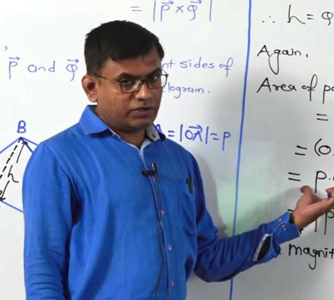
Page 26 :
Figure 1.16 shows a rigid laminar object able, to rotate about three mutually perpendicular, axes x, y and z. Axes x and y are in the plane, of the object while the z axis is perpendicular, to it, and all are concurrent at O. Consider a, mass element dm located at any point P. PM, = y and PN = x are the perpendiculars drown, from P respectively on the x and y axes. The, respective perpendicular distances of point, P from x, y and z axes will then be y, x and, � y 2 + x 2 . If Ix, Iy and Iz are the respective, moments of inertia of the body about x, y and, z axes, we can write,, � I x � � y 2 dm,��I y � � x 2 dm ���and �, , �, , (II) Consider any two mutually perpendicular, diameters x and y of the flywheel. If the, flywheel rotates about these diameters, these, three axes (own axis and two diameters) will, be mutually perpendicular and concurrent., Thus, perpendicular axes theorem is, applicable. Let Id be the moment of inertia, of the flywheel, when rotating about its, diameter. � I d � I x � I y, Thus, according to the theorem of, perpendicular axes,, 1, I z � MR 2 � I x � I y � 2 I d, 2, 1, � I d � MR 2, 4, , �, , I z � � y 2 � x 2 dm, , � I z � � y 2 dm � � x 2 dm � I x � I y, , This is the mathematical form of the, theorem of perpendicular axes., It states that, “The moment of inertia, (Iz) of a laminar object about an axis (z), perpendicular to its plane is the sum of its, moments of inertia about two mutually, perpendicular axes (x and y) in its plane, all, the three axes being concurrent”., , As the diameter passes through the centre, of mass of the (uniform) disc, I d = I C, Consider a tangent in the plane of the disc, and parallel to this diameter. It is at the, distance h = R from the diameter. Thus,, parallel axes theorem is applicable about, these two axes., ∴ IT, parallel = Io = Ic + Mh2 = Id + MR2, 1, 5, =, MR2 + MR2 = MR2, 4, 4, 5, 5, ∴ IT, parallel = MR2 = 20 × 0.252, 4, 4, = 1.5625 kg m2, , Example 1.7: A flywheel is a mechanical, device specifically designed to efficiently, store rotational energy. For a particular, machine it is in the form of a uniform 20 kg, disc of diameter 50 cm, able to rotate about, its own axis. Calculate its kinetic energy, 2, when rotating at 1200 rpm. Use � � 10.�, Calculate its moment of inertia, in case it is, rotated about a tangent in its plane., Solution: (I) As the flywheel is in the form, of a uniform disc rotating about its own, 1, axis, I z = MR 2, 2, ∴ Rotational kinetic energy, 1, 1�1, �, � � I � 2 � � MR 2 � 4� 2 n 2 �, 2, 2� 2, �, ∴ Rotational kinetic energy, , 1.8 Angular Momentum or Moment of, Linear Momentum:, The quantity in rotational mechanics,, analogous to linear momentum is angular, momentum or moment of linear momentum. It, is similar to the torque being moment of a force., , If p is the instantaneous linear momentum of, a particle undertaking a circular motion, its, , � M� 2 � Rn � � 20 � 10 � � 0.25 � 20 � � 5000 �J, 2, , 2, , 16
Page 27 :
axis of rotation. The expression for angular, momentum L = I ω is analogous to the, expression p = mv of linear momentum, if the, moment of inertia I replaces mass, which is, its physical significance., 1.9 Expression for Torque in Terms of, Moment of Inertia:, , angular, at that instance is given by, momentum, , L � r � p , were r is the position vector from, the axis of rotation., In magnitude, it is the product of linear, momentum and its perpendicular distance from, the axis of rotation. ∴L = P × r sin θ , where θ, is, angle between the directions of, �� the smaller, , P and r ., 1.8.1 Expression for Angular Momentum in, Terms of Moment of Inertia:, Figure 1.12 in the section 1.5 shows a, rigid object rotating with a constant angular, speed ω about an axis perpendicular to the, plane of paper. For theoretical simplification, let us consider the object to be consisting of, N number of particles of masses m1, m2, ….., mN at respective perpendicular distances r1, r2,, …..rN from the axis of rotation. As the object, rotates, all these particles perform UCM with, same angular speed ω , but with different linear, speeds v1 = r1 ω , v2 = r2 ω , ..... vN = rN ω . , Directions of individual velocities v1 ,, , v 2 , etc., are along the tangents to their, respective tracks. Linear momentum of the, first particle is of magnitude p1 = m1v1 = m1r1 ω ., , Its direction is along that of v1 ., Its angular momentum is thus of, 2, magnitude L1 = p1r1 � m1r1 �, Similarly, L2 � m2 r22� , L3 � m3 r32� , ……., LN � mN rN2�, For a rigid body with a fixed axis of, rotation, all these angular momenta are directed, along the axis of rotation, and this direction, can be obtained by using right hand thumb, rule. As all of them have the same direction,, their magnitudes can be algebraically added., Thus, magnitude of angular momentum of the, body is given by, L � m1r12� � m2 r22� ��� mN rN2�, , �, , Fig 1.17: Expression for torque., , Figure 1.17 shows a rigid object rotating, with a constant angular acceleration α, about an axis perpendicular to the plane, of paper. For theoretical simplification let, us consider the object to be consisting of N, number of particles of masses m1, m2, ….. mN, at respective perpendicular distances r1, r2,, …..rN from the axis of rotation. As the object, rotates, all these particles perform circular, motion with same angular acceleration α, but, with different linear (tangential) accelerations, a1 � r1� ,�a 2 � r2� ,���, a N � rN� , etc., Force experienced by the first particle is, f 1 � m1a1 � m1r1�, As these forces are tangential, their, respective perpendicular distances from the, axis are r1, r2, …..rN., Thus, the torque experienced by the first, 2, particle is of magnitude � 1 � f 1r1 � m1r1 �, Similarly, � 2 � m2 r22� , � 3 � m3 r32� …….., � N � mN rN2�, If the rotation is restricted to a single, plane, directions of all these torques are the, same, and along the axis. Magnitude of the, resultant torque is then given by, � � � 1 � � 2 ��� � N, , �, , � m1r12 � m2 r22 ��� mN rN2 � � I �, Where, I � m1r12 � m2 r22 ��� mN rN2 is the, moment of inertia of the body about the given, , �, , �, , � m1r12 � m2 r22 �� mN rN2 � � I �, 17
Page 28 :
Examples of conservation of angular, momentum: During some shows of ballet, dance, acrobat in a circus, sports like ice, skating, diving in a swimming pool, etc., the, principle of conservation of angular momentum, is realized. In all these applications the product, L � I � � I � 2� n � is constant (once the players, acquire a certain speed). Thus, if the moment, of inertia I is increased, the angular speed and, hence the frequency of revolution n decreases., Also, if the moment of inertia is decreased, the, frequency increases., (i) Ballet dancers: During ice ballet, the, dancers have to undertake rounds of smaller, and larger radii. The dancers come together, while taking the rounds of smaller radius (near, the centre). In this case, the moment of inertia, of their system becomes minimum and the, frequency increases, to make it thrilling. While, outer rounds, the dancers outstretch their legs, and arms. This increases their moment of, inertia that reduces the angular speed and, hence the linear speed. This is essential to, prevent slipping., (ii) Diving in a swimming pool (during, competition): While on the diving board, the, divers stretch their body so as to increase the, moment of inertia. Immediately after leaving, the board, they fold their body. This reduces, the moment inertia considerably. As a result,, the frequency increases and they can complete, more rounds in air to make the show attractive., Again, while entering into water they stretch, their body into a streamline shape. This allows, them a smooth entry into the water., , 2, 2, 2, where, I � m1r1 � m2 r2 �� mN rN is the, moment of inertia of the object about the given, axis of rotation., The relation � � I � is analogous to, f = ma for the translational motion if the, moment of inertia I replaces mass, which is, its physical significance., 1.10 Conservation of Angular Momentum:, In the article 4.7 of XIth Std. we have, seen the conservation of linear momentum, which says that linear momentum of an, isolated system is conserved in the absence, of an external unbalanced force. As seen, earlier, torque and angular momentum are, the respective analogous quantities to force, and linear momentum in rotational dynamics., With suitable changes this can be transformed, into the conservation of angular momentum., As seen in the section 1.8, angular, momentum or the moment of linear momentum, , of a system is given by L � r � p, , where r is the position vector from the axis of, , rotation and p is the linear momentum., Differentiating with respect to time, we get,, , , , dL d , dp dr , � �r � p� � r � � � p, dt dt, �d�t dt, , dr , d p ��, Now,, = v � and, =F ., d, d, t, t, , , dL, , �, � r � F � m v�v, dt, , Now v � v � 0, , dL , �, �r�F, dt, , , But r × F, is the moment of force or torque τ ., dL, �� �, , dt, , dL, , Thus, if � � 0,�� � 0 �or �L � constant.�, dt, ��, Hence, angular momentum L is conserved in, , the absence of external unbalanced torque τ ., This is the principle of conservation of angular, momentum, analogous to the conservation of, linear momentum., , �, , �, , �, , �, , Example 1.8: A spherical water balloon is, rotating at 60 rpm. In the course of time,, 48.8 % of its water leaks out. With what, frequency will the remaining balloon rotate, now? Neglect all non-conservative forces., 3, , 1, , m V �R �, �, �3, Solution: 1 � 1 � � 1 � � R1 � � m1 �, m2 V2 � R2 �, R2 � m2 �, 18
Page 29 :
Also,, , Accordingly, the object possesses two, types of kinetic energies, rotational and, translational. Sum of these two is its total, kinetic energy., Consider an object of moment of inertia, I, rolling uniformly. Following quantities can, be related., v = Linear speed of the centre of mass, R = Radius of the body, � � Angular speed of rotation of the body, v, �� � for any particle, R, M = Mass of the body, K = Radius of gyration of the body � I � MK 2, Total kinetic energy of rolling = Translational, K.E. + Rotational K.E., 1, 1, � E � Mv 2 � I � 2, 2, 2, , m1, 100, 100, 1, �, �, �, �, m2 100 � 48.8 51.2 0.512, 1, , � m �3, 1, �� 1 � �, � 1.25, 0.8, � m2 �, , =, n1 60, =, �rpm 1�rps, ����������n2 = ?, Being sphere, moment of inertia, 2, , 5, , I � m �� R � � m �3, 2, I � mR 2 � 1 � � 1 � � 1 � � � 1 �, 5, I 2 � m2 � � R2 � � m2 �, According to principle of conservation of, angular momentum, I1�1 � I 2�2, 5, , �I �, � m �3, � I1 2� n1 � I 2 2� n2 � n2 � � 1 � n1 � � 1 �, � I2 �, � m2 �, n1 � �1.225 � � 1 � 3.052 �rps, Example 1.9: A ceiling fan having moment, of inertia 2 kg-m2 attains its maximum, frequency of 60 rpm in ‘2π’ seconds., Calculate its power rating., Solution:, �0 � 0, �� � 2� n � 2� � 2 � 4� �rad / s, � � �0 4� � 0, ��, �, � 2 rad/s2, t, 2�, � P � � � � � I � � � � 2 � 2 � 4�, 5, , 2, , 1, 1, �v�, � Mv 2 � MK 2 � �, 2, 2, �R�, � K2 �, 1, � Mv 2 � 1 � 2 �, --- (1.18), R �, 2, �, It must be remembered that static friction, is essential for a purely rolling motion. In this, case, it prevents the sliding motion. You might, have noticed that many a times while rolling, down, the motion is initially a purely rolling, motion that later on turns out to be a sliding, motion. Similarly, if you push a sphere-like, object along a horizontal surface, initially it, slips for some distance and then starts rolling., 1.11.1 Linear Acceleration and Speed While, Pure Rolling Down an Inclined Plane:, Figure 1.18 shows a rigid object of mass, M and radius R, rolling down an inclined plane,, without slipping. Inclination of the plane with, the horizontal is θ ., , �, , � 16� �watt � 50 �watt, 1.11 Rolling Motion:, The objects like a cylinder, sphere,, wheels, etc. are quite often seen to perform, rolling motion. In the case of pure rolling,, two motions are undertaking simultaneously;, circular motion and linear motion. Individual, motion of the particles (except the one at the, centre of mass) is too difficult to describe., However, for theory considerations we can, consider the actual motion to be the result of, (i) rotational motion of the body as a whole,, about its own symmetric axis and, (ii) linear motion of the body assuming it to, be concentrated at its centre of mass. In other, words, the centre of mass performs purely, translational motion., , �, , Fig. 1.18: Rolling along an incline., , 19
Page 30 :
As the objects starts rolling down, its, gravitational P.E. is converted into K.E. of, rolling. Starting from rest, let v be the speed of, the centre of mass as the object comes down, through a vertical distance h., From Eq. (1.18),, 1, 1 2 1, K2 �, 2, 2�, E � Mv � I � � Mv � 1 � 2 �, 2, 2, 2, R �, �, 2, �, 1, K �, � E � Mgh � Mv 2 � 1 � 2 � �, 2, R �, �, , 1, K2, = �for�a uniform disc or a solid cylinder, 2, 2, R, 2, 2, K, = �for a thin walled hollow sphere, 2, 3, R, (II) When a rod rolls, it is actually a cylinder, that is rolling., (III) While rolling, the ratio ‘Translational, , 2 gh, �v �, � K2 �, --- (1.19), �1 � 2 �, R, �, �, Linear distance travelled along the plane, h, is s �, sin �, During this distance, the linear velocity, has increased from zero to v. If a is the linear, acceleration along the plane,, 2 gh, � h �, � 2a �, � 0�, �, 2as � v 2 � u 2 �, �, 2, � sin � � � K �, �1 � 2 �, R �, �, g sin �, �a �, � K2 �, � 1 � 2 � --- (1.20), R �, �, For pure sliding, without friction, the, acceleration is g sin θ and final velocity is, , K2 2, For example, for a hollow sphere, 2 =, R, 3, Thus, for a rolling hollow sphere,, , K.E.: Rotational K.E.: Total K.E.’ is, 2, , 1: K, R2, , � K2 �, : �1 � 2 �, R �, �, , Translational K.E.: Rotational K.E.: Total, 2, 2, K.E. = 1: : �� 1 � �� � 3 : 2 : 5, 3 � 3�, Percentage wise, 60% of its kinetic energy, is translational and 40% is rotational., Table 1.1 : Analogous kinematical equations, (ω0 is the initial angular velocity), , Equation for, translational, motion, v av �, , u�v, 2, , dv v � u, �, �, t, dt, � v � u � at, a�, , 2gh . Thus, during pure rolling, the factor, � K2 �, � 1 � 2 � is effective for both the expressions., R �, �, , s � v av � t, , Analogous equation, for rotational, motion, , �av �, , d� � � �0, �, dt, t, � � � �0 � � t, , ��, , � � �av � t, �� �� �, �� 0, �t, � 2 �, 1, � �0 t � � t 2, 2, , �u�v�, ��, �t, � 2 �, 1, � ut � at 2, 2, , Remarks :, I) For a rolling object, if the expression for, moment of inertia is of the form n (MR2), the, K2, numerical factor n gives the value of 2 for, R, that object., , v 2 � u 2 � 2as, , For example, for a uniform solid sphere,, 2, K2 2, I � MR 2 � MK 2 �� 2 �, 5, R, 5, Similarly,, K2, = 1, for�a�ring�or�a�hollow�cylinder, R2, , �0 � �, 2, , � 2 � �02 � 2��, , Internet my friend, http://hyperphysics.phy-astr.gsu.edu/hbase/, mi.html, https://issacphysics.org, https://www.engineeringtoolbox.com, https://opentextbc.ca/physicstextbook, 20
Page 31 :
Table 2: Analogous quantities between translational motion and rotational motion:, , Translational motion, Symbol/, Quantity, expression, , Linear, s, displacement, , Rotational motion, Symbol/, Quantity, expression, , Angular, θ, displacement, �, �� d�, Angular velocity, ��, dt, ��, �� d �, Angular, ��, acceleration, dt, , , ds, v=, dt, , dv, a=, dt, , Linear velocity, Linear, acceleration, , Rotational inertia, or moment of, inertia, Angular, momentum, , m, , Inertia or mass, , ��, �, p = mv, , Linear, momentum, , ��, �� d p, f =, dt, , Force, , Torque, , , W � f �s, , Work, , P�, , Power, , I, , , v ���r, , , � � a �r, I � �r 2 dm � �mi ri 2, , ��, ��, L � I�, , , L�r�p, , ��, � dL, ��, dt, , , � �r� f, , , W � � ��, , Work, , dW , � f �v, dt, , Inter-relation,, if possible, , s �� �r, , P�, , Power, , ------, , dW , � � ��, dt, , ------, , Table 3: Expressions for moment of inertias for some symmetric objects:, , Object, , Axis, , Expression of, moment of inertia, , Thin ring or, hollow cylinder, , Central, , I = MR 2, , Thin ring, , Diameter, , Annular ring or, thick walled, hollow cylinder, , Central, , I=, , I�, , 21, , 1, MR 2, 2, , 1, M r22 � r12, 2, , �, , �, , Figure
Page 32 :
Uniform disc or, solid cylinder, , Central, , I=, , 1, MR 2, 2, , Uniform disc, , Diameter, , I=, , 1, MR 2, 4, , Thin walled, hollow sphere, , Central, , I=, , 2, MR 2, 3, , Solid sphere, , Central, , I=, , 2, MR 2, 5, , �, �, , r25 � r15, 2, I� M 3 3, 5, r2 � r1, , Uniform symmetric, spherical shell, , Central, , Thin uniform rod or, rectangular plate, , Perpendicular to, length and passing, through centre, , I=, , 1, ML2, 12, , Thin uniform rod or, rectangular plate, , Perpendicular to, length and about, one end, , I=, , 1, MR 2, 3, , Uniform plate, , or rectangular, , I�, , Central, , parallelepiped, , 22, , �, �, , 1, M ( L2 � b 2 ), 12
Page 33 :
Uniform solid, right circular cone, , Central, , I=, , 3, MR 2, 10, , Uniform hollow, right circular cone, , Central, , I=, , 1, MR 2, 2, , Exercises, formula (expression) of moment of, inertia (M.I.) in terms of mass M of, the object and some of its distance, parameter/s, such as R, L, etc., , (A) Different objects must have different, expressions for their M.I., , (B) When rotating about their central, axis, a hollow right circular cone and, a disc have the same expression for, the M.I., , (C) Expression for the M.I. for a, parallelepiped rotating about the, transverse axis passing through its, centre includes its depth., , (D) Expression for M.I. of a rod and, that of a plane sheet is the same, about a transverse axis., iv) In a certain unit, the radius of gyration, of a uniform disc about its central and, transverse axis is 2.5 . Its radius of, gyration about a tangent in its plane (in, the same unit) must be, , (A) 5 (B) 2.5 , (C) 2 2.5, (D) 12.5, v), Consider following cases:, (P) A planet revolving in an elliptical orbit., (Q) A planet revolving in a circular orbit., Principle of conservation of angular, momentum comes in force in which of, these?, , Use g = 10 m/s2, unless, otherwise stated., 1. Choose the correct option., i), When seen from below, the blades of, a ceiling fan are seen to be revolving, anticlockwise and their speed is, decreasing. Select correct statement, about the directions of its angular, velocity and angular acceleration., , (A) Angular velocity upwards, angular, acceleration downwards., (B) Angular velocity downwards,, angular acceleration upwards., , (C) Both, angular velocity and angular, acceleration, upwards., (D), Both, angular velocity and, angular acceleration, downwards., ii) A particle of mass 1 kg, tied to a 1.2 m, long string is whirled to perform vertical, circular motion, under gravity. Minimum, speed of a particle is 5 m/s. Consider, following statements., P) Maximum speed must be 5 5 m/s., Q) Difference between maximum and, minimum tensions along the string is 60 N., , Select correct option., , (A) Only the statement P is correct., , (B) Only the statement Q is correct., , (C) Both the statements are correct., , (D) Both the statements are incorrect., iii) Select correct statement about the, 23
Page 34 :
(A) Only for (P), (B) Only for (Q), (C) For both, (P) and (Q), , (D) Neither for (P), nor for (Q), X) A thin walled hollow cylinder is rolling, down an incline, without slipping. At, any instant, the ratio ”Rotational K.E.:, Translational K.E.: Total K.E.” is, , (A) 1:1:2, (B) 1:2:3 , (C) 1:1:1, (D) 2:1:3, 2. Answer in brief., i), Why are curved roads banked?, ii) Do we need a banked road for a twowheeler? Explain., iii) On what factors does the frequency, of a conical pendulum depend? Is it, independent of some factors?, iv) Why is it useful to define radius of, gyration?, v) A uniform disc and a hollow right, circular cone have the same formula, for their M.I., when rotating about their, central axes. Why is it so?, 3. While driving along an unbanked, circular road, a two-wheeler rider has, to lean with the vertical. Why is it so?, With what angle the rider has to lean?, Derive the relevant expression. Why, such a leaning is not necessary for a four, wheeler?, 4. Using the energy conservation, derive, the expressions for the minimum speeds, at different locations along a vertical, circular motion controlled by gravity., Is zero speed possible at the uppermost, point? Under what condition/s? Also, prove that the difference between the, extreme tensions (or normal forces), depends only upon the weight of the, object., 5. Discuss the necessity of radius of, gyration. Define it. On what factors does, it depend and it does not depend? Can, you locate some similarity between the, centre of mass and radius of gyration?, , 6., , 7., , 8., , 9., , 10., , 11., , 12., , 13., , 24, , What can you infer if a uniform ring and, a uniform disc have the same radius of, gyration?, State the conditions under which, the theorems of parallel axes and, perpendicular axes are applicable. State, the respective mathematical expressions., Derive an expression that relates angular, momentum with the angular velocity of, a rigid body., Obtain an expression relating the torque, with angular acceleration for a rigid, body., State and explain the principle of, conservation of angular momentum. Use, a suitable illustration. Do we use it in our, daily life? When?, Discuss, the, interlink, between, translational, rotational and total kinetic, energies of a rigid object that rolls, without slipping., A rigid object is rolling down an, inclined plane. Derive expressions for, the acceleration along the track and, the speed after falling through a certain, vertical distance., Somehow, an ant is stuck to the rim of a, bicycle wheel of diameter 1 m. While the, bicycle is on a central stand, the wheel, is set into rotation and it attains the, frequency of 2 rev/s in 10 seconds, with, uniform angular acceleration. Calculate, (i) Number of revolutions completed by, the ant in these 10 seconds. (ii) Time, taken by it for first complete revolution, and the last complete revolution., =, 10 �s, �t last 0.5132 �s ], [Ans:10=, rev., tfirst, Coefficient of static friction between, a coin and a gramophone disc is 0.5., Radius of the disc is 8 cm. Initially the, centre of the coin is 2 cm away from, the centre of the disc. At what minimum, frequency will it start slipping from
Page 35 :
motorcycle varies between 6 m/s and 10, m/s. Calculate diameter of the sphere of, death. What are the minimum values are, possible for these two speeds?, , [Ans: Diameter = 3.2 m,, , (v1)min = 4 m/s, (v2)min = 4 5 �m / s ], 19. A metallic ring of mass 1 kg has moment, of inertia 1 kg m2 when rotating about, one of its diameters. It is molten and, remoulded into a thin uniform disc of the, same radius. How much will its moment, of inertia be, when rotated about its own, axis., , [Ans: 1 kg m2], 20. A big dumb-bell is prepared by using, a uniform rod of mass 60 g and length, 20 cm. Two identical solid thermocol, spheres of mass 25 g and radius 10 cm, each are at the two ends of the rod., Calculate moment of inertia of the dumbbell when rotated about an axis passing, through its centre and perpendicular to, the length., , [Ans: 24000 g cm-2], 21. A flywheel used to prepare earthenware, pots is set into rotation at 100 rpm. It is, in the form of a disc of mass 10 kg and, radius 0.4 m. A lump of clay (to be taken, equivalent to a particle) of mass 1.6 kg, falls on it and adheres to it at a certain, distance x from the centre. Calculate x if, the wheel now rotates at 80 rpm., 1, =, x =, �m 0.35 �m ], , [Ans:, 8, 22. Starting from rest, an object rolls down, along an incline that rises by 3 units, in every 5 units (along it). The object, gains a speed of 10 m/s as it travels a, 5, distance of m along the incline. What, 3, can be the possible shape/s of the object?, K2, , [Ans: 2 = 1. Thus, a ring or, R, a hollow cylinder], , there? By what factor will the answer, change if the coin is almost at the rim?, (use g = π2 m/s2), 1, , [Ans: 2.5 rev/s, n2 = n1 ], 2, 14. Part of a racing track is to be designed, for a radius of curvature of 72 m. We are, not recommending the vehicles to drive, faster than 216 kmph. With what angle, should the road be tilted? At what height, will its outer edge be, with respect to the, inner edge if the track is 10 m wide?, [Ans: � � tan �1 ( 5) � 78.69 o ,�h � 9.8 �m ], 15. The road in the example 14 above is, constructed as per the requirements. The, coefficient of static friction between the, tyres of a vehicle on this road is 0.8, will, there be any lower speed limit? By how, much can the upper speed limit exceed in, this case?, , [Ans: vmin ≅ 88�kmph , no upper limit as, the road is banked for � � 45o ], 16. During a stunt, a cyclist (considered to, be a particle) is undertaking horizontal, circles inside a cylindrical well of, radius 6.05 m. If the necessary friction, coefficient is 0.5, how much minimum, speed should the stunt artist maintain?, Mass of the artist is 50 kg. If she/he, increases the speed by 20%, how much, will the force of friction be?, f s mg, = 500�N ], , [Ans: vmin = 11 m/s, =, 17. A pendulum consisting of a massless, string of length 20 cm and a tiny bob, of mass 100 g is set up as a conical, pendulum. Its bob now performs 75 rpm., Calculate kinetic energy and increase in, the gravitational potential energy of the, bob. (Use � 2 � 10 ), , [Ans: cos � � 0.8, K.E. = 0.45 J,, � � P.E � � 0.04 J], 18. A motorcyclist (as a particle) is, undergoing vertical circles inside, a sphere of death. The speed of the, 25
Page 36 :
2. Mechanical Properties of Fluids, A fluid flows under the action of a force, or a pressure gradient. Behaviour of a fluid, in motion is normally complicated. We can, understand fluids by making some simple, assumptions. We introduce the concept of an, ideal fluid to understand its behaviour. An, ideal fluid has the following properties:, 1. It is incompressible: its density is constant., 2. Its flow is irrotational: its flow is smooth,, there are no turbulences in the flow., 3. It is nonviscous: there is no internal friction, in the flow, i.e., the fluid has no viscosity., (viscosity is discussed in section 2.6.1), 4. Its flow is steady: its velocity at each point, is constant in time., It is important to understand the difference, between a solid and a fluid. Solids can be, subjected to shear stress (tangential stress) as, shown in Fig. 2.1 and normal stress, as shown, in Fig.2.2., , Can you recall?, 1. How important are fluids in our life?, 2. What is atmospheric pressure?, 3. Do you feel excess pressure while, swimming under water? Why?, 2.1 Introduction:, In XIth Std. we discussed the behaviour of, solids under the action of a force. Among three, states of matter, i.e., solid, liquid and gas, a, solid nearly maintains its fixed shape and, volume even if a large force is applied to it., Liquids and gases do not have their own shape, and they take the shape of the containing, vessel. Due to this, liquids and gases flow under, the action of external force. A fluid means a, substance that can flow. Therefore, liquids and, gases, collectively, are called fluids. A fluid, either has no rigidity or its rigidity is very low., In our daily life, we often experience, the pressure exerted by a fluid at rest and in, motion. Viscosity and surface tension play, an important role in nature. We will try to, understand such properties in this chapter., 2.2 Fluid:, Any substance that can flow is a, fluid. A fluid is a substance that deforms, continually under the action of an external, force. Fluid is a phase of matter that, includes liquids, gases and plasmas., , Fig. 2.1: Shear stress., , Do you know?, Plasma is one of the four fundamental states, of matter. It consists of a gas of ions, free, electrons and neutral atoms., , (a) Compressive , , (b) Tensile, , Fig. 2.2: Normal stress., , Solids oppose the shear stress either by, developing a restoring force, which means that, the deformations are reversible, or they require, a certain initial stress before they deform and, start flowing. (We have studied this behavior, of solids (elastic behaviour) in XIth Std)., Ideal fluids, on the other hand, can only, be subjected to normal, compressive stress, (called pressure). Most fluids offer a very, , We shall discuss mechanical properties, of only liquids and gases in this Chapter. The, shear modulus of a fluid is zero. In simpler, words, fluids are substances which cannot, resist any shear force applied to them. Air,, water, flour dough, toothpaste, etc., are some, common examples of fluids. Molten lava is, also a fluid., 26
Page 37 :
weak resistance to deformation. Real fluids, display viscosity and so are capable of being, subjected to low levels of shear stress., , Figure 2.4 shows a fluid exerting normal, forces on a vertical surface and Fig. 2.5 shows, fluid exerting normal forces on a horizontal, surface., , Fig. 2.3: Forces acting on a small surface dA, within a fluid at rest., , Fig. 2.4: Fluid exerts force on vertical surface., , The Fig. 2.3 shows a small surface of, area dA at rest within a fluid. The surface does, not accelerate, so the surrounding fluid exerts, equal normal forces dF on both sides of it., Properties of Fluids:, 1. They do not oppose deformation, they get, permanently deformed., 2. They have ability to flow., 3. They have ability to take the shape of the, container., A fluid exhibits these properties because, it cannot oppose a shear stress when in, static equilibrium., , Fig. 2.5: Fluid exerts force on horizontal surface., , Thus, an object having small weight, can exert high pressure if its weight acts on a, small surface area. For example, a force of, 10 N acting on 1 cm2 results in a pressure of, 105 N m-2. On the other hand, the same force of, 10 N while acting on an area of 1 m2, exerts a, pressure of only 10 N m-2., , Remember this, , Remember this, , The term fluid includes both the liquid and gas, phases. It is commonly used, as a synonym, for liquid only, without any reference to gas., For example, ‘brake fluid’ is hydraulic oil, and will not perform its required function if, there is gas in it! This colloquial use of the, term is also common in the fields of medicine, and nutrition, e.g., “take plenty of fluids”., , 1 N weight is about 100 g mass, if, g =10 m s-2., The SI unit of pressure is N/m2. Also,, 1 N/m2 = 1 Pascal (Pa). The dimension of, pressure is [L-1M1T-2]. Pressure is a scalar, quantity. Other common units of measuring, pressure of a gas are bar and torr. One torr is, one mm of mercury column., 1 bar = 105 Nm-2, 1 hectapascal (hPa) = 100 Pa, , 2.2.1 Fluids at Rest:, The branch of physics which deals, with the properties of fluids at rest is called, hydrostatics. In the next few sections we will, consider some of the properties of fluids at rest., 2.3 Pressure:, A fluid at rest exerts a force on the surface, of contact. The surface may be a wall or the, bottom of an open container of the fluid. The, normal force (F) exerted by a fluid at rest per, unit surface area (A) of contact is called the, pressure (p) of the fluid., F, , --- (2.1), P=, A, , Can you tell?, Why does a knife have a sharp edge,, and a needle has a sharp tip?, Use your brain power, A student of mass 50 kg is standing on both, feet. Estimate the pressure exerted by the, student on the Earth. Assume reasonable, value to any other quantity you need. Justify, your assumption. You may use g = 10 m s-2, By what factor will it change if the student, lies on back?, 27
Page 38 :
Remember this, , Remember this, , The concept of pressure is useful in dealing, with fluids, i.e., liquids and gases. As fluids, do not have definite shape and volume, it, is convenient to use the quantities pressure, and density rather than force and mass when, studying hydrostatics and hydrodynamics., , 1. As p = hρg, the pressure exerted by a, fluid at rest is independent of the shape, and size of the container., 2. p = hρg is true for liquids as well as for, gases., Example 2.1: Two different liquids of, density ρ1 and ρ2 exert the same pressure at, a certain point. What will be the ratio of the, heights of the respective liquid columns?, Solution: Let h1 be the height of the liquid of, density ρ1. Then the pressure exerted by the, liquid of density ρ1 is p1 = h1ρ1g. Similarly,, let h2 be the height of the liquid of density, ρ2. Then the pressure exerted by the liquid, of density ρ2 is p2 = h2ρ2g., Both liquids exert the same pressure,, therefore we write,, p1 = p2, h1 � 2, �, h, ρ, g, =, h, ρ, g, or,, ∴ 1 1, 2 2, h2 �1, Alternate method:, For a given value of p = hρg = constant,, as g is constant. So the hight is inversely, proportional to the density of the fluid ρ. In, this case, since pressure is constant, height, is inversely proportional to density of the, liquid., Example 2.2: A swimmer is swimming in, a swimming pool at 6 m below the surface, of the water. Calculate the pressure on the, swimmer due to water above. (Density of, water = 1000 kg/m3, g = 9.8 m/s2), Solution: Given,, h = 6 m, ρ = 1000 kg/m3, g = 9.8 m/s2, p = hρg = 6 × 1000 × 9.8 = 5.88 × 10⁴ N/m2, (Which is nearly 0.6 times the atmospheric, pressure!), , 2.3.1 Pressure Due to a Liquid Column:, , Fig. 2.6: Pressure due to a liquid column., , A vessel is filled with a liquid. Let us, calculate the pressure exerted by an imaginary, cylinder of cross sectional area A inside the, container. Let the density of the fluid be ρ, and, the height of the imaginary cylinder be h as, shown in the Fig. 2.6. The liquid column exerts, a force F = mg, which is its weight, on the, bottom of the cylinder. This force acts in the, downward direction. Therefore, the pressure p, exerted by the liquid column on the bottom of, cylinder is,, F, P=, A, mg, ∴P=, A, Now, m = (volume of cylinder) x (density of, liquid), = (Ah) × ρ = Ahρ, � Ah� � g, �P�, A, p = hρg , --- (2.2), Thus, the pressure p due to a liquid of, density ρ at rest, and at a depth h below the, free surface is hρg., Note that the pressure dose not depend, on the area of the imaginary cylinder used to, derive the expression., , 2.3.2 Atmospheric Pressure:, Earth's atmosphere is made up of a fluid,, namely, air. It exerts a downward force due, to its weight. The pressure due to this force, is called atmospheric pressure. Thus, at any, point, the atmospheric pressure is the weight of, a column of air per unit cross section starting, 28
Page 39 :
from that point and extending to the top of the, atmosphere. Clearly, the atmospheric pressure, is highest at the surface of the Earth, i.e., at the, sea level, and decreases as we go above the, surface as the height of the column of air above, decreases. The atmospheric pressure at sea, level is called normal atmospheric pressure., The density of air in the atmosphere decreases, with increase in height and becomes negligible, beyond a height of about 8 km so that the, height of air column producing atmospheric, pressure at sea level can be taken to be 8 km., The region where gas pressure is less than, the atmospheric pressure is called vacuum., Perfect or absolute vacuum is when no matter,, i.e., no atoms or molecules are present., Usually, vacuum refers to conditions when the, gas pressure is considerably smaller than the, atmospheric pressure., 2.3.3 Absolute Pressure and Gauge Pressure:, Consider a tank filled with water as shown, in Fig. 2.7. Assume an imaginary cylinder of, horizontal base area A and height x1- x2 = h., x1 and x2 being the heights measured from a, reference point, height increasing upwards:, x1 > x2. The vertical forces acting on the, cylinder are:, ��, �, 1. Force F1 acts downwards at the top surface, of the cylinder, and is due to the weight of, the water, ��� column above the cylinder., 2. Force F2 acts upwards at the bottom, surface of the cylinder, and is due to the, water below the cylinder., 3. The gravitational force on the water, enclosed in the cylinder is mg, where m is, the mass of the water in the cylinder. As, the water is in static equilibrium, the forces, on the cylinder are balanced. The balance, of these forces in magnitude is written as,, F2= F1+ mg , --- (2.3), p1and p2 are the pressures at the top and, bottom surfaces of the cylinder respectively, due to the fluid. Using Eq. (2.1) we can write, F1 = p1A, and F2 = p2A, --- (2.4), Also, the mass m of the water in the cylinder, can be written as,, m = density × volume = ρV, --- (2.5), ∴m = ρA(x1-x2) , , Substituting Eq. (2.4) and Eq. (2.5) in Eq. (2.3), we get,, p2A = p1A + ρAg (x1- x2), p2 = p1 + ρg (x1- x2) , --- (2.6), This equation can be used to find the, pressure inside a liquid (as a function of, depth below the liquid surface) and also the, atmospheric pressure (as a function of altitude, or height above the sea level)., , Fig. 2.7: Pressure due to an imaginary cylinder, of fluid., , To find the pressure p at a depth h below, the liquid surface, let the top of an imaginary, cylinder be at the surface of the liquid. Let, this level be x1. Let x2 be some point at depth h, below the surface as shown in Fig. 2.8. Let p0, be the atmospheric pressure at the surface, i.e.,, at x1. Then, substituting x1 = 0, p1 = p0, x2 = -h,, and p2 = p in Eq. (2.6) we get,, p = p0+ hρg , --- (2.7), The above equation gives the total, pressure, or the absolute pressure p, at a depth, h below the surface of the liquid. The total, pressure p, at the depth h is the sum of:, 1. p0, the pressure due to the atmosphere,, which acts on the surface of the, liquid, and, 2. hρg, the pressure due to the liquid at depth, h., , Fig. 2.8. Pressure at a depth h below the surface, of a liquid., , 29
Page 40 :
base of the vessel B and the liquid from vessel, C would rise into the vessel B. However,, it is never observed. Equation 2.2 tells that, the pressure at a point depends only on the, height of the liquid column above it. It does, not depend on the shape of the vessel. In this, case, height of the liquid column is the same, for all the vessels. Therefore, the pressure of, liquid column in each vessel is the same and, the system is in equilibrium. That means the, liquid in vessel C does not rise in to vessel B., , In general, the difference between the, absolute pressure and the atmospheric pressure, is called the gauge pressure. Using Eq. (2.7),, gauge pressure at depth h below the liquid, surface can be written as,, p - p0 = hρg , --- (2.8), Eq. (2.8) is also applicable to levels above, the liquid surface. It gives the pressure at a, given height above a liquid surface, in terms, of the atmospheric pressure p0 (assuming that, the atmospheric density is uniform up to that, height)., To find the atmospheric pressure at a, distance d above the liquid surface as shown, in Fig. 2.9, we substitute x1 = d, p1 = p, x2 = 0,, p2 = p0 and ρ = ρair in Eq. (2.6) we get,, p = po - dρair g --- (2.9), , (a), , (b), Fig. 2.10: Hydrostatic paradox., , Consider Fig. 2.10 (b). The arrows indicate, the forces exerted against the liquid by the walls, of the vessel. These forces are perpendicular to, walls of the vessel at each point. These forces, can be resolved into vertical and horizontal, components. The vertical components act in, the upward direction. Weight of the liquid in, section B is not balanced and contibutes the, pressure at the base. Thus, it is no longer a, paradox!, 2.3.5 Pascal’s Law:, Pascal’s law states that the pressure, applied at any point of an enclosed fluid at, rest is transmitted equally and undiminished to, every point of the fluid and also on the walls of, the container, provided the effect of gravity is, neglected., , Fig. 2.9: Change of atmospheric pressure, with height., , Can you tell?, The figures show three containers filled, with the same oil. How will the pressures at, the bottom compare?, , (a), , (b) , , (c), , Experimental proof of Pascal’s law., Consider a vessel with four arms A, B, C,, and D fitted with frictionless, water tight, pistons and filled with incompressible fluid, as shown in the figure given. Let the area of, cross sections of A, B, C, and D be a, 2a, 3a,, and a/2 respectively. If a force F is applied, on the piston A, the pressure exerted on the, liquid is p = F/a. It is observed that the other, three pistons B, C, and D move outward., In order to keep these three pistons B, C,, , 2.3.4 Hydrostatic Paradox:, Consider the inter connected vessels, as shown in Fig. 2.10 (a). When a liquid is, poured in any one of the vessels, it is noticed, that the level of liquids in all the vessels is the, same. This observation is somewhat puzzling., It was called 'hydrostatics paradox' before, the principle of hydrostatics were completely, understood., One can feel that the pressure of the base, of the vessel C would be more than that at the, 30
Page 41 :
transmitted undiminished to the bigger piston, S2. A force F2 = pA2 will be exerted upwards, on it., �A �, F2 � F1 � 2 � , --- (2.10), � A1 �, Thus, F2 is much larger than F1. A heavy, load can be placed on S2 and can be lifted up, or moved down by applying a small force on, S1. This is the principle of a hydraulic lift., , and D in their original positions, forces 2F,, 3F, and F/2 respectively are required to be, applied on the pistons. Therefore, pressure, on the pistons B, C, and D is:, , Observe and discuss, Blow air in to a flat balloon using a cycle, pump. Discuss how Pascal’s principle is, applicable here., , 2F F, pB � = �, on B, =, 2a a, 3F F, on C, p=, and, �= �, C, 3a a, F/2 F, pD � = �, on D, =, a/2 a, , ii) Hydraulic brakes: Hydraulic brakes are, used to slow down or stop vehicles in motion., It is based on the same principle as that of a, hydraulic lift., Figure 2.12 shows schematic diagram, of a hydraulic brake system. By pressing the, brake pedal, the piston of the master cylinder, is pushed in forward direction. As a result,, the piston in the slave cylinder which has a, much larger area of cross section as compared, to that of the master cylinder, also moves in, forward direction so as to maintain the volume, of the oil constant. The slave piston pushes the, friction pads against the rotating disc, which, is connected to the wheel. Thus, causing a, moving vehicle to slow down or stop., , i.e. pB = pC = pD = p, this indicates that the, pressure applied on piston A is transmitted, equally and undiminished to all parts of the, fluid and the walls of the vessel., Applications of Pascal’s Law:, i) Hydraulic lift: Hydraulic lift is used to lift a, heavy object using a small force. The working, of this machine is based on Pascal’s law., , Fig. 2.11 Hydraulic Lift., , As shown in Fig. 2.11, a tank containing, a fluid is fitted with two pistons S1 and S2 . S1, has a smaller area of cross section, A1 while, S2 has a much larger area of cross section,, A2 (A2 >> A1). If we apply a force F1 on the, smaller piston S1 in the downward direction it, will generate pressure p = (F1/A1) which will be, , Fig. 2.12 Hydraulic brake system (schematic)., , The master cylinder has a smaller area of, cross section A1 compared to the area A2 of the, slave cylinder. By applying a small force F1, 31
Page 42 :
i) Mercury Barometer: An instrument that, measures atmospheric pressure is called a, barometer. One of the first barometers was, invented by the Italian scientist Torricelli., The barometer is in the form of a glass tube, completely filled with mercury and placed, upside down in a small dish containing, mercury. Its schematic diagram is shown in, Fig. 2.13., , to the master cylinder, we generate pressure, p = (F1/A1). This pressure is transmitted, undiminished throughout the system. The force, F2 on slave cylinder is then,, �A �, F, F2 � �PA2 � � 1 � A2 � �F1 � 2 �, A1, � A1 �, This is similar to the principle used in, hydraulic lift. Since area A2 is greater than A1,, F2 is also greater than F1. Thus, a small force, applied on the brake pedal gets converted into, large force and slows down or stops a moving, vehicle., Example 2.3: A hydraulic brake system, of a car of mass 1000 kg having speed of, 50 km/h, has a cylindrical piston of radius, of 0.5 cm. The slave cylinder has a radius, of 2.5 cm. If a constant force of 100 N is, applied on the brake what distance the car, will travel before coming to stop?, Solution: Given,, F1 = 100 N, A1 = π (0.5 × 10⁻²)2 m2,, A2 = π (2.5 × 10⁻²)2 m2, F2 = ?, By Pascal’s Principle,, F2 F1, =�, A2 A1 , 100 �� � ( 2.5 ���10 �2 ) 2, � 2500 N, F2 �, � ( 0.5 ��10, � �2 ) 2, Acceleration of the car =, , Torricelli’s vacuum, , Fig. 2.13: Mercury, barometer., , 1. A glass tube of about 1 meter length and, a diameter of about 1 cm is filled with, mercury up to its brim. It is then quickly, inverted into a small dish containing, mercury. The level of mercury in the glass, tube lowers as some mercury spills in the, dish. A gap is created between the surface, of mercury in the glass tube and the closed, end of the glass tube. The gap does not, contain any air and it is called Torricelli’s, vacuum. It does contain some mercury, vapors., 2. Thus, the pressure at the upper end of the, mercury column inside the tube is zero, i.e., pressure at point such as A is PA= zero., 3. Let us consider a point C on the mercury, surface in the dish and another point B, inside the tube at the same horizontal level, as that of the point C., 4. The pressure at C is equal to the, atmospheric pressure p0 because it is open, to atmosphere. As points B and C are at the, same horizontal level, the pressure at B is, also equal to the atmospheric pressure Po,, i.e. PB= Po., 5. Suppose the point B is at a depth h below, the point A and ρ is the density of mercury, then,, PB= PA + hρg --- (2.11), , a = F2 /m = 2500/1000 = 2.5 m/s2. Using, Newton's equation of motion,, v2 = u2 -2as where final velocity v = 0,, u = 50 km/h, 2, , 1, � 50 � 1000 �, �, � 38.58 m, s��, �, � 3600 � ( 2 � 2.5), , 2.3.6 Measurement of Pressure:, Instruments used to measure pressure are, called pressure meters or pressure gauges or, vacuum gauges. Below we will describe two, instruments which are commonly used to, measure pressure., Caution:, Use of mercury is not advised in a, laboratory because mercury vapours are, hazardous for life and for environment., 32
Page 43 :
pressure at C is the same as at D, i.e., inside, the chamber. Therefore, the pressure p in the, container is,, p = pC , Using Eq. (2.12) and Eq. (2.13) we can write,, p = p0 + hρg --- (2.14), As the manometer measures the gauge, pressure of the gas in the container D, we can, write the gauge pressure in the container D as, p - p0 = hρg, , pA = 0 (there is vacuum above point A) and, pB = p0, therefore, p0 = hρg, where h is the length, of mercury column in the mercury barometer., Remember this, The atmospheric pressure is generally, expressed as the length of mercury column in, a mercury barometer., Patm= 76 cm of Hg = 760 mm of Hg =760, Torr., , Can you recall?, Can you tell?, , 1. You must have blown soap bubbles in, your childhood. What is their shape?, 2. Why does a greased razor blade float, on the surface of water?, 3. Why can a water spider walk, comfortably on the surface of still, water?, 4. Why are free liquid drops and bubbles, always spherical in shape?, , What will be the normal atmospheric, pressure in bar and also in torr?, ii) Open tube manometer: A manometer, consists of a U – shaped tube partly filled with, a low density liquid such as water or kerosene., This helps in having a larger level difference, between the level of liquid in the two arms of, the manometer. Figure 2.14 shows an open, tube manometer. One arm of the manometer, is open to the atmosphere and the other is, connected to the container D of which the, pressure p is to be measured., , 2.4 Surface Tension:, A liquid at rest shows a very interesting, property called surface tension. We have, seen that water spider walks on the surface, of steady water, greased needle floats on the, steady surface of water, rain drops and soap, bubbles always take spherical shape, etc., All these phenomena arise due to surface, tension. Surface tension is one of the important, properties of liquids., , Fig. 2.14 Open tube, manometer., , Do you know?, , The pressure at point A is atmospheric, pressure p0 because this arm is open to, atmosphere. To find the pressure at point C,, which is exposed to the pressure of the gas, in the container, we consider a point B in the, open arm of the manometer at the same level, as point C. The pressure at the points B and C, is the same, i.e.,, pC = pB --- (2.12), The pressure at point B is,, pB = po + hρg --- (2.13), where, ρ is the density of the liquid in the, manometer, h is the height of the liquid column, above point B, and g is the acceleration due, to gravity. According to Pascal’s principle,, , 1. When we write on paper, the ink sticks, to the paper., 2. When teacher writes on a board, chalk, particles stick to the board., 3. Mercury in a glass container does not, wet its surface, while water in a glass, container wets it., 2.4.1 Molecular Theory of Surface Tension:, All the above observations can be, explained on the basis of different types of, forces coming into play in all these situations., We will try to understand the effect of these, forces and their relation to the surface tension, in liquids., 33
Page 44 :
To understand surface tension, we need, to know some terms in molecular theory, that explain the behaviour of liquids at their, surface., a) Intermolecular force: Matter is made up, of molecules. Any two molecules attract each, other. This force between molecules is called, intermolecular force. There are two types of, intermolecular forces - i) Cohesive force and, ii) Adhesive force., i) Cohesive force: The force of attraction, between the molecules of the same, substance is called cohesive force or, force of cohesion. The force of attraction, between two air molecules or that between, two water molecules is a cohesive force., Cohesive force is strongest in solids and, weakest in gases. This is the reason why, solids have a definite shape and gases do, not. Small droplets of liquid coalesce into, one and form a drop due to this force., ii) Adhesive force: The force of attraction, between the molecules of different, substances is called adhesive force or, force of adhesion. The force of attraction, between glass and water molecule is a, force of adhesion., b) Range of molecular force: The maximum, distance from a molecule up to which the, molecular force is effective is called the range, of molecular force. Intermolecular forces, are effective up to a distance of the order of, few nanometer (10-9 m) in solids and liquids., Therefore, they are short range forces., c) Sphere of influence: An imaginary sphere, with a molecule at its center and radius equal, to the molecular range is called the sphere of, influence of the molecule. The spheres around, molecules A, B or C are shown in Fig. 2.15 (a), and (b). The intermolecular force is effective, only within the sphere of influence., d) Surface film: The surface layer of a, liquid with thickness equal to the range of, intermolecular force is called the surface film., This is the layer shown between XY and X′Y′, in Fig. 2.15 (b)., , (a), , (b), Fig. 2.15: (a) sphere of influence and, (b) surface film., , (e) Free surface of a liquid: It is the surface, of a fluid which does not experience any shear, stress. For example, the interface between, liquid water and the air above. In Fig. 2.15 (b),, XY is the free surface of the liquid., Remember this, While studying pressure, we considered both, liquids and gases. But as gases do not have, a free surface, they do not exhibit surface, tension., (f) Surface tension on the basis of molecular, theory: As shown in Fig. 2.15 (b), XY is the, free surface of liquid and X′Y′ is the inner, layer parallel to XY at distance equal to the, range of molecular force. Hence, the section, XX′-Y′Y near the surface of the liquid acts as, the surface film. Consider three molecules A,, B, and C such that molecule A is deep inside, the liquid, molecule B within surface film and, molecule C on the surface of the liquid., As molecule A is deep inside the liquid, its, sphere of influence is also completely inside, the liquid. As a result, molecule A is acted, upon by equal cohesive forces in all directions., Thus, the net cohesive force acting on molecule, A is zero., Molecule B lies within the surface layer, and below the free surface of the liquid. A, larger part of its sphere of influence is inside, the liquid and a smaller part is in air. Due to, this, a strong downward cohesive force acts on, the liquid molecule. The adhesive force acting, on molecule B due to air molecules above it, and within its sphere of influence is weak. It, points upwards. As a result, the molecule B, gets attracted inside the liquid., 34
Page 45 :
The same holds for molecule C which lies, exactly on the free surface of the liquid. Half, of the sphere of influence is in air and half in, the liquid. The number of air molecules within, the sphere of influence of the molecule C,, above the free surface of the liquid is much less, than the number of liquid molecules within the, sphere of influence that lies within the liquid., This is because, the density of air is less than, that of a liquid. The adhesive force trying to, pull the molecule above the liquid surface is, much weaker than the cohesive force that tries, to pull the molecule inside the liquid surface., As a result, the molecule C also gets attracted, inside the liquid., Thus, all molecules in the surface film, are acted upon by an unbalanced net cohesive, force directed into the liquid. Therefore, the, molecules in the surface film are pulled inside, the liquid. This minimizes the total number of, molecules in the surface film. As a result, the, surface film remains under tension. The surface, film of a liquid behaves like a stretched elastic, membrane. This tension is known as surface, tension. The force due to surface tension acts, tangential to the free surface of a liquid., 2.4.2 Surface Tension and Surface Energy:, a) Surface Tension: As seen previously, the, free surface of a liquid in a container acts as, a stretched membrane and all molecules on, the surface film experience a stretching force., Imagine a line PQ of length L drawn tangential, to the free surface of the liquid, as shown in, Fig. 2.16., , This force per unit length is the surface, tension. Surface tension T is defined as, the, tangential force acting per unit length on both, sides of an imaginary line drawn on the free, surface of liquid., F, T = --- (2.15), L, SI unit of surface tension is N/m. Its dimensions, are, [L0M1T-2]., Use your brain power, Prove that, equivalent S.I. unit of surface, tension is J/m2., Example 2.4: A beaker of radius 10 cm, is filled with water. Calculate the force, of surface tension on any diametrical line, on its surface. Surface tension of water is, 0.075 N/m., Solution: Given,, L = 2 × 10 = 20 cm = 0.2 m, T = 0.075 N/m, We have,, F, T=, L, , ∴F = TL = 0.075 × 0.2 = 0.015, = 1.5 × 10⁻² N, Table 2.1 – Surface tension of some liquids at 20oC., , Sr., No., 1, 2, 3, 4, , Liquid, Water, Mercury, Soap, solution, Glycerin, , S.T., (N/m), 0.0727, 0.4355, 0.025, , S.T., (dyne/cm), 72.7, 435.5, 25, , 0.0632, , 63.2, , b) Surface Energy: We have seen that a, molecule inside the volume of a liquid (like, molecule A in Fig 2.15) experiences no net, cohesive force and the molecules B and C, experience net inward cohesive force. Thus,, work has to be done to bring any molecule from, inside the liquid into the surface film. Clearly,, the surface molecules possess extra potential, energy as compared to the molecules inside, the liquid. The extra energy of the molecules, , Fig. 2.16: Force of surface tension., , All the molecules on this line experience, equal and opposite forces tangential to surface, as if they are tearing the surface apart due, to the cohesive forces of molecules lying on, either side., 35
Page 46 :
opposite to F) applied isothermally (gradually, and at constant temperature), to the arm, QR, so that it pulls the arm away and tries, to increase the surface area of the film. The, arm QR moves to Q′R′ through a distance dx., Therefore, the work done against F, the force, due to surface tension, is given by, , dw = F ′dx, Using Eq. (2.16),, dw = T (2Ldx), But, 2Ldx = dA, increase in area of the two, surfaces of the film. Therefore, dw = T(dA)., This work done in stretching the film is, stored in the area dA of the film as its potential, energy. This energy is called surface energy., ∴ Surface energy = T (dA), --- (2.17), Thus, surface tension is also equal to the, surface energy per unit area., , in the surface layer is called the surface energy, of the liquid. As any system always tries to, attain a state of minimum potential energy, the, liquid tries to reduce the area of its surface film., Energy has to be spent in order to increase the, surface area of a liquid., Remember this, 1) Molecules on the liquid surface, experience net inward pull. In spite of, this if they remain at the surface, they, possess higher potential energy. As a, universal property, any system tries to, minimize its potential energy. Hence, liquid surface tries to minimize its, surface area., 2) When a number of droplets coalesce, and form a drop, there is reduction, in the total surface area. In this case,, energy is released to the surrounding., , Example 2.5: Calculate the work done, in blowing a soap bubble to a radius of, 1 cm. The surface tension of soap solution is, 2.5 × 10⁻² N/m., Solution: Given, T = 2.5 × 10⁻² N/m, Initial radius of bubble = 0 cm, Final radius of bubble, r = 1 cm = 0.01 m, Initial surface area of soap bubble = 0, (A soap bubble has two surfaces, outer, surface and inner surface)., Final surface area of soap bubble is,, A = 2 × (4πr 2) = 8πr 2, ∴change in area = dA = A – 0 = 8πr2, , = 0.002514 m2, ∴ work done = T × dA, = 2.5 × 10-2 × 0.251 × 10-2, = 6.284 × 10⁻⁵ J, , c) Relation between the surface energy, and surface tension: Consider a C shaped, frame of wire P′PSS′. It is fitted with a movable, arm QR as shown in Fig. 2.17. This frame is, dipped in a soap solution and then taken out. A, film of soap solution will be formed within the, boundaries PQRS of the frame., , Fig. 2.17: Surface energy of a liquid, , Each arm of the frame experiences an, inward force due to the film. Under the action, of this force, the movable arm QR moves, towards side PS so as to decrease the area, of the film. If the length of QR is L, then this, inward force F acting on it is given by, F = (T) × (2L) --- (2.16), Since the film has two surfaces, the upper, surface and the lower surface, the total length, over which surface tension acts on QR is, 2L. Imagine an external force F′ (equal and, , Try this, Take a ring of about 5 cm in diameter. Tie, a thin thread along the diameter of the ring., Keep the thread slightly loose. Dip the ring, in a soap solution and take it out. A soap, film is formed on either side of thread., Break the film on any one side of the thread., Discuss the result., 36
Page 47 :
Do you know?, , Remember this, The work done, under isothermal condition,, against the force of surface tension to, change the surface area of a liquid is stored, as surface energy of liquid., , • when we observe the level of water in a, capillary, we note down the level of the, tangent to the meniscus inside the water., • When we observe the level of mercury, in a capillary we note down the level of, the tangent to the meniscus above the, mercury column., , 2.4.3 Angle of Contact:, When a liquid surface comes in contact, with a solid surface, it forms a meniscus,, which can be either convex (mercury-glass) or, concave (water glass), as shown in Fig. 2.18., The angle of contact, θ , between a liquid and, a solid surface is defined as the angle between, the tangents drawn to the free surface of the, liquid and surface of the solid at the point of, contact, measured within the liquid., , a) Shape of meniscus:, i) Concave meniscus - acute angle of contact:, , Fig. 2.19 (a): Acute angle of contact., , Figure 2.19 (a) shows the acute angle of, contact between a liquid surface (e.g., kerosene, in a glass bottle). Consider a molecule such as, A on the surface of the liquid near the wall of, the container. The molecule experiences both, cohesive as well as adhesive forces. In this case,, since, ���� the wall is vertical, the net adhesive force, A is horizontal,, ( AP ) acting on the �molecule, ���, Net cohesive force ( AC ) acting on molecule is, directed at nearly 45o to either of the surfaces., Magnitude of �adhesive, force is so large that, ���, the net force ( AR ) is directed inside the solid., For equilibrium or stability, of a liquid, ����, surface, the net force ( AR ) acting on the, molecule A must be normal to the liquid surface, ����, at all points. For the resultant force AR to, be normal to the tangent, the liquid near the, wall should pile up against the solid boundary, so that the tangent AT to the liquid surface, is perpendicular to AR. Thus, this makes the, meniscus concave. Obviously, such liquid, wets that solid surface., ii) Convex meniscus - obtuse angle of, contact:, Figure 2.19 (b) shows the obtuse angle, of contact between a liquid and a solid, (e.g., mercury in a glass bottle). Consider a, molecule such as A on the surface of the liquid, , Fig. 2.18 (a): Concave meniscus due to liquids, which partially wet a solid surface., , When the angle of contact is acute, the, liquid forms a concave meniscus Fig. 2.18 (a), at the point of contact. When the angle of, contact is obtuse, it forms a convex meniscus, Fig. 2.18 (b). For example, water-glass interface, forms a concave meniscus and mercury-glass, interface forms a convex meniscus., , Fig. 2.18 (b): Convex meniscus due to liquids, which do not wet a solid surface., , This difference between the shapes of, menisci is due to the net effect of the cohesive, forces between liquid molecules and adhesive, forces between liquid and solid molecules as, discussed below., 37
Page 48 :
iv) Angle of contact 900 and conditions for, convexity and concavity:, , near the wall of the container. The molecule, experiences both cohesive as well as adhesive, forces., ���� In this case also, the net adhesive force, ( AP ) acting on the molecule A is horizontal, since the wall is vertical. Magnitude of, cohesive, force is so large that the net force, ����, ( AR ) is directed inside the liquid., , Fig. 2.19 (d): Acute angle equal to 900., , Consider a hypothetical liquid having, angle of contact 900 with a given solid, container, as shown in the Fig., ���2.19, � (d). In this, case, the net cohesive force AC is exactly at, 450 with, ����either of the surfaces and the resultant, force AR is exactly vertical (along the solid, surface)., , Fig. 2.19 (b): Obtuse angle of contact., , For equilibrium or stability, of a liquid, ����, surface, the net force ( AR ) acting on all, molecules similar to molecule A must be, normal to the liquid surface at all points. The, liquid near the wall should, therefore, creep, inside against the solid boundary. This makes, the meniscus convex so that its tangent AT is, normal to AR. Obviously, such liquid does not, wet that solid surface., iii) Zero angle of contact :, , ����, , For this to occur, AP =, , AC, 2, , where, AC is, , the magnitude of the net cohesive force. From, this we can write the conditions for acute and, obtuse angles of contact:, ����, , For acute angle of contact, AP >, , AC, , ����, obtuse angle of contact, AP < AC ., 2, , 2, , , and for, , Can you tell?, How does a water proofing agent work?, b) Shape of liquid drops on a solid surface:, When a small amount of a liquid is, dropped on a plane solid surface, the liquid, will either spread on the surface or will form, droplets on the surface. Which phenomenon, will occur depends on the surface tension of, the liquid and the angle of contact between, the liquid and the solid surface. The surface, tension between the liquid and air as well as, that between solid and air will also have to be, taken in to account., Let θ be the angle of contact for the given, solid-liquid pair., T1 = Force due to surface tension at the liquidsolid interface,, T2 = Force due to surface tension at the airsolid interface,, , Fig. 2.19 (c): Angle of contact equal to zero., , Figure 2.19 (c) shows the angle of, contact between a liquid (e.g. highly pure, water) which completely wets a solid, (e.g. clean glass) surface. The angle, of contact in this case is almost zero (i.e.,, θ → 00). In this case, the liquid molecules near, the contact region, are so less in number that, ����, the cohesive force is negligible, i.e., AC =�0, and the net adhesive, ���� ����force itself is the resultant, force, i.e., AP = AR . Therefore, the tangent, AT is along the wall within the liquid and the, angle of contact is zero., 38
Page 49 :
T3 = Force due to surface tension at the airliquid interface., As the force due to surface tension is, tangential to the surfaces in contact, directions, of T1, T2 and T3 are as shown in the Fig. 2.20., For equilibrium of the drop,, T �T, --- (2.18), T2 � T1 � T3 cos� , cos� � � 2 1, T3, From this equation we get the following cases:, 1) If T2 > T1 and (T2-T1) < T3, cos θ is positive, and the angle of contact θ is acute as, shown in Fig. 2.20 (a)., , Table 2.2 – Angle of contact for pair of, liquid - solid in contact., , Sr. Liquid - solid in contact Angle of, No., contact, 1, Pure water and clean glass, 0°, 2, Chloroform with clean, 00, glass, 3, Organic liquids with clean, 00, glass, 4, Ether with clean glass, 160, 5, Kerosene with clean glass, 260, 6, Water with paraffin, 1070, 7, Mercury with clean glass, 1400, 2.4.4 Effect of impurity and temperature on, surface tension:, a) Effect of impurities:, i) When soluble substance such as common, salt (i.e., sodium chloride) is dissolved, in water, the surface tension of water, increases., ii) When a sparingly soluble substance such, as phenol or a detergent is mixed with, water, surface tension of water decreases., For example, a detergent powder is mixed, with water to wash clothes. Due to this,, the surface tension of water decreases and, water makes good contact with the fabric, and is able to remove tough stains., iii) When insoluble impurity is added, into water, surface tension of water, decreases. When impurity gets added, to any liquid, the cohesive force of that, liquid decreases which affects the angle, of contact and hence the shape of the, meniscus. If mercury gathers dust then, its surface tension is reduced. It does not, form spherical droplets unless the dust is, completely removed., b) Effect of temperature: In most liquids,, as temperature increases surface tension, decreases. For example, it is suggested that, new cotton fabric should be washed in cold, water. In this case, water does not make good, contact with the fabric due to its higher surface, tension. The fabric does not lose its colour, because of this., , Solid, , Fig. 2.20 (a): Acute angle of contact., , 2) If T2 < T1 and (T2 – T1) < T3, cos θ is, negative, and the angle of contact θ is, obtuse as shown in Fig. 2.20(b)., , Fig. 2.20 (b): Obtuse angle of contact., , 3) If (T2 – T1) = T3, cos θ = 1 and θ is nearly, equal to zero., 4) If (T2 – T1) >T3 or T2> (T1 + T3), cosθ > 1, which is impossible. The liquid spreads, over the solid surface and drop will not be, formed., c) Factors affecting the angle of contact:, The value of the angle of contact depends on, the following factors,, i) The nature of the liquid and the solid in, contact., ii) Impurity : Impurities present in the liquid, change the angle of contact., iii) Temperature of the liquid : Any increase, in the temperature of a liquid decreases its, angle of contact. For a given solid-liquid, surface, the angle of contact is constant at, a given temperature., 39
Page 50 :
Hot water is used to remove tough stains, on fabric because of its lower surface tension., In the case of molten copper or molten, cadmium, the surface tension increases with, increase in its temperature., The surface tension of a liquid becomes, zero at critical temperature., 2.4.5 Excess pressure across the free surface, of a liquid:, Every molecule on a liquid surface, experiences forces due to surface tension, which are tangential to the liquid surface at, rest. The direction of the resultant force of, surface tension acting on a molecule on the, liquid surface depends upon the shape of that, liquid surface. This force also contributes in, deciding the pressure at a point just below the, surface of a liquid., Figures 2.21 (a), (b) and (c) show surfaces, of three liquids with different shapes and their, menisci. Let f A be the downward force due to, the atmospheric pressure. All the three figures, show two molecules A and B. The molecule A, is just above, and the molecule B is just below, it (inside the liquid). Level difference between, A and B is almost zero, so that it does not, contribute anything to the pressure difference., In all the three figures, the pressure at the point, A is the atmospheric pressure p., a) Plane liquid surface:, Figure 2.21 (a) shows planar free surface, of the liquid. In this case,, the resultant force, f, due to surface tension,, T on the molecule at B, , is zero. The force f A itself decides the pressure, and the pressure at A and B is the same., , Fig. 2.21 (b) : Convex surface., , , downward force f A . This develops greater, pressure at point B, which is inside the liquid, and on the concave side of the meniscus. Thus,, the pressure on the concave side i.e., inside the, liquid is greater than that on the convex side, i.e., outside the liquid., c) Concave liquid surface:, , Fig. 2.21 (c): Concave Surface., , Surface of the liquid in the Fig. 2.21 (c), is upper concave (concave, when seen from, above). In, this case, the force due to surface, f, tension T , on the molecule, at B is vertically, , f, upwards. The force A due to atmospheric, , , f, f, pressure acts downwords. Forces A and T, thus, act in opposite direction. Therefore,, the net downward force responsible, for the, , f, pressure at B is less than A . This develops a, lesser pressure at point B, which is inside the, liquid and on the convex side of the meniscus., Thus, the pressure on the concave side i.e.,, outside the liquid, is greater than that on the, convex side, i.e., inside the liquid., 2.4.6 Explanation of formation of drops and, bubbles:, Liquid drops and small bubbles are, spherical in shape because the forces of, surface tension dominate the gravitational, force. These force always try to minimize the, surface area of the liquid. A bubble or drop, does not collapse because the resultant of the, force due to external pressure and the force of, surface tension is smaller than the pressure, inside a bubble or inside a liquid drop., , Fig. 2.21 (a): Plane surface., , b) Convex liquid surface:, Surface of the liquid in the Fig.2.21 (b), is upper convex. (Convex, when seen from, above). In this case, the resultant force due, to surface tension, f T on the molecule at B, is vertically downwards and adds up to the, 40
Page 51 :
Consider a spherical drop as shown in, Fig. 2.22. Let pi be the pressure inside the drop, and p0 be the pressure out side it. As the drop is, spherical in shape, the pressure, pi, inside the, drop is greater than p0, the pressure outside., Therefore, the excess pressure inside the drop, is pi- p0., , surface and the outer surface. For a bubble,, Eq. (2.19) charges to dA = 2(8πr∆r). Hence, total, increase in the surface area of a soap bubble,, while increasing its radius by ∆r, is 2(8πr∆r), The work done by this excess pressure is, dW = (pi – p0) 4πr 2∆r = T(16πr∆r), 4T, , --- (2.24), ∴ (pi – p0) =, r, Remember this, The gravitational force acting on a, molecule, which is its weight, is also one, of the forces acting within the sphere of, influence near the contact region. However,, within the sphere of influence, the cohesive, and adhesive forces are so strong that the, gravitational force can be neglected in the, above explanation., , Fig. 2.22. Excess pressure inside a liquid drop., , Let the radius of the drop increase from, r to r + ∆r, where ∆r is very small, so that, the pressure inside the drop remains almost, constant., Let the initial surface area of the drop be, A1 = 4πr 2, and the final surface area of the, drop be A2 = 4π (r+∆r)2., ∴ A2 = 4π(r2 + 2r∆r + ∆r 2), ∴ A2 = 4πr2 + 8πr∆r + 4π∆r 2, As ∆r is very small, ∆r 2 can be neglected,, ∴ A = 4πr 2 + 8πr∆r, 2, Thus, increase in the surface area of the drop is, dA = A2 – A1 = 8πr∆r , --- (2.19), Work done in increasing the surface area, by dA is stored as excess surface energy., ∴ dW = TdA= T (8πr∆r), --- (2.20), This work done is also equal to the product, of the force F which causes increase in the area, of the drop and the displacement ∆r which is, the increase in the radius of the bubble., ∴ dW = F∆r --- (2.21), The excess force is given by,, (Excess pressure) × (Surface area), ∴ F = (pi – p0) 4πr 2 , --- (2.22), Equating Eq. (2.20) and Eq. (2.21), we get,, T(8πr∆r) = (pi – p0) 4πr 2∆r, 2T, ∴ (pi – p0) =, , --- (2.23), r, This equation gives the excess pressure, inside a drop. This is called Laplace’s law of a, spherical membrane., In case of a soap bubble there are two, free surfaces in contact with air, the inner, , Brain teaser:, 1. Can you suggest any method to measure, the surface tension of a soap solution?, Will this method have any commercial, application?, 2. What happens to surface tension under, different gravity (e.g. Space station or, lunar surface)?, Example 2.6: What should be the diameter, of a water drop so that the excess pressure, inside it is 80 N/m2? (Surface tension of, water = 7.27 × 10⁻² N/m), Solution: Given, pi – po = 80 N/m2, T = 7.27 × 10⁻² N/m, We have,, 2T, (pi – po) =, r, 2T, , 2 ��7.27 ��10, � �2, � 1.818 � 10 �3 m, 80, , ∴ r = p � �p � �, i, o, , ∴ d = 2r = 3.636 × 10⁻³ mm, 2.4.7 Capillary Action:, A tube having a very fine bore ( ~ 1 mm), and open at both ends is called a capillary, tube. If one end of a capillary tube is dipped in, a liquid which partially or completely wets the, surface of the capillary (like water in glass), the level of liquid in the capillary rises. On the, 41
Page 52 :
than that on the convex side., ∴ pB > pA, As the points A and C are at the same level, the, pressure at both these points is the same, and it, is the atmospheric pressure., --- (2.25), ∴pA = pC , Between the points C and D, the surface is, plane., ∴ pC = pD= pA , --- (2.26), ∴ pB > pD. But the points B and D are at the, same horizontal level. Thus, in order to, maintain the same pressure, the mercury in the, capillary rushes out of the capillary. Because, of this, there is a drop in the level of mercury, inside the capillary as shown in Fig. 2.23 (b)., , other hand, if the capillary tube is dipped in, a liquid which does not wet its surface (like, mercury in glass) the level of liquid in the, capillary drops., The phenomenon of rise or fall of a liquid, inside a capillary tube when it is dipped in the, liquid is called capillarity. Capillarity is in, action when,, • Oil rises up the wick of a lamp., • Cloth rag sucks water., • Water rises up the crevices in rocks., • Sap and water rise up to the top most, leaves in a tree., • Blotting paper absorbs ink., When a capillary is dipped in a liquid,, two effects can be observed, a) The liquid, level can rise in the capillary (water in a glass, capillary), or b) The liquid level can fall in the, capillary (mercury in glass capillary). Here we, discuss a qualitative argument to explain the, capillary fall., a) Capillary fall:, Consider a capillary tube dipped in a, liquid which does not wet the surface, for, example, in mercury. The shape of mercury, meniscus in the capillary is upper convex., Consider the points A, B, C, and D such that,, (see Fig. 2.23 (a))., i) Point A is just above the convex surface, and inside the capillary., ii) Point B is just below the convex surface, inside the capillary., iii) Point C is just above the plane surface, outside the capillary., iv) Point D is just below the plane surface, and outside the capillary, and below the, point C., , Fig. 2.23 (b): Capillary in mercury, drop in level., , b) Capillary rise:, Refer to Fig. 2.24 (a) and Fig. 2.24 (b) and, explain the rise of a liquid inside a capillary., , Fig. 2.24 (a): Capillary just immersed in water., , Fig. 2.24 (b): Capillary in water after rise in level., , Expression for capillary rise or fall:, Method (I): Using pressure difference, The pressure due to the liquid (water), column of height h must be equal to the, pressure difference 2T/R due to the concavity., , Fig. 2.23 (a) : Capillary just immersed in mercury., , Let pA, pB, pC, and pD be the values of, the pressures at the points A, B, C, and D, respectively. As discussed previously, the, pressure on the concave side is always greater, , ∴ hρg =, 42, , 2T, --- (2.27), R
Page 53 :
where, ρ is the density of the liquid and g is, acceleration due to gravity., Let r be the radius of the capillary tube, and θ be the angle of contact of the liquid as, shown in Fig. 2.25 (a)., , Ignoring the liquid in the concave, meniscus, the volume of the liquid in the, capillary rise is V � � r 2 h ., ∴Mass of the liquid in the capillary rise,, m � � r 2 h�, ∴Weight of the liquid in the capillary (rise or, fall), w � � r 2 h � g --- (2.30), This must be equal and opposite to the vertical, component of the force due to surface tension., Thus, equating right sides of equations (2.29), and (2.30), we get,, � r 2 h � g � �T � 2� r � cos �, 2Tcos�, � h ��, r�g, In terms of capillary rise, the expression, for surface tension is,, rh � g, T�, --- (2.31), 2 cos �, The same expression is also valid for, capillary fall discussed earlier., , Fig. 2.25 (a): Forces acting at, the point of contact., , Then radius of curvature R of the meniscus, r, is given by R ��, cos�, 2Tcos�, � h� g � �, r, 2Tcos�, --- (2.28), � h ��, r�g, The above equation gives the expression, for capillary rise (or fall) for a liquid. Narrower, the tube, the greater is the height to which the, liquid rises (or falls)., If the capillary tube is held vertical in, a liquid that has a convex meniscus, then, the angle of contact θ is obtuse. Therefore,, cos θ is negative and so is h. This means, that the liquid will suffer capillary fall or, depression., b) (Method II): Using forces:, Rise of water inside a capilary is against, gravity. Hence, weight of the liquid column, must be equal and opposite to the proper, component of force due to surface tension at, the point of contact., The length of liquid in contact inside the, , Example 2.7: A capillary tube of radius, 5 × 10⁻⁴ m is immersed in a beaker filled, with mercury. The mercury level inside the, tube is found to be 8 × 10⁻³ m below the level, of reservoir. Determine the angle of contact, between mercury and glass. Surface tension, of mercury is 0.465 N/m and its density is, 13.6 × 10³ kg/m3. (g = 9.8 m/s2), Solution: Given,, r = 5 × 10⁻⁴ m, h = − 8 × 10⁻³ m, T = 0.465 N/m, g = 9.8 m/s2, ρ = 13.6 × 10³ kg/m3, we have,, hr � g, T=, 2cos�, ∴ 0.465, �8 ��10, � �3 ��5 ��10, � �4 ��13, � .6 ��10, � 3 ���9.8, =, 2 �cos�, �40 ��9.8 ��13.6 ���10 �4, � cos� � �, 2 ��0.465, ��cos� � 0.5732, , Fig 2.25 (b): Forces acting on liquid inside a capillary., , capillary is the circumference 2 π r . Thus, the, force due to surface tension is given by,, fT = (surface tension) × (length in contact), = T × 2πr, Direction of this force is along the tangent,, as shown in the Fig. 2.25 (b)., Vertical component of this force is, � f T �v � T � 2� r � cos �, --- (2.29), , ∴cos(π �� ) = 0.5732, ∴ 1800 �� = 550 2′, �� = 1240 58′, 43
Page 54 :
Steady flow: Measurable property, such as, pressure or velocity of the fluid at a given, point is constant over time., , Do you know?, Einstein's, first, ever, published, scientific article deals with capillary, action? Published in German in 1901,, it was entitled Folegerungen aus den, capillaritatserscheinungen, (conclusions, drawn from the phenomena of capillarity)., , Fig. 2.26: Flow lines and flow tube., , 2.5 Fluids in Motion:, We come across moving fluids in our day, to day life. The flow of water through our taps,, the flow of cooking gas through tubes, or the, flow of water through a river or a canal can, be understood using the concepts developed in, this section., The branch of Physics which deals with, the study of properties of fluids in motion is, called hydrodynamics. As the study of motion, of real fluid is very complicated, we shall limit, our study to the motion of an ideal fluid. We, have discussed an ideal fluid in the beginning, of this Chapter. Study of a fluid in motion is, very important., Consider Fig. 2.26 which shows a pipe, whose direction and cross sectional area, change arbitrarily. The direction of flow of the, fluid in pipe is as shown. We assume an ideal, fluid to flow through the pipe. We define a few, terms used to describe flow of a fluid., , Flow line: It is the path of an individual particle, in a moving fluid as shown in Fig. 2.26., Streamline: It is a curve whose tangent at, any point in the flow is in the direction of the, velocity of the flow at that point. Streamlines, and flow lines are identical for a steady flow., Flow tube: It is an imaginary bundle of flow, lines bound by an imaginary wall. For a steady, flow, the fluid cannot cross the walls of a flow, tube. Fluids in adjacent flow tubes cannot mix., Laminar flow/Streamline flow: It is a steady, flow in which adjacent layers of a fluid, move smoothly over each other as shown in, Fig. 2.27 (a). A steady flow of river can be, assumed to be a laminar flow., Turbulent flow: It is a flow at a very high, flow rate so that there is no steady flow and the, flow pattern changes continuously as shown in, Fig. 2.27 (b). A flooded river flow or a tap, running very fast is a turbulent flow., , Table 2.3 Streamline Flow and Turbulent Flow, , Streamline flow, 1) The smooth flow of a fluid, with velocity, smaller than certain critical velocity (limiting, value of velocity) is called streamline flow or, laminar flow of a fluid., 2) In a streamline flow, velocity of a fluid at a, given point is always constant., 3) Two streamlines can never intersect, i.e., they, are always parallel., , Turbulent flow, 1) The irregular and unsteady flow of a fluid, when its velocity increases beyond critical, velocity is called turbulent flow., , 2) In a turbulent flow, the velocity of a fluid, at any point does not remain constant., 3) In a turbulent flow, at some points, the, fluid may have rotational motion which, gives rise to eddies., 4) Streamline flow over a plane surface can be 4) A flow tube loses its order and particles, assumed to be divided into a number of plane move in random direction., layers. In a flow of liquid through a pipe of, uniform cross sectional area, all the streamlines, will be parallel to the axis of the tube., 44
Page 55 :
less than 1000, the flow of a fluid is streamline, while for Rn greater than 2000, the flow of, fluid is turbulent. When Rn is between 1000, and 2000, the flow of fluid becomes unsteady,, i.e., it changes from a streamline flow to a, turbulent flow., 2.6.1 Viscosity:, When we pour water from a glass, it flows, freely and quickly. But when we pour syrup, or honey, it flows slowly and sticks to the, container. The difference is due to fluid friction., This friction is both within the fluid itself and, between the fluid and its surroundings. This, property of fluids is called viscosity. Water, has low viscosity, whereas syrup or honey has, high viscosity. Figure 2.28 shows a schematic, section of viscous flow and Fig. 2.29 that of a, non viscous flow. Note that there is no dragging, force in the non-viscous flow, and all layers are, moving with the same velocity., , Fig. 2.27 (a): Streamline flow., , Fig. 2.27 (b): Turbulent flow., , Can you tell?, What would happen if two streamlines, intersect?, Activity, Identify some examples of streamline flow, and turbulent flow in every day life. How, would you explain them? When would, your prefer a stream line flow?, , Fig. 2.28: Viscous flow. Different layers flow with, different velocities. The central layer flows the, fastest and the outermost layers flow the slowest., , 2.6 Critical Velocity and Reynolds number:, The flow of a fluid, whether streamline, or turbulent, is differentiated on the basis, of velocity of the flow. The velocity beyond, which a streamline flow becomes turbulent is, called critical velocity., According to Osborne Reynolds (1842 1912), critical velocity is given by, R�, v c �� n , --- (2.32), �d, , Viscosity of such fluid is zero. The only, fluid that is almost non-viscous is liquid, helium at about 2K. In this section, we will, study viscosity of a fluid and how it affects the, flow of a fluid., , where,, vc= critical velocity of the fluid, Rn= Reynolds number, η = coefficient of viscosity, ρ = density of fluid, d = diameter of tube, From Eq. (2.32) equation for Reynolds number, can be written as,, v �d, --- (2.33), Rn �� c, �, Reynolds number is a pure number. It has, no unit and dimensions. It is found that for Rn, , Fig. 2.29: Non-viscous flow. Different layers, flow with the same velocity., , If we observe the flow of river water, it, is found that the water near both sides of the, river bank flows slow and as we move towards, the center of the river, the water flows faster, gradually. At the centre, the flow is the fastest., From this observation it is clear that there is, some opposing force between two adjacent, layers of fluids which affects their relative, motion., 45
Page 56 :
The coefficient of viscosity can be, defined as the viscous force per unit area per, unit velocity gradient. S.I. unit of viscosity is, Ns/m2., , Viscosity is that property of fluid, by virtue, of which, the relative motion between different, layers of a fluid experience a dragging force., This force is called the viscous drag. This is, shown schematically in Fig. 2.30., , Use your brain power, CGS unit of viscosity is Poise. Find the, relation between Poise and the SI unit of, viscosity., A Microsopic View of Viscosity:, Viscosity of a fluid can be explained, on the basic of molecular motion as follow., Consider the laminar flow between plats, X and Y as shown in the figure. Plate X is, stationary and plate Y moves with a velocity, v0. Layers a, b, and c move with velocity,, v-dv, v, and v + dv respectively. Consider, two adjacent layers, b and c. The velocity, of the fluid is equal to mean velocity of the, molecules contained in that layer. Thus,, the mean velocity of the molecules in, layer b is v, while the molecules in layers, c have a slightly greater mean velocity, v + dv. As you will learn in the next, chapter, each molecule possesses a random, velocity whose magnitude is usually larger, than that of the mean velocity. As a result,, molecules are continually transferred in, large numbers between the two layers. On, the average, molecules passing from layer, , Fig. 2.30: Change in velocity of layer as its, distance from a referee layer changes., , In liquids, the viscous drag is due to short, range molecular cohesive forces, and in gases, it is due to collisions between fast moving, molecules. In both liquids and gases, as long, as the relative velocity between the layers is, small, the viscous drag is proportional to the, relative velocity. However, in a turbulent flow,, the viscous drag increases rapidly and is not, proportional to relative velocity but proportional, to higher powers of relative velocity., Velocity gradient: The rate of change of, velocity (dv) with distance (dx) measured, from a stationary layer is called velocity, gradient (dv/dx)., 2.6.2 Coefficient of viscosity:, According to Newton’s law of viscosity,, for a streamline flow, viscous force (f) acting, on any layer is directly proportional to the, area (A) of the layer and the velocity gradient, (dv/dx) i.e.,, � dv �, f �� A�� �, � dx �, � dv �, --- (2.34), � f �� � A�� � , � dx �, , c to layer b will be moving too fast for, their 'new' layer by an amount dv and will, slow down as a result of collisions with the, molecules in layer b. The result is a transfer, of momentum from faster-moving layers c, to their neighboring slower-moving layers, such as b and thus eventually to plate X., Because the original source of this transfer, of momentum is plate Y, the overall result, is a transfer of momentum from plate Y, , where η is a constant, called coefficient of, viscosity of the liquid. From Eq. (2.34) we can, write,, f, � �� �, � dv �, A � � --- (2.35), � dx �, Note: ‘A’ in this expression is not the cross, sectional area, it is the area of the layer,, parallel to the direction of the flow., 46
Page 57 :
2.7 Stokes’ Law:, In 1845, Sir George Gabriel Stokes (18191903) stated the law which gives the viscous, force acting on a spherical object falling, through a viscous medium (see Fig. 2.31)., , to plate X. If there are no external forces, applied, this momentum transfer would, reduce speed of the plate Y to zero with, respect to the plate X., Reduction in the velocity of the, molecules in the direction of laminar flow, is due to the fact that their directions after, collision are random. This randomness, to be, discussed in Chapter 3, results in an increase, in the thermal energy of the fluid at the cost, of its macrosopic kinetic energy. That is, the, process is dissipative, or frictional., In liquids there is an additional,, stronger interaction between molecules in, adjacent layers, due to the intermolecular, forces that distinguish liquid from gases., As a result, there is a transfer of momentum, from faster-moving layers to slower-moving, layers, which results in a viscous drag., , Fig 2.31: Spherical object moving through a, viscous medium., , The law states that, “The viscous force, (Fv) acting on a small sphere falling through, a viscous medium is directly proportional, to the radius of the sphere (r), its velocity, (v) through the fluid, and the coefficient of, viscosity (η) of the fluid”., � Fv �� � rv, The empirically obtained constant of, proportionality is 6π ., --- (2.36), � Fv �� 6�� rv , This is the expression for viscous force, acting on a spherical object moving through, a viscous medium. The above formula can be, derived using dimensional analysis., , Remember this, Coefficient of viscosity of a fluid changes, with change in its temperature. For, most liquids, the coefficient of viscosity, decreases with increase in their temperature., It probably depends on the fact that at, higher temperatures, the molecules are, farther apart and the cohesive forces or, inter-molecular forces are, therefore, less, effective. Whereas, in gases, the coefficient, of viscosity increases with the increase, in temperature. This is because, at high, temperatures, the molecules move faster, and collide more often with each other,, giving rise to increased internal friction., , Example 2.8: A steel ball with radius, 0.3 mm is falling with velocity of 2 m/s at, a time t, through a tube filled with glycerin,, having coefficient of viscosity 0.833 Ns/m2., Determine viscous force acting on the steel, ball at that time., Solution: Given, r = 0.3 mm = 0.3 × 10⁻³ m, v = 2 m/s,, η = 0.833 N s/m2., We have, F �� 6�� rv, F = 6 × 3.142 × 0.833 x 0.3 × 10-3 × 2, Therefore, F = 9.422 × 10⁻³ N, , Table 2.4 Coefficient of viscosity at different, temperatures., , Fluid, Air, Water, Machine, oil, , Coefficient of, Temperature, Viscosity, Ns/m2, 00C, 0.017 x 10⁻³, 0, 40 C, 0.019 x 10⁻³, 200C, 1 x 10⁻³, 0, 100 C, 0.3 x 10⁻³, 160C, 0.113 x 10⁻³, 380C, , 2.7.1 Terminal Velocity:, Consider a spherical object falling, through a viscous fluid. Forces experienced by, it during its downward motion are,, 1. Viscous force (Fv), directed upwards., Its magnitude goes on increasing with, increase in its velocity., , 0.034 x 10⁻³, 47
Page 58 :
This is the expression for the terminal velocity, of the sphere. From Eq. (2.37) we can also write,, 2, 2 r �� �� � g, , --- (2.38), � ��, v, 9, The above equation gives coefficient of, viscosity of a fluid., , 2. Gravitational force, or its weight (Fg),, directed downwards, and, 3. Buoyant force or upthrust (Fu), directed, upwards., Net downward force given by, f = Fg - (Fv+ Fu), is responsible for initial increase, in the velocity. Among the given forces, Fg and, Fu are constant while Fv increases with increase, in velocity. Thus, a stage is reached when, the net force f becomes zero. At this stage,, Fg = Fv + Fu. After that, the downward velocity, remains constant. This constant downward, velocity is called terminal velocity. Obviously,, now onwards, the viscous force Fv is also, constant. The entire discussion necessarily, applies to streamline flow only., , Example 2.9: A spherical drop of oil falls, at a constant speed of 4 cm/s in steady air., Calculate the radius of the drop. The density, of the oil is 0.9 g/cm3, density of air is, 0.0013 g/cm3 aud the coefficient of viscosity, of air is 1.8 × 10⁻⁴ poise, (g = 980 cm/s2), Solution: Given,, v = 4 cm/s, η = 1.8 × 10⁻⁴ Poise, ρ = 0. 9 g/cm3, σ = 0.0013 g/cm3, We have,, 2, 2 r �� �� � g, � ��, v, 9, , Fig. 2.32: Forces acting on object moving, through a viscous medium., , Consider a spherical object falling under, gravity through a viscous medium as shown in, Fig. 2.32. Let the radius of the sphere be r, its, mass m and density ρ. Let the density of the, medium be σ and its coefficient of viscosity, be η. When the sphere attains the terminal, velocity, the total downward force acting on, the sphere is balanced by the total upward, force acting on the sphere., Total downward force = Total upward force, weight of sphere (mg) =, viscous force + buoyant to due to the medium, 4 3, 4, � r � g �� 6�� rv � � � r 3� g, 3, 3, , 4, 4, �, � �, �, 6�� rv � � � r 3 � g � � �� � r 3� g �, �3, � �3, �, , \, , r ��, , 9� v, 2�� �� � g, , r ��, , 9 � 1.8 ��10 �4 � 4, 2 � � 0.9 � 0.0013� � 980, , r = 1.356 × 10⁻³ cm, Remember this, , The velocity with which an object can, move through a viscous fluid is always less, than or equal to the terminal velocity in that, fluid for that object., 2.8 Equation of Continuity:, Consider a steady flow of an, incompressible fluid as shown in Fig. 2.33. For, a steady flow, the velocity of a particle remains, constant at a given point but it can vary from, point to point. For example, consider section, A1 and A2 in Fig. 2.33. Section A1 has larger, cross sectional area than the section A2. Let v1, and v2 be the velocities of the fluid at sections, A1 and A2 respectively., This is because, a particle has to move, faster in the narrower section (where there is, , �4�, 6�� rv � �� � � r 3 g � � � � �, �3�, 1, �4�, v � �� � � r 3 g � � � � � �, 6�� r, �3�, 2, � 2 � r g �� �� �, v � �� �, --- (2.37), �, �9�, 48
Page 59 :
i.e.,, , Av is the volume rate of flow of a fluid,, , dV, dV, . The quantity, is the volume, dt, dt, of a fluid per unit time passing through any, cross section of the tube of flow. It is called, the volume flux. Similarly, ρdV/dt =dm/dt is, called mass flux., Equation (2.40) is called the equation of, continuity in fluid dynamics. The continuity, equation says that the volume rate of flow of, an incompressible fluid for a steady flow is, the same throughout the flow., Av =, , Fig. 2.33: Steady, flow fluid., , less space) to accommodate particles behind, it hence its velocity increases. When a particle, enters a wider section, it slows down because, there is more space. Because the fluid is, incompressible, the particles moves faster, through a narrow section and slow down while, moving through wider section. If the fluid does, not move faster in a narrow regain, it will be, compressed to fit into the narrow space., Consider a tube of flow as shown in, Fig. 2.33. All the fluid that passes through, a tube of flow must pass through any cross, section that cuts the tube of flow. We know, that all the fluid is confined to the tube of flow., Fluid can not leave the tube or enter the tube., Consider section A1 and A2 located at, points A and B respectively as shown in, Fig. 2.33. Matter is neither created nor, destroyed within the tube enclosed between, section A1 and A2. Therefore, the mass of the, fluid within this region is constant over time., That means, if mass m of the fluid enters the, section A1 then equal mas of fluid should leave, the section A2., Let the speed of the fluid which crosses, the section EFGH at point A in time interval, ∆t be v1. Thus, the mass of the fluid entering, the tube through the cross section at point A, is ρA1v1∆t. Similarly, let the speed of the fluid, be v2 at point B. The fluid crosses the section, PQRS of area A2 in time interval ∆t. Thus, the, mass of the fluid leaving the tube through the, cross section at B is ρA2v2∆t., As fluid is incompressible, the mass of the, fluid entering the tube at point A is the same as, the mass leaving the tube at B., Mass of the fluid in section EFGH = mass, of fluid in section PQRS, ρA1v1∆t = ρA2v2∆t , --- (2.39), A1v1 = A2v2 or, Av = constant, , Do you know?, When water is released from a dam, the, amount of water is mentioned in terms of, Thousand Million Cubic feet (TMC). One, TMC is 109 cubic feet of water per second., Basic unit of measuring flow is cusec. One, cusec is one cubic feet per sec (28.317 lit, per sec)., Example 2.10: As shown in the given figure,, a piston of cross sectional area 2 cm2 pushes, the liquid out of a tube whose area at the, outlet is 40 mm2. The piston is pushed at a, rate of 2 cm/s. Determine the speed at which, the fluid leaves the tube., , Solution: Given,, A1 = 2 cm2 = 2 × 10⁻⁴ m2, v1 = 2 cm/s = 2 × 10⁻² m/s, A2 = 40 mm2 = 40 × 10-6 m2, From equation of continuity, A1v1 = A2v2, Therefore,, A v 2 ���10 �4 ���2 ���10 �2, � 0.1�m / s, v 2 � 1 1 ��, A2, 40 ���10 �6, Use your brain power, A water pipe with a diameter of 5.0 cm is, connected to another pipe of diameter 2.5, cm. How would the speeds of the water flow, compare?, , --- (2.40), 49
Page 60 :
energy, kinetic energy and gravitational, potential energy., Figure 2.34 shows flow of an ideal fluid, through a tube of varying cross section and, height. Consider an element of fluid that lies, between cross sections P and R., Let,, • v1 and v2 be the speed the fluid at the lower, end P and the upper end R respectively., • A1 and A2 be the cross section area of the, fluid at the lower end P and the upper end, R respectively., • P1 and P2 be the pressures of the fluid at the, lower end P and the upper R respectively., • d1 and d2 be the distances travelled by the, fluid at the lower end P and the upper end, R during the time interval dt with velocities, v1 and v2 respectively., • Now P1 A1 and P2 A2 are the forces acting, on areas A1 at P and A2 at R respectively., The volume dV of the fluid passing through, any cross section during time interval dt is, the same; i.e.,, dV = A1d1 = A2d2, --- (2.41), There is no internal friction in the fluid as, the fluid is ideal. In practice also, for a fluid like, water, the loss in energy due to viscous force is, negligible. So the only non-gravitational force, that does work on the fluid element is due to the, pressure of the surrounding fluid. Therefore,, the net work, W, done on the element by the, surrounding fluid during the flow from P to R, is,, W = P1A1d1 – P2A2d2, The second term in the above equation has, a negative sign because the force at R opposes, the displacement of the fluid. From Eq. (2.41), the above equation can be written as,, W = P1dV – P2dV, ∴ W = (P1-P2) dV , --- (2.42), As the work W is due to forces other than, the conservative force of gravity, it equals the, change in the total mechanical energy i.e.,, kinetic energy plus gravitational potential, energy associated with the fluid element., i.e., W = ∆K.E. + ∆P.E. --- (2.43), The mechanical energy for the fluid, between sections Q and R does not change., , Do you know?, 1. How does an aeroplane take off?, 2. Why do racer cars and birds have typical, shape?, 3. Have you experienced a sideways jerk, while driving a two wheeler when a, heavy vehicle overtakes you?, 4. Why does dust get deposited only on one, side of the blades of a fan?, 5. Why helmets have specific shape?, 2.9 Bernoulli's Equation:, On observing a river, we notice that the, speed of the water decreases in wider region, whereas the speed of water increases in the, regions where the river is narrow. From this, we might think that the pressure in narrower, regions is more than that in the wider region., However, the pressure within the fluid in the, narrower parts is less while that in wider parts, is more., Swiss scientist Daniel Bernoulli (17001782), while experimenting with fluid inside, pipes led to the discovery of the concept, mentioned above. He observed, in his, experiment, that the speed of a fluid in a narrow, region increases but the internal pressure of a, fluid in the same narrow region decreases. This, phenomenon is called Bernoulli’s principle., , Fig. 2.34: Flow of fluid through a tube of, varying cross section and height., , Bernoulli’s equation relates the speed of a, fluid at a point, the pressure at that point and, the height of that point above a reference level., It is an application of work – energy theorem, for a fluid in flow. As Bernoulli's principle is, consistent with the principle of conservation, of energy, we shall derive it using pressure, 50
Page 61 :
At the beginning of the time interval, dt, the mass and the kinetic energy, of the fluid between P and Q is, ρ, 1, � � A1d1 � v12 respectively. At, A1d1, and, 2, the end of the time interval dt, the kinetic, , A different way of interpreting the, Bernoulli’s equation:, 1, � P1 � P2 � � � � v 22 � v12 � �� g � h2 � h1 �, 2, Dimensionally, pressure is energy per unit, volume. Both terms on the right side of the, above equation have dimensions of energy, per unit volume. Hence, quite often, the, left side is referred to as pressure energy, per unit volume. The left side of equation, is called pressure head. The first term on, the right side is called the velocity head, and the second term is called the potential, head., In other words, the Bernoulli’s principle, is thus consistent with the principle of, conservation of energy., , �, , energy of the fluid between section R and S is, 1, � � A2 d2 � v 22 . Therefore, the net change in the, 2, kinetic energy, ∆K.E., during time interval dt, is,, 1, 1, 2, 2, ∆K.E. = � � A2 d2 � v 2 � � � � A1d1 � v1, 2, 2, 1, 1, 2, 2, ∆K.E. = 2 � dVv 2 � �2 � dVv1, 1, 2, 2, ∆K.E. = � dV v 2 � �v1 , --- (2.44), 2, Also, at the beginning of the time interval, dt, the gravitational potential energy of the, mass m between P and Q is mgh1 = ρdVgh1., At the end of the interval dt, the gravitational, potential energy of the mass m between R and, S is mgh2 = ρdVgh2. Therefore, the net change, in the gravitational potential energy, ∆P.E.,, during time interval dt is,, ∆P.E. = ρdVgh2 - ρdVgh1, ∆P.E. = ρdVg (h2- h1), --- (2.45), Substituting Eq. (2.42), (2.44) and (2.45) in, Eq. (2.43) we get,, 1, � P1 � P2 � dV � � � dV v 22 � v12, 2, � �� dVg � h2 � h1 �, , �, , �, , �, , 1, � � P1 � P2 � � � � v 22 � v12, 2, � �� g � h2 � h1 �, , �, , Example 2.11: The given figure shows a, streamline flow of a non-viscous liquid, having density 1000 kg/m3. The cross, sectional area at point A is 2 cm2 and at, point B is 1 cm2. The speed of liquid at the, point A is 5 cm/s. Both points A and B are, at the same horizontal level. Calculate the, difference in pressure at A and B., , Solution: Given,, ρ = 1000 kg/m3, A1 = 2 cm2 = 2 × 10⁻⁴ m2, A2 = 1 cm2 = 10-4 m2, v1 = 5 cm/s = 5 × 10⁻², m/s and h1= h2, From the equation of continuity,, A1v1 = A2v2, Av, � �2 = 10 cm/s, � v 2 � � 1 1 = 2 ��5 ��10, A2, 10 �2, By Bernoulli’s equation,, 1, � P1 � P2 � dV � � � dV v 22 � v12, 2, � �� dVg � h2 � h1 �, , �, , �, , �, , --- (2.46), This is Bernoulli’s equation. It states that, the work done per unit volume of a fluid by, the surrounding fluid is equal to the sum of, the changes in kinetic and potential energies, per unit volume that occur during the flow., Equation (2.46) can also be written as,, 1, 1, P1 � � v12 � � gh1 � �P2 � � v22 � � gh2 ---(2.47), 2, 2, or, P �, , 1 2, � v � � gh � constant, 2, , �, , �, , (since, h2 � h1 � 0 ), 1, � P1 � P2 � dV � � � dV v 22 � v12, 2, 1, � �1000 � �100 � 25 �, 2, = 500 × 75, P1 - P2 = 37500 Pa = 3.75 × 10⁴ Pa, , �, , --- (2.48), 51
Page 62 :
� � A �2 �, � �1 � �� 2 � � v 22 � 2gh, �� � A1 � ��, , Use your brain power, Does the Bernoulli’s equation change when, the fluid is at rest? How?, , If A2<<A1, the above equation reduces to,, v 2 =� 2 gh --- (2.50), , Applications of Bernoulli’s equation:, a) Speed of efflux:, The word efflux means fluid out flow., Torricelli discovered that the speed of efflux, from an open tank is given by a formula, identical to that of a freely falling body., , This is the equation of the speed of a, liquid flowing out through an orifice at a depth, ‘h’ below the free surface. It is the same as that, of a particle falling freely through the height, ‘h’ under gravity., Example 2.12: Doors of a dam are 20 m, below the surface of water in the dam. If, one door is opened, what will be the speed, of the water that flows out of the door?, (g = 9.8 m/s2), specific gravity of mercury =, (ρHg/ρw)=13.6, Solution: Given, h = 20 m, From Toricelli’s law,, v = 2gh = 2 �×9.8 �×20 =, = 19.79 m/s, , Fig. 2.35: Efflux of fluid from an orifice., , 392, , b) Ventury tube:, A ventury tube is used to measure the, speed of flow of a fluid in a tube. It has a, constriction in the tube. As the fluid passes, through the constriction, its speed increases, in accordance with the equation of continuity., The pressure thus decreases as required by the, Bernoulli equation., , Consider a liquid of density ‘ρ’ filled in a, tank of large cross-sectional area A1 having an, orifice of cross-sectional area A2 at the bottom, as shown in Fig. 2.35. Let A2<<A1. The liquid, flows out of the tank through the orifice. Let, v1 and v2 be the speeds of the liquid at A1 and, A2 respectively. As both, inlet and outlet, are, exposed to the atmosphere, the pressure at, these position equals the atmosphere pressure, p0. If the height of the free surface above the, orifice is h, Bernoulli’s equation gives us,, 1, 1, P0 � � v12 � � gh � �P0 �� � � v 22, --- (2.49), 2, 2, Using equation the of continuity we can write,, A, v1 =� 2 v 2, A1, , Fig. 2.36: Ventury tube., , The fluid of density ρ flows through the, Ventury tube. The area of cross section is A1, at wider part and A2 at the constriction. Let the, speeds of the fluid at A1 and A2 be v1 and v2,, and the pressures, be p1 and p2 respectively., From Bernoulli’s equation,, 1, 1, P1 � � � v12 � �P2 � � � v 22, 2, 2, 1, --- (2.51), � P1 � �P2 � � � � v 22 � �v12, 2, Figure 2.36 shows two vertical tubes connected, , Substituting v1 in Eq.(2.49) we get, , 2, , 1 � A2 � 2, 1, � � � v 2 �� �� gh � � � v 22, 2 � A1 �, 2, 2, , � A2 � 2, 2, � � v 2 �� �2 gh � �v 2, A, � 1�, , �, , 2, , �A �, 2 gh � �v � �� 2 � v 22, � A1 �, 2, 2, , 52
Page 63 :
below the wings does not change. Due to this, pressure difference, an upward force called the, dynamic lift acts on the bottom of the wings of, a plane. When this force becomes greater than, the weight of aeroplane, the aeroplane takes, off., d) Working of an atomizer:, , to the Ventury tube at A1 and A2. If the difference, in height of the liquid levels in the tubes is h,, we have,, � p1 � �p2 ) � �� gh �, Substituting above equation in Eq. (2.51) we, get,, 2 gh � �v 22 � �v12 --- (2.52), From the equation of continuity, A1v1 = A2v2,, substituting v1 in terms of v2 or vice versa in, Eq. (2.52) the rate of flow of liquid passing, through a cross section can be calculated by, knowing the areas A1and A2., , Fig. 2.38: Atomizer., , The action of the carburetor of an, automobile engine, paint-gun, scent-spray, or insect-sprayer is based on the Bernoulli’s, principle. In all these, a tube T is dipped in a, liquid as shown in Fig. 2.38. Air is blown at, high speed over the tip of this tube with the help, of a piston P in the cylinder C. This high speed, air creates low pressure over the tube, due to, which the liquid rises in it and is then blown off, in very small droplets with expelled air., e) Blowing off of roofs by stormy wind:, , Example 2.13: Water flows through a tube as, shown in the given figure. Find the difference in, mercury level, if the speed of flow of water at, point A is 2 m/s and at point B is 5 m/s. (g = 9.8, m/s2, specific gravity of mercury = 13.6), Solution: Given, v1 = 2 m/s, v2 = 5 m/s, We have, Pressure difference in water generates, level difference for the mercury in the manometer., , ∆P =, , 1, � w v 22 � �v12 � h � g, 2, , �, , �, , 25 � 4, v 22 −�v12, h=, =, = 0.07878 m, 2g, 2 ��9.8 � 13.6, = 7.878 cm, , c) Lifting up of an aeroplane:, , Fig. 2.39: Airflow along a roof., , When high speed, stormy wind blows, over a roof top, it causes low pressure p above, the roof in accordance with the Bernoulli’s, principle. However, the air below the roof, (i.e. inside the room) is still at the atmospheric, pressure p0. So, due to this difference in, pressure, the roof is lifted up and is then blown, off by the wind as shown in Fig. 2.39., , Fig. 2.37: Airflow along an aerofoil., , The shape of cross section of wings, of an aeroplane is as shown in Fig. 2.37., When an aeroplane runs on a runway, due to, aerodynamic shape of its wings, the streamlines, of air are crowded above the wings compared, to those below the wings. Thus, the air above, the wings moves faster than that below the, wings. According to the Bernoulli’s principle,, the pressure above the wings decreases and that, , Observe and discuss, Observe the shape of blades of a fan and, discuss the nature of the air flow when fan, is switched on., 53
Page 64 :
Internet my friend, 5. https://opentextbc.ca/physicstestbook2/, chapter/viscosity-and-laminar-flowpoiseuilles-law/, 6. http://hyperphysics.phy-astr.gsu.edu/, hbase/html, 7. http://hyperphysics.phy-astr.gsu.edu/, hbase/pascon.html, 8. http://hyperphysics.phy-astr.gsu.edu/, hbase/fluid.html#flucon, , 1. http://hyperphysics.phy-astr.gsu.edu/, hbase/pfric.html, 2. https://opentextbc.ca/physicstestbook2/, chapter/chapter-1/, 3. https://opentextbc.ca/physicstestbook2/, chapter/pressure/, 4. https://opentextbc.ca/physicstestbook2/, chapter/bernoullis-equation/, Exercises, , 2) Answer in brief., i), Why is the surface tension of paints and, lubricating oils kept low?, ii) How much amount of work is done in, forming a soap bubble of radius r?, iii) What is the basis of the Bernoulli’s, principle?, iv) Why is a low density liquid used as, a manometric liquid in a physics, laboratory?, v) What is an incompressible fluid?, 3. Why two or more mercury drops form a, single drop when brought in contact with, each other?, 4. Why does velocity increase when water, flowing in broader pipe enters a narrow, pipe?, 5. Why does the speed of a liquid increase, and its pressure decrease when a, liquid passes through constriction in a, horizontal pipe?, 6. Derive an expression of excess pressure, inside a liquid drop., 7. Obtain an expression for conservation, of mass starting from the equation of, continuity., 8. Explain the capillary action., 9. Derive an expression for capillary rise, for a liquid having a concave meniscus., , 1) Multiple Choice Questions, i), A hydraulic lift is designed to lift heavy, objects of maximum mass 2000 kg. The, area of cross section of piston carrying, the load is 2.25 × 10⁻² m2. What is the, maximum pressure the piston would, have to bear?, , (A) 0.8711 × 10⁶ N/m2, (B) 0.5862 × 10⁷ N/m2, , (C) 0.4869 × 10⁵ N/m2, , (D) 0.3271 × 10⁴ N/m2, ii) Two capillary tubes of radii 0.3 cm and, 0.6 cm are dipped in the same liquid., The ratio of heights through which the, liquid will rise in the tubes is, , (A) 1:2 (B) 2:1 (C) 1:4 (D) 4:1, iii) The energy stored in a soap bubble of, diameter 6 cm and T = 0.04 N/m is nearly, , (A) 0.9 × 10⁻³ J (B) 0.4 × 10⁻³ J, , (C) 0.7 × 10⁻³ J (D) 0.5 × 10⁻³ J, iv) Two hail stones with radii in the ratio, of 1:4 fall from a great height through, the atmosphere. Then the ratio of their, terminal velocities is, , (A) 1:2 (B) 1:12 (C) 1:16 (D) 1:8, v) In Bernoulli’s theorem, which of the, following is conserved?, , (A) linear momentum, , (B) angular momentum, , (C) mass, , (D) energy, 54
Page 65 :
value of the pipe. Calculate the speed of, water flowing through the pipe. (Density, of water = 1000 kg/m3)., [Ans. 14.14 m/s], 18. Calculate the rise of water inside a, clean glass capillary tube of radius, 0.1 mm, when immersed in water of, surface tension 7 × 10⁻² N/m. The angle, of contact between water and glass is, zero, density of water = 1000 kg/m3, g, = 9.8 m/s2., , [Ans. 0.1429 m], 19. An air bubble of radius 0.2 mm is situated, just below the water surface. Calculate, the gauge pressure. Surface tension of, water = 7.2 × 10⁻² N/m., , [Ans. 720 N/m2], 20. Twenty seven droplets of water, each, of radius 0.1 mm coalesce into a single, drop. Find the change in surface energy., Surface tension of water is 0.072 N/m., , [Ans. 1.628 × 10⁻⁷ J = 1.628 erg], 21. A drop of mercury of radius 0.2 cm is, broken into 8 identical droplets. Find, the work done if the surface tension of, mercury is 435.5 dyne/cm., , [Ans. 2.189 × 10⁻⁵J], 22. How much work is required to form, a bubble of 2 cm radius from the, soap solution having surface tension, 0.07 N/m., , [Ans. 0.7038 × 10⁻³ J], 23. A rectangular wire frame of size, 2 cm × 2 cm, is dipped in a soap solution, and taken out. A soap film is formed,, if the size of the film is changed to, 3 cm × 3 cm, calculate the work done in, the process. The surface tension of soap, film is 3 × 10⁻² N/m., , [Ans. 3 × 10⁻⁵ J], , 10, , Find the pressure 200 m below the, surface of the ocean if pressure on the, free surface of liquid is one atmosphere., (Density of sea water = 1060 kg/m3), , [Ans. 21.789 × 10⁵ N/m2], 11. In a hydraulic lift, the input piston had, surface area 30 cm2 and the output piston, has surface area of 1500 cm2. If a force, of 25 N is applied to the input piston,, calculate weight on output piston., , [Ans. 1250 N], 12. Calculate the viscous force acting on, a rain drop of diameter 1 mm, falling, with a uniform velocity 2 m/s through, air. The coefficient of viscosity of air is, 1.8 × 10⁻⁵ Ns/m2., , [Ans. 3.393 × 10⁻⁷ N], 13. A horizontal force of 1 N is required to, move a metal plate of area 10-2 m2 with a, velocity of 2 × 10⁻² m/s, when it rests on, a layer of oil 1.5 × 10⁻³ m thick. Find the, coefficient of viscosity of oil., [Ans. 7.5 Ns/m2], 14. With what terminal velocity will an, air bubble 0.4 mm in diameter rise in a, liquid of viscosity 0.1 Ns/m2 and specific, gravity 0.9? Density of air is 1.29 kg/m3., , [Ans. - 0.782 × 10⁻³ m/s, The negative, sign indicates that the bubble rises up], 15. The speed of water is 2m/s through a, pipe of internal diameter 10 cm. What, should be the internal diameter of nozzle, of the pipe if the speed of water at nozzle, is 4 m/s?, , [Ans. 7.07 × 10⁻² m], 16. With what velocity does water flow, out of an orifice in a tank with gauge, pressure 4 × 10⁵ N/m2 before the flow, starts? Density of water = 1000 kg/m3., [Ans. 28.28 m/s], 17. The pressure of water inside the closed, pipe is 3 × 10⁵ N/m2. This pressure, reduces to 2 × 10⁵ N/m2 on opening the, 55
Page 66 :
3. Kinetic Theory of Gases and Radiation, Here, proportionality constant R is the, universal gas constant, having the same, value 8.314 J mol-1 K-1, for all the gases, N is, the number of molecules in the gas and NA is, the Avogadro number and is the number of, molecules in one mole of gas., Alternatively,, PV = NkBT, , --- (3.4), where kB is the Boltznann constant. R and, kB are related by the following relation:, R = NA kB , --- (3.5), The laws of Boyle, Charles, and GayLussac are strictly valid for real gases, only, if the pressure of the gas is not too high and, the temperature is not close to the liquefaction, temperature of the gas., A gas obeying the equation of state, PV = nRT at all pressures, and temperatures is, an ideal gas., , Can you recall?, 1. What are different states of matter?, 2. How do you distinguish between solid,, liquid and gaseous states?, 3. What are gas laws?, 4. What is absolute zero temperature?, 5. What is Avogadro number? What is a, mole?, 6. How do you get ideal gas equation from, the gas laws?, 7. How is ideal gas different from real, gases?, 8. What is elastic collision of particles?, 9. What is Dalton's law of partial pressures?, 3.1. Introduction:, You have been introduced to the three, common states of matter viz. solid, liquid, and gas. You have also studied the gas laws:, Boyle's law, Charles' law, and Gay-Lussac's, law. The ideal gas equation can be obtained, from the three gas laws., The volume V of a gas is inversely, proportional to the pressure P, temperature, being held constant. Separately, volume V, and pressure P are directly proportional to, temperature. In a nut shell,, Boyle's law: V ∝ 1/P at constant T --- (3.1), Charles' law V ∝ T at constant P, --- (3.2), Gay-Lussac's law: P ∝ T at constant V--- (3.3), All the three laws apply to fixed mass m, of an enclosed gas., Combining the three laws into a single, relation for a fixed mass of gas yields ideal, gas equation. Thus,, PV P V, PV ∝ T, or 1 1 = 2 2, T1, T2, Expressing the fixed mass of gas in the, above three laws in terms of number of moles, n of gas, PV ∝ nT, or PV = nRT,, where number of moles, mass of the gas ( M ) N, n =, =, molar mass ( M 0 ), NA, (Molar mass is the mass of 1 mole of gas), , Equation of State: For a gas, its state is, specified by a number of physical quantities, such as pressure P, temperature T, volume, V, internal energy E, etc. Hence, the, equation relating these quantities is known, as the equation of state., 3.2 Behaviour of a Gas:, A stone thrown upwards in air reaches, a certain height and falls back to the ground., Its motion can be described well with the, help of Newton's laws of motion. A gas, enclosed in a container is characterized by its, pressure, volume and, temperature. This is the, macroscopic description of the gas. You know, that the particles of the gas (molecules) are in, constant motion. Unlike in the case of motion, of the stone, it is very difficult to understand, the behaviour of a gas in terms of motion of, a single particle (molecule). The number of, particles in the gas is itself so large (∼ 1023, particles per m3) that any attempt to relate the, macroscopic parameters P, V, T and E with the, motion of individual particles would be futile., 56
Page 67 :
Hence, certain assumptions are made, regarding the particles (molecules) of a gas,, averages of physical quantities over the large, number of particles involved are obtained, and these averages are finally related to the, macroscopic parameters of the gas. This is the, approach of kinetic theory of gases., 3.3 Ideal Gas and Real Gas:, We know that a gas obeying ideal gas, equation at all pressures and temperatures is, an ideal gas. In an ideal gas intermolecular, interactions are absent. Real gases are, composed of atoms or molecules which do, interact with each other. Hence, no real gas, is truly ideal as defined here. If the atoms/, molecules of a real gas are so far apart that, there is practically no interatomic/, intermolecular interaction, the real gas is, said to be in the ideal state. This can happen, at sufficiently low density of the real gas., At low pressures or high temperatures,, the molecules are far apart and therefore, molecular interactions are negligible. Under, these conditions, behaviour of real gases, is close to that of an ideal gas. Of course,, the temperature of the real gas must be well, above its liquefaction temperature. Ideal gas, serves as a model to deduce certain properties, of real gases at least when the real gas is in, the ideal state. You have studied deviation of, real gas from ideal gas behaviour in XIth Std., Chemistry., , Fig. 3.1 (a): A gas with, molecules dispersed in, the container: A stop, action photograph., , Fig. 3.1 (b): A typical, molecule in a gas, executing random, motion., , The molecules of a gas are uniformly, dispersed throughout the volume of the gas, as shown in Fig 3.1(a). These molecules are, executing random motion. Typical path of, a molecule is shown in Fig. 3.1 (b). When, a molecule approaches another molecule,, there is a repulsive force between them, due, to which the molecules behave as small, hard spherical particles. This leads to elastic, collisions between the molecules. Therefore,, both the speed and the direction of motion of, the molecules change abruptly. The molecules, also collide with the walls of the container., Molecules exert force on each other only, during collisions. Thus, in between two, successive collisions the molecules move, along straight paths with constant velocity. It, is convenient and useful to define mean free, path (λ), as the average distance traversed by, a molecule with constant velocity between, two successive collisions. The mean free path, is expected to vary inversely with the density, N, of the gas � � , where N is the number of, V, molecules enclosed in a volume V. Higher the, density, more will be the collisions and smaller, will be the mean free path λ. It is also seen that, λ is inversely proportional to the size of the, molecule, say the diameter d. Smaller the size, of the molecule, less is the chance for collision, and larger is the mean free path. Further, λ is, inversely proportional to d2, not just d, because, it depends on the cross section of a molecule. It, can be shown that, 1, ��, , --- (3.6), 2� d 2 ( N / V ), , Can you tell?, 1. Why is the deviation of real gas from, ideal gas behavior observed at high, pressure and low temperature?, 2. What is the effect of size of the, molecules of a real gas, as against the, ideal gas comprising point particles, on, the properties of the gas ?, 3. Does an ideal gas exist in reality?, 3.4 Mean Free Path:, How do the molecules of an ideal gas, move? These molecules are in continuous, random motion such as Brownian motion you, have studied in XIth Std. Chemistry., 57
Page 68 :
Example: 3.1 Obtain the mean free path, of nitrogen molecule at 0 °C and 1.0 atm, pressure. The molecular diameter of, nitrogen is 324 pm (assume that the gas is, ideal)., Solution: Given T = 0 °C = 273 K, P = 1.0, atm = 1.01×10⁵ Pa and d = 324 pm = 324 ×, 10-12 m., N, P, =, ., For ideal gas PV = NkBT, ∴, V k BT, Using Eq. (3.6), mean free path, k BT, 1, ��, �, �N �, 2� d 2 P, 2� d 2 � �, �V �, �, , �1.38 � 10, 2� � 324 � 10, , �23, �12, , Fig. 3.2: A cubical box of side L. It contains, n moles of an ideal gas. The figure shows a, molecule of mass m moving towards the, shaded, wall of the cube with velocity v ., , The gas molecules are continuously, moving randomly in various directions,, colliding with each other and hitting the walls, of the box and bouncing back. As a first, approximation, we neglect intermolecular, collisions and consider only elastic collisions, with the walls. (It is not unphysical to assume, this, because, as explained earlier, the mean, free path increases as the pressure is reduced., Thus, pressure is so adjusted that the molecules, do not collide with each other, but collide with, the walls). A typical molecule is shown, in the, , Fig. 3.2 moving with the velocity v , about to, collide with the shaded wall of the cube. The, wall is parallel to yz-plane. As the collision, is assumed to be elastic, during collision, the, component vx of the velocity will get reversed,, keeping vy and vz components unaltered., , �, m � �1.01� 10 Pa �, , J / K � 273 K �, 2, , 5, , � 0.8 � 10 �7 m, Note that this is about 247 times molecular, diameter., If the pressure of a gas in an enclosure is, reduced by evacuating it, the density of, the gas decreases and the mean free path, increases. You must have seen articles, coated with metal films. The metals are, heated and evaporated in an enclosure., The pressure in the enclosure is reduced, so that the mean free path of air molecules, is larger than the dimensions of the, enclosure. The atoms in the metal vapour, then do not collide with the air molecules., They reach the target and get deposited., , Consider two dimensional elastic collision, of a particle with a wall along the y-axis, as shown in the accompanying figure. It, can be easily seen that the vx component is, reversed, vy remaining unchanged., , 3.5 Pressure of Ideal Gas:, We now express pressure of an ideal, gas as a kinetic theory problem. Let there be, n moles of an ideal gas enclosed in a cubical, box of volume V (= L3) with sides of the box, parallel to the coordinate axes, as shown in Fig., 3.2. The walls of the box are kept at a constant, temperature T. The question is: can we relate, the pressure P of the gas with the molecular, speeds? Here we will use the word molecular, speed rather than molecular velocity since the, kinetic energy of a molecule depends on the, velocity irrespective of its direction., 58
Page 69 :
Considering all the molecules, their, average y and z components of the velocities, are not changed by collisions with the, shaded wall. This can be understood from, the fact that the gas molecules remain evenly, distributed throughout the volume and do not, get any additional motion in +y or -y and +z, or -z directions. Thus the y and z components, remain unchanged during collision with the, wall parallel to the yz-plane., Hence the change in momentum of the, particle is only in the x component of the, momentum, ∆px is given by, ∆px = final momentum - initial momentum, = (-mvx) - (mvx) = - 2 mvx, --- (3.7), Thus, the momentum transferred to the, wall during collision is + 2mvx . The rebounced, molecule then goes to the opposite wall and, collides with it., We now set the average force exerted by, one molecule on the wall equal to the average, rate of change of momentum during the time, for one collision. To find this average rate, we, have to divide the change in momentum by the, time taken for one collision., After colliding with the shaded wall,, the molecule travels to the opposite wall and, is reflected back. It travels back towards the, shaded wall again to collide with the shaded, wall. This means that the molecule travels a, distance of 2L in between two collisions. Hence, to get the average force, we have to divide by, the time between two successive collisions., As L is the length of the cubical box, the, time for the molecule to travel back and forth, to the shaded wall is �t � 2 L ., vx, Average force exerted on the shaded wall, by molecule 1 is given as, Average force = Average rate of change of, momentum, mv 2x1, 2 mv x1, = =, --- (3.8), L , 2 L / v x1, where vx1 is the x component of the velocity of, , Considering other molecules 2, 3, 4 ... with, the respective x components of velocities vx2, vx3,, vx4,..., the total average force on the wall from, Eq. (3.8), is, m 2, �, v x1 � v 2x 2 � v 2x 3 � ..., L, ∴The average pressure, Average force, P�, Area of shaded wall, , �, , �, , �, , �, , m v 2x1 � v 2x 2 � ..., , �, , L� L, The average of the square of the x component, of the velocities is given by, v 2x1 � v 2x 2 � v 2x 3 � ... v 2N, 2, vx �, N, 2, , mN v 2x, �P �, --- (3.9), V, where v 2x is the average over all possible, values of vx., Now v 2 � v 2x � v 2y � v 2z, 1, 2, 2, By symmetry, v=, v=, v 2z = v 2 since the, x, y, 3, molecules have no preferred direction to move., Therefore, average pressure, 1N, P=, m v 2 --- (3.10), 3V, Equation (3.10) has been obtained for a, cubical shaped container. However, it can be, shown to be valid for containers of any shape., Also, we have assumed that there are no intermolecular collisions. The number of molecules, in the container is so large (of the order of, 1023) that even if molecular collisions are, taken into account, the above expression does, not change. If a molecule acquires a velocity, with components different than vx, vy, vz after, collision, there will invariably be some other, molecule having different initial velocity now, acquiring the velocity with the components vx,, vy, vz. As the gas is steady (in equilibrium), this, must be happening. Thus the collisions do not, affect Eq. (3.10)., 3.6 Root Mean Square (rms) Speed:, Equation (3.10) gives the mean square, speed of the molecules of a gas., , molecule 1., 59
Page 70 :
3 PV, --- (3.11), Nm, Using ideal gas equation PV = nRT,, v2 =, , Do you know?, Distribution of speeds of molecules:, We know that the molecules of a gas are, in continuous random motion. Magnitudes, of their velocities i.e., the speeds are, varying. In the previous sections we saw, that root mean square speed, vrms, is a kind of, average speed at a given temperature. How, , 3nRT 3NRT, � v2 �, �, Nm, N A Nm, 3RT, , , --- (3.12), M0, where M0 = NAm is the molar mass of the gas., Equation (3.12) allows us to estimate rms, speeds of molecules of real gases. For nitrogen, gas, at 300 K, the rms speed in 517 m/s, while, for oxygen gas it is 483 m/s., You have studied passage of sound waves, through air medium. Speed of sound in a gas, CP, � RT, is v s �, , where γ =, is called the, CV, M0, adiabatic ratio. Its maximum value is 5/3, for, monatomic gases. The sound wave cannot, move faster than the average speed of the, molecules (since γ < 3). However, the two, speeds are of the same order of magnitude., The molecules serve as a medium to transport, sound energy. The speed of sound in H2 gas is, comparable to the rms speed of H2 molecules, and in N2 gas to the rms speed of N2 molecules., 3.7 Interpretation of Temperature in Kinetic, Theory:, Equation (3.10) can be written as, 1, PV = Nm v 2, 3, 2, �, �1, --- (3.13), � N � � m v 2 � , 3, 2, �, �, 1, The quantity, m v 2 is the average, 2, translational kinetic energy of a molecule. In, an ideal gas, the molecules are noninteracting,, and hence there is no potential energy term., Thus, the internal energy of an ideal gas is, purely kinetic., The average total energy E, therefore, is, � v 2 � v rms �, , many molecules will have speeds greater, or smaller than vrms? Molecules can have, varying speeds in the range zero to infinity., What is the number of molecules having a, particular speed in this range? This function,, the number of molecules as a function of the, speed is known as the distribution of speeds., Figure shows a typical distribution of speeds, for a gas at a temperature T. This is known, as Maxwell's distribution of molecular, speeds. Here, the shaded area nv dv is the, number of molecules having speed between, v and v + dv. Average values of physical, quantities like v 2 can be calculated once, the distribution is known., 2, E --- (3.15), 3, Using ideal gas equation,, 2, =, PV Nk, =, E, BT, --- (3.16), 3 , 3, � E � Nk BT --- (3.17), 2, E 3, or, = k BT --- (3.18), N 2, This means that the average energy, per molecule is proportional to the absolute, temperature T of the gas. This equation relates, the macroscopic parameter of the gas, T, to the, kinetic energy of a molecule., PV =, , 1, E � N � m v 2 --- (3.14), 2, From Eq. (3.13),, 60
Page 71 :
molecule moves along a straight line, then only, x coordinate and only one velocity component, vx will be sufficient to describe its location and, motion along a straight line., We say that the molecule is free to, execute 3, 2, and 1 dimensional translational, motion in the above examples. In other words,, the molecule in these examples has 3, 2, and 1, degrees/degree of freedom., Degrees of freedom of a system are, defined as the total number of coordinates or, independent quantities required to describe, the position and configuration of the system, completely., 3.8.2 Diatomic Molecules:, , Example 3.2: At 300 K, what is the rms, speed of Helium atom? [mass of He atom is, 4u, 1u = 1.66 × 10⁻²⁷ kg; kB = 1.38 × 10⁻²³ J/K], Solution: Given T = 300 K,, , m = 4 × 1.66 × 10-27 kg, 1, 3, mv 2, k BT, Average =, K. E . =, 2, 2 �23, 3k T 3 � 1.38 � 10 � 300, � v2 � B �, m, 4 � 1.66 � 10 �27, � 187.05 � 10 4, v rms � v 2 � 13.68 � 10 2, � 1368 m / s, 3.8 Law of Equipartition of Energy:, We have seen that the kinetic energy of a, single molecule is, 1, 1, 1, K.E. � mv 2x � mv 2y � mv 2z, 2, 2, 2, For a gas at a temperature T, the average kinetic, energy per molecule denoted as K . E . is, , K .E. �, , 1, 1, 1, mv 2x � mv 2y � mv 2z, 2, 2, 2, , But we know that the mean energy per, 3, molecule is, k T. Since there is no preferred, 2 B, direction x or y or z,, 1, 1, 1, 1, =, mv 2x, =, mv 2y, mv 2z = k BT, 2, 2, 2, 2, , --- (3.19), Thus the mean energy associated with, every component of translational kinetic, energy which is quadratic in the velocity, 1, components in x, y and z directions is k BT, 2, and therefore the total translational energy, contribution of the molecule is (3/2)kBT., 3.8.1 Degrees of Freedom:, In the above discussion, the molecule, as a whole is free to move from one point, to the other in the three dimensional space., If it is restricted to move in a plane surface, which is two dimensional, then only two, coordinates say x and y will be sufficient to, describe its location and two components vx,, vy will describe its motion in the plane. If a, , Fig. 3.3: The two independent axes z and y, of rotation of a diatomic molecule such as O2, lying along the x-axis., , Monatomic gas like helium contains He, atoms. An He atom has 3 translational degrees, of freedom (dof). Consider for example, O2 or, N2 molecule with the two atoms lying along, the x-axis. The molecule has 3 translational, dof. In addition, it can rotate around z-axis and, y-axis. Figure 3.3 depicts rotation of molecule, about the z-axis. Like wise, rotation is possible, about the y-axis. (Note that rotation around, the x-axis is not a rotation in the sense that it, does not involve change of positions of the two, atoms of the molecule). In general, a diatomic, molecule can rotate about its centre of mass, in two directions that are perpendicular to, its molecular axis. The molecules like O2,, are therefore, said to possess 2 additional, dof namely 2 rotational dof. Each of these, 2 dof contribute to rotational kinetic energy., It can be shown that if Iz and Iy are moments, 61
Page 72 :
of inertia about z and y axes with ωz and ωy,, , 1, k BT . Thus each mode or dof for vibrational, 2, 1, motion contributes 2 × k BT to the total, 2, internal energy., , the respective angular speeds, the rotational, 1, 1, 2, kinetic energies will be I z ω z and I y ω y2, 2, 2, for rotation around the two axes. Thus for a, , Hence for a non-rigid diatomic gas in, thermal equilibrium at a temperature T, the, mean kinetic energy associated with the, translational motion of molecule along the, 1, three directions is 3 × k BT , the mean kinetic, 2, energy associated with the rotational motions, 1, about two perpendicular axes is 2 × k BT, 2, 1, and total vibrational energy is 2 × k BT, 2, corresponding to kinetic and potential energy, terms. Considering the above facts law of, equipartition of energy is stated as: for a gas, in thermal equilibrium at a temperature T,, the average energy for molecule associated, 1, with each quadratic term is, k BT . The, 2, law of equipartition of energy is valid for, high temperatures and not for extremely low, temperatures where quantum effects become, important., 3.9 Specific Heat Capacity:, You know that when the temperature of, a gas is increased, even a small rise causes, considerable change in volume and pressure., Therefore two specific heats are defined for, gases, namely specific heat at constant volume, CV and specific heat at constant pressure CP., Mayer’s relation gives an expression that, connects the two specific heats., 3.9.1 Mayer’s Relation:, Consider one mole of an ideal gas that, is enclosed in a cylinder by light, frictionless, airtight piston. Let P, V and T be the pressure,, volume and temperature respectively of the, gas. If the gas is heated so that its temperature, rises by dT, but the volume remains constant,, then the amount of heat supplied to the gas,, dQ1, is used to increase the internal energy, of the gas (dE). Since, volume of the gas is, constant, no work is done in moving the piston., , diatomic molecule, the total energy due to, translational and rotational dof is, E = E (translational) +E (rotational), 1, 1, 1, � mv 2x � mv 2y � mv 2z, 2, 2, 2, 1, 1, --- (3.20), � I z � z2 � I y� y2, 2, 2, The above expression contains quadratic, terms that correspond to various dof of a, diatomic molecule. Each of them contributes, 1, k BT to the total energy of the molecule. In, 2, the above discussion, an implicit assumption, was made that the rotating molecule is, a rigid rotator. However, real molecules, contain covalent bonds between the atoms, and therefore can perform additional motion, namely vibrations of atoms about their mean, positions like a one-dimensional harmonic, oscillator. Such molecules therefore possess, additional dof corresponding to the different, modes of vibration. In diatomic molecules like, O2, N2 and CO, the atoms can oscillate along, the internuclear axis only. This motion adds, energy associated with the vibrations to the, total energy of the molecule., E = E (translational) +E (rotational)+, E (vibrational) --- (3.21), The term E (vibrational) consists of two, contributions - one from the kinetic energy, term and the other from the potential energy, term., 1, 1 2, 2, E (vibrational) � mu � kr --- (3.22), 2, 2, , where u is the velocity of vibrations of the, atoms of the molecule, r is the separation, between the atoms performing oscillations, and k is related to the force constant. The terms, in Eq. (3.22) are quadratic in velocity and, position respectively and each will contribute, 62
Page 73 :
∴ dQ1 = dE = CV dT , --- (3.23), where CV is the molar specific heat of the gas, at constant volume., On the other hand, if the gas is heated to, the same temperature, at constant pressure,, volume of the gas increases by an amount say, dV. The amount of heat supplied to the gas, is used to increase the internal energy of the, gas as well as to move the piston backwards, to allow expansion of gas (the work done to, move the piston dW = PdV), dQ2 = dE + dW = CP dT, --- (3.24), where CP is the molar specific heat of the gas, at constant pressure., But dE = CV dT from Eq. (3.23) as the internal, energy of an ideal gas depends only on its, temperature., ∴ CP dT = CV dT + dW, or,, (CP – CV) dT = P dV , --- (3.25), For one mole of gas,, PV = RT, ∴ P dV= R dT, since pressure is constant., Substituting in Eq. (3.25), we get, (CP – CV) dT = R dT, --- (3.26), ∴ CP – CV = R , This is known as Mayer’s relation, between CP and CV., The above relation has been derived, assuming that the heat energy and mechanical, work are measured in the same units. Generally,, heat supplied is measured in calories and work, done is measured in joules. The above relation, then is modified to CP - CV = R/J where J is, mechanical equivalent of heat., Also CP = M0SP and CV = M0SV, where, M0 is the molar mass of the gas and SP and, SV are respective principal specific heats. (In, many books, cP and cV are used to denote the, principal specific heats). Thus,, M0SP – M0SV = R/J, ∴SP – SV =, , R, M 0J, , , , Example 3.3: Given the values of the, two principal specific heats, SP = 3400 cal, kg-1 K-1 and SV = 2400 cal kg-1 K-1 for the, hydrogen gas, find the value of J if the, universal gas constant R = 8300 J kg-1 K-1., Solution: Given, SP = 3400 cal kg-1 K-1,, SV = 2400 cal, kg-1 K-1, R = 8300 J kg-1 K-1., R, SP – SV = M 0 J � from Eq. (3.27), 8300, 3400 - 2400 =, as M0 = 2 for H2 gas, 2J �, Hence, J � � 8300 � 4.15 �J / cal ., 2 ��1000, �, �, Example 3.4: The difference between the, two molar specific heats of a gas is 8000 J, kg-1 K-1. If the ratio of the two specific heats, is 1.65, calculate the two molar specific, heats., Solution: Given, C, CP – CV = 8000 J kg-1 K-1and P = 1.65, CV, since CP > CV., ∴ CP = 1.65 CV and 1.65 �CV − CV = 8000., Solving these, we get, 8000, CV =, = 1.231 × 10⁴ J kg-1 K-1 and, 0.65 �, CP = 8000 + CV = 2.031 × 10⁴ J kg-1 K-1, It is interesting to use the law of, equipartition of energy and calculate the, specific heat of gases., (a) Monatomic Gases: For a monatomic gas, enclosed in a container, held at a constant, temperature T and containing NA atoms, each, atom has only 3 translational dof. Therefore,, 3, average energy per atom is k BT and the total, 2, internal energy per mole is, 3, E = N A k BT, 2, ∴Molar specific heat at constant volume, 3, dE 3, --- (3.28), C=, =, N A kB = R, V, dT 2, 2, 5, Using Eq. (3.26), CP = R, --- (3.29), 2, , --- (3.27), , 63
Page 74 :
have more than 1 dof for different modes, of vibrational motion. The number of dof, f,, for the vibrational motion of a polyatomic, molecule depends on the geometric structure of, the molecule i.e., the arrangement of atoms in, a molecule. Each such dof contributes average, 1, energy 2 × k BT from kinetic energy and, 2, potential energy terms. Therefore for 1 mole of, a polyatomic gas, the internal energy is, 3, 3, 2, E � N A k BT � N A k BT � f � N A k BT, 2, 2, 2, � ( 3 � f ) N A k BT, , CP 5, � --- (3.30), CV 3, (b) Diatomic Gases: For a gas consisting of, diatomic molecules such as O2, N2, CO, HCl,, enclosed in a container held at a constant, temperature T, if treated as a rigid rotator,, each molecule will have three translational, and two rotational dof. According to the law, of equipartition of energy, the internal energy, of one mole of gas is, 2, 5, 3, E � N A k BT � N A k BT � N A k BT, 2, 2, 2, The molar specific heat at constant, volume will be, �� �, , and the molar specific heats at constant volume, and constant pressure are given as, , 5, 5, =, N A kB, R , --- (3.31), 2, 2, 7, Using Eq. (3.26), CP = R, --- (3.32), 2, C, 7 , --- (3.33), �� � P �, CV 5, For diatomic gas containing non rigid, vibrating molecules, internal energy per mole,, considering vibrational motion contributes kBT, per molecule, is, 2, 2, 3, E � N A k BT � N A k BT � N A k BT, 2, 2, 2, 7, = N A k BT, 2, The molar specific heat at constant, 7, 7, N A kB, R --- (3.34), volume will =, be Cv =, 2, 2, 9, Using Eq. (3.26), CP =, R, --- (3.35), 2, C, 9 , �� � P �, --- (3.36), CV 7, (c) Polyatomic Gases : Gases which have, molecules containing more than two atoms are, termed as polyatomic gases, e.g., ammonia gas, where each molecule has one N atom and three, H atoms. Each molecule of the polyatomic gas, has three translational dof, each contributing, 1/2 kBT per molecule. Only linear molecules, have two dof for rotation. All other polyatomic, molecules can perform rotations about three, mutually perpendicular axes through their, center of mass, hence they have three dof for, rotation also. Each rotational dof contributes, 1/2 kBT per molecule. Polyatomic molecules, =, CV, , CV = (3 + f) R --- (3.37), and, , CP = (4 + f) R --- (3.38), CP 4 � f, ∴ � � C � 3 � f --- (3.39), V, Can you recall?, 1. What are the different modes of transfer, of heat?, 2. What are electromagnetic waves?, 3. Does heat transfer by radiation need a, material medium?, Do you know?, If a hot body and a cold body are kept in, vacuum, separated from each other, can, they exchange heat? If yes, which mode, of transfer of heat causes change in their, temperatures? If not, give reasons., 3.10, Absorption,, Reflection, and, Transmission of Heat Radiation:, In XIth Std. you have studied that heat can, be transferred by conduction, convection and, radiation. The first two modes of heat transfer, require a material medium for transmission, of heat but radiation does not need a material, medium. The most common example of heat, transfer by the radiation mode that we come, across every day is the transfer of heat and, light from the Sun to the earth and to us. In this, 64
Page 75 :
of heat incident is called the coefficient of, absorption., Coefficient of reflection or reflectance, (r): The ratio of amount of radiant energy, reflected to the total energy incident is called, the coefficient of reflection. , Coefficient of transmission or transmittance, (tr): The ratio of amount of radiant energy, transmitted to total energy incident is called, the coefficient of transmission., Since all the three quantities a, r and, tr are ratios of thermal energies, they are, dimensionless quantities., If r = 0 and a = 0, then tr = 1, all the incident, energy is transmitted through the object i.e., it, is a perfect transmitter. The object is said to be, completely transparent to the radiation., A substance through which heat radiations, can pass is known as a diathermanous, substance. For a diathermanous body, tr ≠ 0. A, diathermanous body is neither a good absorber, nor a good reflector., Examples of diathermanous substances, are glass, quartz, sodium chloride, hydrogen,, oxygen, dry air etc., On the other hand, if tr = 0 and a + r = 1,, i.e., the object does not transmit any radiation,, it is said to be opaque to the radiation., Substances which are largely opaque to, thermal radiations i.e., do not transmit heat, radiations incident on them, are known as, athermanous substances., Examples of athermanous substances are, water, wood, iron, copper, moist air, benzene, etc., If tr = 0 and a = 0, then r = 1, all the, incident energy is reflected by the object i.e., it, is a perfect reflector. A good reflector is a poor, absorber and a poor transmitter., If r = 0 and tr = 0 then a = 1, all the, incident energy is absorbed by the object. Such, an object is called a perfect blackbody. (We, will discuss this in detail later in this chapter), , section, we shall discuss radiation in detail., As the term ‘radiation’ refers to one mode, of transfer of heat, the term ‘radiation’ also, refers to continuous emission of energy from, the surface of any body because of its thermal, energy. This emitted energy is termed as radiant, energy and is in the form of electromagnetic, waves. Radiation is therefore the fastest mode, of transfer of heat. The process of transfer of, heat by radiation does not require any material, medium since electromagnetic waves travel, through vacuum. Heat transfer by radiation, is therefore possible through vacuum as well, as through a material medium transparent to, this radiation. Physical contact of the bodies, that are exchanging heat is also not required., When the radiation falls on a body that is not, transparent to it, e.g., on the floor or on our, hands, it is absorbed and the body gets heated, up. The electromagnetic radiation emitted by, the bodies, which are at higher temperature, with respect to the surroundings, is known as, thermal radiation., 3.10.1 Interaction of Thermal Radiation, and Matter:, Whenever thermal radiation falls on the, surface of an object, some part of heat energy, is reflected, some part is absorbed and the, remaining part is transmitted., Let Q be the total amount of thermal, energy incident on the surface of an object, and Qa, Qr and Qt be the respective amounts, of heat absorbed, reflected and transmitted by, the object:, ��Q �� �Qa �� �Qr �� �Qt ;, Q Q Q, dividing by Q, 1 � a � r � t, Q Q Q, ∴ a + r + tr = 1 , --- (3.40), � Qr �, � Qt �, � Q �, where a � � a � , r � �, � and t r � � �, � Q�, � Q�, � Q �, are the coefficients of absorption, reflection, and transmission, respectively., Coefficient of absorption or absorptive, power or absorptivity (a): The ratio of, amount of heat absorbed to total quantity, 65
Page 76 :
For the study of radiation, a simple, arrangement illustrated in Fig. 3.4, which was, designed by Ferry, can be used as a perfect, blackbody., 3.11.1 Ferry’s Blackbody:, It consists of a double walled hollow, sphere having tiny hole or aperture, through, which radiant heat can enter (Fig. 3.4). The, space between the walls is evacuated and, outer surface of the sphere is silvered. The, inner surface of sphere is coated with lampblack. There is a conical projection on the, inner surface of sphere opposite the aperture., The projection ensures that a ray travelling, along the axis of the aperture is not incident, normally on the surface and is therefore not, reflected back along the same path. Radiation, entering through the small hole has negligible, chance of escaping back through the small, hole. A heat ray entering the sphere through, the aperture suffers multiple reflections and is, almost completely absorbed inside. Thus, the, aperture behaves like a perfect blackbody. In, a similar construction, Wien used a cylindrical, body with a vertical slit as the aperture., This gives greater effective area as a perfect, blackbody., , The values of a, r and tr also depend on, the wavelength of the incident radiation, in, addition to the material of the object on which, it is incident. Hence, it is possible that an, object may be athermanous or diathermanous, for certain wavelengths, but is a good absorber, for certain other wavelengths., 3.11 Perfect Blackbody:, A body, which absorbs the entire radiant, energy incident on it, is called an ideal, or perfect blackbody. Thus, for a perfect, blackbody, a = 1. Any surface that absorbs all, the energy incident on it, and does not reflect, any energy, therefore, appears black (unless its, temperature is very high to be self-luminous)., Lamp black or platinum black that absorb, nearly 97% of incident radiant heat, resemble, a perfect blackbody., Do you know?, •, •, , Can a perfect blackbody be realized in, practice?, Are good absorbers also good emitters?, , Consider two objects, which are opaque, to thermal radiation, having the same, temperature and same surface area. The, surface of one object is well-polished and the, surface of the other object is painted black., The well-polished object reflects most of the, energy falling on it and absorbs little. On the, other hand, the black painted object absorbs, most of the radiation falling on it and reflects, little. But the rate of emission of thermal, radiation must be equal to rate of absorption, for both the objects, so that temperature is, maintained. Black painted object absorbs, more, hence it must radiate more to maintain, the temperature. Therefore, good absorbers are, always good emitters and poor absorbers are, poor emitters. Since each object must either, absorb or reflect the radiation incident on it, a, poor absorber should be a good reflector and, vice versa. Hence, a good reflector is also a, poor emitter. This is the reason for silvering, the walls of vacuum bottles or thermos flasks., , Fig. 3.4: Ferry’s blackbody., , Similar working can be achieved using, a cavity radiator that consists of a block of, material with internal cavity. The inner and, outer surfaces are connected by a small hole., The radiation falling on the block that enters, through the hole, cannot escape back from it., Hence, the cavity acts as a blackbody. When, 66
Page 77 :
from XIth Std. of a cup of hot tea (Ttea > Troom), or a plate containing ice (Tice < Troom) kept, on a table, both attain the room temperature, after some time. At room temperature also, all, bodies radiate as well as absorb radiation, but, their rate of emission and rate of absorption, are same, hence their temperature remains, constant. You can therefore infer that hot, bodies would radiate more than cooler bodies., At room temperature (in fact for, temperatures T lower than 800 ºC), the, thermal radiation corresponds to wavelengths, longer than those of visible light and hence, we do not see them. When the body is heated,, the radiated energy corresponds to shorter, wavelengths. For temperatures around, 800 ºC, part of the energy emitted is in the, visible range and body appears red. At around, 3000 ºC, it looks white hot. The filament, of a tungsten lamp appears white hot as its, temperature is around 3000 ºC, We have thus seen that all bodies, radiate electromagnetic radiation when their, temperature is above the absolute zero of, temperature., Amount of heat radiated by a body, depends on, • The absolute temperature of the body (T), • The nature of the body – the material,, nature of surface – polished or not, etc., • Surface area of the body (A), • Time duration of for which body emits, radiation (t), The amount of heat radiated, Q, is, directly proportional to the surface area (A), and time duration (t). It is therefore convenient, to consider the quantity of heat radiated per, unit area per unit time (or power emitted per, unit area). This is defined as emissive power, or radiant power, R, of the body, at a given, temperature T., Q, �R �, At, Dimensions of emissive power are, [LoM1T-3] and SI unit is J m-2 s-1 or W/m2., The nature of emitting surface, i.e., its, , the block is heated to high temperature, thermal, radiation is emitted. This is called cavity, radiation and resembles the radiation emitted, by a blackbody. Its nature depends only on the, temperature of the cavity walls and not on the, shape and size of the cavity or the material of, the cavity walls. In the kinetic theory of gases,, we discussed the theory, properties and various, phenomena of an ideal gas rather than dealing, with real gases, similarly it is convenient to, work with an ideal blackbody., 3.12 Emission of Heat Radiation :, In 1792, Pierre Prevost published a theory, of radiation known as theory of exchange of, heat. According to this theory, all bodies at, all temperatures above 0 K (absolute zero, temperature) radiate thermal energy and at, the same time, they absorb radiation received, from the surroundings. The amount of thermal, radiation emitted per unit time depends on, the nature of emitting surface, its area and its, temperature. Hotter bodies radiate at higher, rate than the cooler bodies. Light coloured, bodies reflect most of the visible radiation, whereas dark coloured bodies absorb most of, the incident visible radiation., For a body, the absorbed radiation, (being energy) increases the kinetic energy, of the constituent atoms oscillating about, their mean positions. You have learnt earlier, that the average translational kinetic energy, determines the temperature of the body, the, absorbed radiation therefore causes a rise in, the temperature of the body. The body itself, also radiates, therefore its energy decreases,, causing lowering of temperature. If a body, radiates more than it absorbs, its temperature, decreases and vice versa. When the rate of, absorption of radiation is same as the rate, of emission of radiation, the temperature, of the body remains constant and the body, is said to be in thermal equilibrium with its, surroundings. You might recall the example, 67
Page 78 :
material or polishing is not a physical quantity., Hence, to discuss the material aspect, we, compare objects of different materials with, identical geometries at the same temperature., At a given temperature, a perfect blackbody, has maximum emissive power. Thus it is, convenient to compare emissive power of a, given surface with that of the perfect blackbody, at the same temperature., 3.12.1 Coefficient of Emission or Emissivity:, The coefficient of emission or emissivity, (e) of a given surface is the ratio of the emissive, power R of the surface to the emissive power, RB of a perfect black surface, at the same, temperature., R, �e �, , --- (3.41), RB, For a perfect blackbody �e = 1 , whereas, for a perfect reflector e�= �0 ., , 3.13 Kirchhoff’s Law of Heat Radiation and, its Theoretical Proof:, Kirchhoff’s law of thermal radiation, deals with wavelength specific radiative, emission and absorption by a body in, thermal equilibrium. It states that at a given, temperature, the ratio of emissive power to, coefficient of absorption of a body is equal to, the emissive power of a perfect blackbody at, the same temperature for all wavelengths., Since we can describe the emissive power, of an ordinary body in comparison to a perfect, blackbody through its emissivity, Kirchhoff’s, law can also be stated as follows: for a body, emitting and absorbing thermal radiation in, thermal equilibrium, the emissivity is equal to, its absorptivity., Symbolically, a = e or more specifically, a(λ) = e(λ)., Thus, if a body has high emissive power,, it also has high absorptive power and if a, body has low emissive power, it also has low, absorptive power., Kirchhoff’s law can be theoretically, proved by the following thought experiment., Consider an ordinary body A and a perfect, blackbody B of identical geometric shapes, placed in an enclosure. In thermal equilibrium,, both bodies will be at same temperature as that, of the enclosure., Let R be the emissive power of body A,, RB be the emissive power of blackbody B and, a be the coefficient of absorption of body A., If Q is the quantity of radiant heat incident on, each body in unit time and Qa is the quantity, of radiant heat absorbed by the body A, then, Qa = a Q. As the temperatures of the body A, and blackbody B remain the same, both must, emit the same amount as they absorb in unit, time. Since emissive power is the quantity of, heat radiated from unit area in unit time, we, can write, Quantity of radiant heat absorbed by, body A= Quantity of heat emitted by body A, , Use your brain power, •, •, , •, , Why are the bottoms of cooking utensils, blackened and tops polished?, A car is left in sunlight with all its, windows closed on a hot day. After, some time it is observed that the inside, of the car is warmer than outside air., Why?, If surfaces of all bodies are continuously, emitting radiant energy, why do they, not cool down to 0 K?, , Everyday objects are not ideal, blackbodies. Hence, they radiate at a rate, less then that of the blackbody at the same, temperature. Also for these objects, the rate, does depend on properties such as the colour, and composition of the surface, in addition, to the temperature. All these effects together, are taken care of in the term emissivity e. For, an ordinary body, 0 < e < 1 depending on the, nature of the surface, e.g., emissivity of copper, is 0.3. Emissivity is larger for rough surfaces, and smaller for smooth and polished surfaces., Emissivity also varies with temperature and, wavelength of radiation to some extent., 68
Page 79 :
indicates the power radiated at different, wavelengths. Experimental observations, indicated that the spectral distribution, depended only on the absolute temperature T, of a blackbody and was independent of the, material., , or,, a Q = R , --- (3.42), For the perfect blackbody B,, Q = RB --- (3.43), Dividing Eq. (3.42) by Eq.(3.43), we get, R, a=, ���, RB�, or,, But, , R, =�RB --- (3.44), a, , R, =�e from Eq. (3.41), ∴ a = e., RB, , Hence, Kirchhoff’s law is theoretically proved., Can you give two applications of Kirchhoff’s, law in daily life?, 3.14 Spectral Distribution of Blackbody, Radiation:, The radiant energy emitted per unit, area per unit time by a blackbody depends, on its temperature. Hot objects radiate, electromagnetic radiation in a large range of, frequencies. Hence, the rate of emission per, unit area or power per unit area of a surface, is defined as a funtion of the wavelength λ of, the emitted radiation. At low temperature, the, power radiated is small and primarily lies in, the long wavelength region. As the temperature, is increased, rate of emission increases fast. At, each temperature, the radiant energy contains, a mixture of different wavelengths. At higher, temperatures, the total energy radiated per, unit time increases and the proportion of, energy emitted at higher frequencies or shorter, wavelengths also increases., Lummer and Pringsheim studied the, energy distribution of blackbody radiation as a, function of wavelength. They kept the source of, radiation (such as a cavity radiator) at different, temperatures and measured the radiant power, corresponding to different wavelengths. The, measurements were represented graphically, in the form of curves showing variation of, radiant power per unit area as a function, of wavelength λ at different constant, temperatures as shown in Fig. 3.5. Spectral, distribution of power radiated by a body, , Fig. 3.5: Radiant power of a blackbody per unit, range of wavelength as a function of wavelength., , From experimental curves, it is observed, that, 1. at a given temperature, the energy is not, uniformly distributed in the spectrum (i.e.,, as a function of wavelength) of blackbody,, 2. at a given temperature, the radiant power, emitted initially increases with increase of, wavelength, reaches it’s maximum and then, decreases. The wavelength corresponding, to the radiation of maximum intensity,, �λmax , is characteristic of the temperature, of the radiating body. (Remember, it is not, the maximum wavelength emitted by the, object),, 3. area under the curve represents total energy, emitted per unit time per unit area by the, blackbody at all wavelengths,, 4. the peak of the curves shifts towards, the left – shorter wavelengths, i.e., the, value of λmax decreases with increase in, temperature,, 5. at higher temperatures, the radiant power, or total energy emitted per unit time per, unit area (i.e., the area under the curve), 69
Page 80 :
corresponding to all the wavelengths, increases,, 6. at a temperature of 300 K (around, room temperature), the most intense of, these waves has a wavelength of about, 5 × 10⁻⁵ m; the radiant power is smaller, for wavelengths other than this value., Practically all the radiant energy at this, temperature is carried by waves longer, than those corresponding to red light., These are infrared radiations., A theoretical explanation of the above, observations could not be given by the then, existing theories. Wien gave an expression, for spectral distribution from laws of, thermodynamics, which fitted the experimental, observations only for short wavelengths. Lord, Rayleigh and Sir James Jeans gave a formula, from the equipartition of energy. This formula, fits well in the long wavelength regions but, tends to infinity at short wavelengths. It was, therefore essential to propose a new model to, explain the behaviour of blackbody. Planck,, being aware of the shortcomings of the two, models, combined the two models using an, empirical formula and could describe the, observed spectrum quite well., , energy to another of lower energy. As long, as the oscillator is in one of the quantized, states, it does not emit or absorb energy., This model of Planck turned out to be the, basis for Einstein’s theory to explain the, observations of experiments on photoelectric, effect, as you will learn in Chapter 14., 3.14.1 Wien’s Displacement Law :, It is observed that the wavelength, for, which emissive power of a blackbody is, maximum, is inversely proportional to the, absolute temperature of the blackbody. This is, Wien’s displacement law., 1, �max �� � �, T, b, or, �max ��, T, ∴ �max �T � b --- (3.45), where b is called the Wien’s constant and its, value is 2.897 × 10⁻³ m K. λmax indicates the, wavelength at which the blackbody dominantly, radiates. Thus, it corresponds to the dominant, colour of the radiating body and is a function, of its temperature. You might have heard of, white dwarfs and red giants, white dwarfs are, hot stars with surface temperature ~ 10000 K, while red giants are cooler corresponding to, surface temperature ~ 3000 K., This law is useful to determine, temperatures of distant stars, Sun, moon etc., , Do you know?, The idea of quantization of energy, was first proposed by Planck to explain, the blackbody spectrum or the cavity, radiations. Planck proposed a model in, terms of the atomic processes. He considered, the atoms of the walls of the cavity as, tiny electromagnetic oscillators with, characteristic frequencies that exchange, energy with the cavity. This energy was, supposed to have only specific values, E = nhν, where ν is the frequency of, oscillator, h is a universal constant that, has a value 6.626 × 10⁻³⁴ J s and n can take, only positive integral values. The oscillators, would not radiate energy continuously but, only in “jumps” or “quanta” corresponding, to transitions from one quantized level of, , Example 3.5: Calculate the value of, λmax for solar radiation assuming that, surface temperature of Sun is 5800 K, (b = 2.897 ×10⁻³ m K). In which part of the, electromagnetic spectrum, does this value, lie?, Solution: Given, T = 5800 K and b = 2.897 × 10⁻³ m K., Using Eq. (3.45),, 2.897 �� �10 �3 �m�K, �max � �, 5800 �K, � �4.995 � �10 �7 m � 4995 �Å ., This value lies in the visible region of, the electromagnetic spectrum., 70
Page 81 :
the energy radiated per unit area per unit time, 4, = σT, Energy absorbed from surroundings per, 4, unit area per unit time = σ T0, Therefore net loss of energy by perfect, blackbody per unit area per unit time, = � T 4 ��� T0 4 = � (T 4 � �T0 4 )., For an ordinary body, at temperature T, net, loss of energy per unit area per unit time =, e� � T 4 � T0 4 ., On the other hand, if the body is at a, temperature lower than the surrounding i.e.,, 4, 4, T < T0, then e� � T0 � T will be the net gain, in thermal energy of the body per unit area per, unit time., Since the loss or gain of energy per unit, area per unit time is proportional to the fourth, power of absolute temperature, this law is very, significant in deciding the thermal equilibrium, of physical systems. If the absolute temperature, of a body is doubled, the power radiated will, increase by a factor of 24 = 16. Or if a body, radiates with some rate at room temperature, (300 K), the rate will double even if we increase, the temperature of the body by 57 ºC., , Can you tell?, λmax, the wavelength corresponding to, maximum intensity for the Sun is in the, blue-green region of visible spectrum. Why, does the Sun then appear yellow to us?, 33.15 Stefan-Boltzmann Law of Radiation:, We shall now discuss the temperature, dependence of thermal radiation emitted per, unit time by a blackbody. In 1879, Josef Stefan, proposed an empirical relation between the rate, at which heat is radiated (the radiant power, R) from unit area of a perfect blackbody and, its temperature T, based on the experimental, observations. Five years later, Boltzmann, derived the relation using thermodynamics., Hence it is known as Stefan-Boltzmann law., According to this law,“The rate of emission, of radiant energy per unit area or the power, radiated per unit area of a perfect blackbody is, directly proportional to the fourth power of its, absolute temperature”., R ��∝ ��T 4 �, or, �R � �, --- (3.46), � T 4 , where σ is Stefan’s constant and is equal, −8, to 5.67 × 10 J m-2 s-1 K-4 or W m-2 K-4 and, dimensions of σ are [L0M1T-3K-4]., Thus, the power radiated by a perfect, blackbody depends only on its temperature, and not on any other characteristics such as, colour, materials, nature of surface etc., If Q is the amount of radiant energy emitted, in time t by a perfect blackbody of surface area, Q, A at temperature T, then �� �� T 4 � ., At, For a body, which is not a blackbody,, the energy radiated per unit area per unit, time is still proportional to the fourth power, of temperature but is less than that for the, blackbody. For an ordinary body,, �R � �e� T 4 --- (3.47), where e is emissivity of the surface., If the perfect blackbody having absolute, temperature T is kept in a surrounding which, is at a lower absolute temperature T0 , then, , �, , �, , �, , �, , Example 3.6: Calculate the energy radiated, in one minute by a blackbody of surface, area 200 cm2 at 127 oC ( σ = 5.67 × 10⁻⁸J m-2, s-1 K-4)., Solution: Given, A = 200 cm2 = 200 × 10-4 m2,, T = 127 oC = (127+273) K = 400 K,, t = 1 min = 60 s, We know that energy radiated is given by, ���������Q � � �AtT 4, = 5.7 × 10-8 × 200 × 10-4 × 60× (400)4, = 5.7 x 1.2 x 256, = 1742 J, Example 3.7: A 60 watt filament lamp loses, all its energy by radiation from its surface., The emissivity of the surface is 0.5. The, area of the surface is 5 × 10⁻⁵ m2. Find the, temperature of the filament ( σ = 5.67 × 10⁻⁸J, m-2 s-1 K-4)., 71
Page 83 :
Exercises, 1. Choose the correct option., i), In an ideal gas, the molecules possess, , (A) only kinetic energy, , (B) both kinetic energy and potential, energy, , (C) only potential energy, , (D) neither kinetic energy nor potential, energy, ii) The mean free path λ of molecules is, given by, 2, 1, , (A), (B), 2 , π nd, π nd 2, 1, 1, , (C) �, , (D), ,, �, 2π nd, 2π �n �d 2, , where n is the number of molecules per, unit volume and d is the diameter of the, molecules., iii) If pressure of an ideal gas is decreased, by 10% isothermally, then its volume, will, , (A) decrease by 9%, , (B) increase by 9%, , (C) decrease by 10%, , (D) increase by 11.11%, iv) If a = 0.72 and r = 0.24, then the value of, tr is, , (A) 0.02 (B) 0.04 (C) 0.4 (D) 0.2, v) The ratio of emissive power of a perfect, blackbody at 1327o C and 527o C is, , (A) 4:1 (B) 16 : 1 (C) 2 : 1 (D) 8 : 1, 2. Answer in brief., i), What will happen to the mean square, speed of the molecules of a gas if the, temperature of the gas increases?, ii) On what factors do the degrees of, freedom depend?, iii) Write ideal gas equation for a mass of, 7 g of nitrogen gas., iv) What is an ideal gas ? Does an ideal gas, exist in practice ?., , v), , Define athermanous substances and, diathermanous substances., 3. When a gas is heated its temperature, increases. Explain this phenomenon, based on kinetic theory of gases., 4. Explain, on the basis of kinetic theory,, how the pressure of gas changes if, its volume is reduced at constant, temperature., 5. Mention the conditions under which a, real gas obeys ideal gas equation., 6. State the law of equipartition of energy, and hence calculate molar specific heat, of mono- and di-atomic gases at constant, volume and constant pressure., 7. What is a perfect blackbody ? How can, it be realized in practice?, 8. State (i) Stefan-Boltmann law and (ii), Wein’s displacement law., 9. Explain, spectral, distribution, of, blackbody radiation., 10. State and prove Kirchoff’s law of heat, radiation., 11. Calculate the ratio of mean square, speeds of molecules of a gas at 30 K and, 120 K., , [Ans: 1:4], 12. Two vessels A and B are filled with, same gas where volume, temperature, and pressure in vessel A is twice the, volume, temperature and pressure in, vessel B. Calculate the ratio of number, of molecules of gas in vessel A to that in, vessel B., , [Ans: 2:1], 13. A gas in a cylinder is at pressure P. If, the masses of all the molecules are made, one third of their original value and, their speeds are doubled, then find the, resultant pressure., , [Ans: 4/3 P], 73
Page 84 :
14. Show that rms velocity of an oxygen, 21. The emissive power of a sphere of area, molecule is 2 times that of a sulfur, 0.02 m2 is 0.5 kcal s-1 m-2. What is the, dioxide molecule at S.T.P., amount of heat radiated by the spherical, 15. At what temperature will oxygen, surface in 20 second?, molecules have same rms speed as, , [Ans: 0.2 kcal], helium molecules at S.T.P.? (Molecular, 22. Compare the rates of emission of heat by, masses of oxygen and helium are 32 and, a blackbody maintained at 727 ºC and at, 227 ºC, if the blackbodies are surrounded, 4 respectively) , by an enclosure (black) at 27 ºC. What, , [Ans: 2184 K], would be the ratio of their rates of loss of, 16. Compare the rms speed of hydrogen, molecules at 127 ºC with rms speed of, heat ? , oxygen molecules at 27 ºC given that, , [Ans: 18.23:1], molecular masses of hydrogen and, 23. Earth’s mean temperature can be, oxygen are 2 and 32 respectively., assumed to be 280 K. How will the curve, of blackbody radiation look like for this, , [Ans: 8: 3 ], temperature? Find out λmax. In which part, 17. Find kinetic energy of 5000 cc of a gas at, of the electromagnetic spectrum, does, S.T.P. given standard pressure is 1.013 ×, 5, 2, this value lie? (Take Wien's constant, 10 N/m . , 2, b = 2.897 × 10⁻³ m K), , [Ans: 7.598 × 10 J], 18. Calculate the average molecular kinetic, , [Ans: 1.035 × 10⁻⁵ m, infrared region], energy (i) per kmol (ii) per kg (iii) per, 24. A small-blackened solid copper, molecule of oxygen at 127 ºC, given that, sphere of radius 2.5 cm is placed in an, molecular weight of oxygen is 32, R is, evacuated chamber. The temperature of, -1, -1, 8.31 J mol K and Avogadro’s number, the chamber is maintained at 100 ºC. At, 23, -1, what rate energy must be supplied to the, NA is 6.02 x 10 molecules mol ., 6, 2, copper sphere to maintain its temperature, , [Ans: 4.986 × 10 J, 1.558 × 10 J, -21, at 110 ºC? (Take Stefan’s constant σ to, 8.282 × 10 J], 19. Calculate the energy radiated in one, be 5.670 × 10⁻⁸ J s-1 m-2 K-4 , π = 3.1416, minute by a blackbody of surface area, and treat the sphere as a blackbody.), 100 cm2 when it is maintained at 227 ºC., [Ans: 0.9624 W], (Take Stefen's constant, 25. Find the temperature of a blackbody if, -8, -2 -1 -4, σ = 5.67 × 10 J m s K ) , its spectrum has a peak at (a) λmax = 700, nm (visible), (b) λmax = 3 cm (microwave, , [Ans: 2126.25 J], region) and (c) λmax = 3 m (short radio, 20. Energy is emitted from a hole in, an electric furnace at the rate of 20 W,, waves) (Take Wien's constant b = 2.897, when the temperature of the furnace is, × 10-3 m K)., 727 ºC. What is the area of the hole?, , [Ans: (a) 4138 K, (b) 0.09657 K,, (Take Stefan’s constant σ to be 5.7 ×, , (c) 0.9657 × 10⁻³ K], 10-8 J s-1 m-2 K-4) , , [Ans: 3.509 × 10⁻⁴ m2], , 74
Page 85 :
4. Thermodynamics, Can you recall?, , was large enough to boil water. A very, important observation was that the amount of, heat produced was related to the work done, in turning the drill that was used to bore the, canon. It was also noticed that more heat was, produced when the drill bored for a longer, time. It did not depend on the sharpness of the, drills used. A sharper drill would have removed, more heat according to the older theory of heat,, which assumed heat to be some form of a fluid., This observation could be explained only if, heat was a form of energy and not any fluid. It, is natural to conclude from these observations, that energy can be converted from one form, to another form. In this particular case, a very, important law of physics can be proposed that,, ‘the work done by a system is converted into, heat’. (The drills used to bore the canons ‘do’, the work and the canons get heated up)., This was, probably, one of the, pioneer experiments in thermodynamics., Thermodynamics is the branch of physics that, deals with the concepts of heat and temperature, and the inter-conversion of heat and other, forms of energy., , 1. When a piece of ice is placed in water, at room temperature, the ice melts, and water cools down. Why does their, temperature change?, 2. When water boils, why does its, temperature remains constant?, 3. When an inflated balloon is suddenly, burst, why is the emerging air slightly, cooled?, 4.1 Introduction:, In XIth Std. we have studied thermal, properties of matter. In this chapter, we shall, study the laws that govern the behavior of, thermal energy. We shall study the processes, where work is converted into heat and vice, versa., When we drive a vehicle, its engine gets, warmer after some time. Similarly, when we, exercise, we also feel warmth in our body., Similar physics is involved in both the cases., The engine of a vehicle as well as our muscles, do some work and both produce some heat. It, is, therefore, natural to think that if the work, done by an engine or our muscles produces, some heat then heat should also be able to, ‘do’ some work. Thermodynamics is mostly, the study of conversion of work (or any form, of energy) into heat and the other way round., When a hot object is in contact with a, cold object, we notice that both objects reach, the same temperature after some time. The hot, object gets cooler and the cold object becomes, warmer. That means something is exchanged, between the two objects. This ‘something’ is, heat. According to modern theory, heat is a, form of energy., In the year 1798 it was observed by, Benjamin Thomson, a British scientist, that, tremendous heat is produced when brass, canons were bored. The heat thus produced, , It is the field of study that allows us to, understand nature of many of the fundamental, interactions in the universe. It can explain, phenomena as simple as water boiling in a, vessel, and also something as complex as the, creation of a new star. Thermodynamics is, an important branch of physics having many, practical applications., In this chapter we will try to understand, a thermodynamic system, thermodynamic, variables, thermodynamic processes and the, laws that govern these processes. We will, also study the most important and useful, applications of thermodynamics, the heat, engines and their efficiency., 75
Page 86 :
4.2 Thermal Equilibrium:, The thermal properties of materials, discussed in XIth Std. are useful to understand, the behaviour of a material when it is heated, or cooled. When you put a piece of ice in, water at room temperature, the ice melts. This, is because the water at room temperature, (higher than the ice temperature) transfers, its heat to ice and helps ice melt. Similarly,, when hot water is mixed with cold water, it, transfers its heat to the cold water. The hot, water cools down. In both these examples, we, notice that the two components reach a stage, where there is no more transfer of heat. In such, cases, we assume that heat is something that, is transferred from a substance at a higher, temperature to that at a lower temperature., This transfer continues till the level of heat, content in both the substances is the same. Then, we say that a thermal equilibrium is reached, between the two substances. We can say that, when two objects are at the same temperature,, they are in thermal equilibrium. This concept, of thermal equilibrium is used in the Zeroth, Law of thermodynamics. It is called the Zeroth, Law because it was proposed after the First, and the Second laws of thermodynamics were, formulated., , ''If two systems are each in thermal, equilibrium with a third system, they are also, in thermal equilibrium with each other''., , Fig. 4.1: Schematic representation of Zeroth, law of thermodynamics., , Figure, 4.1 shows a schematic, representation of the Zeroth law of, thermodynamics. The double arrow represents, thermal equilibrium between systems. If, system A and C are in thermal equilibrium, and, systems A and B are in thermal equilibrium,, then systems B and C must be in thermal, equilibrium. Then systems A, B and C are at, the same temperature., For example, when we use a thermometer, to measure temperature of an object, we use, the same principle. When the thermometer, and the object are in thermal equilibrium, the, thermometer indicates the temperature of the, object. The zeroth law, therefore, enables us to, use a thermometer to compare the temperatures, of different objects. This is schematically, shown in the Fig 4.2. It also implies that, temperature is a measurable quantity. The, science of measuring temperatures is called, Thermometry which involves different, temperature scales and methods of measuring, temperature. This is already discussed in XIth, Std., , Remember this, Thermal equilibrium: Two systems in, thermal contact with each other are in, thermal equilibrium if they do not transfer, heat between each other., Can you tell?, Why different objects kept on a table at, room temperature do not exchange heat, with the table?, 4.3 Zeroth Law of Thermodynamics:, The Zeroth law is very important as it, helps us to define the concept of a temperature, scale. The formal statement of the Zeroth law, of thermodynamics is as follows:, , Fig. 4.2: Concept of temperature measurement., , Remember this, The Zeroth Law of Thermodynamics, states that systems in thermal equilibrium, are at the same temperature., 76
Page 87 :
kinetic energy of the atoms having a linear, motion. (Discussed in Chapter 3). For a, polyatomic gas such as carbon di-oxide,, we consider the rotational and vibrational, kinetic energy of the molecules in addition, to their translational kinetic energy. In case, of liquids and solids, we need to consider the, potential energy of the molecules due to the, intermolecular attractive forces amongst them., Remember this is again at the molecular level, (microscopic scale) only. This internal energy, of a system is denoted by U ., , Can you tell?, Why is it necessary to make a physical, contact between a thermocouple and the, object for measuring its temperature?, 4.4 Heat, Internal Energy and Work:, Earlier in this chapter, we saw that, when two substances, initially at different, temperatures, are brought in contact with each, other, the substance at higher temperature loses, its heat and the substance at lower temperature, gains it. We did not discuss the reasons why, any substances can ‘have’ that heat and what, exactly is the nature of the heat content of that, substance. The examples we discussed in the, previous section and in chapter 7 (XIth Std.),, help us understand the transfer of heat from, one body to the other. But they do not help us, in explaining why the action of rubbing our, palms together generates warmth, or why an, engine gets warmer when it is running. These, and similar phenomena can be explained on, the basis of the concept of the internal energy, of a system, the conversion of work and heat, into each other and the laws governing these, inter conversions., , Example 4.1: Calculate the internal energy, of argon and oxygen., Solution: Arogon is a monatomic gas., Internal energy of a gas depends only on, its temperature. Hence, its internal energy, is given by 3/2 kT. Oxygen is a dia-atomic, gas its internal energy is 5/2 kT., 4.4.2, Thermodynamic, Thermodynamic Process:, , 4.4.1 Internal Energy:, We know that every system (large, or small) consists of a large number of, molecules. Internal energy is defined as, the energy associated with the random,, disordered motion of the molecules of a system., It is different than the macroscopic ordered, energy of a moving object. For example, a, glass of water kept on a table has no kinetic, energy because it is not moving. Its potential, energy can also be taken as zero. But we, know, from the kinetic theory, that the water, molecules in the glass at the given temperature, move at a random speed. Thus, we can say, that, the internal energy of a substance is the, total energy of all its atoms/molecules., For an ideal monatomic gas such as argon,, the internal energy is just the translational, , system, , and, , Figure 4.3 (a): a system, its boundary and, environment., , Let us understand what is meant by a, thermodynamic system and a thermodynamic, process first., A thermodynamic system is a collection, or a group of objects that can form a unit which, may have ability to exchange energy with its, surroundings. Anything that is not a part of the, system is its surrounding or its environment., For example, water kept in a vessel is a system,, the vessel is its boundary and the atmosphere, around it is its surrounding. Figure 4.3 (a), shows this schematically., Thermodynamic systems can be classified, on the basis of the possible transfer of heat and, matter to environment. Based on this, they are, 77
Page 88 :
the water inside the vessel change when it, starts boiling. Thus, we can describe the state, of a system by using temperature, pressure and, volume as its variables. We will discuss these, in some details at a later stage in section 4.5.1., 4.4.3 Heat:, Let us now try to understand heat and its, relation with the internal energy of a system., Consider a glass filled with water on a table., The glass, along with the water in it forms a, system. Let the temperature of this system be, TS . The table on which the glass is kept and, the other relevant parts of the room will then, be its surrounding or the environment. Let the, temperature of the environment be TE . We, notice that if TS and TE are not the same, then, TS will change until both the temperatures are, equal and a thermal equilibrium will be reached, between the ‘system’ and the ‘environment’., TS will also change to some extent, but the end, result is that the ‘system’ and the ‘environment’, reach thermal equilibrium. If the environment, is very large, the change in TE may not be, measurable, but certainly not zero., Such a change in temperature is caused, by the transfer of internal energy between the, system and its environment. In this case, the, transfer of energy is between the glass of water, and its surrounding., , classified as open, closed or isolated systems., An open system is a system that freely, allows exchange of energy and matter with its, environment. For example, water boiling in a, kettle is an open system. Heat escapes into the, air. This is the exchange of energy with the, surroundings. At the same time, steam also, escapes into the air. This is exchange of matter, with the surroundings., A closed system, on the other hand, does, not allow the exchange of matter but allows, energy to be transferred. For example, water, boiling in a boiler is a closed system. It allows, heat (energy) to be transferred from the source, of heat (a burner) to the water (system) inside., Similarly, heat is also transferred to the, surroundings. Steam (matter) is not allowed to, escape as long as the valve is kept closed., An isolated system is completely sealed, (isolated from its environment). Matter as, well as heat cannot be exchanged with its, environment. A thermos flask is a very familiar, example of an isolated system., Figure 4.3 (b) shows an open system,, a closed system, and an isolated system, schematically., , Remember this, When transfer of energy takes place, between a system and its environment, we, observe the following conventions., 1. When the energy is transferred to, a system from its environment, it, is positive. We say that the system gains, (or absorbs) energy., 2. When the energy is transferred from, the system to its environment, it, is negative. We say that the system, loses (or releases) energy., , Figure 4.3 (b): Thermodynamic systems; open, system, closed system, and isolated system., , A thermodynamic process is a process in, which the thermodynamic state of a system is, changed. For example, water contained in a, vessel with a lid on it is an open system. When, the pot is heated externally, water starts boiling, after some time and steam is produced which, exerts pressure on the walls of the vessel. In, this case, the state of the water in the container, is changed. This is because, the temperature, (T ), the volume (V ), and the pressure (P ) of, 78
Page 89 :
some gas in it. This cylinder is provided with, a movable, massless, and frictionless piston at, one end as shown. The gas inside the cylinder, is our system and the rest is its environment., Let the temperature of the gas be TS and that, of the environment be TE., Internal energy of the system (the gas) can, be changed in two different ways or by both., , Fig. 4.4 (a): Energy flows into the system., , Consider Fig. 4.4 which shows energy, transfer between a system and its environment., Let TS and TE be the temperatures of the system, and its environment respectively. Let Q be the, energy transferred between the system and, its environment. As shown in Fig. 4.4 (a),, TS<TE, the system gains energy, and Q is, positive., , Fig. 4.4 (b): Energy flows from the system., Fig. 4.5: (a) Change in internal energy of a system, can be brought about by heating the system., , In Fig. 4.4 (b), TS > TE the system loses, energy, and Q is negative. In Fig.4.4 (c),, TS = TE , the system and the environment are in, thermal equilibrium and there is no transfer of, energy (Q = 0)., , i) The cylinder can be brought in contact with, a source of heat such as a burner as shown, in Fig. 4.5.(a). As discussed previously, the, temperature difference between the source of, heat (environment) and the system will cause, a flow of energy (heat) towards the gas in the, cylinder. This is because TE > TS . Thus, there, will be an increase in the internal energy of, the gas. Such exchange of energy is possible, in another way also. If the surrounding is at, temperature lower than the gas, TS > TE , the, gas will lose energy to its environment and, cool down., , Fig. 4.4 (c): No transfer energy., , Using these observations, we can now, define heat as the energy that is transferred, (between the system and its environment) due, to a temperature difference that exists between, the two. It is denoted by Q ., 4.4.4 Change in Internal Energy of a System:, In the previous discussion we have seen, that the internal energy of a system can be, changed (it can be gained or released) due to, exchange with its environment. Now we will, try to understand how this transfer of energy, between a system and its environment is, possible. Consider the following experiment., Figure 4.5 (a) shows a cylinder filled with, , Fig. 4.5: (b) Change in internal energy of a system, can be brought about by doing some work on it., , ii) The other way to increase the internal energy, of the gas is to quickly push the piston inside, the cylinder, so that the gas is compressed, as, 79
Page 90 :
4.5.1 First Law of Thermodynamics, Consider a very common thermodynamic, system which consists of some quantity of an, ideal gas enclosed in a cylinder with a movable,, massless, and frictionless piston. Figure 4.6, shows such arrangement. In this, the gas inside, the cylinder is the system and the cylinder, along with the piston is its environment., At this stage, we will tentatively base, our discussion on the basis of the kinetic, theory, that is, the microscopic description of, a system. It is important to keep in mind that, a thermodynamic system can be completely, described on the basis of the macroscopic model., (We will discuss it briefly at a later stage)., , shown in Fig. 4.5.(b). In this case, we know, that the piston does some work on the gas in, moving it through some distance. The gas, gains energy and its temperature is increased., On the other hand, if the gas pushes the piston, out, so that the gas is expanded, some work is, done by the gas. It loses some of its energy and, the gas cools down., Use your brain power, Why is there a change in the energy of a gas, when its volume changes?, Thus, we see that the internal energy, of a system can be changed in two different, ways, 1) by heating it or 2) by doing work on, it. The experiment we discussed just now can, be carried out in a very meticulous way so that, we achieve the same change in temperature of, the gas by both the methods., Conclusion of this experiment leads us to, a very important principle of thermodynamics., It is related to the work done on the system, (or, by the system) and the change in the, internal energy of the system. Both are related, through the energy that is transferred to (or,, by) the system and the heat that is involved in, the process. This leads us to the First Law of, Thermodynamics., , Fig. 4.6 (a): Positive work done by a system., , First, consider the work done by the, system (the gas) in increasing the volume of, the cylinder. During expansion, (Fig.4.6 (a)), the gas molecules which strike the piston lose, their momentum to it, and exert a pressure, on it. As a result, the piston moves through a, finite distance. The gas does a positive work on, the piston. When the piston is pushed in so that, the volume of the gas decreases, (Fig.4.6 (b)), the gas molecules striking it gain momentum, from the piston. The gas does a negative work, on the piston., , Can you recall?, During the middle of nineteenth century,, James Joule showed that mechanical work, done and the heat produced while doing, that work are equivalent. This equivalence, is the mechanical equivalent of heat. The, relation between the mechanical work W, and the corresponding heat produced H is, W = J × H. The constant J is the mechanical, equivalent of heat., 4.5 First Law of Thermodynamics: (Work, and Heat are related), The first law of thermodynamics gives the, mathematical relation between heat and work., , Fig. 4.6 (b): Negative work done by a system., , Consider Fig. 4.7 which shows a system, enclosed in a cylinder with a movable,, massless, and frictionless piston so that its, 80
Page 91 :
work from it). Equation (4.2) gives the amount, of work done in changing the volume of a, system., When the amount of heat Q is added to, the system and the system does not do any, work during the process, its internal energy, increases by the amount, ∆U = Q. On the other, hand, when the system does some work to, increase its volume, and no heat is added to it, while expanding, the system loses energy to its, surrounding and its internal energy decreases., This means that when W is positive, ∆U is, negative and, vice versa. Therefore, we can, write, ∆U = - W., In practice, the internal energy can change, by both the ways. Therefore, we consider, the effect of both together and write the total, change in the internal energy as,, ∆U = Q -W, , --- (4.3), This is the mathematical statement of the, first law of thermodynamics. This equation, tells that the change in the internal energy of, a system is the difference between the heat, supplied to the system and the work done by, the system on its surroundings., We can rearrange the Eq. (4.3) and write,, Q = ∆U +W, --- (4.4), This is also the first law of thermodynamics., Both forms of the law are used while studying, a system. Equation (4.4) means that when the, amount of heat Q is added to a system, its, internal energy is increased by an amount ∆U, and the remaining is lost in the form of work, done W on the surrounding., , volume can change. Let the cross sectional, area of the cylinder (and the piston) be A, and, the constant pressure exerted by the system, on the piston be p. The total force exerted by, , Force that system exerts on piston, Fig.4.7: A system enclosed in a cylinder., , the system on the piston will be F = pA. If, the piston moves through an infinitesimal (very, small) distance dx, the work done by this force is,, dW = pdV, But Adx = dV, the infinitesimal change, in the volume of the cylinder. Hence, the, work done by the system in bringing out this, infinitesimal change in the volume can be, written as,, dW = pdV, --- (4.1), If the initial volume of the cylinder is, Vi and its volume after some finite change is, Vf , then the total work done in changing the, volume of the cylinder is,, Vf, , W � � pdV � p �V f �Vi �, , --- (4.2), , Vi, , The change in volume in this case is small., Example 4.2 : A gas enclosed in a cylinder, is expanded to double its initial volume at a, constant pressure of one atmosphere. How, much work is done in this process?., Solution : Given: Pressure of one atmosphere, p = 1.01× 10⁵ Pa, change in volume, (Vf - Vi) = 0.5., , Can you tell?, Can you explain the thermodynamics, involved in cooking food using a pressure, cooker?, , W = p (Vf - Vi) = 1.01 × 10 (+ 0.5), = 0.505 × 105 = 5.05 × 10⁵ J, Is this work done on the gas or by the gas?, How do you know this?, 5, , Example 4.3 : 1.0 kg of liquid water is, boiled at 100 °C and all of it is converted, to steam. If the change of state takes place, at the atmospheric pressure (1.01 ×10⁵ Pa),, calculate (a) the energy transferred to the, , Now we know that the internal energy of, a system can be changed either by providing, some heat to it (or, by removing heat from it), or, by doing some work on it (or extracting, 81
Page 92 :
more heat is added to the system than the, work done by it. The internal energy of the, system increases, (∆U > 0). Figure 4.8. (b), , system, (b) the work done by the system, during this change, and (c) the change, in the internal energy of the system., Given, the volume of water changes from, 1.0 × 10⁻³ m3 in liquid form to 1.671 m3, when in the form of steam. L = 2256kJ/kg., Solution : (a) Liquid water changes, to steam by absorbing the heat of, vaporization. In case of water, this is, Q = L.m, �, kJ �, ��Q � � 2256 � � �1.0 kg � � �2256 �kJ, kg �, �, (b) The work done can be calculated by, using Eq. (4.1). Here, the pressure is, 1.01×10⁵ Pa and the change in volume is, dV = (1.671 m3 - 1.0x10⁻³ m3), The work done is,, W = pdV = (1.01×10⁵Pa) × (1.671 m3, -1.0x10⁻³ m3), = 1.69x10⁵ J = 169kJ, (c) Change in the internal energy of the, system can be calculated by using Eq. (4.3)., ∆U = Q - W, = 2256 kJ - 169 kJ = 2087 kJ, This energy is positive which means, that there is an increase in the internal, energy of water when it boils. This energy, is used to separate water molecules from, each other which are closer in liquid water, than in water in vapour form., Can you explain how the work done, by the system is utilized?, , Fig. 4.8 (b): Decrease in internal energy, (∆U < 0), , shows the case when more work is done by the, system than the heat added to it. In this case,, the internal energy of the system decreases,, (∆U < 0). Figure 4.8.(c) shows the case when, heat added to the system and the work done, by it are the same. The internal energy of the, system remains unchanged, (∆U = 0)., , Fig. 4.8 (c): No change in internal energy, (∆U = 0), , The law of conservation of energy we, studied in XIth Std. was applicable to an, isolated system, i.e., to a system in which there, is no exchange of energy. The first law of, thermodynamics, Eq. (4.3) and Eq. (4.4) is an, extension of the law of conservation of energy, to systems which are not isolated, i.e., systems, that can exchange energy. This exchange can, be in the form of work W, or heat Q. The first, law of thermodynamics is thus a generalization, of the law of conservation of energy., We started this discussion on the basis, of the microscopic view (kinetic theory) of, internal energy. In practice, this is not useful, because it does not help us in calculating the, internal energy of a system. In physics, we, need some measurable quantities so that the, internal energy of a system can be measured,, though indirectly. Equation(4.3), ∆U=Q - W,, provides this method. The internal energy, , The quantities W and Q can be positive,, negative or zero, therefore, ∆U can be positive,, negative, or zero. Figure 4.8 shows these three, cases. Figure 4.8. (a) shows the case when, , Fig. 4.8 (a) : Increase in internal energy, (∆U > 0)., , 82
Page 93 :
Property of a system or a system variable:, It is any measurable or observable, characteristic or property of a system when, the system remains in equilibrium. A property, is also called a state variable of the system., We will use the term variable to describe, characteristic of a system. For example,, pressure, volume, temperature, density and, mass of a system are some of the variables, that are used to describe a system. These, are measurable properties and are called, macroscopic variables of a system., Intensive and Extensive variables:, Intensive variables do not depend on the, size of the system. Extensive variables depend, on the size of the system. Consider a system, in equilibrium. Let this system be divided into, two equal compartments, each with half the, original volume. We notice that the pressure, p, the temperature T, and the density ρ are, the same in both compartments. These are, intensive variables. The total mass M, and the, internal energy U of the system are equally, divided in the two compartments and are, extensive variables of the system., 4.6.1 Thermodynamic Equilibrium:, A system is in thermodynamic equilibrium, if the following three conditions of equilibrium, are satisfied simultaneously. These are,, 1) Mechanical equilibrium, 2) Chemical, equilibrium, and 3) Thermal equilibrium., 1) Mechanical equilibrium: When there are, no unbalanced forces within the system and, between the system and its surrounding, the, system is said to be in mechanical equilibrium., The system is also said to be in mechanical, equilibrium when the pressure throughout, the system and between the system and its, surrounding is the same. Whenever some, unbalanced forces exist within the system,, they will get neutralized with time to attain, the condition of equilibrium. A system is in, mechanical equilibrium when the pressure in, it is the sane throughout and does not change, with time., , appears as the difference between the heat Q, supplied to (or released by) the system and, the work W done by (or done on) the system., Both are measurable quantities. In physics,, we generally discuss volume expansion of a, gas when heat is added to it. In this case, the, heat added and the resulting expansion of the, gas can be measured. The expansion of a gas, to do work in moving a piston in an internal, combustion engine can also be measured., Example 4.4: 104 kJ of work is done on, certain volume of a gas. If the gas releases, 125 kJ of heat, calculate the change in, internal energy (in kJ) of the gas., Solution: We know from the first law of, thermodynamics that ∆U = Q - W, Given, W = 104 kJ. This work is done on, the gas, hence we write W = - 104 kJ., Similarly, the heat is released by the gas, and we write Q = - 125 kJ., Therefore, from the first law of, thermodynamics, we have,, ∆U = |Q| - |W|, ∴ ∆U = (125 - 104) = 21 kJ, Remember this, The first law of thermodynamics gives the, relationship between the heat transfer, the, work done, and the change in the internal, energy of a system., 4.6 Thermodynamic state variables, Earlier, we have discussed thermal, equilibrium and understood the concept, of temperature and the Zeroth law of, thermodynamics. Thermodynamics is not, the study of changes in temperature of a, system only. As we have seen earlier, when, temperature of a system changes (it gains or, releases energy), its other properties can also, change. Let us understand these properties., We will define the term property of a, thermodynamic system first., 83
Page 94 :
2) Chemical equilibrium: A system is said to, be in chemical equilibrium when there are no, chemical reactions going on within the system,, or there is no transfer of matter from one part, of the system to the other due to diffusion. A, system is in chemical equilibrium when its, chemical composition is the sane throughout, and does not change with time., 3) Thermal equilibrium: When the, temperature of a system is uniform throughout, and does not change with time, the system is, said to be in thermal equilibrium. We have, discussed thermal equilibrium at length earlier., , air may not be uniform throughout. Similarly,, the fuel (a mixture of petrol vapour) in the, cylinder of an automobile engine undergoing, an explosive chemical reaction when ignited, by a spark is not an equilibrium state. This, is because its temperature and pressure are, not uniform. Such system which is not in, equilibrium cannot be described in terms of, the state variables. Eventually, the air in first, case, and the fuel in the second case reach a, uniform temperature and pressure and attain, thermal and mechanical equilibrium with its, surroundings. Thus it attains thermodynamic, equilibrium., In simple words, thermodynamic state, variables describe the equilibrium states, of a system. The various state variables, are not always independent. They can be, mathematically related. The mathematical, relation between the state variables is called, the equation of state. For example, for an, ideal gas, the equation of state is the ideal gas, equation,, pV = nRT , --- (4.5), Where, p, V and T are the pressure, the volume, and the temperature of the gas, n is the number, of moles of the gas and R is the gas constant., For a fixed amount of the gas, i.e., for given n,, there are thus, only two independent variables., It could be p and V, or p and T, or V and T., , Activity, Identify different thermodynamic systems, and study their equilibrium. Classify, them in to one of the categories we just, discussed., 4.6.2 Thermodynamic State Variables and, Equation of State, Every, equilibrium, state, of, a, thermodynamic system is completely described, by specific values of some macroscopic, variables, also called state variables. For, example, an equilibrium state of a gas is, completely described by the values of its, pressure p, volume V, temperature T, and mass, m. Consider a mixture of gases or vapours as, in case of the fuel in an automobile engine. Its, state can be described by the state variables, but we also need its composition to describe, its state., , Fig. 4.9: Non equilibrium state., , Fig. 4.10: A typical p-V diagram., , A thermodynamic system is not always in, equilibrium. Figure 4.9 shows such case. For, example, when an inflated ball is punctured,, the air inside it suddenly expands to the, atmosphere. This is not an equilibrium state., During the rapid expansion, pressure of the, , The graphical representation of equation, of state of a system (of a gas) is called the, p - V diagram, or the p - V curve (the pressure, – volume curve), or the indicator diagram of, the system. Figure 4.10 shows a typical p-V, diagram for an ideal gas at some constant, 84
Page 95 :
temperature. The pressure-volume curve for, a constant temperature is called an isotherm., Real gases may have more complicated, equations of state and therefore, a complicated, p-V diagram. (The Van-der–Wall’s equation, with various corrections for example, is, complicated for a real gas and is equally, interesting). The equation of state of a system, (usually a gas confined to a cylinder with a, movable, frictionless and massless piston) and, its p - V diagram are very useful in studying, its behavior. In the following sections, we will, discuss some systems and their behavior using, p - V diagrams., 4.6.3 The p - V diagram:, Consider Eq. (4.2), i.e.,, Vf, , Vf, , Vi, , Vi, , Fig. 4.11 (a): Positive work with varying pressure., , decreases. The work done by the gas in this, case is positive because the volume of the gas, has increased., Similarly, Fig. 4.11 (b) shows compression, due to inward displacement of the piston. The, pressure of the gas is increased and the work, done by the gas is now negative., , W � �� dW �� � PdV �, The integral in this equation can be, evaluated if we know the relation between, the pressure p and the volume V, or the path, between the limits of integration. Equation., (4.2) can be represented graphically., , Fig. 4.11 (b): Negative work with varying, pressure., , A gas confined to a cylinder with a, movable, frictionless, and massless piston can, be, 1) expanded with varying pressure (Figure, 4.11 a), or 2) it can be compressed with varying, pressure Fig. 4.11 (b), or 3) it can expand at, constant pressure Fig. 4.11 (c)., The area under the curve in the p-V, diagram, is the graphical representation of the, value of the integral in Eq. (4.2). Since this, integral represents the work done in changing, the volume of the gas, the area under the p-V, curve also represents the work done in this, process., , Figure 4.11 (c) shows the p-V diagram, when the volume of the gas changes from, V1 to V2 at a constant pressure. The curve is, actually a line parallel to the volume axis. The, work done during volume change at constant, pressure is W = P (V2 - V1 ), (Only in this case, the integration is P(dV)), , Use your brain power, Verify that the area under the p-V curve has, dimensions of work, , Fig. 4.11 (c): Positive work at constant pressure., , Figure 4.11 (a) shows expansion of the gas. Its, volume changes due to outward displacement, of the piston and the pressure of the gas, , When the volume is constant in any, thermodynamic process, the work done is, zero because there is no displacement. These, 85
Page 96 :
(Vi, pi). The final state of the system is shown, by the point B with its coordinates given by, (Vf , pf). The curve 1 (path 1) shown in the, Fig. 4.12 (a) is one of the many ways (paths) in, which we can change the system from state A, to the state B. When the system changes itself, from A to B along the path 1, both its pressure, and volume change. The pressure decreases, while the volume increases. The work done, by the system is positive (because the volume, increases). It is given by the area under the, curve 1 as shown in the Fig. 4.12 (b)., , changes are very slow. We will discuss such, processes in some details in a later section., 4.7 Thermodynamic Process:, A thermodynamic process is a procedure, by which the initial state of a system changes, to its final state. During such a change, there, may be a transfer of heat into the system from, its environment, (positive heat), for example, when water boils heat is transferred to water., Heat may be released from the system to its, environment (negative heat). Similarly, some, work can be done by the system (positive, work), or some work can be done on the system, (negative work). When the piston in a cylinder, is pushed in, some work is done on the system., We know that these changes should occur, infinitesimally slowly so that the system, is always in thermodynamic equilibrium., Such processes in which changes in the state, variables of a system occur infinitesimally, slowly are called quasi static systems., When a thermodynamic system changes, from its initial state to its final state, it passes, through a series of intermediate states. This, series of intermediate states when plotted on a, p - V diagram is called a path. The p - V curve, or the p - V diagram, shown in Fig. 4.11 is such, a path. It tells us the way a system has gone, through a change., 4.7.1 Work Done During a Thermodynamic, Process:, , Fig. 4.12 (b): Pressure and volume both change., , Second way to change the state from A, to state B is path 2 as shown in Fig. 4.12 (c)., In this case, the volume increases to Vf from, the point A up to the point C at the constant, pressure pi. The pressure then decrease to pf as, shown. The volume remains constant during, this change. The system is now in the state B, with its coordinates given by (Vf , pf)., , Fig. 4.12 (c): First the volume changes at, constant pressure and then pressure changes at, constant volume., , The work done in this process is, represented by the shaded area under the curve, 2 as in Fig. 4.12 (c)., Third way to change the state from A to, state B is path 3 as shown in Fig. 4.12 (d). In, this case, the pressure decreases from pi to pf, but the volume remains the same. Next, the, volume changes to Vf at constant pressure pf., The work done in this process is represented, , Fig. 4.12 (a): Different ways to change a system., , Let us understand the relation between a, path and the work done along a path. Consider, Fig. 4.12 (a) which describes different ways, in which we can change the state of a system., The system is initially at state A on the p-V, diagram. Its pressure is pi and volume is Vi. We, say that the state is indicated by the coordinates, 86
Page 97 :
There are two different ways in which, this change in volume can be made. Figure, 4.13 (a) shows the first method. In this case,, the gas is heated slowly, in a controlled manner, so that it expands at a constant temperature. It, reaches the final volume Vf isothermally. The, system absorbs a finite amount of heat during, this process., , by the shaded area under the curve 3 as in, Fig. 4.12 (d). It is easily noticed that in the, three cases we discussed, the amount of work, done is not the same., , Fig. 4.12 (d): First the pressure drops at constant, volume and then volume increases at constant, pressure., , Remember that these are only three paths, amongst many along which the system can, change its state. It is interesting to note that in, all these cases, though work done during the, change of state is different, the initial and the, final state of the system is the same., We conclude that the work done by a system, depends not only on the initial and the final, states, but also on the intermediate states, i.e.,on, the paths along which the change takes place., , Fig. 4.13 (b): Sudden uncontrolled expansion, of gas. No heat enters, system does no work, (W=0, Q=0)., , In the second case, shown in Fig. 4.13 (b), gas cylinder is now surrounded by an, insulating material and it is divided into two, compartments by a thin, breakable partition., The compartment X has a volume Vi and, the compartment Y has a volume V'i so that, Vi + V'i = Vf . The compartment X of the cylinder, is filled with the same amount of gas at the, same temperature as that in the first case, shown in the Fig. 4.13 (a). The compartment, Y is empty, it contains no gas particles or any, other form of matter. The initial state of the, system is the same in both cases., The partition is now suddenly broken. This, causes a sudden, uncontrolled expansion of the, volume of the gas. The gas occupies the volume, that was empty before the partition is broken., There is no exchange of heat between the gas, and its environment because the cylinder is, now surrounded by an insulating material. The, final volume of the system after the partition, is broken is Vf . In this case, the gas has not, done any work during its expansion because it, has not pushed any piston or any other surface, for its expansion. Such expansion is called, , 4.7.2 Heat Added During a Thermodynamic, Process:, Thermodynamic state of a system can, be changed by adding heat also. Consider a, thermodynamic system consisting of an ideal, gas confined to a cylinder with a movable,, frictionless, and massless piston. Suppose, we want to change the initial volume Vi of, the gas to the final volume Vf at a constant, temperature., , Fig. 4.13 (a): Isothermal expansion of gas,, Burner supplies heat, system does work on, piston (W>0, Q>0)., , 87
Page 98 :
free expansion. A common example of free, expansion is abrupt puncturing of an inflated, balloon or a tyre., It is experimentally observed that when an, ideal gas undergoes a free expansion, there is, no change of temperature. Therefore, the final, state of the gas in this case also, is the same, as the first case. The intermediate states or the, paths during the change of state in the first and, the second case are different. But the initial, and the final states are the same in both cases., Figures 4.13 (a) and (b) represent two different, ways of taking a system from the initial state, to the final state. This means we have two, different paths connecting the same initial and, the final states of a system., In case of the method shown in, Fig. 4.13 (a) there is an exchange of heat. In, case of the method shown in Fig. 4.13 (b),, there is no exchange of heat and also, the, system does not do any work at all because, there is no displacement of any piston or any, other surface., To conclude, heat transferred to a system, also depends on the path., 4.7.3 Classification of Thermodynamic, Processes:, As we have seen earlier, a thermodynamic, state can be described by its pressure p,, volume V, and temperature T. These are the, state variables of a system. At present, we will, restrict our description of a thermodynamic, system only to its pressure, volume and, temperature., A process by which two or more of, these variables can be changed is called a, thermodynamic process or a thermodynamic, change. As we have discussed earlier, there, can be a number of different ways to change, these parameters, that is, there are different, thermodynamic processes. But in practice, for, the sake of measurement, any one of the state, variables is held constant and other two are, varied. This leads us to a very useful way of, classifying thermodynamic processes., , 1. Reversible and Irreversible Processes:, We know that when two objects at, different temperatures are brought in thermal, contact they reach a thermal equilibrium. In this, process, the object at higher temperature loses, its heat and the object at lower temperature, gains heat. (But we never observe that after, some time, the two objects are back to their, initial temperatures). The object that was, previously hot never becomes hot again and, the previously cold object never becomes cold, again once they reach thermal equilibrium., That means the two objects at different, temperatures reaching thermal equilibrium, is an irreversible process. Such processes, do not restore the initial state of the system., Puncturing an inflated balloon or a tyre,, rubbing our palms together, burning a candle, are some familiar examples of irreversible, thermodynamic processes., Some processes such as melting of, ice, freezing of water, boiling of water,, condensation of steam can be reversed., That means the initial sates of the system, can be restored. These are some familiar, thermodynamic processes that are reversible., A thermodynamic process (change) can, be a reversible process (change) or it can be an, irreversible process (change)., , Fig. 4.14 (a): p-V diagram of Reversible process., , Earlier, we have seen that a thermodynamic, process can be represented by a p - V diagram., A reversible process is a change that can be, retraced in reverse (opposite) direction. The, path of a reversible thermodynamic process, is the same in the forward and the reverse, direction. Figure 4.14 (a) shows the path of, 88
Page 99 :
a reversible thermodynamic process. This, path shows a reversible expansion of a gas, followed by its reversible compression. Such, changes are very slow and there is no loss of, any energy in the process and the system is, back to its initial state after it is taken along, the reverse path. Reversible processes are, ideal processes. A real thermodynamic process, will always encounter some loss due to friction, or some other dissipative forces., , 1. Many processes such as a free expansion, or an explosive chemical reaction take the, system to non-equilibrium states., 2. Most processes involve friction, viscosity, or some other dissipative forces. For, example, an object sliding on a surface, stops after moving through some distance, due to friction and loses its mechanical, energy in the form of heat to the surface, and it gets heated itself. The dissipative, forces are always present everywhere and, can be minimized at best, but cannot be, fully eliminated., Remember this, All spontaneous natural processes are, irreversible. For example, heat always, flows from a higher temperature to a lower, temperature on its own. We can say that an, irreversible process gives us the preferred, direction of a thermodynamic process., An irreversible process can be said to be, unidirectional process., , Fig. 4.13 (b): p-V diagram of Irreversible process., , An irreversible process is a change that, cannot be retraced in reverse (opposite), direction. The path of an irreversible, thermodynamic process is not the same in, the forward and the reverse direction. Figure, 4.14 (b) shows the path of an irreversible, thermodynamic process. There is a permanent, loss of energy from the system due to friction, or other dissipative forces in an irreversible, process. The change of state depends on, the path taken to change the state during, an irreversible process. An irreversible, process shows a hysteresis. Most real life, thermodynamic processes that we deal with, are irreversible., , Assumptions, for, discussion, of, thermodynamic processes:, We will be discussing various types of, thermodynamic systems in the following, sections. Here are the assumptions we make, for this discussion., i) Majority of the thermodynamic processes, we will be discussing in the following, sections are reversible. That is, they, are quasistatic in nature. They are, extremely slow and the system undergoes, infinitesimal change at every stage except, the adiabatic processes. The system is,, therefore, in thermodynamic equilibrium, during all the change., ii) The ‘system’ involved in all the processes, is an ideal gas enclosed in a cylinder having, a movable, frictionless, and massless, piston. Depending on the requirements, of the process, the walls of the cylinder, , Try this, Rub your palms in one direction only (say, away from your wrist) till you feel warmth., Rub them in the opposite way. Do you feel, warm again or you feel cold? Discuss your, experience., Cause of Irreversibility:, There are two main reasons of the, irreversibility of a thermodynamic process., 89
Page 100 :
done in bringing out the expansion from the, initial volume Vi to the final volume Vf is given, Vf, by,, W � � pdV, , can be good thermal conductors (for an, isothermal process) or can be thermally, insulating (for an adiabatic process)., iii) The ideal gas equation is applicable to the, system., 2. Isothermal process:, A process in which change in pressure and, volume takes place at a constant temperature, is called an isothermal process or isothermal, change. For such a system ∆T = 0. Isothermal, process is a constant temperature process. This, is possible when a system is in good thermal, contact with its environment, and the transfer, of heat from, or to the system, is extremely, slow so that thermal equilibrium is maintained, throughout the change., For example, melting of ice, which takes, place at constant temperature, is an isothermal, process., , Vi, , But we know that for an ideal gas,, pV = nRT. Using this in the previous equation, we get,, Vf, dV, W � nRT �, V, Vi, V, --- (4.7), �W � nRTln f, Vi, For an ideal gas, its internal energy, depends on its temperature. Therefore, during, an isothermal process, the internal energy of an, ideal gas remains constant (∆U = 0) because, its temperature is constant (∆T = 0)., The first law of thermodynamics (Eq. 4.4), when applied to an isothermal process would, now read as,, Q=W, --- (4.8), Vf, --- (4.9), � Q �W � nRTln, Vi, Thus, the heat transferred to the gas is, completely converted into the work done, i.e.,, for expansion of the gas. From Eq. (4.8) it is, obvious that when the gas absorbs heat, it does, positive work and its volume expands. When, the gas is compressed, it releases heat and it, does negative work., Any change of phase occurs at a constant, temperature, and therefore, it is an isothermal, process. Figure 4.15 shows the p - V diagram, of an isothermal process. It is called as an, isotherm., , Remember this, 1. For an isothermal process, none of the, quantities Q and W is zero., 2. For an isothermal change, total amount, of heat of the system does not remain, constant., Thermodynamics of Isothermal Process:, The temperature of a system remains, constant in an isothermal change and Boyle’s, law can be applied to study these changes., Therefore, the equation of state for an, isothermal change is given by,, pV = constant, --- (4.6), If pi , Vi and pf Vf are the variables of, a system in its initial and the final states, respectively, then for an isothermal change,, pi, Vi = pf Vf = constant., Consider the isothermal expansion of, an ideal gas. Let its initial volume be Vi and, the final volume be Vf . The work done in an, infinitesimally small isothermal expansion is, given by Eq. (4.1), dW = pdV. The total work, , Fig. 4.15: p-V diagram of an isothermal process., , 90
Page 101 :
3. Isobaric process:, It is a constant pressure process. Boiling, water at constant pressure, normally at, atmospheric pressure, is an isobaric process., Figure (4.16) shows the p-V diagram of an, isobaric process. It is called as an isobar. The, different curves shown on the maps provided, by the meteorology department are isobars., They indicate the locations having same, pressure in a region. For an isobaric process,, none of the quantities ∆U, Q and W is zero., , Example 4.5:, 0.5 mole of gas at temp 300 K expands, isothermally from an initial volume of 2.0L, to final volume of 6.0L. (a) What is the work, done by the gas ? (R = 8.319 J mol-1 K-1),, (b) How much heat is supplied to the gas?, Solution: (a) The work done in isothermal, � Vf �, expansion is W = nRTln � �, � Vi �, Where n = 0.5, Vf = 6L, Vi = 2L, 8.319, � 6L �, W = 0.5 mol �, � 300 K . ln �, �, mol � K, � 2L �, = 1.369 kJ., (b) From the first law of thermodynamics,, the heat supplied in an isothermal process, is spent to do work on a system. Therefore,, Q = W = 1.369 kJ., Can you explain the significance of, positive sign of the work done and the heat?, , Fig. 4.16 : p - V diagram of an isobaric process., , Thermodynamics of Isobaric process:, The pressure of a system remains constant, in this process i.e. ∆p = 0. Consider an ideal, gas undergoing volume expansion at constant, pressure. If Vi and Ti are its volume and, temperature in the initial state of a system and, Vf and Tf are its final volume and temperature, respectively, the work done in the expansion is, given by, W � PdV � �P �V f �V, � i � � nR � T f � �Ti � --- (4.10), , Remember this, Always remember for an isothermal, process:, 1. Equation of state: pV = constant, 2. ∆T = 0. Constant temperature process,, perfect thermal equilibrium with, environment., 3. ∆U = 0. No change in internal, energy, energy is exchanged with the, environment., 4. Q = W. Energy exchanged is used to do, work., 5. W = p ∆V, 6. An isothermal change is a very slow, change. The system exchanges heat, with its environment and is in thermal, equilibrium with it throughout the change., , Also, the change in the internal energy of, a system is given by,, --- (4.11), �U � nCV �T � nCV T f � Ti, , �, , �, , Where, CV is the specific heat at constant, volume and ∆T = (Tf - Ti) is the change in its, temperature during the isobaric process., According to the first law of, thermodynamics, the heat exchanged is given, by,, Q = ∆U + W, Using the previous two equations we get,, Q � �nCV � � Tf � �Ti � � nR � Tf � �Ti �, , Q � � nCV� � nR � � Tf � �Ti �, , Use your brain power, Show that the isothermal work may also be, �P �, expressed as W = nRTln � i � ., �P �, � f �, , --- (4.12), Q � nCP � � Tf � �Ti � , Where, Cp is the specific heat at constant, pressure � Cp� � �CV � � R ., 91
Page 102 :
Equation (4.12) tells that the temperature, of a system changes in an isobaric process, therefore, its internal energy also changes, (Eq. 4.11). The heat exchanged (Eq. 4.12), is partly used for increasing the temperature, and partly to do some work. The change in, the temperature of the system depends on the, specific heat at constant pressure Cp., , p-V diagram of an isochoric process. For an, isochoric process, ∆V =0, and we have, from, the first law of thermodynamics, ∆U = Q., This means that for an isochoric change, all, the energy added in the form of heat remains, in the system itself and causes an increase, in its internal energy. Heating a gas in a, constant volume container or diffusion of a, gas in a closed chamber are some examples of, isochoric process., , Example 4.6:, One mole of an ideal gas is initially kept in, a cylinder with a movable frictionless and, massless piston at pressure of 1.01MPa, and, temperature 27°C. It is then expanded till its, volume is doubled. How much work is done, if the expansion is isobaric? (R = 8.314 SI, Units), Solution: Work done in isobaric process, given by W = P∆V = (Vf - Vi)., Vf = 2Vi ∴ W = pVi., Vi can be found by using the ideal gas, equation for initial state., Pi Vi = nRTi for n = 1 mol,, Vi �, , Fig. 4.17: p-V diagram of isochoric process., , Thermodynamics of Isochoric process:, For an isochoric process, we have, ∆V =0., The system does not do any work and all the, energy supplied to the system is converted, into its internal energy. The first law of, thermodynamics for isochoric process is, Q = ∆U --- (4.13), The change in internal energy is given by, �U ��nCV ��T, The work done is given by, W = p∆V = 0 (because ∆V = 0)., The heat exchanged is given by the first law of, thermodynamics,, Q � �U � W � ��U � ��nCV ��T, --- (4.14), , RTi, 300, � 8.314 �, � 2.494 � 10 �3 m 3, 6, Pi, 1� 10, , �W � 2 � 10 6 � 2.494 � 10 �3, W � 2.494 kJ, , Remember this, Always remember for an isobaric process:, 1. ∆p = 0. Constant pressure process., 2. Temperature of the system changes,, ∆T ≠ 0., 3. Q = ∆U + W. Energy exchanged is, used to do work and also to change, internal energy, i.e., to increase its, temperature., 4. W = p∆V. Volume changes when work, is done., , Remember this, Always remember for an isochoric, process:, 1. ∆V = 0. Constant volume process., 2. W = 0. No work is done because volume, remains constant, ∆V = 0., 3. Q = ∆U. Energy exchanged is used to, change internal energy., 4. ∆T ≠ 0. Temperature of the system, changes., , 4. Isochoric process:, It is a constant volume process. A system, does no work on its environment during an, isochoric change. Figure 4.17 shows the, 92
Page 103 :
5. Adiabatic process:, It is a process during which there is no, transfer of heat from or to the system. Figure, 4.18 shows the P-V diagram of an adiabatic, process. For an adiabatic change, Q = 0. Heat, transfer to or from the system is prevented, by either perfectly insulating the system, from its environment, or by carrying out the, change rapidly so that there is no time for, any exchange of heat. Puncturing an inflated, balloon or a tyre are some familiar examples, of adiabatic changes. For an adiabatic change,, ∆U = - W , --- (4.15), When a system expands adiabatically, W is, positive (work is done by the system) and ∆U, is negative, the internal energy of the system, decreases. When a system is compressed, adiabatically, W is negative (work is done on, the system), and ∆U is positive. The internal, energy of the system increases in an adiabatic, process. It is observed that for many systems,, temperature increases when internal energy, increases and decreases when the internal, energy is decreased., , 8 4, =, for triatomic gases. The, gases and, 6 3, values have been calculated in Chapter 3,, Equations (3.30), (3.33) and (3.39) can be, extended to obtain these values., An adiabatic system is thermally isolated, from its environment, therefore, it cannot, exchange heat with it. Therefore, when a, system undergoes an adiabatic change, its, temperature and internal energy both change., The change in internal energy is,, ∆U = Cv (∆T) --- (4.17), The work done is, V, f, , W � � PdV, Vi, , Using Eq. (4.16) we have,, Vf, dV, W �C� �, V, Vi, , Vf, , � V � �� �1� �, W � C��, � ,, �, 1, �, ��, ��Vi, where V changes from Vi to Vf., � 1, 1 �, C, W ��, ��� �� �1� �� � �� �1� �, �1 � � � ��Vf, Vi, ��, , --- (4.18), , From (Eq. 4.16) we have,, pVγ = C, or,, piViγ = pfVfγ, Therefore, we can write (Eq. 4.18) as,, , � p V � pV � �, 1, ��� f�� �f1� �� � �i � �i1� �, �1 � � � ��Vf, Vi, ��, , W ��, Fig. 4.18: p-V diagram of adiabatic process., , 1, � � p V � �p V �, �1 � � � f f i i, , --- (4.19), , � pf Vf � �piVi �, �1 � � �, , --- (4.20), , W ��, , Thermodynamics of Adiabatic process:, For an adiabatic process we have,, PV γ = constant = C, --- (4.16), where, γ is the ratio of the specific heat at, constant pressure to the specific heat at, Cp, constant volume, i.e., γ =, CV, γ is also called adiabatic ratio. For, moderate temperature changes, the value of γ, 5, is, for monoatomic gases, 7 for diatomic, 3, 5, , W�, , Equation (4.20) implies that when work is done, by the gas, i.e., when the gas expands, W > 0,, and Ti > Tf. This mean that the gas will cool, down. Similarly, if the work is done on the gas,, i.e., if the gas is compressed W < 0, and Ti < Tf., This means that the gas will warm up., 93
Page 104 :
Remember this, , W�, , Always remember for an adiabatic process:, , 1, � PV, i i � Pf Pf �, � �1, , � �(1.01� 105 )(1.0 � 10 �3 ) �, �, �, �, �, �, 1, �3, 3, �, � �, �, �, �, �, �, m, 1, ., 0, 10, 1.4 � 1 � � �( 44.8 � 105 ) �, �� �, 15, �� �, � � ��, �, � � 494 J, (c) To calculate final temperature Tf consider,, , γ, , 1. Equation of state: pV = constant., 2. Q = 0. No exchange of heat with the, surroundings. The system is perfectly, insulated from its environment, or the, change is very rapid., 3. ∆U = - W. All the work is utilized, to change the internal energy of the, system., 4. ∆T ≠ 0. Temperature of the system, changes., 5. Adiabatic expansion causes cooling, and adiabatic compression causes, heating up of the system., 6. W � �nR � Ti � �Tf � � � pf Vf � �piVi �, �1 � � �, �1 � � �, , � �1, , �V �, Tf � Ti � i � � ( 300 K) (15) 0.40, � Vf �, � 886 K � 613�C, The pressure involved in this process, is about 45 atm. This is an adiabatic, compression. The temperature of the gas, is increased without any transfer of heat., Similar heating is used in automobile (diesel), engines. The fuel used in the engine is heated, rapidly to such a high temperature that it, ignites without any spark plug., (d), (i) Pressure in isothermal process is given by, Pi Vi = Pf Vf, PV, i i, =, Pf, =, 15 atm, Vf, (ii) There will be no change in the temperature, because it is an isothermal process., (iii) Work done in isothermal process is, given by, �V �, W � nRT ln � f � , n � 0.405, � Vi �, � 0.0405 � 831� 300 ( �0.270 ), � �2726 J, n = 0.0405 mol. n, the number of moles, can, be calculated by using PV = nRT., The work done during adiabatic process, is very much less than the work done, during isothermal process. Can you explain, this? What happens to this work which is, apparently 'lost' ?, , 7. Most of the times, an adiabatic change, is a sudden change. During a sudden, change, the system does not find, any time to exchange heat with its, environment., Example 4.7: An ideal gas of volume, 1.0L is adiabatically compressed to, (1/15)th of its initial volume. Its initial, pressure and temperature is 1.01 ×10⁵ Pa, and 27°C respectively. Given CV for ideal, gas = 20.8J/mol.K and γ = 1.4. Calculate (a), final pressure, (b) work done, and (c) final, temperature. (d) How would your answers, change, if the process were isothermal ?, Solution: (a) To calculate the final pressure, pf . This can be calculated by using, �, , �V �, Pf � Pi �� i �, �V �, � f �, � (1.01� 105 Pa ) (15)1.4, , Use your brain power, , � 44.8 � 105 Pa (about 45 atm) ., (b) To calculate the work done,, , 1. Why is the p-V curve for adiabatic, process steeper than that for isothermal, process? 2. Explain formation of clouds at, high altitude., , � P V � �PV, i i�, W �� f f, �1 � � �, , 94
Page 105 :
Work done in the process from B to A, along path 2 is given by the area under this, curve. In this process volume is decreasing, therefore the work done is negative., The total work done during the, complete cycle, from A to B along path 1, and form B to A along path 2 is the area, enclosed by the closed loop. This is the, difference between the area under the curve, 2 and that under the curve 1. Since the area, under curve 2 is negative and larger than, the area under the curve 1, the area of the, loop is also negative. That means the work, is done by the system is negative., (b) This is a cyclic process which means, the initial and the final state of the, system is the same. For a cyclic process, ∆U = 0, so Q = W = - 1000 J. That is,, 1000 joules of heat must be rejected by the, system., (c) If the direction of the cycle is changed, the work done will be positive. The system, will do work. From this example we, conclude that: The total work done in a, cyclic process is positive if the process, is goes around the cycle in a clockwise, direction. The total work done in a cyclic, process is negative if the process goes, around the cycle in a counterclockwise, direction., , Can you tell?, When the temperature of a system is, increased or decreased in an adiabatic, heating or cooling, is there any transfer of, heat to the system or from the system?, 6. Cyclic Process:, A thermodynamic process that returns a, system to its initial state is a cyclic process., In this process, the initial and the final state is, the same. Figure 4.19 shows the p-V diagram, of a cyclic process. For a cyclic process, the, total change in the internal energy of a system, is zero. (∆U = 0). According to the first law, of thermodynamics, we have, for a cyclic, process,, Q = W , --- (4.21), , Fig. 4.19: p-V diagram of cyclic process., , Remember this, Working of all heat engines is a cyclic, process., , Can you tell?, 1. How would you interpret the Eq. 4.21, for a cyclic process?, , Example 4.8: Cyclic process:, The total work done in the cyclic process, shown in the Fig. 4.19 is -1000 J. (a) What, does the negative sign mean? (b) What is, the change in internal energy and the heat, transferred during this process. (c) What, will happen when the direction of the cycle, is changed?, Solution: (a) Work done in the process from, A to B along path 1 is given by the area, under this curve. In this process, volume, is increasing therefore the work done is, positive., , 2. An engine works at 5000 RPM, and it, performs 1000 J of work in one cycle., If the engine runs for 10 min, how much, total work is done by the engine?, 7. Free Expansion:, These, expansions, are, adiabatic, expansions and there is no exchange of heat, between a system and its environment. Also,, there is no work done on the system or by the, system. Q = W = 0, and according to the first, law of thermodynamics, ∆U = 0. For example,, when a balloon is ruptured suddenly, or a tyre, 95
Page 106 :
is suddenly punctured, the air inside rushes out, rapidly but there is no displacement of a piston, or any other surface. Free expansion is different, than other thermodynamic processes we have, discussed so far because it is an uncontrolled, change. It is an instantaneous change and the, system is not in thermodynamic equilibrium., A free expansion cannot be plotted on a p-V, diagram. Only its initial and the final state can, be plotted., , A heat engine receives heat from a source, called reservoir and converts some of it into, work. Remember that all the heat absorbed, is not converted into work by a heat engine., Some heat is lost in the form of exhaust., A typical heat engine has the following, elements:, (1) A working substance: It is called the, system. It can be an ideal gas for an ideal heat, engine (to be discussed later). For a practical, heat engine, the working substance can be a, mixture of fuel vapour and air in a gasoline, (petrol) or diesel engine, or steam in a steam, engine. It is the working substance that absorbs, heat and does work., (2) Hot and cold reservoir: The working, substance interacts with the reservoirs. The, hot reservoir is the source of heat. It is at a, relatively high temperature and is capable of, providing large amount of heat at constant, higher temperature, TH. It is also called as, the source. The cold reservoir absorbs large, amount of heat from the working substance, at constant lower temperature, TC. It is also, called as the sink., (3) Cylinder: Generally, the working, substance is enclosed in a cylinder with a, moving, frictionless, and massless piston., The working substance does some work by, displacing the piston in the cylinder. This, displacement is transferred to the environment, using some arrangement such as a crank shaft, which transfers mechanical energy to the, wheels of a vehicle., Heat engines are of two basic types. They, differ in the way the working substance absorbs, heat. In an external combustion engine, the, working substance is heated externally as in, case of a steam engine. In case of the internal, combustion engine, the working substance, is heated internally similar to an automobile, engine using gasoline or diesel., Any heat engine works in following three basic, steps., , Example 4.9: A cyclic process ABCA, is shown in V-T, V, diagram (Fig (a))., It is performed with, a constant mass of, V, ideal gas. How will, this transform to a, T, T, (Fig (a), p-V digram?, Solution: Straight line form A to B on the, V-T diagram means, V ∝ T, i.e., 'p' is, constant. V is constant, p, and, temperature, decreases., Along, B - C i.e., p should, V, also decrease., (Fig (b), Temperature is constant along CA. That, means it is an isothermal process. The p-V, curve would look as shown in the Fig (b)., 4.8 Heat Engines:, As mentioned earlier, thermodynamics, is related to study of different processes, involving conversion of heat and work into, each other. In this section, we will study the, practical machines that convert some heat into, work. These are heat engines., 4.8.1 Heat Engine:, Heat engines are devices that transform, heat partly into work or mechanical energy., Heat engines work by using cyclic processes, and, involve, thermodynamic, changes., Automobile engines are familiar examples of, heat engines., 96
Page 107 :
the pipeline indicated by W is proportional to, the part of the heat converted into mechanical, work., One single execution of the steps, mentioned above is one operating ‘cycle’ of, the engine. Several such cycles are repeated, when a heat engine operates. The quantities QH, and QC represent the amount of heat absorbed, (positive) and rejected (negative) respectivety, during one cycle of operation., , 1. The working substance absorbs heat from, a hot reservoir at higher temperature., 2. Part of the heat absorbed by the working, substance is converted into work., 3. The remaining heat is transferred to a cold, reservoir at lower temperature., Heat engines are classified according to, the working substance used and the way these, steps are actually implemented during its, operation. Heat engines are diagrammatically, represented by an energy flow diagram, schematically shown in Fig. 4.20. Energy, exchange takes place during various stages of, working of a heat engine., , Do you know?, The number of repetitions of the operating, cycles of an automobile engine is indicated, by its RPM or Revolutions Per Minute., The net heat Q absorbed per operating, cycle is,, Q � �QH � �QC � QH � �Qc, --- (4.22), The net work done in one operating cycle,, by the working substance, is given by using the, first law of thermodynamics., W � Q � � QH � �Qc, --- (4.23), Ideally, we would expect a heat engine, to convert all the heat absorbed, QH , in to, work. Practically, this is not possible. There is, always some heat lost, i.e., QC ≠ 0 . The thermal, efficiency η of the heat engine is defined as,, W, , --- (4.24), ��, QH, Thus, the thermal efficiency, or simply,, the efficiency of a heat engine is the ratio of, the work done by the working substance and the, amount of heat absorbed by it. It is the ratio of, the output, in the form of the work done W by, the engine, and the input, in the form of the heat, supplied QH. In simple words, efficiency of a, heat engine is the fraction of the heat absorbed, that is converted into work, Eq. (4.24)., In terms of the energy flow diagram, Fig. 4.20, the ‘pipeline’ representing the, work is as wide as possible and the pipeline, representing the exhaust is as narrow as, possible for the most efficient heat engine., , Fig. 4.20: Schematic energy flow diagram of a, heat engine., , Let QH be the heat absorbed by the, working substance at the source, and QC be, the heat rejected by it at the sink. In a heat, engine, QH is positive and QC is negative., Also, let W be the work done by the working, substance., In the Fig. 4.20, the circle represents the, engine. The ‘heat pipelines’ shown in the, diagram represent the heat absorbed, rejected,, and converted into work. The width of the heat, ‘pipeline’ indicated by QH, is proportional to the, amount of heat absorbed at the source. Width, of the branch indicated by QC is proportional, to the magnitude | QC | of the amount of heat, rejected at the sink. Width of the branch of, 97
Page 108 :
The operating cycle begins at the point A, in the cycle. The working substance, the gas in, this case, absorbs heat at constant volume and, no work is done by the gas or on the gas. The, pressure is increased till the point B is reached., The temperature of the gas also increases and, its internal energy increases., The gas starts expanding by pushing the, piston away and its volume changes from, the point B to the point C. Because the gas, expands, its pressure is reduced. The gas does, work in this part of the cycle., When the point C is reached, the excess, heat, the heat that is not utilized in doing work, by the gas, is rejected. The gas cools down and, its internal energy decreases. This process is, again at constant volume. The pressure of the, gas is reduced and point D on the p-V diagram, is reached., The gas is now compressed. Its volume, decreases and its pressure increases. The, change continues till the point A is reached., The cycle is complete and the system is ready, for the next cycle., Thus, the p-V diagram is a visual tool, for the study of heat engines. The working, substance of a heat engine is usually a gaseous, mixture. Study of the p-V diagram helps us, understand the behavior of the three state, variables of a gas throughout the operational, cycle., The operation of a heat engine is a cyclic, process therefore, its p-V diagram is a closed, loop. The area of the loop represents the work, done during one complete cycle., Since work is done by the gas, or on, the gas, only when its volume changes, the, p-V diagram provides a visual interpretation, of the work done during one complete cycle., Similarly, the internal energy of the gas, depends upon its temperature. Hence, the, p-V diagram along with the temperatures, calculated from the ideal gas law determines, the changes in the internal energy of the gas., , There is a fundamental limit on the efficiency, of a heat engine set by the second law of, thermodynamics, which we will discuss later., Using Eq. (4.22) and Eq. (4.23) we can, write the efficiency of a heat engine as,, Q, Q, W, --- (4.25), � �� � 1 � � C � 1 �� C, QH, QH, QH, Equation (4.25) gives the thermal, efficiency of a heat engine. It is a ratio of the, quantities which represent energy. Therefore,, it has no units but, we must express W, QH, and, QC in the same units., 4.8.2 The Heat Engine Cycle and the p-V, Diagram:, As discussed previously, the working, of a heat engine is a well defined sequence, of operations. It is a cyclic thermodynamic, process. We know that a thermodynamic, process can be represented by a p-V diagram., We will now discuss the p-V diagram of a, heat engine. Keep in mind that this is a p-V, diagram of a general heat engine. There are, different ways of operating a heat engine. We, will discuss some such heat engines in the, following sections., A heat engine uses energy absorbed in the, form of heat to do work and then rejects the, heat which cannot be used to do work. Heat is, absorbed in one part of the cycle, work is done, in another part, and the unused heat is rejected, in yet other part of the cycle. The p-V diagram, of a typical heat engine is shown in Fig. (4.21)., , Fig. 4.21: p-V diagram of a typical heat engine., , 98
Page 109 :
Figure 4.22 shows the concept of, transferring heat from a cold region to a hot, region in a schematic way. Heat from the, cold region is carried to the hot region by, the refrigerant. It extracts heat from a cold, region due to forced evaporation. The heat of, evaporation of the refrigerant thus absorbed is, rejected by compressing and condensing it into, liquid at a higher temperature. All this process, is carried out in a mechanism involving a, compressor and closed tubing such as seen at, the back of a house hold refrigerator., , We can calculate the amount of heat added or, rejected from the first law of thermodynamics., Thus, a p-V diagram helps us analyze the, performance of any heat engine which uses a, gas as its working substance., 4.9 Refrigerators and Heat Pumps:, So far, we have discussed a heat engine, which takes heat from a source at higher, temperature and rejects it to a sink at lower, temperature. The input provided to the working, substance (a gas or a mixture of gasoline and, air) in a heat engine is in the form of heat, which is converted into mechanical work as, output. Figure 4.20 shows this in the form of an, energy flow diagram. Refrigerators and heat, pumps are heat engines that work in backward, direction. They convert mechanical work into, heat., 4.9.1 Heat Flow from a Colder Region to a, Hotter Region:, According to the second law of, thermodynamics (to be discussed in the next, article), heat cannot flow from a region of, lower temperature to a region of higher, temperature on its own. We can force heat to, flow from a region of lower temperature to a, region of higher temperature by doing work on, the system (or, on the working substance of a, heat engine). Refrigerators or air-conditioners, and heat pumps are examples of heat engines, which cause heat to be transferred from a, cold region to a hot region. Usually, this is, achieved with the aid of phase change of a, fluid, called the refrigerant. The refrigerant, is forced to evaporate and then condense by, successively decreasing and increasing its, pressure. It can, therefore, ‘pump’ energy, from a region at lower temperature to a region, of higher temperature. It extracts the heat of, vaporization of the refrigerant from the cold, region and rejects it to the hotter region outside, the refrigerator. This results in cooling down, the cold region further., , Fig. 4.22: Schematic diagram of transferring, heat from a cold region to a hot region., , 4.9.2 Refrigerator:, Refrigeration is a process of cooling, a space or substance of a system and/or to, maintain its temperature below its ambient, temperature. In simple words, refrigeration is, artificial cooling., , Fig. 4.23 (a): Schematics of a refrigerator., , A refrigerator extracts heat from, a cold region (inside the chamber, or, the compartments) and delivers it to the, surrounding (the atmosphere) thus, further, cooling the cold region. That’s the reason, why if you place your hand behind a working, 99
Page 110 :
refrigerator, you can feel the warm air. But, the interior of the refrigerator is cold. An air, conditioner also works on similar principles., Figure 4.23 (a) shows the schematics of, the mechanism used in a typical refrigerator., It consists of a compressor, an expansion, valve, and a closed tube which carries the, refrigerant. Part of the tube, called the cooling, coil, is in the region which is to be cooled at, lower temperature and lower pressure. The, other part which is exposed to the surrounding, (generally, the atmosphere) is at a higher, temperature and higher pressure. A fluid such, as isobutane is used as refrigerant. Normally,, the cold and the hot part of the coil contain the, refrigerant as a mixture of liquid and vapour, phase in equilibrium., , up as heat is transferred to it from the contents, of the fridge. This takes place at constant, pressure, so it's an isobaric expansion., Step 3: The gas is transferred to a compressor,, which does most of the work in this process., The gas is compressed adiabatically, heating, it and turning it back to a liquid., Step 4: The hot liquid passes through coils on, the outside of the fridge, and heat is transferred, to the atmosphere. This is an isobaric, compression process., The compressor is driven by an external, energy source and it does the work |W| on the, working substance during each cycle., 4.9.3 Performance of a Refrigerator:, Consider the energy flow diagram of, a refrigerator Fig. 4.23 (b). It shows the, relation between the work and heat involved, in transferring heat from a low temperature, region to a high temperature region. This is a, cyclic process in which the working substance,, the refrigerant in this case, is taken back to the, initial state., For a refrigerator, the heat absorbed, by the working substance is QC and the heat, rejected by it is QH. A refrigerator absorbs, heat at lower temperature and rejects it at, higher temperature, therefore, we have,, QC > 0, QH < 0, and W < 0. Hence, we write,, |W| and |QH| = - QH. In this case, we apply, the first law of thermodynamics to the cyclic, process. For a cyclic process, the internal, energy of the system in the initial state and, the final state is the same, therefore, from, Eq. (4.21), we have,, QH �� �QC � � W , or QH �� �QC ��W �� 0, , Fig. 4.23 (b): Energy flow diagram of a, refrigerator., , Figure 4.23 (b) shows the energy flow, diagram of a refrigerator. As you can see,, the heat extracted from a cold reservoir is, supplemented by the mechanical work done, (on the refrigerant) by the compressor and the, total energy is rejected at the hot reservoir. The, refrigerant goes through the following steps in, one complete cycle of refrigeration., Step 1: The fluid passes through a nozzle and, expands into a low-pressure area. Similar to, the way carbon dioxide comes out of a fire, extinguisher and cools down, the fluid turns, into a gas and cools down. This is essentially, an adiabatic expansion., Step 2: The cool gas is in thermal contact with, the inner compartment of the fridge. It heats, , ��QH �� �QC �–W, For a refrigerator, QH < 0, and W < 0, therefore,, ---(4.26), QH � QC � W , From the Fig.4.23 (b), we realize that the, heat |QH| rejected by the working substance at, the hot reservoir is always greater than the heat, QC received by it at the cold reservoir. Note, that the Eq. (4.26), derived for a refrigerator, 100
Page 111 :
and the Eq. (4.23), derived for a heat engine,, are the same. They are valid for a heat engine, and also for a refrigerator., QC, The ratio, indicates the performance, W, of a refrigerator and is called the coefficient, of performance (CoP), K, or quality factor,, or Q-value of a refrigerator. Larger is the, ratio, better is the refrigerator. That means a, refrigerator has the best performance when, the heat extracted by the refrigerant at the, cold reservoir is maximum by doing minimum, work in one operating cycle., From Eq. (4.26), W � QC � QH, � K ��, , QC, , ��, , an air conditioner is defined by K =�, , QC, , . It is, W, important to consider the rate of heat removed, H and the power P required for removing the, heat., We define the rate of heat removed as, Q, the heat current H =� C , where, t is the time, t, in which heat QC is removed. Therefore, the, coefficient of performance of an air conditioner, can be calculated as,, QC Ht H , --- (4.28), =, K �=, � �= �, W, Pt P, Typical values of K are 2.5 to 3.0 for room air, conditioners., , QC, , --- (4.27), W, QC � QH, All the quantities on the right side of, Eq. (4.27) represent energy and are measured, in the same energy units. The coefficient of, performance, K of a refrigerator is, therefore, a, dimensionless number. For a typical household, refrigerator, K ≈ 5., , Do you know?, Capacity of an air conditioner is expressed, in tonne. Do you know why?, Before refrigerator and AC was, invented, cooling was done by using, blocks of ice. When cooling machines were, invented, their capacity was expressed, in terms of the equivalent amount of ice, melted in a day (24 hours). The same term, is used even today., , Remember this, Refrigerator transfers heat from inside a, closed space to its external environment so, that inside space is cooled to temperature, below the ambient temperature., , 4.9.5 Heat Pump:, Heat pump is a device which works, similar to a refrigerator. It is used to heat a, building or a similar larger structure by cooling, the air outside it. A heat pump works like a, refrigerator operating inside out. In this case,, the evaporator coils are outside and absorb, heat from the cold air from outside. The, condenser coils are inside the building. They, release the absorbed heat to the air inside the, room thus, warming the building., , Do you know?, Capacity of a refrigerator is expressed in, litre. It is the volume available inside a, refrigerator., 4.9.4 Air conditioner:, Working of an air conditioner and a, refrigerator is exactly similar. It differs from a, refrigerator only in the volume of the chamber/, room it cools down. For an air conditioner, the, evaporator coils are inside the room that is to be, cooled and the condenser is outside the room., The air cooled by the evaporator coils inside, the room is circulated by a fan placed inside, the air conditioning unit. The performance of, , Remember this, Heat flow from a hot object to a cold object, is spontaneous whereas, work is always, required for the transfer of heat from a, colder object to a hotter object., 101
Page 112 :
4.10 Second Law of Thermodynamics:, 4.10.1 Limitations of the First Law of, Thermodynamics:, The First law of thermodynamics tells us, that heat can be converted into work and work, can also be converted into heat. It is merely, a quantitative statement of the equivalence of, heat and work. It has the following limitations., (a) It does not tell us whether any particular, process can actually occur. According to the, first law of thermodynamics, heat may, on its, own, flow from an object at higher temperature, to one at lower temperature and it can also,, on its own, flow from an object at lower, temperature to one at higher temperature. We, know that practically, heat cannot flow from, an object at lower temperature to another, at higher temperature. The First law of, thermodynamics does not predict this practical, observation., (b) According to the First law, we could, convert all (100%) of the heat available to, us into work. Similarly, all the work could, be converted into heat. Again, we know that, practically this is not possible., Thus, the First law of thermodynamics, does not prevent us from converting heat, entirely into work or work entirely into heat., These limitations lead to the formulation of, another law of thermodynamics called the, Second law of thermodynamics. We will, discuss this at a later stage in this chapter., We have seen earlier in section 4.7.3 that, an irreversible process defines the preferred, direction of an irreversible process. It is also, found that it is impossible to build a heat, engine that has 100% efficiency Eq. (4.25)., That is, it is not possible to build a heat engine, that can completely convert heat into work., Similarly, for a refrigerator it is impossible, to remove heat without doing any work on a, system. That is, the coefficient of performance,, Eq. (4.28) of a refrigerator can never be infinite., , These practical observations form the basis of, a very important principle of thermodynamics,, the Second law of thermodynamics., The Second law of thermodynamics is, a general principle which puts constraints, upon the direction of heat transfer and the, efficiencies that a heat engine can achieve., A, , B, , Fig. 4.24 (a): Energy, of an object at two, different hights., , Fig. 4.24 (b):, Limitations on efficiency, of a heat engine., , Consider an object A at certain height, of h above the ground and another object B, of the same mass a height of h/2 as shown in, Fig. 4.24 (a). We know that potential energy, of the object B is half that of the object A. That, means we can extract only half the energy, from the object B. Similarly, if a heat engine, as shown in Fig. 4.24 (b) operates between, the temperatures of 800 K and 400 K, i.e., if it, receives heat at 800 K and rejects it at 400 K,, its maximum efficiency can be 50%., 4.10.2 The second law of thermodynamics,, statement:, We now know that heat can be converted, into work by using a heat engine. However,, our practical experience says that entire, heat supplied to the working substance can, never be converted into mechanical work., Second law of thermodynamics helps us to, understand this. According to the second law, of thermodynamics, “It is impossible to extract, an amount of heat QH from a hot reservoir, and use it all to do work W. Some amount of, 102
Page 113 :
This means that energy will not, flow spontaneously from an object at, low temperature to an object at a higher, temperature. This rules out the possibility, of a perfect refrigerator. The statements, about refrigerators are also applicable to air, conditioners and heat pumps, which work on, the same principles., This is the ‘Second form’ or, Clausius statement of the Second law of, thermodynamics. Sometimes it is also, called as the ‘Refrigerator Law’ or the, ‘Refrigerator Statement’ of the Second law of, thermodynamics., , heat QC must be exhausted to a cold reservoir., This prohibits the possibility of a perfect heat, engine”., Sometimes it is also called as the ‘Engine, Law’ or the ‘Engine Statement’ of the Second, law of thermodynamics., , Fig. 4.25 (a): Second law, of thermodynamics., , Fig. 4.26 (a): Energy, flow diagram of a, practical refrigerator., , Fig. 4.25 (b): Energy, flow diagram of Engine, statement., , Figure 4.25 is a diagrammatic, representation of the application of the Second, law of thermodynamics to a heat engine. As you, can see from the diagram, Fig. 4.25 (a), all heat, engines lose some heat to the environment of a, perfect heat engine. All the heat QH, extracted, can not be used to do work. Figure 4.25 (b), shows the energy flow diagram for such a, situation., This form of statement of the Second law, of thermodynamics is called as the KelvinPlanck statement or the ‘First form’ of the, Second law of thermodynamics., We have seen how the efficiency of a, heat engine is restricted by the second law, of thermodynamics. Heat engine is one form, of ‘heat – work conversion’. Let us see what, happens in case of a refrigerator, the other, form of ‘work – heat conversion’., “It is not possible for heat to flow from, a colder body to a warmer body without any, work having been done to accomplish this, flow”., , Fig. 4.26 (b): Energy flow of, prefect refrigerator., , Figure 4.26 is a diagrammatic, representation of the application of the Second, law of thermodynamics to a refrigerator. As, you can see form the energy flow diagram,, Fig. 4.26 (a), a practical refrigerator requires, work W to be done to extract heat QH from a, cold reservoir and reject it to a hot reservoir., The statement means that spontaneous flow of, heat from an object at cold temperature is not, possible Fig. 4.26 (b)., 103
Page 114 :
proposed a hypothetical ideal engine in 1824, which has the maximum efficiency., In a carnot engine, there are basically two, processes:, (i) Exchange of heat (steps A to B and C to D, in the Fig. 4.21). For this to be reversible,, the heat exchange must be isothermal., This is possible if the working substance, is at the temperature TH of the source while, absorbing heat. The working substance, should be at the temperature of the cold, reservoir TC, while rejecting the heat., (ii) Work done (steps B to C and D to A). For, work done to be reversible, the process, should be adiabatic., Thus, the cycle includes two isothermal, and two adiabatic processes for maximum, efficiency. The corresponding p-V diagram, will then be as shown in the Fig. 4.27., , Remember this, When we say that energy will not flow, spontaneously from a cold object to a hot, object, we are referring to the net transfer, of energy. Energy can transfer from a cold, object to a hot object either by transfer, of energetic particles or electromagnetic, radiation. However, in any spontaneous, process, the net transfer of energy will be, from the hot object to the cold object. Work, is required to transfer net energy from a, cold object to a hot object., 4.11 Carnot Cycle and Carnot Engine:, In section 4.7.3, we have discussed the, concept of a reversible and an irreversible, process at length. Now we will discuss why, reversibility is such a basic and important, concept in thermodynamics., 4.11.1 Significance of Reversibility in, Thermodynamics:, We know that a reversible process is a, ‘bidirectional’ process, i.e., it follows exactly, the same steps in either direction. This requires, the process to take place in infinitesimally, small steps. Also, the difference between the, state variables in the two infinitesimally close, states should be very small. This would be, possible if the system is in thermodynamic, equilibrium with its environment throughout, the change., An irreversible process, on the contrary,, is a unidirectional process. It can take place, in only in one direction. Any irreversible, process is not in thermal equilibrium with its, environment., 4.11.2 Maximum Efficiency of a Heat Engine, and Carnot’s Cycle:, We know that conversion of work to heat, (refrigerator, section 4.9.2) is an irreversible, process. A heat engine would convert, maximum heat into work if all irreversible, processes could be avoided. In that case, the, efficiency of the heat engine can be maximum., Sadi Carnot, French engineer and scientist,, , Fig. 4.27: Carnot cycle AB: Isothermal expansion,, BC: Adiabatic expansion, CD: Isothermal, compression, DA Adiabatic compression., , By using the expression for work done, during an adiabatic and an isothermal process, Eq. (4.7) and (4.20), we can derive an expression, for the efficiency of a Carnot cycle/engine as,, Q, T, W, --- (4.29), � ��, � 1 �� c � 1 �� C, QH, QH, TH, Thus, while designing a heat engine for, maximum efficiency, the source temperature, TH should be as high as possible and the sink, temperature TC should be as low as possible., 104
Page 115 :
depends on only the temperature difference, of the hot and the cold reservoir. When the, temperature difference is very small, the, coefficient is very large. In this case, a large, quantity of heat can be removed from the, lower temperature to the higher temperature, by doing very small amount of work. The, coefficient of performance is very small when, the temperature difference is large. That means, a small quantity of heat will be removed even, when a large amount of work is done., , Use your brain power, Suggest a practical way to increase the, efficiency of a heat engine., Remember this, Always Remember for a Carnot Engine:, 1. Carnot engine is a hypothetical concept., 2. Every process must be either isothermal, or adiabatic., 3. The, system, must, maintain, thermodynamic equilibrium throughout, the cycle so that it is reversible., 4. The efficiency of a Carnot engine can, never be 100% unless TC = 0. We know, that this is not possible practically., That means even an ideal heat engine,, the Carnot engine, cannot have 100%, efficiency., , Example 4.10: Carnot engine:, A Carnot engine receives 2.0 kJ of heat from, a reservoir at 500 K, does some work, and, rejects some heat to a reservoir at 350 K., (a) How much work does it do? (b) how much, heat is rejected. (c) what is its efficiency?, Solution: The heat QC rejected by the engine, is given by, T, 350 K, QC � � QH C � �( 2000 J ), TH, 500 K, , 4.11.3 Carnot Refrigerator:, We know that a refrigerator is nothing but, a heat engine operated in the reverse direction., Because each step in the Carnot cycle is, reversible, the entire Carnot cycle is reversible., If we operate the Carnot engine in the reverse, direction, we get the Carnot refrigerator. Using, the Eq. (4.28), we can write the coefficient of, performance of a Carnot refrigerator as,, QC, QC, QH, K ��, =, --- (4.30), QC � QH, QC, 1−�, QH, QC TC, =� , in Eq. (4.30) we have,, Using, QH TH, the coefficient of performance of a Carnot, refrigerator as,, T, , --- (4.31), K �� C, TH � �TC, Equation (4.31) gives the coefficient of, performance of an ideal refrigerator or, the, Carnot refrigerator. It says that the coefficient, of performance of a Carnot refrigerator also, , � �1400 J, From the First law, the work W done by the, engine is,, W = QH + QC = 2000 J + (-1400 J), = 600 J, Efficiency of the Carnot engine is,, T, 350 K, � � 1� C � 1�, � 0.30 � 30%, TH, 500 K, Is there any simple way to calculate, efficiency?, 4.11.4 The Second Law of Thermodynamics, and the Carnot Cycle:, "The Carnot engine is the most efficient, heat engine. Also, all Carnot engines operating, between the same two temperatures have the, same efficiency, irrespective of the nature of, the working substance"., We have made two very important statements, here., 1. Carnot engine is the most efficient heat, engine, and, 105
Page 116 :
2. Efficiency of a Carnot engine is independent, of its working substance., We can also show that “A Carnot, refrigerator has a greater coefficient of, performance among all the refrigerators, working between the same two temperatures.”, 4.12 Sterling Cycle:, , temperature TH. Useful work is done by the, gas in this part of the cycle., • Isochoric process (BC): Part of the heat, absorbed (QH) by the gas in the previous, part of the cycle is released by the gas to, the refrigerator. This heat (Q) is used in the, next part of the cycle. The gas cools down, to temperature TC., • Isothermal compression (CD): The heat, generated in this part of the cycle (QC), is rejected to the coolant (sink). The, temperature of the gas is maintained at TC, during this process., • Isobaric heat absorption (DA): The, compressed gas absorbs heat (Q) during, this process. Its temperature is increased to, T H., The cycle repeats when the process, reaches the point A., Internet my friend, , Fig. 4.28: Sterling cycle, p-V diagram., , 1. h t t p s : / / o p e n t e x t b c . c a /, physicstestbook2/chapter/the-firstlaw-of-thermodynamics/, 2. h t t p s : / / o p e n t e x t b c . c a /, physicstestbook2/chapter/, introduction-to-the-second-law-ofthermodynamics-heat-engines-andtheir-efficiency/, 3. h t t p s : / / o p e n t e x t b c . c a /, physicstestbook2/chapter/the-firstlaw-of-thermodynamics-and-somesimple-processes/, 4. h t t p s : / / c o u r s e s . l u m e n l e a r n i n g ., com/boundless-physics/chapter/, introduction-8/, 5. h t t p : / / h e a t e n g i n e - s u n d e r v a l l i i ., blogspot.com/2010/10/everydayexamples-of-heat-engine.html, 6. http://hyperphysics.phy-astr.gsu.edu/, hbase/heacon.html#heacon, 7. http://hyperphysics.phy-astr.gsu.edu/, hbase/heacon.html, , This is a closed thermodynamic cycle. The, Sterling engine is based on this cycle shown, in Fig. 4.28. The working substance used in, a Sterling engine is air, helium, hydrogen,, nitrogen etc. All the processes in the Sterling, cycle are reversible processes. When the gas, is heated, the Sterling engine produces useful, work. When work is done on the gas, it works, as a refrigerator. This is reverse working of, a Sterling cycle. The reversed Sterling cycle, is extensively used in the field of cryogenics, to produce extremely low temperatures or to, liquefy air or gases mentioned above., The ideal Sterling cycle has two, isothermal processes AB and CD. Two, isobaric processes BC and DA connect the, two isothermal processes. Heat is absorbed, at constant temperature TH and rejected at, constant temperature TC. The four processes, in a Sterling cycle are described briefly in the, following., • Isothermal expansion (AB): The gas is, heated by supplying heat QH at constant, 106
Page 117 :
Exercises, 1. Choose the correct option., i), A gas in a closed container is heated, with 10J of energy, causing the lid of the, container to rise 2m with 3N of force., What is the total change in the internal, energy of the system?, , (A) 10J , (B) 4J, , (C) -10J , (D) - 4J, ii) Which of the following is an example of, the first law of thermodynamics?, , (A) The specific heat of an object explains, how easily it changes temperatures., , (B)While melting, an ice cube remains, at the same temperature., , (C) When a refrigerator is unplugged,, everything inside of it returns to room, temperature after some time., , (D) After falling down the hill, a ball's, kinetic energy plus heat energy equals, the initial potential energy., iii) Efficiency of a Carnot engine is large, when, , (A) TH is large, (B) TC is low, , (C) TH - TC is large (D) TH - TC is small, iv) The second law of thermodynamics, deals with transfer of:, , (A) work done (B) energy, , (C) momentum (D) mass, v) During refrigeration cycle, heat is, rejected by the refrigerant in the :, , (A) condenser (B) cold chamber, , (C) evaporator (D) hot chamber, 2. Answer in brief., i), A gas contained in a cylinder surrounded, by a thick layer of insulating material is, quickly compressed. (a) Has there been, a transfer of heat? (b) Has work been, done?, ii) Give an example of some familiar, process in which no heat is added to, or removed form a system, but the, temperature of the system changes., , iii) Give an example of some familiar, process in which heat is added to an, object, without changing its temperature., iv) What sets the limits on efficiency of a, heat engine?, v) Why should a Carnot cycle have two, isothermal two adiabatic processes?, 3. Answer the following questions., i), A mixture of hydrogen and oxygen is, enclosed in a rigid insulting cylinder. It is, ignited by a spark. The temperature and, the pressure both increase considerably., Assume that the energy supplied by the, spark is negligible, what conclusions, may be drawn by application of the first, law of thermodynamics?, ii) A resistor held in running water carries, electric current. Treat the resistor as, the system (a) Does heat flow into the, resistor? (b) Is there a flow of heat, into the water? (c) Is any work done?, (d) Assuming the state of resistance to, remain unchanged, apply the first law of, thermodynamics to this process., iii) A mixture of fuel and oxygen is burned in, a constant-volume chamber surrounded, by a water bath. It was noticed that the, temperature of water is increased during, the process. Treating the mixture of fuel, and oxygen as the system, (a) Has heat, been transferred ? (b) Has work been, done? (c) What is the sign of ∆U ?, iv) Draw a p-V diagram and explain the, concept of positive and negative work., Give one example each., v) A solar cooker and a pressure cooker, both are used to cook food. Treating, them as thermodynamic systems, discuss, the similarities and differences between, them., 107
Page 118 :
4., , A gas contained in a cylinder fitted with, a frictionless piston expands against a, constant external pressure of 1 atm from, a volume of 5 litres to a volume of 10, litres. In doing so it absorbs 400 J of, thermal energy from its surroundings., Determine the change in internal energy, of system. , [Ans: -106.5 J], 5. A system releases 130 kJ of heat while, 109 kJ of work is done on the system., Calculate the change in internal energy., , [Ans: ∆U = 21 kJ], 6. Efficiency of a Carnot cycle is 75%., If temperature of the hot reservoir is, 727ºC, calculate the temperature of the, cold reservoir. , [Ans: 23ºC], 7. A Carnot refrigerator operates between, 250K and 300K. Calculate its coefficient, of performance. [Ans: 5], 8. An ideal gas is taken through an, isothermal process. If it does 2000 J of, work on its environment, how much heat, is added to it? , [Ans: 2000J], 9. An ideal monatomic gas is adiabatically, compressed so that its final temperature, is twice its initial temperature. What is, the ratio of the final pressure to its initial, pressure? , [Ans: 5.656], 10. A hypothetical thermodynamic cycle is, shown in the figure. Calculate the work, done in 25 cycles., , 11. The figure shows the V-T diagram for, one cycle of a hypothetical heat engine, which uses the ideal gas. Draw the p-V, diagram and p-T diagram of the system., , [Ans: (a)], V, , T, p, , V, p, , T, , , [Ans: (b)], 12. A system is taken to its final state from, initial state in hypothetical paths as, shown figure. Calculate the work done, in each case., , p, , V, , , , [Ans: AB = 2.4 × 10⁶ J, CD = -8 × 10⁵ J, BC and, DA zero, because constant volume change], , [Ans: 7.855 × 10⁴ J], , 108
Page 119 :
5. Oscillations, a definite interval of time is called periodic, motion. A body performing periodic motion, goes on repeating the same set of movements., The time taken for one such set of movements, is called its period or periodic time. At the end, of each set of movements, the state of the body, is the same as that at the beginning. Some, examples of periodic motion are the motion, of the moon around the earth and the motion, of other planets around the sun, the motion of, electrons around the nucleus, etc. As seen in, Chapter 1, the uniform circular motion of any, object is thus a periodic motion., Another type of periodic motion in, which a particle repeatedly moves to and, fro along the same path is the oscillatory or, vibratory motion. Every oscillatory motion is, periodic but every periodic motion need not be, oscillatory. Circular motion is periodic but it is, not oscillatory., The simplest form of oscillatory periodic, motion is the simple harmonic motion in which, every particle of the oscillating body moves, to and fro, about its mean position, along a, certain fixed path. If the path is a straight line,, the motion is called linear simple harmonic, motion and if the path is an arc of a circle,, it is called angular simple harmonic motion., The smallest interval of time after which the to, and fro motion is repeated is called its period, (T) and the number of oscillations completed, per unit time is called the frequency (n) of the, periodic motion., , Can you recall?, 1. What do you mean by linear motion, and angular motion?, 2. Can you give some practical examples, of oscillations in our daily life?, 3. What do you know about restoring, force?, 4. All musical instruments make use of, oscillations, can you identify, where?, 5. Why does a ball floating on water, bobs up and down, if pushed down and, released?, 5.1 Introduction:, Oscillation is a very common and, interesting phenomenon in the world of Physics., In our daily life we come across various, examples of oscillatory motion, like rocking, of a cradle, swinging of a swing, motion of the, pendulum of a clock, the vibrations of a guitar, or violin string, up and down motion of the, needle of a sewing machine, the motion of the, prongs of a vibrating tuning fork, oscillations, of a spring, etc. In these cases, the motion, repeated after a certain interval of time is a, periodic motion. Here the motion of an object, is mostly to and fro or up and down., Oscillatory motion is a periodic motion. In, this chapter, we shall see that the displacement,, velocity and acceleration for this motion can be, represented by sine and cosine functions. These, functions are known as harmonic functions., Therefore, an oscillatory motion obeying such, functions is called harmonic motion. After, studying this chapter, you will be able to, understand the use of appropriate terminology, to describe oscillations, simple harmonic, motion (S.H.M.), graphical representations, of S.H.M., energy changes during S.H.M.,, damping of oscillations, resonance, etc., 5.2 Explanation of Periodic Motion:, Any motion which repeats itself after, , Can you tell?, Is the motion of a leaf of a tree blowing in, the wind periodic?, 5.3 Linear Simple Harmonic Motion, (S.H.M.):, Place a rectangular block on a smooth, frictionless horizontal surface. Attach one end, 109
Page 120 :
of a spring to a rigid wall and the other end to, the block as shown in Fig. 5.1. Pull the block, of mass m towards the right and release it. The, block will begin its to and fro motion on either, side of its equilibrium position. This motion is, linear simple harmonic motion., , f � � kx, --- (5.1), where, k is a constant that depends upon the, elastic properties of the spring. It is called the, force constant. The negative sign indicates, that the force and displacement are oppositely, directed., If the block is displaced towards left from, its equilibrium position, the force exerted by, the spring on the block is directed towards the, right and its magnitude is proportional to the, displacement from the mean position. (Fig., 5.1(c)), Thus, f = - kx can be used as the equation, of motion of the block., Now if the block is released from the, rightmost position, the restoring force exerted, by the spring accelerates it towards its, equilibrium position. The acceleration (a) of, the block is given by,, f, �k�, --- (5.2), a � � �� � x, m, �m�, where, m is mass of the block. This shows, that the acceleration is also proportional to, the displacement and its direction is opposite, to that of the displacement, i.e., the force and, acceleration are both directed towards the, mean or equilibrium position., As the block moves towards the mean, position, its speed starts increasing due to, its acceleration, but its displacement from, the mean position goes on decreasing. When, the block returns to its mean position, the, displacement and hence force and acceleration, are zero. The speed of the block at the mean, position becomes maximum and hence its, kinetic energy attains its maximum value., Thus, the block does not stop at the mean, position, but continues to move beyond the, mean position towards the left. During this, process, the spring is compressed and it exerts, a restoring force on the block towards right., Once again, the force and displacement are, oppositely directed. This opposing force, retards the motion of the block, so that the, , Fig. 5.1 (a), (b) and (c): Spring mass oscillator., , Remember this, For such a motion, as a convention, we shall, always measure the displacement from the, mean position. Also, as the entire motion, is along a single straight line, we need not, use vector notation (only ± signs will be, enough)., Fig. 5.1(b) shows the equilibrium position, in which the spring exerts no force on the, block. If the block is displaced towards the, right from its equilibrium position, the force, exerted by the spring on the block is directed, towards the left [Fig. 5.1(a)]. On account of its, elastic properties, the spring tends to regain its, original shape and size and therefore it exerts a, restoring force on the block. This is responsible, to bring it back to the original position. This, force is proportional to the displacement but its, direction is opposite to that of the displacement., If x is the displacement, the restoring force f is, given by,, 110
Page 121 :
speed goes on reducing and finally it becomes, zero. This position is shown in Fig. 5.1(c). In, this position the displacement from the mean, position and restoring force are maximum., This force now accelerates the block towards, the right, towards the equilibrium position. The, process goes on repeating that causes the block, to oscillate on either side of its equilibrium, (mean) position. Such oscillatory motion along, a straight path is called linear simple harmonic, motion (S.H.M.). Linear S.H.M. is defined as, the linear periodic motion of a body, in which, force (or acceleration) is always directed, towards the mean position and its magnitude, is proportional to the displacement from the, mean position., , Activity, Some experiments described below can be, performed in the classroom to demonstrate, S.H.M. Try to write their equations., (a) A hydrometer is, immersed in a glass jar, filled with water. In the, equilibrium, position, it floats vertically in, water. If it is slightly, depressed and released, it bobs up and down, performing linear S.H.M., (b) A U-tube is filled with a sufficiently long, column of mercury. Initially when both the, , Use your brain power, If there is friction between a block and, the resting surface, how will it govern the, motion of the block?, , arms of U tube are exposed, to atmosphere, the level of, mercury in both the arms, , Remember this, A complete oscillation is when the object, goes from one extreme to other and back to, the initial position., The conditions required for simple harmonic, motion are:, 1. Oscillation of the particle is about a, fixed point., 2. The net force or acceleration is always, directed towards the fixed point., 3. The particle comes back to the fixed, point due to restoring force., Harmonic oscillation is that oscillation, which can be expressed in terms of a single, harmonic function, such as x � a �sin� t �or, x � a �cos� t, Non-harmonic oscillation is that oscillation, which cannot be expressed in terms of single, harmonic function. It may be a combination, of two or more harmonic oscillations such, as x = a sin ω t + b sin2 ω t , etc., , is the same. Now, if the level of mercury, in one of the arms is depressed slightly, and released, the level of mercury in each, arm starts moving up and down about the, equilibrium position, performing linear, S.H.M., 5.4 Differential Equation of S.H.M. :, In a linear S.H.M., the force is directed, towards the mean position and its magnitude, is directly proportional to the displacement, of the body from mean position. As seen in, Eq. (5.1),, f = - kx, where k is force constant and x is displacement, from the mean position., According to Newton’s second law of motion,, f = ma ∴ ma = - kx, --- (5.3), dx, The velocity of the particle is, v�=, dt, 111
Page 122 :
dv, d2x, = 2, dt, dt, Substituting it in Eq. (5.3), we get, d2x, m 2 � � kx, dt, d2x k, --- (5.4), ������ 2 � x � 0 , dt, m, k, Substituting, � � 2 , where ω is the, angular frequency, m, d2x, ��2x � 0, --- (5.5), 2, dt, Eq. (5.5) is the differential equation of linear, S.H.M., , d2x, 2, --- (5.6), ∴ 2 � �� x, dt, d2x, But a =� 2 is the acceleration of the particle, dt, performing S.H.M., ∴ a � �� 2 x, --- (5.7), This is the expression for acceleration in terms, of displacement x., d2x, From Eq. (5.6), we have 2 � �� 2 x, dt, d � dx �, 2, x, �, �, �, ∴, dt �� dt ��, dv, , �, � �� 2 x, dt, dv� �dx, �, � �� 2 x, dx dt, dv �, �v, � �� 2 x, dx, � v �dv � �� 2 x �dx, , and its acceleration, a �=, , Can you tell?, Why is the symbol ω and also the term, angular frequency used for a linear motion?, , Integrating both the sides, we get , 2, �v �dv � �� �x �dx, , Example 5.1 A body of mass 0.2 kg, performs linear S.H.M. It experiences, a restoring force of 0.2 N when its, displacement from the mean position is 4, cm. Determine (i) force constant (ii) period, of S.H.M. and (iii) acceleration of the, body when its displacement from the mean, position is 1 cm., Solution: (i) Force constant,, k = f / x, , = (0.2)/ 0.04 = 5 N/m, (ii) Period T �� �2� / �, m, 0.2, ��2�, ������= 0.4π s, = 2�, k, 5, (iii) Acceleration, 5, k, a �� ��� 2 x � � �x � �, � 0.04 � �1 m s �2, m, 0 .2, , �, , v2, �2x2, ��, �C ,, 2, 2, , --- (5.8), , where C is the constant of integration., Let A be the maximum displacement, (amplitude) of the particle in S.H.M., When the particle is at the extreme, position, velocity (v) is zero., Thus, at x �� �� A,���v �� �0, Substituting in Eq. (5.8), we get, � 2 A2, 0��, �C, 2, � 2 A2, �C � ��, --- (5.9), 2, Using C in Eq. (5.8), we get, v2, � 2 x 2 � 2 A2, ��, �, 2, 2, 2, , 5.5 Acceleration (a), Velocity (v) and, Displacement (x) of S.H.M. :, We can obtain expressions for the, acceleration, velocity and displacement of, a particle performing S.H.M. by solving the, differential equation of S.H.M. in terms of, displacement x and time t. 2, d x, ��2x � 0, From Eq. (5.5), we have, 2, dt, , �, , � v 2 � � 2 A2 � x 2, , 112, , �, , --- (5.10), � v � �� A2 � x 2 , This is the expression for the velocity of a, particle performing linear S.H.M. in terms of, displacement x ., dx, Substituting v =, in Eq. (5.10), we get, dt
Page 123 :
dx, � �� A2 � x 2, dt, , In the cases (i) and (ii) above, we have used, the phrase, “if the particle starts S.H.M…...”, More specifically, it is not the particle that, starts its S.H.M., but we (the observer), start counting the time t from that instant., The particle is already performing its, motion. We start recording the time as per, our convenience. In other words, t = 0 (or, initial condition) is always subjective to the, observer., , , dx, , �, � � dt, A2 � x 2, Integrating both the sides, we get, dx, � A2 � x 2 � � �dt, �x�, sin �1 � � � � t � �, --- (5.11), � A�, Here f is the constant of integration. To, know f , we need to know the value of x at, any instance of time t, most convenient being, t = 0., � x � A�sin �� t � � �, --- (5.12), This is the general expression for the, displacement (x) of a particle performing, linear S.H.M. at time t. Let us find expressions, for displacement for two particular cases., Case (i) If the particle starts S.H.M. from the, mean position, x = 0 at t = 0, �x�, Using Eq. (5.11), we get � � sin �1 � � � 0 �or��, � A�, Substituting in Eq. (5.12), we get, x � � �A sin �� t �, --- (5.13), This is the expression for displacement at any, instant if the particle starts S.H.M. from the, mean position. Positive sign to be chosen if it, starts towards positive and negative sign for, starting towards negative., Case (ii) If the particle starts S.H.M. from the, extreme position, x � � A��at ���t � 0, , Expressions of displacement (x), velocity (v), and acceleration (a) at time t:, From Eq. (5.12), �x � A�sin �� t � � �, dx, �v �, � A� cos �� t � � �, dt, dv, �a �, � � A� 2 sin �� t � � �, dt, Example 5.2: A particle performs linear, S.H.M. of period 4 seconds and amplitude, 4 cm. Find the time taken by it to travel a, distance of 1 cm from the positive extreme, position., Solution: x � A�sin �� t � � �, Since particle performs S.H.M. from, π, positive extreme position, f =, and, 2, from data , ����x � A � 1 � 3cm, �, ��, � 2�, � 3�� �4 �sin ��, t �� � �, 2�, � T, π, 3, 2�, ∴ � cos� t = �cos � t, 2, 4, 4, , 3�, �x� �, �� � sin �1 � � � ��or��, 2, � A� 2, , c, , �, � �, �, 0, �, � t �= �0.46�s, ∴ t � 41.4 � � 41.4 �, 2, 180 ��, �, , Substituting in Eq. (5.12), we get, ��, 3�, �, �, x � A sin � � t � ���or�� x � A sin � � t �, 2�, 2, �, �, , �, ���, �, , 180, �, �, � �t �� �0.46 �s �, � Or , � 2 t � 41.4�, �, �, , ∴ x � � �A cos��� t � , --- (5.14), This is the expression for displacement at any, instant, if the particle starts S.H.M. from the, extreme position. Positive sign for starting, from positive extreme position and negative, sign for starting from the negative extreme, position., , Example 5.3:, A particle performing, linear S.H.M. with period 6 second is, at the positive extreme position at t = 0., The particle is found to be at a distance, of 3 cm from this position at time t = 7s,, before reaching the mean position. Find the, 113
Page 124 :
x � � �A�sin �� ∴ xmax � � A, 2, Thus, at the extreme position the displacement, of the particle performing S.H.M. is maximum., 2) Velocity: According to Eq. (5.10) the, magnitude of velocity of the particle performing, S.H.M. is v � �� A2 � x 2, At the mean position, x �� �0 �� v max � � �A� ., Thus, the velocity of the particle in S.H.M., is maximum at the mean position., At the extreme position, x � � � A � �v min �� �0.�, Thus, the velocity of the particle in S.H.M., is minimum at the extreme positions., 3) Acceleration: The magnitude of the, acceleration of the particle in S.H.M is ω 2 x�, At the mean position x�= �0 , so that the, acceleration is minimum. ∴ a min ���0 ., At the extreme positions x � � A , so that the, 2, acceleration is maximum amax = ω A, , amplitude of S.H.M., Solution: x � Asin�(� t � � ), Since particle starts (t = 0) from positive, extreme position, f = π/2 and x � A � 3, ��, �, � x � A �sin �� � t � �, 2�, �, ��, � 2�, � A � 3 � �A�sin��, �t � � �, 2�, � T, ��, A�3, � 2�, �, � sin �, �� 7 � �, A, 2�, � 6, A�3, � 7� � �, �, � sin �, � �, A, � 3 2�, A�3, � 1, �� � �, � sin � � � � cos �, �, A, 3 2, �3 2�, �, � 2 A � 6 �� �A, � A � 6�cm, Example 5.4: The speeds of a particle, performing linear S.H.M. are 8 cm/s and, 6 cm/s at respective displacements of 6 cm, and 8 cm. Find its period and amplitude., Solution:, v�� � � A2 � x 2, , �, , 8 �, ∴ �, 6 �, , �, , �A, �A, , 2, , � 62, , 2, , � 82, , � 4 � �A, or �, � 3 � �A, , ∴ A = 10�cm, , �, , v1 �� � � A2 � x12, , � 8 ��, , Can you tell?, , 2, 2, , 1. State at which point during an oscillation, the oscillator has zero velocity but, positive acceleration?, 2. During which part of the simple, harmonic motion velocity is positive, but the displacement is negative, and, vice versa?, 3. During which part of the oscillation the, two are along the same direction?, , �, � 64 �, � 36, , �, , 2�, 2�, � 10 2 � 6 2 � 8 ��, 8, T, T, , �, , �, , ∴ T = 6.284 s, , Example 5.5: The maximum velocity of a, particle performing S.H.M. is 6.28 cm/s. If, the length of its path is 8 cm, calculate its, period., Solution:, �cm, cm, �v max � 6.28 �, �� 2� �, and �A�= �4 �cm, s, s, 2�, v max � A� � A, T, 2�, ∴ 2� � 4, T, ∴ T = 4�s, , Extreme values of displacement (x), velocity, (v) and acceleration (a):, 1) Displacement: The general expression for, displacement x in S.H.M. is x � A�sin �� t � � �, At the mean position, �� t � � � = 0 or π, ∴ xmin = 0., Thus, at the mean position, the, displacement of the particle performing, S.H.M. is minimum (i.e. zero)., �, 3π, At the extreme position, �� t � � � �, or, 2, 2, � x � A�sin �� t � � �, 114
Page 125 :
This result shows that the particle is at the, 2�, . That means,, same position after a time, �, the particle completes one oscillation in time, 2� . It can be shown that t � T � 2� is the, �, �, minimum time after which it repeats., 2�, Hence its period T is given by T �, �, From Eq.(5.4) and Eq.(5.5), k, force �per �unit �displacement, �2 � �, m, mass, = acceleration per unit displacement, 2�, �T �, acceleration �per �unit �displacement ��, , Example 5.6: The maximum speed of a, particle performing linear S.H.M is 0.08, m/s. If its maximum acceleration is 0.32 m/, s2, calculate its (i) period and (ii) amplitude., Solution:, �a max A� 2, 2�, ��, �� �, � 0.32 � 2�, (i) v max, A�, T, 0.08 T, ���������T �� 1.57 �s, 2� � A � 2�cm, (ii) v max � A� � A, T, 5.6: Amplitude(A), Period(T) and Frequency, (n) of S.H.M. :, 5.6.1 Amplitude of S.H.M.:, , m, , --- (5.15), k, 5.6.3 Frequency of S.H.M.:, The number of oscillations performed by, a particle performing S.H.M. per unit time is, called the frequency of S.H.M., In time T , the particle performs one, 1, oscillation. Hence in unit time it performs, T, oscillations., Hence, frequency n of S.H.M. is given by, 1 �, 1 k, n� �, �, ��, --- (5.16), T 2� 2� m, Also, T = 2π, , Fig. 5.2 S.H.M. of a particle., Consider a particle P performing S.H.M., along the straight line MN (Fig. 5.2). The, centre O of MN is the mean position of the, particle., The displacement of the particle as given, by Eq. (5.12) is x � A �sin �� t � � �, The particle will have its maximum, displacement when �sin �� t � � � � �1, i.e.,, when x � � A . This distance A is called the, amplitude of S.H.M., The maximum displacement of a particle, performing S.H.M. from its mean position is, called the amplitude of S.H.M., 5.6.2 Period of S.H.M.:, The time taken by the particle performing, S.H.M. to complete one oscillation is called the, period of S.H.M., Displacement of the particle at time t is, given by x � A �sin �� t � � �, 2�, , After a time t � �� t � �� the displacement will, � �, �, be, � � 2� � �, x ' � A�sin �� � t �, ��, � �� ��, � �, � x ' � A�sin �� t � 2� � � � , � x ' � A�sin �� t � � �, , 115, , Combination of springs: A number of, springs of different spring constants can be, combined in series (Figure A) or in parallel, (Figure B) or both., Series combination (Figure A): In this case,, all the springs are connected one after the, other forming a single chain. Consider, an arrangement of two such springs of, spring constants k1 and k2. If the springs are, massless, each will have the same stretching, force as f. For vertical arrangement, it, will be the weight mg. If e1 and e2 are the, respective extensions, we can write,, f � �k1e1 � k 2 e2 �, � e1 �, , f, f, �and �e2 �, k1, k2, , The total extension is, �1 1�, e � e1 � e2 � f � � �, � k1 k 2 � .
Page 126 :
If ks is the effective spring constant (as if, there is a single spring that gives the same, total extension for the same force), we can, write,, �1 1� 1, 1 1, f, e � � f � � ��, �, � �, ks, � k1 k 2 � k s k1 k 2, , Let f 1 � k1e,�f 2 � k 2 e,��� be the individual, restoring forces., If kp is the effective spring constant, a, single spring of this spring constant will be, stretched by the same extension e, by the, same stretching force f., � f � k p e � f 1 � f 2 �� � k1e � k 2 e ��, � k p � k1 � k 2 �� � �ki, , For a number of such (massless) springs, in, series, 1 � 1 � 1 ��� � � 1 �, �i � k �, k s k1 k 2, � i�, For only two massless springs of, , For m such identical massless springs of, spring constant k each, in parallel, k p = mk, , spring, , constant k each, in series,, kk, Product, ks � 1 2 �, Sum, k1 � k 2, For n such identical massless springs, in, k, series, k s =, n, , 5.7 Reference Circle Method:, Figure 5.3 shows a rod rotating along a, vertical circle in the x-y plane. If the rod is, illuminated parallel to x-axis from either side, by a linear source parallel to the rod, as shown, in the Fig. 5.3, the shadow (projection) of the, rod will be produced on the y-axis. The tip of, this shadow can be seen to be oscillating about, the origin, along the y-axis., , Fig. A, , Fig 5.3: Projection of a rotating rod., , We shall now prove that motion of, the tip of the projection is an S.H.M. if the, corresponding motion of the tip of the rod, is a U.C.M. For this, we should take the, projections of displacement, velocity, etc. on, any reference diameter and confirm that we, get the corresponding quantities for a linear, S.H.M., Figure 5.4 shows the anticlockwise, uniform circular motion of a particle P, with, centre at the origin O. Its angular positions are, decided with the reference OX. It means, if the, particle is at E, the angular position is zero, at, , Fig. B, , Parallel combination (Figure B): In such a, combination, all the springs are connected, between same two points, one of them is the, support and at the other end, the stretching, force f is applied at a suitable point., Irrespective of their spring constants, each, spring will now have the same extension e., The springs now share the force such that in, the equilibrium position, the total restoring, force is equal and opposite to the stretching, force f., 116
Page 127 :
F it is 90° = π2 , at G it is 180° = πc, and so on. If, it comes to E again, it will be 360° = 2πc (and, , not zero). Let r = OP be the position vector of, this particle., c, , Projection of velocity: Instantaneous velocity, of the particle P in the circular motion is the, tangential velocity of magnitude rω as shown, in the Fig. 5.5., Its projection on the reference diameter, will be v y � r� cos � � r� cos �� t � �� � . This, is the expression for the velocity of a particle, performing a linear S.H.M., Projection of acceleration: Instantaneous, acceleration of the particle P in circular, motion is the radial or centripetal acceleration, of magnitude rω 2 , directed towards O. Its, projection on the reference diameter will be, a y � �r� 2 sin � � �r� 2 sin �� t � �, � � � �� 2 y ., Again, this is the corresponding, acceleration for the linear S.H.M., From this analogy it is clear that projection, of any quantity for a uniform circular motion, gives us the corresponding quantity of linear, S.H.M. This analogy can be verified for any, diameter as the reference diameter. Thus, the, projection of a U.C.M. on any diameter is an, S.H.M., 5.8 Phase in S.H.M.:, Phase in S.H.M. (or for any motion) is, basically the state of oscillation. In order to, know the state of oscillation in S.H.M., we, need to know the displacement (position), the, direction of velocity and the oscillation number, (during which oscillation) at that instant of, time. Knowing only the displacement is not, enough, because at a given position there are, two possible directions of velocity (except, the extreme positions), and it repeats for, successive oscillations. Knowing only velocity, is not enough because there are two different, positions for the same velocity (except the, mean position). Even after this, both these, repeat for the successive oscillations., Hence, to know the phase, we need a, quantity that is continuously changing with, time. It is clear that all the quantities of linear, S.H.M. (x, v, a etc) are the projections taken, , Fig 5.4: S.H.M. as projection of a U.C.M., , At t = 0, let the particle be at P0 with, reference angle φ . During time t, it has, angular displacement ω t . Thus, the reference, angle at time t is � � �� t � � � . Let us choose, the diameter FH along y-axis as the reference, diameter and label OM as the projection of, , r = OP on this., Projection of displacement: At time t, we, get the projection or the position vector, OM = OP sin � � y � r sin �� t � �� � . This is the, equation of linear S.H.M. of amplitude r. The, term ω can thus be understood as the angular, velocity of the reference circular motion. For, linear S.H.M. we may call it the angular, frequency as it decides the periodicity of the, S.H.M. In the next section, you will come to, know that the phase angle � � �� t � � � of the, circular motion can be used to be the phase of, the corresponding S.H.M., , Fig 5.5: Projection, of velocity., , 117
Page 128 :
on a diameter, of the respective quantities for, the reference circular motion. The angular, displacement � � �� t � � � can thus be used as, the phase of S.H.M. as it varies continuously, with time. In this case, it will be called as the, phase angle., Special cases:, (i) Phase θ = 0 indicates that the particle, is at the mean position, moving to the, positive, during the beginning of the first, oscillation. Phase angle � � 360 0 �or� 2� c, is the beginning of the second oscillation,, and so on for the successive oscillations., (ii) Phase � � 180 0 �or �� c indicates that during, its first oscillation, the particle is at the, mean position and moving to the negative., Similar state in the second oscillation will, 0, c, have phase � � � 360 � 180 � �or�� 2� � � � ,, and so on for the successive, oscillations., c, �� �, 0, (iii) Phase � � 90 �or�� � indicates, that, �2�, the particle is at the positive extreme, position, during, first, oscillation., For the second oscillationc it will be, ��, 0, �, � � � 360 � 90 � �or�� 2� � � , and so on, 2�, �, for the successive oscillations., c, � 3� �, 0, (iv) Phase � � 270 �or��, � indicates that the, � 2 �, particle is at the negative extreme position during, the first oscillation. For the second oscillation, c, 3� �, 0, �, it will be � � � 360 � 270 � �or�� 2� �, , and, 2 ��, �, so on for the successive oscillations., , − 3, A , heading to the mean position., 2, Determine the phase angle., Solution:, c, c, ��, ��, � 3, �, �, A sin �1 �, A�, � �1 � � � � � or�� 2� � �, 2, 3�, 3�, �, �, From negative side, the particle is heading to, the mean position. Thus, the phase angle is, in the fourth quadrant for that oscillation., c, �, ��, ��1 � � 2� � �, 3�, �, As it is the third oscillation, phase, ��, �, � � 2 � 2� � �1�, � � � 4� � � 2� � �, 3�, �, is at, , � � 17� �, � 6� � � �, 3 � 3 ��, , c, , 5.9. Graphical Representation of S.H.M.:, (a) Particle executing S.H.M., starting from, mean position, towards positive:, As the particle starts from the mean position, Fig (5.6), towards positive, f = 0, � displacement�x � A sin � t, Velocity v = Aω �cosω t, Acceleration �a �� � A� 2 sin � t, , Example 5.7: Describe the state of, oscillation if the phase angle is 11100., Solution: 1110 0 � 3 � 360 0 � 30 0, 3 × 360 0 plus something indicates 4th, A, 0, oscillation. Now, A sin 30 =, 2, Thus, phase angle 11100 indicates that, during its 4th oscillation, the particle is at, +A/2 and moving to the positive extreme., Example 5.8: While completing its third, oscillation during linear S.H.M., a particle, , (t), , 0, , T/4, , *, , (q ), , 0, , (x), , T/2, , 3T/4, , T, , 5T /4, , π, 2, , π, , 3π, 2, , 2π, , 5π, 2, , 0, , A, , 0, , -A, , 0, , A, , (v), , Aω, , 0, , - Aω, , 0, , Aω, , 0, , (a), , 0, , -Aω2, , 0, , Aω2, , 0, , -Aω2, , * phase q = wt + f, Conclusions from the graphs:, • Displacement, velocity and acceleration of, S.H.M. are periodic functions of time., • Displacement time curve and acceleration, time curves are sine curves and velocity, time curve is a cosine curve., • There is phase difference of π/2 radian, between displacement and velocity., • There is phase difference of π/2 radian, between velocity and acceleration., 118
Page 129 :
There is phase difference of π radian, between displacement and acceleration., Shapes of all the curves get repeated after, 2π radian or after a time T., , •, •, , (a), , (a), (b), , (b), (c), Fig. 5.7: (a) Variation of displacement with, time, (b) Variation of velocity with time,, (c) Variation of acceleration with time., , (c), , 5.10 Composition of two S.H.M.s having, same period and along the same path:, Consider, a, particle, subjected, simultaneously to two S.H.M.s having the, same period and along same path (let it be, along the x-axis), but of different amplitudes, and initial phases. The resultant displacement, at any instant is equal to the vector sum of its, displacements due to both the S.H.M.s at that, instant., Equations of displacement of the two S.H.M.s, along same straight line (x-axis) are, x1 = A1 sin (ωt + φ1 ) and x2 = A2 sin (ωt + φ2 ), The resultant displacement (x) at any instant, (t) is given by x = x1 + x2, x = A1 sin (ωt + φ1 ) + A2 sin (ωt + φ2 ), ∴ x = A1 sin ωt cos φ1 + A1cos ωt sin φ1, + A2 sin ωt cos φ2 + A2 cos ωt sin φ2, A1, A2, φ1 and φ2 are constants and ωt is variable., Thus, collecting the constants together,, x = (A1 cos φ1 + A2 cos φ2 ) sin ωt +, (A1 sin φ1 + A2 sin φ2 ) cos ωt, As A1, A2, φ1 and φ2 are constants, we can, combine them in terms of another convenient, constants R and δ as, , Fig. 5.6: (a) Variation of displacement with, time, (b) Variation of velocity with time,, (c) Variation of acceleration with time., , ((b) Particle performing S.H.M., starting, from the positive extreme position., As the particle starts from the positive extreme, �, position Fig. (5.7), � �, 2, � displacement, x �� �A�sin ��� t �� �� / 2 �� � �A�cos� t, , dx d � A�cos� t ��, ��, � � A� �sin �� t �, Velocity, v =, dt, dt, Acceleration,, �a ��, , dv d � � A� �sin �� t � �, ��, � � A� 2 cos �� t �, dt, dt, , (t), , 0, , ( θ )*, , T/4, , T/2, , 3T/4, , T, , 5T /4, , π, 2, , π, , 3π, 2, , 2π, , 5π, 2, , 3π, , (x), , A, , 0, , -A, , 0, , A, , 0, , (v), , 0, , -Aω, , 0, , Aω, , 0, , -Aω, , (a), , -Aω2, , 0, , Aω2, , 0, , -Aω2, , 0, , *(Phase θ = ωt + φ), 119
Page 130 :
R cos δ = A1 cos f1 + A2 cos f2 --- (5.17), and R sin δ = A1 sin f1 + A2 sin f2 --- (5.18), ∴ x = R (sin ωt cos δ + cos ωt sin δ), ∴ x = R sin (ωt + δ), This is the equation of an S.H.M. of the, same angular frequency (hence, the same, period) but of amplitude R and initial phase δ., It shows that the combination (superposition), of two linear S.H.M.s of the same period and, occurring a long the same path is also an, S.H.M., , Activity, Tie a string horizontally tight between, two vertical supports. To this string, tie, three pendula, two of them (A and B) of, equal lengths. Third one (C) need not have, the same length, but not very different., Oscillate the pendula A and B in a plane, perpendicular to the horizontal string. It, will be observed that pendulum C also, starts oscillating in the same plane, with the, same period as those of A and B., With this system and procedure, we are, imposing two S.H.M.s of the same period., The resultant energy transfers through, the strings into the third pendulum C and, it starts oscillating. Special cases (i), (ii), and (iii) above can be verified by making, suitable changes., , Resultant amplitude,, R � � R sin � � � � R cos � �, Substituting from Eq. (5.17) and Eq. (5.18), we, 2, , 2, , get, R2 = A12 + A22 + 2A1A2cos( f1 - f2 ), , � R � A12 � �A22 � 2 A1 A2 ��cos ��1 � �, � 2 � - (5.19), Initial phase (δ) of the resultant motion:, , 5.11: Energy of a Particle Performing, S.H.M.:, While performing an S.H.M., the particle, possesses speed (hence kinetic energy) at all, the positions except at the extreme positions., In spite of the presence of a restoring force, (except at the mean position), the particle, occupies various positions. This is an, indication that work is done and the system, has potential energy (elastic - in the case of, a spring, gravitational - for a pendulum,, magnetic - for a magnet, etc.). Total energy of, the particle performing an S.H.M. is thus the, sum of its kinetic and potential energies., Consider a particle of mass m, performing, a linear S.H.M. along the path MN about the, mean position O. At a given instant, let the, particle be at P, at a distance x from O., , Dividing Eq. (5.18) by Eq. (5.17), we get, , A sin��1 � A2 sin�2 �, R sin�, �� 1, R cos� A1cos��1 � A2 cos�2, ∴ tan δ =, , A1sin��1 �� �A2 sin�2 �, A1cos��1 �� �A2 cos�2, , �1 � A1sin��1 �� �A2 sin�2 � �, ∴ � � tan � A cos�� �� �A cos� � --- (5.20), 1, 2, 2 �, � 1, Special cases: (i) If the two S.H.M.s are in, , phase, ( f1 - f2 ) = 0°, ∴ cos ( f1 - f2 ) = 1., � R � A12 � A22 � 2 A1��A2 � � � A1 � A2 � . Further,, , if A1 = A2 = A, we get R = 2A, (ii) If the two S.H.M.s are 90° out of phase,, ( f1 - f2 ) = 90° ∴cos ( f1 - f2 ) = 0., ∴ R � A12 � A22, get, R = 2 A, , Further, if A1= A2 = A, we, , (iii) If the two S.H.M.s are 180° out of phase,, ( f1 - f2 ) = 180° ∴cos ( f1 - f2 ) = -1, , Fig. 5.8: Energy in an S.H.M., Velocity of the particle in S.H.M. is given, as v � � A2 � x 2 � A� cos �� t � � � ,, , ∴ R � A12 � A22 � 2 A1 A2 ∴ R � A1 � A2, Further, if A1 = A2 = A, we get R = 0, 120
Page 131 :
constant, the total energy of the particle at any, point P is constant (independent of x and t). In, other words, the energy is conserved in S.H.M., If n is the frequency of S.H.M., � �� 2� n ., Using this in Eq. (5.24), we get, 1, 2, E � m � 2� n � A2 � 2� 2 n 2 A2 m, 2, A2, --- (5.25), � 2� 2 m 2, T, Thus, the total energy in S.H.M. is directly, proportional to (a) the mass of the particle, (b) the square of the amplitude (c) the square, of the frequency (d) the force constant, and, inversely proportional to square of the period., , where x is the displacement of the particle, performing S.H.M. and A is the amplitude of, S.H.M., Thus, the kinetic energy,, 1, 1, Ek � m� 2 A2 � x 2 � � k A2 � x 2 --- (5.21), 2, 2, This is the kinetic energy at displacement x., At time t, it is, 1, 1, Ek � mv 2 � mA2� 2 cos 2 �� t � � �, 2, 2, 1, � kA2 cos 2 �� t � � �, --- (5.22), 2, Thus, with time, it varies as cos 2 θ ., The restoring force acting on the particle, at point P is given by f = - kx where k is the force, constant. Suppose that the particle is displaced, further by an infinitesimal displacement dx, against the restoring force f. The external work, done (dW) during this displacement is, dW �� �f � �dx � � � kx � �dx � � kxdx, , �, , �, , �, , �, , Can you tell?, To start a pendulum swinging, usually you, pull it slightly to one side and release., • What kind of energy is transferred to the, mass in doing this?, • Describe the energy changes that occur, when the mass is released., • Is/are there any other way/ways to start, the oscillations of a pendulum? Which, energy is supplied in this case/cases?, , The total work done on the particle to, displace it from O to P is given by, x, x, 1, W � �dW � �kx �dx � �kx 2, 2, 0, 0, This should be the potential energy (P.E.), Ep of the particle at displacement x., 1, 1, --- (5.23), � EP � kx 2 � � m� 2 x 2, 2, 2, At time t, it is, 1, 1, EP � kx 2 � kA2 sin 2 �� t � � �, 2, 2, 1, , --- (5.23a), � mA2� 2 sin 2 �� t � � �, 2, , Special cases: (i) At the mean position, x = 0, and velocity is maximum., 1, Hence E � � Ek �max � m� 2 A2 and potential, 2, energy Ep, �0, min, (ii) At the extreme positions, the velocity of the, particle is zero and x � � A, 1, Hence E � � Ep � � m� 2 A2 and kinetic, max, 2, energy � Ek �min � 0, As the particle oscillates, the energy, changes between kinetic and potential. At the, mean position, the energy is entirely kinetic;, while at the extreme positions, it is entirely, potential. At other positions the energy is, partly kinetic and partly potential. However,, the total energy is always conserved., (iii) If �K . E .�= �P. E .�,�, 1, 1, �A, m� 2 A2 � x 2 � �� mω 2 x 2 ��x �, 2, 2, 2, , � �, , Thus, with time, it varies as sin 2 θ ., The total energy of the particle is the sum, of its kinetic energy and potential energy., � E � Ek � � Ep, Using Eq. (5.21) and Eq. (5.23), we get, 1, 1, E � � m� 2 A2 � x 2 � m� 2 x 2, 2, 2, 1, 1, 1, 2, E � m� 2 A2 � � kA 2 � m � v max � ---(5.24), 2, 2, 2, This expression gives the total energy, of the particle at point P. As m, ω and A are, , �, , �, , �, , 121
Page 132 :
The distance between the point of, suspension and centre of gravity of the bob, (point of oscillation) is called the length of the, pendulum. Let m be the mass of the bob and, T' be the tension in the string. The pendulum, remains in equilibrium in the position OA,, with the centre of gravity of the bob, vertically, below the point of suspension O. If now the, pendulum is displaced through a small angle, θ (called angular amplitude) and released, it, begins to oscillate on either side of the mean, (equilibrium) position in a single vertical, plane. We shall now show that the bob, performs S.H.M. about the mean position for, small angular amplitude θ ., , �A, E, Thus at x �, , the K.E. = P.E. =, for a, 2, 2, particle performing linear S.H.M., �A, 1, 1�1, � E, (iv) At x �, , P.E. � kx 2 � � kA 2 � �, 2, 2, 4�2, � 4, � K.E.� � 3 � P.E �, �A, Thus, at x �, , the energy is 25% potential, 2, and 75% kinetic., The variation of K.E. and P.E. with, displacement in S.H.M. is shown in Fig. (5.9), , Rigid support, , Fig. 5.9: Energy in S.H.M., , Example 5.9: The total energy of a particle, of mass 200 g, performing S.H.M. is 10-2 J., Find its maximum velocity and period if the, amplitude is 7 cm., Solution:, 1, 1, 2, E � m� 2 A2 �����E � m � vmax � ���, 2, 2, 2E, ∴ v max =, m, , Fig.5.10: Simple pendulum., , In the displaced position (extreme, position), two forces are acting on the bob., (i) Force T' due to tension in the string, directed, along the string, towards the support and, (ii) Weight mg, in the vertically downward, direction., At the extreme positions, there should not be, any net force along the string. The component, of mg can only balance the force due to, tension. Thus, weight mg is resolved into two, components;, (i) The component mg cos θ along the string,, which is balanced by the tension T ' and, (ii) The component mg sin θ perpendicular, to the string is the restoring force acting on, mass m tending to return it to the equilibrium, position., , 2 � 10 �2, � 0.3162 �m / s, 0.2, 2�, 2� A, � �A �, A ��� T � �, �� 1.391�s, T, v max, , � v max �, v max, , 5.12 Simple Pendulum:, An ideal simple pendulum is a heavy, particle suspended by a massless, inextensible,, flexible string from a rigid support., A practical simple pendulum is a small, heavy (dense) sphere (called bob) suspended, by a light and inextensible string from a rigid, support., 122
Page 133 :
(b) The period of a simple pendulum is, inversely proportional to the square root, of acceleration due to gravity., (c) The period of a simple pendulum does not, depend on its mass., (d) The period of a simple pendulum does, not depend on its amplitude (for small, amplitude)., These conclusions are also called the 'laws of, simple pendulum'., 5.12.1 Second’s Pendulum:, A simple pendulum whose period is two, seconds is called second’s pendulum., L, Period �T � 2�, g, L, � For�a�second ' s pendulum , �2 � 2� s, g, where Ls is the length of second’s pendulum,, having period T = 2s., g, ��Ls � 2 � , --- (5.30), �, Using this relation, we can find the length, of a second’s pendulum at a place, if we know, the acceleration due to gravity at that place., Experimentally, if Ls is known, it can be used, to determine acceleration due to gravity g at, that place., , ∴Restoring force, F = - mg sin θ, --- (5.26), As θ is very small ( θ <10°), we can write, sin θ ≅ θ c � F � �–�mg�, x, From the Fig. 5.10, the small angle � , � �, L, x, ∴ F � � mg, --- (5.27), L, As m, g and L are constant, F ∝- x, Thus, for small displacement, the, restoring force is directly proportional to the, displacement and is oppositely directed., Hence the bob of a simple pendulum, performs linear S.H.M. for small amplitudes., From Eq. (5.15), the period T of oscillation of, a pendulum from can be given as,, �, , =, , 2�, �, , 2π, , acceleration �per �unit �displacement ��, x, Using Eq. (5.27), F � � mg, L, x, ∴ ma � � mg, L, x, ∴ a � � g �����a � � g � g ���� in�magnitude �, L, x, L L, Substituting in the expression for T, we get,, L, --- (5.28), T � 2�, g, The Eq. (5.28) gives the expression for the, time period of a simple pendulum. However,, while deriving the expression the following, assumptions are made., (i) The amplitude of oscillations is very, small (at least 20 times smaller than the, length)., (ii) The length of the string is large and, (iii) During the oscillations, the bob moves, along a single vertical plane., Frequency of oscillation n of the simple, pendulum is, 1, 1 g , --- (5.29), n� �, T 2� L, From the Eq. (5.28), we can conclude the, following for a simple pendulum., (a) The period of a simple pendulum is, directly proportional to the square root of, its length., , Example 5.10: The period of oscillations of, a simple pendulum increases by 10%, when, its length is increased by 21 cm. Find its, initial length and initial period., Solution: ����T � 2�, 100, , l, g, , l1, , ∴ 110 = l, 2, ∴, , l1, 10, �, 11, l1 � 0.21, , � l1 � 1�m, ∴ 1.21l1 � l1 � 0.21�, ∴ Period T � 2�, , 1, l, � 2�, 9.8, g, , = 2.007 s (π = 3.142), 123
Page 134 :
Example 5.11: In summer season, a, pendulum clock is regulated as a second’s, pendulum and it keeps correct time. During, winter, the length of the pendulum decreases, by 1%. How much will the clock gain or, lose in one day. (g = 9.8 m/s2), Solution: In summer, with period Ts = 2 s,, the clock keeps correct time. Thus, in a day, of 86400 seconds, the clock’s pendulum, , Activity, When you perform the experiment to, determine the period of simple pendulum, it, is recommended to keep the amplitude very, small. But how small should it be? And why?, To find this it would be better to, measure the time period for different angular, amplitudes., L, Let T0 � 2�, be the period for (ideally), g, very small angular amplitude and Tθ be, the period at higher angular amplitude, , should perform 86400 = 43200 oscillations,, 2, , to keep correct time., Lw ���1%� less�than�summer � 0.99 Ls, , θ . Experimentally determined values of the, T, ratio θ are as shown in the table below., T0, θ, Tθ, T0, , T � 2�, , 2, 3, , 4, , 5, 6, , Tw, �, Ts, , 20°, , 45°, , 50°, , 70°, , 90°, , �T � L �, �, , 1.02, , 1.04, , 1.05, , 1.10, , 1.18, , � Tw � 1.99�s, �, �, , Lw, T, ��� w � 0.99, 2, Ls, , With this period, the pendulum will now, 86400, perform, = 43417 oscillations per, 1.99, day. Thus, it will gain 43417 - 43200 = 217, oscillations, per day., Per oscillations the clock refers to 2 second., Thus, the time gained, per day = 217 × 2, = 434 second = 7 minutes, 14 second., , It shows that the error in the time, period is about 2% at amplitude of 20°, 5%, at amplitude of 50°, 10% at amplitude of, 70° and 18% at amplitude of 90°. Thus, the, recommended maximum angular amplitude, is less than 20°. It also helps us in restricting, the oscillations in a single vertical plane., 1, , L, g, , Conical pendulum, Simple pendulum, Trajectory and the plane of the motion of Trajectory and the plane of motion of the, the bob is a horizontal circle, bob is part of a vertical circle., K.E. and gravitational P.E. are constant., K.E. and gravitational P.E. are interconverted, and their sum is conserved., Horizontal component of the force due to Tangential component of the weight is the, tension is the necessary centripetal force governing force for the energy conversions, (governing force)., during the motion., Period,, Period,, L, L cos �, T � 2�, T � 2�, g, g, String always makes a fixed angle with the With large amplitude, the string can be, horizontal and can never be horizontal., horizontal at some instances., During the discussion for both, we have ignored the stretching of the string and the energy, spent for it. However, the string is always stretched otherwise it will never have tension, (except at the extreme positions of the simple pendulum). Also, non-conservative forces, like air resistance are neglected., 124
Page 135 :
5.13: Angular S.H.M. and its Differential, Equation:, Figure 5.11 shows a metallic disc attached, centrally to a thin wire (preferably nylon or, metallic wire) hanging from a rigid support. If, the disc is slightly twisted about the axis along, the wire, and released, it performs rotational, motion partly in clockwise and anticlockwise, (or opposite) sense. Such oscillations are called, angular oscillations or torsional oscillations., This motion is governed by the restoring, torque in the wire, which is always opposite, to the angular displacement. If its magnitude, happens to be proportional to the corresponding, angular displacement, we can call the motion, to be angular S.H.M., , Angular S.H.M. is defined as the oscillatory, motion of a body in which the torque for, angular acceleration is directly proportional, to the angular displacement and its direction is, opposite to that of angular displacement., The time period T of angular S.H.M. is given, 2�, by,, T ��, �, 2�, �, angular�acceleration�per�unit�, angular�displacement, 5.13.1 Magnet Vibrating in Uniform, Magnetic Field:, If a bar magnet is freely suspended in the, plane of a uniform magnetic field, it remains, in equilibrium with its axis parallel to the, direction of the field. If it is given a small, angular displacement θ (about an axis passing, through its centre, perpendicular to itself and, to the field) and released, it performs angular, oscillations Fig. (5.12)., , Fig. 5.11: Torsional (angular) oscillations., , Thus, for the angular S.H.M. of a body,, the restoring torque acting upon it, for angular, displacement θ , is, , --- (5.31), � � �� or � � �c�, The constant of proportionality c is the, restoring torque per unit angular displacement., If I is the moment of inertia of the body, the, torque acting on the body is given by, � � I �, Where α is the angular acceleration. Using, this in Eq. (5.31) we get, I � � �c�, d 2�, --- (5.32), � I 2 � �c� � 0 � , dt, This is the differential equation for, angular S.H.M. From this equation, the, angular acceleration α can be written as,, c�, d 2�, � � 2 ��, dt, I, Since c and I are constants, the angular, acceleration α is directly proportional to, θ and its direction is opposite to that of the, angular displacement. Hence, this oscillatory, motion is called angular S.H.M., , Fig. 5.12: Magnet vibrating in a uniform, magnetic field., , Let µ be the magnetic dipole moment, and B the magnetic field. In the deflected, position, a restoring torque acts on the magnet,, that tends to bring it back to its equilibrium, position. [Here we used the symbol µ for the, magnetic dipole moment as the symbol m is, used for mass]., The magnitude of this torque is � � µ Bsin�, If θ is small, sin � � � c �� � µB�, For clockwise angular displacement θ ,, the restoring torque is in the anticlockwise, direction., 125
Page 136 :
∴ τ � I � � � µB�, where I is the moment of inertia of the bar, magnet and α is its angular acceleration., � µB �, �� � � �, --- (5.33), � � , � I �, Since µ, B and I are constants, Eq. (5.33), shows that angular acceleration is directly, proportional to the angular displacement and, directed opposite to the angular displacement., Hence the magnet performs angular S.H.M., The period of vibrations of the magnet is given, by, 2�, T�, angular�acceleration�per�unit�, angular�displacement, �, , Example 5.13: Two magnets with the same, dimensions and mass, but of magnetic, moments µ1 = 100 A m2 and µ 2 = 50 A m2, are jointly suspended in the earth’s magnetic, field so as to perform angular oscillations, in a horizontal plane. When their like poles, are joined together, the period of their, angular S.H.M. is 5 s. Find the period of, angular S.H.M. when their unlike poles are, joined together., Solution: , I, T � 2�, µB, With like poles together, the effective, magnetic moment is � µ1 � µ2 �, , 2�, , �, , I, � µ1 � µ2 � BH, With unlike poles together, the effective, magnetic moment is � µ1 � µ2 �, I, � T2 � 2�, � µ1 � µ2 � BH, ∴ T1 � 2�, , �, , � T � 2�, , I, , µB, , --- (5.34), , Example 5.12: A bar magnet of mass 120 g,, in the form of a rectangular parallelepiped,, has dimensions l = 40 mm, b = 10 mm and, h = 80 mm. With the dimension h vertical,, the magnet performs angular oscillations, in the plane of a magnetic field with period, π s. If its magnetic moment is 3.4 A m2,, determine the influencing magnetic field., I, I, Solution: T � 2�, �� � 2�, �B, �B, 4I, �B �, �, , � µ1 � µ2 �, � µ1 � µ2 �, , ∴, , T1, �, T2, , ∴, , 5, 1, =, � T2 � 75 � �8.660 s, T2, 3, , 5.14 Damped Oscillations:, , For a bar magnet, moment of inertia, � l 2 � b2 �, I �M�, ��, � 12 �, � 1600 � 100 �, � 10 �6, � I � 0.12 �, �, 12, �, �, �5, 2, � 1.7 � 10 �A�m, 4 � 1.7 � 10 �5, � 2 � 10 �5 �Wb�m �2 �or �T, �B �, 3.4, Fig. 5.13: A damped oscillator., , 126
Page 137 :
The solution is found to be of the form, , If the amplitude of oscillations of an, oscillator is reduced by the application of an, external force, the oscillator and its motion, are said to be damped. Periodic oscillations, of gradually decreasing amplitude are, called damped harmonic oscillations and, the oscillator is called a damped harmonic, oscillator., For example, the motion of a simple, pendulum, dies eventually as air exerts a, viscous force on the pendulum and there may, be some friction at the support., Figure 5.13 shows a block of mass m that, can oscillate vertically on a spring. From the, block, a rod extends to vane that is submerged, on a liquid. As the vane moves up and down,, the liquid exerts drag force on it, and thus on the, complete oscillating system. The mechanical, energy of the block-spring system decreases, with time, as energy is transferred to thermal, energy of the liquid and vane., The damping force (Fd) depends on the, nature of the surrounding medium and is, directly proportional to the speed v of the vane, and the block, � Fd �� �� �bv �, , x � Ae, , � bt, , 2m, , �cos �� �t � � ��� , , --- (5.36), , � Ae ��is the amplitude of the damped, � bt, , 2m�, , harmonic oscillations., , Fig. 5.14: Displacement against time graph., , As shown in the displacement against time, graph (Fig 5.14), the amplitude decreases with, time exponentially. The term cos �� �t � � �, shows that the motion is still an S.H.M., 2, , k � b �, ��, m �� 2 m ��, 2�, 2�, �� �, Period of oscillation, T =, 2, �, k � b �, ��, m �� 2 m ��, The damping increases the period (slows down, the motion) and decreases the amplitude., 5.15 Free Oscillations, Forced Oscillations, and Resonance:, Free Oscillations: If an object is allowed, to oscillate or vibrate on its own, it does so, with its natural frequency (or with one of its, natural frequencies). For example, if the bob, of a simple pendulum of length l is displaced, and released, it will oscillate only with the, 1 g, frequency n �, which is called its, 2� l, natural frequency and the oscillations are, free oscillations. However, by applying a, periodic force, the same pendulum can be, made to oscillate with different frequency. The, oscillations then will be forced oscillations, and the frequency is driver frequency or forced, frequency., The angular frequency, � � �, , Where b is the damping constant and negative, sign indicates that Fd opposes the velocity., For spring constant k, the force on the, block from the spring is Fs � � kx ., Assuming that the gravitational force, on the block is negligible compared to Fd and, Fs , the total force acting on the mass at any, time t is, F � Fd � Fs, � ma � Fd � Fs, � ma � � bv � kx, � ma � �bv � kx � 0, d2x, dx, --- (5.35), � m 2 � �b � kx � 0 � , dt, dt, The solution of Eq. (5.35) describes the, motion of the block under the influence of a, damping force which is proportional to the, speed., 127
Page 138 :
Consider the arrangement shown in the, Fig. 5.15. There are four pendula tied to a, string. Pendula A and C are of the same length,, pendulum B is of shorter length and pendulum, D is of longer length. Pendulum A has a solid, rubber ball as its bob and acts as the driver, pendulum or the source pendulum. Other three, pendula have hollow rubber balls as their bobs, and act as the driven pendula. As the pendula, A and C are of the same lengths, their natural, frequencies are the same. Pendulum B has, higher natural frequency as its length is shorter, than that of pendulum A. Natural frequency of, pendulum D is less than that of pendula A and, C., , same natural frequency as that of the source, absorbs maximum energy from the source. In, such case, it is said to be in resonance with, the source (pendulum A). For unequal natural, frequencies on either side (higher or lower), the, energy absorbed (hence, the amplitude) is less., If the activity is repeated for a set of pendula, of different lengths and squares of their, amplitudes are plotted against their natural, frequencies, the plot will be similar to that, shown in the Fig. 5.16. The peak occurs when, the forced frequency matches with the natural, frequency, i.e., at the resonant frequency., , Fig 5.15: Forced oscillations., , Fig 5.16: Resonant frequency., , Pendulum A is now set into oscillations, in a plane perpendicular to the plane of paper., In the course of time it will be observed that, the other three pendula also start oscillating in, the same plane. This happens due to transfer, of the vibrational energy through the string., Oscillations of pedulum A are free oscillations, and those of pendula B, C and D are forced, oscillations of the same frequency as that of, A. The natural frequency of pendulum C is the, same as that of A, as its length is the same as, that of A., It can also be seen that among the pendula, B, C and D, the pendulum C oscillates with, maximum amplitude and the other two with, smaller amplitudes. As the energy depends, upon the amplitude, it is clear that pendulum C, has absorbed maximum energy from the source, pendulum A, while the other two absorbed, less. It shows that the object C having the, , In the next Chapter on superposition of, waves, you will see that most of the traditional, musical instruments use the principle of, resonance. In the topic AC circuits, the, resonance in the L.C. circuits is discussed., Internet my friend, 1. https://hyperphysics.phy-astr.gsu.edu/, hbase/shm.html, 2. https://hyperphysics.phy-astr.gsu.edu/, hbase/pend.html, 3. h t t p s : / / e n . w i k i p e d i a . o r g / w i k i /, simpleharmonicmotion, 4. https://opentextbc.ca/physicstextbook, 5. https://physics.info, , 128
Page 139 :
Exercises, , , 1. Choose the correct option., i), A particle performs linear S.H.M., starting from the mean position. Its, amplitude is A and time period is T. At, the instance when its speed is half the, maximum speed, its displacement x is, 2, 3, A, , (A), (B), A, 3, 2, 1, A, , (C) A 2, (D), 2, ii) A body of mass 1 kg is performing linear, S.H.M. Its displacement x (cm) at t, (second) is given by, , x = 6 sin (100t + π/4). Maximum kinetic, energy of the body is, , (A) 36 J, (B) 9 J, , (C) 27 J, (D) 18 J, iii) The length of second's pendulum on the, surface of earth is nearly 1 m. Its length, on the surface of moon should be [Given:, acceleration due to gravity (g) on moon, is 1/6 th of that on the earth’s surface], , (A) 1/6 m, (B) 6 m, 1, , (C) 1/36 m, (D), �m, 6, iv) Two identical springs of constant k are, connected, first in series and then in, parallel. A metal block of mass m is, suspended from their combination. The, ratio of their frequencies of vertical, oscillations will be in a ratio, , (A) 1:4 (B) 1:2 (C) 2:1 (D) 4:1, v) The graph shows variation of, displacement of a particle performing, S.H.M. with time t. Which of the, following statements is correct from the, graph?, , (A) The acceleration is maximum at, time T., , (B) The force is maximum at time 3T/4., , (C) The velocity is zero at time T/2., , (D) The kinetic energy is equal to total, energy at time T/4., , 2. Answer in brief., i), Define linear simple harmonic motion., ii) Using differential equation of linear, S.H.M, obtain the expression for (a), velocity in S.H.M., (b) acceleration in, S.H.M., iii) Obtain the expression for the period of a, simple pendulum performing S.H.M., iv) State the laws of simple pendulum., v) Prove that under certain conditions a, magnet vibrating in uniform magnetic, field performs angular S.H.M., 3. Obtain the expression for the period of a, magnet vibrating in a uniform magnetic, field and performing S.H.M., 4. Show that a linear S.H.M. is the, projection of a U.C.M. along any of its, diameter., 5. Draw graphs of displacement, velocity, and acceleration against phase angle,, for a particle performing linear S.H.M., from (a) the mean position (b) the, positive extreme position. Deduce your, conclusions from the graph., 6. Deduce the expressions for the kinetic, energy and potential energy of a particle, executing S.H.M. Hence obtain the, expression for total energy of a particle, performing S.H.M and show that the, total energy is conserved. State the, factors on which total energy depends., 7. Deduce the expression for period of, simple pendulum. Hence state the factors, on which its period depends., 8. At what distance from the mean position, is the speed of a particle performing, S.H.M. half its maximum speed. Given, path length of S.H.M. = 10 cm., , , [Ans: 4.33 cm], 129
Page 140 :
9., , In SI units, the differential equation, 18. The period of oscillation of a body of, 2, d x, mass m1 suspended from a light spring, of an S.H.M. is, � ��36 x . Find its, 2, is T. When a body of mass m2 is tied to, dt, frequency and period., the first body and the system is made to, , [Ans: 0.9548 Hz, 1.047 s], oscillate, the period is 2T. Compare the, 10. A needle of a sewing machine moves, masses m1 and m2, [Ans: 1/3], along a path of amplitude 4 cm with, 19. The displacement of an oscillating, frequency 5 Hz. Find its acceleration, particle is given by x � asin� t � bcos� t, � 1 �, where a, b and ω are constants. Prove, � 30 � s after it has crossed the mean, � �, that the particle performs a linear S.H.M., [Ans: 34.2 m/s2], position. , with amplitude A � a 2 �� �b 2 ��, 11. Potential energy of a particle performing, 20. Two parallel S.H.M.s represented by, linear S.H.M is 0.1 π2 x2 joule. If mass of, x1 = 5sin (4π t + π/3) cm and x2 = 3sin, the particle is 20 g, find the frequency of, (4πt + π/4) cm are superposed on a, S.H.M. , [Ans: 1.581 Hz], particle. Determine the amplitude and, 12. The total energy of a body of mass 2 kg, epoch of the resultant S.H.M. , performing S.H.M. is 40 J. Find its speed, [Ans: 7.936 cm, 54° 23'], while crossing the centre of the path., 21. A 20 cm wide thin circular disc of mass, , , [Ans: 6.324 cm/s], 200 g is suspended to a rigid support, 13. A simple pendulum performs S.H.M of, from a thin metallic string. By holding, period 4 seconds. How much time after, the rim of the disc, the string is twisted, crossing the mean position, will the, through 60o and released. It now performs, displacement of the bob be one third of, angular oscillations of period 1 second., its amplitude., [Ans: 0.2163 s], Calculate the maximum restoring torque, 14. A simple pendulum of length 100 cm, generated in the string under undamped, performs S.H.M. Find the restoring force, conditions. (π3 ≈ 31), acting on its bob of mass 50 g when the, , , [Ans: 0.04133 N m], displacement from the mean position is, -2, 22., Find, the, number, of oscillations, 3 cm., [Ans: 1.48 × 10 N], performed per minute by a magnet is, 15. Find the change in length of a second’s, vibrating in the plane of a uniform field, pendulum, if the acceleration due to, gravity at the place changes from 9.75, of 1.6 × 10⁻⁵ Wb/m2. The magnet has, m/s2 to 9.80 m/s2. , moment of inertia 3 × 10⁻⁶ kgm2 and, [Ans: Decreases by 5.07 mm], magnetic moment 3 A m2., 16. At what distance from the mean position, , , [Ans:38.19 osc/min.], is the kinetic energy of a particle, 23. A wooden block of mass m is kept, performing S.H.M. of amplitude 8 cm,, on a piston that can perform vertical, three times its potential energy?, vibrations of adjustable frequency and, , , [Ans: 4 cm], amplitude. During vibrations, we don’t, 17. A particle performing linear S.H.M., want the block to leave the contact, of period 2π seconds about the mean, with the piston. How much maximum, position O is observed to have a speed, frequency is possible if the amplitude of, of b� 3 �m / s , when at a distance b, vibrations is restricted to 25 cm? In this, (metre) from O. If the particle is moving, case, how much is the energy per unit, away from O at that instant, find the, mass of the block? (g ≈ π2 ≈ 10 m s -2), time required by the particle, to travel a, [Ans: nmax = 1/s, E/m = 1.25 J/kg], further distance b., [Ans: π/3 s], 130
Page 141 :
6. Superposition of Waves, The water is displaced locally where the stone, actually falls in water. The disturbance slowly, spreads and distant particles get disturbed from, their position of rest. The wave disturbs the, particles for a short duration during its path., These particles oscillate about their position, of rest for a short time. They are not bodily, moved from their respective positions. This, disturbance caused by the stone is actually a, wave pulse. It is a disturbance caused locally, for a short duration., A wave, in which the disturbance, produced in the medium travels in a given, direction continuously, without any damping, and obstruction, from one particle to another,, is a progressive wave or a travelling wave, e.g., the sound wave, which is a pressure wave, consisting of compressions and rarefactions, travelling along the direction of propagation, of the wave., 6.2.1 Properties of progressive waves:, 1) Each particle in a medium executes the, same type of vibration. Particles vibrate, about their mean positions performing, simple harmonic motion., 2) All vibrating particles of the medium, have the same amplitude, period and, frequency., 3) The phase, (i.e., state of vibration of a, particle), changes from one particle to, another., 4) No particle remains permanently at rest., Each particle comes to rest momentarily, while at the extreme positions of vibration., 5) The particles attain maximum velocity, when they pass through their mean, positions., 6) During the propagation of wave, energy, is transferred along the wave. There is no, transfer of matter., 7) The wave propagates through the medium, , Can you recall?, 1. What is wave motion?, 2. What is a wave pulse?, 3. What are common properties of, waves?, 4. What happens when a wave, propagates?, 5. What are mechanical waves?, 6. What are electromagnetic waves?, 7. How are mechanical waves different, from electromagnetic waves?, 8. What are sound waves?, 6.1 Introduction:, You may be familiar with different waves, like water waves, sound waves, light waves,, mechanical waves, electromagnetic waves, etc. A mechanical wave is a disturbance, produced in an elastic medium due to periodic, vibrations of particles of the medium about, their respective mean positions. In this, process, energy and momentum are transferred, from one particle to another. Thus, a wave, carries or transfers energy from one point to, another., but there is no transfer of matter or, particles of the medium in which the wave, is travelling. Another type of waves, known, as electromagnetic waves, do not require, material medium for their propagation; these, are non-mechanical waves. We have studied, sound waves (which are mechanical waves),, their properties and various phenomena like, echo, reverberation, Doppler effect related to, these waves in earlier classes. In this Chapter,, we will study mechanical waves, reflection, of these waves, principle of superposition of, waves, various phenomena like formation of, stationary waves, beats, and their applications., 6.2 Progressive Wave:, Have you seen ripples created on the, surface of water when a stone is dropped in it?, 131
Page 142 :
are rad m-1, m and rad s-1 respectively. If, T is the time period of oscillation, then, n = 1/T = ω /(2π) is the frequency of oscillation, measured in Hz (s-1). If the wave is travelling, to the left i.e., along the negative x-direction,, then the equation for the disturbance is, , with a certain velocity. This velocity, depends upon properties of the medium., 8) Progressive waves are of two types transverse waves and longitudinal waves., 9) In a transverse wave, vibrations of, particles are perpenduclar to the direction, of propogation of wave and produce crests, and troughs in their medium of travel., In longitudinal wave, vibrations of, particles are along the direction of, propagation of wave and produce, compressions and rarefactions along the, direction of propagation of the wave., 10) Both, the transverse as well as the, longitudinal, mechanical waves can, propagate through solids but only, longitudinal waves can propagate through, fluids., You might recall that when a mechanical, wave passes through an elastic medium, the, displacement of any particle of the medium, at a space point x at time t is given by the, expression, y(x,t) = f(x - vt) , --- (6.1), where v is the speed at which the disturbance, travels through the medium to the right, (increasing x). The factor (x - vt) appears, because the disturbance produced at the point, x = 0 at time t reaches the point x = x′ on, the right at time (t + x′/v) or we say that the, disturbance of the particle at time t at position, x = x′ actually originated on the left side at, time (t - x′/v). Thus, Eq. (6.1) represents a, progressive wave travelling in the positive, x-direction with a constant speed v. The, function f depends on the motion of the source, of disturbance. If the source of disturbance is, performing simple harmonic motion, the wave, is represented as a sine or cosine function of, (x - vt) multiplied by a term which will make, (x - vt) dimensionless. Generally we represent, such a wave by the following equation, y(x,t) =Asin(kx - ωt), --- (6.2), where A is the amplitude of the wave, k = 2π/λ, is the wave number, λ and ω are the wavelength, and the angular frequency of the wave and, v = ω /k is the speed. The SI units of k, λ and ω, , y(x,t) =Asin(kx + ωt), , --- (6.3), , Can you tell?, What is the minimum distance between any, two particles of a medium which always, have the same speed if a sine wave travels, through the medium?, 6.3 Reflection of Waves:, When a progressive wave, travelling, through a medium, reaches an interface, separating two media, a certain part of the, wave energy comes back in the same medium., The wave changes its direction of travel. This is, called reflection of a wave from the interface., Reflection is the phenomenon in which, the sound wave traveling from one medium, to another comes back in the original medium, with slightly different intensity and energy. To, understand the reflection of waves, we will, consider three examples below., 6.3.1 Reflection of a Transverse Wave:, , Fig. 6.1: Reflection of a wave pulse sent as a, crest from a rarer medium to a denser medium., , Example 1, • Take a long light string AB. Attach one, end of the string to a rigid support at B., (Here, for the wave pulse traveling on the, string, the string is the rarer medium and, the rigid support acts as a denser medium.), • By giving a jerk to the free end A of the, string, a crest is generated in the string., • Observe what happens when this crest, moves towards B?, • Observe what happens when the crest, reaches B?, 132
Page 143 :
•, , Perform the same activity repeatedly and, observe carefully. Try to find the reasons, of movements in above observations., Example 2 , , •, , Observe the part of wave pulse reflected, back on the heavy string., • Produce a wave pulse as a crest on the, light string Q moving towards the junction, point O., • Observe the part of wave pulse reflected, on the light string., • What difference do you observe when the, wave pulse gets reflected on the light string, and when the wave pulse gets reflected on, the heavy string?, • Try to find reasons behind your, observations., In example 1, when crest moves along the, string towards B, it pulls the particles of string, in upward direction. Similarly when the crest, reaches B at rigid support, it tries to pull the, point B upwards. But being a rigid support,, B remains at rest and an equal and opposite, reaction is produced on the string according, to Newton’s third law of motion. The string is, pulled downwards. Thus crest gets reflected as, a trough (Fig. 6.1) or a trough gets reflected as a, crest. Hence from example 1, we can conclude, that when transverse wave is reflected from a, rigid support, i.e., from a denser medium, a, crest is reflected as a trough and a trough is, reflected as a crest. You have learnt in Xth and, XIth Std. that there is a phase difference of π, radian between the particles at a crest and at, a trough. Therefore we conclude that there is, a phase change of π radian on reflection from, the fixed end, i.e., from a denser medium., In example 2, we observe that when the, crest reaches the point B, it pulls the ring, upwards and causes the ring to move upward., The wave is seen to get reflected back as a, crest and no phase change occurs on reflection, from a rarer medium (Fig. 6.2)., In example 3, we find that a crest, travelling from the heavy string gets reflected, as a crest from the lighter string, i.e., reflection, at the surface when a wave is travelling from, a denser medium to a rarer medium causes a, crest to be reflected as a crest (Fig. 6.3 (a))., , Fig.6.2: Reflection of a wave pulse sent as a, crest from a denser medium to a rarer medium., , •, , Take a long light string AB. Attach the, end B of the string to a ring which can, slide easily on a vertical metal rod without, friction. (Here string is the denser medium, while end B attached to the sliding ring is, at the interface of a rarer medium as it can, move freely.), • Give a jerk to free end A of the string., • Observe what happens when crest reaches, the point B attached to the ring., • Try to find the reason of the observed, movement., Example 3, , (a), , (b), Fig. 6.3: Reflection of a crest from (a) denser, medium (in this case a heavy string) and (b), rarer medium (in this case a light string)., , •, , •, , Take a heavy string P and a light string, Q and join them. Suppose they are joined, at point O. (Heavy string acts as a denser, medium and light string is the rarer, medium.), Produce a wave pulse as a crest on the heavy, string P moving towards the junction O., 133
Page 144 :
But in example 3 (Fig. 6.3 (b)), when a crest, travels from the lighter string to the heavy, string, the crest is reflected as a trough and, vice versa., 6.3.2 Reflection of a Longitudinal Wave:, Consider a longitudinal wave travelling, from a rarer medium to a denser medium. In, a longitudinal wave compression is a high, pressure region while rarefaction is a low, pressure region. When compression reaches, the denser medium, it tries to push the particles, of that medium. But the energy of particles in, the rarer medium is not sufficient to compress, the particles of denser medium. According to, Newton’s third law of motion, an equal and, opposite reaction comes into play. As a result,, the particles of rarer medium get compressed., Thus, when the longitudinal wave travels, from a rarer medium to a denser medium, a, compression is reflected as a compression, and a rarefaction is reflected as a rarefaction., There is no change of pressure phase during, this reflection (Fig. 6.4)., , Fig. 6.5: Reflection of a longitudinal wave from, a rarer medium., , 6.4 Superposition of Waves:, Suppose you wish to listen to your, favourite music. Is it always possible, particularly when there are many other sounds, from the surroundings disturbing you. How can, the background sounds be blocked? Of course,, the mobile lover generation uses headphones, and enjoys listening to its favorite music., But you cannot avoid the background sound, completely. Why?, We know that sound waves are, longitudinal waves propagating through an, elastic medium. When two waves travelling, through a medium cross each other, each, wave travels in such a way as if there is no, other wave. Each wave sets the particles of, the medium into simple harmonic motion., Thus each particle of the medium is set into, two simple harmonic motions due to the two, waves. The total displacement of the particles,, at any instant of time during travelling of, these waves, is the vector sum of the two, displacements. This happens according to the, principle of superposition of waves, which, states that, when two or more waves, travelling, , Fig. 6.4: Reflection of a longitudinal wave from, a denser medium., , When longitudinal wave travels from a, denser medium to a rarer medium (Fig. 6.5), a, compression is reflected as a rarefaction. Here, reversal of pressure phase takes place, i.e.,, pressure phase changes by π radians., When compression reaches a rarer, medium from denser medium, it pushes the, particles of rare medium. Due to this, particles, of the rarer medium get compressed and move, forward and a rarefaction is left behind. Thus, a compression gets reflected as a rarefaction., Similarly a rarefaction gets reflected as a, compression (Fig. 6.5)., , through a medium, pass through a common, point, each wave produces its own displacement, at that point, independent of the presence of, the other wave. The resultant displacement, at that point is equal to the vector sum of the, displacements due to the individual wave at that, point. As displacement is a vector, we must add, , the individual displacements by considering, their directions. There is no change in the, shape and nature of individual waves due to, superposition of waves. This principle applies, to all types of waves like sound waves, light, 134
Page 145 :
waves, waves on a string etc. and we say that, interference of waves has taken place., , propagation after superposition are shown, in Figs. 6.6 (a) to 6.6 (g). Suppose two, waves cross each other between t = 2 s and, t = 4 s, as shown in Figs. 6.6 (c), (d) and, (e). Here the two wave pulses superpose,, the resultant displacement is equal to the, sum of the displacements (full line) due to, individual wave pulses (dashed lines). This, is constructive interference. The displacement, due to wave pulses after crossing at t = 5 s and, t = 6 s are shown in Figs. 6.6 (f) and (g). After, crossing each other, both the wave pulses, continue to maintain their individual shapes., 6.4.2 Superposition of Two Wave Pulses, of Equal Amplitude and Opposite Phases, Moving towards Each Other :, , You might have seen singers using a special, type of headphones during recording of, songs. Those are active noise cancellation, headphones, which is the best possible, solution to avoid background sound., Active noise cancellation headphones, consist of small microphones one on each, earpiece. They detect the ambient noise, that arrives at the ears. A special electronic, circuit is built inside the earpiece to create, sound waveforms exactly opposite to the, arriving noise. This is called antisound., The antisound is added in the earphones so, as to cancel the noise from outside. This is, possible due to superposition of waves, as, the displacements due to these two waves, cancel each other. The phenomena of, interference, beats, formation of stationary, waves etc. are based on the principle of, superposition of waves., Let us consider superposition of two wave, pulses in two different ways., 6.4.1 Superposition of Two Wave Pulses of, Equal Amplitude and Same Phase Moving, towards Each Other :, , Fig. 6.7: Superposition of two wave pulses of, equal amplitude and opposite phases moving, towards each other., , The propagation of approaching wave, pulses, their successive positions after every, second, their superposition and propagation, after superposition are shown in Fig. 6.7 (a) to, Fig. 6.7 (e)., These wave pulses superimpose at, t = 2 s and the resultant displacement (full, line) is zero, due to individual displacements, (dashed lines) differing in phase exactly, by 180°. This is destructive interference., Displacement due to one wave pulse is, cancelled by the displacement due to the, other wave pulse when they cross each other, (Fig. 6.7 (c)). After crossing each other, both, , Fig. 6.6: Superposition of two wave pulses, of equal amplitude and same phase moving, towards each other., , The propagation of approaching wave, pulses, their successive positions after, every second, their superposition and their, 135
Page 146 :
the wave pulses continue and maintain their, individual shapes., 6.4.3 Amplitude of the Resultant Wave, Produced due to Superposition of Two Waves:, Consider two waves having the same frequency, but different amplitudes A1 and A2. Let these, waves differ in phase by ϕ . The displacement, of each wave at x = 0 is given as, y1 � A1 sin � t, , phase, the resultant amplitude is, A � A12 � 2�A1 A2 cos� � A2 2 � (�A1 � A2 ) 2, = |A1- A2|, The resultant amplitude is minimum when, ϕ = π., If the amplitudes of the waves are equal i.e.,, A1 = A2 = A0 (say), then the resultant amplitude, is zero., Thus, the maximum amplitude is the, sum of the two amplitudes when the phase, difference between the two waves is zero and, the minimum amplitude is the difference of, the two amplitudes when the phase difference, between the two waves is π., The intensities of the waves are, proportional to the squares of their amplitudes., Hence, when ϕ = 0, I max ��( Amax ) 2 �� �( A1� � A2 �) 2, --- (6.8), ϕ, and when = π, --- (6.9), I min ���( Amin ) 2 � �(�A1 � A2 �) 2, Therefore intensity is maximum when the, two waves interfere in phase while intensity is, minimum when the two waves interfere out of, phase., You will learn more about superposition, of waves in Chapter 7 on Wave Optics., , y 2 � A2 sin �� t � � �, According to the principle of superposition, of waves, the resultant displacement at x = 0 is, y � y1 � y 2, or, y � A1 �sin� t � A2 sin �� t � � �, y � A1 �sin� t � A2 �sin� t �cos� � A2 cos � t sin �, �, , y � � A1 � A2 cos� � sin � t � A2 sin� cos� t, If we write, A1 � A2 �cos� � A cos�, --- (6.4), , and A2 sin� � Asin� , --- (6.5), we get, y � Acos� sin� t � A�sin� cos� t, ∴ �y � Asin ��� t � � � , --- (6.6), This is the equation of the resultant, wave. It has the same frequency as that of the, interfering waves. The resultant amplitude A, is given by squaring and adding Eqs. (6.4) and, (6.5)., , A2 cos 2� � A2 sin 2� � � A1 � A2 cos� � � A2 2 sin 2�, A2 � � A12 � 2 �A1 A2 cos� � A2 2 cos 2� � A2 2 sin 2�, 2, , 2, 2, ∴ A � A1 � 2�A1 A2 cos� � A2, --- (6.7), Special cases:, 1. When ϕ = 0, i.e., the waves are in phase,, the resultant amplitude is, , Example 6.1: The displacements of two, sinusoidal waves propagating through a, string are given by the following equations, y1 � 4 sin � 20 x � 30t �, , y 2 � 4 sin � 25 x � 40t �, where x and y are in centimeter and t is in, second., a) Calculate the phase difference between, these two waves at the points x = 5 cm and, t = 2 s., b) When these two waves interfere, what, are the maximum and minimum values of, the intensity?, Solution: Given , y1 � 4 sin � 20 x � 30t �, , A � A12 � 2 �A1 A2 cos 0 � A2 2 � (�A1 � A2 ) 2, = A1 + A2, The resultant amplitude is maximum when, ϕ = 0., If the amplitudes of the waves are equal i.e.,, A1 = A2 = A0 (say), then the resultant amplitude, is 2A0., 2. When ϕ = π, i.e., the waves are out of, , 136
Page 147 :
∴ frequency n = 1/T = (1/16) × 103 s-1, = 62. 5 Hz, As shown in Fig. (b), points A, B, and C, correspond to mean positions, but the string, is moving in one direction at point A and, in the opposite direction at point B. Thus,, out of the two consecutive particles at, their mean positions, one will be moving, upwards while the other will be moving, downwards. The distance between them, is 2.0 cm. Therefore distance between two, consecutive particles moving in the same, direction will be 2 × 2 cm = 4 cm. Thus the, wavelength λ = 4 cm = 0.04 m, Speed of wave v = n × λ = 62.5 × 0.04, = 2.5 m/s., 6.5 Stationary Waves:, We have seen the superposition of two, wave pulses, having same amplitudes and either, same phase or opposite phases, and changes, in the resultant amplitude pictorially in section, 6.4. We have also derived the mathematical, expression for the resultant displacement when, two waves of same frequency superimpose as, given by Eqs. (6.4) to (6.6). Now we are going, to study an example of superposition of waves, having the same amplitude and the same, frequency travelling in opposite directions., 6.5.1 Formation of Stationary Waves:, Imagine a string stretched between two, fixed points. If the string is pulled at the, middle and released, we get what is know as a, stationary wave. Releasing of string produces, two progressive waves travelling in opposite, directions. These waves are reflected at the, fixed ends. The waves produced in the string, initially and their reflected waves combine, to produce stationary waves as shown in, Fig. 6.8 (a)., , y 2 � 4 sin � 25 x � 40t �, and, a) To find phase difference when x = 5 cm, and t = 2 s:, y1 � 4 sin � 20 � 5 � 30 � 2 �, � 4 sin �100 � 60 � � 4 sin 40, , y 2 � 4 sin � 25 � 5 � 40 � 2 �, , � 4 sin �125 � 80 � � 4 sin 45, ∴ Phase difference is 5 radian because ϕ, = |45 – 40| = 5 radian., b) To find the maximum and minimum, values of the intensity :, Amplitudes of the two waves are A1 = 4 cm, and A2 = 4 cm,, 2, 2, ∴ I max �� � A1 � A2 � � � 4 � 4 � � 64, when the phase difference is zero, and I �� � A � A �2 � � 4 � 4 �2 � 0, min, 1, 2, when the phase difference is π., Example 6.2: A progressive wave travels, on a stretched string. A particle on this, string takes 4.0 ms to move from its mean, position to one of its extreme positions. The, distance between two consecutive points on, the string which are at their mean positions, (at a certain time instant) is 2.0 cm. Find, the frequency, wavelength and speed of the, wave., Solution :, (a), , (b), A particles takes 4.0 × 10⁻³ s to travel from, its mean position to extreme position. This, is a quarter of the complete oscillation as, shown in Fig. (a). Hence, the particle will, take 4 × 4.0 × 10-3 s = 16 × 10-3 s to complete, one oscillation., , Fig. 6.8 (a): Formation of stationary, waves on a string. The two sided arrows, indicate the motion of the particles of the string., , 137
Page 148 :
6.5.2 Equation of Stationary Wave on a, Stretched String:, Consider two simple harmonic progressive, waves of equal amplitudes (a) and wavelength, (λ) propagating on a long uniform string in, opposite directions (remember 2π/λ = k and, 2πn = ω)., The equation of wave travelling along the, x-axis in the positive direction is, x�, �, --- (6.10), y1 � a sin�{2� � nt � �}, ��, �, The equation of wave travelling along the, x-axis in the negative direction is, � �, x ��, --- (6.11), y 2 � a sin � 2� � nt � � �, � ��, � �, When these waves interfere, the resultant, displacement of particles of string is given by, the principle of superposition of waves as, y � y1 � y 2, , point on the string oscillates with the same, frequency ω (same as that of the individual, progressive wave). All the particles of the, string pass through their mean positions, simultaneously twice during each vibration., The string as a whole is vibrating with, frequency ω with different amplitudes at, different points. The wave is not moving either, to the left or to the right. We therefore call such, a wave a stationary wave or a standing wave., Particles move so fast that the visual effect is, formation of loops. It is therefore customary, to represent stationary waves as loops. In case, of a string tied at both the ends, loops are seen, when a stationary wave is formed because, each progressive wave on a string is a traverse, wave. When two identical waves travelling, along the same path in opposite directions, interfere with each other, resultant wave is, called stationary wave., Condition for node:, Nodes are the points of minimum, displacement. This is possible if the amplitude, is minimum (zero), i.e.,, 2� x, 2a �cos, �0,, , � �, � �, x ��, x ��, y � a sin � 2� � nt � � � � a sin � 2� � nt � � �, � ��, � ��, � �, � �, By using,, , �C� D�, �C�D�, sin C � sin D � 2 sin �, cos �, ,we, �, 2 �, 2 ��, �, �, get, 2� x, y � 2a �sin � 2� nt � cos, �, 2� x, y = 2 a �cos, --- (6.12), sin � 2� nt � or,, �, Using 2a �cos 2� x � A in Eq. (6.12), we get, �, y � A sin�( 2� nt ), , �, , 2� x, = 0,, or, cos, �, or, 2� x ��� ,��3� ,��5� ,………., �, 2 2 2, � 3� 5�, ∴ x = ,�� ,�� ,���, 4 4 4, i.e., x � � 2 p � 1� � where p = 1, 2, 3, ………, 4, The distance between two successive nodes is, λ., 2, Condition for antinode:, Antinodes are the points of maximum, displacement,, i.e., A �� ��2a, 2� x, ∴ 2a �cos, � �2a, �, 2� x, or, �cos, � �1, �, 2� x, ∴ ��, � 0, � , 2� , 3� �, �, , As ω = 2πn, we get, y � A sin � t ., This is the equation of a stationary wave, which gives resultant displacement due to two, simple harmonic progressive waves. It may be, noted that the terms in position x and time t, appear separately and not as a combination, 2π (nt ± x/λ)., Hence, the wave is not a progressive, wave. x is present only in the expression for, the amplitude. The amplitude of the resultant, 2� x, wave is given as A � 2a �cos, . It is a, �, periodic function of x i.e., the amplitude is, varying periodically in space. The amplitudes, are different for different particles but each, 138
Page 149 :
3�, or, x � 0,�� ,��� ,�� , �.., 2, 2, �p, i.e., x �, where p = 0, 1, 2,3…., 2, The distance between two successive antinodes, is λ . Nodes and antinodes are formed, 2, alternately. Therefore, the distance between a, λ, node and an adjacent antinode is, ., 4, When sin ω t = 1, at that instant of time,, all the particles for which cos kx is positive, have their maximum displacement in positive, direction. At the same instant, all the particles, for which cos kx is negative have their, maximum displacement in negative direction., When sin ω t = 0, all the particles cross their, mean positions, some of them moving in the, positive direction and some in the negative, direction., Longitudinal waves e.g. sound waves, travelling in a tube /pipe of finite length, are relected at the ends in the same way as, transverse waves along a string are reflected, at the ends. Interference between these, waves travelling in opposite directions gives, rise to standing waves as shown in Fig. 6.8, (b). We represent longitudinal stationary, wave by a loop but the actual motion of the, particles is along the length of the loop and not, perpendiculat to it., , 2., , •, , •, , •, , 3., , •, , •, , •, , 4., , Fig. 6.8 (b): Figure on the, left shows standing waves, in a conventional way while, figure on the right shows, the actual oscillations of, material particles for a, longitudinal, stationary, wave. Points A and N, denote antinodes and nodes, respectively., , 5., , 6., , 7., 6.5.3 Properties of Stationary Waves:, 1. Stationary waves are produced due to, superposition of two identical waves (either, transverse or longitudinal waves) traveling, 139, , through a medium along the same path in, opposite directions., If two identical transverse progressive, waves superimpose or interfere, the, resultant wave is a transverse stationary, wave as shown in Fig. 6.8 (a)., When a transverse stationary wave is, produced on a string, some points on the, string are motionless. The points which do, not move are called nodes., There are some points on the string which, oscillate with greatest amplitude (say A)., They are called antinodes., Points between the nodes and antinodes, vibrate with values of amplitudes between, 0 and A., If two identical longitudinal progressive, waves superimpose or interfere, the, resultant wave is a longitudinal stationary, wave. Figure 6.8 (b) shows a stationary, sound wave produced in a pipe closed at, one end., The points, at which the amplitude of the, particles of the medium is minimum (zero),, are called nodes., The points, at which the amplitude of the, particles of the medium is maximum (say, A), are called antinodes., Points between the nodes and antinodes, vibrate with values of amplitudes between, 0 and A, The distance between two consecutive, λ, nodes is, and the distance between two, 2, consecutive antinodes is λ ., 2, Nodes and antinodes are produced, alternately. The distance between a node, and an adjacent antinode is λ ., 4, The amplitude of vibration varies, periodically in space. All points vibrate, with the same frequency., Though all the particles (except those, at the nodes) possess energy, there is, no propagation of energy. The wave is, localized and its velocity is zero. Therefore,, we call it a stationary wave.
Page 150 :
8. All the particles between adjacent nodes, (i.e., in one loop) vibrate in phase. There, is no progressive change of phase from, one particle to another particle. All the, particles in the same loop are in the same, phase of oscillation, which reverses for the, adjacent loop., Musical instruments such as violin, tanpura,, are based on the principle of formation of, stationary waves or standing waves., , 6. All particles between two consecutive, nodes are moving in the same direction, and are in phase while those in adjacent, loops are moving in opposite directions, and differ in phase by 180° in stationary, waves but in a progressive wave, phases of, adjacent particles are different., Do you know?, •, , Example 6.3: Find the distance between, two successive nodes in a stationary wave, on a string vibrating with frequency 64, Hz. The velocity of progressive wave that, resulted in the stationary wave is 48 m s-1 ., Solution: Given:, Speed of wave = v = 48 m s-1, Frequency n = 64 Hz, We have v � n�, v 48, ∴ λ= = � = 0.75m, n 64, We know that distance between successive, nodes, � 0.75, = �, = 0.375 m, 2, 2, , •, •, , •, , What happens if a simple pendulum is, pulled aside and released?, What happens when a guitar string is, plucked?, Have you noticed vibrations in a drill, machine or in a washing machine? How, do they differ from vibrations in the, above two cases?, A vibrating tuning fork of certain, frequency is held in contact with table, top and vibrations are noticed and then, another vibrating tuning fork of different, frequency is held on table top. Are the, vibrations produced in the table top the, same for both the tuning forks? Why?, , 6.6 Free and Forced Vibrations:, The frequency at which an object tends, to vibrate when hit, plucked or somehow, disturbed is known as its natural frequency., In these vibrations, object is not under the, influence of any outside force., When a simple pendulum is pulled aside, and released, it performs free vibrations with, its natural frequency. Similarly when a string, of guitar is plucked at some point it performs, free vibrations with its natural frequency., In free vibration, the body at first is, given an initial displacement and the force is, then withdrawn. The body starts vibrating and, continues the motion on its own. No external, force acts on the body further to keep it in, motion., Free vibration of a system means that the, system vibrates at its natural frequency. In, case of free vibrations, a body continuously, , 6.5.4 Comparison of Progressive Waves and, Stationary Waves:, 1. In a progressive wave, the disturbance, travels form one region to the other with, definite velocity. In stationary waves,, disturbance remains in the region where it, is produced, velocity of the wave is zero., 2. In progressive waves, amplitudes of all, particles are same but in stationary waves,, amplitudes of particles are different., 3. In a stationary wave, all the particles cross, their mean positions simultaneously but in, a progressive wave, this does not happen., 4. In progressive waves, all the particles are, moving while in stationary waves particles, at the position of nodes are always at rest., 5. Energy is transmitted from one region, to another in progressive waves but in, stationary waves there is no transfer of, energy., 140
Page 151 :
conditions that constrain the possible, wavelengths or frequencies of vibration, of the system. These are called the natural, frequencies of normal modes of oscillations., The minimum of these frequencies is termed the, fundamental frequency or the first harmonic., The corresponding mode of oscillations is, called the fundamental mode or fundamental, tone. The term overtone is used to represent, higher frequencies. The first frequency higher, than the fundamental frequency is called, the first overtone, the next higher frequency, is the second overtone and so on. The term, 'harmonic' is used when the frequency of a, particular overtone is an integral multiple of, the fundamental frequency. In strings and, air columns, the frequencies of overtones, are integral multiples of the fundamental, frequencies, hence they are termed as, harmonics. But all harmonics may not be, present in a given sound. The overtones are, only those multiples of fundamental frequency, which are actually present in a given sound., The harmonics may or may not be present in, the sound so produced., To understand the concept of harmonics, and overtones, let us study vibrations of air, column., , loses energy due to frictional resistance of, surrounding medium. Therefore, the amplitude, of vibrations goes on decreasing, the vibrations, of the body eventually stop and the body comes, to rest., The vibrations in a drill machine and in a, washing machine are forced vibrations. Also, the vibrations produced in the table top due to, tuning forks of two different frequencies are, different as they are forced vibrations due to, two tuning forks of different frequencies., In forced vibrations, an external periodic, force is applied on a body whose natural period, is different from the period of the force. The, body is made to vibrate with a frequency equal, to that of the externally impressed force. The, amplitude of forced vibrations depends upon, the difference between the frequency of external, periodic force and the natural frequency of the, body. If this difference is small, the amplitude, of forced vibrations is large and vice versa. If, the frequencies exactly match, it is termed as, resonance and the amplitude of vibration is, maximum., An object vibrating with its natural, frequency can cause another nearby object to, vibrate. The second object absorbs the energy, transmitted by the first object and starts, vibrating if the natural frequencies of the two, objects match. You have seen the example of, two simple pendula supported from a string in, the previous chapter. The second object is said, to undergo forced vibrations. Strings or air, columns can also undergo forced oscillations, if the frequency of the external source of sound, is close to the natural frequency of the system., Resonance is said to occur and we hear a, louder sound., 6.7 Harmonics and Overtones:, When a string or an air column is set, into vibrations by some means, the waves are, reflected from the ends and stationary waves, can be formed. An important condition to form, stationary waves depends on the boundary, , 6.7.1 End Correction:, When an air column vibrates either in a, pipe closed at one end or open at both ends,, boundary conditions demand that there is, always an antinode at the open end(s) (since, the particles of the medium are comparatively, free) and a node at the closed end (since there is, hardly any freedom for the particles to move)., The antinode is not formed exactly at the open, end but it is slightly beyond the open end as air, is more free to vibrate there in comparison to, the air inside the pipe. Also as air particles in, the plane of open end of the pipe are not free, to move in all directions, reflection takes place, at the plane at small distance outside the pipe., 141
Page 152 :
The distance between the open end of the pipe, and the position of antinode is called the end, correction. According to Reynold, to the first, approximation, the end correction at an end is, given by e = 0.3d, where d is the inner diameter, of the pipe. Thus the length L of air column is, different from the length l of the pipe., For a pipe closed at one end, , Fig. 6.9 (a): Set-up for, generating vibrations, of air column in a, pipe closed at one end., The distance of the, antinode from the open, end of the pipe has, been exaggerated., , The corrected length of air column L = length, of air column in pipe l + end correction at the, open end., , This is the simplest mode of vibration of, air column closed at one end, known as the, fundamental mode., ∴ Length of air column, , ∴ L = l + e --- (6.13), , �, L �� and � � 4 L, 4, , For a pipe open at both ends, , where λ is the wavelength of fundamental, mode of vibrations in air column. If n is the, fundamental frequency, we have, v � n� --- (6.15), v, �n �, �v, v, �, �n �, --- (6.16), , The corrected length of air column L = length, of air column in pipe l + end corrections at, both the ends., ∴ L = l + 2e , , --- (6.14), , 6.7.2 Vibrations of air column in a pipe, closed at one end:, , 4L, , 4( l � e ), , The fundamental frequency is also known, as the first harmonic. It is the lowest frequency, of vibration in air column in a pipe closed at, one end., The next mode of vibrations of air column, closed at one end is as shown in Fig. 6.9 (b)., Here the air column is made to vibrate in such, a way (as shown in Fig. 6.9 (b)) that it contains, a node at the closed end, an antinode at the, open end with one more node and antinode, in between. If n1 is the frequency and λ1 is the, wavelength of wave in this mode of vibrations, in air column, we have, the length of the air, column L ��3�1, , Consider a long cylindrical tube closed at, one end. It consists of an air column with rigid, boundary at one end. When a vibrating tuning, fork is held near the open end of the closed, pipe, sound waves are sent by the fork inside, the tube. Longitudinal waves traveling along, a pipe of finite length are reflected at the ends, as transverse waves are refelcted at the fixed, ends of a string. The phase of the reflected, wave depends on whether the end of the pipe, is open or closed and how wide or narrow the, pipe is in compansion to the wavelength of, longitudinal wave like a sound wave., , 4, 4 L 4( l � e ), � �1 �, �, 3, 3, , At the closed end there is least freedom, for motion of air particles. Thus, there must be, a node at the closed end. The particles little, beyond the open end are most free to vibrate., As a result, an antinode must be formed little, beyond the open end. The length l of pipe and, length L of air column are shown separately in, all the figures (refer Figs. 6.9 and 6.10)., , --- (6.17), , The velocity in the second mode is given, as v � n1�1, � n1 �, , v 3V, 3V, �, �, �1 4 L 4 ( l � e ), , ∴ n1 = 3n, --- (6.18), This frequency is the third harmonic. It is, the first overtone. Remember that the overtones, are always numbered sequentially., , The first mode of vibrations of air column, closed at one end is as shown in Fig. 6.9 (a)., 142
Page 153 :
Even though both the ends of the pipe are, open, the air inside the pipe is still bound by the, wall of the tube. As a result, the air inside the, pipe is little denser than the air outside. When, the waves travel to the other open end, there is, partial reflection at the open end. The partially, reflected waves superimpose with the incident, waves. Under suitable conditions, stationary, waves will be formed. There is maximum, freedom for motion of air column at both the, ends as pipe is open at both ends., Suppose a compression produced by a, tuning fork travels through the air column. It, , (b), (c), Fig. 6.9 (b) and (c): First and second overtones, for vibrations of air column in a pipe closed, at one end. The distance of the antinode from, the open end of the pipe has been exaggerated., , The next higher mode of vibrations of air, column closed at one end is as shown in Fig., 6.9 (c). Here the same air column is made to, vibrate in such a way that it contains a node, at the closed end, an antinode at the open end, with two more nodes and antinodes in between., If n2 is the frequency and λ2 is the wavelength, of the wave in this mode of vibrations in air, column, we have, 5�, Length of air column L �� 2, 4, 4( l + e ), 4L, =, � �2 �, --- (6.19), 5, 5, The velocity this mode is given as, , (b), , (a), , Fig. 6.10: First three, modes of vibrations of, air column in a pipe, open at both ends., The distance of the, antinodes from the, open ends of the pipe, has been exaggerated., , v � n2 �2, � n2 �, , v 5V, 5V, �, �, �2 4 L 4 ( l � e ), , ∴ n2 = 5 n, , -- (6.20), , This frequency is the fifth harmonic. It is, the second overtone., Continuing in a similar way, for the pth, overtone we get the frequency np as, -- (6.21), np � � 2 p � 1� n ., Thus for a pipe closed at one end only odd, harmonics are present and even harmonics are, absent., 6.7.3 Vibrations of air column in a pipe open, at both ends:, In this case boundary conditions are such, that an antinode is present at each open end., When a source of sound like a tuning fork, is held near one end of the pipe, it sends the, waves inside the pipe., , (c), gets reflected as a rarefaction at open end. The, rarefaction moves back and gets reflected as, compression at the other end. It suffers second, reflection at open end near the source and then, interferes with the wave coming in by a path, difference of 2L., The different modes of vibrations of air, column in pipe open at both ends are shown, in Fig. 6.10 (a), (b) and (c). The fundamental, tone or mode of vibrations of air column open, at both ends is as shown in Fig. 6.10 (a). There, 143
Page 154 :
np � � p � 1� n --- (6.28), where n is the fundamental frequency and p =, 0,1,2,3…, It may be noted that, 1. Sound produced by an open pipe contains, all harmonics. Its quality is richer than, that produced by a closed pipe., 2. Fundamental frequency of vibration of air, column in an open pipe is double that of, the fundamental frequency of vibration in, a closed pipe of the same length., Using the formula and knowing values, of n, l and end correction velocity of sound, in air at room temperature can be calculated., As discussed earlier, the antinodes are formed, little beyond the open ends of the pipe. It is, however not possible to locate the positions, of the antinodes precisely. Therefore, in, experiments, the length of the pipe is measured, and end corrections are incorporated., 6.7.4 Practical Determination of End, Connection:, An exact method to determine the end, correction, using two pipes of same diameter, but different lengths l1 and l2 , with fundamental, frequencies n1 and n2 respectively, is as follows., For a pipe open at both ends:, =, v� �2=, n1 L1 �2 n2 L2 using Eq. (6.22), ��n1 L1 � �n2 L2, , are two antinodes at two open ends and one, node between them., �, � � 2L, ∴ Length of air column � L � or,, 2, , and v = 2 nL, , ----(6.22), , v, v, v, � n� �, �, � 2 L 2( l � 2e ), , ----(6.23), This is the fundamental frequency or, the first harmonic. It is the lowest frequency of, vibration., The next possible mode of vibrations of, air column open at both ends is as shown in, Fig. 6.10 (b). Three antinodes and two nodes, are formed., ∴ Length of air column � L � �1, i.e., λ1 = L = (l +2e), ----(6.24), If n1 and λ1 are frequency and wavelength, of this mode of vibration of air column, respectively, then, v � n1�1, n1 �, , v v, v, � �, �1 L ( l � 2e ), , ∴ n1� = �2 n --- (6.25), This is the frequency of second harmonic, or first overtone., In the next possible mode of vibrations of, air column open at both ends (as shown in Fig., 6.10 (c)), four antinodes and three nodes are, formed., 3�, ∴Length of air column � L � 2, � �2 �, , 2 L 2( l � 2e ), �, 3, 3, , � n1 �� l1 � �2e ���� �n2 � l2 �� �2e ��, , nl �n l, n l �nl, �, � ����e ��� ��� 1 1 2 2 ���or �� 2 2 1 1, 2 � n2 � n1 �, 2 � n1 � n2 �, For a pipe closed at one end:, , 2, , --- (6.26), , If n2 and λ2 are the frequency and, wavelength of this mode of vibration of air, column respectively, then v � n2 �2, � n2 �, , =, v� �4=, n1 L1 � �4 n2 L2, , ��n1 L1 �� �n2 L2, , ��n1 �� l1 � �e ���� �n2 � l2 �� �e ��, , v 3v, 3v, �, �, �2 2 L 2( l � 2e ), , � n2 �� �3n, , --- (6.29), , �e �, , --- (6.27), , This is the frequency of third harmonic or, second overtone., Thus all harmonics are present as, overtones in the modes of vibration of air, column open at both ends., Continuing in this manner, the frequency np for, pth overtone is,, , n2 l2 � n1l1, n1l1 � n2 l2, or, � n1 � n2 �, � n2 � n1 �, , --- (6.30), , Remember this, For correct value of end correction, the inner, diameter of pipe must be uniform throughout, its length. It may be noted that effect of flow, of air and effect of temperature of air outside, the tube has been neglected., 144
Page 155 :
Example 6.4: An air column is of length, 17 cm long. Calculate the frequency of 5th, overtone if the air column is (a) closed at one, end and (b) open at both ends. (Velocity of, sound in air = 340 ms-1)., Solution: Given, Length of air column = 17cm = 0.17m, Overtone number p = 5 and velocity of sound, in air = 340 ms-1., For an air column closed at one end,, Fundamental frequency, , nc �, , Activity, Take a glass, tube open at both, ends and clamp, it so that its one, end dips into a, glass, cylinder, containing water, as shown in the, accompanying, figure., By, changing, the, position of the, tube at the clamp,, you can adjust the length of the air column, in the tube. Hold a vibrating tuning fork of, frequency 488 Hz or 512 Hz just above the, open end of the tube and make the air column, vibrate. What is the difference between the, sounds that you hear? The sound will be, louder. This is an example of resonance., This set-up is a resonance tube. Note the, heights of the air column when you hear, louder sound. Interpret your observations., Take another tuning fork of the same, frequency as the first one. Vibrate them, together above the open end of the tube. Do, you hear beats? If the two tuning forks are of, same frequency, you should not hear beats., In practice, due to usage, frequencies change, and in most of the cases, you will hear beats., If you do not hear beats, there can be two, reasons : (i) frequencies of the two forks, are exactly same or (ii) the frequencies are, very much different (difference greater than, 6-7 Hz) and we cannot recognize the beats., Then wind a piece of thread around the tong, of one of the tuning fork so that its frequency, changes slightly. Try to hear the beats. By, changing the position of the thread, vary the, frequency and note down your observations, systematically. What information you get, from this activity?, , v, 340, ��, 4 L 4 � 0.17, , , = 500 Hz, c, th, n, and frequency of p overtone p � � 2 p � 1� nc, C, ∴ for fifth overtone n5 � � 2 � 5 � 1� � 500, , = 5500�Hz, For an air column open at both ends,, v, , 340, , 0, Fundamental frequency n � 2 L �� ��2 � 0.17, , n = 1000��Hz, 0, 0, th, and frequency of p overtone n p � � p � 1� n, ∴ for fifth overtone, n 50 � � 5 � 1� � 1000, , nO = 6000 ��Hz, 5, , Example 6.5 : A closed pipe and an open pipe, have the same length. Show that no mode of, the closed pipe has the same wavelength as, any mode of the open pipe., Solution: For a closed pipe (that is a pipe, closed at one end and open at the other),, the frequency of allowed modes is given by, 4, n cp = � 2 p + 1� n c where n c =, (superscript, 4L, c and o refer to closed and open pipe, respectively) using Eqs. (6.21) and (6.16),, where p is any integer., 4 L , where p is any integer., � �pc � �, 2 p �1, , n0m = (m + 1)n0 and n0 = V/2L. Using Eqs, (6.28) and (6.23) where m is any integer. ∴, 4L, 2L, λ0m =� �, , 2 p �1 m �1, , 4L, , 2L, , c, o, If �p �� �m , it would mean 2 p � 1 � �m � 1 ., Or, 2 (m +1) = 2p + 1 which is not possible., Hence the two pipes cannot have modes with, the same frequency or wavelength., , 145
Page 156 :
λ, =l, 2, ∴λ = 2l, The frequency of vibrations of the string, , �, T �, v 1 T, n� �, �� v �, �, m ��, � 2l m, �, This is the lowest frequency with which, the string can vibrate. It is the fundamental, Length of loop =, , Activity, Take two pipes of slightly different, diameters, open at both the ends, so that, one pipe can be moved freely inside, the other. Keep the wider pipe fixed by, clamping on a stand, and move the other, pipe up and down, by hand as shown in, the, accompanying, figure. Use a tuning, fork of frequency, 320 Hz or 288 Hz, and keep it above the, open end of the fixed, pipe. Move the inner, tube and try to hear, the various sound patterns and write down, your observations. Try to analyze the results, based on the knowledge you have from the, sound pattern formed with a pipe open at, both ends., , (a), , (b), , (c), , 6.7.5 Vibrations Produced in a String:, Consider a string of length l stretched, between two rigid supports. The linear density, (mass per unit length of string) is m and the, tension T acts on the string due to stretching. If, it is made to vibrate by plucking or by using a, vibrator like a tuning fork, a transverse wave, can be produced along the string., When the wave reaches to the fixed ends, of the string, it gets reflected with change, of phase by π radians. The reflected waves, interfere with the incident wave and stationary, waves are formed along the string. The string, vibrates with different modes of vibrations., If a string is stretched between two rigid, supports and is plucked at its centre, the string, vibrates as shown in Fig 6.11 (a). It consists, of an antinode formed at the centre and nodes, at the two ends with one loop formed along, its length. If λ is the wavelength and l is the, length of the string, we get, , Fig. 6.11: Different modes of vibrations of a, stretched string., , frequency of vibrations or the first harmonic., If the centre of the string is prevented from, vibrating by touching it with a light object and, string is plucked at a point midway between, one of the segments, the string vibrates as, shown in Fig. 6.11 (b)., Two loops are formed in this mode of, vibrations. There is a node at the centre of the, string and at its both ends. If λ1 is wavelength, �1 l, �, of vibrations, the length of one loop =, 2 2, ∴ �1�� � l, Thus, the frequency of vibrations is given as, 1 T, n1 �, �1 m, 1 T, n1 =�, l m, 146
Page 157 :
Comparing with fundamental frequency, we get that n1=2n., , kept fixed? (b) While this string is vibrating, in the fundamental harmonic, what is the, wavelength of sound produced in air if the, velocity of sound in air is 330 m/s?, Solution:, The wavelength of the, fundamental mode is λ = 2l, hence the, fundamental frequency is, , Thus the frequency of the first overtone, or second harmonic is equal to twice the, fundamental frequency., The string is made to vibrate in such a way, that three loops are formed along the string as, shown in Fig. 6.11 (c). If λ2 is the wavelength, �, l, here, the length of one loop is 2 �, 2 3, 2l, ∴ �2 ��, 3, Therefore the frequency of vibrations is, n2 �, , 1, �2, , n�, , v v 225 �m / s, �, ��, � �225 �s �1, � 2 l 2 � 0.5�m, , = 225 Hz, , While the string is vibrating in the, fundamental harmonic, the frequency of, the sound produced by the string will be, same as the fundamental frequency of the, string. The wavelength of sound produced, is �� �v s � �330 �m / s =1.467 m., n, 225 �s �1, , T, m, , 3 T, n2 =�, 2l m, Comparing with fundamental frequency,, we get that n2=3n., , 6.7.6 Laws of a Vibrating String :, The fundamental frequency of a vibrating, string under tension is given as, 1 T, --- (6.32), n=, 2l m, From this formula, three laws of vibrating, string can be given as follows:, 1) Law of length: The fundamental frequency, of vibrations of a string is inversely proportional, to the length of the vibrating string, if tension, and mass per unit length are constant., n ∝ 1 , if T and m are constant. --- (6.33), l, 2) Law of tension: The fundamental frequency, of vibrations of a string is directly proportional, to the square root of tension, if vibrating length, and mass per unit length are constant., n ∝ T , if l and m are constant. --- (6.34), 3) Law of linear density: The fundamental, frequency of vibrations of a string is inversely, proportional to the square root of mass per, unit length (linear density), if the tension and, vibrating length of the string are constant., 1, n∝, , if T and l are constant. --- (6.35), m, If r is the radius and ρ is the density of material, of string, linear density is given as, , Thus frequency of second overtone or third, harmonic is equal to thrice the fundamental, frequency. Similarly for higher modes of, vibrations of the string, the frequencies of, vibrations are as 4n, 5n, 6n…etc. Thus all, harmonics are present in case of a stretched, string and the frequencies are given by, np = pn --- (6.31), Example 6.6: A string is fixed at both ends., What is the ratio of the frequency of the first, harmonic to that of the second harmonic?, Solution: For a string of length l fixed at, both ends, the wavelengths of the first and, second harmonics are given as l = λ/2 and, l = λ1 respectively. Hence the ratio of their, frequencies is, n v / � �1 l 1, ��, �� �� ��, n1 v / �1 � 2l 2, Example 6.7: The velocity of a transverse, wave on a string of length 0.5 m is 225 m/s., (a) What is the fundamental frequency of a, standing wave on this string if both ends are, 147
Page 158 :
Linear density = mass per unit length, = volume per unit length × density, ��(� r 2 l / l )�ρ, 1, As n �∝, , if T and l are constant, we get, m, 1, n �� �, � r2�, ∴ n��, , 1, , and ��n �∝, , the weights, the tension in the wire can be, varied. The movable bridges allow us to, change the vibrating length AB of the wire., , 1, r, , --- (6.36), �, Thus the fundamental frequency of, vibrations of a stretched string is inversely, proportional to (i) the radius of string and (ii), the square root of the density of the material of, vibrating string., , Fig. 6.12: Experimental set-up of a sonometer., , If the wire is plucked at a point midway, between the bridges, transverse waves are, produced in the wire. Stationary waves are, produced between the two bridges due to, reflection of transverse wave at the bridges, and their superposition. Thus portion AB of, the wire between the two bridges P and Q is, the vibrating length. Wire can also be made to, vibrate by holding a vibrating tuning fork near, it. The frequency of vibration is then same, as that of the tuning fork. If this frequency, happens to be one of the natural frequencies of, the wire, standing waves with large amplitude, are set up in the wire since the two vibrate in, resonance., To identify the resonance, a small piece of, paper, known as the rider R, is placed over the, wire at a point in the middle of the length AB, as determined by the position of the bridges P, and Q. If the frequency of the tuning fork and, of the fundamental mode of vibration of the, wire match (this is achieved by adjusting the, length AB of wire using the bridges P and Q),, the paper rider happens to be at the antinode, and flies off the wire., Sonometer can be used to verify the laws, of a vibrating string., 1) Verification of first law of a vibrating, string:, By measuring length of wire and its, mass, the mass per unit length (m) of wire is, determined. Then the wire is stretched on the, , Example 6.8: A string 105 cm long is, fixed at one end. Transverse vibrations of, frequency 15 Hz are imposed at the free end., A stationary wave, produced in the string,, consists of 3 loops. Calculate the speed of, progressive waves which have produced the, stationary wave in the string., Solution: Given, Length of string = l = 105 cm = 3 loops, �, , � �l �� 3, 2, , 2, 2, � � � �l � � 105 � 70 �cm � 0.70 �m, 3, 3, Speed of wave = v � n�, v � 15 � 0.70 � 10.50 �m s �1, 6.8 Sonometer:, A sonometer consists of a hollow, rectangular wooden box called the sound box., The sound box is used to make a larger mass, of air vibrate so that the sound produced by, the vibrating string (metal wire in this case), gets amplified. The same principle is applied, in stringed instruments such as the violin,, guitar, tanpura etc. There are two bridges P, and Q along the width of the box which can be, moved parallel to the length of box. A metal, wire of uniform cross-section runs along the, length of the box over the bridges. It is fixed at, one end and its other end passes over a pulley., A hanger with suitable slotted weights can be, attached to the free end of wire. By changing, 148
Page 159 :
sonometer and the hanger is suspended from, its free end. A suitable tension (T) is applied, to the wire by placing slotted weights on the, hanger. The length of wire (l1) vibrating with, the same frequency (n1) as that of the tuning, fork is determined as follows., A light paper rider is placed on the wire, midway between the bridges. The tuning fork, is set into vibrations by striking on a rubber, pad. The stem of tuning fork is held in contact, with the sonometer box. By changing distance, between the bridges without disturbing paper, rider, frequency of vibrations of wire is, changed. When the frequency of vibrations of, wire becomes exactly equal to the frequency of, tuning fork, the wire vibrates with maximum, amplitude and the paper rider is thrown off., In this way a set of tuning forks having, different frequencies n1, n2, n3, …………are, used and corresponding vibrating lengths of, wire are noted as l1, l2, l3……….by keeping the, tension T constant . We will observe that, n1l1 = n2l2 = n3l3 =…….= constant, for constant, value of tension (T) and mass per unit length, (m)., ∴nl = constant, 1, i.e., n ∝ , if T and m are constant., l, Thus, the first law of a vibrating string is, verified by using a sonometer., 2) Verification of second law of a vibrating, string:, The vibrating length (l) of the given wire, of mass per unit length (m) is kept constant for, verification of second law. By changing the, tension the same length is made to vibrate in, unison with different tuning forks of various, frequencies. If tensions T1, T2, T3…….., correspond to frequencies n1, n2, n3,………etc., we will observe that., n, n1, n, � 2 � 3 � ���.. � constant, T1, T2, T3, or, , n, T�, , ∴ n ∝ T if l and m are constant. This is, the second law of a vibrating string., 3) Verification of third law of a vibrating, string:, For verification of third law of a vibrating, string, two wires having different masses per, unit lengths m1 and m2 (linear densities) are, used. The first wire is subjected to suitable, tension and made to vibrate in unison with, given tuning fork. The vibrating length is noted, as (l1). Using the same fork, the second wire, is made to vibrate under the same tension and, the vibrating length (l2) is determined. Thus the, frequency of vibration of the two wires is kept, same under same applied tension T. It is found, that,, l m = l m2, 1 1� 2, l m� = constant, 1, But by first law of a vibrating string, n ∝, l, 1, Therefore we get that, n ∝, , if T and l, m, are constant. This is the third law of vibrating, string., In this way, laws of a vibrating string are, verified by using a sonometer., Example 6.9: A sonometer wire of length, 50 cm is stretched by keeping weights, equivalent of 3.5 kg. The fundamental, frequency of vibration is 125 Hz. Determine, the linear density of the wire., Solution: Given, l = 50 cm = 0.5 m , T = 3.5, kg × 9.8 m/s2 = 34.3 N, n = 125 Hz, T, m, 1 T, 2, ∴n = 2, 4l m, T, ∴m = 2 2, 4n l, n=, , 1, 2l, , �m �, , 34.3, 4 � �125 � � � 0.5 �, 2, , 2, , � m � 2.195 � 10 �3 �kg�m �1, , = constant, 149
Page 160 :
Example 6.10: Two wires of the same, material and the same cross section are, stretched on a sonometer in succession., Length of one wire is 60 cm and that of the, other is 30 cm. An unknown load is applied, to the first wire and second wire is loaded, with 1.5 kg. If both the wires vibrate, with the same fundamental frequencies,, calculate the unknown load., Solution: Two wires are given to be of the, same material and having the same cross, section,, � m1 � m2 � m, n=, n, Same fundamental frequency, n=, 1, 2, l1 = 60 cm = 0.6 m, l2 = 30 cm = 0.3 m,, T2 = 1.5 ×9.8 N, 1 T1, For the first wire, n1 =, 2l1 m1, For the second wire, n = 1 T2, 2, 2l2 m2, n l T1 � m2, � 1 � 2, n2 l1 T2 � m1, , 420 Hz = p T and 490 Hz = p + 1 T, 2l, m, 2l m, 490 p � 1, ��, ��, 420, p, or, p = 6, Using this value of p, for the frequency of, pth harmonic, we get, 900, 6, 360 �N, =, m/s, 420 Hz =, �3, l, 2l 4.0 ���10 kg / m, ∴ l = 900/420 m = 2.143 m, 6.9 Beats:, This is an interesting phenomenon, based on the principle of superposition of, waves. When there is superposition of two, sound waves, having same amplitude but, slightly different frequencies, travelling in the, same direction, the intensity of sound varies, periodically with time. This phenomenon is, known as production of beats., The occurrences of maximum intensity, are called waxing and those of minimum, intensity are called waning. One waxing and, successive waning together constitute one, beat. The number of beats heard per second is, called beat frequency., 6.9.1 Analytical method to determine beat, frequency:, Consider two sound waves, having same, amplitude and slightly different frequencies, n1 and n2. Let us assume that they arrive in, phase at some point x of the medium. The, displacement due to each wave at any instant, of time at that point is given as, �� �, x � ��, y1 � a sin�� 2� � n1t � � �, �1 � ��, �� �, , T1 � m, n 0.3, �, n 0.6 1.5 � 9.8 � m, T1, 1, �1 �, 2 1.5 � 9.8, �, , �2 �, or, 4 �, , T1, 1.5 � 9.8, , T1, 1.5 � 9.8, , ∴ T1 � 6 � 9.8 �N, , ∴Applied load = 6 kg., Example 6.11: A wire has linear density, 4.0 × 10⁻³ kg/m. It is stretched between, two rigid supports with a tension of 360 N., The wire resonates at a frequency of 420, Hz and 490 Hz in two successive modes., Find the length of the wire., Solution: Given m = 4.0 × 10⁻³ kg/m, T =, , x � ��, �� �, y 2 � a sin�� 2� � n2 t � � �, �2 � ��, �� �, Let us assume for simplicity that the listener, is at x = 0., ∴ �������y1 � a sin( 2� n1t ), , 360 N. Let the wire vibrate at 420 Hz and, 490 Hz in its pth and (p+1)th harmonics., Then np = p.n where n = 1 T is the, 2l m, fundamental frequency, 150
Page 161 :
The number of waxing heard per second is the, reciprocal of period of waxing., ∴ frequency of beats, N = n1 – n2 --- (6.39), The intensity of sound will be minimum, when amplitude is zero (waning):, For minimum amplitude, A = 0,, ∴ 2a cos � 2� � n1 � n2 � t � � 0, � � 2 � �, � �, � �, , , and y 2 � a sin( 2� n2 t ), According to the principle of superposition of, waves,, y � y1 � y 2, ∴ y �� �a sin � 2� n1t � � a �sin � 2� n2 t �, or,, � �n �n � �, � �n �n � �, y � 2a sin � 2� � 1 2 � t � cos � 2� � 1 2 � t �, � � 2 � �, � � 2 � �, , or,, , --- (6.37), [By using formula,, �C� D�, �C�D�, sin C �� sin D � 2 sin �, cos �, �, � �], � 2 �, � 2 �, Rearranging the above equation, we get, � 2� � n1 � n2 � � � 2� � n1 � n2 � �, y � 2 �a �cos �, t � �sin �, t�, 2, 2, �, � �, �, Substituting 2 �a �cos � 2� ( n1 � n2 ) t � � A, �, �, 2, �, �, n, n, �, and 1 2 � n , we get, 2, --- (6.38), y � A�sin � 2� nt � , This is the equation of a progressive wave, having frequency n and amplitude A. The, frequency n is the mean of the frequencies n1, and n2 of arriving waves while the amplitude A, varies periodically with time., The intensity of sound is proportional, to the square of the amplitude. Hence the, resultant intensity will be maximum when the, amplitude is maximum., For maximum amplitude (waxing),, A � �2a, 2� ( n1 � n2 ) �, ∴ ��2a �cos ��, � t � �2a, 2, �, �, , � � n1 � n2 � � � 3� 5�, ∴ � 2� �, � t � � �, �, �..., � � 2 � � 2 2 2, 1, 3, 5, �,��, �,��, ∴t=, ,, 2( n1 − n2 ) 2( n1 − n2 ) 2( n1 − n2 ), Therefore time interval between two, 1, , which is, successive minima is also, ( n1 − n2 ), expected., , Fig. 6.13: Superposition of two harmonic waves, of nearly equal frequencies resulting in the, formation of beats., , By comparing the instances of successive, waxing and waning, we come to know that, waxing and waning occur alternately with, equal frequency., The variation in the loudness of sound, that goes up and down is the phenomenon, of formation of beats. It can be considered, as superposition of waves and formation of, standing waves in time at one point in space, where waves of slightly different frequencies, are passing. The two waves are in and out, , � 2� ( n1 � n2 ) �, or, �cos �, � t � �1, 2, �, �, , � �n �n � �, i.e.,� 2� � 1 2 � t � � 0, � , 2� , 3� ,……, � � 2 � �, 2, 3, 1, ,��, , �., ∴ �t � 0,��n � n , ��, n1 � n2 n1 � n2 ,, 1, 2, Thus, the time interval between two, 1, successive maxima of sound is always, ., n1 − n2, 1, Hence the period of beats is T =, ., n1 − n2, , � �n �n � �, �cos � 2� � 1 2 � t � � 0, � � 2 � �, , 151
Page 162 :
of phase giving constructive and destructive, interference. The interval between two, maximum sound intensities is the time period, of beats., , When a source of sound and the listener, are in relative motion, the listener detects, a sound whose frequency is different from, the actual or original frequency of the, sound source. This is Doppler effect., A microwave signal (pulse) of known, frequency is sent towards the moving airplane., Principle of Doppler effect giving the apparent, frequency when the source and observer are, in relative motion applies twice, once for, the signal sent by the microwave source and, received by the airplane and second time, when the signal is reflected by the airplane, and is received back at the microwave, source. Phenomenon of beats, arising due to, the difference in frequencies produced by, the source and received at the source after, reflection from the air plane, allows us to, calculate the velocity of the air plane., The same principle is used by traffic, police to determine the speed of a vehicle to, check whether speed limit is exceeded. Sonar, (Sound navigation and ranging) works on, similar principle for determining speed of, submarines using a sound source and sensitive, microphones., Doppler ultrasonography and echo, cardiogram work on similar principle. Doctors, use an analogous set up to assess the direction, and speed of blood flow in a human body and, identify circulation problems. Measurement of, the dimension of the blood vessels can be used, to estimate the volume flow rate. Ultrasound, beams also determine phase shifts to diagnose, vascular problems in arteries and veins., 3] Unknown frequency of a sound note can, be determined by using the phenomenon, of beats. Initially the sound notes of, known and unknown frequency are heard, simultaneously. The known frequency, from a source of adjustable frequency, is adjusted in such a way that the beat, frequency reduces to zero. At this stage, frequencies of both the sound notes, become equal. Hence unknown frequency, can be determined., , Remember this, We can hear beats if the frequency difference, between the two superimposed waves is, very small (practically less than 6-7 Hz,, for normal human ear). At frequencies, higher than these, individual beats cannot, be distinguished from the sound that is, produced., Activity, •, •, •, •, •, •, , •, , Take two tuning forks of the same, frequency., Put some wax on the prongs of one of, the forks., Vibrate both the tuning forks and keep, them side by side., Listen to the periodic vibrations of, loudness of resulting sound., How many beats have you heard in one, minute?, Can you guess whether frequency of, tuning fork is increased or decreased by, applying wax on the prong?, How you can find the new frequency of, the fork after applying wax on it., , 6.9.2 Applications of beats :, 1] The phenomenon of beats is used for, matching the frequencies of different, musical instruments by artists. They go, on tuning until no beats are heard by, their sensitive ears. When beat frequency, becomes equal to zero, the musical, instruments are in unison with each other, i.e., their frequencies are identical and, the effect of playing such instruments, together gives a pleasant music., 2] The speed of an airplane can be determined, by using Doppler RADAR., 152
Page 163 :
sound wave travels through a medium, there, are regions of compressions and rarefactions., Thus there are changes in pressure. When, a sound is heard, say by a human, the wave, exerts pressure on the human ear. The pressure, variation is related to the amplitude and hence, to the intensity. Depending on the sound, produced, the variation in this pressure is, from 28 Pa for the loudest tolerable sound, to 2.0 × 10⁻⁵ Pa for the feeblest sound like, a whisper that can be heard by a human., Intensity is a measurable quantity while, the sensation of hearing or loudness is very, subjective. It is therefore important to find, out how does a sound of intensity I affect a, detectable change ∆I in the intensity for the, human ear to note. It is known that the value, of such ∆I depends linearly on intensity I and, this fact allows humans to deal with a large, variation in intensity., The response of human ear to sound is, exponential and not linear. It depends upon the, amount of energy crossing unit area around a, point per unit time. Intensity is proportional to, the square of amplitude. It also depends upon, various other factors like distance of source, from the listener, the motion of air, density of, medium, the surface area of sounding body etc., The presence of other resonant objects around, the sounding body also affects loudness of, sound., Scientifically, sound is specified not by its, intensity but by the sound level β (expressed in, decibles (dB)), defined as, � I �, --- (6.40), � � 10 �log10 � � , , � I0 �, where I0 is a minimum reference intensity, (10-12 W/m2) that a normal human ear can hear., Sound levels are then expressed in decibel, (dB). When I = I0, β = 0, thus the standard, reference intensity has measure of sound level, 0 dB. The unit of difference in loudness is bel., You have studied about this unit in XIth Std., , Example 6.12: Two sound waves having, wavelengths 81cm and 82.5 cm produce, 8 beats per second. Calculate the speed of, sound in air., Solution: Given, λ1 = 81 cm = 0.81 m, λ2 = 82.5 cm = 0.825 m, v, v, n1 � � �, �1 0.81, , v, v, n2 � � �, �2 0.825, � 1 � n2 ., Here �����1� � �2 ,����n, As 8 beats are produced per second,, n1 � n2 � 8, v v, � � �8, �1 �2, , , �1 1�, ∴v� � � �8, � �1 �2 �, 1 �, � 1, �v �, �, ��8, � 0.81 0.825 �, � v � 356.4, Example 6.13: Two tuning forks having, frequencies 320 Hz and 340 Hz are sounded, together to produce sound waves. The, velocity of sound in air is 326.4 m s-1. Find, the difference in wavelength of these waves., Solution: Given, n1 = 320 Hz, n2 = 340 Hz, v = 326.4 m s-1., v � n1�1 � n2 �2, Here, n1 < n2, ∴λ1 > λ2, v v, � �1� � �2 � �, n1 n2, �1 1�, � �1� � �2 � v � � �, , � n1 n2 �, 1 �, � 1, � �1� � �2 � 326.4 �, �, �, , � 320 340 �, ∴λ1 - λ2 = 0.06 m, 6.10 Characteristics of Sound:, Sound has three characteristics: loudness,, pitch and quality., 1. Loudness: Loudness is the human perception, to intensity of sound. We know that when a, 153
Page 164 :
A sequence of frequencies which have a, specific relationship with each other is called, a musical scale. Normally both in Indian, classical music and western classical music,, eight frequencies, in specific ratio, form an, octave, each frequency denoting a specific, note. In a given octave frequency increases, along sa re ga ma pa dha ni så (as well as, along Do Re Mi Fa So La Ti Dò). An example, of values of frequencies is 240, 270, 300, 320,, 360, 400, 450, 480 Hz respectively., 6.11 Musical instruments:, Audible waves originate in vibrating, strings, vibrating air columns and vibrating, plates and membranes. Accordingly, musical, instruments are classified into three main types., (a) Stringed instruments (b) wind instruments, (c) percussion instruments., a) Stringed instruments: consist of stretched, strings. Sound is produced by plucking of, strings. The strings are tuned to certain, frequencies by adjusting tension in them. They, are further of three different types., 1) Plucked string type: In these instruments, string is plucked by fingers, e.g., tanpura,, sitar, guitar, veena, etc., 2) Bowed string type: In these instruments, a, string is played by bowing, e.g., violin, sarangi., 3) Struck string type: the string is struck by a, stick , e.g. santoor, piano., b) Wind instruments: These instruments, consist of air column. Sound is produced by, setting vibrations of air column. They are, further of three different types, 1) Freewind type: In these instruments free, brass reeds are vibrated by air. The air is, either blown or compressed. e.g., mouth organ,, harmonium etc., 2) Edge type: In these instruments air is blown, against an edge. e.g., Flute., 3) Reedpipes: They may consists of single, or double reeds and also instruments without, reeds .e.g., saxophone, clarinet (single reed),, bassoon (double reed), bugle (without reed)., , 1, bel, 10, As mentioned above, minimum audible, sound is denoted by 0 dB while whispering, and normal speech have levels 10 dB and 60, dB respectively at a distance of approximately, 1 m from the source. The intensity level of, maximum tolerable sound for a human ear is, around 120 dB., Loudness is different at different, frequencies, even for the same intensity. For, measuring loudness the unit phon is used., Phon is a measure of loudness. It is equal to, the loudness in decibel of any equally loud, pure tone of frequency 1000Hz., 2. Pitch: It is a sensation of sound which, helps the listener to distinguish between a high, frequency and a low frequency note. Pitch is, the human perception to frequency- higher, frequency denotes higher pitch. The pitch of, a female voice is higher than that of a male, voice., 3. Quality or timbre: Normally sound, generated by a source has a number of frequency, components with different amplitudes. Quality, of sound is that characteristic which enables, us to distinguish between two sounds of same, pitch and loudness. We can recognize the, voice of a person or an instrument due to its, quality of sound. Quality depends on number, of overtones present in the sound along with a, given frequency., A sound which produces a pleasing, sensation to the ear is a musical sound. It is, produced by regular and periodic vibrations, without any sudden change in loudness., Musical sound has certain well-defined, frequencies with sizable amplitude; these, are normally harmonics of a fundamental, frequency. A mixture of sounds of different, frequencies which do not have any relation, with each other produces what we call a noise., Noise therefore is not pleasant to hear. If in, addition, it is loud, it may cause headaches., 1 decibel =, , 154
Page 165 :
c) Percussion, instruments:, In, these, instruments sound is produced by setting, vibrations in a stretched membrane. e.g., tabla,, drum, dhol, mridangam, sambal, daphali,etc., These instruments sometimes also consist of, metal plates which produce sound when they, are struck against each other or with a beater., e.g., cymbals (i.e., jhanja), xylophone, etc., A blow on the membrane or plate or, plucking of string produces vibrations with, one fundamental and many overtones., Superposition of several natural modes of, oscillations with different amplitudes and, hence intensities characterize different, musical instruments. We can thus distinguish, the instruments by their sounds., Production of different notes by musical, instrument depends on the creation of stationary, waves. For a stringed instrument such as guitar, or sitar, the two ends of the string are fixed., Depending on where the string is plucked,, stationary waves of various modes can be, produced, plucking at the midpoint produces, the minimum frequency or the fundamental, mode of vibration. In wind instruments, air, column is made to vibrate by blowing. By, changing the length of air column note can be, changed. In wind instrument like flute, holes, can be uncovered to change the vibrations of, air column this changes the pattern of nodes, and antinodes., In practice, sound produced is made up, of several stationary waves having different, patterns of nodes and antinodes. Musicians, skill lies in stimulating the string or air column, to produce the desired mixture of frequencies., , Do you know?, Sir C.V. Raman, the great physicist and, the first Noble Laureate of India, had done, research on the Indian classical musical, instruments such as mridangam and, tabla. Read more about his research work, in this field from website: https://www., livehistoryindia.com c.v.ramans work on, Indian music., Internet my friend, , 155, , •, , https://www.acs.psu.edu/drussell/, Demos/superposition/superposition.html, , •, , https://www.acs.psu.edu/drussell/, demos.html, , •, , https://www.google.com/, search?client=firefox-bd&q=superposition+of+waves, , •, , https://www.youtube.com/watch?v=J_, Oto3mUIuk, , •, , https://www.youtube.com/, watch?v=GsP5LqGtkwE, , •, , https://www.acs.psu.edu/, drussell/Demos/StandingWaves/, StandingWaves.html, , •, , https://www.physicsclassroom.com/, class/waves/Lesson-4/Formation-ofStanding-Waves, , •, , https://www.physicsclassroom.com/, class/waves/Lesson-4/Formation-ofStanding-Waves, , •, , https://www.youtube.com/watch?v=D9UlPcJSRM, , •, , https://www.youtube.com/, watch?v=jHjXNFmm8y4, , •, , https://www.youtube.com/, watch?v=BWqyXHKhaZ8, , •, , https://physics.info/waves-standing/, , •, , https://www.youtube.com/, watch?v=nrJrV_Gn_Cw&t=661s
Page 166 :
Exercises, will be the answer to this question if the, string is vibrating in its first and second, overtones?, iii) What are harmonics and overtones?, iv) For a stationary wave set up in a string, having both ends fixed, what is the ratio, of the fundamental frequency to the, second harmonic?, v) The amplitude of a wave is represented by, x � in SI units., � t, �, y � 0.2 sin 4� �, �, � 0.08 0.8 �, Find (a) wavelength, (b) frequency and, (c) amplitude of the wave., [(a) 0.4 m (b) 25 Hz (c) 0.2 m], 3. State the characteristics of progressive, waves., 4. State the characteristics of stationary, waves., 5. Derive an expression for equation of, stationary wave on a stretched string., 6. Find, the, amplitude, of, the, resultant wave produced due to, interference of two waves given as, y1 � A1 sin � t y 2 � A2 sin �� t � � �, 7. State the laws of vibrating strings and, explain how they can be verified using a, sonometer., 8. Show that only odd harmonics are present, in the vibrations of air column in a pipe, closed at one end., 9. Prove that all harmonics are present in, the vibrations of the air column in a pipe, open at both ends., 10. A wave of frequency 500 Hz is travelling, with a speed of 350 m/s., , (a) What is the phase difference between, two displacements at a certain point at, times 1.0 ms apart? (b) what will be the, smallest distance between two points, which are 45º out of phase at an instant, of time?, , [Ans : π, 8.75 cm ], , 1. Choose the correct option., i) When an air column in a pipe closed at, one end vibrates such that three nodes, are formed in it, the frequency of its, vibrations is …….times the fundamental, frequency., , (A) 2, (B) 3, (C) 4, (D) 5, ii) If two open organ pipes of length 50 cm, and 51 cm sounded together produce 7, beats per second, the speed of sound is., , (A) 307 m/s, (B) 327m/s, (C) 350m/s, (D) 357m/s, iii) The tension in a piano wire is increased, by 25%. Its frequency becomes ….. times, the original frequency., , (A) 0.8 (B) 1.12 (C) 1.25 (D) 1.56, iv) Which of the following equations, represents a wave travelling along the, y-axis?, , (A) �x � A sin � ky � � t �, , (B) y � A sin � kx � � t �, , (C) y � A sin � ky � cos(� t ), , (D) y � A cos � ky � sin (� t ), v), , A standing wave is produced on a string, fixed at one end with the other end free., The length of the string, (A) must be an odd integral multiple of, λ/4., (B) must be an odd integral multiple of, λ/2., , (C) must be an odd integral multiple of λ., , (D) must be an even integral multiple of λ., 2. Answer in brief., i) A wave is represented by an equation y =, A sin (Bx + Ct). Given that the constants, A, B and C are positive, can you tell in, which direction the wave is moving?, ii) A string is fixed at the two ends and is, vibrating in its fundamental mode. It is, known that the two ends will be at rest., Apart from these, is there any position on, the string which can be touched so as not, to disturb the motion of the string? What, 156
Page 167 :
11. A sound wave in a certain fluid medium, is reflected at an obstacle to form a, standing wave. The distance between, two successive nodes is 3.75 cm. If the, velocity of sound is 1500 m/s, find the, frequency., , [Ans : 20 kHz], 12. Two sources of sound are separated by, a distance 4 m. They both emit sound, with the same amplitude and frequency, (330 Hz), but they are 180º out of phase., At what points between the two sources,, will the sound intensity be maximum?, (Take velocity of sound to be 330 m/s), [Ans: ± 0.25, ± 0.75, ± 1.25 and, ± 1.75 m from the point at the center], 13. Two sound waves travel at a speed of 330, m/s. If their frequencies are also identical, and are equal to 540 Hz, what will be, the phase difference between the waves, at points 3.5 m from one source and 3 m, from the other if the sources are in phase?, , [Ans : 1.636 π], 14. Two wires of the same material and, same cross section are stretched on a, sonometer. One wire is loaded with 1.5, kg and another is loaded with 6 kg. The, vibrating length of first wire is 60 cm and, its fundamental frequency of vibration, is the same as that of the second wire., Calculate vibrating length of the other, wire., , [Ans: 1.2 m], 15. A pipe closed at one end can produce, overtones at frequencies 640 Hz, 896 Hz, and 1152 Hz. Calculate the fundamental, frequency., , [Ans: 128 Hz], 16. A standing wave is produced in a tube, open at both ends. The fundamental, frequency is 300 Hz. What is the length, of tube in the fundamental mode? (speed, of the sound= 340 m s-1). [Ans: 0.5666 m], 17. Find the fundamental, first overtone and, second overtone frequencies of a pipe,, open at both the ends, of length 25 cm if, the speed of sound in air is 330 m/s., , [Ans: 660 Hz, 1320 Hz, 1980 Hz], , 18. A pipe open at both the ends has a, fundamental frequency of 600 Hz. The, first overtone of a pipe closed at one, end has the same frequency as the first, overtone of the open pipe. How long are, the two pipes? (Take velocity of sound to, be 330 m/s), , [Ans : 27.5 cm, 20.625 cm], 19. A string 1m long is fixed at one end., Transverse vibrations of frequency 15 Hz, are imposed at the free end. Due to this, a, stationary wave with four complete loops,, is produced on the string. Find the speed, of the progressive wave which produces, the stationary wave.[Hint: Remember, that the free end is an antinode.], , [Ans: 6.67 m s-1], 20. A violin string vibrates with fundamental, frequency of 440Hz. What are the, frequencies of first and second overtones?, , [Ans: 880 Hz, 1320 Hz], 21. A set of 8 tuning forks is arranged in a, series of increasing order of frequencies., Each fork gives 4 beats per second with, the next one and the frequency of last, fork is twice that of the first. Calculate, the frequencies of the first and the last, fork., , [Ans: 28 Hz, 56 Hz], 22. A sonometer wire is stretched by tension, of 40 N. It vibrates in unison with a, tuning fork of frequency 384 Hz. How, many numbers of beats get produced in, two seconds if the tension in the wire is, decreased by 1.24 N?, , [Ans: 12 beats], 23. A sonometer wire of length 0.5 m is, stretched by a weight of 5 kg. The, fundamental frequency of vibration is, 100 Hz. Calculate linear density of wire., [Ans: 4.9×10⁻³ kg/m], 24. The string of a guitar is 80 cm long and, has a fundamental frequency of 112 Hz. If, a guitarist wishes to produce a frequency, of 160 Hz, where should the person press, the string? [Ans : 56 cm from one end], 157
Page 168 :
7. Wave Optics, the image (whether real or virtual) depend on, the position of objects and the focal length of, the mirror or lens., 7.2 Nature of Light, 7.2.1 Corpuscular Nature:, The formation of shadows as well, as images by mirrors and lenses has been, understood by considering rectilinear motion, of light rays. This fact led R. Descartes (15961650) to propose a particle nature of light in, the year 1636. Newton (1642-1726) developed, this concept further and proposed that light is, made up of particles, i.e., corpuscles which, are hard, elastic and massless. A source of, light emits these corpuscles which travel, along straight lines in the absence of any, external force. When the light corpuscles, strike a reflecting surface, they undergo elastic, collisions and as a result follow the laws of, reflection. During refraction, it is the difference, in the attractive force between the corpuscles, and the particles of the medium that causes, a change in the direction of the corpuscles., A denser medium exerts a larger attractive, force on light corpuscles to accelerate them, along the normal to the boundary. Thus,, Newton’s theory predicted that the speed of, light in denser medium would be higher than, that in a rarer medium. This contradicts the, experimental observation. In this theory, light, of different colours corresponds to corpuscles, of different sizes. Newton performed several, experiments in optics and could explain their, results based on his theory. The study of, optical phenomena under the assumption that, it travels in a straight line as a ray is called, ray optics or geometrical optics as geometry is, used in this study. The laws of reflection and, refraction and the formation of images that, we studied in earlier standards fall under this, category., , Can you recall?, 1. What does the formation of shadows, tell you about the propagation of light?, 2. What are laws of reflection and, refraction?, 3. What are electromagnetic waves?, 4. What is the range of frequencies of, visible light?, 5. What is meant by the phase at a point, along the path of a wave?, 7.1 Introduction:, In earlier standards we have learnt that, light travels in a straight line while travelling, through a uniform and homogeneous medium., The path of light is called a ray of light., On encountering an interface with another, medium, a ray of light gets reflected or, refracted, changes its direction and moves, along another straight line. The reflection, is such that (i) the incident ray, the reflected, ray and the normal to the boundary surface at, the point of incidence are in the same plane, and (ii) the angle of incidence, i.e., the angle, between the incident ray and the normal to, the reflecting surface, is equal to the angle of, reflection, i.e., the angle between the reflected, ray and the normal. For refraction of light, while travelling from medium 1 to medium 2,, the laws are (i) the incident ray, the refracted, ray and the normal to the boundary between, the two media at the point of incidence are in, the same plane and (ii) the angle of incidence, i, and the angle of refraction r, are related, by n1 sin i = n2 sin r , where, n1 and n2 are the, absolute refractive indices of medium 1 and, medium 2 respectively., We have also learnt about the reflection, of light produced by spherical mirrors and, refraction of light through prisms and curved, surfaces of lenses. The position and nature of, 158
Page 169 :
7.2.2 Wave Nature:, To circumvent the difficulties in, corpuscular theory, it was proposed by the, Dutch physicist C. Huygens (1629-1695) in, the year 1668, that light is a wave. Huygens, assumed light to be a wave caused by, vibrations of the particles of the medium. As, light could also travel in vacuum, he assumed, that a hypothetical medium, called ether is, present everywhere including in vacuum. Note, that this ether is not the substance (ether gas), that we come across in chemistry. There was, however, no evidence to prove its existence, and thus, it was difficult to accept the concept., In the nineteenth century, certain new, phenomena of light namely, interference,, diffraction and polarization were discovered., These could not be explained based on, corpuscular theory and needed wave theory for, their explanation. Huygens’ theory could not, only explain the new phenomena but could also, explain the laws of reflection and refraction,, as well as the formation of images by mirrors, and lenses. It was then accepted as the correct, theory of light. Wave theory showed that if, the speed of light waves in denser medium is, smaller than that in rarer medium then light, bends towards normal. Thus, wave nature, of light could explain all the visual effects, exhibited by light. The branch of optics which, uses wave nature of light to explain the optical, phenomena is called wave optics., In this chapter we are going to study wave, optics and learn how the laws of reflection, and refraction can be explained assuming the, wave nature of light. We will also learn about, the phenomena of interference, diffraction, and polarization and their explanation based, on wave optics. The reason why geometrical, optics works in case of formation of shadows,, reflection and refraction is that the wavelength, of light is much smaller than the reflecting/, refracting surfaces as well as the shadow, , causing objects that one encounters in, laboratory or in day-to-day life., In XIth Std we have learnt Maxwell's, equations which suggested that light is an, electromagnetic wave. As all waves known, till Maxwell’s time needed a medium to, propagate, Maxwell invoked the all-pervading, hypothetical medium ether. The existence of, radio waves and their speed being same as that, of visible light, were experimentally verified, by H. Hertz later in the nineteenth century., Michelson and Morley performed several, experiments to detect ether but obtained, negative result. The hypothesized ether was, never detected, and its existence and necessity, was ruled out by Albert Einstein (18791955) when he proposed the special theory, of relativity in the year 1905, based on a, revolutionary concept of constancy of velocity, of light., 7.2.3 Dual Nature of Light:, In the early twentieth century, it was, accepted that light has a dual nature. It can, exhibit particle nature as well as wave nature, under different situations. Particles of light are, called photons. We will learn more about it in, Chapter 14., 7.3 Light as a Wave:, Light is an electromagnetic wave. These, waves are transverse in nature and consist of, tiny oscillating electric and magnetic fields, which are perpendicular to each other and to, the direction of propagation of the wave. These, waves do not require any material medium, for propagation and can even travel through, vacuum. The speed of light in a material, medium (v) depends on the refractive index, of the medium (n) which, in turn, depends on, permeability and permittivity of the medium., The refractive index is equal to the ratio of, the speed of light in vacuum (c) to the speed, of light in the medium (v). The refractive, index of vacuum is 1 and that of air can be, approximated to be 1., 159
Page 170 :
reactions (examples: firecrackers, nuclear, energy generators). Light originates in these, sources., Secondary sources are those sources, which do not produce light of their own but, receive light from some other source and either, reflect or scatter it around. Examples include, the moon, the planets, objects like humans,, animals, plants, etc., which we see due to, reflected light. Majority of the sources that, we see in our daily life are secondary sources., Most secondary sources are extended sources, as can be seen from the examples above., 7.4.2 Wavefront:, We have seen that when we drop a stone, in water, surface waves, commonly known as, ripples, are generated which travel outwards, from the point, say O, where the stone touches, water. Water particles along the path of the, wave move up and down, perpendicular to, the water surface. The phase of the wave at a, point is defined by the state of motion of the, particle at that point as well as the distance, of the point from the source (see Chapter 8 in, XIth Std book). Two particles are in phase, i.e.,, have the same phase, if their state of motion is, the same, i.e., if they have the same velocity, and displacement perpendicular to the water, surface and if they are at the same distance, from the source. As the waves are travelling, symmetrically in all directions along the water, surface, all particles along the circumference, of a circle with centre at O will have the same, phase. The locus of all points having the same, phase at a given instant of time is called a, wavefront. Thus, a wavefront is the locus of all, points where waves starting simultaneously, from O reach at a given instant of time. In, case of water waves the wavefronts are circles, centred at O. The direction of propagation of, the wave is perpendicular to the wavefronts,, i.e., along the radii of the circle. The speed, with which the wavefronts move is the speed, , Do you know?, It was shown by Einstein in his special, theory of relativity that the speed of light, (c) does not depend on the velocity of the, source of light or the observer. He showed, that no object or information can travel, faster than the speed of light in vacuum, which is 300,000 km/s., Electromagnetic waves can have, wavelengths ranging from very small, smaller, than a femtometre (10-15 m), to very large, larger, than a kilometre. The electromagneic waves, are classified as γ-rays, X-rays, ultraviolet,, visible, infrared, microwave and radio waves,, in the increasing order of wavelength. Visible, light comprises wavelengths in the range of, 400-700 nm. Waves of different wavelengths, in the visible range are perceived by our eyes, as different colours, with violet having the, shortest and red having the longest wavelength., White light is a mixture of waves of different, wavelengths. The refractive index of a medium, depends on the wavelength of the incident, light. Because of this, for the same angle of, incidence, the angle of refraction is different, for different colours (except for normal, incidence), therefore, the colours present in the, white light get separated on passing through, a transparent medium. This is the reason for, formation of a spectrum and of a rainbow., 7.4 Huygens’ Theory:, 7.4.1 Primary and Secondary Sources of, Light:, We see several sources of light around us,, e.g., the Sun, moon, stars, light bulb, etc. These, can be classified into primary and secondary, sources of light. Primary sources are sources, that emit light of their own, because of (i), their high temperature (examples: the Sun,, the stars, objects heated to high temperatures,, flame of any kind, etc), (ii) the effect of current, being passed through them (examples: tube, light, TV, etc.), and (iii) chemical or nuclear, 160
Page 171 :
Let us now consider a spherical wavefront, which has travelled a large distance away from, the source. If we take a small portion of this, wavefront, it will appear to be a plane surface, (just like the surface of the earth around us, appears to be flat to us) with the direction of, propagation perpendicular to it. In such a case, the wave is called a plane wave. Wavefronts, for a plane wave are shown in Fig.7.1 (b), where the arrows (rays) which are now, parallel corresponding to a parallel beam of, light, represent the direction of propagation of, the wave. If the source of light is linear (along, a line) the wave fronts will be cylindrical., 7.4.3 Huygens’ Principle:, Huygens had assumed light to be a wave,, similar to the mechanical wave like the water, wave or sound wave, propagating in ether., Accordingly the particles of ether oscillate, due to the propagation of a light wave. He, put forth a principle which makes it possible, to determine the shape of a wavefront at any, time t, given its shape at an earlier time. This, principle can be stated as “Each point on a, wavefront acts as a secondary source of light, emitting secondary light waves called wavelets, in all directions which travel with the speed of, light in the medium. The new wavefront can, be obtained by taking the envelope of these, secondary wavelets travelling in the forward, direction and is thus, the envelope of the, secondary wavelets in forward direction. The, wavelets travelling in the backward direction, are ineffective”., Given a wavefront at time t = 0 say, we, can determine the shape and position of a, wavefront at a later time t =T using Huygens’, principle. Let us first consider a plane, wavefront AB (corresponding to parallel, rays), at time t = 0 crosssection of which is, shown in Fig.7.2 (a). According to Huygens’, principle, each point on this wavefront will act, as a secondary source of light and will emit, spherical wavelets as shown in the figure. We, , of the wave. Water waves are two dimensional, (along a surface) waves., Three dimensional waves like the sound, waves produced by a source of sound, or, light waves produced by a light source, travel, in all directions away from the source and, propagate in three dimensions. Such a wave, is called a spherical wave. In these cases,, the wavefronts are surfaces passing through, all points having the same distance from the, source and having the same phase. Thus, in, these cases, they are spheres centred on the, source say at O, the cross sections of which, are as shown in Fig.7.1 (a). The spheres, are, wavefronts with the source at their centre., The arrows are perpendicular to the spherical, surfaces and show the direction of propagation, of the waves. These arrows represent the rays, of light that we have considered in earlier study, of optics. The wavefronts shown in the figure, correspond to a diverging beam of light. We, can similarly have wavefronts corresponding, to a converging beam of light. Such wavefronts, can be produced after passing through a lens., , Fig.7.1 (a): Spherical wavefronts corresponding, to diverging beam of light. These are spherical, waves. The source is at O., , Fig.7.1(b): Plane wavefronts corresponding to, parallel beam of light. These are plane waves., , 161
Page 172 :
have shown only the wavelets travelling in the, forward direction (direction of propagation, of light) as the backward travelling wavelets, are supposed to be ineffective. The wavelets, will be in the form of hemispheres and at a, later time t = T, the radius of the hemispheres, will be vT where v is the speed of light. The, wavefront at time T will be the envelope of, all these hemispherical wavelets and will be a, plane A′ B′ as shown in the figure. Similarly,, the position of a spherical wavefront at time t, = 0 is shown as AB in Fig.7.2 (b). The wavelets, emitted in the forward direction by points on, AB will be hemispheres as shown in the figure., At time T the radius of these spheres will be vT, and their envelope will be a spherical surface, A′ B′ as shown., , plane reflecting surface (mirror) MN which, is also perpendicular to the plane of the paper, as shown in Fig.7.3. The figure shows a, cross section of the setup. RA and QB show, the direction of incidence. Let us assume, that the incident wavefront AB touches the, reflecting surface at A at time t = 0. The, point B will touch the reflecting surface at C, after a time t = T. Between time t = 0 and T,, different points along the incident wavefront, reach the reflecting surface successively and, secondary wavelets will start propagating in, the form of hemispheres from those points in, succession. For reflection, the hemispheres, to be considered are on the same side of the, mirror. The wavelet emitted by point A will, have a radius vT at time T. The radius of the, wavelet emitted by C will be zero at that time., The radii of the wavelets emitted by points, between A and C will gradually decrease, from vT to 0. The envelope of these wavelets, forms the reflected wavefront. This is shown, by EC which is the common tangent to the, reflected wavelet originating from A and other, secondary wavelets emitted by points between, A and C., , Fig.7.2 (a): Progress of a plane wavefront., , r, , Fig.7.3: Reflection at a plane surface., , Obviously, AE = BC = vT, the distance, travelled by light in the same medium in same, time. The arrow AE shows the direction, of propagation of the reflected wave. The, normal to MN at A is shown by AP, the angle, of incidence ∠RAP = i. As RA and AP are, perpendicular to AB and AC respectively,, ∠BAC is also equal to i. The triangles ABC, and AEC are right angled triangles and have, common hypotenuse (AC) and one equal, side (AE = BC). Hence, the two triangles are, congruent and we have,, , Fig.7.2 (b): Progress of a spherical wavefront., , Huygens’ theory is an empirical theory., There is no reason why the backward travelling, waves will not be effective. The theory was, accepted just because it explained various, optical phenomena as we will see next., 7.5 Reflection of Light at a Plane Surface, Let us consider a plane wavefront AB, perpendicular to the plane of the paper,, incident at an angle i with the normal to a, 162
Page 173 :
∠ACE = ∠BAC = i. , --- (7.1), The angle of reflection is ∠PAE = r. As AE is, perpendicular to CE and AP is perpendicular, to AC,, ∠ACE =∠PAE = r. , --- (7.2), Eqs. (7.1) and (7.2) give us i = r which is the, law of reflection., It is also clear from the figure that the, incident ray, normal and the reflected ray are, in the same plane which is the plane of the, paper. This is the other law of reflection., Let us assume the rays, RA and QC to, be coming from the extremities of the object,, i.e., AB is the size of the object. The distance, between the corresponding reflected rays AE, and CF will be same as AB as can be seen from, the congruent triangles, ABC and AEC. Thus,, the size of the object in the reflected image will, be same as the actual size of the object., Let us assume A and B to be the right and, left sides of the object respectively as it looks, into the mirror. After reflection, the right side,, at A is seen at E and the left side at B is seen at, C. The right side has now become left side and, vice-versa as the reflected wavefront comes, out of the mirror. This is called lateral reversal., Below we will see that lateral reversal does, not occur during refraction at a plane surface., , at C at a later time t = T. Let the speed of, light be v1 in medium 1 and v2 in medium 2., Thus, BC = v1 T. At time t =T, the radius (AE), of the secondary wavelet emitted from A will, be v2T. The refracted wavefront will be the, envelope of wavelets successively emitted by, all the points between A and C between time, t = 0 and t = T. CE is the tangent to the secondary, wavelet emitted from A. It is also the common, tangent to all the secondary wavelets emitted, by points between A and C. The normal to the, boundary at A is shown by PP′., ∠A′AP = ∠BAC = the angle of incidence = i, ∠P′AE = ∠ACE = angle of refraction = r, From ΔABC,, sin i = v1 T /AC , --- (7.3), From ΔAEC,, sin r = v2T /AC , --- (7.4), From Eqs. (7.3) and (7.4) we get, sin i /sin r = v1 / v2 = (c/v2)/ (c/v1) = n2/n1,, n1 sin i = n2 sin r , , --- (7.5), Here, n1 and n2 are the absolute refractive, indices of media 1 and 2 respectively. Eq. (7.5), is the law of refraction and is also called the, Snell’s law. Also, it is clear from the figure, that the incident and refracted rays and the, normal to the boundary surface are in the same, plane. If v1 > v2, i.e., n1< n2. Then i > r. Thus,, during oblique incidence, the refracted ray will, bend towards the normal while going from an, optically rarer (smaller refractive index) to, an optically denser (higher refractive index), medium. While entering an optically rarer, medium form a denser medium, the refracted, ray will bend away from the normal., The refracted image will not be inverted as, can be seen from the diagram. Also, except, for normal incidence, the image seems to be, bent (broken) below the boundary surface as, the rays change their direction on crossing, the surface. At normal incidence, the rays, travel along the same direction and there is no, breaking of the image., , Fig.7.4: Refraction of light., , 7.6. Refraction of Light at a Plane Boundary, Between Two Media :, Consider a wavefront AB, incident on a, plane boundary MN, separating two uniform, and optically transparent media as shown in, Fig 7.4. At time t = 0, A has just reached the, boundary surface, while B reaches the surface, 163
Page 174 :
CD which is at a distance of λ1 from AB, reach, PQ at time t = T. As the speed of the wave is v1, in medium 1 and T is the time period in which, the distance λ1 is covered by the wavefront ,, we can write, T = λ1/v1 , --- (7.6), In medium 2, the distance travelled by the, wavefront in time T will be λ2. The relation, between these two quantities will be given by, T = λ2/v2 , --- (7.7), Eq. (7.6) and Eq. (7.7) show that the, velocity in a medium is proportional to the, wavelength in that medium and give, λ 2 = λ1v2/v1= λ1 n1/n2 , --- (7.8), If medium 1 is vacuum where the, wavelength of light is λ0 and n is the refractive, index of medium 2, then λ, the wavelength of, light in medium 2, , can be written as, λ= λ0v2/c = λ0/n , --- (7.9), The ratio of the frequencies ν1 and ν2,, of the wave in the two media can be written,, using Eq. (7.8) as,, v1 / v2 = (v1/ λ1)/(v2/ λ2) = 1 --- (7.10), This illustrates what we have assumed, above by taking same T in equations 7.6 and, 7.7, that the frequency of a wave remains, unchanged while going from one medium, to another. Similar analysis goes through if, the wave is incident at an angle as shown in, Fig.7.5 (b)., , Dependence of Wavelength on the Refractive, Index of the Medium:, Consider monochromatic light incident, normally on a boundary between a rarer, medium and a denser medium as shown in, Fig. 7.5 (a). The boundary between the two, surfaces is shown by PQ. The three successive, wavefronts AB, CD and EF are separated, by a distance λ1, which is the wavelength of, light in the first medium. After refraction, the, three wavefronts are indicated by A′B′, C′D′, and E′F′. Assuming the second medium to be, denser, the speed of light will be smaller in that, medium and hence, the wavefronts will move, slower and will be able to cover less distance, than that covered in the same time in the first, medium. They will therefore be more closely, spaced than in the first medium. The distance, between any two wavefronts is λ2, equal to, the wavelength of light in the second medium., Thus, λ2 will be smaller than the wavelength, in the first medium. We can easily find the, relation between λ1 and λ2 as follows., , Remember this, The frequency of a wave is its fundamental, property and does not change while going, from one medium to another. The speed and, the wavelength of a wave do change and, are inversely proportional to the relative, refractive index of the second medium with, respect to the first., , Fig.7.5 (a): Change in wavelength of light, while going from one medium to another for, normal incidence., Fig.7.5 (b): For, oblique incidence., , 7.7 Polarization:, We know that light is an electromagnetic, wave and that its electric (E) and magnetic (B), field vectors are perpendicular to each other, and to the direction of propagation. We also, know that light is emitted by atoms. Thus,, when one atom emits a wave along the x-axis, , Let the wavefront AB reach the boundary, surface PQ at time t = 0 and the next wavefront, 164
Page 175 :
field of the emergent wave is oriented is called, the polarizing axis of the polarizer. This is, shown in Fig.7.7 (a). Thus, when unpolarized, light passes through a polarizer, the emergent, light is plane polarized. The plane ABCD, containing the electric field vectors of plane, polarized light is called the plane of vibration, while the plane perpendicular to the plane of, the vibration and the electric field vector is, called plane of polarization., If the polarized light is made to pass, through another polarizer with its polarizing, axis perpendicular to the polarizing axis of, the first polarizer, no light can emerge on, the other side as the second polarizer would, allow only waves having electric field parallel, to its polarizing axis to pass through. On the, other hand, if the polarizing axis of the second, polarizer makes an angle smaller than 90o with, that of the first polarizer, then the component, of the electric field of the polarized light along, the direction of the polarizing axis of the second, polarizer can pass through. The intensity of, light will reduce after passing through each, polarizer. We will mathematically calculate, this below. We have used the electric field, to explain the phenomenon of polarization,, however, it could also be explained in the, same manner using the magnetic field., , say, its electric field may be along the y-axis, and magnetic field will be along the z-axis., However, if another atom in the source emits, a wave travelling along the x-axis, it is not, necessary that its electric field be along the, y-axis. It can be along any direction in the y-z, plane and the magnetic field will be along a, direction perpendicular to it. Thus, in general,, the electric fields of waves emitted along the, x-axis by a light source like the Sun, stars or, a light bulb will be in all possible directions in, the y-z plane and the corresponding magnetic, fields will be perpendicular to their electric, fields. Such light is called unpolarized light, and is represented by double headed arrows, (showing the directions of electric field) in, a plane perpendicular to the direction of, propagation. This is shown in Fig.7.6 (a) for a, light beam travelling perpendicular to the plane, of the paper. On the other hand, if somehow, light is constrained so that its electric field, is restricted along one particular direction,, then it is called plane polarized light. This is, shown in Fig.7.6 (b) for a light beam travelling, perpendicular to the plane of the paper., How can we get polarized light? There, are certain types of materials which allow, , Fig. 7.6 (a): Unpolarized light coming towards, us or going away from us., , Plane of, polarization, Plane of vibration, (ABCD), , Fig. 7.6 (b): Polarized light coming towards us, or going away from us with electric field along, the horizontal direction., , Fig.7.7(a): Polarization of light., , only those light waves which have their, electric field along a particular direction, to pass through. These materials are called, polarizers. A polaroid is a kind of synthetic, plastic sheet which is used as polarizer. The, particular direction along which the electric, , Consider an unpolarized wave having, angular frequency ω and wave vector, k (=2π/λ), travelling along the x-direction., The magnitude of its electric field is given by, E � �E0 sin � kx � � t � ,�E0 being the amplitude of, 165
Page 176 :
Now if this wave passes through second, polarizer whose polarization axis makes, an angle θ with the y-direction, only the, component E10 cos θ will pass through. Thus,, the amplitude of the wave which passes, through (say E20) is now E10 cos θ and its, intensity I2 will be, I2 ∝ |E20|2, 2, I 2 �� E10 cos 2� , or I 2 � I1cos 2� . --- (7.13), This is known as Malus’ law after E. L., Malus (1775-1812) who discovered the law, experimentally. Malus’ law gives the intensity, of a linearly polarized wave after it passes, through a polarizer., Note that θ is the angle between the axes, of polarization of the two polarizers. If θ is, equal to zero, i.e., the polarization axes of the, two polarizers are parallel, the intensity does, not change while passing through the second, polarizer. If θ is 90o, cos 2θ is 0 and no light, emerges from the second polarizer. θ = 0o and, 90o are known as parallel and cross settings of, the two polarizers., , the wave (see Chapter 13 of the XIth Std book)., The intensity of the wave will be proportional, to |E0|2. The direction of the electric field, can be anywhere in the y-z plane we will, consider the passage of this wave through, two polarizers as shown in Fig. 7.7 (b). Let us, consider a particular wave having its electric, field at an angle φ to the axis of the first, polarizer. The component E0 cos φ will pass, through the first polarizer while the normal, component E0 sin φ will be obstructed. The, intensity of this particular wave after passing, through the polarizer will be proportional to, the square of its amplitude, i.e., to |E0 cos φ |2., For unpolarized incident wave, φ can have all, values from 0 to 180o. Thus, to get the intensity, of the plane polarized wave emerging from the, first polarizer, we have to average |E0 cos φ |2, over all values of φ between 0 and 180o. The, value of the average of cos2 φ is ½. Hence,, the intensity of the wave will be proportional, , Remember this, Only transverse waves can be polarized, while longitudinal waves cannot be, polarized. In transverse waves, the, oscillations can be along any direction, in a plane which is perpendicular to the, direction of propagation of the wave. By, restricting the oscillations to be along only, one direction in this plane, we get a plane, polarized wave. For longitudinal waves,, e.g., the sound wave, the particles of the, medium oscillate only along one direction,, which is the direction of propagation of the, wave, so there is nothing to restrict., , Fig.7.7(b): Unpolarized light passing through, two polarizers., 1, , 2, , to E0 , i.e., the intensity of an unpolarized, 2, wave reduces by half after passing through a, polarizer., Let us now consider the linearly polarized, wave emerging from first polarizer. Let us, assume that the polarized wave has its electric, ��, field ( E 1) along the y-direction as shown in, the figure. We can write the electric field as, , Example 7.1: Unpolarized light of intensity, I 0,� is made to pass through three polarizers, P1, P2 and P3 successively. The polarization, axis of P2 makes an angle of θ1 with that of, P1, while that of P3 makes an angle θ 2 with, that of the P2. What will be the intensity of, , , E1 � ˆjE10 sin � kx � � t � ,, , --- (7.11), where, E10 is the amplitude of this polarized, wave. The intensity of the polarized wave is, given by, I1 ∝ |E10|2 --- (7.12), 166
Page 177 :
and hence are partially polarized. It was, experimentally discovered by D. Brewster in, 1812 that for a particular angle of incidence, θ B (shown in the figure), the reflected wave, is completely plane polarized with its electric, field perpendicular to the plane of the paper, while the refracted wave is partially polarized., This particular angle of incidence is called, the Brewster’s angle. For this angle of, incidence, the refracted and reflected rays are, perpendicular to each other. From the figure,, for angle of refraction θ r we have,, � B � � r = 90o , --- (7.14), From law of refraction we have,, n1 sin � B � n2 sin � r . This with Eq.(7.14) gives, n1 sin � B � n2 sin � 90 � � B � ,� giving, n2, � tan � B , or, n1, n, � B � �tan �1 ( 2 ) , --- (7.15), n1, This is known as Brewster’s law., The phenomena of polarization by reflection is, used to cut out glare from the reflecting surfaces, using special sunglasses. Sunglasses are fitted, with polaroids which reduce the intensity of, the partially or fully polarized reflected light, coming to the eyes from reflecting surfaces., As seen above, the intensity of Sunlight or, light coming from artificial sources which, is completely unpolarized is also reduced, to half by the polaroid. This phenomenon, of polarization by reflection works only for, nonmetallic surfaces., , light coming out of P3?, Solution: The first polarizer, P1 will polarize, the incident unpolarized light. The intensity, after passing through this polarizer will be, I1� = I 0 /2 as discussed above. Let us assume, that the amplitude of the electric field after, passing through P1 is E10. While passing, through P2, a component of the electric field,, E20 = E10 cos θ1 will be able to pass through., Thus, the intensity of light coming out of P2, will be I2= (I1 cos2 θ1 ) = ( I 0 cos 2 θ1 ) /2., While passing through P3, a component, E30 = E20 cos θ 2 will pass through. Thus, the, intensity of light coming out of P3 will, be, , 2, 2, I3 = ( I 0 cos θ1 cos θ 2 �) /2, 7.7.1 Polarization by Reflection: Brewster’s, Law:, When light is incident at an angle on a, boundary between two transparent media, having refractive indices n1 and n2, part of, it gets refracted and the rest gets reflected., Let us consider unpolarized light incident, from medium of refractive index n1 on such, a boundary perpendicular to the plane of the, paper, as shown in Fig.7.8., , θr, , Use your brain power, , Fig. 7.8: Polarization by reflection., , The incident wave is unpolarized. Its, electric field which is in the plane perpendicular, to the direction of incidence, is resolved into, two components, one parallel to the plane of, the paper, shown by double arrows and the, other perpendicular to the plane of the paper, shown by dots. Both have equal magnitude. In, general, the reflected and refracted rays do not, have equal magnitudes of the two components, , What will you observe if, 1. you look at an unpolarized source of, light through a polarizer?, 2. you look at the source through two, polarizers and rotate one of them around, the path of light for one full rotation?, 3. instead of rotating only one of the, polaroid, you rotate both polaroids, simultaneously in the same direction?, 167
Page 178 :
7.8 Interference:, We have learnt about the superposition, of waves in Chapter 6. According to this, principle, when two or more waves overlap,, the resultant displacement of a particle of, the medium, at a given point is the sum of, the displacements of the particle produced by, individual waves, as if each wave is the only, one which is present. Because of this, particles, in the medium present where the crests (or, troughs) of the two waves coincide will have, larger displacements, while for particles, present where the crest of one wave coincides, with the trough of the other, the displacement, will be minimum. If the amplitudes of the, two waves are equal, then for the first set of, particles, the displacement will be twice the, amplitude of the individual wave, and for the, second set of particles, the displacement will, be zero. Thus, the intensity of the wave which, is proportional to the square of the amplitude, of the wave, will be nonuniform, being larger, at some places and smaller at others. This is, called interference., Interference is shown in Fig.7.9 for, water waves. S1 and S2 are sources of water, waves of the same wavelength and amplitude,, and are in phase with each other, i.e., at any, given instant of time, the phases of the waves, emitted by both sources are equal. The crests, are shown by continuous circles while the, troughs are shown by dotted circles. Points, where the crests of one wave coincide with, the crests of another wave and where the, troughs of one wave coincide with the troughs, of another wave are shown by blue dots. At, these points the displacement is maximum, and is twice that for each wave. These are, points of constructive interference. The points, where the crests of one wave coinside with the, troughs of another are shown by red dots. The, displacement is zero at these points. These are, points of destructive interference. Thus, along, some straight lines radially diverging from the, midpoint of S1S2, there is constructive, , Example 7.2: For what angle of incidence, will light incident on a bucket filled with, liquid having refractive index 1.5 be, completely polarized after reflection?, Solution: The reflected light will be, completely polarized when the angle of, incidence is equal to the Brewster’s angle, which is given by � B � �tan �1 n2 , where, n1, n1 and n2 are refractive indices of the first, and the second medium respectively. In this, case, n1 = 1 and n2 = 1.5., Thus, the required angle of incidence =, 1.5, Brewster’s angle = tan −1, = 56.31o, 1, 7.7.2 Polarization by Scattering:, When Sunlight strikes air molecules or, dust particles in the atmosphere, it changes, its direction. This is called scattering. We see, the sky as blue because of this scattering as, blue light is preferentially scattered. If there, were no scattering, the sky would appear, dark to us as long as we do not directly, look at the Sun and we could see stars even, during the day. When Sunlight is scattered,, it gets partially polarized in a way similar to, the reflected light seen above (Fig. 7.8). The, degree of polarization depends on the angle of, scattering, i.e., the angle between the direction, of the light incident on the molecule or dust, particle and the direction of the scattered light., If this angle is 90o, the scattered light is plane, polarized. Thus, the scattered light reaching us, from different directions in the sky is polarized, to different degrees., Can you tell?, 1. If you look at the sky in a particular, direction through a polaroid and rotate, the polaroid around that direction what, will you see?, 2. Why does the sky appear to be blue, while the clouds appear white?, 168
Page 179 :
interference (along the radial lines connecting, the blue dots) and destructive interference, (along the radial lines connecting the red, dots). Interference had been observed in the, case of water waves and sound waves. It was, observed for light waves in the laboratory for, the first time by Thomas Young (1773-1829), in the year 1801. As noted above, this was the, first proof of the wave nature of light. We will, discuss this below., , This criterion cannot be satisfied by two, independent primary sources as they emit, waves independently and there need not be a, constant phase relation between them. Thus,, to obtain sustained interference pattern one, usually obtains two secondary sources from, the same primary source as is done in Young’s, double slit experiment below., 7.8.2 Young’s Double Slit Experiment:, In this experiment, a plane wavefront is, made to fall on an opaque screen AB having, two similar narrow slits S1 and S2. The plane, wavefront can be either obtained by placing, a linear source S far away from the screen or, by placing it at the focus of a convex lens kept, close to AB. The rays coming out of the lens, will be parallel rays and the wavefront will be, a plane wave front. Figure 7.10 shows a cross, section of the experimental set up and the slits, have their lengths perpendicular to the plane, of the paper. For better results, the slits should, be about 2-4 mm apart from each other. An, observing screen PQ is placed behind AB. For, simplicity we assume that the slits S1 and S2 are, equidistant from the S so that the wavefronts, starting from S and reaching the S1 and S2 at, every instant of time are in phase., , S2, , Fig.7.9: Interference for water waves., , 7.8.1 Coherent Sources of Light:, Two sources which emit waves of the, same frequency having a constant phase, difference, independent of time, are called, coherent sources. At any given point in, space, at every instant of time, there are light, waves from multiple sources overlapping one, another. These must be interfering and we, should be able to see interference all around, us at all time. However, we see no interference, pattern. This is because different sources emit, waves of different frequencies and even if, they emit waves of the same frequency, they, are not in phase. Thus, the interference pattern, changes every instant of time and no pattern is, sustained over a significant length of time for, us to see., For interference to be seen over sustained, periods,we need two sources of light which, emit waves of the same frequency and the, waves emitted by them are in phase or, have a constant phase difference between, them, i.e. we need coherent sources of light., , Fig. 7.10: Young’s double slit experiment., , When the rays fall on S1 and S2, the two, slits act as secondary sources of light emitting, cylindrical wavelets (with axis along the slit, length) to the right of AB. The two secondary, sources emit waves in phase with each other, at all times (as the waves falling on them are, in phase coming from a plane wavefront)., 169
Page 180 :
to the plane of the paper as shown at the right, in the Fig. 7.10., Now let us determine the positions of, other bright fringes on the screen. Consider any, point P on the screen. The two wavelets from, S1 and S2 travel different distances to reach, P and so the phases of the waves reaching P, will not be the same. If the path difference (∆l), between S1P and S2P is an integral multiple of, λ, the two waves arriving there will interfere, constructively producing a bright fringe at P., If the path difference between S1P and S2P, is half integral multiple of λ, there will be, destructive interference and a dark fringe will, be located at P., Considering triangles S1S1′P and S2S2′P, we, can write, ( S 2 P ) 2 � ( S1 P ) 2, , The crests/troughs of the secondary wavelets, superpose as shown in the figure and interfere, constructively along straight lines joining the, blue dots as shown. The point where these, lines meet the screen have high intensity and, are bright. The images of the slits are also, perpendicular to the plane of the paper. The, image plane, rotated through 90° is shown on, the right side of the figure. Midway between, these lines are lines joining the red dots along, which the crest of one wave coincides with, the trough of the other causing zero intensity, and producing dark images of the slits on the, screen PQ. These are the dark regions on the, screen as shown on the right. The dark and, bright regions are called fringes and the whole, pattern is called interference pattern., Let us now determine the positions and, intensities of the fringes mathematically. Let, us take the direction of propagation of the, plane waves incident on AB as x-axis. The, screen is along the y-z plane, y-axis being, along the plane of the paper. The origin of the, axes can be taken to be O, the central point, of S1 S2 as shown in Fig.7.11 which shows the, x-y cross section of the experimental setup. Let, the distance between the two slits S1 and S2 be, d and that between O and O′ be D. For better, results D should be about a metre for the slit, separation mentioned above., , 2, 2, �� 2 �, d � �� �� 2 �, d � ��, � �D � � y � � � � �D � � y � � �, 2 � �� ��, 2 � ��, �, �, ��, , = 2�yd, giving,, S2P – S1P = ∆l = 2 yd / (S2P + S1P),, For d/D << 1, we can write S2P + S1P ≈2 D,, giving, yd, d, ∆l = 2 �, � = �y, 2D, D, Thus, the condition for constructive interference, at P can be written as, d, --- (7.16), ∆l = y n ��n �� . , D, yn being the position (y-coordinate) of nth bright, fringe (n = 0, ±1, ±2, …). It is given by, yn= n λ D/d. --- (7.17), Similarly, the position of nth (n = ±1, ±2, …), dark fringe (destructive interference) is given, by, d �, 1�, S2P – S1P = ∆l = y n � � n � � � , giving, D �, 2�, yn = (n-1/2) λ D/d. , --- (7.18), The distance between any two successive dark, or any two successive bright fringes ( y n �1 � y n ), is equal. This is called the fringe width and is, given by,, Fringe width = W = Δy = yn+1 - yn, W = λ D/d , --- (7.19), , Fig.7.11: Geometry of the double slit experiment., , The point O′ on the screen is equidistant, from S1 and S2.Thus, the distances travelled by, the wavelets starting from S1 and S2 to reach O′, will be equal. The two waves will be in phase, at O′, resulting in constructive interference., Thus, there will a bright spot at O′ and a bright, fringe at the centre of the screen, perpendicular, 170
Page 181 :
Thus, both dark and bright fringes are, equidistant and have equal widths., We can also write Eq.(7.16) to Eq.(7.19), in terms of phase difference between the two, waves as follows., The relation between path difference (Δl), and phase difference �� is given by,, � 2� �, �� � ��, --- (7.20), � Δl , � � �, Thus, the phase difference between the two, waves reaching P, from S1 and S2 is given by,, d � 2� �, �� � �y �, . , --- (7.21), D � � ��, The condition for constructive interference in, terms of phase difference is given by, ��n ���n �2� , ���������n � 0,��1,��2,��. ---(7.22), The condition for destructive interference in, terms of phase difference is given by, 1�, �, ��n � ��� �n � � �2� ,��������n � �1,��2,��. ---(7.23), 2�, �, , centres of the dark fringes, the intensity is zero., At in between points, the intensity gradually, changes from zero to 4I0 and vice versa., Thus, the interference fringes are equally, bright and equally spaced. This is however,, valid only in the limit of vanishing widths of, the slits. For wide slits, the waves reaching, a given point on the screen from different, points along a single slit differ in path lengths, travelled and the intensity pattern changes, resulting in a blurred interference pattern with, poor contrast., We can calculate the intensity at a point, P on the screen where the phase difference, between the two waves is φ , as follows., We can write the equations of the two, waves coming from S1 and S2, at the point P, on the screen as, E1 = E0 sin ω t and E2 = E0 sin �� t � � �, The incident intensity I0 = |E0|2, The resultant electric field at P will be given, by E = E0 sin ω t + E0 sin �� t � � � = 2 E0 cos, (φ / 2) sin �� t � � / 2 � . The amplitude of the, wave is 2 E0 cos (φ / 2) ., Thus, the intensity at P will be proportional to, |2 E0 cos ( φ / 2) |2 and it will be equal to 4I0, cos2( φ / 2) ., Let us consider the case when the, amplitudes of the waves coming from the two, slits are different, E10and E20, say. In this case,, the intensities of the bright and dark bands will, be different from what is discussed above. At, the centre of the bright fringes, the amplitude, will be E10+ E20 and hence the intensity will be, proportional to |E10+ E20|2, while at the centres, of the dark fringes, the intensities will not be, zero but will be proportional to |E10- E20|2., 7.8.3 Conditions for Obtaining Well Defined, and Steady Interference Pattern:, The following conditions have to be, satisfied for the interference pattern to be, steady and clearly visible. Some of these have, already been mentioned above. However, we, list them all here for completeness., , Remember this, •, , •, , For the interference pattern to be clearly, visible on the screen, the distance (D), between the slits and the screen should, be much larger than the distance (d), between two slits, i.e., D>>d. We, have already used this condition while, deriving Eq.(7.16)., Conditions given by Eq.(7.16-7.19) and, hence the locations of the fringes are, derived assuming that the two sources, S1 and S2are in phase. If there is a, nonzero phase difference between them, it should be added appropriately. This, will shift the entire fringe pattern but, will not change the fringe widths., , Intensity distribution:, As there is constructive interference at the, centre of a bright fringe, the amplitude of the, wave is twice that of the original wave incident, on AB and the intensity, I, being proportional, to the square of the amplitude, is four times, the intensity of the incident wave I0 say. At the, 171
Page 182 :
1., , The two sources of light should be, coherent. This is the essential condition, for getting sustained interference pattern., As we have seen, the waves emitted by two, coherent sources are always in phase or, have a constant phase difference between, them at all times. If the phases and phase, difference vary with time, the positions, of maxima and minima will also change, with time and the interference pattern, will not be steady. For this reason, it is, preferred that the two secondary sources, used in the interference experiment are, derived from a single original source as, was shown in Fig.7.10., , the slits and between the wall containing, the slits and the screen respectively. Thus,, we are given,, d, d, ∆lA = y A = 0.0075 mm and ∆lB = y B, D, D, = 0.0015 mm, giving, y A = 0.0075 D/d and y B = 0.0015 D/d mm, Here, y A and y B are the distances of points, A and B from the centre of the screen., Thus, the distance between the points A and, B is y A +�y B = 0.009 D/d mm., The width of a bright or dark fringe, (i.e., the distance between two bright or, two dark fringes) is given by W = λ D/d., Thus, there will be (0.009 D/d)/W = 0.009/, λ = 0.009/(6000 x 10-7) = 15 bright fringes, between A and B (including the central one), and 14 dark fringes in between the bright, fringes., Alternate solution:, 75 � 10 �7 m, � path�difference �, �, � 12.5 ��, �, �, �7, �, �, � A 6 � 10 m, 1�, �, � � path�difference �A � 12.5� � �� 13 � � �, 2�, �, , Example 7.3: Plane wavefront of light of, wavelength 5500 Å is incident on two slits, in a screen perpendicular to the direction, of light rays. If the total separation of 10, bright fringes on a screen 2 m away is 2 cm,, find the distance between the slits., Solution: Given: λ = 5500 Å, D = 2 m and, Distance between 10 fringes = 2 cm, = 0.02 m., The fringe width W= 0.02/10 = 0.002 m, W= λ D/d, ∴d = 5500 x 10-10 x 2 / 0.002, = 5.5 x 10⁻⁴ m = 0.055 cm, Example 7.4: In a Young’s double slit, experiment, the difference in path lengths, between the rays starting from the two slits, S1 and S2 and reaching a point A on the, screen is 0.0075 mm and reaching another, point B on the screen on the other side, of the central fringe is 0.0015 mm. How, many bright and dark fringes are observed, between A and B if the wavelength of light, used is 6000 Å?, Solution: The path difference at a point P, on the screen at a distance y from the centre, is given by �l � y d ,, D, where d and D are the distances between, , Thus, point A is at the centre of 13th dark, band on one side., Similarly,, 15, 1, � path�difference �B � � � 2.5� � ��� 3 � �� �, 6, 2�, �, Thus, point B is at the centre of the 3rd dark, band on the other side., Thus, between A and B there will be 12 + 2, + central bright = 15 bright bands., Also excluding the bands at A and B, there, will be 12 + 2 = 14 dark bands between A, and B., Do you know?, Several phenomena that we come across in, our day to day life are caused by interference, and diffraction of light. These are the, brilliant colours of soap bubbles as well as, those seen in a thin oil film on the surface of, 172
Page 183 :
2. The two sources of light must be, monochromatic. As can be seen from, the condition for bright and dark fringes,, the position of these fringes as well as the, width of the fringes (Eq. (7.17), (7.18), and (7.19)) depend on the wavelength of, light and the fringes of different colours, are not coincident. The resultant pattern, contains coloured, overlapping bands., (In fact, original Young’s experiment was, with pin holes (not slits) and for sunlight,, producing coloured interference pattern, with central point as white)., 3. The two interfering waves must have the, same amplitude. Only if the amplitudes, are equal, the intensity of dark fringes, (destructive interference) is zero and the, contrast between bright and dark fringes, will be maximum., 4. The separation between the two slits, must be small in comparison to the, distance between the plane containing, the slits and the observing screen. This, is necessary as only in this case, the width, of the fringes will be sufficiently large, to be measurable (see Eq.(7.19)) and the, fringes are well separated and can be, clearly seen., 5. The two slits should be narrow. If, the slits are broad, the distances from, different points along any one of the, slits to a given point on the screen are, significantly different and therefore, the, waves coming through the same slit will, interfere among themselves, causing, blurring of the interference pattern., 6. The two waves should be in the same, state of polarization. This is necessary, only if polarized light is used for the, experiment. The explanation of this, condition is beyond the scope of this book., 7.8.4 Methods for Obtaining Coherent, Sources:, In Young’s double slit experiment, we, obtained two coherent sources by making the, , water, the bright colours of butterflies and, peacocks etc. Most of these colours are, not due to pigments which absorb specific, colours but are due to interference of light, , waves that are reflected by different, layers., Interference due to thin films:, The brilliant colours of soap bubbles, and thin oil films on the surface of water, are due to interference of light waves, reflected from the upper and lower, surfaces of the film. The two rays have, a path difference which depends on the, point on the film that is being viewed., This is shown in the figure., The incident wave gets partially, reflected from upper surface as shown by, the ray AE. Rest of the light gets refracted, and travels along AB. At B it again gets, partially reflected and travels along BC., At C it refracts into air and travels along, CF. The parallel rays AE and CF have, a phase difference due to their different, path lengths in different media. As can be, seen from the figure, the phase difference, depends on the angle of incidence θ1 , i.e.,, the angle of incidence at the top surface,, which is the angle of viewing, and also on, the wavelength of the light as the refractive, index of the material of the thin film, depends on it. The two rays AE and CF, interfere, producing maxima and minima, for different colours at different angles of, viewing. One sees different colours when, the film is viewed at different angles., As the reflection at A is from the denser, boundary, there is an additional phase, difference of π radians (or an additional, path difference λ/2). This should be taken, into account for mathematical analysis., 173
Page 184 :
light from a single source pass through two, narrow slits. There are other ways to get two, coherent sources. We will discuss some of, those here., i) Lloyd’s mirror: This is an extensively used, device. The light from a source is made to fall, at a grazing angle on a plane mirror as shown, in Fig.7.12. Some of the light falls directly on, the screen as shown by the blue lines in the, figure and some light falls after reflection, as, shown by red lines. The reflected light appears, to come from a virtual source and so we get, two sources. They are derived from a single, source and hence are coherent. They interfere, and an interference pattern is obtained as, shown in the figure. Note that even though we, have shown the direct and reflected rays by, blue and red lines, the light is monochromatic, having a single wavelength., , having obtained from a single secondary, source S. The two waves coming from S1 and, S2 interfere and form interference fringes like, that in Young’s double slit experiment in the, shaded region shown in the figure., Example 7.5: An isosceles prism of, refracting angle 1790 and refractive index, 1.5 is used as a biprism by keeping it, 10 cm away from a slit, the edge of the, biprism being parallel to the slit. The slit, is illuminated by a light of wavelength 500, nm and the screen is 90 cm away from the, biprism. Calculate the location of the centre, of 20th dark band and the path difference at, this location., Solution: From the figure,, , �d�, �4�, �� � �� �, tan � � � � � � � �, x1, �2� �2�, and for a thin prism, � � A � � � 1�, � d � 2� x1 � 2 A � � � 1� x1, c, , Fig.7.12: Lloyd’s mirror., , ii) Fresnel biprism: A biprism is a prism, with vertex angle of nearly 180o. It can be, considered to be made up of two prisms with, very small refracting angle ranging from 30′, to 1o, joined at their bases. In experimental, arrangement, the refracting edge of the, biprism is kept parallel to the length of the slit., Monochromatic light from a source is made, to pass through a narrow slit S as shown in, Fig.7.13 and fall on the biprism., , � �, �, � 2 � 0.5 �, �1.5 � 1� 10, 180 ��, �, �, �, cm�, 36, � � 500 �nm � 5 ��10 �7 m , ��, , L � 10 �cm � �90 �cm � 1�m�, Distance of 20th dark band from the, 1�, �, central bright band, X, W, 20 D � � 20 �, 2 ��, �, �L, � X 20 D � �19.5 �, d, 19.5 � � 5 � 10 �7 � � 1, �, � � � 10 �2 �, �, �, � 36 �, 19.5 � 180 � 10 �5, �, � 0.1117 �m, �, , Fig. 7.13: Fresnel Biprism., , The two halves of the biprism form virtual, images S1 and S2. These are coherent sources, 174
Page 185 :
7.8.5 Optical Path:, The phase of a light wave having angular, frequency ω and wave vector k, travelling, in vacuum along the x direction is given by, (kx -ωt) (Eq.(7.11)). Remember that wave vector, k and the angular frequency ω are related as, k = ω/v, v being the speed of the wave, which, is c in vacuum. If the light wave travels a, distance Δx, its phase changes by Δ f = kΔx, = ωΔx/v. If the wave is travelling in vacuum, k = ω/c and Δ f = ωΔx/c. In case the wave, is travelling in a medium having a refractive, index n, then its wave vector k ′ and angular, frequency are related by k ′ = ω/v = ω/(c/n),, v being the speed of the wave in this medium., Thus, if the wave travels a distance Δx in this, medium, the phase difference generated will, be, Δ f ′ = k′Δx = ωn Δx /c = ω Δx′ /c, --- (7.24), where, Δx′= n Δx. , --- (7.25), Thus, when a wave travels a distance Δx, through a medium having refractive index of, n, its phase changes by the same amount as, it would if the wave had travelled a distance, n Δx in vacuum. We can say that a path length, of Δx in a medium of refractive index n is, equivalent to a path length of n Δx in vacuum., n Δx is called the optical path travelled by a, wave. Thus, optical path through a medium is, the effective path travelled by light in vacuum, to generate the same phase difference. In, vacuum, the optical path is equal to the actual, path travelled as n = 1., Optical path in a medium can also be, defined as the corresponding path in vacuum, that the light travels in the same time as it, takes in the given medium., d, d, distance, �, � t � medium � vacuum, Now, time �, speed, v medium v vacuum, v, � Optical�path � dvacuum � vacuum � dmedium, v medium, , refractive index n introduces a path difference, = nd – d = d(n – 1) over a ray travelling equal, distance through vacuum., Two waves interfere constructively when, their optical path lengths are equal or differ by, integral multiples of the wavelength., If we introduce a transparent plate of, thickness t and refractive index n in front of slit, S1 (Fig. 7.11), then the optical path travelled, by the wave along S1P is higher than that, travelled by the wave along S1P in absence, of the plate by (n-1)t. Thus, the optical path, lengths and therefore, the phases of the rays, reaching the midpoint O′ from S1 and S2 will, not be equal. The path lengths will be equal, at a point different than O′ and so the bright, fringe will not occur at O′ but at a different, point where the two optical path lengths are, equal. The dark and bright fringes will be, situated symmetrically on both sides of this, central fringe. Thus, the whole interference, pattern will shift in one direction., Example 7.6: What must be the thickness, of a thin film which, when kept near one of, the slits shifts the central fringe by 5 mm, for incident light of wavelength 5400 Å in, Young’s double slit interference experiment?, The refractive index of the material of the, film is 1.1 and the fringe width is 0.5 mm., Solution: Given λ = 5400 Å, the refractive, index of the material of the film = 1.1 and, the shift of the central bright fringe = 5 mm., Let t be the thickness of the film and P, be the point on the screen where the central, fringe has shifted. Due to the film kept in, front of slit S1 say, the optical path travelled, by the light passing through it increases, by t (1.1-1)= 0.1t. Thus, the optical paths, between the two beams passing through the, two slits are not equal at the midpoint of, the screen but are equal at the point P, 5, mm away from the centre. At this point the, , � n � dmedium, Thus, a distance d travelled in a medium of, 175
Page 186 :
light. As diffraction is a wave phenomenon,, it is applicable to sound waves as well. As, wavelengths of sound waves are larger,, diffraction of sound is easier to observe., 7.9.1 Fresnel and Fraunhofer Diffraction:, Diffraction can be classified into two, types depending on the distances involved in, the experimental setup., 1. Fraunhofer diffraction: If the distances, between the primary source of light, the, obstacle/slit causing diffraction and the, screen for viewing the diffraction pattern, are very large, the diffraction is called, Fraunhofer diffraction. In this case, the, wavefront incident on the obstacle can be, considered to be a plane wavefront. For, this, we generally place the source of light, at the focus of a convex lens so that a plane, wavefront is incident on the obstacle and, another convex lens is used on the other, side of the obstacle to make the pattern, visible on the screen. Figure 7.14 shows, this arrangement schematically., 2. Fresnel diffraction: In this case, the, distances are much smaller and the, incident wavefront is either cylindrical or, spherical depending on the source. A lens, is not required to observe the diffraction, pattern on the screen., 7.9.2 Experimental set up for Fraunhofer, diffraction:, , distance travelled by light from the other slit, S2 to the screen is larger than that from S1 by, 0.1t., The difference in distances S2P – S1P =, yd/D= yλ/W, where y is the distance along, the screen = 5 mm = 0.005 m and W is given, to be 0.5 mm = 0.0005 m., This has to be equal to the difference in, optical paths introduced by the film., Thus, 0.1t = 0.005 x 5400 x 10-10/0.0005., t = 5.4 x 10 -5m = 0.054 mm, 7.9 Diffraction of Light:, We know that shadows are formed when, path of light is blocked by an opaque obstacle., Entire geometrical optics is based on the, rectilinear propagation of light. However, as, discussed earlier, the phenomenon exhibited, by light such as interference can only be, explained by considering the wave nature of, light. Diffraction is another such phenomenon., In certain experiments, light is seen to bend, around edges of obstacles in its path and enter, into regions where shadows are expected on, the basis of geometrical optics. This, so called, bending of light around objects, is called the, phenomenon of diffraction and is common to, all waves. We are very familiar with the fact, that sound waves travel around obstacles as, we can hear someone talking even though, there are obstacles, e.g. a wall, placed between, us and the person who is talking. As we will, see below, light actually does not bend around, edges in diffraction, but is able to reach the, shadow region due to the emission by the, secondary sources of light on the edge of the, obstacle. The phenomenon of diffraction, is intimately related to that of interference., Diffraction is essentially the interference of, many waves rather than two which we have, encountered in interference. Also, diffraction, is noticeable only when the size of the obstacle, or slits is of the order of the wavelength of, , Fig. 7.14: Set up for fraunhofer diffraction ., , Figure 7.14 shows a monochromatic, source of light S at the focus of a converging, lens. Ignoring aberrations, the emerging beam, will consist of plane parallel rays resulting in, 176
Page 187 :
Location of minima and maxima: Figure, 7.15 is a part of figure 7.14. It shows two sets, of parallel rays originating at the slit elements., The central and symmetric beam focuses at, the central point (line) P0, directly in front of, O, the center of the slit., Rays parallel to the axis from all points, from A to B are focused at the central point, P0. Thus, all these rays must be having equal, optical paths. Hence all these arrive at P0, with the same phase, and thereby produce, constructive interference at P0., In the case of point P at angular position, θ the optical paths of the rays from A to C till, point P are equal as AC is normal to AM. From, this points onwards, there is no path difference, or phase difference between these rays. Hence,, the paths of rays between AB and AC are, responsible for the net path difference or phase, difference at point P. The path difference, between extreme rays is BC � a sin � . Let this, be equal to λ ., �, 1, Let K be the midpoint of AC. � OK � BC �, 2, 2, Thus, the path difference between AP and OP, is λ / 2. As a result, these two rays (waves), produce destructive interference at P. Now, consider any pair of points equidistant, respectively from A and O, such as G and H,, separated by distance a /2 along the slit. Rays, (waves) from any such pair will have a path, difference of λ /2 at P. Thus, all such pairs, of points between AO and OB will produce, destructive interference at P. This makes point, P to be the first minimum., This discussion can be extended to points, on the screen having path differences 2 λ , 3, λ , … n λ between the extreme rays reaching, them and it can be seen that these points will, be dark and hence will be positions of dark, fringes., Again, the same logic is applicable for, points on the other side of P0., , plane wavefronts. These are incident on the, diffracting element such as a slit, a circular, aperture, a double slit, a grating, etc. Emerging, beam is incident on another converging lens, that focuses the beam on a screen., In the case of a circular aperture, S is a, point source and the lenses are bi-convex., For linear elements like slits, grating, etc., the, source is linear and the lenses are cylindrical, in shape so that the focussed image is also, linear. In either case, a plane wavefront (as, if the source is at infinity) approaches and, leaves the diffracting element. This is as per, the requirements of Fraunhofer diffraction., 7.9.3 Fraunhofer Diffraction at a Single Slit:, Figure 7.14 shows the cross section of a, plane wavefront YY′ incident on a single slit, of width AB. The centre of the slit is at point, O. As the width of the slit is in the plane of the, paper, its length is perpendicular to the paper., The slit can be imagined to be divided into a, number of extremely thin slits (or slit elements)., The moment the plane wavefront reaches the, slit, each slit element becomes the secondary, source of cylindrical wavefronts responsible, for diffraction in all possible directions. A, cylindrical lens (with its axis parallel to the, slit) kept next to the slit converges the emergent, beams on to the screen kept at the focus. The, distance D between the slit and the screen is, practically the focal length F of the lens. For, all practical set ups, the width a of the slit is of, the order of 10-4 to 10-3 m and distance D is of, the order of 10 m, i.e., D >> a., , Fig. 7.15: Fraunhofer diffraction ., , 177
Page 188 :
Hence, at the location of nth minima, the, path difference between the extreme rays, �a sin � � � n �� --- (7.26), If we assume the maxima to be in between, the respective minima, we can write the path, difference between the extreme rays at the nth, maxima as, 1�, �, a sin � � � � n � � �, --- (7.27), 2 � , �, , Let y nd and y nb be the distances of nth dark, point and nth bright point from the central, bright point., Thus, at the nth dark point on either side of, the central bright point, using Eq. (7.26), y, �, �, � nd � nd � n , y nd � n D � nW --- (7.28), D, a, a, th, Also, at the n bright point on either side of the, central bright point, using Eq. (7.27), y, 1��, �, � nb � nb � � n � �, --- (7.29), D �, 2�a, , Do you know?, Why did we use λ as the path difference, between the waves originating from, extreme points for the first minima?, • On receiving energy from two waves, at, the position of the first dark fringe, the, path difference between the two waves, must be λ /2. In the case of a single slit,, a point on the screen receives waves, from all the points on the slit. For the, point on the screen to be dark, there must, be a path difference of λ /2 for all pairs, of waves. One wave from this pair is, from upper half part of the slit and the, other is from the lower half e.g., points, A and O, G and H, O and B, etc. Thus,, the minimum path difference between, the waves originating from the extreme, points A and B must be � � � � � ., 2 2, In reality, these are nearly midway and, not exactly midway between the dark fringes., Distances of minima and maxima from the, central bright point,(i.e., the distances on the, screen):, Equations (7.26) and (7.27) relate the, path difference at the locations of nth dark, and nth bright point respectively. As described, earlier, the distance D >>a. Hence the angle θ, is very small. Thus, if it is expressed in radian,, y, we can write, sin � � tan � � � �, where y, D, is the distance of point P, on the screen from, the central bright point, the screen being at a, distance D from the diffracting element (single, slit)., •, , 1 � �D �, 1�, �, y nb � � n � �, � � n � �W ,, 2� a, 2�, �, �, �D, , where, W � a is similar to the fringe width, in the interference pattern. In this case also, it is the distance between consecutive bright, fringes or consecutive dark fringes, except the, central (zeroth) bright fringe., Width of the central bright fringe:, The central bright fringe is spread, between the first dark fringes on either side., Thus, width of the central bright fringe is the, distance between the centres of first dark fringe, on either side., ∴ Width of the central bright fringe,, � �D �, Wc � 2 y1d � 2W � 2 �, �, � a �, 7.9.4 Comparison of Young’s Double, Slit Interference Pattern and Single Slit, Diffraction Pattern:, For a common laboratory set up, the, slits in the Young’s double slit experiment, are much thinner than their separation. They, are usually obtained by using a biprism or a, Lloyd’s mirror. The separation between the, slits is a few mm only. With best possible set, up, we can usually see about 30 to 40 equally, spaced bright and dark fringes of nearly same, brightness., The single slit used to obtain the, diffraction pattern is usually of width less, than 1 mm. Taken on either side, we can see, around 20 to 30 fringes with central fringe, being the brightest. Also, width of the central, 178
Page 189 :
bright fringe is twice that of all the other bright, between interference and diffraction patterns, and Fig. (7.16) shows corresponding, fringes (in the single slit diffraction pattern)., (I - θ) graphs., Table 7.1 gives mathematical comparison, Remember the following while using the table:, Central bright fringe is the ZEROTH bright fringe (n = 0), and not the first., d: slit separation, a: slit width, D: Slit/s to screen separation, W: Separation between consecutive bright or dark fringes., Table 7.1: Comparison between interference and diffraction patterns, , Physical quantity, , Young’s double slit, interference, Pattern, W�, , Fringe width W, , For nth, bright, fringe, , For nth, dark fringe, , �D, d, , Single slit, diffraction pattern, W�, , � D Except for the central, a bright fringe, , Phase difference, δ, between extreme rays, , n � 2� �, , 1�, �, � n � 2 � � 2� �, �, �, , Angular position, θ, , ���, n� �, �d�, , 1 �� � �, �, � n � 2 �� d �, �, �� �, , Path difference, ∆x, between extreme rays, , nλ, , 1�, �, � n � 2 ��, �, �, , Distance from the, central bright spot, y, , � �D �, n�, � � nW, � d �, , 1 �� �D �, �, � n � 2 � � a � � nW, �, ��, �, , Phase difference, δ, between extreme rays, , 1�, �, � n � 2 � � 2� �, �, �, , n � 2� �, , Angular position, θ, , 1 �� � �, �, � n � 2 �� d �, �, �� �, , ���, n� �, �d�, , Path difference, ∆x, between extreme rays, , 1�, �, � n � 2 ��, �, �, , nλ, , Distance from the, central bright spot, y, , 1 �� �D �, �, � n � 2 � � d � � nW, �, ��, �, , � �D �, n�, � � nW, � a �, , I, , (a), I, , (c), , θ in degrees, θ in degrees, , I, , Fig.7.16: Intensity I distribution in (a) Young’s, double slit interference (b) single slit diffraction, and (c) double slit diffraction., , (b), θ in degrees, , 179
Page 190 :
Double slit diffraction pattern:, What pattern will be observed due to, diffraction from two slits rather than one? In, this case the pattern will be decided by the, diffraction pattern of the individual slits, as, well as by the interference between them. The, pattern is shown in Fig.7.16 (c). There are, narrow interference fringes similar to those in, Young’s double slit experiment, but of varying, brightness and the shape of their envelope is, that of the single slit diffraction pattern., 7.10 Resolving Power:, Diffraction effect is most significant while, discussing the resolving power of an optical, instrument. We use an optical instrument to, see minor details of all the parts of an object, or to see distinct images of different nearby, objects and not only for magnification., Consider your friend showing two of her, fingers (as we do while showing a victory sign), from a distance less than 10 m. You can easily, point out that she is showing two fingers, i.e.,, you can easily distinguish the two fingers., However, if she shows the same two fingers, from a distance over 50 m, most of you will, NOT be able to distinguish the two fingers,, i.e., you can’t definitely say whether those are, two fingers or it is a single finger., This ability to distinguish two physically, separated objects as two distinct objects is, known as the resolving power of an optical, instrument. In the example given, it was your, eye. In other words, from a distance less than, 10 m, your eye is able to resolve the two, fingers. From beyond 50 m, it may not possible, for you to resolve the two fingers., Resolving power of an optical instrument, (an eye, a microscope, a telescope, etc.), generally depends upon the aperture (usually, the diameter of the lens or mirror) and the, wavelength of the light used. In general, the, resolving ability of an instrument is stated in, terms of the visual angle, which is the angle, subtended at the eye by the two objects to, , be resolved (which are assumed to be point, objects). It is the minimum visual angle, between two objects that can be resolved by, that instrument. This minimum angle is called, limit of resolution. Reciprocal of the limit of, resolution is called the resolving power., 7.10.1 Rayleigh’s Criterion for Limit of, Resolution (or for Resolving Power):, According to Lord Rayleigh, the ability, of an optical instrument to distinguish between, two closely spaced objects depends upon the, diffraction patterns of the two objects (slits,, point objects, stars, etc.), produced at the, screen (retina, eyepiece, etc.). According to this, criterion, two objects are just resolved when the, first minimum of the diffraction pattern of one, source coincides with the central maximum of, the diffraction pattern of the other source, and, vice versa., , Fig. 7.17 Rayleigh’s criterion for resolution, of objects., , In Fig. 7.17(b), first minimum of the, diffraction pattern of second object is, coinciding with the central maximum of the, first and vice versa. In such case we find the, objects to be just resolved as the depression in, the resultant envelopee is noticeable. For Fig, 7.17(a), the depression is not noticeable and in, Fig 7.17(c), it can be clearly noticed., (i) Two linear objects: Consider two self, luminous objects (slits) separated by some, distance. As per Rayleigh’s criterion, the first, minimum of the diffraction pattern of one of, the sources should coincide with the central, maximum of the other. Graphical pattern of, the diffraction by two slits at the just resolved, condition is as shown in the lower half of the, 180
Page 191 :
According to Lord Rayleigh, for such, objects to be just resolved, the first dark ring of, the diffraction pattern of the first object should, be formed at the centre of the diffraction, pattern of the second, and vice versa. In other, words, the minimum separation between the, images on the screen is radius of the first dark, ring (Fig. 7.17 (b) and Fig. 7.19 (a)), The discussion till here is applicable to, any instrument such as an eye, a microscope,, a telescope, etc., 7.10.2 Resolving Power of a Microscope:, Fig 7.19 shows two point objects O, and O′ separated by a distance a in front of, an objective AB of a microscope. Medium, between the objects and the objective is of, refractive index n. Wavelength of the light, emitted by the sources in the medium is λn ., Angular separation between the objects, at the, objective is 2 α ., , Fig 7.17(b). Angular separation (position) of, the first principal minimum is, �, d� � --- (7.30), a, As this minimum coincides with the, central maximum of the other, this must be the, minimum angular separation between the two, objects, and hence the limit of resolution of, that instrument., �, � Limit�of�resolution, �d� �, a, Minimum separation between the two, linear objects that are just resolved, at distance, D from the instrument, is, D� , --- (7.31), y � D � d� � �, a, It is obviously the distance of the first, minimum from the centre., (ii) Pair of Point objects: In the case of a, microscope, quite often, the objects to be, viewed are similar to point objects. The, diffraction pattern of such objects consists of, a central bright disc surrounded by concentric, rings, called Airy disc and rings as shown, in Fig. 7.18 (a). Abbe was the first to study, this thoroughly, and apply it to Fraunhofer, diffraction., , Fig 7.19 (a) : Resolution of objects by a, microscope., , Fig 7.18 (a): A schematic diagram showing, formation of Airy disc and rings., , Fig 7.19 (b): Enlarged view of region around, O and O′ in Fig. 7.19 (a)., , Fig 7.18 (b): A real Airy disc obtained by using a laser., , Figure (7.18 (b)) shows a real Airy disk, formed by passing a red laser beam through, a 90 µm pinhole aperture that shows several, orders (rings) of diffraction., , 181, , I and I′ are centers of diffraction patterns, (Airy discs and rings) due to O and O′ on the, screen (effectively at infinity). According to, Rayleigh's criterion the first dark ring due to, O′ should coincide with I and that of O should, coincide with I′. The nature of illumination at, a point on the screen is decided by the effective
Page 192 :
path difference at that point. Let us consider, point I where first dark ring due to O′ is located., Paths of the extreme rays reaching I from O′, are O′AI and O′BI. As point I is equidistant, from A and B, the paths AI and BI are equal., Thus, the actual path difference is O′B - O′A., , 1.22�, 0.61�, 0.61� --- (7.35), �, �, 2 n sin � n sin � � N . A. �, 1 � N . A. �, The resolving power R � �, --- (7.36), a 0.61�, For better resolution, a should be, minimum. This can be achieved by using, an oil filled objective which provides higher, value of n., �a �, , The region around O′ and O is highly, enlarged in Fig. 17.19 (b). From this figure it, can be proved that, path difference = DO′ + O′C, = 2 a sinα , --- (7.32), (i) Microscope with a pair of non-luminous, objects (dark objects): In common microscopy,, usually self-luminous objects are not observed., Non-luminous objects are illuminated by some, external source. In general, this illumination is, not normal, but it is oblique. Also, majority of, the objects viewed through a microscope can be, considered to be point objects producing Airy, rings in their diffraction patterns. Often the eye, piece is filled with some transparent material., Let the wavelength of light in this material be, λn= λ /n, λ being the wavelength of light in air, and n is the refractive index of the medium., In such a set-up the path difference at the first, dark ring is λn., , Do you know?, • The expression of resolving power of a, microscope is inversely proportional to, the wavelength λ used to illuminate the, object. Can we have a source with a very, small wavelength compared to that of, the visible light?, • You will study later in Chapter 14 that, electrons exhibit wave like behaviour., By controlling the speed of the electrons,, we can control their wavelength. This, principle is used in Electron Microscopes., Modern electron microscopes can have, a magnification ∼106 and can resolve, objects with separation < 10 nm. For, ordinary optical microscopes the, minimum separation is generally around, 10-3 mm., , Thus, form Eq. (7.32) 2 a sinα = λn = λ / n, �, �, a�, �, , --- (7.33), 2 n sin � 2 � N . A. �, , 7.10.3 Resolving Power of a Telescope:, Telescopes are normally used to see distant, stars. For us, these stars are like luminous, point objects, and are far off. Thus, their, diffraction patterns are Airy discs. Also, as the, objects to be seen are far off, only the angular, separation between the two is of importance, and not the linear separation between them., Fig. 7.20 shows objective AB of a telescope, receiving two sets of parallel beams from two, distant objects with an angular separation θ ., Resolving power of a telescope is then defined, as the reciprocal of the least angular separation, between the objects that are just resolved., According to Rayleigh’s criterion, the, minimum separation between the images I and, I′ must be equal to the radius of the first dark, Airy ring., , The factor nsinα is called numerical, aperture (N. A.)., 1 2 � N . A�, The resolving power, R �� �, - (7.34), a, �, (ii) Microscope with self luminous point, objects: Applying Abbe’s theory of Airy discs, and rings to Fraunhofer diffraction due to a, pair of self luminous point objects, the path, difference between the extreme rays, at the, first dark ring is given by 1.22 λ ,, Thus, for the requirement of just resolution,, 2 a sin � � 1.22�n, 1.22�n, �a �, 2 sin �, 182
Page 193 :
consisting of 30 dishes of 45 m diameter each,, spread over 25 km. It is the largest distance, between two of its antennae. A photograph of, 5 GMRT dishes is shown in Fig. 7.21., , I′, I, , Fig. 7.20: Resolution by a telescope., , If Airy’s theory is applied to Fraunhofer, diffraction of a pair of point objects, the, path difference between the extreme rays,, at the first dark ring is given by 1.22 λ., � BI � � AI � � 1.22�, If D is the aperture of the telescope (diameter, AB of its objective), , BI � � AI � � D � � � 1.22�, 1.22�, 1, D, , �, ��, and��R � �, --- (7.37), � 1.22�, D, , Fig. 7.21 : GMRT Radio Telescope., , The highest angular resolution achievable, ranges from about 60 arcsec (arcsec is3600th, part of a degree) at the lowest frequency of 50, MHz to about 2 arcsec at 1.4 GHz., , Thus, to increase the resolving power of a, telescope (for a given wavelength), its objective, (aperture) should be as large as possible., Using a large lens invites a lot of difficulties, such as aberrations, initial moulding of the, lens, post launch issues such as heavy mass, for changing the settings, etc. The preferred, alternative is to use a front coated curved, mirror as the objective. As discussed in XIth Std., a parabolic mirror is used in order to eliminate, the spherical aberration. Again, constructing, a single large mirror invites other difficulties., Recent telescopes use segmented mirrors that, have a number of hexagonal segments to form, a large parabolic mirror. Two largest optical, telescopes under construction have mirrors of, 30 m and 40 m diameters., Radio Telescope: Wavelengths of radio waves, are in metres. According to Eq. (7.37), if we, want to have same limit of resolution as that, of an optical telescope, the diameter (aperture), of the radio telescopes should be very large (at, least few kilometers). Obviously, a single disc, of such large diameter is impracticable. In such, cases arrays of antennae spread over several, kilometres are used. Giant Metre-wave Radio, Telescope (GMRT) located at Narayangaon,, near Pune, Maharashtra, uses such an array, , Example 7.7: A telescope has an objective of, diameter 2.5 m. What is its angular resolution, when it observes at 5500 Å?, Solution: Angular resolution, θ = 1.22 λ /a,, a being the diameter of the aperture, = 1.22 x 5.5 x 10-7 / 2.5 = 2.684 x 10⁻⁷ rad, = 0.06 arcsec, Example 7.8: What is the minimum distance, between two objects which can be resolved, by a microscope having the visual angle of, 300 when light of wavelength 500 nm is used?, Solution: According to Eq. (7.35) the, minimum distance is given by, amin = 0.61 λ /sin α, amin = 0.61 x 5.0 x 10-7/sin 30o = 6.1 x 10⁻⁷ m., Internet my friend, 1. https://en.wikipedia.org/wiki/Wave_, interference, 2. http://hyperphysics.phy-astr.gsu.edu/, hbase/phyopt/interfcon.html, 3. http://hyperphysics.phy-astr.gsu.edu/, hbase/phyopt/diffracon.html, 4. https://opentextbc.ca/physicstestbook2/, chapter/limits-of-resolution-the-rayleighcriterion/, 183
Page 194 :
Exercises, 1. Choose the correct option., i), Which of the following phenomenon, proves that light is a transverse wave?, , (A) reflection , (B) interference, , (C) diffraction , (D) polarization, ii) Which property of light does not change, when it travels from one medium to, another?, , (A) velocity , (B) wavelength, , (C) amplitude, (D) frequency, iii) When unpolarized light is passed through, a polarizer, its intensity, , (A) increases , (B) decreases, , (C) remains unchanged, , (D) depends on the orientation of the, polarizer, iv) In Young’s double slit experiment, the, two coherent sources have different, intensities. If the ratio of maximum, intensity to the minimum intensity in the, interference pattern produced is 25:1., What was the ratio of intensities of the, two sources?, , (A) 5:1 (B) 25:1 (C) 3:2 (D) 9:4, v) In Young’s double slit experiment, a thin, uniform sheet of glass is kept in front of, the two slits, parallel to the screen having, the slits. The resulting interference, pattern will satisfy, (A) The interference pattern will remain, unchanged, (B) The fringe width will decrease, (C) The fringe width will increase, (D) The fringes will shift., 2. Answer in brief., i), What are primary and secondary sources, of light?, ii) What is a wavefront? How is it related, to rays of light? What is the shape of the, wavefront at a point far away from the, source of light?, iii) Why are multiple colours observed over, a thin film of oil floating on water?, Explain with the help of a diagram., , iv), , In Young's double slit experiment what, will we observe on the screen when, white light is incident on the slits but one, slit is covered with a red filter and the, other with a violet filter? Give reasons, for your answer., v) Explain what is optical path length. How, is it different from actual path length?, 3. Derive the laws of reflection of light, using Huygens’ principle., 4. Derive the laws of refraction of light, using Huygens’ principle., 5. Explain what is meant by polarization, and derive Malus’ law., 6. What is Brewster’s law? Derive the, formula for Brewster angle., 7. Describe Young’s double slit interference, experiment and derive conditions for, occurrence of dark and bright fringes, on the screen. Define fringe width and, derive a formula for it., 8. What are the conditions for obtaining, good interference pattern? Give reasons., 9. What is meant by coherent sources?, What are the two methods for obtaining, coherent sources in the laboratory?, 10. What is diffraction of light? How does, it differ from interference? What are, Fraunhoffer and Fresnel diffractions?, 11. Derive the conditions for bright and dark, fringes produced due to diffraction by a, single slit., 12. Describe what is Rayleigh’s criterion for, resolution. Explain it for a telescope and, a microscope., 13. White light consists of wavelengths from, 400 nm to 700 nm. What will be the, wavelength range seen when white light, is passed through glass of refractive, index 1.55?, , [Ans: 258.1 - 451.6 nm], 14. The optical path of a ray of light of a, given wavelength travelling a distance, of 3 cm in flint glass having refractive, 184
Page 195 :
index 1.6 is same as that on travelling a, distance x cm through a medium having, refractive index 1.25. Determine the, value of x., , [Ans: 3.84 cm], 15. A double-slit arrangement produces, interference fringes for sodium light, ( � � 589 nm) that are 0.20° apart. What, is the angular fringe separation if the, entire arrangement is immersed in water, (n = 1.33)?, , [Ans: 0.15°], 16. In a double-slit arrangement the slits, are separated by a distance equal to 100, times the wavelength of the light passing, through the slits. (a) What is the angular, separation in radians between the central, maximum and an adjacent maximum?, (b) What is the distance between these, maxima on a screen 50.0 cm from the, slits?, , [Ans: 0.01 rad, 0.5 cm], 17. Unpolarized light with intensity I0 is, incident on two polaroids. The axis of, the first polaroid makes an angle of, 50o with the vertical, and the axis of, the second polaroid is horizontal. What, is the intensity of the light after it has, passed through the second polaroid?, , [Ans: I0/2 × (cos 400)2], 18. In a biprism experiment, the fringes, are observed in the focal plane of the, eyepiece at a distance of 1.2 m from the, slits. The distance between the central, bright band and the 20th bright band is, 0.4 cm. When a convex lens is placed, between the biprism and the eyepiece,, 90 cm from the eyepiece, the distance, between the two virtual magnified, images is found to be 0.9 cm. Determine, the wavelength of light used. , [Ans: 5000 Å], 19. In Fraunhoffer diffraction by a narrow, slit, a screen is placed at a distance of 2, m from the lens to obtain the diffraction, pattern. If the slit width is 0.2 mm and, , the first minimum is 5 mm on either, side of the central maximum, find the, wavelength of light., , [Ans: 5000 Å], 20. The intensity of the light coming from, one of the slits in Young’s experiment, is twice the intensity of the light coming, from the other slit. What will be the, approximate ratio of the intensities of the, bright and dark fringes in the resulting, interference pattern?, [Ans: 34], 21. A parallel beam of green light of, wavelength 550 nm passes through a slit, of width 0.4 mm. The intensity pattern, of the transmitted light is seen on a, screen which is 40 cm away. What is, the distance between the two first order, minima?, , [Ans: 1.1 mm], 22. What must be the ratio of the slit width, to the wavelength for a single slit to have, the first diffraction minimum at 45.0°?, , [Ans: 1.274], 23. Monochromatic, electromagnetic, radiation from a distant source passes, through a slit. The diffraction pattern is, observed on a screen 2.50 m from the, slit. If the width of the central maximum, is 6.00 mm, what is the slit width if the, wavelength is (a) 500 nm (visible light);, (b) 50 μm (infrared radiation); (c) 0.500, nm (X-rays)?, [Ans: 0.4167 mm, 41.67 mm, 4.167x10⁻⁴, mm], 24. A star is emitting light at the wavelength, of 5000 Å. Determine the limit of, resolution of a telescope having an, objective of diameter of 200 inch., , [Ans: 1.2×10⁻⁷ rad], 25. The distance between two consecutive, bright fringes in a biprism experiment, using light of wavelength 6000 Å is, 0.32 mm by how much will the distance, change if light of wavelength 4800 Å is, used?, , [Ans: 0.064 mm], 185
Page 196 :
8. Electrostatics, charge configurations with the help of some, examples., , Can you recall?, , 8.2.1 Electric Field Intensity due to Uniformly, Charged Spherical Shell or Hollow Sphere:, , 1. What are conservative forces?, 2. What is potential energy ?, 3. What is Gauss’ law and what is a, Gaussian surface?, , Consider a sphere of radius R with its, centre at O, charged to a uniform surface, charge density σ (C/m2 ) placed in a dielectric, medium of permittivity ε (ε = ε 0 ��k ) . The total, charge on the sphere, q = σ × 4πR2, By Gauss’ theorem, the net flux through a, closed Gaussian surface, φ = q/ε0 (for air/vacuum k=1), where q is the total charge inside the closed, surface., , 8.1 Introduction:, In XIth Std we have studied the Gauss’, Law which gives the relationship between, the electric charge and its electric field. It, also provides equivalent methods for finding, electric field intensity by relating values of, the field at a closed Gaussian surface and the, total charge enclosed by it. It is a powerful tool, which can be applied for the calculation of the, electric field when it originates from charge, distribution of sufficient symmetry. The Gauss', law is written as, �� ��, � q, � � �� E � ds � , �0, , --- (8.1), , where φ is the total flux coming out of a, closed surface and q is the total charge inside, the closed surface., , Fig. 8.1: Uniformly charged spherical shell or, hollow sphere., , To find the electric field intensity at, a point P, at a distance r from the centre of, the charged sphere, imagine a concentric, Gaussian sphere of radius r passing through, P. Let ds be a small area around the point P, on the Gaussian surface. Due to symmetry and, spheres being concentric, the electric field at, each point on the Gaussian surface has the, same magnitude E and it is directed radially, outward. Also, the angle between the direction, of E and the normal to the surface of the sphere, (ds) is zero i.e., cos θ = 1, �� ���, ∴ E . ds = E ds cos θ = E ds, , Common steps involved in calculating, electric field intensity by using Gauss’ law:, 1. Identify the charge distribution, as, linear/cylindrical/spherical charge density., 2. Visualize a Gaussian surface justifying its, symmetry for the given charge distribution., 3. Obtain the flux by Gauss’ law (Let this be, Eq. (A)), 4. With the electric field intensity E, as unknown, obtain electric flux by, calculation, using geometry of the structure, and symmetry of the Gaussian surface (Let, this be Eq. (B)), 5. Equate RHS of Eq. (A) and Eq. (B) and, calculate E., , ∴ flux d φ through the area ds = E ds, Total electric�� flux, ��, � through the Gaussian, surface � � �� E �ds � �� Eds � E �� ds, , 8.2 Application of Gauss' Law:, In this section we shall see how to obtain, the electric field intensity for some symmetric, , ∴ φ = E 4π r 2 , From equations (8.1) and (8.2),, , 186, , --- (8.2)
Page 197 :
q/ε0 = E 4π r2, ∴ E = q/ 4�� 0 r 2 , --- (8.3), 2, Since q = σ × 4πR, 2, We have E = σ × 4πR2 / 4�� 0 r, 2, ∴E = σR2 / ε 0 r, , --- (8.4), From Eqn. (8.3) it can be seen that, the, electric field at a point outside the shell is the, same as that due to a point charge. Thus it can, be concluded that a uniformly charged sphere, is equivalent to a point charge at its center., Case (i) If point P lies on the surface of the, charged sphere: r = R, ∴ E= q/ 4�� 0 R 2 =σ/ ε 0, Case (ii) If point P lies inside the sphere: Since, there are no charges inside σ = 0,, ∴ E = 0., Example : 8.1, A sphere of radius 10 cm carries a charge of, 1µC. Calculate the electric field, (i) at a distance of 30 cm from the center, of the sphere, (ii) at the surface of the sphere and, (iii) at a distance of 5 cm from the center of, the sphere., Solution: Given: q = 1µC = 1 × 10⁻⁶ C, (i) Electric intensity at a distance r is, 2, E = q/ 4�� 0 r, For r = 30 cm = 0.3 m, 9 � 109 � 1� 10 �6, E = �, = 105 N/C, 2, � 0.3�, (ii) E on the surface of the sphere, R =10, cm = 0.10m, E = q/ 4�� 0 R 2, , Fig. 8.2: Infinitely long straight charged wire, (cylinder)., , To find the electric field intensity at P ,at, a distance r from the axis of the charged wire,, imagine a coaxial Gaussian cylinder of length l, and radius r (closed at each end by plane caps, normal to the axis) passing through the point P., Consider a very small area ds at the point P on, the Gaussian surface., By symmetry, the magnitude of the electric, field will be the same at all the points on the, curved surface of the cylinder and will be, directed radially outward. The angle between, the direction of E and the normal to the curved or, flat surface of the cylinder (ds) is zero or (π/2) i.e.,, cos θ =1 or cos (π/2) = 0., ∴ E.ds = Eds cos θ = Eds, Flux d f through the area ds = E ds., Total electric flux through the Gaussian, cylindrical, �� ��, �surface, � � �� E � ds � �� Eds � E �� ds �, ∴ f = E. 2πrl , --- (8.5), From equations (8.1) and (8.5), q/ ε 0 = E 2π rl , Since λ = q/l , q = λ l, ∴ λ l / ε 0 = E 2π rl, E = λ / �2�� 0 r , --- (8.6), The direction of the electric field E is, directed outward if λ is positive and inward if, is λ negative (Fig 8.3)., , 9 � 109 � 1� 10 �6, =�, = 9 × 10⁵ N/C, 2, � 0.10 �, (iii) E at a point 5 cm away from the centre, i.e. inside the sphere E = 0., , , , 8.2.2 Electric Field Intensity due to an, Infinitely Long Straight Charged Wire:, Consider a uniformly charged wire of, infinite length having a constant linear charge, density λ (charge per unit length), kept in a, medium of permittivity ε (ε = ε 0 ��k ) ., 187, , Fig. 8.3: Direction of the field for two types of, charges.
Page 198 :
By symmetry the electric field is at right, angles to the end caps and away from the, plane. Its magnitude is the same at P and P'., The flux passing through the curved surface is, zero as the electric field is tangential to this, surface., ∴ the total flux through the closed Gaussian, surface is given by, , Example 8.2: The length of a straight thin, wire is 2 m. It is uniformly charged with a, positive charge of 3µC. Calculate, (i) the charge density of the wire, (ii) the electric intensity due to the wire at, a point 1.5 m away from the center of the, wire, Solution: Given, charge q = 3 µC = 3 × 10⁻⁶ C, Length l = 2 m, r = 1.5 m, , � � �� � Eds ��� �� ��� � Eds ��� � ��� � Eds ���, P, P', curved surface, , (since θ = 0, cos θ =1), = EA + EA, φ, ∴ = 2EA , --- (8.7), If σ is the surface charge density then, σ = q/A, q = σA, ∴ Eq. (8.1) can be written as, φ = σA/ ε 0 ���������������������������������������������������������, ������������������, , --- (8.8), From Eq. (8.7) and Eq. (8.8), 2EA = σA/ ε 0 ∴ E = σ/2 ε 0, , (i) Charge Density λ = Charge/ length, 3�� �10 �6, = 1.5 × 10⁻⁶ C m-1, =, 2, (ii) Electric Intensity E = λ / �2�� 0 r , 1.5 �� �10 �6, =, 2 � 3.142 � 8.85 � �10 �12 � 1.5, = 1.798 × 10⁴ N C-1, 8.2.3 Electric Field due to a Charged Infinite, Plane Sheet:, Consider a uniformly charged infinite, plane sheet with surface charge density σ., By symmetry electric field is perpendicular, to plane sheet and directed outwards ,having, same magnitude at a given distance on either, sides of the sheet. Let P be a point at a distance, r from the sheet and E be the electric field at P., , Example: 8.3 The charge per unit area, of a large flat sheet of charge is 3µC/m2., Calculate the electric field intensity at, a point just near the surface of the sheet,, measured from its midpoint., Solution: Given, Surface Charge Density = σ = 3× 10⁻⁶ Cm-2, Electric Intensity E = σ/2 ε 0, 3�� �10 �6, =, = 1.695 × 10⁵ N C-1, 2 � 8.85 � �10 �12, Can you recall?, What is gravitational Potential ?, 8.3 Electric Potential and Potential Energy:, We have studied earlier that the potential, energy of a system is the stored energy that, depends upon the relative positions of its, constituents. Electrostatic potential energy is, the work done against the electrostatic forces, to achieve a certain configuration of charges, in a given system. Since every system tries, to attain the lowest potential energy, work, is always required to be done to change the, configuration., , Fig. 8.4: Charged infinite plane sheet., , To find the electric field due to a charged, infinite plane sheet at P, we consider a, Gaussian surface around P in the form of a, cylinder having cross sectional area A and, length 2r with its axis perpendicular to the, plane sheet. The plane sheet passes through, the middle of the length of the cylinder such, that the ends of the cylinder (called end caps, P and P') are equidistant (at a distance r) from, the plane sheet., 188
Page 199 :
We know that like charges repel and, unlike charges attract each other. A charge, exerts a force on any other charge in its, vicinity. Some work is always done to move, a charge in the presence of another charge., Thus, any collection of charges possesses, potential energy. Consider a positive charge, Q fixed at some point in space. For bringing, any other positive charge close to it, work is, necessary. This work is equal to the change, in the potential energy of the system of two, charges., Thus, work done against a electrostatic force =, Increase in the potential, energy of the system., ∴ F . dr = dU,, where dU is the increase in potential energy, , when, the charge is displaced through dr and, , F is the force exerted on the charge., Expression for potential energy:, Let us consider the electrostatic field due, to a source charge +Q placed at the origin O., Let a small charge + q0 � be brought from point, A to point B at respective distances r1 and r2, from O, against the repulsive forces on it., , , � 1 � Qq0, FE = � �, � 2 r̂, � 4� 0 � r, where r is the unit vector in the direction of, , , r . Negative sign shows r and FE are, oppositely directed., ∴For a system of two point charges,, r2, B, � 1 � Qq0, , ΔU = ∫dU = � � �, � 2 rˆ.dr ��������, A, � 4� 0 � r, r1, r, , 2, � 1 �, � �1 �, � �U � � �, � �Qq0 � �, � r �r1, � 4� 0 �, , � 1, ��, � 4� 0, , The change in the potential energy depends, only upon the end points and is independent of, the path taken by the charge. The change in, potential energy is equal to the work done WAB, against the electrostatic force., � 1, WAB � �U � �, � 4� 0, , �, � 1 1�, � Qq0 � � �, � r2 r1 �, �, , So far we have defined/calculated the, change in the potential energy for system of, charges. It is convenient to choose infinity to, be the point of zero potential energy as the, electrostatic force is zero at r � � ., Thus, the potential energy U of the system, of two point charges q1 and q2 separated by r, can be obtained from the above equation by, using r1 � � �and�r2 � r . It is then given by, � 1 � � q1q2 �, U �r � � �, ��, �, --- (8.9), � 4� 0 � � r �, , Fig. 8.5: Change +q0 displaced by dr towards, charge +Q., , Work done against the electrostatic force, FE , in displacing the charge q0 through a, , small displacement dr appears as an increase, in the potential, energy of the system., , , ., dU = FE dr = - FE.dr, Negative sign appears because the, , displacement, d r is against the electrostatic, , force FE ., For the displacement of the charge from, the initial position A to the final position B,, the change in potential energy ΔU, can be, obtained by integrating dU, B, B, , �, �, F, dU, ∴ΔU = ∫, =�, E .dr, A, , �, � 1 1�, � Qq0 � � �, � r2 r1 �, �, , Units of potential energy :, SI unit= joule (J), “One joule is the energy stored in moving, a charge of 1C through a potential difference, of 1 volt. Another convenient unit of energy is, electron volt (eV), which is the change in the, kinetic energy of an electron while crossing, two points maintained at a potential difference, of 1 volt.”, 1 eV = 1.6 × 10⁻¹⁹ joule, Other related units are:, , A, , The electrostatic force (Coulomb force), between the two charges separated by distance, r is, 189
Page 200 :
1 meV = 1.6 × 10⁻²² J, 1 kev = 1.6 × 10⁻¹⁶ J, Concept of Potential:, Equation (8.9) gives the potential energy, of a two particles system at a distance r from, each other., � 1 � � q1q2 �, U �r � � �, ��, �, � 4� 0 r � � r �, � q �, � q �, � � 1 � q2 � � 2 � q1, � 4� 0 r �, � 4� 0 r �, , the work done on a unit positive charge, dw =, dV = difference in potential between M and N., � dV � � Edx, dV, E��, dx, Thus the electric field at a point is the, negative gradient of the potential at that point., Zero potential:, The nature of potential is such that its, zero point is arbitrary. This does not mean, that the choice of zero point is insignificant., Once the zero point of the potential is set,, then every potential is measured with respect, to that reference. The zero potential is set, conveniently., In case of a point charge or localised, collection of charges, the zero point is set at, infinity. For electrical circuits the earth is, usually taken to be at zero potential., Thus the potential at a point A in an, electric field is the amount of work done to, bring a unit positive charge from infinity to, point A., , � q �, The quantity V � r � � �, � �depends upon, � 4� 0 r �, the charge q and location of a point at a distance, r from it. This is defined as the electrostatic, potential of the charge q at a distance r from it., In terms of potential, we can write the, potential energy of the system of two charges, as U � r � � V1 � r � q2 � V2 � r � q1 ,, where V1(r) and V2(r) are the respective, potentials of charges q1 and q2 at distance r, from either., ∴ Electrostatic potential energy (U ) = electric, potential V × charge q, Or, Electrostatic Potential (V ) = Electrostatic, Potential Energy per unit charge., i.e., V ��= U �/�q, Electrostatic potential difference between any, two points in an electric field can be written as, U –U, V2 �− V1 = 2 �� 1 = dW = work done dW, q, q, (or change in PE) per unit charge to move the, charge from point 2 to point 1., Relation between electric field and electric, potential:, Consider the electric field produced by a, charge +q kept at point O (see Fig. 8.6). Let us, calculate the work done to move a unit positive, charge from point M to point N which is at a, small distance dx from M. The direction of, �����, the electric field at M is along OM . Thus the, force acting on the unit positive charge is along, �����, OM . The work done = dW = - Fdx = -Edx. The, negative sign indicates that we are moving the, charge against the force acting on it. As it is, , Example 8.4: Potential at a point A in, space is given as 4 × 10⁵ V., (i) Find the work done in bringing a charge, of 3 µC from infinity to the point A., (ii) Does the answer depend on the path, along which the charge is brought ?, Solution : Given, Potential (V ) at the point A = 4 × 10⁵ V, Charge q0 = 3 µC =3× 10 –6 C, (i) Work done in bringing the charge from, infinity to the point A is, W∞ = q0 V, = 3 ×10-6 × 4 × 105, = 12 × 10-1, W∞ = 1.2 J, (ii) No, the work done is independent of, the path., Example 8.5 If 120 µ J of work is done in, carrying a charge of 6 µ C from a place, where the potential is 10 volt to another, 190
Page 201 :
-q, =, , 4�� 0, , place where the potential is V, find V, Solution: Given : WAB = 120 µJ ,, q0 = 6 µC,, VA = 10 V, VB = V, W, As VB - VA = AB, q0, , r, , �x, , �2, , dx, , �, , -q � �1 �, �, 4�� 0 �� x ��, , �1 �, �, � x �2 dx � �, �, �, x �, �, q �1 1 � � 1, �, �, � � � � 0 �, �, 4�� 0 � r � � � �, �, q, W =�, --- (8.12), �4�� 0 r, , By definition this is the electrostatic, potential at A due to charge q., q, ∴V = W = �, , --- (8.13), 4�� 0 r, A positively charged particle produces, a positive electric potential and a negatively, charged particle produces a negative electric, potential, q, �0, At r = ∞, V =, �, This shows that the electrostatics potential, is zero at infinity., Equation (8.13) shows that for any point, at a distance r from the point charge q, the, value of V is the same and is independent of, the direction of r. Hence electrostatic potential, due to a single charge is spherically symmetric., Figure 8.7 shows how electric potential, 1, 1, ( V α ) and electric field (E α 2 ) vary with, r, r, r, the distance from the charge., , 120 � 10 �6 J, V - (10) =, 6 � 10 �6 C, V - (10) = 20, ∴ V = 30 volt, 8.4 Electric Potential due to a Point Charge,, a Dipole and a System of Charges:, a) Electric potential due to a point charge:, Here, we shall derive an expression for the, electrostatic potential due to a point charge., Figure 8.6 shows a point charge +q,, located at point O. We need to determine its, potential at a point A, at a distance r from it., , Fig. 8.6: Electric potential due to a point charge., , As seen above the electric potential at a, point A is the amount of work done per unit, positive charge, which is displaced from ∞ to, point A. As the work done is independent of, the path, we choose a convenient path along, the line extending OA to ∞., Let M be an intermediate point on this, path where OM = x. The electrostatic force on, a unit positive charge at M is of magnitude, q, 1, �F �, � 2, --- (8.10), 4� 0 x, It is directed away from O, along OM. For, infinitesimal displacement dx from M to N, the, amount of work done is given by, --- (8.11), ∴dW = - Fdx , The negative sign appears as the, displacement is directed opposite to that of the, force., ∴ Total work done in displacing the unit, positive charge from ∞ to point A is given by, r, r, 1 q, , W � � � Fdx � � �, dx, 4�� 0 x 2, �, �, , r, , Fig. 8.7: Variation, of electric field, and potential with, distance, , Remember this, Due to a single charge at a distance r,, Force (F) α 1� / r 2 , Electric field (E) α 1/ r 2, but Potential (V) α 1/ r., 191
Page 202 :
–q, , 4�� 0 �r2, The electrostatic potential is the work, done by the electric field per unit charge,, �, W�, �V � � ., Q�, �, The potential at C due to the dipole is,, q �1 1�, , VC � V1 � V2 �, � - �, 4�� 0 � r1 r2 �, , Example 8.6: A wire is bent in a circle of, radius 10 cm. It is given a charge of 250µC, which spreads on it uniformly. What is the, electric potential at the centre ?, Solution : Given :, q = 250 µC = 250 × 10-6 C, R = 10 cm = 10-1 m, V = ?, 1 q, 9 ���109 �� ��250 ��10 �6 �, As V =, =, 4π 0 r, 10 �1, , = 2.25 × 10⁷ volt, , V2 =, , By geometry, 2, 2, 2, r 12 � r � � 2 r cos �, 2, 2, r 2 � r � � 2 r cos �, , b) Electric potential due to an electric dipole:, We have studied electric and magnetic, dipoles in XIth Std. Figure 8.8 shows an, electric dipole AB consisting of two charges, +q and -q separated by a finite distance 2ℓ., , Its dipole moment is p, of magnitude p = q ×, 2l, directed from -q to +q. The line joining the, centres of the two charges is called dipole axis., A straight line drawn perpendicular to the axis, and passing through centre O of the electric, dipole is called equator of dipole., In order to determine the electric potential, due to a dipole, let the origin be at the centre, (O) of the dipole., , 2, r 2 � r 2 � 1 � � 2 cos � �, �, �, 1, r2, r, �, �, , 2, 2, r � r 2 �� 1 � � 2 cos � ��, 2, r2, r, �, �, , For a short dipole, 2 << r and, 2, , If r >> r is small ∴ 2 can be neglected, r, , 2, � r 1 � r 2 �� 1 � 2 cos � ��, r, �, �, , 2, 2, �, �, cos � �, r 2 � r 2 �1 �, r, �, �, , , � r � r � 1 � 2 cos � �, 1, �, �, r, �, �, , 1, 2, r2 � r �� 1 � 2 cos � ��, r, �, �, , 1 1 �, 2, �, � � �1 �, cos � �, r1 r �, r, �, , �1, , 2, , 1, , 2, , and, , �1, , 1 1 �, 2, � 2, � �1 �, cos � �, r2 r �, r, �, �1, �, q 1�, 2 cos � � 2, � 1�, �VC � V1 � V2 �, �, r, 4�� 0 � r ��, �, �, , Fig. 8.8: Electric potential due to an electric, dipole., , Let C be any point near the electric dipole, at a distance r from the centre O inclined at an, angle θ with axis of the dipole. r1 and r2 are, the distances of point C from charges +q and, -q, respectively., Potential at C due to charge +q at A is,, V = + q, 1, , 4�� 0 r1, Potential at C due to charge -q at B is,, , 1�, 2 cos � �, � �1 �, �, r�, r, �, , �1, , 2, , �, �, , Using binomial expansion, ( 1 + x)n = 1 +, nx, x << l and retaining terms up to the first, , order of, only, we get, r, 192
Page 203 :
Solution: Given, p = 1×10⁻⁹ Cm, r = 0.3 m, a) Potential at a point on the axial line, 1 p 9 �� �109 � ��1� 10 �9, V =, =, =100 volt, 2, 4π 0 r 2, � 0.3�, b) Potential at a point on the equatorial line, = 0, c) Potential at a point on a line making an, angle of 60° with the dipole axis is, , , , q 1 ��, ��, � �, , VC �, 1 � cos � � � � 1 � cos � � �, �, �, 4�� 0 r ��, r, r, ��, � �, q, , � , �, �, , 1 � cos � � 1 � cos � �, �, r, 4�� o r � r, �, q, � 2, �, cos � �, �, �, 4�� o r � r, �, 1 p cos �, , �, VC �, �∵ p � q � 2� �, 4�� 0, r2, Electric potential at C, can also be expressed, �� �, as,, , 1 p cos �, 9 �� �109 � ��1� 10 �9 cos 60�, V=, =, 2, 4� 0 r 2, � 0.3�, = 50 volt, , 1 p .r, VC �, 4�� 0 r 3, , ��, �, 1 p .r� � � r �, , � r � ��, VC �, 4�� 0 r 2 ��, r�, , where r���, is� a unit vector along the position, vector, OC = r�, i) Potential at an axial point, θ = 0 0 (towards, +q) or 1800 (towards – q), �1 p, Vaxial �, 4�� o r 2, i.e. This is the maximum value of the potential., ii) Potential at an equatorial point, θ = 90° and, V=0, Hence, the potential at any point on the, equatorial line of a dipole is zero. This is, the minimum value of the magnitude of the, potential of a dipole., Thus the plane perpendicular to the line, between the charges at the midpoint is an, equipotential plane with potential zero. The, work done to move a charge anywhere in this, plane (potential difference being zero) will be, zero., , c) Electrostatics potential due to a system of, charges:, We now extend the analysis to a system of, charges., , Fig. 8.9: System of charges., , Consider a system of charges q1, q2 ........., qn at distances r1, r2 ...... rn respectively from, point P. The potential V1 at P due to the charge, q1 is, , V1 =, , 1 q1, 4�� 0 r1, , Similarly the potentials V2, V3 ........Vn at, P due to the individual charges q2, q3 ...........qn, are given by, 1 q2, 1 q3, 1 qn, V2 �, , V3 �, , Vn �, 4�� 0 r2, 4�� 0 r3, 4�� 0 rn, , Example 8.7: A short electric dipole has, dipole moment of 1 × 10⁻⁹ C m. Determine, the electric potential due to the dipole at a, point distance 0.3 m from the centre of the, dipole situated, a) on the axial line b) on the equatorial line, c) on a line making an angle of 60° with the, dipole axis., , By the superposition principle, the, potential V at P due to the system of charges is, the algebraic sum of the potentials due to the, individual charges., ∴ V = V + V + ... + V, 1, 2, n, , =, 193, , q �, 1 � q1 q2, + ----- + n �, � +, rn �, 4�� 0 � r1 r2
Page 204 :
1 n qi, �, 4�� 0 i � 1 ri, For a continuous charge distribution,, summation should be replaced by integration., , As V1 + V2 = 0, q2 �, 1 � q1, �, �0, �, 4π 0 � x x ��0.16 ��, , Or, V �, , � 5 �� �10 �8 3���10 �8 �, ���, 9 × 10 �, ��0, x ��0.16 �, � x, ∴x = 0.40 m, x = 40 cm, 9, , Use your brain power, Is electrostatic potential necessarily zero at, a point where electric field strength is zero?, Justify., , 8.5 Equipotential Surfaces:, An equipotential surface is that surface,, at every point of which the electric potential is, the same. We know that,, The potential (V) for a single charge q is, given by V = 1 q, , Example 8.8: Two charges 5 × 10⁻⁸ C and, -3 × 10⁻⁸ C are located 16 cm apart. At what, point (s) on the line joining the two charges, is the electric potential zero ? Take the, potential at infinity to be zero., Solution : As shown below, suppose the two, point charges are placed on x- axis with the, positive charge located at the origin O., q1= 5 × 10⁻⁸ C, , 4�� 0 r, , If r is constant then V will be constant., Hence, equipotential surfaces of single point, charge are concentric spherical surfaces, centered at the charge. For a line charge, the, shape of equipotential surface is cylindrical., , q2= -3 × 10⁻⁸ C, , Let the potential be zero at the point P and, OP = x. For x < 0 ( i.e. to the left of O), the, potentials of the two charges cannot add up, to zero. Clearly, x must be positive. If x lies, between O and A, then, V1 + V2 = 0, where V1 and V2 are the, potentials at point P due to O and A,, respectively., q1= 5 × 10⁻⁸ C, , Fig. 8.10 : Equipotential surfaces., , Equipotential surfaces can be drawn, through any region in which there is an electric, field., By definition the potential difference, between two points P and Q is the work done, per unit positive charge displaced from Q to P., ∴ VP – VQ = WQP, If points P and Q lie on an equipotential, surface, Vp = VQ., ∴ WQP = 0, Thus, no work is required to move a test, charge along an equipotential surface., a) If dx is the small distance over the, equipotential surface through which unit, positive charge is carried then, �� �, dW � E . d x � E dx cos � � 0, , q2= -3 × 10⁻⁸ C, , , q2 �, 1 � q1, �, �0, �, 4�� 0 � x 0.16 �� x ��, � 5 �� �10 �8 3���10 �8 �, ���, 9 × 10 �, ��0, 0.16 �� x �, x, �, , 3 �, �5, �0, ⇒9 ×109 × 10-8 � ��� ��, 0.16 �� x ��, �x, 5, 3, ⇒ ��− ��, = 0, x, 0.16 �− x, ∴x = 0.10 m, The other possibility is that x may also, lie on extended OA., 9, , 194
Page 205 :
cos � = 0 or � = 90 0, ��, �, i.e. E ⊥ d x as shown in Fig. 8.11, , Hence electric field intensity E is always, normal to the equipotential surface i.e., for any, charge distribution, the equipotential surface, through a point is normal to the electric field, at that point., Fig. 8.13: Equipotential surfaces for a dipole., , , , Fig. 8.11: Equipotential surface ⊥ to E, Fig. 8.14: Equipotential surfaces for two, identical positive charges., , b) If the field is not normal, it would have a, nonzero component along the surface. So to, move a test charge against this component, work would have to be done. But by the, definition of equipotential surfaces, there, is no potential difference between any two, points on an equipotential surface and hence, no work is required to displace the charge on, the surface. Therefore, we can conclude that, the electrostatic field must be normal to the, equipotential surface at every point, and vice, versa., , Fig. 8.15: (a) Between, 2 plane metallic, sheets., , Do you know?, Equipotential surfaces do not intersect each, other as it gives two directions of electric, fields at intersecting point which is not possible., , (b) When one of the sheet is replaced by a, charged metallic sphere., , Like the lines of force, the equipotential, surface give a visual picture of both the, direction and the magnitude of electric field in, a region of space., Example 8.9: A small particle carrying a, negative charge of 1.6 × 10⁻¹⁹ C is suspended, in equilibrium between two horizontal, metal plates 10 cm apart having a potential, , Fig. 8.12: Equipotential surfaces for a, uniform electric field., , 195
Page 206 :
To calculate the electric potential energy, of the two charge system, we assume that the, two charges q1 and q2 are initially at infinity., We then determine the work done in bringing, the charges to the given location by an external, agency., ��In bringing the first charge q1 to position, A r1 , no work is done because there is no, external field against which work is required, to be done as charge q2 is still at infinity i.e.,, W1 = 0. This charge produces a potential in, space given by, 1 q1, --V1 =, , 4, ��, r, 0 1, (8.14), Where r1 is the distance of point A from, the origin., ��When we bring charge q2 from infinity to, r, B 2 at a distance r12, from q1, work done is, W2 = (potential at B due to charge q1) × q2, , difference of 4000 V across them. Find the, mass of the charged particle., Solution: Given :, q = 1.6 × 10⁻¹⁹ C, dx = 10 cm = 10 × 10-2 m = 10-1 m, dV = 4000 V, −dV − �4000, E =, =, dx, 10 −1, = - 4 × 10⁴ Vm-1, As the charged particle remains suspended, in equilibrium,, F = mg = qE, , �, , ��, , �1.6 ���10 �19 � �4 ���10 4, qE, ∴m =, =, g, 9.8, -15, = 0.653 × 10 kg, m = 6.53 × 10⁻¹⁶ kg, , � �, , �, , � �, , 8.6 Electrostatic Potential Energy of, Two Point Charges and of a Dipole in an, Electrostatic Field:, When two like charges lie infinite distance, apart, their potential energy is zero because, no work has to done in moving one charge at, infinite distance from the other. But when they, are brought closer to one another, work has, to be done against the force of repulsion. As, electrostatic force is conservative, this work, gets stored as the potential energy of the two, charges. Electrostatic potential energy of, a system of point charges is defined as the, total amount of work done to assemble the, system of charges by bringing them from, infinity to their present locations., a) Potential energy of a system of two point, charges:, , =, , q1, × q2 , (where AB = r12) --- (8.15), 4�� 0 r12, , This work done in bringing the two, charges to their respective locations is stored, as the potential energy of the configuration of, two charges., 1 q1q2, , --- (8.16), �U =, , 4�� 0 r12, , Equation (8.16) can be generalised for a, system of any number of point charges., Example 8.10: Two charges of magnitude, 5 nC and −2 nC are placed at points, (2 cm, 0, 0) and (20 cm, 0, 0) in a region of, space, where there is no other external field., Find the electrostatic potential energy of, the system., Solution : Given, q1= 5 nC, = 5 × 10⁻⁹ C, q2 = -2 nC = -2 × 10⁻⁹ C, r = (20 – 2) cm = 18 cm = 18 × 10-2 m, 1 q1q2, U =�, 4π 0 r, , O, Fig. 8.16: System of two point charges., , 9 ���109 ��5 ���10 �9 �� ��, � 2 ���10 �9, =, 18 ��10, � �2, , = -5 × 10⁻⁷ J = -0.5 × 10⁻⁶ J = -0.5 µJ, , Let us consider 2 charges q1 and q2 with, position vectors r1 and r2 relative to the origin, (O)., 196
Page 207 :
b) Potential energy for a system of N point, charges:, Equation (8.16) gives an expression for, potential energy for a system of two charges., We now analyse the situation for a system of, N point charges., �� In bringing a charge q3 from ∞ to C, ( r3 ) work has to be done against electrostatic, forces of both q1and q2, ∴ W3 = (potential at C due to q1 and q2 )× q3, , (c) Potential energy of a single charge in an, external electric field:, Above, we have obtained an expression, for potential energy of a system of charges, when the source of the electric field, i.e.,, charges and their locations, were specified., In this section, we determine the potential, energy��of a charge (or charges) in an external, field E which is not produced by the given, charge (or charges) whose potential energy we, wish to calculate. The external sources could, be known, unknown or unspecified, but what is, known is the electric field E or the `electrostatic, potential V due to the external sources., Here we assume that the external field, is not affected by the charge q, if q is very, small. The external electric field E and the, corresponding external potential V may vary, from point to point., at any, If V ( r ) is the external potential, , point P having position vector r , then by, definition, work done in bringing a unit positive, charge from ∞ to the point P is equal to V., ∴ Work done in bringing a charge q, from ∞, to the given, point in the external field, , is qV ( r )., This work is stored in the form of potential, energy of a charge q at a given point in the, external electric field., , r, of, a, system, of, a, single, charge, q, at, in, ∴PE, an external field is given by, , --- (8.17), PE � qV � r �, , (d) Potential energy, of a system of two, charges in an external electric field:, In order to find the potential energy of a, system of two charges q1 and q2 located at r1, and r2 respectively in an external electric field,, we calculate the work done in bringing the, charge q1 from ∞ to r1., From Eq. (8.17), in the said process the, work done, , W = q1V ( r ) , --- (8.18), To bring the charge q2 to r2, the work is, done not only against the external field E but, also against the field due to q1., , � q1 q2 �, � + � × q3, � r13 r23 �, 1 � q1q3 q2 q3 �, =, +, �, �, r23 �, 4�� 0 � r13, =, , 1, 4�� 0, , Similarly, �� in bringing a charge q4 from, ∞ to D r4 work has to be done against, electrostatic forces of q1, q2, and q3, , � �, , W4 =, , 1 � q1 q4 q2 q4 q3 q4 �, +, +, �, �, 4�� 0 � r14, r24, r34 �, , Proceeding in the same way, we can, write the electrostatic potential, �� ��energy, ��, � of a, system of N point charges at r1 , r2 ....rN as, q j qk, 1, U�, �, 4�� 0 all pairs rjk, Example 8.11: Calculate the, electrostatic potential energy, of the system of charges, shown in the figure., Solution : Taking zero of potential energy at, ∞, we get potential energy (PE) of the system, of charges, 1, q j qk, PE =, ∑, 4π 0, rjk, 1 � q �q q �� �q � � �q ��� �q �, �, �, �, �, �, 4�� 0 � r, r, r, � �q ��� � q � � q �� �q � � q �� �q � �, �, r, r 2 �, r 2, q2, q2 �, 1 � q2 q2 q2 q2, �, �, �, �, �, �, �, �, r, r, r r 2 r 2�, 4�� 0 � r, �, , 1, , 1 � �2q 2 � � � 2q 2 �, �, �, ���, 4�� 0 � r 2 � �� 4�� 0 r ��, 197
Page 208 :
∴Work done on q2 against the external field, ��, = q2 V ( r2 ) and Work done on q2 against the, field due to q1 =, , r = 16 cm = 0.16 m, a) Electrostatic potential energy of the, system of two charges is, 1 q1q2, V =, 4π 0 r, , q1 q2, ,, 4�� 0 r12, , where r12 = distance between q1and q2., By the Principle of superposition for, fields, we add up the work done on q2 against, the two fields., ∴ Work done in bringing q2 to r2, , q q, ���, � q2 V � r2 � � 1 2, � � 4�� 0 r12, , =, , 0.16, = 0.45 J, b) In the electric field, total potential energy, ��, ��, qq, (PE) = 1� 2 + q1 V ( r1 ) + q2 V ( r2 ), 4π 0 �r, , �A, −dV, A, E=, ∴ V = � � Edr = � 2 ��dr ,V =, r, dr, r, , q1�q2, Aq2, Aq1, ∴ Total PE =, +, +, 4π 0 �r, r2, r1, , 8 ��10, � 5 � �� �2 ��10, � �6 �, = -0.45+, +, 0.08, 8 ��10, � 5 � �� 4 ��10, � �6 �, , --- (8.19), , Thus from (8.18) and (8.19) potential, energy of the system, = Total work done in assembling the, configuration, ��, ��, q q, , = q1 V r1 + q2 V r2 + 1 2, , � �, , � �, , 9 ���109 � � �2 ����10 �6 � ��4 ���10 �6, , �, , 4�� 0 r12, , Example 8.12: Two charged particles, having equal charge of 3 ×10⁻⁵ C each are, brought from infinity to a separation of, 30 cm. Find the increase in electrostatic, potential energy during the process., Solution : Taking the potential energy (PE), at ∞ to be zero,, Increase in PE = present PE, q1�q2, 9 ��109 ��( 3���10 �5 �) 2, V=, =, 4π 0 �r, 0.3, 9, �10, 9 ��9 ���10 ���10, 81, =, =, = 27 J, �1, 3���10, 3, , �, , �, , �, , 0.08, = -0.45 -20 + 40, = 19.55 J, (e) Potential energy of a dipole in an external, field:, , Example 8.13:, a) Determine the electrostatic potential, energy of a system consisting of two, charges -2 µC and +4 µC (with no external, field) placed at (-8 cm, 0, 0) and (+8 cm, 0,, 0) respectively., b) Suppose the same system of charges is, now placed in an external electric field, E = A (1/r2), where A = 8 × 105 cm-2, what, would be the electrostatic potential energy, of the configuration, Solution: Given :, q1 = -2 µC = -2 × 10⁻⁶ C, r1= 0.08 cm, q2= +4 µC = +4 × 10⁻⁶ C, r2 = 0.08 cm, , Fig. 8.17 : Couple acting on a dipole., , Consider a dipole with charges -q and, +q separated by a finite distance 2 , placed, ��, in a uniform, electric, field, E . It experiences a, , torque τ which tends to rotate it., � �� ��, τ = p × E or � � pE sin �, In order to neutralize this, torque, let us, assume an external torque τ ext is applied,, which rotates it in the plane of the paper, from angle θ 0 to angle θ , without angular, acceleration and at an infinitesimal angular, speed. Work done by the external torque, �, , �, , �0, , �0, , W � � � ext �� � d� �, , 198, , � pE sin � d�
Page 209 :
8.7 Conductors and Insulators, Free Charges, and Bound Charges Inside a Conductor:, a) Conductors and Insulators:, When you come in contact with wires in, wet condition or while opening the window of, your car, you might have experienced a feeling, of electric shock. Why don’t you get similar, experiences with wooden materials?, The reason you get a shock is that, there occurs a flow of electrons from one body, to another when they come in contact via, rubbing or moving against each other. Shock, is basically a wild feeling of current passing, through your body., Conductors are materials or substances, which allow electricity to flow through them., This is because they contain a large number of, free charge carriers (free electrons). In a metal,, the electrons in the outermost orbit (valence, electrons) are loosely bound to the nucleus and, are thus free for conduction, when an external, electric field is applied., Metals, humans, earth and animal bodies, are all conductors. The main reason we get, electric shocks is that being a good conductor, our human body allows a resistance-free path, for the current to flow from the wire to our, body., Under electrostatic conditions the conductors, have following properties., 1. In the interior of a conductor, net, electrostatic field is zero., 2. Potential is constant within and on the, surface of a conductor., 3. The interior of a conductor does not have, any charge., 4. Electric field just outside a charged, conductor is perpendicular to the surface, of the conductor at every point., 5. Surface charge density of a conductor, could be different at different points., , , �, � pE � - cos � � ��, � pE ��- cos � - � - cos � 0 � ��, � pE � - cos � � cos � 0 �, � pE � cos � 0 - cos � �, This work done is stored as the potential, energy of the system in the position when the, dipole makes an angle θ with the electric, field. The zero potential energy can be chosen, as per convenience. We can choose U ( θ 0 ), = 0, giving, �U �� � � U �� 0 � � pE � cos � 0 - cos � �, a) If initially the dipole is perpendicular to the, �, field E i.e., � 0 �, then, 2, U �� � � pE cos � - cos �, 2, � - pE cos �, , �, , �, , U �� � � - p. E, b) If initially the dipole is parallel to the field, E then � 0 � 0, U �� � � pE � cos 0 - cos � �, , U �� � � pE �1 - cos � �, , Example 8.14: An electric dipole consists, of two opposite charges each of magnitude, 1µC separated by 2 cm. The dipole is placed, in an external electric field of 105 N C-1., Find:, (i) The maximum torque exerted by the, field on the dipole, (ii) The work the external agent will have, to do in turning the dipole through 180°, starting from the position θ = 0°, Solution: Given :, p = q × 2ℓ = 10-6 × 2 × 10-2 = 2 × 10⁻⁸ cm, E = 105 NC-1, (i) τmax = p E sin 90°= 2 × 10-8 × 105 × 1, , = 2 × 10⁻³ Nm, (ii) W = pE ( cos θ1 − cos θ 2 � ), = 2 × 10-8 × 105 × (cos 0- cos 180°), = 2 × 10⁻³ ( 1 + 1 ) = 4 × 10⁻³ J, 199
Page 210 :
In insulators, the electrons are tightly, bound to the nucleus and are thus not available, for conductions and hence are poor conductors, of electricity. There are no free charges since, all the charges are bound to the nucleus. An, insulating material can be considered as a, collection of molecules that are not easily, ionized. An insulator can carry any distribution, of external electric charges on its surface or in, its interior and the electric field in the interior, can have non-zero values unlike conductors., 8.8 Dielectrics and Electric Polarisation:, Dielectrics are insulates which can be, used to store electrical energy. This is because, when such substances are placed in an external, field, their positive and negative charges, get displaced in opposite directions and the, molecules develop a net dipole moment. This, is called polarization of the material and such, materials are called dielectrics., In every atom there is a positively, charged nucleus and there are negatively, charged electrons surrounding it. The negative, charges form an electron cloud around the, positive charge. These two oppositely charged, regions have their own centres of charge, (where the effective charge is located). The, centre of negative charge is the centre of, mass of negatively charged electrons and that, of positive charge is the centre of mass of, positively charged protons in the nucleus., Thus, dielectrics are insulating materials, or non-conducting substances which can be, polarized through small localized displacement, of charges. e.g. glass, wax, water, wood ,, mica, rubber, stone, plastic etc. Dielectric, constants of various materials are given in, Table 8.1(pp203)., Dielectrics can be classified as polar, dielectrics and non-polar dielectrics as, described below., Polar dielectrics:, A molecule in which the centre of mass, of positive charges (protons) does not coincide, with the centre of mass of negative charges, (electrons), because of the asymmetric shape, of the molecules, is called a polar molecule as, shown in Fig. 8.18 (a). They have permanent, , Electrostatic shielding :, • To protect a delicate instrument from, the disturbing effects of other charged, bodies near it, place the instrument, inside a hollow conductor where E = 0., This is called electrostatic shielding., • Thin metal foils are used in making the, shields., • During lightning and thunder storm it is, always advisable to stay inside the car, than near a tree in open ground, since, the car acts as a shield., Faraday Cages:, • It is an enclosure which is used to block, the external electric fields in conductive, materials., • Electro-magnetic, shielding:, MRI, scanning rooms are built in such a, manner that they prevent the mixing, of the external radio frequency signals, with the MRI machine., b) Free charges and Bound charges inside, materials:, The electrical behaviour of conductors, and insulators can be understood on the basis, of free and bound charges., In metallic conductors, the electrons in, the outermost shells of the atoms are loosely, bound to the nucleus and hence can easily get, detached and move freely inside the metal., When an external electric field is applied, they, drift in a direction opposite to the direction of, the applied electric field. These charges are, called free charges., The nucleus, which consist of the positively, charged protons, and the inner shell electrons, keeps the charges fixed in their positions. These, immobile charges are called bound charges., In electrolytic conductors, positive and, negative ions act as charge carriers but their, movements are restricted by the electrostatic, force between them and the external electric, field., 200
Page 211 :
Polarization of a non-polar dielectric in an, external electric field:, In the presence of an external electric, field Eo, the centres of the positive charge, in each molecule of a non-polar dielectric is, pulled in the direction of Eo, while the centres, of the negative charges are displaced in the, opposite direction. Therefore, the two centres, are separated and the molecule gets distorted., The displacement of the charges stops when, the force exerted on them by the external field, is balanced by the electric field of induced, dipole of the molecule., Each molecule becomes a tiny dipole, having a dipole moment. The induced dipole, moments of different molecules add up giving, a net dipole moment to the dielectric in the, presence of the external field., , dipole moments of the order of 10-30 Cm. They, act as tiny electric dipoles, as the charges are, separated by a small distance. The dielectrics, like HCℓ, water, alcohol, NH3 etc are made of, polar molecules and are called polar dielectrics., Water molecule has a bent shape with its two, O - H bonds which are inclined at an angle of, about 105°. It has a very high dipole moment, of 6.1 × 10⁻³⁰ Cm. Fig. 8.18 (b) and (c) show, the structure of HCl and H2O, respectively., (a), Fig. 8.18. (a) A polar molecule., , (c), , (b), , Fig. 8.18. Examples of Polar molecules, (b) HCI (c) H2O., , Non Polar dielectrics:, A molecule in which the centre of mass of, the positive charges coincides with the centre, of mass of the negative charges is called a non, polar molecule as shown in Fig. 8.19 (a). These, have symmetrical shapes and have zero dipole, moment in the normal state. The dielectrics, like hydrogen, nitrogen, oxygen, CO2, benzene,, methane are made up of nonpolar molecules, and are called non polar dielectrics. Structures, of H2 and CO2 are shown in Fig. 8.19 (b) and, (c), respectively., , Fig. 8.20 (a) A non-polar dielectric material in, absence of electric field., , Fig. 8.20 (b) A non-polar dielectric material in, the presence of an external field., , (b), , Polarization of a polar dielectric in an, external electric field:, The molecules of a polar dielectric have, tiny permanent dipole moments. Due to thermal, agitation in the material in the absence of any, external electric field, these dipole moments, are randomly oriented as shown in Fig. 8.21, , (a), , (c), Fig. 8.19. (a) Nonpolar molecule. Examples of, Nonpolar molecules (b) H2 (c) CO2., , 201
Page 212 :
Reduction of electric field due to polarization, of a dielectric:, When a dielectric is placed in an external, electric field, the value of the field inside the, dielectric is less than the external field as a, result of polarization. Consider a rectangular, dielectric, �� slab placed in a uniform electric, field E acting parallel to two of its faces., Since the electric charges are not free to move, about in a dielectric, no current results when it, is placed in an electric field. Instead of moving, the charges, the electric field produces a slight, rearrangement of charges within the atoms,, resulting in aligning them with the field. This, is shown in Fig. 8.20 and Fig. 8.21. During the, process of alignment charges move only over, distances that are less than an atomic diameter., As a result of the alignment of the dipole, moments there is an apparent sheet of positive, charges on the right side and negative charges, on the left side of the dielectric. These two, sheets of induced, ��� surface charges produce an, electric field E0 called the polarization field, in the insulator, which opposes�� the applied, electric field E . The net field E ' , inside the, dielectric, is the vector sum of �the, �� applied field, , E and the polarization field E0, ∴ E' = E - E0 (in magnitude), This is shown in Fig. 8.22 (a), (b) and (c)., , (a). Hence the total dipole moment is zero., When an external electric field is applied the, dipole moments of different molecules tend to, align with the field. As a result the dielectric, develops a net dipole moment in the direction, of the external field. Hence the dielectric is, polarized. The extent of polarization depends, on the relative values of the following two, opposing fields :, , Fig. 8.21 (a) A polar dielectric in absence of, electric field., , Fig. 8.21 (b) A polar dielectric in presence, of an external field., , 1. The applied external electric field which, tends to align the dipole with the field., 2. The electric field due to induced dipole., The polarization in presence of a strong, external electric field is shown in Fig. 8.21 (b), Thus, both polar and non-polar dielectric, materials develop net dipole moment in the, presence of an electric field., The dipole moment per unit volume, �� is, called polarization and is denoted, ��, ��by P . For, linear isotropic dielectrics P = χ e E ., χ e is a constant called electric, susceptibility of the dielectric medium., It describes the electrical behaviour of a, dielectric. It has different values for different, dielectric materials., For vacuum χe = 0., , Fig. 8.22 (a), between the, , A dielectric slab placed, plates of a capacitor., , Fig. 8.22 (b) Induced surface charges and the, polarization field in dielectric material placed, between the plates of a capacitor., , 202
Page 213 :
electrical component which allows current to, pass through it and dissipates heat but can’t, store electrical energy. So there was a need, to develop a device that can store electrical, energy. The most common arrangement for, this consists of a set of conductors (conducting, plates) having opposite charges on them and, separated by a dielectric material., The conductors 1 and 2 shown in the Fig., 8.23 have charges +Q and -Q with potential, difference, V = V1 - V2 between them. The, electric field in the region between them is, proportional to the magnitude of charge Q., , ��, �, , Fig. 8.22 (c) The net field �E��′ is a vector sum of, , , E and E0 ., , Do you know?, If we apply a large enough electric field, we, can ionize the atoms and create a condition, for electric charge to flow like a conductor., The fields required for the breakdown of, dielectric is called dielectric strength., The greater the applied field, greater is the, degree of alignment of the dipoles and hence, greater is the polarization field., The induced dipole moment disappears, when the field is removed. The induced dipole, moment is often responsible for the attraction, of a charged object towards an uncharged, insulator such as charged comb and uncharged, bits of paper., , Fig. 8.23: A capacitor formed by two conductors., , The potential difference V is the work, done to carry a unit positive test charge from, the conductor 2 to conductor 1 against the field., As this work done will be proportional to Q,, , then V ∝ Q and the ratio Q� is a constant., V��, Q, ∴ C = , V, The constant C is called the capacitance, of the capacitor, which depends on the size,, shape and separation of the system of two, conductors., The SI unit of capacitance is farad (F)., Dimensional formula is [M-1 L-2T4A2]., 1 farad = 1 coulomb/1volt, A capacitor has a capacitance of one, farad, if the potential difference across it rises, by 1volt when 1 coulomb of charge is given, to it. In practice farad is a big unit, the most, commonly used units are its submultiples., , 1µF = 10-6F, 1nF=10-9F, , 1pF = 10-12F, , Table 1:Dielectric constants of various materials:, , Material, Min Max, 1, 1, Air, 2.7 2.7, Ebonite, 3.8 14.5, Glass, 9, 4, Mica, 1.5 3, Paper, 3, 2, Paraffin, 6.5, 5, Porcelain, 5, 5, Quartz, 4, 2, Rubber, 1.4 2.9, Wood dry, ∞, ∞, Metals, 8.9, Capacitors, and, Capacitance,, Combination of Capacitors in Series and, Parallel:, In XIth Std. you have studied about resistors,, resistance and conductance. A resistor is an, 203
Page 214 :
based on the shape of the conductors., Combination of Capacitors:, When there is a combination of capacitors, to be used in a circuit we can sometimes, replace it with an equivalent capacitor or a, single capacitor that has the same capacitance, as the actual combination of capacitors. The, effective capacitance depends on the way the, individual capacitors are combined. Here we, discuss two basic combinations of capacitors, which can be replaced by a single equivalent, capacitor., (a) Capacitors in series:, When a potential difference (V ) is, applied, across, several, capacitors, connected end to end in such a way that, sum of the potential difference across all the, capacitors is equal to the applied potential, difference V, then the capacitors are said to be, connected in series., , Uses of Capacitors, Principle of a capacitor:, To understand the principle of a capacitor, let us consider a metal plate P1 having area A., Let some positive charge +Q be given to this, plate. Let its potential be V. Its capacitance is, Q, given by C1 =, V, Now consider another insulated metal, plate P2 held near the plate P1. By induction a, negative charge is produced on the nearer face, and an equal positive charge develops on the, farther face of P2 (Fig. 8.24 (a)). The induced, negative charge lowers the potential of plate, P1, while the induced positive charge raises its, potential., , (a), , (b), , Fig. 8.24: (a) and (b) Parallel plate capacitor., , As the induced negative charge is closer, to P1 it is more effective, and thus there is a, net reduction in potential of plate P1. If the, outer surface of P2 is connected to earth, the, induced positive charges on P2 being free,, flows to earth. The induced negative charge on, P2 stays on it, as it is bound to positive charge, of P1. This greatly reduces the potential of P2,, (Fig 8.24 (b)). If V1 is the potential on plate, P2 due to charge (- Q) then the net potential, difference between P1 and P2 will now be +VV1., Q, ∴C2 > C1, Hence the capacitance C2 =, V - V1, Thus capacitance of metal plate P1,, is increased by placing an identical earth, connected metal plate P2 near it., Such an arrangement is called capacitor., It is symbolically shown as, ., If the conductors are plane sheets then it is, called parallel plate capacitor. We also have, spherical capacitor, cylindrical capacitor etc., , Fig. 8.25: Capacitors in series., , ⊥, , ⊥, , In series arrangement as shown in Fig., 8.25, the second plate of first conductor is, connected to the first plate of the second, conductor and so on. The last plate is connected, to earth. In a series combination, charges on, the plates (± Q)are the same on each capacitor., Potential difference across the series, combination of capacitor is V volt,, where V = V1 + V2 + V3, Q, Q, Q, ∴V = +, +, C1 C2 C3, , Fig. 8.26: Effective capacitance of three, capacitors in series., , 204
Page 215 :
Let Cs represent the equivalent capacitance, shown in Fig. 8.26, then V = Q, CS, Q Q Q, Q, = +, +, ∴, CS C1 C 2 C3, 1, 1, 1, 1, +, +, ∴ =, Cs C1 C2 C3, ( for 3 capacitors in series), This argument can be extended to yield, an equivalent capacitance for n capacitors, connected, in series. The reciprocal of, equivalent capacitance is equal to the sum of, the reciprocals of individual capacitances of, the capacitors., 1, 1, 1, 1, �, �, �, � ................. �, Ceq C1 C2, Cn, , In this combination all the capacitors, have the same potential difference but the, plate charges (± Q1) on capacitor1, (± Q2), on the capacitor 2 and (± Q3) on capacitor 3, are not necessarily the same. If charge Q is, applied at point A then it will be distributed to, the capacitors depending on the capacitances., ∴Total charge Q can be written as Q = Q1 +, Q2 + Q3 = C1 V + C2 V + C3V, Let Cp be the equivalent capacitance of, the combination then Q = CpV, , ∴C pV = C1V + C2 V + C3 V, ∴ Cp = C1 + C2 + C3, The general formula for effective, capacitance Cp for parallel combination of n, capacitors follows similarly, Cp = C1 + C2+ .............. + Cn, If all capacitors are equal then Ceq = nC, , If all capacitors are equal then, 1, n, C, , = =, or Ceq, Ceq C, n, , Remember this, , Remember this, , Capacitors are combined in parallel when, we require a large capacitance at small, potentials., , Series combination is used when a, high voltage is to be divided on several, capacitors. Capacitor with minimum, capacitance has the maximum potential, difference between the plates., , Example 8.15 When 108 electrons are, transferred from one conductor to another, a, potential difference of 10 V appears between, the conductors. Find the capacitance of the, two conductors., Solution : Given :, Number of electrons n = 108, V = 10 volt, ∴charge transferred, Q = ne = 108 × 1.6 × 10-19, (∵ e = 1.6 × 10⁻¹⁹ C), = 1.6 × 10⁻¹¹ C, ∴ Capacitance between two conductors, Q, 1.6 �� �10 �11, C=, =, = 1.6 × 10⁻¹² F, V, 10, Example 8.16: From the figure given below, find the value of the capacitance C if the, equivalent capacitance between A and B is, to be 1 µF. All other capacitors are in micro, farad., , b) Capacitors in Parallel:, The parallel arrangement of capacitors, is as shown in Fig. 8.27 below, where the, insulated plates are connected to a common, terminal A which is joined to the source of, potential, while the other plates are connected, to another common terminal B which is, earthed., , Fig. 8.27: Parallel combination of capacitors., , 205
Page 216 :
A parallel plate capacitor consists of two, thin conducting plates each of area A, held, parallel to each other, at a suitable distance d, apart. One of the charged plates is isolated and, charged and the other is earthed as shown in, Fig. 8.28., Solution : Given :, C1 = 8 µF , C2 = 4 µF , C3 = 1µF ,, C4 = 4 µF , C5 = 4 µF, The effective capacitance of C4 and C5 in, parallel, = C4 + C5 = 4 + 4 = 8 µF, The effective capacitance of C3 and 8 µF in, series, 1���8, 8, =, =, µF, 1�� �8, 9, The capacitance 8 µF is in parallel with, the series combination of C1 and C2. Their, effective combination is, 8 8 ��×��4 8 32, C1C2, + ⇒, + ⇒, µF, 12, 9, 9, C1 +�C2 9, 32, This capacitance of, µF is in series with, 9, C and their effective capacitance is given to, be 1µF, 32, �����C, 9, �1, 32, � ��C, 9, 32, 32, � �����C �, � ��C, 9, 9, , Fig. 8.28: Capacitor with dielectric., , When a charge +Q is given to the isolated, plate, then a charge -Q is induced on the inner, face of earthed plate and +Q is induced on, its outer face. But as this face is earthed the, charge +Q being free, flows to earth., In the outer regions the electric fields due, to the two charged plates cancel out. The net, field is zero., �, �, , E=, =0, , 2� 0, , 2� 0, , In the inner regions between the two, capacitor plates the electric fields due to the, two charged plates add up. The net field is thus, , �, �, �, Q, E=, +, =, =, --- (8.20), , 2� 0, , = 1.392 µF, , 2� 0, , �0, , A� 0, , The direction of E is from positive to, negative plate., , 8.10 Capacitance of a Parallel Plate, Capacitor Without and With Dielectric, Medium Between the Plates:, In section 8.8 we have studied the, behaviour of dielectrics in an external field. Let, us now see how the capacitance of a parallel, plate capacitor is modified when a dielectric is, introduced between its plates., a) Capacitance of a parallel plate capacitor, without a dielectric:, , Let V be the potential difference between, the 2 plates. Then electric field between the, plates is given by, V, E = or V = Ed, --- (8.21), d, Substituting Eq. (8.20) in Eq. (8.21) we, Q, get V =, d, Aε 0, Capacitance of the parallel plate capacitor, is given by, 206
Page 217 :
Let E0 be the electric field intensity, between the plates before the introduction of, the dielectric slab. Then the potential difference, between the plates is given by V0 = E0d,, �, Q, where Eo � �, , and, � o A� o, , Remember this, (1) If there are n parallel plates then there, will be (n-1) capacitors, hence, Aε 0, , , C = (n - 1), , d, , σ is the surface charge density on the plates., Let a dielectric slab of thickness t (t < d) be, introduced between the plates of the capacitor., The field E0 polarizes the dielectric, inducing, charge - Qp on the left side and +Qp on the right, side of the dielectric as shown in Fig. 8.29., These induced charges set up a field Ep, inside the dielectric in the opposite direction of, E0. The induced field is given by, Qp �, �, Q �, Ep � p � p �� p �, �, A �, � o A� o �, , (2) For a spherical capacitor, consisting, of two concentric spherical conducting, shells with inner and outer radii as a and b, respectively, the capacitance C is given by, , � ab �, , C = 4��, 0, , �, �, �b-a �, , (3) For a cylindrical capacitor, consisting, of two coaxial cylindrical shells with radii, of the inner and outer cylinders as a and b,, and length ℓ, the capacitance C is given by, 2�� 0 , C�, b, loge, a, , The net field (E) inside the dielectric, reduces to E0- Ep., Hence,, �, E �, Eo, E = Eo - Ep = o �, =k� ,, k �� Eo - Ep, ��, where k is a constant called the dielectric, constant., Q, �E �, or Q � Ak � 0 E --- (8.23), A� 0 k, , A�, Q, Q, C= =, = 0, V � Qd �, d, --(8.22), �, �, � A� 0 �, b) Capacitance of a parallel plate capacitor, with a dielectric slab between the plates:, Let us now see how Eq. (8.22) gets, modified with a dielectric slab in between the, plates of the capacitor. Consider a parallel, plate capacitor with the two plates each of area, A separated by a distance d. The capacitance, of the capacitor is given by, , C0 =, , Remember this, The dielectric constant of a conductor is, infinite., The field Ep exists over a distance t and E0, over the remaining distance (d - t) between the, capacitor plates. Hence the potential difference, between the capacitor plates is, V = Eo � d - t � + E � t �, , Aε 0, d, , Eo, �t �, k, t�, �, = Eo �� d - t � + �, k�, �, , = Eo � d - t � +, , E0 �, �, � E � k �, �, �, , Q �, t�, d-t + �, �, A� o �, k�, The capacitance of the capacitor on the, introduction of dielectric slab becomes, =, , Fig. 8.29: Dielectric slab in the capacitor., , 207
Page 218 :
A� 0, Q, Q, =, =, t�, d� �, Q �, V, d - t + � �d - t + �, �, k�, k� �, A� 0 �, Special cases:, 1. If the dielectric fills up the entire space then, A� k, t = d �C = 0 = k C0, d, ∴ capacitance of a parallel plate capacitor, C, increases k times i.e. k =, C0, 2. If the capacitor is filled with n dielectric slabs, of thickness t1, t2....... tn then this arrangement is, equivalent to n capacitors connected in series, as shown in Fig. 8.30., A� 0, �C =, � t1 t 2, tn �, � + + ............. + �, kn �, � k1 k 2, , 8.11 Displacement Current:, , C=, , Fig. 8.31: Displacement current in the space, between the plates of the capacitor., , We know that electric current in a DC, circuit constitutes a flow of free electrons. In, a circuit as shown in Fig 8.31, a parallel plate, capacitor with a dielectric is connected across a, DC source. In the conducting part of the circuit, free electrons are responsible for the flow of, current. But in the region between the plates, of the capacitor, there are no free electrons, available for conduction in the dielectric., As the circuit is closed, the current flows, through the circuit and grows to its maximum, value (ic) in a finite time (time constant of the, circuit). The conduction current, ic is found, to be same everywhere in the circuit except, inside the capacitor. As the current passes, through the leads of the capacitor, the electric, field between the plates increases and this in, turn causes polarisation of the dielectric. Thus,, there is a current in the dielectric due to the, movement of the bound charges. The current, due to bound charges is called displacement, current (id) or charge- separation current., We can now derive an expression between, ic and id., From Eq (8.23) we can infer that the, charge produced on the plates of a capacitor is, due to the electric field E., q = Akε0 E, Differentiating the above equation, we get, dq, dE, � Ak � 0, --- (8.24), dt, dt , dq/dt is the conduction current (ic)in the, conducting part of the circuit., , Fig. 8.30 : Capacitor filled with n dielectric slabs., , 3. If the arrangement consists of n capacitors, in parallel with plate areas A1, A2, .............. An, and plate separation d, �, C = 0 A1 k 1 + A2 k 2 + .........+ An k n, d, A, if A1 = A2 .............. An = then, n, A� 0, C=, � k1 + k 2 + .........+ k n �, dn, 4. If the capacitor is filled with a conducting, slab (k = ∞) then, � d �, C =�, ∴ C > Co, � Co, �d-t�, The capacitance thus increases by a factor , � d �, �, �, �d-t�, , �, , �, , 208
Page 219 :
dE, dq, � Ak � 0, dt, dt, i, dE, dE, � c �, � ic (for fixed value of A), dt Ak � 0 dt, The rate of change of electric field (dE/dt), across the capacitor is directly proportional to, the current (ic) flowing in the conducting part, of the circuit., The quantity on the RHS of Eq (8.24) is, having the dimension of electric current and is, caused by the displacement of bound charges, in the dielectric of the capacitor under the, influence of the electric field. This current,, called displacement current (id), is equivalent, to the rate of flow of charge (dq/dt=ic) in, the conducting part of the circuit. In the, absence of any dielectric between the plates, of the capacitor, k =1 (for air or vacuum), the, displacement current id = Aε0 (dE/dt)., As a broad generalization of displacement, current in a circuit containing a capacitor, it, can be stated that the displacement currents do, not remain confined to the space between the, plates of a capacitor. A displacement current, (id) exists at any point in space where, timevarying electric field (E) exists (i.e. dE/dt ≠0)., ic �, , Aε 0 �k, d, �12 �, 8.85 �� �10 � �4 �� 10 �4 �� 6.7 �, =, � �3, 2 ��10, = 11.86 × 10⁻¹² F, Example 8.18: In a capacitor of capacitance, 20 µF, the distance between the plates is 2, mm. If a dielectric slab of width 1 mm and, dielectric constant 2 is inserted between the, plates, what is the new capacitance ?, Solution: Given, C = 20 µF = 20 × 10-6 F, d = 2 mm = 2 × 10⁻³ m, t = 1 × 10⁻³ m, k= 2, A�ε 0, A� 0 �, and C ′ =, C=, t, d, d �–�t �� �, , k, t, d, �–�, t, �, +, �, C, k, ⇒, =, d, C', , �, 1��10, � �3 �, �3, �3, �, � 1��10, �, �, � 2 ��10, �, 2 �, 20, �, ⇒, =, 2 ��10, � �3, C, ', , ⇒ C ′ = 26.67 µF, (ii) Capacitance C ′ =, , 8.12 Energy Stored in a Capacitor:, A capacitor is a device used to store energy., Charging a capacitor means transferring, electron from one plate of the capacitor to the, other. Hence work will have to be done by the, battery in order to remove the electrons against, the opposing forces. These opposing forces, arise since the electrons are being pushed to, the negative plate which repels them and, electrons are removed from the positive plate, which tends to attract them. In both the cases,, the coulombian forces oppose the transfer, of charges from one plate to another. As the, charge on the plate increases, its opposing, force also increases., This work done is stored in the form of, electrostatic energy in the electric field between, the plates, which can later be recovered by, discharging the capacitor., , Example 8.17 A parallel plate capacitor, has an area of 4 cm2 and a plate separation, of 2 mm, (i) Calculate its capacitance, (ii) What is its capacitance if the space, between the plates is filled completely with, a dielectric having dielectric constant of, constant 6.7., Solution : Given, A = 4 cm2 = 4 × 10⁻⁴ m2, d = 2 mm = 2 × 10⁻³ m, ε0 = 8.85 × 10⁻¹² C2 / Nm2, (i) Capacitance C =, , A�ε 0, d, , �12 �, �4, = 8.85 �� �10 � �4 �� 10 = 1.77 × 10⁻¹² F, 2 ��10, � �3, , 209
Page 220 :
Consider a capacitor of capacitance C, being charged by a DC source of V volts as, shown in Fig. 8.32., , The potential difference between the plates, is maintained constant at 400 volt. What is, the change in the energy of capacitor if the, slab is removed ?, Solution : Energy stored in the capacitor, with air, 1, 1, Ea=, CV2 = �×3�×10 –9 × (400)2, 2�, 2, = 24 × 10–5 J, when the slab of dielectric constant 3, is introduced between the plates of the, capacitor, the capacitance of the capacitor, increases to, C′ = kC, C′ = 3 × 3 × 10–9 = 9 × 10⁻⁹ F, Energy stored in the capacitor with the, dielectric (Ed), 1, Ed = C ' V2, 2�, 1, Ed = × 9 × 10-9 × (400)2, 2, = 72 × 10-5 J, Change in energy = Ed– Ea = (72 - 24) × 10-5, = 48 ×10–5 J, There is, therefore, an increase in the, energy on introducing the slab of dielectric, material., , Fig. 8.32: Capacitor charged by a DC source., , During the process of charging, let q', be the charge on the capacitor and V be the, potential difference between the plates. Hence, q', C=, V, A small amount of work is done if a small, charge dq is further transferred between the, plates., q', � dW � V dq � dq, C, Total work done in transferring the charge, Q, Q, q', 1, W � � dw � � dq � � q ' dq, C, CO, O, Q, , 2, 1 � � q '� �, 1 Q2, � �, � �, 2 C, C� 2 �, �0, �, , This work done is stored as electrical, potential energy U of the capacitor. This work, done can be expressed in different forms as, follows., 1 Q2 1, 1, �U =, = CV 2 = QV � Q = CV �, 2 C, 2, 2, , 8.13 Van de Graaff Generator:, Van de Graaff generator is a device used, to develop very high potentials of the order of, 107 volts. The resulting large electric fields are, used to accelerate charged particles (electrons,, protons, ions) to high energies needed for, experiments to probe the small scale structure, of matter and for various experiments in, Nuclear Physics., It was designed by Van de Graaff (19011967) in the year 1931., Principle: This generator is based on, (i) the phenomenon of Corona Discharge, (action of sharp points),, (ii) the property that charge given to a hollow, conductor is transferred to its outer surface, and is distributed uniformly over it,, (iii) if a charge is continuously supplied to an, insulated metallic conductor, the potential, of the conductor goes on increasing., , Observe and discuss, The energy supplied by the battery is QV, but energy stored in the electric field is, 1, 1, QV. The rest half QV of energy is, 2, 2, wasted as heat in the connecting wires and, battery itself., Example 8.19: A parallel plate air capacitor, has a capacitance of 3 × 10⁻⁹ Farad. A slab, of dielectric constant 3 and thickness 3 cm, completely fills the space between the plates., 210
Page 221 :
Construction:, Fig. 8.33 shows the schematic diagram of, Van de Graaff generator., , filled with nitrogen at high pressure. A small, quantity of freon gas is mixed with nitrogen to, ensure better insulation between the vessel S, and its contents. A metal plate M held opposite, to the brush A on the other side of the belt is, connected to the vessel S, which is earthed., Working: The electric motor connected to the, pulley P1 is switched on, which begins to rotate, setting the conveyor belt into motion. The DC, supply is then switched on. From the pointed, ends of the spray brush A, positive charge is, continuously sprayed on the belt B. The belt, carries this charge in the upward direction,, which is collected by the collector brush C and, sent to the dome shaped conductor., As the dome is hollow, the charge is, distributed over the outer surface of the dome., Its potential rises to a very high value due to, the continuous accumulation of charges on it., The potential of the electrode I also rises to, this high value., The positive ions such as protons or, deuterons from a small vessel (not shown in, the figure) containing ionised hydrogen or, deuterium are then introduced in the upper part, of the evacuated accelerator tube. These ions,, repelled by the electrode I, are accelerated in, the downward direction due to the very high, fall of potential along the tube, these ions, acquire very high energy. These high energy, charged particles are then directed so as to, strike a desired target., Uses: The main use of Van de Graff generator, is to produce very high energy charged particles, having energies of the order of 10 MeV. Such, high energy particles are used, 1. to carry out the disintegration of nuclei of, different elements,, 2. to produce radioactive isotopes,, 3. to study the nuclear structure,, 4. to study different types of nuclear reactions,, 5. accelerating electrons to sterilize food and, to process materials., , Fig. 8.33: Schematic diagram of van de Graff, generator., P1 P2 = Pulleys, BB = Conveyer belt, A = Spray brush, C = Collector brush, D = Dome shaped hollow conductor, E = Evacuated accelerating tube, I = Ion source, P = DC power supply, S = Steel vessel filled with nitrogen, M = Earthed metal plate, , An endless conveyor belt BB made of an, insulating material such as reinforced rubber, or silk, can move over two pulleys P1 and, P2. The belt is kept continuously moving by, a motor (not shown in the figure) driving the, lower pulley (P1)., The spray brush A, consisting of a large, number of pointed wires, is connected to the, positive terminal of a high voltage DC power, supply. From this brush positive charge can, be sprayed on the belt which can be collected, by another similar brush C. This brush is, connected to a large, dome-shaped, hollow, metallic conductor D, which is mounted on, insulating pillars (not shown in the figure). E, is an evacuated accelerating tube having an, electrode I at its upper end, connected to the, dome-shaped conductor., To prevent the leakage of charge from, the dome, the pulley and belt arrangement,, the dome and a part of the evacuated tube, are enclosed inside a large steel vessel S,, , Internet my friend, 1., 2., 3., 4., 211, , https://en.m.wikipedia.org, hyperphyrics.phy-astr.gsu.edu, https://www.britannica.com/science, https://www.khanacademy.org>in-i
Page 222 :
Exercises, Q1. Choose the correct option, i), A parallel plate capacitor is charged and, then isolated. The effect of increasing, the plate separation on charge, potential,, capacitance respectively are, , (A) Constant, decreases, decreases, , (B) Increases, decreases, decreases, , (C) Constant, decreases, increases, , (D) Constant, increases, decreases, ii) A slab of material of dielectric constant, k has the same area A as the plates of a, parallel plate capacitor and has thickness, (3/4d), where d is the separation of the, plates. The change in capacitance when, the slab is inserted between the plates is, A� 0 � k � 3 �, , (A) C �, d �� 4 k ��, A�, , (B) C � 0 �� 2 k ��, d � k �3�, A� 0 � k � 3 �, , (C) C �, d �� 2 k ��, A� � 4 k �, , (D) C � 0 �, d � k � 3 ��, , qQ, �qQ, (D), 6�� 0 L, 4�� 0 L, v) A parallel plate capacitor has circular, plates of radius 8 cm and plate separation, 1mm. What will be the charge on the, plates if a potential difference of 100 V, is applied?, , (A) 1.78 × 10⁻⁸ C, (B) 1.78 × 10⁻⁵ C, , (C) 4.3 × 10⁴ C , (D) 2 × 10⁻⁹ C, Q2. Answer in brief., i), A charge q is moved from a point A, above a dipole of dipole moment p to, a point B below the dipole in equitorial, plane without acceleration. Find the, work done in this process., , , iii) Energy stored in a capacitor and, dissipated during charging a capacitor, bear a ratio., , (A) 1:1 , (B) 1:2, , (C) 2:1 , (D) 1:3, iv) Charge +q and -q are placed at points, A and B respectively which are distance, 2L apart. C is the mid point of A and B., The work done in moving a charge +Q, along the semicircle CRD as shown in, the figure below is, , , , (A), , ii), , (C), , If the difference between the radii of the, two spheres of a spherical capacitor is, increased, state whether the capacitance, will increase or decrease., iii) A metal plate is introduced between, the plates of a charged parallel plate, capacitor. What is its effect on the, capacitance of the capacitor?, iv) The safest way to protect yourself from, lightening is to be inside a car. Justify., v) A spherical shell of radius b with charge, Q is expanded to a radius a. Find the, work done by the electrical forces in the, process., 3. A dipole with its charges, -q and +q, located at the points (0, -b, 0) and (0 +b,, 0) is present in a uniform electric field E, whose equipotential surfaces are planes, parallel to the YZ planes., , �qQ, qQ, (B), 6�� 0 L, 2�� 0 L, 212
Page 223 :
in which all the dipoles are perpendicular, to the field, θ2 = 90°.[Ans: 1.575 × 10⁻³ J], 11. A charge 6 µC is placed at the origin, and another charge –5 µC is placed on, the y axis at a position A (0, 6.0) m., , , , (a) What is the direction of the electric, field E? (b) How much torque would, the dipole experience in this field? [(a), along/parallel to X axis, (b) τ = 2bqE], 4., Three charges -q, +Q and -q are placed, at equal distance on straight line. If the, potential energy of the system of the, three charges is zero, then what is the, ratio of Q:q?, [(Q : q = 1 : 4)], 5. A capacitor has some dielectric between, its plates and the capacitor is connected, to a DC source. The battery is now, disconnected and then the dielectric is, removed. State whether the capacitance,, the energy stored in it, the electric field,, charge stored and voltage will increase,, decrease or remain constant., 6. Find the ratio of the potential differences, that must be applied across the parallel, and series combination of two capacitors, C1 and C2 with their capacitances in the, ratio 1:2, so that the energy stored in, these two cases becomes the same., [Vp : Vs = √ 2:3], 7. Two charges of magnitudes -4Q and, +2Q are located at points (2a, 0) and (5a,, 0) respectively. What is the electric flux, due to these charges through a sphere of, radius 4a with its centre at the origin?, 8. A 6 µF capacitor is charged by a 300, V supply. It is then disconnected, from the supply and is connected to, another uncharged 3µF capacitor. How, much electrostatic energy of the first, capacitor is lost in the form of heat and, electromagnetic radiation ?, [Ans: 9 × 10⁻² J], 9. One hundred twenty five small liquid, drops, each carrying a charge of, 0.5 µC and each of diameter 0.1 m form, a bigger drop. Calculate the potential at, the surface of the bigger drop., , [Ans: 2.25 × 10⁶ V], 10. The dipole moment of a water molecule, is 6.3 × 10⁻³⁰ Cm. A sample of water, contains 1021 molecules, whose dipole, moments are all oriented in an electric, field of strength 2.5 × 10⁵ N /C. Calculate, the work to be done to rotate the dipoles, from their initial orientation θ1 = 0 to one, , , , a) Calculate the total electric potential, at the point P whose coordinates are, (8.0, 0) m, , b) Calculate the work done to bring a, proton from infinity to the point P., What is the significance of the sign of, the work done ?, , [Ans: (a) Vp = 2.25 × 10³ V, , (b) W = 3.6 × 10⁻¹⁶ J], 12. In a parallel plate capacitor with air, between the plates, each plate has an, area of 6 × 10⁻³ m2 and the separation, between the plates is 2 mm. a) Calculate, the capacitance of the capacitor, b) If this, capacitor is connected to 100 V supply,, what would be the charge on each plate?, c) How would charge on the plates be, affected if a 2 mm thick mica sheet of, k = 6 is inserted between the plates while, the voltage supply remains connected ?, , [Ans: (a) 2.655 × 10⁻¹¹ F,, , (b) 2.655 × 10⁻⁹ C, (c) 15.93 × 10⁻⁹ C], 13. Find the equivalent capacitance between, P and Q. Given, area of each plate = A, and separation between plates = d., 2 Aε 0, 4 Aε 0, , [Ans: (a), (b), ], d, d, , 213
Page 224 :
9. Current Electricity, Can you recall?, •, , •, •, , There can be three types of electrical, conductors: good conductors (metals),, semiconductors and bad conductors, (insulators)., Does a semiconductor diode and resistor, have similar electrical properties?, Can you explain why two or more, resistors connected in series and parallel, have different effective resistances?, , Fig 9.1: Electric network., , For a steady current flowing through an, electrical network of resistors, the following, Kirchhoff 's laws are applicable., 9.2.1 Kirchhoff’s First Law: (Current law/, Junction law), The algebraic sum of the currents at a, junction in an electrical network, is zero i.e.,, , 9.1 Introduction:, In XIth Std. we have studied the origin of, electrical conductivity, in particular for metals., We have also studied how to calculate the, effective resistance of two or more resistances, in series and in parallel. However, a circuit, containing several complex connections, of electrical components cannot be easily, reduced into a single loop by using the rules, of series and parallel combination of resistors., More complex circuits can be analyzed, by using Kirchhoff’s laws. Gustav Robert, Kirchhoff (1824-1887) formulated two rules, for analyzing a complicated circuit. In this, chapter we will discuss these laws and their, applications., 9.2 Kirchhoff’s Laws of Electrical Network:, Before describing these laws we will, define some terms used for electrical circuits., Junction: Any point in an electric circuit where, two or more conductors are joined together is, a junction., Loop: Any closed conducting path in an, electric network is called a loop or mesh., Branch: A branch is any part of the network, that lies between two junctions., In Fig. 9.1, there are two junctions,, labeled a and b. There are three branches:, these are the three possible paths 1, 2 and 3, from a to b., , n, , �I, i �1, , i, , � 0 , where Ii is the current in the ith, , conductor at a junction having n conductors., , P, , Fig. 9.2: Kirchhoff first law., , Sign convention:, The currents arriving at the junction are, considered positive and the currents leaving, the junction are considered negative., Consider a junction P in a circuit where, six conductors meet (Fig.9.2). Applying the, sign convention, we can write, I1 - I2 + I3 +I4 -I5 -I6 = 0 --- (9.1), Arriving currents I1, I3 and I4 are considered, positive and leaving currents I2, I5 and I6 are, considered negative., Equation (9.1) can also be written as, I1 + I3 + I4 = I2 +I5 + I6, Thus the total current flowing towards the, junction is equal to the total current flowing, away from the junction., 214
Page 225 :
sense. Applying the sign conventions and, using Eq. (9.2), we get,, -I1R1-I3R5-I1R3+ε1= 0, ∴ε1= I1R1+ I3R5+ I1R3, Now consider the loop BFDCB in, anticlockwise direction. Applying the sign, conventions, we get,, � I 2 R2 �� �I 3 R5 �� �I 2 R4 � � 2 � �0 ���, , Example 9.1: Figure shows currents in a, part of electrical circuit. Find the current X ?, Solutions: At junction B,, current I1 is split into I2 and, I3 therefore I1 = I2 + I3, Substituting values we get, I3 = 14 A, At C, I5 = I3 + I4 therefore, I5 = 16 A, At D, I5 = I6 + I7 therefore, I6 = 7 A, , ∴ � 2 � �I 2 R2 �� �I 3 R5 �� �I 2 R4, Remember this, Kirchhoff’s first law is consistent with, the conservation of electrical charge while, the voltage law is consistent with the law of, conservation of energy., Some charge is received per unit time, due to the currents arriving at a junction. For, conservation of charge, same amount of charge, must leave the junction per unit time which, leads to the law of currents., Algebraic sum of emfs (energy per unit, charge) corresponds to the electrical energy, supplied by the source. According to the law of, conservation of energy, this energy must appear, in the form of electrical potential difference, across the electrical elements/devices in the, loop. This leads to the law of voltages., , 9.2.2 Kirchhoff’s Voltage Law:, The algebraic sum of the potential, differences (products of current and resistance), and the electromotive forces (emfs) in a closed, loop is zero., --- (9.2), � IR � � � � 0, Sign convention:, 1. While tracing a loop through a resistor,, if we are travelling along the direction, of conventional current, the potential, difference across that resistance is, considered negative. If the loop is traced, against the direction of the conventional, current, the potential difference across that, resistor is considered positive., 2. The emf of an electrical source is positive, while tracing the loop within the source, from the negative terminal of the source to, its positive terminal. It is taken as negative, while tracing within the source from, positive terminal to the negative terminal., , Steps usually followed while solving a, problem using Kirchhoff’s laws:, i) Choose some direction of the currents., ii) Reduce the number of variables using, Kirchhoff’s first law., iii) Determine the number of independent, loops., iv) Apply voltage law to all the independent, loops., v) Solve, the, equations, obtained, simultaneously., vi) In case, the answer of a current variable, is negative, the conventional current is, flowing in the direction opposite to that, chosen by us., , Fig. 9.3: Electrical network., , Consider an electrical network shown in, Fig. 9.3., Consider the loop ABFGA in clockwise, 215
Page 226 :
Example 9.2: Two batteries of 7 volt and, 13 volt and internal resistances 1 ohm and 2, ohm respectively are connected in parallel, with a resistance of 12 ohm. Find the, current through each branch of the circuit, and the potential difference across 12-ohm, resistance., Solutions: Let the currents passing through, the two batteries be I1 and I2., Applying Kirchhoff second law to the, loop AEFBA,, , Applying Kirchhoff second law,, (i) loop EFCDE,, 3 I 2 � 4 I1 � 10 � 0, 4 I1 � 3 I 2 � 10 , (ii) loop FABCF, �4 I 3 � 3 I 2 � 5 � 0, 4 I 3 � 3 I 2 � 5 , From Eq. (1) and Eq. (2), 4 � I 3 � I 2 � � 3 I 2 = 10, �3 I 2 � 4 I 3 � 4 I 2 � 10, 4 I 3 � 7 I 2 � 10 , From Eq. (3) and Eq. (4), 10 I 2 � �5, , �12 � I1 � I 2 � � 1�I1�� � 7 � 0, 12 � I1 � I 2 � � 1�I1�� � 7, , --- (1), , --- (3), , --- (4), , I 2 � � 0.5 A, , For the loop CEFDC, �12 � I1 � I 2 � � 2 �I 2 �� � 13 � 0, 12 � I1 � I 2 � � 2 �I 2 �� � 13, , --- (2), , Negative sign indicates that I 2 current, flows from F to C, From Eq. (2) 4 I1 � 3 � �0.5 � � 10, I1 = 2.125 A, , --- (2), , From (1) and (2) 2 �I 2 �� � I1�� � 13 � 7 � 6, , I1�� � 2 �I 2 �� � 6, Substituting I1�� value in (2), 85, I=, = 2.237 �A, 2 ��, 38, I1�� � 2 �I 2 �� � 6, 85, I1�� � 2 �� � 6 � �1.526 �A, 38, I � I1 � I 2 � �1.526 �A � 2.237 �A � 0.711�A, Potential difference across 12 Ω resistance, V � IR � 0.711 � 12 � 8.532 �V, , ∴ I3 = I1+I2 = 2.12-0.5= 1.625 A, 9.3 Wheatstone Bridge:, Resistance of a material changes due to, several factors such as temperature, strain,, humidity, displacement, liquid level, etc., Therefore, measurement of these properties, is possible by measuring the resistance., Measurable values of resistance vary from, a few milliohms to hundreds of mega ohms., Depending upon the resistance range (milliohm, to tens of ohm, tens of ohm to hundreds of ohms,, hundreds of ohm to mega ohm, etc.), various, methods are used for resistance measurement., Wheatstone’s bridge is generally used to, measure resistances in the range from tens of, ohm to hundreds of ohms., , Example 9.3: For the given network, find, the current through 4 ohm and 3 ohm., Assume that the cells have negligible, internal resistance., Solution: Applying Kirchhoff’s first law, At junction F,, ���I1 � I 2 � I 3 --- (1), 216
Page 227 :
A special case occurs when the current, passing through the galvanometer is zero. In, this case, the bridge is said to be balanced., Condition for the balance is Ig = 0. This, condition can be obtained by adjusting the, values of P, Q, R and S. Substituting Ig = 0 in, Eq. (9.4) and Eq. (9.5) we get,, – I1P + I2S = 0 ∴ I1P = I2S, --- (9.6), – I1Q + I2R = 0 ∴ I1Q = I2R, --- (9.7), Dividing Eq. (9.6) by Eq. (9.7), we get, P S , =, --- (9.8), Q R, , Wheatstone Bridge was originally, developed by Charles Wheatstone (1802- 1875), to measure the values of unknown resistances., It is also used for calibrating measuring, instruments such as voltmeters, ammeters, etc., Four resistances P, Q, R and S are, connected to form a quadrilateral ABCD as, shown in the Fig. 9.4. A battery of emf ε along, with a key is connected between the points A, and C such that point A is at higher potential, with respect to the point C. A galvanometer, of internal resistance G is connected between, points B and D., When the key is closed, current I flows, through the circuit. It divides into I1 and I2 at, point A. I1 is the current through P and I2 is the, current through S. The current I1 gets divided at, point B. Let Ig be the current flowing through the, galvanometer. The currents flowing through Q, and R are (I1 – Ig) and (I2 + Ig) respectively., From Fig. 9.4, , I = I1 + I2, --- (9.3), Consider the loop ABDA. Applying, Kirchhoff’s voltage law in the clockwise sense, shown in the loop we get,, – I1P – IgG + I2S = 0, --- (9.4), Now consider loop BCDB, applying, Kirchhoff’s voltage law in the clockwise sense, shown in the loop we get,, – (I1 – Ig) Q + (I2 + Ig) R + Ig G = 0 --- (9.5), , This is the condition for balancing the, Wheatstone bridge., If any three resistances in the bridge are, known, the fourth resistance can be determined, by using Eq. (9.8)., Example 9.4: At what value should the, variable resistor Q be set in the given circuit, such that the bridge is balanced? If the, source voltage is 30 V find the value of the, output voltage across XY, when the bridge, is balanced., , X, , Y, , When the bridge is balanced, P/Q=R/S, Q = PS / R, , 1.36 � 103 � 4.4 � 103, �� 19946.66�, 300, Total resistance of the arm, ADC = 19947 + 4400 = 24347 Ω, To find output voltage across XY:, Potential difference across, AC = I1 � 24340 � 30, , Fig. 9.4 : Wheatstone bridge., , 30, A, 24347, Potential difference across, I1 =, , From these three equations (Eq. (9.3),, (9.4), (9.5) we can find the current flowing, through any branch of the circuit., 217
Page 228 :
Temporary contact with the wire AB can be, established with the help of the jockey. A cell, of emf ε along with a key and a rheostat are, connected between the points A and B., A suitable resistance R is selected from, resistance box. The jockey is brought in contact, with AB at various points on the wire AB and, the balance point (null point), D, is obtained., The galvanometer shows no deflection when, the jockey is at the balance point., Let the respective lengths of the wire, between A and D, and that between D and C, be x and R . Then using the conditions for, the balance, we get, X RAD, =, R RDB, where RAD and RDB are the resistances of the, parts AD and DB of the wire. If lX and lR are, the lengths of the parts AD and DB of the wire, AB, ρ is the specific resistance of the wire, and, A is the area of cross section of wire AB then,, , AD is VAD = I1 × 19947, � � 30 � 19947 � / 24347 � 24.58 V, 30, 30, A, �, 1360 � 300 1660, Hence, potential difference across AB is, 30, � 1360 � 24.58 V, VAB= I 2 � 1360 �, 1660, Vout �� � VD � VB �, I2 �, , � VAB � VAD, = 24.58-24.58 = 0V, Application of Wheatstone bridge:, Figure 9.4 is a basic circuit diagram of, Wheatstone bridge, however, in practice, the circuit is used in different manner. In all, cases it is used to determine some unknown, resistance. Few applications of Wheatstone, bridge circuits are discussed in the following, article., 9.3.1 Metre Bridge:, , RAD �, , � x, A, , RDB �, , � R, A, , � x / A, X RAD, �, =, � R / A, R RDC, X x, ∴, =, R R, , Therefore, X = x R , --- (9.9), R, Knowing R, x and R , the value of the, unknown resistance X can be determined., Fig. 9.5: Metre bridge., , Example 9.5: Two resistances 2 ohm and 3, ohm are connected across the two gaps of the, metre bridge as shown in figure. Calculate, the current through the cell when the bridge, is balanced and the specific resistance of the, material of the metre bridge wire. Given the, resistance of the bridge wire is 1.49 ohm and, its diameter is 0.12 cm., Solution: When the bridge is balanced, the, resistances 2 and 3 ohm are in series and the, total resistance is 5 ohm., Let R1 be the resistance of the wire =1.49, Ω, and R2 be the total resistance (2+3)=5 Ω, , Metre bridge (Fig. 9.5) consists of a, wire of uniform cross section and one metre, in length, stretched on a metre scale which is, fixed on a wooden table. The ends of the wire, are fixed below two L shaped metallic strips., A single metallic strip separates the two L, shaped strips leaving two gaps, left gap and, right gap. Usually, an unknown resistance X is, connected in the left gap and a resistance box, is connected in the right gap. One terminal of a, galvanometer is connected to the central strip, C, while the other terminal of the galvanometer, carries the jockey (J)., 218
Page 229 :
detect whether there is a current, through the central branch. This is, possible only by tapping the jokey., , R p �� �, , Applications:, • The Wheatstone bridge is used for, measuring the values of very low resistance, precisely., • We can also measure the quantities such, as galvanometer resistance, capacitance,, inductance and impedance using a, Wheatstone bridge., , R1 R2, 1.49 � 5, �, � 1.15�, R1 � R2 1.49 � 5, , The current through the cell, �, 2, = R � 1.15 � 1.739 A, , Do you know?, , p, , R� r 2, Specific resistance of the wire � � �, l, 0.12 �, l � 1m, r �, � 0.06 cm , R � 1.49 �, 2, , �, , �2, R� r 2 1.49 � 3.14 � 0.06 � 10, ��, �, l, 1, �6, � 1.686 � 10 � m � � � 3.142 �, , �, , Wheatstone bridge along with operational, amplifier is used to measure the physical, parameters like temperature, strain, etc., , 2, , Activity, 1. Kelvin’s method to determine the, resistance of galvanometer (G) by using, meter bridge., , Remember this, Source of errors., 1. The cross section of the wire may not, be uniform., 2. The ends of the wire are soldered to the, metallic strip where contact resistance, is developed, which is not taken into, account., 3. The measurements of x and R may, not be accurate., To minimize the errors, (i) The value of R is so adjusted that the, null point is obtained to middle one, third of the wire (between 34 cm and, 66 cm) so that percentage error in, the measurement of x and R are, minimum and nearly the same., (ii) The experiment is repeated by, interchanging the positions of unknown, resistance X and known resistance box, R., (iii) The jockey should be tapped on the, wire and not slided. We use jockey to, , The galvanometer whose resistance (G) is, to be determined is connected in one gap, and a known resistance (R) is connected in, the other gap., Working :, 1. A suitable resistance is taken in the, resistance box. The current is sent, round the circuit by closing the key., Without touching the jockey at any, point of the wire, the deflection in the, galvanometer is observed., 2. The rheostat is adjusted to get a suitable, deflection around (2/3)rd of range., 3. Now, the jockey is tapped at different, points of the wire and a point of contact, D for which, the galvanometer shows, no change in the deflection, is found., 4. As the galvanometer shows the same, deflection with or without contact, 219
Page 230 :
between the point B and D, these two, points must be equipotential points., 5. The length of the bridge wire between, the point D and the left end of the, wire is measured. Let lg be the length, of the segment of wire opposite to the, galvanometer and lr be the length of, the segment opposite to the resistance, box., Calculation :, Let RAD and RDC be the resistances of the, two parts AD and DC respectively of the, bridge wire. Since bridge is balanced, G R AD, =, , R R DC, but, , or,, , R AD lg, =, R DC lr, , The resistances in the arms P and Q, are fixed to desired ratio. The resistance, in the arm R is adjusted so that the, galvanometer shows no deflection. Now the, bridge is balanced. The unknown resistance, X = RQ / P , where P and Q are the fixed, resistances in the ratio arms and R is an, adjustable known resistance., If L is the length and r is the radius of, the wire X then the specific resistance of the, material of the wire is given by, X� r2, ��, L, Do you know?, , lg, G, � �, R 100 - lg , {lg + lr = 100 cm}, , Wheatstone, Bridge, for, Strain, Measurement:, Strain gauges are commonly used, for measuring the strain. Their electrical, resistance is proportional to the strain in, the device. In practice, the range of strain, gauge resistance is from 30 ohms to 3000, ohms. For a given strain, the resistance, change may be only a fraction of full range., Therefore, to measure small resistance, changes with high accuracy, Wheatstone, bridge configuration is used. The figure, below shows the Wheatstone bridge where, the unknown resistor is replaced with a, strain gauge as shown in the figure., , � lg �, G ��, R, � 100 - l ��, g, , �, �, Using this formula, the unknown resistance, of the galvanometer can be calculated., 2. Post Office Box, A post office box (PO Box) is a, practical form of Wheatstone bridge as, shown in the figure., , It consists of three arms P, Q and R., The resistances in these three arms are, adjustable. The two ratio arms P and Q, contain resistances of 10 ohm, 100 ohm and, 1000 ohm each. The third arm R contains, resistances from 1 ohm to 5000 ohm. The, unknown resistance X (usually, in the, form of a wire) forms the fourth arm of, the Wheatstone's bridge. There are two tap, keys K1 and K2 ., , In these circuit, two resistors R1 and, R2 are equal to each other and R3 is the, variable resistor. With no force applied, to the strain gauge, rheostat is varied and, 220
Page 231 :
Therefore, the potential difference per unit, length of the wire is,, �R, VAB, =, L( R � r ), L, V, As long as ε remains constant, AB will, L, V, remain constant. AB is known as potential, L, gradient along AB and is denoted by K., Potential gradient can be defined as potential, difference per unit length of wire., , finally positioned such that the voltmeter, will indicate zero deflection, i.e., the bridge, is balanced. The strain at this condition, represents the zero of the gauge., If the strain gauge is either stretched, or compressed, then the resistance changes., This causes unbalancing of the bridge. This, produces a voltage indication on voltmeter, which corresponds to the strain change. If, the strain applied on a strain gauge is more,, then the voltage difference across the meter, terminals is more. If the strain is zero, then, the bridge balances and meter shows zero, reading., This is the application of precise, resistance measurement using a Wheatstone, bridge., , Fig. 9.6: Potentiometer., , Consider a point C on the wire at distance, from the point A, as shown in Fig. 9.6. The, potential difference between A and C is VAC., Therefore,, VAC = K i.e. VAC ∝ , Thus, the potential difference between two, points on the wire is directly proportional to, the length of the wire between the two points,, provided (i) the wire is of uniform cross, section, (ii) the current through the wire is the, same and (iii) temperature of the wire remains, constant. Uses of potentiometer are discussed, below., 9.4.2 Uses of Potentiometer:, A) To Compare emf of Cells, , 9.4 Potentiometer:, A voltmeter is a device which is used for, measuring potential difference between two, points in a circuit. An ideal voltmeter which, does not change the potential difference to be, measured, should have infinite resistance so, that it does not draw any current. Practically,, a voltmeter cannot be designed to have an, infinite resistance. Potentiometer is one such, device which does not draw any current from, the circuit. It acts as an ideal voltmeter. It is, used for accurate measurement of potential, difference., 9.4.1 Potentiometer Principle:, A potentiometer consists of a long wire AB, of length L and resistance R having uniform, cross sectional area A. (Fig. 9.6) A cell of emf, ε having internal resistance r is connected, across AB as shown in the Fig. 9.6. When the, circuit is switched on, current I passes through, the wire., �, Current through AB, I =, R�r, Potential difference across AB is, VAB = I R, �R, VAB =, (R � r), , Fig. 9.7: Emf comparison by, connecting cells individually., , Method I : A potentiometer circuit is set up, by connecting a battery of emf ε , with a key, K and a rheostat such that point A is at higher, 221
Page 232 :
When two cells are connected so that, their negative terminals are together or their, positive terminals are connected together as, shown in Fig. 9.8 (b)., In this case their emf oppose each other, and effective emf of the combination of two, cells is ε 1 – ε 2 ( ε 1 > ε 2 assumed). This method, of connecting two cells is called the difference, method. Remember that this combination of, cells is not a parallel combination of cells., , potential than point B. The cells whose emfs, are to be compared are connected with their, positive terminals at point A and negative, terminals to the extreme terminals of a twoway key K1K2. The central terminal of the two, ways key is connected to a galvanometer. The, other end of the galvanometer is connected to, a jockey (J). (Fig. 9.7) Key K is closed and, then, key K1 is closed and key K2 is kept open., Therefore, the cell of emf ε1 comes into circuit., The null point is obtained by touching the, jockey at various points on the potentiometer, wire AB. Let 1 be the length of the wire, between the null point and the point A. 1, corresponds to emf ε 1 of the cell. Therefore,, ε1 = k 1, where K is the potential gradient along the, potentiometer wire., Now key K1 is kept open and key K2 is, closed. The cell of emf ε 2 now comes in the, circuit. Again, the null point is obtained with, the help of the jockey. Let 2 be the length of, the wire between the null point and the point, A. This length corresponds to the emf ε 2 of, the cell., ∴ ε2 = k 2, From the above two equations we get, �1 1, �, --- (9.10), �2 2, Thus, we can compare the emfs of the two, cells. If any one of the emfs is known, the, other can be determined., Method II: The emfs of cells can be compared, also by another method called sum and, difference method., When two cells are connected so that the, negative terminal of the first cell is connected, to the positive terminal of the second cell, as shown in Fig 9.8 (a). The emf of the two, cells are added up and the effective emf of, the combination of two cells is ε 1 + ε 2 . This, method of connecting two cells is called the, sum method., , Fig. 9.8 (a):Sum method., , Fig. 9.8 (b): Difference method., , Circuit is connected as shown in Fig.9.9., When keys K1 and K3 are closed the cells ε 1, and ε 2 are in the sum mode. The null point, is obtained using the jockey. Let 1 be the, length of the wire between the null point, and the point A. This corresponds to the emf, ( ε 1 + ε 2 )., ∴ ε1 + ε 2 = k 1, Now the key K1 and K3 are kept open and, keys K2 and K4 are closed. In this case the two, cells are in the difference mode. Again the null, point is obtained. Let 2 be the length of the, wire between the null point and the point A., This corresponds to ε 1 - ε 2, ∴ ε 1 - ε 2 = k.l2, ∴ ε1 - ε 2 = 2, , Fig. 9.9: Emf comparison, sum and difference, method., , 222
Page 233 :
From the above two equations,, , The length of the wire 2 between the, null point and point A is measured. This, corresponds to the voltage between the null, point and point A., �, , k, ∴ V = k 2 ∴ 1 � 1 � 1, V k 2 2, Consider the loop PQSTP., ε 1 = IR + Ir and, V = IR, ∴ � 1 � IR � Ir � R � r � 1, 2, V, IR, R, �, �, ∴ r � R � 1 � 1� , --- (9.12), � 2, �, , �1 � � 2 1, �, �1 � � 2 2, , By componendo and dividendo method, we, get,, �1 1 � 2, --- (9.11), �, � 2 1 � 2, Thus, emf of two cells can be compared., B) To Find Internal Resistance (r) of a Cell:, The experimental set up for this method, consists of a potentiometer wire AB connected, in series with a cell of emf ε , the key K1, and, rheostat as shown in Fig. 9.10. The terminal A, is at higher potential than terminal B. A cell, of emf ε1 whose internal resistance r1 is to be, determined is connected to the potentiometer, wire through a galvanometer G and the jockey, J. A resistance box R is connected across the, cell ε 1 through the key K2., , This equation gives the internal resistance of, the cell., C) Application of potentiometer:, The applications of potentiometer, discussed above are used in laboratory. Some, practical applications of potentiometer are, given below., 1) Voltage Divider: The potentiometer can, be used as a voltage divider to continuously, change the output voltage of a voltage supply, (Fig. 9.11). As shown in the Fig. 9.11,, potential V is set up between points A and B, of a potentiometer wire. One end of a device is, connected to positive point A and the other end, is connected to a slider that can move along, wire AB. The voltage V divides in proportion, of lengths l1 and l2 as shown in the figure 9.11., , Fig. 9.10 : Internal resistance of a cell., , The key K1 is closed and K2 is open. The, circuit now consists of the cell ε , cell ε 1 , and, the potentiometer wire. The null point is then, obtained. Let 1 be length of the potentiometer, wire between the null point and the point A., This length corresponds to emf ε 1 ., ∴ ε 1 = k 1 where k is potential gradient of the, potentiometer wire which is constant., Now both the keys K1 and K2 are closed so, that the circuit consists of the cell ε , the cell, ε 1 , the resistance box, the galvanometer and, the jockey. Some resistance R is selected from, the resistance box and null point is obtained., , Fig. 9.11 :, Potentiometer as, a voltage divider., , 2) Audio Control: Sliding potentiometers, are, commonly used in modern low-power audio, systems as audio control devices. Both sliding, 223
Page 234 :
(faders) and rotary potentiometers (knobs), are regularly used for frequency attenuation,, loudness control and for controlling different, characteristics of audio signals., 3) Potentiometer as a sensor: If the slider of, a potentiometer is connected to the moving, part of a machine, it can work as a motion, sensor. A small displacement of the moving, part causes changes in potential which is, further amplified using an amplifier circuit., The potential difference is calibrated in terms, of the displacement of the moving part., , difference of the order 10–6 volt can, be measured with it. Least count of a, potentiometer is much better compared to, that of a voltmeter., Demerits:, Potentiometer is not portable and direct, measurement of potential difference or emf is, not possible., 9.5 Galvanometer:, A galvanometer is a device used to detect, weak electric currents in a circuit. It has a, coil pivoted (or suspended) between concave, pole faces of a strong laminated horse shoe, magnet. When an electric current passes, through the coil, it deflects. The deflection is, proportional to the current passing through the, coil. The deflection of the coil can be read with, the help of a pointer attached to it. Position, of the pointer on the scale provided indicates, the current passing through the galvanometer, or the potential difference across it. Thus, a, galvanometer can be used as an ammeter or, voltmeter with suitable modification. The, galvanometer coil has a moderate resistance, (about 100 ohms) and the galvanometer itself, has a small current carrying capacity (about, 1 mA)., , Example 9.6 :, In an experiment to, determine the internal resistance of a cell, of emf 1.5 V, the balance point in the open, cell condition is at 76.3 cm. When a resistor, of 9.5 ohm is used in the external circuit of, the cell the balance point shifts to 64.8 cm, of the potentiometer wire. Determine the, internal resistance of the cell., Solution: Open cell balancing length, l1= 76.3 cm, Closed circuit balancing length, l2 = 64.8 cm External resistance R = 9.5 Ω, � l �l �, Internal resistance r � � 1 2 � R, � l2 �, � 76.3 � 64.8 �, ��, � � 9.5, � 64.8 �, � 1.686 �, 9.4.3 Advantages of a Potentiometer Over, a Voltmeter:, Merits:, i) Potentiometer is more sensitive than a, voltmeter., ii) A potentiometer can be used to measure, a potential difference as well as an emf, of a cell. A voltmeter always measures, terminal potential difference, and as it, draws some current, it cannot be used to, measure the emf of a cell., iii) Measurement of potential difference or, emf is very accurate in the case of a, potentiometer. A very small potential, , Fig. 9.12 Internal structure of galvanometer., , 9.5.1 Galvanometer as an Ammeter:, Let the full scale deflection current and, the resistance of the coil G of moving coil, galvanometer (MCG ) be Is and G. It can be, converted into an ammeter, which is a current, measuring instrument. It is always connected, in series with a resistance R through which the, current is to be measured., 224
Page 235 :
∴ GIg = S (I – Ig), , � Ig �, �S � �, G, --- (9.13), � I � I �� , g �, �, Equation 9.13 is useful to calculate the, range of current that the galvanometer can, measure., (i) If the current I is n times current Ig, then, I = n Ig. Using this in the above expression we, get, GI g, G, S�, S�, or,, nI g � I g, n �1, This is the required shunt to increase the range, n times., (ii) Also if Is is the current through the shunt, resistance, then the remaining current (I – Is), will flow through galvanometer. Hence, G (I – Is), =, S Is, i.e., G I – G Is, =, S Is, i.e., S Is + G I s, =, GI, � I s � � G �, �, �, I � S � G �, This equation gives the fraction of the, total current through the shunt resistance., , To convert a moving coil galvanometer, (MCG ) into an ammeter, To convert an MCG into an ammeter, the, modifications necessary are, 1. Its effective current capacity must be, increased to the desired higher value., 2. Its effective resistance must be decreased., The finite resistance G of the galvanometer, when connected in series, decreases the, current through the resistance R which is, actually to be measured. In ideal case, an, ammeter should have zero resistance., 3. Care must be taken to protect it from the, possible damages due to the passage of an, excessive electric current., In practice this is achieved by connecting, a low resistance in parallel with the, galvanometer, which effectively reduces, the resistance of the galvanometer. This low, resistance connected in parallel is called shunt, (S). This arrangement is shown in Fig. 9.13., Uses of the shunt:, a. It is used to divert a large part of total, current by providing an alternate path, and thus it protects the instrument from, damage., b. It increases the range of an ammeter., c. It decreases the resistance between the, points to which it is connected., The shunt resistance is calculated as, follows. In the arrangement shown in the Fig., 9.13, Ig is the current through the galvanometer., Therefore, the current through S is, Is = (I – Ig), , Example 9.7: A galvanometer has a, resistance of 100 Ω and its full scale, deflection current is 100 µ A. What shunt, resistance should be added so that the, ammeter can have a range of 0 to 10 mA ?, Solution: Given Ig = 100 µ A = 0.1 mA, The upper limit gives the maximum current, to be measured, which is I = 10 mA ., The galvanometer resistance is G = 100 Ω., Now, 100, 10 �0, 10, G, �, n�, � 100 � s �, �, �, 0.1, n � 1 100 � 1 99, Example 9.8: What is the value of the shunt, resistance that allows 20% of the main, current through a galvanometer of 99 Ω?, Solution: Given, G = 99 Ω and Ig =(20/100)I = 0.2 I, Now, I g �G, 0.2 �I � 99 0.2 � 99, S�, �, �, � 24.75 �, I � I g � I � 0.2 I �, 0.8, , Fig. 9.13 Ammeter., , Since S and G are parallel,, GIg = S Is, 225
Page 236 :
9.5.2 Galvanometer as a Voltmeter:, A voltmeter is an instrument used to, measure potential difference between two, points in an electrical circuit. It is always, connected in parallel with the component, across which voltage drop is to be measured., A galvanometer can be used for this purpose., To Convert a Moving Coil Galvanometer, into a Voltmeter., To convert an MCG into a Voltmeter the, modifications necessary are:, 1. Its voltage measuring capacity must be, increased to the desired higher value., 2. Its effective resistance must be increased,, and, 3. It must be protected from the possible, damages, which are likely due to excess, applied potential difference., All these requirements can be fulfilled, if, we connect a resistance of suitable high value, (X) in series with the given MCG., A voltmeter is connected across the points, where potential difference is to be measured. If, a galvanometer is used to measure voltage, it, draws some current (due to its low resistance),, therefore, actual potential difference to be, measured decreases. To avoid this, a voltmeter, should have very high resistance. Ideally, it, should have infinite resistance., , where Ig is the current flowing through the, galvanometer., Eq. (9.14) gives the value of resistance X., V, V, �, If nV �, is the factor by which, Vg ( I g � G ), the voltage range is increased, it can be shown, that X = G (nv-1), Example 9.9: A galvanometer has a, resistance of 25 Ω and its full scale deflection, current is 25 µA. What resistance should be, added to it to have a range of 0 -10 V?, Solution: Given G = 25 µA., Maximum voltage to be measured is, V =10 V., The galvanometer resistance G = 25 Ω., The resistance to be added in series,, 10, V, X � �G �, � 25, 25 � 10 �6, Ig, � 399.975 � 103 �, Example 9.10: A galvanometer has a, resistance of 40 Ω and a current of 4 mA is, needed for a full scale deflection . What is, the resistance and how is it to be connected, to convert the galvanometer (a) into an, ammeter of 0.4 A range and (b) into a, voltmeter of 0.5 V range?, Solution: Given G = 40 Ω and Ig = 4 mA, (a) To convert the galvanometer into an, ammeter of range 0.4 A,, I � I g S � I gG, , �, , �, , � 0.4 � 0.004 � S � 0.004 � 40, , ∴ S�, , Fig. 9.14 : Voltmeter., A very high resistance X is connected in, series with the galvanometer for this purpose as, shown in Fig. 9.14. The value of the resistance, X can be calculated as follows., If V is the voltage to be measured, then, V = Ig X + Ig G., ∴ Ig X = V – Ig G, V, � X � �G ,, --- (9.14), Ig, , 0.004 � 40 0.16, �, � 0.4040���, 0.396, 0.396, , (b)To convert the galvanometer into a, voltmeter of range of 0.5 V, V � I g �G � X �, ∴, , 226, , 0.5 � 0.004 � 40 � X �, 0.5, X�, � 40 � 85 �, 0.004
Page 237 :
Comparison of an ammeter and a voltmeter:, , AMMETER, , VOLTMETER, , 1. It, measures, current., 2. It is connected in, series., 3. It is an MCG with, low resistance., (Ideally zero), 4. Smaller the shunt,, greater, will, be the current, measured., 5. Resistance, of, ammeter is, , 1. It, measures, potential difference, 2. It is connected in, parallel., 3. It is an MCG with, high, resistance., (Ideally infinite), 4. Larger, its, resistance,, greater will be the, potential difference, measured., 5. Resistance, of, voltmeter is, RV � G � X � G � nV, , RA �, , S �G G, �, S �G n, , antimony-bismuth thermo-couple is shown, in a diagram., For this thermo couple the current, flows from antimony to bismuth at the cold, junction. (ABC rule). For a copper-iron, , couple (see diagram) the current flows, from copper to iron at the hot junction,, This effect is reversible. The direction, of the current will be reversed if the hot, and cold junctions are interchanged., The thermo emf developed in a, thermocouple when the cold junction is, at 0 0 C and the hot junction is at T°C is, given by � � � T � 1 � T 2, , THERMOELECTRICITY, When electric current is passed through, a resistor, electric energy is converted into, thermal energy. The reverse process, viz.,, conversion of thermal energy directly into, electric energy was discovered by Seebeck, and the effect is called thermoelectric effect., Seebeck Effect, If two different metals are joined to form, a closed circuit (loop) and these junctions, are kept at different temperatures, a small, emf is produced and a current flows through, the metals. This emf is called thermo emf, this effect is called the Seebeck effect, and the pair of dissimilar metals forming, the junction is called a thermocouple. An, , 2, , Here α and b are called the, thermoelectric constants. This equation, tells that a graph showing the variation of, ε with temperature is a parabola., Do you know?, Accelerator in India:, Cyclotron for medical applications., , Picture credit: Director, VECC, Kolkata,, Department of Atomic Energy, Govt. of India, 227
Page 238 :
Exercises, 1. Choose the correct option., i) Kirchhoff’s first law, i.e., ΣI = 0 at a, junction, deals with the conservation of, , (A) charge, (B) energy, , (C) momentum (D) mass, ii) When the balance point is obtained in the, potentiometer, a current is drawn from, , (A) both the cells and auxiliary battery, , (B) cell only, , (C) auxiliary battery only, , (D) neither cell nor auxiliary battery, iii) In the following circuit diagram, an, infinite series of resistances is shown., Equivalent resistance between points A, and B is, , , (A) infinite, (B) zero, , (C) 2 Ω , (D) 1.5 Ω, iv) Four resistances 10 Ω, 10 Ω, 10 Ω and, 15 Ω form a Wheatstone’s network. What, shunt is required across 15 Ω resistor to, balance the bridge, , (A) 10 Ω, (B) 15 Ω, , (C) 20 Ω, (D) 30 Ω, v) A circular loop has a resistance of 40 Ω., Two points P and Q of the loop, which are, one quarter of the circumference apart, are connected to a 24 V battery, having, an internal resistance of 0.5 Ω. What is, the current flowing through the battery., , (A) 0.5 A, (B) 1A, , (C) 2A, (D) 3A, vi) To find the resistance of a gold bangle,, two diametrically opposite points of the, bangle are connected to the two terminals, of the left gap of a metre bridge. A, resistance of 4 Ω is introduced in the right, gap. What is the resistance of the bangle, if the null point is at 20 cm from the left, end?, 228, , , (A) 2 Ω , (B) 4 Ω, , (C) 8 Ω , (D) 16 Ω, 2. Answer in brief., i) Define or describe a Potentiometer., ii) Define Potential Gradient., iii) Why should not the jockey be slided, along the potentiometer wire?, iv) Are Kirchhoff’s laws applicable for both, AC and DC currents?, v) In, a, Wheatstone’s, meter-bridge, experiment, the null point is obtained in, middle one third portion of wire. Why is, it recommended?, vi) State any two sources of errors in meterbridge experiment. Explain how they can, be minimized., vii) What is potential gradient? How is it, measured? Explain., viii) On what factors does the potential, gradient of the wire depend?, ix) Why is potentiometer preferred over a, voltmeter for measuring emf?, x) State the uses of a potentiometer., xi) What are, the disadvantages of a, potentiometer?, xii) Distinguish between a potentiometer and, a voltmeter., xiii) What will be the effect on the position, of zero deflection if only the current, flowing through the potentiometer wire is, (i) increased (ii) decreased., 3. Obtain the balancing condition in case of, a Wheatstone’s network., 4. Explain with neat circuit diagram,, how you will determine the unknown, resistance by using a meter-bridge., 5. Describe Kelvin’s method to determine, the resistance of a galvanometer by using, a meter bridge., 6. Describe how a potentiometer is used, to compare the emfs of two cells by, connecting the cells individually.
Page 239 :
7., , Describe how a potentiometer is used, to compare the emfs of two cells by, combination method., 8. Describe with the help of a neat circuit, diagram how you will determine the, internal resistance of a cell by using, a potentiometer. Derive the necessary, formula., 9. On what factors does the internal, resistance of a cell depend?, 10. A battery of emf 4 volt and internal, resistance 1 Ω is connected in parallel with, another battery of emf 1 V and internal, resistance 1 Ω (with their like poles, connected together). The combination is, used to send current through an external, resistance of 2 Ω. Calculate the current, through the external resistance., , [Ans: 1 A], 11. Two cells of emf 1.5 Volt and 2 Volt, having respective internal resistances of 1, Ω and 2 Ω are connected in parallel so as, to send current in same direction through, an external resistance of 5 Ω. Find the, current through the external resistance., , , [Ans: 5/17 A], 12. A voltmeter has a resistance 30 Ω. What, will be its reading, when it is connected, across a cell of emf 2 V having internal, resistance 10 Ω?, , , [Ans: 1.5 V], 13. A set of three coils having resistances, 10 Ω, 12 Ω and 15 Ω are connected in, parallel. This combination is connected, in series with series combination of three, coils of the same resistances. Calculate, the total resistance and current through, the circuit, if a battery of emf 4.1 Volt is, used for drawing current., , [Ans: 41 Ω, 0.1 A], 14. A potentiometer wire has a length of 1.5, m and resistance of 10 Ω. It is connected, in series with the cell of emf 4 Volt and, internal resistance 5 Ω. Calculate the, potential drop per centimeter of the wire., , , [Ans: 0.0178 V/cm], , 15. When two cells of emfs. ε 1 and ε 2, are connected in series so as to assist, each other, their balancing length on a, potentiometer is found to be 2.7 m. When, the cells are connected in series so as to, oppose each other, the balancing length, is found to be 0.3 m. Compare the emfs, of the two cells., , , [Ans: 1.25], 16. The emf of a cell is balanced by a length, of 120 cm of potentiometer wire. When, the cell is shunted by a resistance of 10, Ω, the balancing length is reduced by 20, cm. Find the internal resistance of the, cell., , [Ans: r = 2 Ohm], 17. A potential drop per unit length along a, wire is 5 x 10⁻³ V/m. If the emf of a cell, balances against length 216 cm of this, potentiometer wire, find the emf of the, cell., , , [Ans: 0.01080 V], 18. The resistance of a potentiometer wire is, 8 Ω and its length is 8 m. A resistance box, and a 2 V battery are connected in series, with it. What should be the resistance in, the box, if it is desired to have a potential, drop of 1μV/mm?, , , [Ans: 1992 ohm], 19. Find the equivalent resistance between, the terminals F and B in the network, shown in the figure below given that the, resistance of each resistor is 10 ohm., , , , [Ans: 14 Ohm], 20. A voltmeter has a resistance of, 100 Ω. What will be its reading when it, is connected across a cell of emf 2 V and, internal resistance 20 Ω?, , , [Ans: 1.66 V], 229
Page 240 :
10. Magnetic Fields due to Electric Current, Try this, , Can you recall?, •, •, •, •, , Do you know that a magnetic field is, produced around a current carrying wire?, What is right hand rule?, Can you suggest an experiment to draw, magnetic field lines of the magnetic field, around the current carrying wire?, Do you know solenoid? Can you compare, the magnetic field due to a current, carrying solenoid with that due to a bar, magnet?, Fig. 10.1 (a), , Do you know?, , Fig. 10.1 (b), , You can show that wires having, currents passing through them, (a) in, opposite directions repel and (b) in the, same direction attract., Hang two conducting wires from, an insulating support. Connect them to, a cell first as shown in Fig. 10.1 (a) and, later as shown Fig. 10.1 (b), with the help, of binding posts. You will notice that the, wires in (a) repel each other and those in (b), come closer, i.e., they attract each other as, soon as the current starts. The force in this, experiment is certainly not of electrostatic, origin, even through the current is due to the, electrons flowing in the wires. The overall, charge neutrality is maintained throughout, the wire, hence the electrostatic forces are, ruled out., , You must have noticed high tension power, transmission lines, the power lines on the, big tall steel towers. Strong magnetic fields, are created by these lines. Care has to be, taken to reduce the exposure levels to less, than 0.5 milligauss (mG)., 10.1 Introduction:, In this Chapter you will be studying how, magnetic fields are produced by an electric, current. Important foundation for further, developments will also be laid down., Hans Christian Oersted first discovered, that magnetic field is produced by an electric, current passing through a wire. Later, Gauss,, Henry, Faraday and others showed that, magnetic field is an important partner of, electric field. Maxwell’s theoretical work, highlighted the close relationship of electric, and magnetic fields. This resulted into several, practical applications in day today life,, for example electrical motors, generators,, communication systems and computers., In electrostatics, we have considered, static charges and the force exerted by them on, other charge or test charge. We now consider, forces between charges in motion., , You have learnt in Xth Std. that if a, magnetic needle is held in close proximity of, a current carrying wire, it shows the direction, of magnetic field circling around the wire., Imagine that a current carrying wire is grabbed, with your right hand with the thumb pointing, in the direction of the current, then your fingers, curl around in the direction of the magnetic, field (Fig. 10.2)., 230
Page 241 :
, (ii) If the charge, �� is stationary, v =0, the, , I, , Fig. 10.2: Right, hand thumb rule., , force = 0, even if B ≠ 0., From Eq. (10.4) it may be observed that, the force on the charge due to electric field, depends on the strength of the electric field, and the magnitude of the charge. However, the, magnetic force depends on the velocity of the, charge and the cross product of the, �� velocity, vector v the magnetic field vector B , and the, charge q., , ��, Consider the vectors v and, B��with certain, angle between them. Then v × B will be a, vector perpendicular, , �� to the plane containing, the vectors v and B (Fig. 10.4)., , Fig. 10.3: Force on wire, 2 due to current in wire 1., , How can one account for the force on, the neighbouring current carrying wire? The, magnetic field due to current in the wire 1 at, any point on wire 2 is directed into the plane, of the paper. The electrons flow in a direction, opposite to the conventional�� current. Then the, wire 2 experiences a force F towards wire 1., 10.2 Magnetic Force:, From the above discussion and Fig. 10.3,, you, ��must have, �� realized that the directions of, v , B and F follow a vector cross product, relationship. Actually the magnetic force Fm, on an electron, with a charge -e, moving with, , ��, velocity, in, a, magnetic, field, v, B is, , ��, ��, --- (10.1), F m = -e( v × B ) , In general for a charge q, the magnetic, force��, will be , ��, --- (10.2), F m = q( v × B ) ��, If��both electric field E and the magnetic, field B are present, the net, force on charge q, moving with��the velocity, �� v in, ��, --- (10.3), F = q[ E +( v × B )], �� �� ��, ��, = q E +q( v × B ) = F e + F m, --- (10.4), Justification for this law can be found in, experiments such as the one described in Fig., 10.1 (a) and (b). The force described in ��Fig., F e is, (10.4) is known as Lorentz force. Here, ��, the force due to electric field and F m is the, force due to magnetic field., There are interesting consequences of the, Lorentz force law. , (i) If the velocity v of a charged, particle is, ��, parallel to the magnetic field B , the magnetic, force is zero., , Fig. 10.4: The cross product is in the direction, , ��of, the unit vector perpendicular to both v and B ., , , ��, Thus the vectors v and F are�� always, , perpendicular to each other., �� Hence. F . v =��0,, for any magnetic field B . Magnetic force F m, is thus perpendicular to the displacement and, hence the magnetic force never does any work, on moving charges., The magnetic forces may change the, direction of motion of a charged particle but, they can never affect the speed., Interestingly, Eq., �� (10.2) leads to the, definition, of, units, of, �� B . From Eq. (10.2),, ��, F = q | v × B | = qvB sin θ , --- (10.5)��, where θ is the angle between v and B, and is unit vector in the direction of force ., If the force F is 1 N acting on the, -1, charge of 1 C moving, �� with a speed of 1m s, perpendicular to B , then we can define the, unit of B., F, ... B =, qv, N .s, ∴unit of B is, ., C .m, Dimensionally,, [B] = [F/qv], 231
Page 242 :
10.3 Cyclotron Motion:, In a magnetic field, a charged particle, typically undergoes circular motion. Figure, 10.5 shows a uniform magnetic field directed, perpendicularly into the plane of the paper, (parallel to the -ve z axis)., , This SI unit is called tesla (T), 1 T = 104 gauss. Gauss is not an SI unit,, but is used as a convenient unit., Can you recall?, Electromagnetic crane: How does it work?, , y, , Do you know?, , R, , Magnetic Resonance Imaging (MRI), technique used, for medical imaging, requires a magnetic field with a strength of, 1.5 T and even upto 7 T. Nuclear Magnetic, Resonance experiments require a magnetic, field upto 14 T. Such high magnetic fields, can be produced using superconducting coil, electromagnet. On the other hand, Earth’s, magnetic field on the surface of the Earth is, about 3.6 ×10⁻⁵ T = 0.36 gauss., , B, , x, , Fig. 10.5: Charged, particle moving in, a magnetic field., , Figure 10.5 shows a particle with charge, q moving with ��a speed v, and a uniform, magnetic field B is directed into the plane, of the paper. According to the Lorentz force, law, the magnetic force on the particle will, act towards the centre of a circle of radius R,, and this force will provide centripetal force to, sustain a uniform circular motion., Thus, mv 2, qvB =, R --- (10.6), ∴mv = p = qBR --- (10.7), Equation (10.7) represents what is known, as cyclotron formula. It describes the circular, motion of a charged particle in a particle, accelerator, the cyclotron., , Example 10.1: A negatively charged, particle travels with a velocity, �� v through, a uniform magnetic field B as shown, in the following figure, in three different, situations. What ��is the direction of the, magnetic force F m due to the magnetic, field, on the particle?, B, , B, , Fig. (a), , F, , Fig. (b), , Do you know?, Let us look at a charged particle which, is moving in a circle with a constant speed., This is uniform circular motion that you, have studied earlier. Thus, there must be, a net force acting on the particle, directed, towards the centre of the circle. As the speed, is constant, the force also must be constant,, always perpendicular to the velocity of the, particle at any given instant of time. Such a, force is, �� provided by the uniform magnetic, field B perpendicular to the plane of the, circle along which the charged particle, moves., , B, , Fig. (c), Solution: In�� Fig. (a), the direction of the, vector v × B will, �� be in the positive y, direction. Hence F m will, be�� in the positive, y direction. In Fig. (b) v × B will be in the, positive x direction. Hence the force Fm will, be, �� in the opposite direction. In Fig. (c) v and, B are anti-parallel, the angle between, �� them, is 180° and because sin 180° = 0, F m will be, zero, i.e., no force acts on the particle., 232
Page 243 :
accelerates due to the potential difference, between the two Ds and again performs, semicircular motion in the other D. Thus the, ion is acted upon by the electric field every, time it moves from one D to the other D. As the, electric field is alternating, its sign is changed, in accordance with the circular motion of the, ion. Hence the ion is always accelerated, its, energy increases and the radius of its circular, path also increases, making the entire path a, spiral (See Fig. 10.6)., , Remember this, Field penetrating into the paper is, represented as ⊗, while that coming out of, the paper is shown by ., 10.3.1 Cyclotron Accelerator:, Particle accelerators have played a key, role in providing high energy (MeV to GeV), particle beams useful in studying particlematter interactions and some of these are also, useful in medical treatment of certain tumors/, diseases., The Cyclotron is a charged particle, accelerator, accelerating charged particles to, high energies. It was invented by Lawrence, and Livingston in the year 1934 for the purpose, of studying nuclear structure., Both electric as well as magnetic fields, are used in a Cyclotron, in combination. These, are applied in directions perpendicular to each, other and hence they are called crossed fields., The magnetic field puts the particle (ion) into, circular path and a high frequency electric, field accelerates it. Frequency of revolution, of a charged particle is independent of its, energy, in a magnetic field. This fact is used, in this machine. Cyclotron consists of two, semicircular disc-like metal chambers, D1 and, D2, called the dees (Ds). Figure 10.6 shows a, schematic diagram of a cyclotron. A uniform, magnetic field B is applied perpendicular, to plane of the Ds. This magnetic field is, produced using an electromagnet producing a, field upto 1.5 T. An alternating voltage upto, 10000 V at high frequency, 10 MHz (fa), is, applied between the two Ds. Positive ions are, produced by a gas ionizing source kept at the, point O in between the two Ds. The electric, field provides acceleration to the charged, particle (ion)., Once the ion in emitted, it accelerates due, to the negative voltage of a D and performs a, semi circular motion within the D. Whenever, the ion moves from one D to the other D, it, , Fig 10.6: Schematic diagram of a Cyclotron, ��, with the two Ds. A uniform magnetic field B is, perpendicular to the plane of the paper, coming, out. The ions are injected into the D at point P., An alternating voltage is supplied to the Ds. The, entire assembly is placed in a vacuum chamber., , Consider an ion source placed at P. An, ion moves in a semi circular path in one of the, Ds and reaches the gap between the two Ds, in a time interval T/2, T being the period of, a full revolution. Using the Cyclotron formula, Eq. (10.7),, mv = qBR,, where q is the change on the ion., 2� R m 2� R, �T �, �, qBR, v, 2� m, , --- (10.8), �, qB, The frequency of revolution (Cyclotron, frequency) is, 233
Page 244 :
��, F m = v/ / × B =v.B sin (0°) = 0 --- (10.11), , qB, 1, fc � �, --- (10.9), T 2� m, The frequency of the applied voltage (fa), between the two Ds is adjusted so that polarity, of the two Ds is reversed as the ion arrives at, the gap after completing one semi circle. This, condition fa = fc is the resonance condition., The ions do not experience any electric, field while they travel within the D. Their, kinetic energy increases by eV every time they, cross over from one D to the other. Here V is, the voltage difference across the gap. The ions, move in circular path with successively larger, and larger radius to a maximum radius at, which they are deflected by a magnetic field so, that they can be extracted through an exit slit., From Eq. (10.7),, qBRexit ,, v=, m, where Rexit is the radius of the path at the, exit., The kinetic energy of the ions/ protons, will be, 2, 1, q 2 B 2 Rexit, K.E. = mv2 =, --- (10.10), 2, 2m, Thus the final energy is proportional to the, square of the radius of the outermost circular, path (Rexit)., 10.4 Helical Motion:, So far it has been assumed that the charged, particle moves in, �� a plane perpendicular to, magnetic field B . If such a particle has, ��, B,, some, component, of, velocity, parallel, to, , ( v / / ) then itleads to helical ��, motion. Since a, v / / is parallel to B , the magnetic, component, ��, force F m will be:, z, , Thus, v / / will not be affected and the, ��, particle will move along the direction of B ., At the same time the perpendicular component, of the velocity ( v ⊥) leads to circular motion, as stated above. As a��result, the particle moves, parallel to the field B while moving, along a, ��, circular path perpendicular to B . Thus the, path becomes a helix (Fig. 10.7)., Do you know?, Particle accelerators are important, for a variety of research purposes. Large, accelerators are used in particle research., There have been several accelerators, in India since 1953. The Department of, Atomic Energy (DAE), Govt. of India, had, taken initiative in setting up accelerators, for research. Apart from ion accelerators,, the DAE has developed and commissioned, a 2 GeV electron accelerator which is a, radiation source for research in science. This, accelerator, 'Synchrotron', is fully functional, at Raja Ramanna Centre for Advanced, Technology, Indore. An electron accelerator,, Microtron with electron energy 8-10 MeV, is functioning at Physics Department,, Savitribai Phule Pune University, Pune., Internet my friend, (i) Existing and upcoming particle, accelerators in India http://www., researchgate.net, (ii) Search the internet for particle, accelerators and get more information., 10.5 Magnetic Force on a Wire Carrying a, Current:, We have seen earlier the Lorentz force, law (Eq. (10.4)). From this equation, we can, obtain the force on a current carrying wire., (i) Straight wire:, Consider a straight wire of length L as, shown, in Fig. 10.8. An external magnetic field, ��, B is applied perpendicular to the wire, coming, , y, , B, x, , Fig. 10.7: Helical Motion of a charged, particle, ��, in a magnetic field B ., , 234
Page 245 :
out of the plane of the paper. Let a current, I flow through the wire, under an applied, potential difference. If v d is the drift velocity, of conduction electrons in the part of length, L of the wire, the charge q flowing across the, plane pp in time t will be, q=It, q=, , IL, , vd, , extended to a wire of arbitrary shape as shown, in Fig. 10.9., I, , Fm, , --- (10.12), , Fig. 10.9: Wire with arbitrary shape., , Consider a segment of infinitesimal length, dl along the wire. If I in the current flowing,, using Eq. (10.14), the magnetic, �� force due to, perpendicular magnetic field B (coming out, of the ��, plane of the, is given by, paper), ��, d F m = I d l × B , --- (10.15), The force on the total length of wire is, ��, � ��, thus ��, Fm � � d Fm � I � dl � B, --- (10.16), ��, If B is uniform over the whole wire,, ��, � ��, F m � I �� � d l �� � B, --- (10.17), , L, I, , Fm, e Vd, , Fig. 10.8 Electrons in the wire having drift, , , , ��, , velocity v d experience a magnetic force F m, upwards as the applied magnetic field lines, come out of the plane of the paper., ��, The magnetic force F m on this charge,, , Example 10.2: A particle of charge q, follows a trajectory as shown in the figure., Obtain the type of the charge (positive or, negatively charged). Obtain the momentum, p of the particle in terms of B, L, s, q, s being, the distance travelled by the particle., Particle, �� trajectory: A uniform magnetic, field B is applied in the region pp',, perpendicular to the plane of the paper,, coming out of the plane of the paper., , according to Eq., �� (10.2), due to the applied, magnetic field B is given by, ���, � ��, Fm � q ( v d � B ), , IL, B � v d sin � n�, vd, � IL. B.sin 90�n� ,, �, , where, is, to, a unit vector perpendicular, ��, ��, both ��B and v d , in the direction of F m, F m = ILB , --- (10.13), This is, therefore, the magnetic force, acting on the portion of the straight wire, having ��, length L., If B is not perpendicular to the wire, then, the above Eq., takes the form, �� (10.13), ��, ��, --- (10.14), F m = I L��× B , , where L is the length vector directed, along the portion of the wire of length L., (ii) Arbitrarily shaped wire:, In the previous section we considered, a straight wire. Equation (10.14) can be, , ��, Solution: B is coming out of the paper., Since the particle moves upwards, there, must be a force in that direction. The, velocity is in the positive x direction., 235
Page 246 :
��, ∴ v × B is in -ve y direction. As the force, is in +y direction, i.e., opposite, the charge, must be negative. According to Eq (10.7),, magnitude of the momentum p = qBR. The, trajectory is circular with radius R., , in upward direction. Calculate the current, I in the loop for which the magnetic force, would be exactly balanced by the force on, mass m due to gravity., Solution: The current I in the loop with, its part in the magnetic field B causes an, upward force Fm in the horizontal part of, the loop, given by, Fm = IBa,, where a is the length of one arm of the, loop., This force is balanced by the force due, to gravity., ∴ Fm = I Ba = mg, mg, ∴ I=, Ba, For this current, the wire loop will, hang in air., , Using upper triangle in the figure,, (R - S)2 + L2 = R2, S 2 + L2, ∴R=, ;, 2S, p = qBR, =, , qB � S 2 � L2 �, 2S, , 10.6 Force on a Closed Circuit in a Magnetic, ��, Field B :, Equation (10.17) can be extended to a closed, wire circuit, �� C, � ��, F m � � I dl � B, --- (10.18), C, , a, , Here, the integral, �� is over the closed circuit C., For uniform B ,, ��, �� ��, �, F m � I � �� d l � � B, --- (10.19), �C, �, The term in the bracket in Eq. (10.19) is the, sum of vectors along a closed circuit. Hence it, must be zero., ��, ��, ∴ F m = 0 ( B uniform), --- (10.20), , 10.7 Torque on a Current Loop:, It will be very interesting to apply the, results of the above sections to a current, carrying loop of a wire. You have learnt about, an electric motor in Xth Std. An electric motor, works on the principle you have studied in the, preceding sections, i.e., the magnetic force on, a current carrying wire due to a magnetic field., Figure 10.10 shows a current carrying loop, (abcd) in a uniform magnetic field., �� There will,, therefore, be the magnetic forces F m acting in, opposite directions on the segments of the loop, ab and cd. This results into rotation of the loop, about its central axis., Without going into the details of contact, carbon brushes and external circuit, we can, visualize the rotating action of a motor., , Example 10.3: Consider a square loop of, wire loaded with a glass bulb of mass m, hanging vertically, suspended in air with, ��, its one part in a uniform magnetic field B, with its direction coming out of the plane of, the paper (). Due to the current I flowing, through the loop, there is a magnetic force, , 236
Page 247 :
Fm, , Fm, , Fm, , (90- ), Fig. 10.10: A current loop in a magnetic field:, principle of a motor., , B, , The current carrying wire loop is of, rectangular shape and is placed in the uniform, , F3, , magnetic field in such a way that the segments, , Fig. 10.12 : Side view of the loop abcd at an, angle θ., , ab and cd of the loop are perpendicular to the, ��, field B . We can use the Eq. (10.14) to find out, , ��, --- (10.21), F 4 = Il2 B sin (90-θ),, where θ is angle between normal ( ), , ��, , the direction of the magnetic force F m ., Let us now look at the action of rotation, , to the plane of��loop and the direction of the, magnetic field B ., ��, The force, �� F 2 on side 2 (da) is equal and, opposite to F 4 and�� both act along the same, ��, line. Thus, F 2 and F 4 cancel out, ��, �� each other., The magnitude of forces F 1 and F 3 on, sides 3 (ab) and 1 (cd) is Il1 B sin 90° i.e., Il1, B. These two forces do not act along the same, line and hence they produce a net torque. This, torque results into rotation of the loop so that, the, �� loop is perpendicular to the direction of, B , the magnetic field. The moment arm is, 1, (l2 sin θ ) about the central axis of the loop., 2, ��, ��, The torque τ due to forces F 1 and F 3 becomes, 1, 1, τ = (Il1 B l2 sin θ ) + (Il1 B l2 sin θ ), 2, 2, = Il1 l2 B sin θ , --- (10.22), If the current carrying loop is made up of, multiple turns N, in the form of a flat coil, the, total torque becomes, τ' = Nτ = N I l1 l2 B sin θ, τ' = (NIA)B sin θ, --- (10.23), A = l1l2, Here A is the area enclosed by the loop., The above equation holds good for all flat, (planar) coils irrespective of their shape, in a, uniform magnetic field., , in detail. For this purpose, consider Fig. 10.11,, showing the rectangular loop abcd placed in a, ��, uniform magnetic field B such that the sides, ab and cd are perpendicular to the magnetic, ��, field B but the sides bc and da are not., , Fig. 10.11: Loop abcd placed in a uniform, magnetic field. Electric connections are not, shown., , Now we can calculate the net force, and the net torque on the loop in a situation, depicted in Fig. 10.11 and Fig. 10.12. Let us, obtain��the forces on all sides of the loop. The, force F 4 on side 4 (bc) are, 237
Page 248 :
Can you recall?, How does the coil in a motor rotate by a full, rotation? In a motor, we require continuous, rotation of the current carrying coil. As the, plane of the coil tends��to become parallel, to the magnetic field B , the current in the, coil is reversed externally. Referring to, Fig. 10.10, the segment ab occupies the, position cd. At this position of rotation, the, current is reversed. Instead of�� from b to a,, it flows from a to b, force F m continues, to act in the same direction so that the, torque continues to rotate the coil. The, reversal of the current is achieved by using, a commutator which connects the wires, of the power supply to the coil via carbon, brush contacts., , Fig. 10.13: Moving coil galvanometer., , Larger the current is, larger is the deflection, and larger is the torque due to the spring. If the, deflection is φ, the restoring torque due to the, spring is equal to K φ where K is the torsional, constant of the spring., Thus, K φ = NIAB,, � NAB �, and the deflection φ = �, � I --- (10.24), � K �, Thus the deflection φ is proportional to, the current I. Modern instruments use digital, ammeters and voltmeters and do not use such, a moving coil galvanometer., 10.8 Magnetic Dipole Moment:, In the preceding section, we have dealt, with a current carrying coil. This current, ��, carrying coil can be described with a vector µ ,, its magnetic dipole moment. If is a unit vector, normal, to the plane of the coil, the direction of, ��, µ is the direction of shown in Fig. 10.12, �� (b)., We can then define the magnitude of µ as, µ = NIA, , --- (10.25), where N is the number of turns of the coil, I, the current passing through the coil, A the area, enclosed by each turn of the coil., ��, If held in uniform magnetic field B , the, torque responsible for the rotation of the coil,, according to Eq. (10.23) will be, τ = µB sin θ ,, , 10.7.1 Moving Coil Galvanometer:, A current in a circuit or a voltage of a, battery can be measured in terms of a torque, exerted by a magnetic field on a current, carrying coil. Analog voltmeters and ammeters, work on this principle. Figure 10.13 shows a, cross sectional diagram of a galvanometer., It consists of a coil of several turns, mounted (suspended or pivoted) in such a way, that it can freely rotate about a fixed axis, in, a radial uniform magnetic field. A soft iron, cylindrical core makes the field radial and, strong. The coil rotates due to a torque acting, on it as the current flows through it. This torque, is given by (Eq. 10.23), τ = N I A.B, where A is the area of the, coil, B the strength of the magnetic field, N the, number of turns of the coil and I the current in, the coil. Here, sin θ = 1 as the field is radial, (plane of the coil will always be parallel to, the field). However, this torque is counter, balanced by a torque due to a spring fitted as, shown in the Fig. 10.13., This counter torque balances the magnetic, torque, so that a fixed steady current I in the, coil produces a steady angular deflection f ., 238
Page 249 :
θ being an angle, between, (i.e.,, ), and, B., µ, �� ��, ∴ τ = µ ×B, --- (10.26), th, You have learnt in XI Std. about the torque on, an electric dipole exerted by an electric field,, ��, E., �� ��, τ = P × E, ∴, --- (10.27), ��, Here P is the electric dipole moment., The two expression Eq. (10.26) and Eq. (10.27), are analogous to each other., , µ, Case (i), , B, , µ, , Example 10.4: A circular coil of conducting, wire has 500 turns and an area 1.26×10⁻⁴ m2, is enclosed by the coil. A current 100 µA, is passed through the coil. Calculate the, magnetic moment of the coil., Solution:, µ = NIA, = 500 × 100 × 10-6 × 1.26 × 10-4 Am2, = 630 × 10-8 = 6.3 × 10⁻⁶ Am2 or J/T., 10.10 Magnetic Field due to a Current :, Biot-Savart Law:, In sections 10.1 and 10.2, we have seen, that magnetic field is produced by a current, carrying wire. Can we calculate this magnetic, field?, , B, , Case (ii), , Fig. 10.14: Minimum and maximum magnetic, potential energy, �� of a magnetic dipole µ in a, magnetic field B ., , 10.9 Magnetic Potential Energy of a Dipole:, A magnetic dipole freely suspended in a, magnetic field possesses magnetic potential, energy because of its orientation in the field., You have learnt about an electric dipole, in Chapter 8. Electrical Potential energy is, associated with an electric dipole on account, of its orientation in an electric field. It has been, shown that, �� U of an electric, �� the potential energy, E is given by, dipole P in, �� an, �� electric field, U = - P . E , --- (10.28), Analogously, the magnetic, potential, ��, µ, energy�� of a magnetic dipole, in a magnetic, field B is given, �� �� by, U = - µ . B , --- (10.29), = - µB.cos θ , , ��--- (10.30), ��, where θ is the angle between µ and B ., Case (i) : If θ = 0, U = - µ B.cos(0°) = - µB, This is the minimum potential energy of a, magnetic dipole in a magnetic field i.e., when,  and  are parallel to each other., Case (ii) : If  = 180°, U = - µ.B.cos (180°), = µB., This is the maximum potential energy, of a magnetic dipole in a magnetic field, i.e.,, when  and  are antiparallel to each other., , , I, , I, , dl, r, , dB, , Figure 10.15: A current carrying wire of, arbitrary shape, carrying a current I. The current, in the differential length element, dl produces, ��, , differential, magnetic field d B at a point P at a, distance, �� r from the element dl. The indicates, , that d B is directed into the plane of the paper., , Figure 10.15 shows an arbitrarily shaped, wire carrying a current I. dl is a length element, along the wire. The current in this element, is, ��, �, in the direction of the length vector�� dl . Let, us calculate the differential field d B at the, point P, produced by the current I through the, length element dl. Net magnetic field at the, point P can be obtained, �� by superimposition, of magnetic fields d B at that point due to, different length elements along the wire. This, can be done by integrating, i.e., summing up, ��, of magnetic fields d B from these length, elements., Experimentally, the magnetic fields, ��, d B produced by current I in the length element, d l is, 239
Page 250 :
B is given by the, Here, the direction, of, d, , cross product d l × r (see Eq. (10.34)), hence, into the plane of the paper., (a) We now calculate the magnitude of, the magnetic field produced at P by all, current length elements in the upper half, of the infinitely long wire. We do this, by integrating Eq. (10.35) from zero to, infinity., (b) Let us now calculate the magnitude of the, magnetic field produced at P by a similar, current length element in the lower half, of the wire. By symmetry, its magnitude, and direction is the same as that due to the, current length element in the upper half, of the wire. The magnetic field is directed, into the plane of the paper., Adding both the contributions (a) and (b),, the total magnetic field B at point P is, , � Idl sin �, --- (10.31), dB � 0, 4�, r2, ��, �Here, θ is the angle between the directions, of dl and r . µ0 is called permeability constant, given by, µ0 = 4π × 10-7 T. m/A, --- (10.32), -6, ≈ 1.26 × 10 T. m/A, --- (10.33), ��, B, The direction, of, d, is, dictated, by the, ��, � , cross product dl ×� r�. Vectorially,, �� � Id l � r, dB � 0, , --- (10.34), 4� r 3, Equation (10.31) and Eq. (10.34) are, known as the Biot and Savart law. This inverse, square law is experimentally deduced. It may, be noted, that this is still inverse square law, , as r appears in the numerator and r3 in the, denominator. Using the Biot-Savart law, we, can calculate the magnetic field produced by, various distributions of currents as discussed, below:, (i) Current in a straight, long wire:, You are aware of the right hand thumb, rule which gives the direction of the magnetic, field produced by a current flowing in a wire., Figure 10.16 shows a long wire of length, l., ��, We want to calculate magnetic field B at a, point P which is at a perpendicular distance R, from the wire. Let us consider a current, length, , element of infinitesimal length d l , of the wire., Let I be the current passing through the wire,, situated at��, �a distance r from the point P. The, product I. dl is called current element. I is the, current passing through the ��wire. Using Eq., (10.31), the magnetic field d B produced, at P, ��, �, due to the current�length element I. dl becomes, �� � Id l sin �, dB � 0, --- (10.35), 4�, r2, , �, , B � 2 � dB � 2, 0, , But r � l � R, 2, , � I, �B � 0, 2�, �, , �, , �, 0, , �, , �, , �, 0, , Idl sin �, --- (10.36), r2, , 2, , and sin θ = sin (π- θ )=, , R, R, �, --(10.37), r, l 2 � R2, Rdl, , l 2 � R2, , � �l, , 2, , � R2, , �, , �0 I �, dl, R�, 2� 0 � l 2 � R 2 �3/ 2, , �0 I 1, � I, --- (10.38), R 2 � 0, 2� R, 2� R, From Eq. (10.38), this is the magnetic, field at a point P at a perpendicular distance, R from the infinitely straight wire. This is due, to both the upper semi-infinite part and the, lower semi-infinite part of the wire. Thus, the, magnetic field B due to semi-infinite straight, wire is, � I, �B � 0, , --- (10.39), 4� R, In Eq. (10.38) and Eq. (10.39), the field, is inversely proportional to the distance from, the wire., �B �, , θ, r, R, I, , �0, 4�, , ��, , Fig. 10.16: The magnetic field d B at P going, into the plane of the paper, due to current I, through the wire., , 240
Page 251 :
�, , To solve I � �, 0, , dl, , �l, , 2, , � R2, , �, , 3/ 2, , For infinitely long wires, this force will be, infinite!, Force per unit length of the wire will be, � II, F� � 0 1 2, --- (10.42), 2� d , , ,, , we substitute l = R tan θ ; dl = r sec2 θ d θ, Now the limits of the integral also change., l = 0, tan θ = 0 ∴ θ = 0, l = ∞, tan θ = ∞ ∴ θ = π/2, � /2, R sec 2 � d�, �I � � 3, R (tan 2 � � 1)3/ 2, 0, 1, � 2, R, , � /2, , 1, R2, , � /2, , �, , �, 0, , If the currents I1 and I2 are antiparallel,, the force will be repulsive., Let us consider a section of length L of, the wire 2. The force on this section due to the, current in wire 1 is given by, F = I2 B.L , --- (10.43), � II, --- (10.44), � 0 1 2 L � F21 , 2� d, We will denote this force by F21 i.e., the, force on a section of length L of wire 2 due to, the current in wire 1. Similarly, the force on, a section of the same length L of wire 1 will, experience a force due to the current in wire 2., This force we denote as F12, which is, equal and opposite to F21, ∴ F21 = - F12 , --- (10.44 A), The force of attraction per unit length is, then, from Eq. (10.44),, F �0 I1 I 2, , --- (10.45), �, L 2� d, If the currents I1 and I2 are flowing in, opposite directions, then there is a force of, repulsion on the sector of length L of each of, the wires. The magnitude of the repulsive force, per unit length of the wire is also given by, F �0 I1 I 2, �, , --- (10.46), L 2� d, We can summarize these result as: Parallel, currents attract, antiparallel currents repel., , (cos 2 � )3/ 2 sec 2 � d�, (sin 2 � � cos 2 � )3/ 2, , � cos � d�, 0, , 1, 1, 1, � /2, � 2 � sin � �0 � 2 [1 � 0 ] � 2, R, R, R, 10.11 Force of Attraction between two Long, Parallel Wires:, As an application of the result obtained, in the last section, let us obtain the force of, attraction between two long, parallel wires, separated by a distance d (Fig. 10.17). Let the, currents in the two wires be I1 and I2., The magnetic field at the second wire due, to the current I1 in the first one, according to, Eq. (10.38),, � I, B � 0 1 , --- (10.40), 2� d, I1, , I2, Fig. 10.17 : Two long parallel wires, distance d, apart., , By the right hand rule, the direction of this, field is into the plane of the paper. We now, apply the Lorentz Force law. Accordingly, the, force on the wire 2, because of the current I2, and the magnetic field B due to current in wire, 1, is given by (Eq. 10.13)., �� I �, F � I 2 � 0 1 � � dl, --- (10.41), � 2� d �, The direction of this force is towards wire, 1, i.e., it will be attractive force., , The ampere: Definition of the unit of, electrical current ampere, was adopted a, few decades ago. Consider two parallel, conducting wires having infinite length,, have a separation of 1 m, and are placed, in vacuum. The constant current through, these wires producing a force on each other, of magnitude 2×10⁻⁷ N per meter of their, length, is 1 ampere (A)., 241
Page 252 :
is indicated by the curling fingers. Thus, the, direction of each of the dB is into the plane of, the paper. The total field at O is therefore,, , It is a straight forward evaluation from, Eq. (10.45)., F �0 I1 I 2, �, L 2� d, �0, =10-7 Wb/m; d = 1 m, 4�, F, For I1 = I2 = 1A,, = 2×10⁻⁷ N per meter., L, Here it is assumed that the wire diameter, is very much less than 1 m., , B � � dB �, , �0 B dl, I, 4� �A r 2, , �0 � r, � I, --- (10.48), I � 2 d� � 0 � ,, 4� 0 r, 4� r, where the angle θ is in radians., Magnetic field at the centre of a full circle of, a wire, carrying a current I :, For a full circular wire carrying a current I, the, magnetic field at the centre of the circle, using, Eq. (10.48),, � I, B � 0 2�, 4� r, � I, , --- (10.49), B� 0, 2r, �, , 10.12 Magnetic Field Produced by a Current, in a Circular Arc of a Wire:, After considering straight parallel wires, let us obtain the magnetic field at a point, produced by a current in a circular arc of a, wire. Figure 10.18 depicts a circular arc of a, wire (AB), carrying a current I. We can first, obtain the magnetic field produced by one, current-length element of the arc and then, integrate over the entire arc length. The circular, arc AB subtends an angle θ at the centre O of, the circle of which the arc is a part, and r is its, radius. Using Biot-Savart law Eq. (10.34), the, magnetic field produced, � � at O is:, �� � I .dl � r, dB � 0, 4� r 3, �, dl � r � sin 90�, dB � 0 I ., r3, 4�, � Idl, � 0 2, 4� r, --- (10.47), , Use your brain power, We have seen that in case of parallel, conducting wires carrying steady currents,, the Biot-Savart law and the Lorentz force, law give the result in Eq. (10.44A):, F21 = - F12, Is this consistent with Newton's third law?, (Consider for example the gravitational, pull experienced by the Earth towards the, Sun and that by the Sun towards the Earth.), , I, , Example 10.5: A wire has 2 straight, sections and one arc as shown in the figure., Determine the direction and magnitude of, the magnetic field produced at the centre, O of the semicircle by the three sections, individually and the total., Solution: We apply the Biot-Savart law to, the 3 sections of the wire., For the section (i) and (iii) the angle, between, ��, the current-length elements I d l and R is, 180° and 0°, respectively., � Idl sin(180 )�, � Idl sin( 0 )�, �0� 0, � dB � 0, 2, 4�, R, 4�, R2, , For section (ii), d l is always perpendicular, , d, , r, dB, , Fig. 10.18 : Current carrying wire of a shape of, circular arc. The length element d l is always, perpendicular to r ., , Equation (10.47) gives the magnitude of, the field. The direction of the field is given, by the right hand rule. Aligning the thumb in, the direction of the current, the field direction, 242
Page 253 :
to R ., , � dB �, , , the element d l on the loop. Using Biot-Savart, law, the magnitude of the magnetic field dB is, given by, , dl, �r, �, --- (10.50), dB � 0 I, 4�, r3, , �0 Idl sin ( 90�) �0 Idl, �, R2, 4�, 4� R 2, , �R, � I, Integrating, B � �0 I, dl � 0 2 � R, 2 �, 4� R 0, 4� R, , We have r2 = R2 + z2, Any element d l will always be perpendicular, to the vector r from the element to the, point P. The element, d l is in the x-y plane,, , r, while, the vector is in the y-z plane. Hence, d l × r = dl.r, � dl, dB � 0 I 2, ∴, --- (10.51), 4� r, , � I, �B � 0, 4 R, ∴ For the sections (i), and (iii), B = 0, for, µ0 I, section (ii) B = 4 R at the point O., µ0 I, µ0 I, Total B = 0 + 4 R + 0 = 4 R ; Direction, of B is coming out of the plane of the paper., , �0, dl, --- (10.52), I 2, 2, 4� (z � R ), ��, The direction of d B is perpendicular to, the plane formed by d l and r . Its z component, is dBz and the component perpendicular to, the z-axis is dB⊥. The components dB⊥ when, summed over, yield zero as they cancel out, due to symmetry. This can be easily seen, from, the diametrically opposite element, d l giving, , dB⊥ opposite to that due to d l . Hence, only z, component remains., ∴ The net contribution along the z axis is, obtained by integrating dBz = dB cos θ over, the entire loop., From Fig. 10.19,, R, R, cos � � �, r, z2 � R2, �, , R, , I, , I, , 10.13: Axial Magnetic Field Produced by, Current in a Circular Loop:, Here we shall obtain the magnetic field,, due to current in a circular loop, at different, points along its axis. We assume that the, current is steady., z, dB, dB, dB, , r, , z, , R, x, , �0, dl, I� 2, � cos �, 4�, (z � R 2 ), Rdl, I� 2, (z � R 2 )3/ 2, IR, � 2� R, 2, (z � R 2 )3/ 2, , � Bz � � dBz �, , dl, , i, , dl, , �0, 4�, �, � 0, 4�, �, , y, , Fig. 10.19: Magnetic field on the axis of a, circular current loop of radius R., , Figure 10.19 shows a circular loop of a, wire carrying a current I. The loop itself is in, the x-y plane with its centre at the origin O. The, radius of the loop, carrying a steady current I,, is R. We need to calculate the magnetic, field, at a point P on the Z-axis, at a distance r from, , �0, IR 2, - (10.53), 2 (z 2 � R 2 )3/ 2, This is the magnitude of the magnetic field due, to current I in the loop of radius R, on a point, at P on the z axis of the loop., Bz �, , 243
Page 254 :
Do you know?, So far we have used the constant µ0, everywhere. This means in each such case,, we have carried out the evaluation in free, space (vacuum). µ0 is the permeability of, free space., 10.14 Magnetic Lines for a Current Loop:, We know that the magnetic field at a, point P on the axis is given by Eq. (10.53) as, �0 IR 2, Bz �, 2(z 2 � R 2 )3/ 2, , Circular loop carrying a current as a, magnetic dipole: The behaviour of the, magnetic field due to a circular current loop,, at large distances is very similar to that due, to electric field of an electric dipole. From the, above equation for Bz, at large distance z from, the loop along its axis,, z >>R, � IR 2, ∴ Bz � 0 3, 2z, The area of the loop is A = πR2, � IA, � Bz � 0 3 at z >> R, 2� z, , --- (10.56), , Can you recall?, In XIth Std you have noted the analogy, between the electrostatic quantities and, magnetostatic quantities: The electrostatic, analogue, ��, The magnetic, moment, ��, �� m of a�� circular loop is, m, defined as, = I A , where A is a vector of, magnitude A and direction perpendicular to A., Using Eq. (10.56),, � m, � Bz � 0 3, 2� z, ��, ��, �0 2m, , --- (10.57), Bz �, 4� z 3, ��, ��, Note that B Z and m are in the same direction,, perpendicular to the plane of the loop., Using electrostatic, �� analogue,, ��, 2p ,, E�, 4�� 0 z 3, which is the electric field at an axial point of, an electric dipole., , I, , Fig. 10.20: Magnetic field lines for a current loop., , As a special case, the field at the centre of, the loop is obtained from the above equation, by letting z = 0:, � I, --- (10.54), B0 � 0 , 2R, For a coil of N turns,, � NI , --- (10.55), B� 0, 2R, The magnetic field lines from a circular, loop are depicted in Fig. 10.20. The direction, of the field is as per the right hand thumb rule:, Curl the palm of your right hand along the, circular wire with the fingers in the direction, of the current. The stretched right hand thumb, then gives the direction of the magnetic field, (Fig. 10.21). Thus, the upper part of the loop, seen in Fig. 10.20 may be regarded as the, North pole and the lower part as the South pole, of a bar magnet., , Use your brain power, •, , Using electrostatic analogue, obtain the, magnetic field at a distance x on the, perpendicular bisector of a magnetic��dipole, , •, , I, , Fig. 10.21: The right hand thumb rule., , 244, , ��, � m, m . For x>>R, verify that ��, B� 0 3, 4� x, , What is the fundamental difference between, an electric dipole and a magnetic dipole?
Page 255 :
in the plane of the paper even if its direction is, unknown. The length element on the Amperian, l, loop is, �� d (in the plane of the paper)., B .d l = Bdl cos θ , and from Eq. (10.58),, �� �, �� B.dl � �� B cos � dl � �0 I --- (10.59), , Example 10.6: Consider a closely wound, 1000 turn coil, having radius of 1m. If a, current of 10A passes through the coil, what, will be the magnitude of the magnetic field, at the centre?, Solution: N = 1000, R = 100 cm, I = 10A., Using Eq. (10.50),, �0 NI 4� � 10 �7 � 10 3 � 10, �, B�, 2 �1, 2R, �3, � 2� � 10 � 6.28 � 10 �3 T, , I, , 10.15 Ampere's Law:, We know that if a distribution of charges, is given, one can obtain the electric field by, using the inverse square law. If the distribution, of charges is planar, or has spherical or, cylindrical symmetry, then with the help, of Gauss' Law we can find the net electric, field with relative ease. On similar note, we, can obtain the magnetic field produced by a, distribution of currents (not charges!)., Again, if the distribution of currents has, some symmetry, then we can use Ampere's, law to find out the magnetic field with fair, ease, as you will see below. You have studied, Biot-Savart law and its consequences. The, Ampere's law can be derived from Biot-Savart, Law. The law is due to Andre' Marie Ampere, (1775-1836) after whom the SI unit of current, is named., The, law is:, �� Ampere's, �, --- (10.58), �� B.d s � �0 I , , I, I, , I, , d, , B, , Fig. 10.22: Amperian Loop., , Thus the integration is over the product, of length dl of the Amperian loop and the, component of the magnetic field Bcos θ ,, tangent to the loop., We use the curled-palm right hand rule, so that we can mark the currents with positive, sign or negative sign. Curl the right hand palm, along the Amperian loop, with fingers in the, direction of integration. Then a current in the, direction of the stretched thumb is assigned, positive sign and the current in the direction, opposite to the stretched thumb is assigned, negative sign., For the distribution of currents as shown, in Fig. 10.22, I1 and I2 are coming out of the, paper, () parallel to the stretched thumb., Hence these are positive. I3, on the other hand, is going into the plane of the paper (). Thus,, it is negative., � � B cos � dl � �0 ( I1 �I 2 � I 3 ) --- (10.60), , The sign ∫ indicates that the integral, is to be evaluated over a closed loop called, Amperian loop. The current I on the right, hand side is the net current encircled by the, Amperian loop. In an example shown in Fig., 10.22, cross-sections of four long straight wires, carrying currents I1, I2, I3, I4 into or out of the, plane of the paper are shown. An Amperian, loop is drawn to encircle 3 of the current wires, and not the fourth one. As the current goes, ��, perpendicular to the plane of the paper, B is, , The Current I4 is not within the Amperian, loop., As the integration is over a full loop,, contributions of I4 to B cancel out., Equation (10.58) represents Ampere's law, or Ampere's circuital law., An as application of Ampere's law let us, 245
Page 256 :
consider a long��straight wire, carrying a current, I (Fig. 10.23). B and d l are tangential to the, Amperian, which is a circle here., �� loop, ∴ B .d l = B dl = B.rd θ, ��, The field B at a distance r from the wire, is given by, � I, , --- (10.61), B� 0, 2, �, r, �, 2, �� �, � I, � �� B � dl � � 0 rd� � �0 I --- (10.62), 2� r, 0, c, , Example 10.7: A coaxial cable consists of, a central conducting core wire of radius a, and a coaxial cylindrical outer conductor, of radius b (see figure). The two conductors, carry an equal current I in opposite directions, in and out of the plane of the paper. What, will be the magnitude of the magnetic field, B for (i) a < r <b and (ii) b<r ? What will be, its direction?, Solution: By symmetry,, b, B will be tangent to, r, a, r, any circle centred on, the central conductor., In order to apply the, , This is in agreement with the Ampere's, law. Equation (10.61) shows that the magnetic, field B of an infinitely long wire is proportional, to the current I but inversely proportional to, the distance from the wire, as seen earlier., , Ampere's law, consider a circle of radius r, such that a < r < b., �� �, � �� B.dl � �0 I, , B d, , d, , � B.2� r � �0 I, , r, , �B �, , �0 I, , a �r�b, 2� r, , For r>b,, �� �, � �� B.dl � �0 ( I � I ) � 0 (... The two current, are equal and, � B.2� r � 0, r�b, opposite), (Try to solve this using Biot-Savart Law !), , Fig. 10.23: Long straight current carrying wire., , You have studied Gauss' law in, electrostatics as well as magnetism. The, above example shows that if the distribution, of currents has a high degree of symmetry, such as cylindrical symmetry in case of a, long wire, then the magnetic field for the, given distribution of currents can be easily, calculated. It will then become unnecessary to, solve the integrals which appear in the BiotSavart law., We note here that the Biot-Savart law, plays a role in magnetostatics that Coulomb's, law plays in electrostatics. On parallel lines,, we can say that what the role Gauss' law, plays in electrostatics, plays the Ampere's law, in magnetostatics., , 10.16 Magnetic Field of a Solenoid and a, Toroid: (a) Solenoid:, You have learnt about a solenoid in, XIth Std. qualitatively. Consider a long, closely, wound helical coil of a conducting wire. We, assume that the diameter of the coil is much, smaller than its length. Figure 10.24 shows, the schematic diagram of a cross section of, a current carrying solenoid. The density of, the magnetic field lines along the axis of the, solenoid within the solenoid and at a certain, distance away from the wire, is uniform. Hence, the magnetic field B is parallel to the axis, of the solenoid. The lines are widely spaced, outside the solenoid and hence the magnetic, field is weak there., For a real solenoid of finite length,, magnetic field is uniform and has a good, 246
Page 257 :
strength at the centre and comparatively weak, at the outside of the coil., , In the above equation, I is the net current, encircled by the loop., ∴ B.L + 0 + 0 + 0 = µ0I, --- (10.64), The second, and, fourth, integrals, are, , ��, zero because B and d l are perpendicular to, each other. The third integral is zero because, outside the solenoid, B = 0. We can obtain the, net current I., If the number of turns is n per unit length, of the solenoid and the current flowing through, the wire is i, then the net current coming out of, the plane of the paper is, I = nLi, Fig. 10.24: Schematic diagram of a cross, ∴From Eq. (10.64),, section of a current carrying Solenoid., BL = µ0nLi, Let us consider an ideal solenoid as shown, --- (10.65), ∴B = µ0ni , in Fig. 10.25., Although the above result for B is obtained, For the application of the Ampere's law,, for, an, ideal solenoid, it is also valid for a, an Amperian loop is drawn as shown in Fig., realistic solenoid, particularly when applied to, 10.25. From, �� �Eq. (10.58),, points in the middle of it but certainly not to, �� B.dl � �0 I, points near the ends. Thus, a solenoid can be, Over the rectangular loop abcd, the above, designed for a specific value of B by a choice, integral takes the form, of i and n., b ��, � c �� � d �� � a �� �, (b) Toroid: A toroid is a solenoid of finite, �a B � dl � �b B � dl � �c B � dl � �d B � dl � �0 I, length bent into a hollow circular tube like, structure similar to a pressurized rubber tube, , --- (10.63), inside a tyre of vehicle. Schematic of a cross, Do you know?, section of a toroid is shown in Fig. 10.26. By, applying Ampere's law and taking into account, In an ideal solenoid, the length is, the symmetry of this structure, we can obtain, infinite and the wire has a square cross, the magnetic field along the central axis of the, section and is wound very closely (with a, tube in terms of the current. We construct a, layer of insulating material in between these, circular Amperian loop along the central axis, enamelled wires). The magnetic field inside, of the tube, as shown in the figure., the coil is then uniform and along the axis of, The magnetic field lines are concentric, the solenoid. Outside the solenoid, it is zero., circles in the toroid. The direction of the field is, dictated by the direction of the current i in the, coil around the toroid. Again, by the Ampere's, law, �� �, , � B � dl � � I ,, 0, , Fig. 10.25: Ampere's law applied to a part of a, long ideal solenoid: The dots (.) show that the, current is coming out of the plane of the paper, and the crosses (x) show that the current is going, into the plane of the paper, both in the coil of, square cross section wire., , 247, , where I is the net current encircled by the, loop., --- (10.66), B.2πR = µ0iN , Here N is the total number of turns in the, toriod as the integration is over the full length, of the loop, 2πR., � iN, � B � 0 , --- (10.67), 2� R
Page 258 :
From the Eq. (10.67), B is inversely, proportional to R. Thus, unlike the solenoid,, magnetic field is not constant over the cross, section of the toroid., , Use your brain power, By making different choices for the Amperian, loop, show that B = 0 for points outside an, ideal toroid. What must be ideal toroid?, , Example 10.8: A solenoid of length 25 cm, has inner radius of 1 cm and is made up of, 250 turns of copper wire. For a current of, 3A in it, what will be the magnitude of the, magnetic field inside the solenoid?, Solution: We use Eq. (10.65), B = µ0 n i, 250, ×3, B = 4π ×10-7 ×, 0.25, B = 4π ×10-7 ×10-3 × 3, ∴ B = 3.77 × 10⁻³T, , Fig. 10.26: Amperian loop along the central, axis of the toroid., , Exercises, in the figure. Then it will follow the, following path. [The magnetic field is, directed into the paper]., , 1. Choose the correct option., i) A conductor has 3 segments; two straight, and of length L each and a semicircular, with radius R. It carries a current I. What, is the magnetic field B at point P?, , �0 I, � I, (B) 0 2, 4� R, 4� R, � I, µ I, (C) 0, (C) 0, 4�, 4 R, ii) Figure a, b show two Amperian loops, associated with the conductors carrying, �� �, current I in the sense shown. The �∫ B.dl, in the cases a and b will be, respectively,, , , (A), , (a), , (A) It will continue to move along positive x, axis., (B) It will move along a curved path, bending, towards positive x axis., (C) It will move along a curved path, bending, towards negative y axis., (D) It will move along a sinusoidal path along, the positive x axis., (iv) A conducting thick copper rod of length, 1 m carries a current of 15 A and is, located on the Earth's equator. There, the magnetic flux lines of the Earth's, magnetic field are horizontal, with the, field of 1.3 × 10⁻⁴ T, south to north. The, magnitude and direction of the force on, the rod, when it is oriented so that current, flows from west to east, are, , (b), , (A) - µ0I, 0, (B) µ0I, 0, (C) 0, µ0I, (D) 0, - µ0I, iii) A proton enters a perpendicular uniform, magnetic field B at origin along the, positive x axis with a velocity v as shown, 248
Page 259 :
(A) 14 × 10-4 N, downward., (B) 20 × 10-4 N, downward., (C) 14 × 10-4 N, upward., (D) 20 × 10-4 N, upward., A charged particle, is in motion having, initial velocity v when it enter into, a region of uniform, magnetic field, , perpendicular to v . Because of the, magnetic force the kinetic energy of the, particle will, (A) remain uncharged., (B) get reduced., (C) increase., (D) be reduced to zero., 2. A piece of straight wire has mass 20 g, and length 1m. It is to be levitated using, a current of 1 A flowing through it and, a perpendicular magnetic field B in a, horizontal direction. What must be the, magnetic of B?, , , , , v), , On applying a transverse a uniform, magnetic field of 1.851 T, it follows a, circular trajectory of radius 24.60 cm., Obtain the mass of the alpha particle., [charge of electron = 1.62 × 10⁻¹⁹ C], , [Ans: 6.643 × 10⁻²⁷ kg], 6. Two wires shown in the figure are, connected in a series circuit and the, same amount of current of 10 A passes, through both, but in apposite directions., Separation between the two wires is 8, mm. The length AB is S = 22 cm. Obtain, the direction and magnitude of the, magnetic field due to current in wire 2 on, the section AB of wire 1. Also obtain the, magnitude and direction of the force on, wire 1. [µ0 = 4π × 10-7 T.m/A], , , [Ans: Repulsive, 5.5 × 10⁻⁴ N], 7. A very long straight wire carries a current, 5.2 A. What is the magnitude of the, magnetic field at a distance 3.1 cm from, the wire? [ µ0 = 4π × 10-7 T.m/A], , [Ans: 8.355 × 10⁻⁵ T], 8. Current of equal magnitude flows through, two long parallel wires having separation, of 1.35 cm. If the force per unit length on, each of the wires in 4.76 × 10⁻² N, what, must be I ?, , [Ans: 56.68 A], 9. Magnetic field at a distance 2.4 cm from, a long straight wire is 16 µT. What must, be current through the wire?, , [Ans: 1.92 A], 10. The magnetic field at the centre of a, circular current carrying loop of radius, 12.3 cm is 6.4 × 10⁻⁶ T. What will be the, magnetic moment of the loop?, , [Ans: 5.954 × 10⁻² A.m2], , , [Ans: 0.196 T], 3. Calculate the value of magnetic field at a, distance of 2 cm from a very long straight, wire carrying a current of 5 A (Given:, µ0 = 4π × 10-7 Wb/Am)., , [Ans: 5 × 10⁻⁵ T], 4. An electron is moving with a speed of, 3.2 × 10⁶ m/s in a magnetic field of, 6.00 × 10⁻⁴ T perpendicular to its path., What will be the radius of the path? What, will be frequency and the kinetic energy, in keV ? [Given: mass of electron = 9.1, ×10-31 kg, charge e = 1.6 × 10⁻¹⁹ C, 1 eV =, 1.6 × 10⁻¹⁹ J], [Ans: 3.0 cm, 1.7×10⁷ Hz, 2.9 ×101 eV], 5., An alpha particle (the nucleus of, helium atom) (with charge +2e) is, accelerated and moves in a vacuum, tube with kinetic energy = 10.00 MeV., 249
Page 260 :
18. A wire loop of the form shown in the, figure carries a current I. Obtain the, magnitude and direction of the magnetic, � I, field at P. Given : B � 0, 2, 4� R, , 11. A circular loop of radius 9.7 cm carries, a current 2.3 A. Obtain the magnitude of, the magnetic field (a) at the centre of the, loop and (b) at a distance of 9.7 cm from, the centre of the loop but on the axis., , [Ans: 1.49 × 10⁻⁵ T, 5.271 × 10⁻⁶ T], 12. A circular coil of wire is made up of 100, turns, each of radius 8.0 cm. If a current, of 0.40 A passes through it, what be the, magnetic field at the centre of the coil?, , [Ans: 3.142 × 10⁻⁴ T], 13. For proton acceleration, a cyclotron is, used in which a magnetic field of 1.4, Wb/m2 is applied. Find the time period, for reversing the electric field between, the two Ds., , [Ans: 2.342 × 10⁻⁸ s], 14. A moving coil galvanometer has been, fitted with a rectangular coil having 50, turns and dimensions 5 cm × 3 cm. The, radial magnetic field in which the coil is, suspended is of 0.05 Wb/m2. The torsional, constant of the spring is 1.5 × 10⁻⁹ Nm/, degree. Obtain the current required to be, passed through the galvanometer so as to, produce a deflection of 30°., , [Ans: 1.2 × 10⁻⁵ A], 15. A solenoid of length π m and 5 cm in, diameter has winding of 1000 turns and, carries a current of 5 A. Calculate the, magnetic field at its centre along the axis., , [Ans: 2 × 10⁻³T], 16. A toroid of narrow radius of 10 cm has, 1000 turns of wire. For a magnetic field, of 5 × 10⁻² T along its axis, how much, current is required to be passed through, the wire?, , [Ans: 25 A], 17. In a cyclotron protons are to be, accelerated. Radius of its D is 60 cm. and, its oscillator frequency is 10 MHz. What, will be the kinetic energy of the proton, thus accelerated?, (Proton mass = 1.67 × 10⁻²⁷ kg,, e = 1.60 × 10⁻¹⁹ C, 1eV = 1.6 × 10⁻¹⁹ J), , [Ans: 7.419 MeV], , � I � 3�, �, , [Ans: B � 0 � � 2 � ], 4� R � 2, �, 19. Two long parallel wires going into the, plane of the paper are separated by a, distance R, and carry a current I each, in the same direction. Show that the, magnitude of the magnetic field at a, point P equidistant from the wires and, subtending angle θ from the plane, � I, containing the wires, is B � 0 sin 2�, � R, What is the direction of the magnetic, field?, 20. Figure shows a section of a very long, cylindrical wire of diameter a, carrying, a current I. The current density which is, in the direction of the central axis of the, wire varies linearly with radial distance r, from the axis according to the relation J =, Jo r/a. Obtain the magnetic field B inside, the wire at a distance r from its centre., , , [Ans: B �, , J 0 �0 r, ], 3a, , 21. In the above problem, what will be the, magnetic field B inside the wire at a, distance r from its axis, if the current, density J is uniform across the cross, section of the wire?, � Jr, , [Ans: B � 0 ], �, Please see page 264 for theory exercises., 250
Page 261 :
11. Magnetic Materials, Can you recall?, 1., 2., 3., , What are magnetic lines of, force?, Why magnetic monopoles do not exist?, Which materials are used in making, magnetic compass needle?, Fig. 11.1: Short bar magnet suspended freely, with an inextensible string., , 11.1 Introduction:, You have studied about magnetic dipole, and dipole moment due to a short bar magnet., Also you have studied about magnetic field due, to a short bar magnet at any point in its vicinity., When such a small bar magnet is suspended, freely, it remains along the geographic North, South direction. (This property can be readily, used in Navigation.), In the present Chapter you will learn, about the behaviour of a short bar magnet, kept in two mutually perpendicular magnetic, fields. You will also learn about different, types of magnetism, viz. diamagnetism,, paramagnetism and ferromagnetism with their, properties and examples. At the end you will, learn about the applications of magnetism, such as permanent magnet, electromagnet,, and magnetic shielding., , Try this, Now we will extend the above experiment, further by bringing another short bar magnet, near to the freely suspended magnet., Observe the change when the like and, unlike poles of the two magnets are brought, near each other. Draw conclusion. Does, the suspended magnet rotate continuously, or rotate through certain angle and remain, stable?, 11.2 Torque Acting on a Magnetic Dipole in, a Uniform Magnetic Field:, You have studied in the preivous Chapter, of that the torque acting on a rectangular, current carrying coil kept in a uniform, magnetic, �� field, � given by, � is, � � m � B , � �� mB sin � , --- (11.1), ��, ��, where θ is the angle between m and B , the, magnetic dipole moment and the external, applied uniform magnetic field, respectively as, shown in Fig. 11.2. The same can be observed, when a small bar magnet is placed in a uniform, magnetic field. The forces exerted on the poles, of the bar magnet due to magnetic field are, along different lines of action. These forces, form a couple. As studied earlier, the couple, produces pure rotational motion. Analogous to, rectangular magnetic coil in uniform magnetic, field, the bar magnet will follow the same, Eq. (11.1)., , Activity, You have already studied in earlier classes, that a short bar magnet suspended freely, always aligns in North South direction, (as shown in Fig. 11.1). Now if you try to, forcefully move and bring it in the direction, along East West and leave it free, you will, observe that the magnet starts turning about, the axis of suspension. Do you know from, where does the torque which is necessary, for rotational motion come from? (as, studied in rotational dynamics a torque is, necessary for rotational motion)., 251
Page 262 :
Fig. 11.2: Magnet kept in a Uniform, Magnetic field., , Fig. 11.3: Potential Energy v/s angular, position of the magnet., , τ = mB sin θ (m is the magnetic dipole, moment of bar magnet and B the uniform, magnetic field)., Due to the torque the bar magnet will, undergo rotational motion. Whenever a, displacement (linear or angular) is taking, place, work is being done. Such work is stored, in the form of potential energy in the new, position (refer to Chapter 8). When the electric, dipole is kept in the electric field the energy, stored is the electrostatic Potential energy., Magnetic potential energy, , activity (Refer Fig. 11.1) we observe that, the magnet rotates through angle and then, becomes stationary. This happens because, of the restoring torque as studied in Chapter, 10 generated in the string opposite to the, deflecting torque. In equilibrium both the, torques balance., d 2� , --- (11.4), � �� I � 2 �, dt, where I is moment of inertia of bar magnet and, d 2θ is the angular acceleration. As seen from, dt 2, Fig. (11.2), the direction of the torque acting, on the magnet is clockwise. Now if one tries, to rotate the magnet anticlockwise through an, angle dθ, then there will be a restoring torque, acting as given by the equation, in opposite, direction., Thus we write the restoring torque, � � �� mB sin � --- (11.5), From the two equations we get, d 2�, I � 2 ��� �� �mB sin � ., dt, , �, , U m �� � � �� ��d�, 0, , �, , --- (11.2), , U m �� � mBsin� �d�, 0, , U m �� � �mB cos �, , --- (11.3), Let us consider various positions of the magnet, and find the potential energy in those positions., Case 1- When θ = 0°, ��, cos 0 =��1 Um = -mB, This is the position when m and B are parallel, and bar magnet possess minimum potential, energy and is in the most stable state., Case 2- When θ = 180°, cos180° ��= -1, U, ��m = mB. This is the position when m and, B are antiparallel and bar magnet posseses, maximum potential energy and thus is in the, most unstable state., Case 3- When θ = 90° , cos 90° = 0 Um = 0, This is the position when bar magnet is aligned, perpendicular to the direction of magnetic field., The potential energy as function of θ is, shown in Fig. 11.3., As discussed in the activity earlier,, suppose the bar magnet is suspended using in, extensible string. When we perform similar, , When the angular displacement θ is very, small, sin θ ≈ θ and the above equation can, be written as, d 2�, I � 2 ��� � �mB� , dt, 2, d�, � mB �, ��� � �, ��, 2, --- (11.6), dt, � I � , The above equation has angular, acceleration on the left hand side and angular, displacement θ on the right hand side of, equation with m, B and I being held constant., 252
Page 263 :
Location of Magnetic poles of a Current, Carrying Loop:, You have studied that a current carrying, conductor produces magnetic field and if you, bend the conductor in the form of loop, this, loop, behaves like a bar magnet (as discussed, in Chapter 10)., , This is the angular simple harmonic motion, (S.H.M) (Chapter 5) analogous to linear, S.H.M. governed by the equation, d2x, � �� 2 x ., 2, dt, mB, 2, �, Here � �, I, mB, ∴��, --- (11.7), I, The time period of angular oscillations of the, bar magnet will be, 2�, I, --- (11.8), T ��, �� 2� �, �, mB, , Observe and discuss, What is a North pole or South pole of a, bar magnet? For understanding this, you, just have to draw a circular loop on a plane, glass plate and show the direction of current, (say clockwise direction). Now place on, it a wire loop having clockwise current, flowing through it. According to right hand, rule, the top surface will behave as a South, pole. Now just turn the glass and see the, same loop through other surface of glass., You will find that the direction of current is, in anticlockwise direction (in reality there, is no change in the direction of current) and, hence the loop side surface behaves like, North pole., , Vibration Magnetometer:, Vibration, Magnetometer, is used for the comparison, of magnetic moments and, magnetic field. This device, works on the principle, that, whenever a freely suspended magnet in a, uniform magnetic field, is disturbed from, its equilibrium positions, it starts vibrating, about the mean position. It can be used to, determine horizontal component of Earth's, magnetic field., Examples 11.1: A bar magnet of, moment of inertia of 500 g cm2 makes, 10 oscillations per minute in a horizontal, plane. What is its magnetic moment, if, the horizontal component of earth's, magnetic field is 0.36 gauss?, Given: Moment of Inertia I = 500 g cm2, Frequency n = 10 oscillation per minute, = 10/60 oscillations per second, Time period T = 6 sec, BH = 0.36 gauss, Solution: From Eq. (11.8),, , 11.3 Origin of Magnetism in Materials:, In order to understand magnetism in, materials we have to use the basic concepts, such as magnetic poles and magnetic dipole, moment. In XIth Std., you have studied about, the magnetic property of a short bar magnet, such as its magnetic field along its axial, or equatorial direction. What makes some, material behave like a magnet while others, don't? To understand it one must consider the, building blocks of any material i.e., atoms., In an atom, negatively charged electrons are, revolving about the nucleus (consisting of, protons and neutrons). The details about it will, be studied in Chapter 15. You have studied, in the periodic table in Chemistry in XIth Std., that chemical properties are dominated by the, electrons orbiting in the outermost orbit of the, , 4� 2 I, m �� 2, T B, 2�, 4 �� � 3.14 � � 500 � 10 �7, m � ��, 36 ��0.36 � 10 �4, m = 1.524 A m2, 253
Page 264 :
atom. This also applies to magnetic properties, as described below., 11.3.1 Magnetic Moment of an Electron, Revolving Around the Nucleus of an Atom:, Let us consider an electron revolving, around positively charged nucleus in a circular, orbit as a simple model. A (negatively charged), electron revolving in an orbit is equivalent, to a tiny current loop. The magnetic dipole, moment due to a current loop is given by, morb = I A (A is the area enclosed by the loop, and I is the current). It is only a part of the, magnetic moment of an atom and is referred, to as orbital magnetic moment. An electron, possesses an intrinsic angular momentum,, the spin angular momentum. Spin magnetic, dipole moment results from this intrinsic spin., Consider an electron moving with constant, speed v in a circular orbit of radius r about the, nucleus as shown in Fig. 11.4. If the electron, travels a distance of 2πr (circumference of the, circle) in time T, then its orbital speed v=2πr/T., Thus the current I associated with this orbiting, electron of charge e is, , For this electron, orbital angular momentum is, �L �= me vr ,, where me is the mass of an electron., Hence the orbital magnetic moment, Eq., (11.10) can be written as, � e �, � e �, morb � �, � � me vr ��� ��, �L, � 2 me �, � 2 me �, , --- (11.11), , This equation shows that orbital magnetic, moment is proportional to the angular, momentum. But as the electron bears, negative charge the vector morb and, are L are in opposite directions and, perpendicular to the plane of the orbit., ��, e ��, L . The same, Hence, vectorially m orb � �, 2 me, result is obtained using quantum mechanics, e, is called gyromagnetic ratio., The ratio, 2 me, For an electron revolving in a circular orbit,, the angular momentum is integral (n) multiple, of h/2π. (from the second postulate of Bohr, theory of hydrogen atom)., L � mevr �, , nh, 2�, , Substituting the value of L in Eq. (11.11) we, get, enh, �morb � �, 4� me, , For the 1st orbit n = 1, giving �morb � � eh ,, 4� me, , eh, is called Bohr Magneton., 4π me, The value of Bohr Magneton is 9.274 x 10⁻²⁴, A /m2. The magnetic moment of an atom is, stated in terms of Bohr Magnetons (B.M.)., , The quantity, , Fig. 11.4: Single electron revolving, around the nucleus., , e, T, 2�, v, T �� �, and � �� � , the angular speed, �, r, e� ev, I �� � ��, �, --- (11.9), 2� 2� r , I=, , Example 11.2: Calculate the gyromagnetic, ratio of electron ( given e = 1.6 x 10⁻¹⁹ C,, me = 9.1 x 10⁻³¹ kg), Solution:, e, Gyromagnetic ��raio = �, ��, 2 me, , The orbital magnetic moment associated, with orbital current loop is, , ev, 1, morb �� I �A � �, ��� r 2 �� �evr --- (11.10), 2� r, 2, , = 1.6 × 10⁻¹⁹/ (2 × 9.1 × 10-31), = 8.8 × 10¹⁰ C kg-1, 254
Page 265 :
resultant magnetic moment. Inner orbits are, completely filled and hence do not contribute, to the total magnetic moment of the atom., , Do you know?, Effective magneton numbers for iron group, ions (No. of Bohr magnetons), Ion Configuration Effective magnetic, moment in terms of, Bohr magneton (B.M), (Expreimental values), 3+, 5, Fe 3d, 5.9, 2+, 6, Fe 3d, 5.4, 2+, 7, Co 3d, 4.8, 2+, 8, N, 3d, 3.2, (Courtsey: Introduction to solid state physics, by Charles Kittel, pg. 306 ), These magnetic moments are calculated, from the experimental value of magnetic, susceptibility. In several ions the magnetic, moment is due to both orbital and spin, angular momenta., , Observe and discuss, Let us see whether the given atom has, paired electron or unpaired electrons in the, outermost orbit. We will follow three steps1) Write electronic configuration, 2) Draw valence orbital, 3) Identify if unpaired electron exist, Ex. Chlorine Cl ( it has total 17 electrons), 1) electronic configuration 1s2 2s2 2p6 3s2, 3p5, 2) ignoring inner completely filled orbitals, and just considering valence electrons., , 3s, 3p, 3) There is one unpaired electron., In a similar manner study Fe, Zn, He, B, Ni, and draw your conclusions., , As stated earlier, apart from the orbital, motion, electron spin also contributes to the, resultant magnetic moment of an atom. Vector, sum of these two moments is the total magnetic, moment of the atom., , 11.4 Magnetization and Magnetic Intensity:, In the earlier section you have seen that, atoms with unpaired electrons have a net, magnetic dipole moment. The bulk material, is made up of a large number of such atoms, each having an inherent magnetic moment., The magnetic dipole moments are randomly, oriented and hence the net dipole moment of, many of the bulk materials is zero. For some, materials (such as Fe3O4), the vector addition, of all these magnetic dipole moments may not, be zero. Such materials have a net magnetic, moment. The ratio of magnetic moment to the, volume of the material is called magnetization ., M = mnet / volume, --- (11.12), M is vector quantity having dimension, [L-1 A and SI units A m-1]., Consider a rod of such a material with, some net magnetization, placed in a solenoid, with n turns per unit length, and carrying, current I. Magnetic field inside the solenoid is, given by, , Do you know?, Two possible orientations of spin, , angular momentum ( s ) of an electron in, an external magnetic field. Note that the, spin magnetic dipole, moment is in a direction, opposite to that of the, angular momentum., You have studied Pauli's exclusion, principle. According to it, no two electrons can, have the same set of quantum numbers viz. n,, l, m1 and ms defining a state. Therefore, the, resultant magnetic dipole moment for these, atoms with a pair of electrons in the same, state, defined by n, l and ml, will be zero as, discussed in the box below., The atoms with odd number of electrons, in their outermost orbit will possess nonzero, 255
Page 266 :
Here µ is magnetic permeability of the, material analogous to ε in electrostatics and, µr is the relative magnetic permeability of the, substance., Permeability and Permittivity:, , B0 ���0 �n �I, Let us denote the magnetic field due to the, material kept inside the solenoid by Bm ., Thus, the net magnetic field inside the rod, can be expressed as, B � B0 �� Bm , --- (11.13), It has been observed that Bm is proportional to, magnetisation M of the material, Bm � �0 �M ,, where µ0 is permeability of free space., ∴ B � ��0 �n �I � ��0 �M, --- (11.14), Here we will introduce one more quantity, called magnetic field intensity H, where, H = nI. The noticeable difference between, the expression for B and H is that H does not, depend on the material rod which is placed, inside the solenoid., , Magnetic Permeability is a term analogous, to permittivity in electrostatics. It basically, tells us about the number of magnetic, lines of force that are passing through, a given substance when it is kept in an, external magnetic field. The number is the, indicator of the behaviour of the material, in magnetic field. For superconductors, χ = - 1. If you substitute in the Eq. (11.18),, it is observed that permeability of material, µ = 0. This means no magnetic lines will, pass through the superconductor., Magnetic Susceptibility (χ) is the, indicator of measure of the response of, a given material to the external applied, magnetic field. In other words it indicates, as to how much magnetization will be, produced in a given substance when kept, in an external magnetic field. Again it is, analogous to electrical susceptibility. This, means when the substance is kept in a, magnetic field, the atomic dipole moments, either align or oppose the external, magnetic field. If the atomic dipole, moments of the substance are opposing, the field, χ is observed to be negative,, and if the atomic dipole moments align, themselves in the direction of field,, χ is observed to be positive. The number of, atomic dipole moments of getting aligned in, the direction of the applied magnetic field, is proportional to χ. It is large for soft iron, (χ >1000). , , B � �� �0 H � �� �0 M �, B � �� �0 � H � M �, --- (11.15), B, ∴ H � � � �M , --- (11.16), � �0, From the above expression we conclude, that H and M have the same unit i.e., ampere, per metre. and also have the same dimensions., Thus the magnetic field induced in the material, (B) depends on H and M. Further it is observed, that if H is not too strong the magnetization M, induced in the material is proportional to the, magnetic intensity., M � � H , , --- (11.17), where χ is called Magnetic Susceptibility. It, is a measure of the magnetic behaviour of the, material in external applied magnetic field. χ, is the ratio of two quantities with the same units, (Am-1). Hence it is a dimensionless constant., From Eq. (11.15) and Eq. (11.17) we get, B � �� �0 � H � � �H ��, B � �� �0 �1 � � �� H, , B ��� �0 ��r H , �r � 1 � �, B �� H, � ���� �0 ��r, , � � �� �0 �1 � � ��, , Example 11.2: The region inside a current, carrying toroid winding is filled with, Aluminium having susceptibility χ = 2.3, × 10-5. What is the percentage increase, in the magnetic field in the presence of, , --- (11.18), , --- (11.19), 256
Page 267 :
Types of material, χ, -3, -10-5, Diamagnetic, -10, Paramagnetic, 0 10-3, Ferromagnetic, 102 103, , Aluminium over that without it?, Solution: The magnetic field inside the, solenoid without Aluminium B0 = µ0 H, The magnetic field inside the solenoid, with Aluminium B = µ H, B � B0 � � �0, ��, B0, �0, � � �� �0 �1 � � ��, �, �1 � �, � �0, � � �0, ��, �0, B � B0 � � �0, therefore, ��, � ��, B0, �0, Percentage increase in the magnetic field, after inserting Aluminium is, B � B0, ��100 � ��2.3��10 �5 ��100 � 0.0023�%, B0, Table 11.1: Magnetic susceptibility of some, materials, χ, , Diamagnetic, Substance, Silicon, Bismuth, Copper, Diamond, Gold, Lead, Mercury, , -4.2×10⁻⁶, -1.66×10⁻⁵, -9.8×10⁻⁶, -2.2×10⁻⁵, -3.6×10⁻⁵, -1.7×10⁻⁵, -2.9×10⁻⁵, , Nitrogen, , -5.0×10⁻⁹, , Paramagnetic, Substance, Aluminium, Calcium, Choromium, Lithium, Magnesium, Niobium, Oxygen, (STP), Platinum, , χ, 2.3×10⁻⁵, 1.9×10⁻⁵, 2.7×10⁻⁴, 2.1×10⁻⁵, 1.2×10⁻⁵, 2.6×10⁻⁵, 2.1×10⁻⁶, 2.9×10⁻⁴, , 11.5 Magnetic Properties of Materials:, The behaviour of a material in presence, of external magnetic field classifies materials, broadly into diamagnetic, paramagnetic, and ferromagnetic materials., Magnetic, susceptibility for diamagnetic material is, negative and for paramagnetic positive, but small. For ferromagnetic materials it is, positive and large., , 11.5.1 Diamagnetism:, In the earlier section it is discussed that, atoms/molecules with completely filled, electron orbit possess no net magnetic, dipole moment. Such materials behave as, diamagnetic materials. When these materials, are placed in external magnetic field they, move from the stronger part of magnetic field, to the weaker part of magnetic field. Unlike, magnets attracting magnetic material, these, materials are repelled by a magnet., The, simplest, explanation, for, diamagnetism could be given using paired, electron orbit. As discussed earlier, the net, magnetic moment of such atoms is zero. When, the orbiting electron or current loop is brought, in external magnetic field, the field induces a, current as per Lenz’s law (refer to Chapter 12), as shown in Fig. 11.5. The direction of induced, current Ii, is such that the direction of magnetic, field created by the current is opposite to the, direction of applied external magnetic field., Out of the pair of orbits, for one loop where the, direction of induced current is the same as that, of loop current will find increase in current I,, (Fig. 11.5 (b)) resulting in increase in magnetic, dipole moment. For the current loop where, the direction of induced current is opposite to, direction of loop current, (Fig. 11.5 (a)) the, net current is reduced, effectively reducing, the magnetic dipole moment. This results in, net magnetic dipole moment opposite to the, direction of applied external magnetic field., , (a) , , Table 11.2: Range of magnetic susceptibility of, diamagnetic, paramagnetic and ferromagnetic, materials, , (b), , Fig. 11.5 The clockwise and anticlockwise, motion of electron brought in a magnetic field., , 257
Page 268 :
Examples of diamagnetic materials are, copper, gold metal, bismuth and many metals,, lead, silicon, glass, water, wood, plastics etc., Diamagnetic property is present in all materials., In some, it is weaker than other properties such, as paramagnetism or ferromagnetism which, mask the diamagnetism., , Try this, Take a bar magnet (available in your, laboratory), a small glass test tube with a, cork partially filled with water and fixed on, the piece of such a material say wood (float), that this system can float on water, . Let the, test tube and the float be kept floating in a, water bath or some plastic tray contining, water available in the laboratory. Bring the, pole of the bar magnet near the water filled, glass tube. Note your observation. Repeat, the experiment without water filled in the, test tube. Record your observation and draw, conclusions., , Fig. 11.6: Diamagnetic substance in uniform, magnetic field., , When diamagnetic material is placed, in an external magnetic field, the induced, magnetic field inside the material repels the, magnetic lines of forces resulting in reduction, in magnetic field inside the material (See Fig., 11.6). Similarly when diamagnetic material, is placed in non uniform magnetic field, it, moves from stronger to weaker part of the, field. If a diamagnetic liquid is filled in a, U tube and one arm of the U tube is placed, in an external magnetic field, the liquid is, pushed in the arm which is outside the field., In general, these materials try to move to a, place of weaker magnetic field. If a rod of, diamagnetic material is suspended freely in the, magnetic field it aligns itself in the direction, perpendicular to the direction of external, magnetic field. This is because there is a torque, acting on induced dipole. As studied earlier,, when the dipole is in a direction opposite to, the direction of magnetic field it has a large, magnetic potential energy and so is unstable., It will try to go into a position where the, magnetic potential energy is least and that is, when the rod is perpendicular to the direction, of magnetic field. The magnetic susceptibility, of diamagnetic material is negative., , Do you know?, When superconductors (χ = - 1) are placed, in an external magnetic field, the field lines, are completely expelled. The phenomenon, of perfect diamagnetism in superconductor, is called Meissner effect. If a good electrical, conductor is kept in a magnetic field, the, field lines do penetrate the surface region, to a certain extent., 11.5.2 Paramagnetism:, In the earlier section you have studied that, atoms/molecules having unpaired electrons, possess a net magnetic dipole moment. As, these dipole moments are randomly oriented,, the resultant magnetic dipole moment of the, material is, however, zero., , (a), (b), (c), Fig. 11.7 : Paramagnetic substance (a) No external, Magnetic Field (b) Weak external magnetic, Field (c) Strong external Magnetic Field., , As seen from Fig. 11.7 (a) and (b), each, atom/molecule of a paramagnetic material, possesses net magnetic dipole moment, but, because of thermal agitation these are randomly, 258
Page 269 :
ariented. Due to this the net magnetic dipole, moment of the material is zero in absence of, an external magnetic field., When such materials are placed in, sufficiently strong external magnetic field at, low temperature (to reduce thermal excitation), (Fig. 11.7 (c)), most of the magnetic dipoles, align themselves in the direction of the applied, field (to align in the direction corresponding to, less potential energy). The field lines get closer, inside such a material (see Fig. 11.8)., , �� � H, M � C � 0�, T, ��, ��M, � �� � C � 0 � �, H, T, ��, �� � ��r � 1 � C � 0 �, T, 1, � �� ����, T, , --- (11.21), , Thus when we increase the applied, magnetic field and reduce the temperature,, more number of magnetic moments align, themselves in the direction of magnetic field, resulting in increase in Magnetization., Use your brain power, , Fig . 11.8: Paramagnetic substance, in external magnetic field., , Classify the following atoms as, diamagnetic or paramagnetic., H, O, Zn, Fe, F, Ar, He, (Hint : Write down their electronic, configurations), Is it true that all substances with even, number of electrons are diamagnetic?, , When paramagnetic material is placed in, a nonuniform magnetic field it tend to move, itself from weaker region to stronger region., In other words, these materials are strongly, attracted by external magnetic field. When, a paramagnetic liquid is placed in a U tube, manometer with a magnet kept in close vicinity, of one of the arms, it is observed that the liquid, rises into the arm close to the magnet., When the external magnetic field is, removed these magnetic dipoles get arranged, themselves in random directions. Thus the net, magnetic dipole moment is reduced to zero in, the absence of a magnetic field. Metals such as, magnesium, lithium, molybdenum, tantalum,, and salts such as MnSO4, H2O and oxygen gas, are examples of paramagnetic materials., In 1895 Piere Curie observed that the, magnetization M in a paramagnetic material, is directly proportional to applied magnetic, field B and inversely proportional to absolute, temperature T of the material. This is known, as Curie Law., B, M =C, --- (11.20), T , , 11.5.3 Ferromagnetism:, Atoms/molecules, of, ferromagnetic, material possess magnetic moments similar, to those in paramagnetic materials. However,, such substances exhibit strong magnetic, properties and can become permanent, magnets. Metals and rare earths such as iron,, cobalt, nickel and some transition metal alloys, exhibit ferromagnetism., Domain theory: In ferromagnetic materials, there is a strong interaction called exchange, coupling or exchange interaction between, neighbouring magnetic dipole moments., Due to this interaction, small regions, are formed in which all the atoms have, their magnetic moments aligned in the same, direction. Such a region is called a domain and, the common direction of magnetic moment is, called the domain axis. Domain size can be, a fraction of a millimetre (10-6 - 10-4 m) and, contains about 1010 - 1017 atoms. The boundary, , B ��� �0 H, 259
Page 270 :
between adjacent domains with a different, orientation of magnetic moment is called a, domain wall., , Remember this, We have classified materials as diamagnetic,, paramagnetic, and, ferromagnetic., However there exist additional types of, magnetic materials such as ferrimagnetic,, antiferrimagnetic, spin glass etc. with, the exotic properties leading to various, applications., , Do you know?, Exchange Interaction: This exchange, interaction in stronger than usual dipoledipole interaction by an order of magnitude., Due to this exchange interaction, all the, atomic dipole moments in a domain get, aligned with each other. Find out more, about the origin of exchange interaction., , Example 11.3: A domain in ferromagnetic, iron is in the form of cube of side 1 µm., Estimate the number of iron atoms in the, domain, maximum possible dipole moment, and magnetisation of the domain. The, molecular mass of iron is 55 g/mole and, density is 7.9 g/cm3. Assume that each iron, atom has a dipole moment of 9.27 × 10⁻²⁴, Am2., Solution: The volume of the cubic domain, V = (10-6)3 = 10-18 m3 = 10-12 cm3, mass = volume × density = 7.9 × 10⁻¹² g., An Avogadro number (6.023 x 10²³) of iron, atoms has mass 55 g., The number of atoms in the domain N, 7.9 ��10 �12 � 6.023 � 10 23, N ��, �� 8.651��1010, 55, , In unmagnetized state, the domain axes, of different domains are oriented randomly,, resulting in the net magnetic moment of the, whole material to be zero, even if the magnetic, moments of individual domains are nonzero as, shown in Fig. 11. 9 (a)., When an external magnetic field is, applied, domains try to align themselves along, the direction of the applied magnetic field. The, number of domains aligning in that direction, increases as magnetic field is increased. This, process is referred to as flipping or domain, rotation. When sufficiently high magnetic field, is applied, all the domains coalesce together to, form a giant domain as shown in Fig. 11.9 (b)., , The maximum possible dipole moment mmax, is achieved for the case when all the atomic, moments are perfectly aligned (though this, will not be possible in reality)., mmax = 8.65 × 1010 × 9.27 × 10-24, = 8.019 × 10⁻¹³ Am2, Magnetisation M = mmax / domain volume, = 8.019 × 10⁵ Am-1, , (a) , , (b), Fig. 11.9: Unmagnetised (a) and magnetised, (b) ferromagnetic material with domains., , In, nonuniform, magnetic, field, ferromagnetic material tends to move from, weaker part to stronger part of the field., When the strong external magnetic field, is completely removed, it does not set the, domain boundaries back to original position, and the net magnetic moment is still nonzero, and ferromagnetic material is said to retain, magnetization. Such materials are used in, preparing permanent magnets., , 11.5.4 Effect of Temperature:, Ferromagnetism, depends, upon, temperature. As the temperature of a, ferromagnetic material is increased, the, domain structure starts distorting because the, exchange coupling between neightbouring, moments weakens. At a certain temperature,, depending upon the material, the domain, 260
Page 271 :
structure collapses totally and the material, behaves like paramagnetic material. The, temperature at which a ferromagnetic material, transforms into a paramagnetic substance is, called Curie temperature (Tc) of that material., The relation between the magnetic, susceptibility of a material when it has acquired, paramagnetic property and the temperature T, is given by, C, � ��, ������for ����T � T �C, --- (11.22), T � TC, where C is a constant (Fig. 11.10) ., , B, H � � � �M , � �0, , Fig. 11.11: Hysteresis cycle (loop)., , Knowing the value of H (= nI) and M, one, can calculate the corresponding magnetic field, B from the above equation. Figure 11.11 shows, the behaviour of the material as we take it, through one cycle of magnetisation. At point O, in the graph the material is in nonmagnetised, state. As the strength of external magnetic, intensity H is increased, B also increases as, shown by the dotted line. But the increase, is non linear. Near point a, the magnetic, field is at its maximum value which is the, saturation magnetization condition of the rod., This represents the complete alignment and, merger of domains. If H is increased future,, (by increasing the current flowing through the, solenoid) there is no increase in B., This process is not reversible. At this stage, if the current in the solenoid is reduced, the, earlier path of the graph is not retraced. (Earlier, domain structure is not recovered). When, H = 0 (current through the solenoid is made, zero, point b in the figure) we do not get, B = 0. The value of B when H = 0 is called, retentivity or remanence. This means some, domain alignment is still retained even, when H = 0. Next, when the current in the, solenoid is increased in the reverse direction,, point c in the graph is reached, where, B = 0 at a certain value of H. This value of H, is called coercivity. At this point the domain, , Fig. 11.10: Curie Temperature TC of some, Ferromagnetic material., , Table 11.1 Curie Temperature of some, materials, Material, TC (K), Metallic cobalt, 1394, Metallic iron, 1043, Fe2O3, 893, Metallic nickel, 631, Metallic gadolinium, 317, 11.6 Hysteresis:, The behaviour of ferromagnetic material, when placed in external magnetic field is quite, interesting and informative. It is nonlinear and, provides information of magnetic history of, the sample. To understand this, let us consider, an unmagnetized ferromagnetic material in, the form of a rod placed inside a solenoid. On, passing the current through solenoid, magnetic, field is generated which magnetises the rod., Knowing the value of χ of the material of, the rod, M (magnetization) can be easily, calculated from M = χ H. From Eq. (11.16),, 261
Page 272 :
(Nuclear Magnetic Resonance) spectroscopy., Permanent magnets are prepared by using a, hard ferromagnetic rod instead of soft used, in earlier case. When the current is switched, on, magnetic field of solenoid magnetises the, rod. As the hard ferromagnetic material has a, property to retain the magnetization to larger, extent, the material remains magnetised even, after switching off the current through the, solenoid., , axes are randomly oriented with respect to, each other. If the current is further increased,, in the reverse direction, B increases and again, reaches a saturation state (point d). Here if H, is increase further, B does not increase. From, this point d onwards, when H is reduced, B, also reduces along the path de. At this point, e, again H = 0 but B is not zero. It means, domain structure is present but the direction of, magnetisation is reversed. Further increase in, the current, gives the curve efa. On reaching, point a, one loop is complete. This loop is, called hysteresis loop and the process of taking, magnetic material through the loop once is, called hysteresis cycle., , Do you know?, What is soft magnetic material?, Soft ferromagntic materials can be, easily magnetized and demagnetized., , Can you recall?, Do you recall a similar loop/effect?, It is similar to stress hysteresis you have, studied in mechanical properties of solid in, XIth Std. The stress strain curve for increasing, and decreasing load was discussed. Area, inside the loop gives the energy dissipated, during deformation of the material., Hysteresis loop for hard and soft, ferramagnetic materials., , Use your brain power, What does the area inside the curve B - H, (hysteresis curve) indicate?, , 11.8 Magnetic Shielding:, When a soft ferromagnetic material is, kept in a uniform magnetic field, large number, of magnetic lines crowd up inside the material, leaving a few outside. If we have a closed, structure of this material, say a spherical shell, of iron kept in magnetic field, very few lines, of force pass through the enclosed space. Most, of the lines will be crowded into the iron shell, (Fig. 11.12). This effect is known as magnetic, shielding. The instrument which need to be, protected from magnetic field is completely, surrounded by a soft ferromagnetic substance., This technique is being used in space ships., Some scientific experiments require the, experiment to be protected from magnetic field, in the laboratory. There, high magnetic fields, of magnets need to be shielded by providing a, case made up of soft ferromagnetic material., , 11.7 Permanent Magnet and Electromagnet:, Soft iron having large permeability, (>1000) and small amount of retaining, magnetization, is used to make electromagnets., For this purpose, a soft iron rod (or that of, a soft ferromagnetic material) is placed in a, solenoid core. On passing current through the, solenoid, the magnetic field associated with, solenoid increases thousand folds. When the, current through the solenoid is switched off, the, associated magnetic field effectively becomes, zero. These electromagnets are used in electric, bells, loud speakers, circuit breakers, and also, in research laboratories. Giant electromagnets, are used in cranes to lift heavy loads made, of iron. Superconducting magnets are used to, prepare very high magnetic fields of the order, of a few tesla. Such magnets are used in NMR, 262
Page 273 :
Do you know?, , Fig. 11.12 Magnetic Shielding., , Internet my friend, 1. http://www.nde-ed.org, 2. https://physics.info/magnetism/, , There are different types of shielding available, like electrical and accoustic shielding apart, from magnetic shielding discussed above., Electrical insulator functions as an electrical, barrier or shield and comes in a wide array of, materials. Normally the electrical wires used, in our households are also shielded. In case of, audio recording it is necessary to reduce other, stray sound which may interfere with the sound, to be recorded. So the recording studios are, sound insulated using acoustic material., , Exercises, v) A magnetising field of 360 Am-1 produces, a magnetic flux density (B) = 0.6 T in, a ferromagnetic material. What is its, permeability in Tm A-1 ?, (A) 1/300, (B) 300, (C) 1/600, (D) 600, 2 Answer in brief., i) Which property of soft iron makes it, useful for preparing electromagnet?, ii) What happens to a ferromagnetic material, when its temperature increases above, curie temperature?, iii) What should be retentivity and coercivity, of permanent magnet?, iv) Discuss the Curie law for paramagnetic, material., v) Obtain and expression for orbital, magnetic moment of an electron rotating, about the nucleus in an atom., vi) What does the hysteresis loop represents?, vii) Explain one application of electromagnet., 3. When a plate of magnetic material of size, 10 cm × 0.5 cm × 0.2 cm (length , breadth, and thickness respectively) is located in, magnetising field of 0.5 × 10⁴ Am-1 then, a magnetic moment of 0.5 Am2 is induced, in it. Find out magnetic induction in plate., , [Ans: 0.634 Wb/m2], , 1. Choose the correct option., i) Intensity of magnetic field of the earth at, the point inside a hollow iron box is., (A) less than that outside, (B) more than that outside, (C) same as that outside, (D) zero, ii) Soft iron is used to make the core of, transformer because of its, (A) low coercivity and low retentivity, (B) low coercivity and high retentivity, (C) high coercivity and high retentivity, (D) high coercivity and low retentivity, iii) Which of the following statements is, correct for diamagnetic materials?, (A) µr < 1, (B) χ is negative and low, (C) χ does not depend on temperature, (D) All of above, iv) A rectangular magnet suspended freely, has a period of oscillation equal to T., Now it is broken into two equal halves, ( each having half of the original length), and one piece is made to oscillate freely., Its period of oscillation is T′, the ratio of, T′ / T is., (A) 1, (B) 1 / 2, 2 2, (C) 2 , (D) 1/4, 263
Page 274 :
4. A rod of magnetic material of cross, section 0.25 cm2 is located in 4000 Am-1, magnetising field. Magnetic flux passing, through the rod is 25 × 10-6 Wb. Find out, (a) relative permeability (b) magnetic, susceptibility and (c) magnetisation of the, rod, [Ans: 199, 198 and 7.92 × 10⁵ Am-1], 5. The work done for rotating a magnet with, , 9. A short bar magnet is placed in an external, magnetic field of 700 guass. When its axis, makes an angle of 30° with the external, magnetic field, it experiences a torque of, 0.014 Nm. Find the magnetic moment of, the magnet, and the work done in moving, it from its most stable to most unstable, position., , [Ans: 0.4 A m2 , 0.056 J], 10. A magnetic needle is suspended freely so, that it can rotate freely in the magnetic, meridian. In order to keep it in the, horizontal position, a weight of 0.1 g is, kept on one end of the needle. If the pole, strength of this needle is 20 Am , find the, value of the vertical component of the, earth's magnetic field. (g = 9.8 m s-2), , [Ans: 4.9 × 10⁻⁵ T], 11. The susceptibility of a paramagnetic, material is χ at 27° C. At what temperature, its susceptibility be χ/3 ?, , [Ans: 627° C], , magnetic dipole moment m, through 90° from, its magnetic meridian is n times the work, done to rotate it through 60°. Find the, , value of n., [Ans: 2], 6. An electron in an atom is revolving round the, nucleus in a circular orbit of radius 5.3 × 10⁻¹¹, m, with a speed of 2 × 10⁶ ms -1. Find the, resultant orbital magnetic moment and, angular momentum of electron. (charge, on electron e = 1.6 × 10⁻¹⁹ C, mass of, electron m = 9.1 × 10⁻³¹ kg.), [Ans: 8.48 × 10⁻²⁴ Am2, 9.645 × 10⁻³⁵ N m s], 7. A paramagnetic gas has 2.0 × 1026 atoms/m, with atomic magnetic dipole moment, of 1.5 × 10⁻²³ A m2 each. The gas is at 27°, C. (a) Find the maximum magnetization, intensity of this sample. (b) If the gas in, this problem is kept in a uniform magnetic, field of 3 T, is it possible to achieve, saturation magnetization? Why? (kB =, 1.38 × 10⁻²³JK-1)[Ans: 3.0 × 10³ A m-1, No], (Hint: Find the ratio of Thermal energy of, atom of a gas ( 3/2 kBT) and maximum, potential energy of the atom (mB) and, draw your conclusion), 8. A magnetic needle placed in uniform, magnetic field has magnetic moment of, 2 × 10⁻² A m2, and moment of inertia of, 7.2 × 10⁻⁷ kg m2. It performs 10 complete, oscillations in 6 s. What is the magnitude, of the magnetic field ?, , [Ans: 39.48 × 10⁻⁴ Wb/m2], , Exercise : Chapter 10, 1. , Distinguish between the forces, experienced by a moving charge in a, uniform electric field and in a uniform, magnetic field., 2. , Under what condition a charge, undergoes uniform circular motion in, a magnetic field? Describe, with a neat, diagram, cyclotron as an application of, this principle. Obtain an expression for, the frequency of revolution in terms of, the specific charge and magnetic field., 3. What is special about a radial magnetic, field ? Why is it useful in a moving coil, galvanometer ?, 4. State Biot-Savert law. Apply it to, (i) infinitely long current carrying, conductor and (ii) a point on the axis of, a current carrying circular loop., 5. State Ampere's law. Explain how is it, useful in different situations., 264
Page 275 :
12. Electromagnetic Induction, Can you recall?, 1. What is the force experienced by a moving, charge in a magnetic field?, 2. What is the torque experienced by a, current carrying loop kept in a magnetic, field?, 3. What is the magnetic dipole moment of a, current carrying coil?, 4. What is the flux of a vector field through, a given area?, , Fig. 12.1: A bar magnet approaching a closed, circuit consisting of a coil and galvanometer (G)., , ii) When the magnet is taken away from the, closed circuit a current is again produced, but in the opposite direction with respect, to that in experiment (i)., iii) If instead of the magnet, the coil is moved, towards the magnet or away from it, an, induced current is produced in the coil, (i.e., in the closed circuit)., iv) If the polarity of approaching or receding, magnet is changed the direction of induced, current in the coil is also changed., v) The magnitude of induced current, depends on the relative speed of the coil, with respect to magnet. It also depends, upon the number of turns in the coil., vi) The induced current exists so long as there, is a relative motion between the coil and, magnet., , 12.1 Introduction:, So far, we have focussed our attention, on the generation of electric fields by, stationary charges and magnetic fields by, moving charges. During the early decades of, nineteenth century, Oersted, Ampere and a, few others established the fact that electricity, and magnetism are inter-related. A question, was then naturally raised whether the converse, effect of – the moving electric charges produce, magnetic fields – was possible? That is, can we, produce electric current by moving magnets?, In 1831, Faraday in England performed, a series of experiments in connection with, the generation of electric current by means, of magnetic flux. In the same year Joseph, Henry (1799-1878) demonstrated that electric, currents were indeed produced in closed, circuits or coils when subjected to timevarying magnetic fields. The outcome of these, experiments led to a very basic and important, law of electromagnetism known as Faraday's, law of induction. An electromotive force (emf), and, therefore, a current can be induced in, various processes that involve a change in, magnetic flux. The experimental observations, of Faraday are summarized as given below:, i) When a magnet approaches a closed, circuit consisting of a coil (Fig. 12.1), it, produces a current in it. This current is, known as induced current., , Fig. 12.2: Two coils with their planes, facing each other., , vii) Instead of a magnet and a closed circuit,, two coils with their planes facing each, other (Fig. 12.2) also produce similar, effects as mentioned above in experiments, from (i) to (vi). One coil is connected, 265
Page 276 :
This law is a qualitative law as it only, indicates the characteristics of induced emf., Second law: The magnitude of induced emf, produced in the circuit is directly proportional, to the rate of change of magnetic flux, linked with the circuit. This law is known as, quantitative law as it gives the magnitude of, induced emf., If f is the magnetic flux linked with the, coil at any instant t, then the induced emf., d� --- (12.1), e�, dt, d�, , K is constant of proportionality., e�K, dt, If e, f , and t are measured in the same, system of units, K = 1., d�, --- (12.2), �e �, dt, If we combine this expression with the, Lenz's law (next article) , we get, d�, --- (12.3), e��, dt, If f ' is the flux associated with single, , in series with a battery, rheostat and, key while the ends of the other coil are, connected to a galvanometer (G). The, coil which consists of a source of emf (a, battery) is termed as primary coil while, the other as secondary coil. With these, two coils, following observations are, made:, (i) When the circuit in the primary coil is, closed or broken, a momentary deflection, is produced in the galvanometer at, the time of make or break. When the, circuit is closed or broken the directions, of deflection in the galvanometer are, opposite to each other., (ii) When there is a relative motion between, the two coils (with their circuits closed),, an induced current is produced in the, secondary coil but it exists so long as there, is a relative motion between the coils., (iii) Whenever the current in the primary coil, is changed (either increased or decreased), by sliding the rheostat-jockey, a deflection, is produced in the galvanometer. This, indicates the presence of induced current., The induced current exists so long as there, is a change of current in the primary coil., The above observations indicate that so, long as there is a change of magnetic flux, (produced either by means of a magnet or, by a current carrying coil) inside a coil,, an induced emf is produced. The direction, of induced emf reverses if instead of, increasing the flux, the flux is decreased, or vice versa., 12.2 Faraday's Laws of Electromagnetic, Induction: On the basis of experimental, evidences, Faraday enunciated following laws, concerning electromagnetic induction., First law: Whenever there is a change of, magnetic flux in a closed circuit, an induced, emf is produced in the circuit. Also, if a, conductor cuts the lines of magnetic field, an, e.mf. is induced between its ends., , turn, then the total magnetic flux f for a coil, consisting of n turns, is, f =n f', d� �, � e � �n, --- (12.4), dt, This is also known as 'flux rule' according, to which the emf is equal to the rate at which, the magnetic flux through a conducting circuit, is changing., df, In SI units e is measured in volt and, dt, is measured in weber/s., We have already learnt while studying the, magnetic effect of current that the charges in, motion (or current) can exert force/torque on a, stationary magnet (compass meedle). Now we, have observed in Faraday's experiments that, a bar magnet in motion (or a time- varying, magnetic field) can exert a force on the, stationary charges inside the conductor and, causes an induced emf across the ends of the, conductor (open circuit)/or generates induced, current in a closed circuit., 266
Page 277 :
12.3 Lenz's Law:, H.F.E. Lenz (1804-1864) without, knowledge of the work of Michael Faraday, and Joseph Henry duplicated many of their, discoveries independently almost at the same, time., For determining the direction of an, induced current in a loop, Lenz devised a, rule, which goes by his name as Lenz's Law., According to this rule, the direction of induced, current in a circuit is such that the magnetic, field produced by the induced current opposes, the change in the magnetic flux that induces, the current. The direction of induced emf is, same as that of induced current. In short, the, induced emf tends to set up a current the action, of which opposes the change that causes it., Applications of Lenz's law:, 12.3.1 Motion of a Magnet Toward a Loop:, In order to get a feel for Lenz's law, let, us consider a north pole of a magnet moving, toward a conducting loop as shown in the Fig., 12.3., , clockwise direction as shown in Fig. 12.3., If the magnet is pulled away from the, loop, a current will again be induced in the, loop in such a way that the loop will have a, south pole facing the retreating north pole and, will oppose the retreat by attracting it. The, induced current in the loop will now flow in, clockwise direction., Jumping Ring Experiment: A coil is, wound around an iron core which is held, vertically upright. A metallic ring is placed, on top of the iron core. A current is then, switched on to pass through the coil. This, will make the ring jump several meters in, air., Explanation: Before the current in the coil, is turned on, the magnetic flux through the, ring is zero. Afterwards, the flux appears in, the coil in upward direction. This change, in flux causes an induced emf and induced, current as well in the ring. The direction of, induced current in the ring will be opposite, to the direction of current in the coil, as, dictated by Lenz’s law. As the opposite, currents repel, the ring flies off in air., 12.3.2 Energy Conservation in Lenz's Law:, We have learnt that the cause of the, induced current may be either (i) the motion, of a conductor (wire) in a magnetic field or, (ii) the change of magnetic flux through a, stationary circuit., In the first case, the direction of induced, current in the moving conductor (wire) is, such that the direction of the thrust exerted on, the conductor (wire) by the magnetic field is, opposite to the direction of its motion and thus, opposes the motion of the conductor., In the second case, the current sets up a, magnetic field of its own which within the area, bounded by the circuit is, (a) opposite to the original magnetic field if, this field is increasing; but, (b) in the same direction as the original field,, if the field is decreasing., , Fig. 12.3: Magnet's motion creates a magnetic, dipole in the coil., , As the magnet is moved toward the loop,, a current is induced in the loop. The induced, current in the loop produces a magnetic dipole., The dipole is oriented in such a way that it, opposes the motion of the magnet. Thus the, loop's north pole must face the approaching, north pole of the magnet so as to repel it., The curled right-hand (RH) rule for magnetic, dipole or magnetic field will provide the, direction of induced current in the loop. The, induced current in the loop will be in counter, 267
Page 278 :
The screw driver rule fixes the positive, sense of circulation around the loop as the, clockwise direction., As the sense of the induced current in the, loop is counter clockwise (negative), the sense, of induced emf also is negative (-ve). That, is, the LHS of Eq. (12.5) is indeed a negative, (-ve) quantity in order to be equal to the RHS., Thus the negative (-ve) sign in the, d�, equation e � �, incorporates Lenz's law, dt, into Faraday's law., 12.4 Flux of the Field:, The concept of flux of the magnetic field, is vital to our understanding of Faraday's law., As shown in Fig. 12.4, ��� (a), consider a, small element of area da . A direction is, assigned to this element of area such that if, the curve bounding the area is traversed in the, direction of the arrow then the normal comes, out of the plane of paper towards the reader., In other words it is the direction in which right, handed screw will move if rotated in the sense, of the arrow on the curve., , Thus it is the 'change in flux' through the, circuit (not the flux itself), which is opposed by, the induced current., Lenz's law follows directly from the, conservation of energy. If an induced current, flows in a circuit in such a direction that it, helps the cause that produces it, then we will, soon find that the induced current and the, magnetic flux penetrating the loop would lead, to an infinite growth. The induced current, once started flowing in the loop would keep, increasing indefinitely producing joule heating, at no extra cost and thus be self-sustaining, (perpetual motion machine). This will violate, the law of conservation of energy. We thus see, that Lenz's law is a necessary consequence of, the law of conservation of energy., The opposing sense of the induced current, is one manifestation of a general statement of, Lenz's law: "Every effect of induction acts in, opposition to the cause that produces it", In order to have an induced current, we, must have a closed circuit. If a conductor is not, forming a closed circuit we mentally construct, a circuit between the two ends of the conductor/, wire and use Lenz's law to determine the, direction of induced current. Then the polarity, of the ends of the open-circuited conductor can, be found easily., 12.3.3 Lenz's Law and Faraday's Law:, Consider Faraday's law with special, attention to the negative (-ve) sign., d� ., e��, dt, ��, Consider that area vector A of the loop, perpendicular to the plane of the loop is fixed, and, �� oriented parallel ( θ��= 0) to magnetic field, B . The magnetic field B increases with time., Using the definition of flux, the Faraday', law can be written as, ��, d, B, ��, ��, ��, d, --- (12.5), e � � ( B � A) � � | A |, dt, dt ��, ∴ RHS = -ve quantity as | A | is positive, dB, and, is positive (+ve) as B is increasing, dt, with time., , (a), , (b), ���, , Fig. 12.4: (a) Small element of area da bounded, by a curve considered in anticlockwise direction., (Right-handed, screw Rule), (b) Finite surface, ��, area S ., ���, , Suppose the element, of area da is situated, ��, in a magnetic, field, the scalar quantity, �, �� B�.�Then, �� ���, d φ = B . da = | B |. | da, --- (12.6), ���, �� | cos θ, is called the flux of B through the area da, where θ is the ��angle between the direction of, B and the direction assigned to, magnetic�field, ��, the area da ., This can be generalised, to define the flux, ��, over a finite area S . It should, �� be remembered, that the magnetic field B will not be the, 268
Page 279 :
same at different points within the finite, area. Therefore the, ��� area is divided into small, sections of area da so as to calculate the flux, over each section and then to integrate over the, entire area (Fig. 12.3 (b)), Thus, ��the��flux, � passing through S is, � � � B � da --- (12.7), ��, S, We can not take, �� B out of the integral in, Eq., �� (12.6) unless B is the same everywhere in, S., If the magnetic field at every point, changes with time as well, then the flux f will, also change with��time.���, � � � ( t ) � � B ( t ) � da , --- (12.8), , resistance in the wire so that the induced, currents are very small producing negligible, magnetic field., As the flux f through the frame ABCD, is Blx, magnitude of the induced emf can be, written as, , Fig. 12.5:, �� A frame of wire ABCD in magnetic, field B . Wire BC is moving with velocity v, along x- axis., , S, , Faraday's discovery was that the rate of, change of flux � d� � is related to the work, � dt �, �, �, done to take a unit positive charge around, the contour C [Fig. 12.4 (b)] in the 'reverse', direction. This work done is just the emf., Accordingly, Faraday's law states that the, induced emf can be written as, ���, d�, d ��, --- (12.9), e��, � � � B ( t ) � da, dt, dt S, In S.I. units the emf, e will be in volt, the, flux f in weber and time t in second., �� From Eq. (12.9) we can see that even if, B does not change with time, flux may still, vary if the area S changes with time., 12.5 Motional Electromotive Force:, a) Translational motion of a conductor:, As shown in Fig. 12.5, a C shaped frame, of wires ABCD of area ��, (l x) is situated in a, constant magnetic field ( B ) BC is conducting, wire that slides on the frame parallel to AD., As the wire, BC of length l is moved out with, velocity v to increase x the area of, �� the loop, ABCD increases. Thus the flux of B through, the loop increases with time. According to the, 'Flux Rule' the induced emf will be equal to, the rate at which the magnetic flux through a, conducting circuit is changing as stated in Eq., (12.9). The induced emf will cause a current, in the loop. It is assumed that there is enough, , d� d, dx, � ( Blx ) � Bl, � Blv ,--- (12.10), dt dt, dt, where v is the velocity of wire BC, increasing the length x of wires AB and CD., Now we can understand the above result, from the magnetic forces on the charges in the, moving wire BC., A charge q which is carried along by the, moving, ��, � wire, �� BC, experiences Lorentz force, F � q( v � B ) ; which is perpendicular to both, �, ��, v and ��, B and hence is parallel to wire BC. The, force F is constant along the length l of the, wire BC (as v and B are constant) and zero, elsewhere (... v = 0 for stationary part CDAB, of wire frame). When the charge q moves a, distance l along the wire, the work done by the, Lorentz force is W = F.l=, �� qvBsinθ .l, where, θ is the angle between B and v . The emf, generated is work/ charge i.e.,, W, e�, � vB sin � � l, --- (12.11), q, For maximum induced emf, sin θ = 1, emax = Blv , --- (12.12), which is the same result as obtained in, Eq. (12.10) derived from the rate of change of, flux., | e |�, , 269
Page 280 :
In general, it can be proved that for any, circuit whose parts move in a fixed magnetic, field, the induced emf is the time derivative of, flux ( φ ) regardless of the shape of the circuit., The flux rule is also applicable in case, of a wire loop that is kept stationary and, the magnetic field is changed. The Lorentz, force, on��the� electrical, charges is given by, ��, ��, F = q ( E � v � B ) . There are no new special, forces due to changing magnetic fields., Any force on charges at ��, rest in a stationary, wire comes from the E -term. Faraday's, observations led to the discovery that electric, and magnetic fields are related by a new law:, In a region where magnetic field is changing, with time, electric fields are generated. It is, this electric field which drives the electrons, around the conductor circuit and as such is, responsible for the induced emf in a stationary, circuit whenever there is a changing magnetic, flux., The flux rule holds good so long as the, change in the magnetic flux is due to the, changes in magnetic field or due to the motion, of the circuit or both., b) Motional emf in a rotating bar:, A rotating bar is different in nature from, the sliding bar. As shown in Fig. 12.6, consider, a small segment dr of the bar at a distance r, from the pivot. It is a short length dr of the, , conductor which is�� moving with velocity v, in magnetic field B and has an induced emf, generated in it like a sliding bar., , By imagining all such segments as a, source of emf, we can find that all these, segments are in series and, therefore, the emfs, of individual segments will be added., Now we know that the induced emf de in, the small segment dr of the rotating conductor., de = B v dr, Total induced emf in rotating rod, e � � de � � Bvdr, l, , e � � B� rdr � B� � rdr, 0, , � B�, , 270, , l, 2, , 1, B� l 2, --- (12.13), 2, Compare the above result with the induced, emf in sliding bar, e = Blv., 12.6 Induced emf in a Stationary Coil in a, Changing Magnetic Field:, As shown in Fig. 12.7 (a) in a magnet-coil, system, a permanent bar magnet is mounted, on an arc of a semicircle of radius 50 cm. The, arc is a part of a rigid frame of aluminium and, is suspended at the centre of arc so that whole, system can oscillate freely in its plane. A coil, of about 10,000 turns of copper wire loop the, arc so that the bar magnet can pass through the, coil freely., When the magnet moves through the coil,, the magnetic flux through the coil changes., In order to measure the induced emf, a, capacitor (C) and diode (D) are connected, across the coil (Fig. 12.7 (b)) The induced, emf produced in the coil is used for charging, a capacitor through a diode. Then the voltage, developed across the capacitor is measured., The capacitor may not get charged upto the, peak value in a single swing as the timeconstant (RC) may be larger than the time, during which the emf in the coil is generated., This may take about a few oscillations to, charge the capacitor to the peak value and is, indicated by the ammeter (mA) which will tell, us when the charging current ceases to flow., e�, , Fig. 12.6: A conducting bar rotating around, a pivot at one end in a uniform magnetic field, that is perpendicular to the plane of rotation. A, rotational emf is induced between the ends of, the bar., , 2
Page 281 :
As the magnet, kept in the middle of the, arc (Fig. 12.7 (a)), starts far away from the coil, moves through it and recedes, the magnetic, field /flux through the coil changes from a, small value, increases to its maximum and, becomes small again thus inducing an emf., Actually, there is substantial magnetic field at, the coil only when it is very near the magnet., The speed of the magnet is largest when, it approaches the coil (placed at the mean, position of the oscillation). Thus the magnetic, field changes quite slowly with time when, the magnet is far away and changes rapidly, when it approaches, the coil. The variation of, ��, magnetic field B (at the coil in mean position), with time is shown in Fig. 12.7 (c)., , The centre of the hump 'bcde' refers to the, time when the magnet is inside the coil. The, flat portion (cd) at the top corresponds to the, finite length of the magnet. The magnetic flux, ( φ ) is related to magnetic field (B) through a, constant (effective area = No. of turns × area, of coil)., Now, the induced emf is proportional to, d φ /dt, that is to the slope of the curve in Fig., 12.7 (c). As the slope of the curve is largest at, times t1 and t2, the magnitude of induced emf, will be largest at these times. But Lenz's law, gives minus sign (-) in Eq. 12.3, d� �, �, � e � � dt � , which means that emf (e), �, �, is 'negative' when φ is increasing at t1 and, 'positive' when φ is decreasing at time t2. This, is shown in Fig. 12.7 (d) relating induced emf, (e) with time (t)., Remember the sequence of two pulses;, one 'negative' and one 'positive' occurs during, just half a cycle of motion of the magnet. On, the return swing of the magnet, they will be, repeated (which one will be repeated first, the, 'negative' or 'positive' pulse?)., Now we consider the effect of these pulses, on the charging circuit (Fig. 12.7 (b)) The diode, will conduct only during the 'positive' pulse. At, the first half swing, the capacitor will charge, up to a potential, say e1. During the next half, swing, the diode will be cut off until 'positive', pulse is produced and then the capacitor will, charge upto a slightly higher potential, say e2., This will continue for a few oscillations till the, capacitor charges upto its peak value eo by the, voltage/ emf pulse. At this stage ammeter will, show no kick (further increase) in the current, of the circuit., In order to have an estimate of eo, the, equation for induced emf can be written as, d�, d� d�, --- (12.14), e �, �, �, dt, d� dt, The first term depends on the geometry of, the magnet and the coil. At θ = 0, the mean, position, we have maximum φ . But we are, , Fig. 12.7 (a): Magnet-coil system., , Fig. 12.7 (b): Measurement of induced emf., , (c), , (d), , ��, , Fig. 12.7: (c) Variation of B with time t, (d), variation of e with time t., , 271
Page 282 :
interested in, , � d� �, � d� � ,, � �, , which is actually zero at, θ = 0. The second term dθ can be deduced, dt, from the oscillation equation., θ = θ 0 sin 2πvt, θ 0 being the amplitude of, oscillating magnet., 1, frequency � v � �, time period (T ), , ∴e= N⋅ d(BA)/dt, =N⋅A⋅(dB/dt) (as A is constant and B is, changing with time), =N⋅A⋅(∆B / ∆t) = N⋅A⋅ (Bfinal−Binitial / ∆t), Inserting the given values of N=400, A =, (20 cm)2 = (0.2 m)2, Bfinal = 0.5 T, Binitial = 0,, ∆t = 0.8 s, , θ = θ 0 sin 2π t, T, d�, 2� � 2� �, t�, �, � � 0 cos, dt, T �� T ��, d� 2�� 0, 2� t, --- (12.15), �, cos, dt, T, T, The peak voltage (emf) e0 in the induced, � d� �, emf pulse corresponds to �, � ., � dt � max, We can see from Fig. 12.7 (c) that, d, �, �, �, occurs at positions near the mean, � d� �, � max, �, position. In Eq. 12.15, the cosine term does not, differ much from unity for very small angles, (close to zero)., Hence we conclude that, , we find the induced emf, e= 400⋅(0.20 m)2 (0.5 T)/0.8 s, = 10 Volt, Example 12.2 : A long solenoid S, as, shown in the figure has 200 turns/cm and, carries a current i of 1.4 A. The diameter D, of the solenoid is 3 cm. A coil C, having 100, turns and diameter d of 2 cm is kept coaxial, to the solenoid. The current in the solenoid, is decreased steadily to zero in 20 ms., Calculate the magnitude of emf induced in, the coil C when the current in the solenoid is, changing., , � 2�� 0 �, � d� �, � d� �, ��, ��, e0 � �, �, �, �, � dt � max � d� � max � T � --- (12.16), , For given magnet-coil system, the peak induced, emf e0 is directly proportional to angular, amplitude ( θ 0 ) and inversely proportional to, time period (T)., Example 12.1: A coil consists of 400, turns of wire. Each turn is a square of side, d = 20 cm. A uniform magnetic field directed, perpendicular to the plane of the coil is, turned on. If the field changes linearly from, 0 to 0.50 T in 0.8 s, what is the magnitude, of induced emf in the coil while the field is, changing?, , Solution: Part of magnetic flux (per turn) of, the solenoid S that links with the coil C is, π d2c, φc= µ0 nsi, 4, This flux reduces to zero in dt =20ms. Thus,, the emf induced in coil C of Nc turns is, es = -Nc, , Solution: The magnitude of induced emf in, the coil is written as, , =, , e= d(N φ )/ dt = N (d φ /dt), , ∵ φ = B⋅ A, , dφc -(0-φc) µ0Ncnsiπ d2c, =, =, 4dt, dt, dt, , 4π×10-7×100×2×104 ×1.4 ×3.14×10-4, 4×20×10-3, , = 55.24 mV, 272
Page 283 :
12.7 Generators:, In Chapter 10 you have learnt the principle, of electric motors. The basic construction of, an electric generator is the same as that of, a motor. In this case the armature is turned, by some external agency/torque as shown in, Fig.12.8 (a). As the conductor wires cut across, the magnetic lines of force, an induced emf, (e = Blv) is produced across the terminals of, the commutator. The induced e.m.f is found to, be proportional to the speed of rotation (ω) of, the armature., , the lines of force and the induced emf/ current, is directed opposite to that in case of (i). The, graph, plotted between the current flowing in, the lamp as a function of the time (t) shows a, sinusoidally varying current as is shown in (iv), of Fig. 12.8 (b)., When a coil is rotating with a constant, angular velocity ω , the angle between, ��, ��, magnetic field B and the area vector A of the, coil at any instant t is θ = ωt (assuming θ = 0 at, t = 0). As the effective area of the coil is, changing due to rotation in the magnetic field, B, the flux φB at any time can be written as, φB = B.A cos θ = B.A cos ωt., , Let us focus our attention on one conductor, of the armature as shown in Fig. 12.8 (b). In, position (i), the conductor is moving upward, across the lines of force inducing maximum, emf. When the armature reaches in position, (ii) the conductor is moving parallel to the field, and there is no induced emf (e = 0). At position, (iii), the same conductor moves down across, , From Faraday's law, the induced emf e,, generated by a rotating coil of N turns, , Fig. 12.8 (a): Schematic of a Generator., , Fig. 12.8 (b): Wave form generation., , 273
Page 284 :
Nd�B, dt, d, � � N � � BA cos � t �, dt, � NBA� sin � t, For sin � t � �1, e � � NBA� � � e0, e��, , Do you know?, If a wire without any current is kept in a, magnetic field, then it experiences no force, as shown in figure (a). But when the wire is, carrying a current into the plane of the paper, in the magnetic field, a force will be exerted, on the wire towards the left as shown in the, figure (b). The field will be strengthened, on the right side of the wire where the lines, of force are in the same direction as that of, the magnetic field and weakened on the left, side where the field lines are in opposite, direction to that of the applied magnetic, field. For a wire carrying a current out of, the plane of the paper, the force will act to, the right as shown in figure (c)., , � e � e0 sin � t, e � e0 sin 2� ft,, --- (12.17), where f is the frequency of revolution of, the coil., Since the value of sin ωt varies between, +1 and -1, the polarity of the emf changes, with time. The emf has its extremum value at, θ = 90° and 270° as the change in flux is, greatest at these points. As the direction of, induced current changes periodically it is called, as alternating current (AC) (Fig. 12.8 (c))., The frequency of AC is equal to the number, of times per second, the current changes from, positive (+ve) to negative (-ve) and back, again. The domestic electrical current varies, at a frequency of 50 cycles/second., For the purpose of charging a storage, , (a) , , (b) , , (c), , 12.8 Back emf and back torque:, We know that emf can be generated in, a circuit in different ways. In a battery it is, the chemical force, which gives rise to emf., In piezoelectric crystals mechanical pressure, generates the emf. In a thermocouple it is the, temperature gradient which is responsible, for producing emf in a circuit containing the, junctions of two metallic wires. In a photo, electric cell, the incident light above a certain, frequency is responsible for producing the emf., In a Van de Graaff Generator the electrons, are literally loaded into a conveyor belt and, swept along to create a potential difference., A generator utilises the movement of wire, through a magnetic field to produce motional, emf/current through a circuit. We have, seen that the physical construction of a DC, generator and motor is practically the same., If a DC generator is connected to a battery,, it will run as a motor. If a motor is turned, , Fig. 12.8: (c) Alternating current,, (d) Pulsating direct current., , battery it is necessary to generate a steady, or direct current (DC). The reversing action, of commutator can be used to generate, pulsating DC as depicted in Fig. 12.8 (d). The, commutator acts like a rapid switch which, reverses the connections to the armature at just, the right times to match with the reversals in, current. Modern AC motors are more compact, and rugged than the DC motors., 274
Page 285 :
by any external means, it will behave as a, generator. So whenever a motor is running,, its generator action can not be turned off. By, Lenz's law the induced emf will tend to oppose, the change which causes it. In the present case,, the 'cause' is the current through the armature., Therefore, the induced emf will tend to reduce, the armature current. The induced emf which, is unavoidable due to generator action in a, motor is called back emf. Initially, when a, motor is just starting up, its armature is not, turning and hence it is not producing any back, emf. As the motor starts speeding up the back, emf increases and armature current decreases., This explains the reason as to why the current, through a motor is larger in the beginning than, when the motor is running at full speed., , The magnetic field is directed vertically, upward from North to South pole. As the, wire AB is cutting the magnetic lines of, force perpendicularly, the induced emf is,, therefore, maximum., ... e = Blv sinθ with θ = 90°,, Then, e = emax = Blv, = (0.5 N/A.m) (10/100)m. (6.28m/s), 0.5, � 6.28, 10, � 0.314 V, �, , or emax ≈ 314.2 mV., The emf induced in the wires BC and DA, is zero because the magnetic Lorentz, ��, � force, ��, �, on free electrons in these wire � F � q( v � B ) ��, has no component parallel to the wires., Also there is no e.m.f. in the lead in wires,, which, are stationary and are not in motion, , ( v = 0). Therefore the total emf between the, terminals P and Q is due the movement of, segment AB. i.e., e = 314 mV. The direction, of induced emf is given by Lenz's law., Example 12.4: A conducting loop of area, 1 m2 is placed normal to uniform magnetic, field 3Wb/m2. If the magnetic field is, uniformly reduced to 1 Wb/m2 in a time of, 0.5 s, calculate the induced emf produced in, the loop., Solution: Given,, Area of the loop, A = 1 m2, (B)intial = 3Wb/m2, (B)final = 1Wb/m2, duration of time, ∆t = 0.5 s, ∴ Induced emf,, , Example 12.3: A rotating armature of a, simple generator consists of rectangular, section DABC of a conducting wire as, shown in the figure, to which connections, are, made, through, sliding contacts. The, armature is rotated, at 1500 rpm in�� the, magnetic field ( B ) of, 0.5 N/ A.m. Determine, the induced emf between the terminals P and, Q of the generator at the instant shown in the, adjoining figure., Solution: The wire AB (l = 10 cm) is moving, to the right, � with, �� �the tangential velocity v., v � ��r, v = ω r where ω is angular velocity and r is, the radius., 2�, 2� �, �, v�, .r � � �, T, T ��, �, � 2�� r, � 1500 � � 4 �, � 2� � �, ���, �m, � 60 s � � 100 �, � 2� m / s, , | e |�, �, , � ��, d�, � final initial, dt, Time interval, , � Bfinal � Binitial � A, , �t, � (1 � 3) �, � �, � 1� volt, � 0.5, �, , � r � AD �, � � ( 4 / 100 ) m �, �, �, , 2, � 1 volt, 0.5, | e |� 4 volt, ��, , � 6.284 m / s, , 275
Page 286 :
12.9 Induction and Energy Transfer:, Consider a loop ABCD taken out with, constant velocity v through a uniform, →, magnetic field B as shown in Fig. 12.9 (a)., A current i is induced in the loop in clockwise, direction and the loop segments, being still, in magnetic field, experience forces, F1, F2, and F3. The dashed lines show the limits of, , magnetic field. To maintain the velocity v, constant, it is required to apply an external, ��, force F on the loop so as to overcome the, magnetic force of equal magnitude but acting, in opposite direction., , magnetic flux induces current in the loop as, dictated by Lenz's law. The induced current in, the loop gives rise to a force that opposes the, pulling of the loop out of the magnetic field., We know that magnitude of magnetic, flux through the loop is, φB = B.A = B.L.x , --- (12.19), As x decreases, the flux decreases., According to Faraday's law, the magnitude of, induced emf,, d�, d, � ( BLx ), dt, dt, dx, � BL �, � BLv, dt, , e �, , --- (12.20), , The induced emf e is represented on the, left and the collective resistance R of the loop, on the right in the Fig. 12.9 (b). The direction, of induced current i is obtained by Right-Hand, (RH) Rule., The magnitude of induced current i can be, written using Eq. (12.20) as, | e | BLv, =, i =, , --- (12.21), R, R, The three segments of the current carrying, �� ��, loop ��, experience the deflecting��forces F 1 , F 2, and F 3 in ��, the magnetic, �� �� field B in accordance, with Eq. (��, F = i L��× B ). From the symmetry,, the forces F 2 and F 3 being equal and opposite,, ��, F 1 is, cancel each other. The remaining force ��, directed opposite, �� to�� the external force F on, the loop. So F = - F 1 . ��, The magnitude of | F 1 | can ��, be written as, ��, | F 1 | = i LB sin 90 = i LB = | F | --- (12.22), From Eq. (12.21) and Eq. (12.22), ��, ��, | F | = | F 1 | = iLB, , F, , Fig. 12.9 (a): A loop is moving out of magnetic, field with velocity v., , Fig. 12.9 (b) : Induced emf e, induced current i, and collective resistance R of the loop., , ∴ The rate of doing work on the loop is, Work (W ) Force ( F ) × displacement ( d ), P=, =, time ( t ), time ( t ), , 2 2, , = BLv � LB � B L v --- (12.23), R, R, From Eq. (12.18) and (12.23), the rate of, doing mechanical work, that is power:, �� � B 2 L2 v, B 2 L2 v 2 --- (12.24), P � F .v �, �v �, R, R, If current i is flowing in the closed, circuit with collective resistance R, the rate, , P = Force (F) × velocity (v), �� , = F . v , --- (12.18), We would like to find the expression for P, in terms of B and the characteristics of the loop, i.e., resistance (R), width (L) and Area (A)., As the loop is moved to the right, the area, lying within the magnetic field decreases,, thus causing a decrease in the magnetic flux, linked with the moving loop. The decreasing, 276
Page 287 :
mechanical energy left with the pendulum and, the converted heat energy is dissipated in the, solid plate making it warm. Eddy current can, be reduced by discontinuity in the structure of, conductor plate as depicted in Fig. 12.10 (c)., , of production of heat energy in the loop as we, pull it along at constant speed v, can be written, as, Rate of production of heat energy =, P = i2 R , --- (12.25), From Eq. (12.21) and Eq. (12.25), 2, , � BLv �, P ��, � �R, � R �, B 2 L2 v 2, P�, , --- (12.26), R, Comparing Eq. (12.24) and Eq. (12.26),, we find that the rate of doing mechanical work, is exactly same as the rate of production of, heat energy in the circuit/loop., Thus the work done in pulling the loop, through the magnetic field appears as heat, energy in the loop., 12.10 Eddy Currents:, Suppose the conducting loop of Fig., 12.9 (a) is replaced by a solid conducting, plate, the relative motion between conductor, and magnetic field induces a current in the, conductor plate (Fig. 12.10 (a)). In this case, again, we encounter an opposing force so we, must do work while moving the conductor with, uniform velocity v. The conduction electrons, making up the induced current do not follow, one path as they do with the loop, but swirl, about within the plate as if they were caught in, an eddy of water. Such a current is called an, eddy current. Eddy current can be represented, by a single path as shown in Fig. 12.10 (a)., The induced current in the conductor plate, is responsible for transfer of the mechanical, energy into heat energy. The dissipation of, energy as heat energy is more apparent in the, arrangement shown in Fig. 12.10 (a), where a, conducting plate, free to rotate about a pivot,, is allowed to swing down like a pendulum, through a magnetic field. In each swing, when, the plate enters and leaves the field, a portion, of its mechanical energy is transformed to heat, energy. After several such swings there is no, , (a), , (b), , (c), , Fig. 12.10: (a) Eddy currents are induced in solid, conductor plate, (b) Conducting plate swings, like a pendulum, (c) Reduction in eddy currents, due to discontinuous structure of a plate., , 12.11 Self-Inductance:, Consider a circuit (coil) in which the, current is changing. The changing current will, vary the magnitude of magnetic flux linked, with the coil (circuit) itself and consequently, an emf will be induced in the circuit., i, , K, Fig. 12.11: Changing current in a coil., , The production of induced emf, in the, circuit (coil) itself, on account of a change in, the current in it, is termed as the phenomenon, of self-inductance., Let at any instant, the value of magnetic, flux linked with the circuit itself be φ, 277
Page 288 :
corresponding to current i in it (Fig. 12.11). It, is obvious that φ will be proportional to current, i., i.e., f ∝ i, or f = Li or L = f /i,, --- (12. 27), where L is a constant of proportionality and is, termed as the self-inductance (or coefficient of, self induction) of the coil., For a closely wound coil of N turns, the, same magnetic flux will be linked with all the, turns. When the flux through the coil changes, each turn of the coil contributes towards the, induced emf. Therefore a term flux linkage is, used for a closely wound coil. The flux linkage, for a coil with N turns corresponding to current, i will be written as, N fB ∝ i, , of induced emf (caused by changing current in, the circuit) produced around the circuit to the, rate of change of current in it., In order words, the induced emf produced, around the circuit per unit rate of change of, current in it, is defined as the self-inductance, of the circuit., (iii) When a current increases in the circuit, an, induced emf acts opposite to it. Consequently,, the work will have to be done in order to, establish the magnetic flux associated with a, steady current io in the circuit., Work done in time dt is dW = e.i dt, , di �, di �, �, �, � � � L � � ( i ) � dt � e � � L �, dt �, dt �, �, �, di, � � Li � dt, dt, � � Li � di, i, , N fB = Li, L = N fB / i , , --- (12.28), , o, , ∴ Total work W � � dw � � � Lidi, , The inductance (L) depends only on the, geometry and material properties of the core, of the coil., Unit of Inductance:, According to Faraday's law, induced emf, e is given by, d� , e��, dt, Using Eq. (12.27), di, d, --- (12.29), e � � ( Li ) � � L, dt, dt, Unit of L �, , o, , or, , , i, W � � , L�, 2, =, , Now if i0 = 1,, Then W � L �, , --- (12.30), , 1 2, Li0 (magnitude), 2, , 1, 2, , or L = + 2W (numerically), --- (12.31), Hence self-inductance of a circuit is, numerically equal to twice the work done in, establishing the magnetic flux associated with, unit current in the circuit., This work done W, will represent the, energy of the circuit., 1, ∴ Energy of the circuit = Li02 --- (12.32), , |e|, � volt �, � Henry, �, | di / dt | �� A / s ��, , Definition of L:, Self inductance L may be defined in the, following ways:, �, (i) From Eq. (12.27), f = Li or L �, i, Hence, the self-inductance of a circuit is, the ratio of magnetic flux (produced due to, current in the circuit) linked with the circuit, to the current flowing in it. The magnetic, flux produced per unit current in the circuit is, defined as its self inductance., (ii) Using Eq. (12.29),, , 2, 0, , 2, , We know that the mechanical energy is, expressed in terms of kinetic energy as, 1, 2, KE = mv , --- (12.33), 2, Comparing the Eq. (12.33) and Eq. (12.34),, we find that self inductance (L) of an electrical, circuit plays the same role (electrical inertia), as played by mass (inertia) in mechanical, , � e �, L � ��, �, � di / dt �, , Hence, self-inductance of a circuit is the ratio, 278
Page 289 :
motion., Inductance of a solenoid: If a current i is, established in the windings (turns) of a long, solenoid, the current produces a magnetic flux, fB through the central region. The inductance, of the solenoid is given by L = N fB /i, where, N is the number of turns. N fB is called as, magnetic flux linkage. For a length l near, the middle of, �� the, �� solenoid the flux linkage is, N fB = (nl) ( B . A ) = nlBA, (for θ = 0°), where, n is the number of turns per unit length, B is, the magnetic field inside and A is the cross, sectional area of the solenoid., We know that the magnetic field inside the, solenoid is given by Eq. (10.65) as, B = µ0 ni, Hence, N �B ( nl ) BA nl ( �0 ni ) A, L�, �, �, i, i, i, 2, � �0 n lA, where, Al is the interior volume of solenoid., Therefore inductance per unit length near, the middle of a long solenoid is, � � d2 �, L, � �0 n 2 A � �0 n 2 �, � , d being the, l, � 4 �, diameter of solenoid. , --- (12.34), , and r0 is the distance from the toroidal axis., If r <<R, we can use r0 ≅ R. Hence,, , B�, , �0 Ni, 2� R, , The magnetic flux ( f ) passing through, cavity is, � Ni �0 Nir 2, � � � r2 0, �, 2� R, 2R, This is the flux that links each turn. When, the current i varies with time, the induced, emf e across the terminals of toroid is given, by Faraday’s law., d � � Nir 2 �, Nd�, e��, � �N � 0, �, dt, dt � 2 R �, � �0 Nr 2 � di, e � �N �, �, � 2 R � dt, di, Comparing with e � � L, dt, We get,, , �, , �, , �0 N 2 r 2 (...r << R), 2 R, Given,, N=1200, r =2.0 cm, R=15 cm and, µ0 = 4π×10-7 T.m/A., L= 2.414 × 10⁻³ H, L�, , Example 12.6: Consider a uniformly, wound solenoid having N turns and length, l. The core of the solenoid is air. Find the, inductance of the solenoid of N =200, l=20, cm and cross-sectional area, A= 5 cm2., Calculate the induced emf eL, if the current, flowing through the solenoid decreases at a, rate of 60 A/s., Solution: The magnetic flux through each, turn of area A in the solenoid is, fB = B⋅A = ( µ0 ni)⋅A (∵Magnetic field, inside a solenoid is B = µ0 ni), = µ0 (N/l)⋅i⋅ A(∵n is the number of turns per, unit length=N/l), We know that the inductance (L) of the, solenoid can be written as, L= (N fB )/ i, Substituting the value of fB , we get, L= (N/i)⋅ { µ0 ⋅(N/l)⋅i⋅ A}, L= µ0 ⋅(N2/l)⋅A, , This implies that inductance of a solenoid, L ∝ n2, L ∝ d 2. As n is a number per unit, length, inductance can be written as a product, of permeability constant µ0 and a quantity, with dimension of length. This implies that µ0, can be expressed in henry/ meter (H/m)., Example 12.5: Derive an expression for the, self-inductance of a toroid of circular crosssection of radius r and major radius R., Calculate the self inductance (L) of toroid, for major radius (R) = 15 cm, cross-section, of toroid having radius (r) =2.0 cm and the, number of turns (n) =1200., Solution: The magnetic field inside a, toroid,, � Ni, B � 0 , where N is the number of turns, 2� r0, 279
Page 290 :
12.12 Energy Stored in a Magnetic Field:, We have seen that the changing magnetic, flux in a coil causes an induced emf. The, induced emf so produced opposes the change, and hence the energy has to be spent to, overcome it to build up the magnetic field., This energy may be recovered as heat in a, resistance of the circuit. This fact gives the, logical concept of the energy being stored in, the magnetic field., We have dealt with a similar problem, in electrostatics where the total electrostatic, energy UE is stored in the medium between the, plates of a capacitor with capacitance C and, charge q held at potential V is, q 2 CV 2, U, =, =, [ q = CV ], E, 2C, 2, Now we can estimate the energy spent, to build up a current I in a circuit having an, inductance L., , Inserting the given values of N, l and A, we, find, L=(4π⋅10-7Tm/A)⋅(200)2(5⋅10-4m2)/(20⋅10-4 m), , or L≈ 0.1257mH, The induced emf in the solenoid, eL= − L (di/dt), eL= − (0.126⋅10−3) (− 60 A/s)=7.543 mV, Example 12.7: The self-inductance of a, closely wound coil of 200 turns is 10 mH., Determine the value of magnetic flux, through the cross-section of the coil when, the current passing through the coil is, 4 mA. , Solution: Given :, Self-inductance of coil, L = 10 mH,, Number of turns, N = 200, and, Current through the coil, i = 4 mA, The total value of magnetic flux φ associated, with the coil is,, , From Eq. (12.29),, , φ =Li, = (10 × 10-3) H × (4 × 10-3) A, = 4 × 10⁻⁵ Wb, The flux per turn (or flux through the crosssection of the coil), , �, , �, N, , � 4 � 10 �5 Wb �, ��, �, 200, �, �, = 2 × 10⁻⁷ Wb, , Inductances in series or parallel:, If several inductances are connected in, series or in parallel, then the total inductance, is determined by using following relations:, LTotal � L1 � L2 � L3 � ... (Series Combination), 1, LTotal, , �, , di, dt, The work alone in moving a charge dq against, this emf is, di, dw � �e � dq � L � dq, dt, di � dq, � L�, dt, � dq �, � L � i � di, � dt � i �, �, �, Therefore total work, I, 1, W � � dw � � Lidi � Li 2 � U B --- (12.35), 2, 0, This is the energy stored (UB) in magnetic field, and is analogous to the energy stored (UE) in, the electric field in a capacitor given above., It can be shown that this energy stored up in, magnetic field per unit volume (uB) comes out, to be (B2/2 µ0 ) Joules, which parallels the, (1/2)ε0 E2, the energy density (uE) in an electric, field E, µ0 and ε0 being the permeability and, permittivity of free space., The induced emf e � � L, , 1 1, 1, � � � ... (Parallel Combination), L1 L2 L3, 280
Page 291 :
12.13 Energy Density of a Magnetic Field:, Consider a long solenoid having length,, l, ��, near the middle, cross-sectional area A and, carrying a current i through it (Fig. 12.12)., The volume associated with length l will be, A.l. The energy, UB stored by the length l of, the solenoid must lie entirely within volume, Al, because the magnetic field outside the, solenoid is almost zero. Moreover, the energy, stored will be uniformly distributed, �� within the, volume as the magnetic field B is uniform, everywhere inside the solenoid., , interior points is given by Eq. (10.65) as, B = µ0I.n., Therefore, the expression for energy, density (uB) stored in magnetic field can be, written as, B 2 , --- (12.39), uB �, 2�0, This equation gives the density of stored, energy at any point where magnetic field is, B. This equation holds good for all magnetic, fields, no matter how they are produced., Example 12.8 : Calculate the self-inductance, of a coaxial cable of length l and carrying a, current I. The current flows down the inner, cylinder with radius a, and flows out of, the outer cylinder with radius b. , Solution: According to Ampere’s law, the, magnetic field (B) between two cylinders at, a distance r from the axis is given by, µ �I, B� 0 ., 2� �r, The magnetic field is zero elsewhere., We also know that the magnetic energy, density,, B2, 1 � �02 �I 2 � µ0 I 2, uB �, �, �, ��, 2 µ0 2 µ0 � 4� 2 r 2 � 8� 2 r 2, Energy stored in a cylindrical shell of length, l, radius r and thickness dr is given by, , Fig 12.12 : A current carrying solenoid produces, uniform magnetic field in the interior region., , Thus, the energy stored, per unit volume,, in the magnetic field is, U, --- (12.36), uB � B , A�l, 1, From Eq. 12.35, we know that U B = LI 2, 2, 2, 1 2 1, � L� I, --- (12.37), �, � uB � LI �, �, A � l �� l �� 2 A, 2, , � µ0 I 2 �, µ0 I 2 l � dr �, � 2 2 � � 2� lrdr � �, 4� �� r ��, � 8� r �, , For a long solenoid, we know that the, inductance (L) per unit length is given by, Eq. (12. 34) as, � L�, 2, � l � � �0 n A ,, � �, , Integrating from a to b, we get, µ0 I 2 l � b �, ln � �, W�, 4�, �a �, Magnetic energy confined in an inductor, (L) carrying a current (I) can also be written, 1 2, as LI . Comparing the two expressions, 2, we find the inductance of coaxial cable as, µl �b�, L � 0 ln � �, 2� � a �, 12.14 Mutual Inductance (M):, Let us consider a case of two coils placed, side by side as shown in Fig. 12.13. Suppose a, fixed current I1 is flowing through coil 1. Due, to this current a magnetic field B1 (x,y,z) will, be produced in the nearby region surrounding, the coil 1. Let φ21 be the magnetic flux liked, , where L is the inductance of a long solenoid, having length l in the middle, n is the number, of turns per unit length, and A is the crosssectional area of the solenoid, µ0 is the, permeability constant for air (4π × 10-7 T.m/A, or 4π × 10-7 H/m) [...1 H (Henry) = 1 T.m2/A], Substituting the value of (L/l) in Eq. (12.37),, we get, I2, 2, � uB � � 0 n A �, 2A, 1, --- (12.38), uB � � 0 n 2 I 2, 2, For a solenoid the magnetic field at, 281
Page 292 :
with the surface, �� area s2 of the coil 2 due to, magnetic field B1 and can be written as, �� ���, �21 � � B1 � � a ,, ---- (12.40), , dI 2, --- (12.44), dt, It may be noted that by symmetry,, M12 = M21 = M., Alternative definitions of mutual inductance:, It is evident from the Eq. (12.41) and, Eq. (12.42) that, φ21 = MI1 and φ12 = MI2, �, �, or M � 21 � 12, --- (12.45), I1, I2, Hence, the mutual inductance of two, circuits is equal to the magnetic flux linked, with one circuit per unit current in the other, circuit. The circuit in which current is provided, by an external source is usually referred to as, primary circuit while the other as secondary., Therefore, the mutual inductance M of, two circuits (or coils) is the magnetic flux, ( φs ) linked with the secondary circuit per unit, current (IP) of the primary circuit., �, �M � s, Ip, e12 � � M 12, , s2, , where s2 represents the effective surface (or, area) enclosed by coil 2. If the positions of the, coils are fixed in space,, Then φ21 ∝ I1, φ21 = constant. I1, φ21 = M21 I1 , or, --- (12.41), where, M21 is a constant of proportionality and, is termed as mutual inductance or coefficient, of mutual induction of coil 2 (or circuit c2), with respect to coil 1 (or circuit c1). Suppose I1, changes slowly with time then magnetic field, B1 in the vicinity of coil 2 is related to current, I1 in coil 1 in the same way as it would be, related for a steady current. The magnetic flux, φ21 will change in proportion as I1 changes., , φs = MIp , or, Also from Faraday's law, I1, , es � �, , --- (12.46), , dI, d�s, d, � � ( MI p ) � � M p, dt, dt, dt, , es, --- (12.47), ( dI p / dt ), Hence, mutual inductance is defined, as the value of induced emf produced in the, secondary circuit per unit rate of change in, current in the primary circuit., or M �, , Fig. 12.13: Mutual inductance of two coils., , The induced emf in coil 2 will be written as, d�, e21 � � 21, dt, dI, e21 � � M 21 1, dt, Now we allow current I2 to flow through, coil 2. On account of this current, magnetic flux, φ12 liked with coil 1 is obviously proportional, to I2., That is, φ12 ∝ I2, or φ12 = M12 I2 , --- (12.42), �, or M 12 � 12 , --- (12.43), I2, M12 is known as mutual inductance of coil 1, with respect to coil 2. The induced emf in coil, 1 will be, , Use your brain power, It can be shown that the mutual, potential energy of two circuits is W = MI1I2., Therefore, the mutual inductance (M) may, also be defined as the mutual potential, energy (W) of two circuits corresponding to, unit current flowing in each circuit., W, M=, I1 I 2, M=W [I1 = I2 = 1], 282
Page 293 :
The unit of mutual inductance is henry (H)., volt, henry =, = ohm ⋅ s, As, 1 henry = 1 ohm.s, If corresponding to 1 A/s rate of change, of current in the primary circuit, the induced, emf produced in the secondary circuit is 1 volt,, then the mutual inductance (M) of the two, circuits is 1 H., , of coupling the greater will be the mutual, inductance (M)., Inductance of any circuit is proportional to, the induced voltage it can develop. This is equally, true for mutual inductance., M ∝�e21 , where e21 is induced emf developed, in coil 2 due to the portion of the flux from coil 1, reaching coil 2 (= K f1 )., But induced emf is also proportional to the, number of turns in the coil,, , Example 12.9 : Mutual inductance of the, wireless charging system., In a wireless battery charger, the base, unit can be imagined as a solenoid (coil, B) of length l with NB turns, carrying a, current iB and having a cross-section area, A. The handle coil (coil H) has NH turns, and surrounds the base solenoid (coil B), completely. The base unit is designed to, hold the handle of the charging unit. The, handle has a cylindrical hole so that it fits, loosely over a matching cylinder on the, base unit. When the handle is placed on the, base, the current flowing in coil B induces, a current in the coil H. Thus, the induced, current in the coil H is used to charge the, battery housed in the handle., The magnetic field due to a solenoid coil B,, �N �, Bsolenoid � µ0 �n �i � µ0 � � B � �i, � l �, Magnetic flux through coil H caused by the, magnetic field Bsolenoid due to solenoid coil, B,, f H = Bsolenoid A, Flux linkage = NH f H, The mutual inductance (M) of the wireless, charging system,, N B, A, �N �, M � H solenoid � µ0 � � B � �A. N H, i, � l �, �N N, � µ0 � � B H, � l, , So,, , e21 � N 2 �� K �1 �, , But, , �1 ��N 1, , ∴ e21 ∝ N 2 ( KN 1 ), Also L �∝ �N 2 or N ∝ L, ∴ N N ∝� L L = L1�L2, 1 2, 1, 2, , Replacing e21 with M, we now have, --- (12.48), M = K L1 L2, K is usually less than unity. If K =1,, the two coils will be perfectly coupled, and, M = L1 L2 ., (i) If K > 0.5, the two coils are tightly coupled, (ii) If K<0.5, the coils are loosely coupled., (iii) If L1 = L2, then a coil with self-inductance, L is coupled to itself with mutual inductance, =, M =, L1 L2, L2 = L, It may not be always desirable to have a, large value of mutual inductance (M). A large, value of M is desirable for a transformer but, higher M is not desirable for home appliances, such as a electric clothes dryer. A dangerous, emf can be induced on the metallic case of, the dryer if the mutual inductance between its, heating coils and the case is large. In order, to minimise M the heating coils are counter, wound so that their magnetic fields cancel, one another and reduces M with the case of, the dryer., Theoretically, the coupling between two, coils is never perfect. If two coils are wound, on a common iron core, the coefficient of, coupling (K) can be considered as unity. For, two air-core coils or two coils on separate iron, cores, the coefficient of coupling depends on, the distance between two coils and the angle, , �, �A, �, , Coefficient of coupling between two circuits:, The coefficient of coupling (K) is a measure, of the portion of flux that reaches coil 2 which is in, the vicinity of coil 1. The greater is the coefficient, , 283
Page 294 :
12.15 Transformer:, Mutual inductance, is the basis of all types, of transformers. A transformer is a device used, for changing the voltage of alternating current, from low value to high value or vice versa., We can see the transformers by road sides in, villages and cities., , between the axes of the two coils. When the, coils are parallel (and in line), the coefficient, K is maximum. If the axes of the coils are at, right angles (and in line), K is minimum. If we, want to prevent interaction between the coils,, the coils should be oriented at right angle to, each other and be kept as far apart as possible., K-value for radio coils (Radio frequency,, intermediate frequency transformers) lies, between 0.001 to 0.05., Use your brain power, , Fig. 12.14: Transformer consisting of primary, and secondary coils wound on a soft iron core., , Prove that the inductance of parallel wires, of length l in the same circuit is given by, �� l�, L � � 0 � ln ( d / a ) , where a is the radius, � � �, of wire and d is separation between wire, axes., , Whenever the magnetic flux linked, with a coil changes, an emf is induced in, the neighbouring coil. In a transformer there, are two coils, primary (p) and secondary (s), insulated from each other and wound on a soft, iron core as shown in Fig. 12.14. Primary and, secondary coils are called input and output, coils respectively., When an AC voltage is applied to the, primary coil, the current through the coil, changes sinusoidally causing similar changes, in the magnetic flux through the core. As the, changing magnetic flux is liked with both, primary and secondary coils, emf is induced, in each coil. The magnetic flux linked with the, coil depends upon the number of turns in the, coil., Let f be the magnetic flux linked per, turn with both the coils at an instant t. Np and, Ns be the number of turns in the primary and, secondary coil respectively., Then at the instant t, the magnetic flux, linked with primary coil f p = Np f , and with, secondary coil f s = Ns f ., The induced emf in primary and secondary, coil will be, d�, d�, ep � � p � � N p, dt, dt, d�, and, es � � N s, dt, e, N, � s � s, --- (12.49), ep N p, , Example12.10: Two coils having self, inductances L1 = 75 mH and L2 = 55 mH, are coupled with each other. The coefficient, of coupling (K) is 0.75 calculate the mutual, inductance (M) of the two coils., Solution : Given :, L1 = 75 mH, L2 = 55 mH, K = 0.75., We know that,, M � K L1 L2, � 0.75 75 � 55 mH, M � 48.18 mH, Example 12.11: The mutual inductance, (M) of the two coils is given as 1.5 H. The, self inductances of the coils are :, L1 = 5 H, L2 = 4 H. Find the coefficient of, coupling beween the coils., Solution:, Given L1 = 5 H, L2 = 4 H, M = 1.5 H., 1.5, M, K�, �, L1 L2, 5� 4, � 0.335 � 33.55%, 284
Page 295 :
The ratio Ns/Np is called turn ratio, (transformer ratio) of the transformer. Equation, (12.49) is known as equation for transformer., For an ideal transformer,, input power = Output power, ep ip = es is, es i p, , --- (12.50), =, e p is, Combining Eqs. (12.49) and (12.50), es N s i p, --- (12.51), =, =, e p N p is, Case 1: When Ns > Np, then es > ep (step up transformer), and ip > is. Current in the primary coil is more, than that in the secondary coil., Case 2: When Ns < Np, then es < ep (step down transformer), and ip < is. Current in primary coil is less than, that in secondary coil, , Do you know?, 1. The flux rule is the terminology that, Feynman used to refer to the law relating, magnetic flux to emf. (RP Feynman,, Feynman lectures on Physics, Vol II), 2. The Faraday’s law relating flux to, emf is referred to by Griffiths as the, ‘Universal flux rule’. Griffiths used, the term ‘Faraday’s law to refer to, what he called- Maxwell-Faraday, equation. (DJ Griffiths, Introduction to, electrodynamics 3rd Ed), Internet my friend, https://en.wikipedia.org/wiki/, Electromagnetic_induction, Do you know?, , Do you know?, , Accelerator in India:, Microtron Accelerator for electrons at, Savitribai Phule Pune University, , Faraday's laws have found innumerable, applications in modern world. Some, common examples are: Electric Guitar, hard drives, Smart cards, Microphones, etc., Hybrid cars: In modern days, the electric, and hybrid vehicles take advantage of, electromagnetic induction. The limitation, of such vehicles is the life- time of a battery, which is not long enough to get similar drive, from a full tank of fuel/ petrol. In order to, increase the amount of charge in the battery,, the car acts as a generator whenever it is, applying the brakes. At the time of braking,, the frictional force between the tyres and the, ground provides the necessary torque to the, magnets inside the generator. Thus, the car, takes advantage of back emf which helps, in charging the battery and consequently, leads to a longer drive., , 6 MeV Race - Track Microtron Accelerator, 1, 2, 3, 4, 5, 6, , Electron Gun, Cavity, Pole pieces, Magnetic shield, Extractor, Extraction port, , Picture credit: Dr. S.D. Dhole, Department of Physics SPPU., 285
Page 296 :
Exercises, iv), , If the copper disc of a pendulum swings, between the poles of a magnet, the, pendulum comes to rest very quickly., Explain the reason. What happens to the, mechanical energy of the pendulum?, v) Explain why the inductance of two coils, connected in parallel is less than the, inductance of either coil., 3. In a Faraday disc dynamo, a metal disc of, radius R rotates with an angular velocity, ω about an axis perpendicular to the, plane of the disc and passing through its, centre. The disc is placed in a magnetic, field B acting perpendicular to the plane, of the disc. Determine the induced emf, between the rim and the axis of the disc., , [Ans: 1 ( Bω R 2 ) ], 2, 4. A horizontal wire 20 m long extending, from east to west is falling with a, velocity of 10 m/s normal to the Earth’s, magnetic field of 0.5×10⁻⁴ T. What is the, value of induced emf in the wire?, , [Ans: 10 mV], 5. A metal disc is made to spin at 20, revolutions per second about an axis, passing through its centre and normal to, its plane. The disc has a radius of 30 cm, and spins in a uniform magnetic field of, 0.20 T, which is parallel to the axis of, rotation. Calculate, (a) The area swept out per second by the, radius of the disc,, (b) The flux cut per second by a radius of the, disc,, (c) The induced emf in the disc., [Ans: (a) 5.656 m2, (b) 1.130 Wb, (c) 1.130V], 6. A pair of adjacent coils has a mutual, inductance of 1.5 H. If the current in, one coil changes from 0 to 10 A in 0.2 s,, what is the change of flux linkage with, the other coil?, , [Ans: dφ = 15Wb, e = 75 V], , 1. Choose the correct option., i), A circular coil of 100 turns with a crosssectional area (A) of 1 m2 is kept with, its plane perpendicular to the magnetic, field (B) of 1 T. What is the magnetic, flux linkage with the coil?, (A) 1 Wb, (B) 100 Wb, (C) 50 Wb, (D) 200 Wb, ii) A conductor rod of length (l) is moving, with velocity (v) in a direction normal, to a uniform magnetic field (B). What, will be the magnitude of induced emf, produced between the ends of the moving, conductor?, , (A) BLv , (B) BLv2, 2Bl, 1, , (C) � Blv, (D) �, v, 2, iii) Two inductor coils with inductance 10, mH and 20 mH are connected in series., What is the resultant inductance of the, combination of the two coils?, , (A) 20 mH, (B) 30 mH, 20, mH, , (C) 10 mH, (D), 3, iv) A current through a coil of self inductance, 10 mH increases from 0 to 1 A in 0.1 s., What is the induced emf in the coil?, , (A) 0.1 V, (B) 1 V, , (C) 10 V , (D) 0.01 V, v) What is the energy required to build up a, current of 1 A in an inductor of 20 mH?, , (A) 10 mJ, (B) 20 mJ, , (C) 20 J , (D) 10 J, 2. Answer in brief., i), What do you mean by electromagnetic, induction? State Faraday’s law of, induction., ii) State and explain Lenz’s law in the light, of principle of conservation of energy., iii) What are eddy currents? State, applications of eddy currents., 286
Page 297 :
7., , A long solenoid has 1500 turns/m. A coil, C having cross sectional area 25 cm2 and, 150 turns (Nc) is wound tightly around, the centre of the solenoid. If a current, of 3.0A flows through the solenoid,, calculate :, (a) the magnetic flux density at the centre of, the solenoid,, (b) the flux linkage in the coil C,, (c) the average emf induced in coil C if the, direction of the current in the solenoid is, reversed in a time of 0.5 s., , ( µ0 = 4π × 10-7 T.m/A), [Ans: (a) 5.66×10⁻³ T, (b) 2.12×10⁻³ Wb,, (c) 8.48×10⁻³ V], 8. A search coil having 2000 turns with, area 1.5 cm2 is placed in a magnetic, field of 0.60T. The coil is moved rapidly, out of the field in a time of 0.2 second., Calculate the induced emf across the, search coil., , [Ans: 0.9 V], 9. An aircraft of wing span of 50 m flies, horizontally in earth’s magnetic field of, 6×10⁻⁵ T at a speed of 400 m/s. Calculate, the emf generated between the tips of the, wings of the aircraft., , [Ans: 1.2 V], 10. A stiff semi-circular wire of radius R is, rotated in a uniform magnetic field B, about an axis passing through its ends. If, the frequency of rotation of the wire is f,, calculate the amplitude of the alternating, emf induced in the wire., , [Ans: e0=π2BR2f ], 11. Calculate the value of induced emf, between the ends of an axle of a railway, carriage 1.75 m long traveling on level, ground with a uniform velocity of 50, km per hour. The vertical component of, Earth’s magnetic field (Bv) is given to be, 5×10⁻⁵T., , [Ans: 1.215 mV], 12. The value of mutual inductance of two, coils is 10 mH. If the current in one of, , the coil changes from 5A to 1A in 0.2 s,, calculate the value of emf induced in the, other coil., , , [Ans: e = 2 V], 13. An emf of 96.0 mV is induced in the, windings of a coil when the current in, a nearby coil is increasing at the rate of, 1.20 A/s. What is the mutual inductance, (M) of the two coils?, , [Ans: 80 mH], 14. A long solenoid of length l, crosssectional area A and having N1 turns, (primary coil), has a small coil of N2, turns (secondary coil) wound about its, centre. Determine the Mutual inductance, (M) of the two coils., , [Ans: M = µ0 N1 N2A/l], 15. The primary and secondary coil of a, transformer each have an inductance of, 200 ×10-6H. The mutual inductance (M), between the windings is 4×10⁻⁶ H. What, percentage of the flux from one coil, reaches the other? , , [Ans: 2%], 16. A toroidal ring, having 100 turns per, cm of a thin wire is wound on a nonmagnetic metal rod of length 1 m and, diameter 1 cm. If the permeability of, bar is equal to that of free space ( µ0 ),, calculate the magnetic field inside the, bar (B) when the current (i) circulating, through the turns is 1 A. Also determine, the self-inductance (L) of the coil., , [Ans: 1.256×10⁻²T, 9.872 mH], 17. A uniform magnetic field B(t), pointing, upward fills a circular region of radius, s, in horizontal plane. If B is changing with, time, find the induced electric field., , , [Ans: �� s 2 dB ], dt, [Hint : Part of Maxwell's equation,, applied to a time varying magnetic flux,, �� ��, � � d�, m, leads us to the equation �� E �dl �, ��, dt, ,where E is the electric field induced, when the magnetic flux changes at the, d φm, ], rate of, dt, 287
Page 298 :
13. AC Circuits, and a capacitor. In this chapter we will, study the passage of AC through resistors,, inductors and capacitors., 13.2 AC Generator:, In the last chapter are have studied that, the source of AC (generator) produces a time, dependent emf (e) given by, e = e0 sin ω t --- (13.1), Where e0 is the peak value of emf and ω, is the angular frequency of rotation of the coil, in the AC generator., As the time variation of current is similar, to that of emf, the current in a circuit connected, to this generator will be of the form, i = i0 sin ( ω t + α), where α represent the phase difference, between the current (i) and the emf, and i0 is the, peak value of current. From Eq (13.1) it can be, seen that the induced emf varies sinusoidally, with time as shown in Fig. 13.1 below., , Can you recall?, 1., 2., 3., 4., , What is Faraday's laws of induction?, What is induced current?, What is an AC generator?, What are alternating current and direct, current?, 5. How is the emf generated in an AC, Generator., 13.1 Introduction:, In school you have learnt that there are, two types of supplies of electricity:, (i) DC, the direct current which has fixed, polarity of voltage (the positive and, negative ends of the power supply are, fixed)., (ii) AC, the alternating current for which the, polarity of the voltage keeps changing, periodically., We have studied the generation of AC, voltage in the previous chapter. Because, of low cost and convenience of transport,, the electricity is mostly supplied as AC., Some of the appliances that we use, at home or offices like TV, computer,, transistor, radio, etc. convert AC to DC, by using a device like rectifier (which, you will study in chapter 16) before using, it. However, there are some domestic, devices like fan, fridge, air conditioner,, induction heater, coil heater, etc., which, , Fig. 13.1: Graph of e, versus ω t, , From the graph it can be seen that the, direction of the emf is reversed after every half, revolution of the coil. This type of emf is called, the alternating emf and the corresponding, current is called alternating current., 13.3. Average and RMS values:, Alternating voltages and current go, through all values between zero and the peak, value in one cycle., , Remember this, AC shock is attractive, while DC shock is, repulsive, so 220V AC is more dangerous, than 220V DC. Also 220 V AC has a peak, value E0 = ± 2 Erms = ± 1.414 × 220 V = ±, 311 V but DC has fixed value of 220 V only., , Peak value: Peak value of an alternating, current (or emf) is the maximum value of, the current (or emf) in either direction., , run directly on AC. Almost all these, devices use components like an inductor, 288
Page 299 :
We define some specific values which, would be convenient for comparing voltage or, current waveforms., a) Average value of AC:, This is the average of all values of the, voltage (or current) over one half cycle. As, can be seen in Fig. 13.1, the average over a full, cycle is always zero since the average value of, sin ω t over a cycle is zero. So the mean value, of AC over a cycle has no significance and the, mean value of AC is defined as the average, over half cycle., Average value of sin θ for θ in the range, c, �, 0 to πc, �0 sin � d� [� cos � ]�0, � sin � �� �, �, [� ]�0, d, �, �, , the same resistance (R) in the same time (t) by, passing a steady current of constant magnitude, through it. The value of such steady current is, called the effective value or virtual value or, rms value of the given alternating current and, is denoted by irms. The relation between the rms, value and peak value of alternating current is, given by, 2�, , � i d�, 2, , 2, irms, �, , �, , 0, , 2�, , 2 2�, 0, , i, 2�, , �, 0, , �, , 1, 2�, , 2�, , �i, , 2, 0, , sin 2 � d�, , 0, , (1 � cos 2� ), d�, 2, 2�, , i 2 ��, (sin 2� ) � �, � 0 �� � �, 2 � 2� ��, 2 �� �� 0, �, , 0, , 2, � � 0.637, �, , i02, 2, irms �, , Therefore, average value of AC current or, emf = 0.637 × their peak value :, i.e., iav = 0.637 i0 and eav = 0.637 e0, where iav and eav are the average values, of alternating current and emf (voltage), respectively., b) RMS value:, A moving coil ammeter and voltmeter, measure the average value of current and, voltage applied across it respectively. It, is obvious, therefore, that the moving coil, instruments cannot be used to measure the, alternating current and voltages. Hence in order, to measure these quantities it is necessary to, make use of a property which does not depend, upon the changes in direction of alternating, current or voltage. Heating effect depends, upon the square of the current (the square, of the current is always positive) and hence, does not depend upon the direction of flow, of current. Consider an alternating current of, peak value i0, flowing through a resistance R., Let H be the heat produced in time t. Now the, same quantity of heat (H) can be produced in, , i0, 2, , � 0.707 i0, , Similarly it can be shown that, e0, erms, = =, 0.707 e0, 2, The heat produced by a sinusoidally, varying AC over a complete cycle will be, given by, H ��, , 2� / �, , 0, , i 2 ( t ) Rdt, , R 2� / � 2, i (� t ) d(� t ), � �0, 2� R i02, �, � 2, i �, 2� �, irms � 0 �, H = R( irms ) 2 �, �, � �, 2�, It is the same as the heat produced by a, π, DC current of magnitude irms for time t � 2� ., =, , �, , Example 13.1: An alternating voltage is, given by e = 6 sin (100π t). find (i) the peak, value (ii) frequency (iii) time period and, (iv) instantaneous value at time t = 2 ms, Solution:, e = e0 sin ω t, 289
Page 300 :
The representation of the harmonically, varying quantities as rotating vectors enables, us to use the laws of vector addition for adding, these quantities., 13.5 Different Types of AC Circuits:, In this section we will derive voltage, current relations for individual as well as, combined circuit elements like resistors,, inductors and capacitors, carrying a sinusoidal, current. We assume the capacitor and inductor, to be ideal unless otherwise specified., (a) AC voltage applied to a resistor:, , e = 6 sin (100π t), (i) Comparing the two equations, the peak, value of the alternating voltage is e0 = 6 V, (ii) ω t = 100π t, ∴ 2πft = 100π t, 100π, Frequency f =, = 50 Hz, 2π, 1, 1, �= 0.02 s, =, (iii) Time period T =, 50, f, (iv) The instantaneous value of the voltage, At t = 2 × 10⁻³ s is e = 6 sin 100π × 2 × 10-3, , = 3.527 V, 13.4 Phasors:, The study of AC circuits is much, simplified, if we represent alternating current, and alternating emf as rotating vectors with, the angle between them equal to the phase, difference between the current and emf. These, rotating vectors are called phasors., A rotating vector that represents a, quantity varying sinusoidally with time is, called a phasor and the diagram representing, it is called phasor diagram., The phasor for alternating emf and, alternating current are inclined to the, horizontal axis at angle ωt or ωt + α. and, rotate in anticlockwise direction. The length, of the arrow represents the maximum value of, the quantity (i0 and e0)., The projection of the vector on a fixed axis, gives the instantaneous value of alternating, current and alternating emf. In sine form,, i = i0 sin ω t or e = e0 sin ω t projection is taken, on Y-axis as shown in Fig. 13.2 (a). In cosine, form i = i0 cost ω t or e = e0 cos ω t projection, is taken on X-axis as shown in Fig. 13.2 (b)., , Fig.13.3 An AC voltage applied to a resistor., , Suppose a resistor of resistance R is, connected to an AC source of emf with, instantaneous value e given by, e = e0 sin ωt , --- (13.2), Where e0 is the peak value of the voltage, and ω is its angular frequency. Let e be the, potential drop across the resistance., ∴ e = iR --- (13.3), ... instantaneous emf = instantaneous value, of potential drop, From Eq (13.2) and Eq (13.3) we have,, iR = e = e0 sin ωt, , �i �, , �, , e �, , ∴ i = i0 sin ωt �i0 � 0 �, R�, �, , --- (13.4), , e0, i, =, Comparing 0, R with Ohm's law, we, , find that resistors behave similarly for both, AC and DC voltage. Hence the behaviour of, R in DC and AC circuits is the same. R can, reduce DC as well as AC equally effectively., From Eq (13.2) and Eq (13.4) we know, that for a resistor there is zero phase difference, between instantaneous alternating current and, instantaneous alternating emf, i.e., they are in, phase. Both e and i reach zero, minimum and, , (b), , (a), , e e0 sin � t, �, R, R, , Fig. 13.2 (a) and (b): Phasor diagrams., , 290
Page 301 :
maximum values at the same time as shown in, Fig. 13.4., , ∴ irms =, , 99.29, erms, =, = 1.98 A, 50, R, Activity, , Take 2 identical thin insulated copper wires, about 10 cm long, imagine one of them in a, zigzag form (called A) and the other in the, form of a compact coil of average diameter, not more than 5 cm (called B). Connect, the two independently to 1.5 V cell or to a, similar DC voltage and record the respective, current passing through them as IA and IB., You will notice that the two are the same., , Fig. 13.4 Graph of e and i versus ωt., , Phasor diagram:, In the AC circuit containing R only, current, and voltage are in the same phase, hence both, phasors for i and for e are in the same direction, making an angle ωt with OX. Their projections, on vertical axis give their instantaneous values., The phase angle between alternating current, and alternating voltage through R is zero as, shown in Fig. 13.5., , (b) AC voltage applied to an Inductor:, Let us now connect the source of, alternating emf to a circuit containing pure, inductor (L) only as shown in Fig. 13.6. Let, us assume that the inductor has negligible, resistance. The circuit is therefore a purely, inductive circuit. Suppose the alternating emf, supplied is represented by, e = e0 sin ω t --- (13.5), , Fig. 13.5 Phasor diagram for a purely, resistive load., , Example 13.2: An alternating voltage, given by e = 140 sin 3142 t is connected, across a pure resistor of 50 Ω. Find (i) the, frequency of the source (ii) the rms current, through the resistor., Solution: Given, e = 140 sin 3142 t, R = 50 Ω, i) On comparing with e = e0 sin ω t, We get, ω = 3142, e0 = 140 V, �, 3142, ω = 2πf ∴f =, =, = 500 Hz, 2�, 2 �×�3.142, (ii) e0 = 140 V, e, 140, erms = 0 =, = 98.99 V, 2, 2, , Fig. 13.6: An AC source connected to an Inductor., , When the key k is closed, current i begins, to grow in the inductor because magnetic, flux linked with it changes and induced emf, is produced which opposes the applied emf, (Faraday's law)., According to Lenz's law, di, e � � L --- (13.6), dt, 291
Page 302 :
radian (90°) or the voltage across L leads the, current by a phase angle of π/2 radian (90°) as, shown in Fig. 13.7., , di, Where e is the induced emf and, is the, dt, , rate of change of current., To maintain the flow of current in the, circuit, applied emf (e) must be equal and, opposite to the induced emf (e'). According, to Kirchhoff 's voltage law, as there is no, resistance in the circuit,, e = - e', di �, di, �, �e � �� �L � � L, (from Eq. (13.6)), dt �, dt, �, e, � di � dt, L, Integrating the above equation on both, the sides, we get,, e, � di � � L dt, e sin � t, ( e � e0 sin � t ), i�� 0, dt, L, e � � cos � t �, � constant, i� 0�, L � � ��, , Fig 13.7: Graph of e and i versus ωt., , Phasor diagram:, The phasor representing peak emf e0, makes an angle ωt in anticlockwise direction, from horizontal axis. As current lags behind, the voltage by 90°, the phasor representing i0, is turned clockwise with the direction of e0 as, shown in Fig. 13.8., , Constant of integration is time independent, and has the dimensions of i. As the emf, oscillates about zero, i also oscillates about, zero so that there cannot be any component of, current which is time independent., Thus, the integration constant is zero, �, ��, ��, � e0, � � sin � � � t � �, ��, �i �, sin � � � t � �, ��, �2, �L, � �, �2, � cos � t ��, �, �i �, , Fig. 13.8 Phasor diagram for purely inductive, circuit., , Inductive Reactance (XL):, The opposing nature of inductor to the, flow of alternating current is called inductive, reactance., , e0, ��, �, sin �� t � �, �L, 2�, �, , Comparing Eq (13.8) with Ohm's law,, e, i0 = 0 we find that ω L represents the, R, effective resistance offered by the inductance, L, it is called the inductive reactance and, denoted by XL., ∴ XL = ω L = 2πf L. (... ω = 2π/T = 2πf ), where f is the frequency of the AC supply., The function of the inductive reactance, is similar to that of the resistance in a purely, resistive circuit. It is directly proportional to, the inductance (L) and the frequency (f) of the, alternating current., , ��, �, i � i0 sin �� t � �, --(13.7), 2�, �, where i0 �, , e0, --- (13.8), �L, , where i0 is the peak value of current. Eq. (13.7), gives the alternating current developed in a, purely inductive circuit when connected to a, source of alternating emf., Comparing Eq. (13.5) and (13.7) we find, that the alternating current i lags behind the, alternating emf e by a phase angle of π/2, 292
Page 303 :
The current flowing in the circuit transfers, charge to the plates of the capacitor which, produces a potential difference between the, plates. As the current reverses its direction in, each half cycle, the capacitor is alternately, charged and discharged., Suppose q is the charge on the capacitor, at any given instant t. The potential difference, across the plates of the capacitor is, q, --- (13.10), V = or q = CV, C, The instantaneous value of current i in the, circuit is, dq d, .., =, i =, (Ce ) ( . V = e at every, dt dt, , instant), d, � (Ce0 sin � t ) � e � e0 sin � t �, dt, � Ce0 cos� t � �, , The dimensions of inductive reactance is, the same as those of resistance and its SI unit, is ohm (Ω)., In DC circuits f = 0 ∴XL = 0, It implies that a pure inductor offers zero, resistance to DC, i.e., it cannot reduce DC., Thus, its passes DC and blocks AC of very, high frequency., In an inductive circuit, the self induced, emf opposes the growth as well as decay of, current., Example 13.3: An inductor of inductance, 200 mH is connected to an AC source of peak, emf 210 V and frequency 50 Hz. Calculate, the peak current. What is the instantaneous, voltage of the source when the current is at, its peak value?, Solution: Given, L = 200 mH =0.2 H, , �, , e0, cos� t, 1 / �C, , � cos � t � �, e0, � ��, �, �, �i �, sin � � t � � � � �, ��, 1 / �C, 2 � � sin � � � t � �, �, ��, � �2, , --- (13.11), The current will be maximum when sin, ( ω t + π/2) = 1, so that i = i0 where, peak value, of current is, e0, , --- (13.12), i0 �, 1 / �C, ��, �, � i � i0 sin � � t � �, --- (13.13), 2�, �, , e0 = 210 V, f = 50 Hz, , e0, Peak Current i0 = e0 =, 2π fL, XL, 210, = �, 2 × 3.142 × 50 × 0.2, ∴ i0 = 3.342 A, As in an inductive AC circuit, current lags, π, behind the emf by , so the voltage is zero, 2, when the current is at its peak value., c) AC voltage applied to a capacitor:, Let us consider a capacitor with, capacitance C connected to an AC source with, an emf having instantaneous value, e = e0 sin ω t --- (13.9), This is shown in Fig. 13.9, , Fig. 13.10 Graph of e and i versus ωt., , From Eq. (13.9) and Eq. (13.13) we find, that in an AC circuit containing a capacitor, only, the alternating current i leads the, alternating emf e by phase angle of π/2 radian, as shown in Fig. 13.10., , Fig: 13.9 An AC source connected to a capacitor., , 293
Page 304 :
Phasor diagram:, , are the same as that of resistance and its SI, unit is ohm (Ω)., Table 13.1: Comparison between resistance and, reactance., , Resistance, Equally effective, for AC and DC, Fig.13.11: Phasor diagram for purely, capacitive circuit., , The phasor representing peak emf makes, an angle ω t in anticlockwise direction with, respect to horizontal axis. As current leads, the voltage by 90°, the phasor representing, i0 current is turned 90° anticlockwise with, respect to the phasor representing emf e0. The, projections of these phasors on the vertical, axis gives instantaneous values of e and i., Capacitive Reactance: The instantaneous, value of alternating current through a capacitor, is given by, i�, , Its, value, is, independent, of, frequency of the, AC, , e0, ��, �, sin � � t � �, ( 1 / �C ) �, 2�, , Current opposed, by a resistor is, in phase with the, voltage., , ��, �, � i0 sin � � t � �, 2�, �, , Comparing Eq. (13.12) with Ohm's, e, law, i0 = 0 we find that (1/ ω C) represents, R, effective resistance offered by the capacitor, called the capacitive reactance denoted by XC., 1, 1, � XC �, �, �C 2� fC where f is the, frequency of AC supply., The function of capacitive reactance, in a purely capacitive circuit is to limit, the amplitude of the current similar to the, resistance in a purely resistive circuit., XC varies inversely as the frequency of AC, and also as the capacitance of the condenser., In a DC circuit, f = 0 ∴XC = ∞, Thus, capacitor blocks DC and acts, as open circuit while it passes AC of high, frequency., The dimensions of capacitive reactance, , Reactance, Current is affected, (reduced) but energy, is not consumed (heat, is not generated). The, energy, consumption, by a coil is due to its, resistive component., Inductive, reactance, (XL = 2π fL) is directly, proportional, and, capacitive reactance, �, 1 �, � Xc �, � is, 2� fC �, �, inversely proportional, to the frequency of the, AC., Current opposed by, a pure inductor lags, in phase while that, opposed by a pure, capacitor leads is phase, by πc over the voltage., , Example 13.4: 4. A Capacitor of 2 μF is, connected to an AC source of emf e = 250, sin 100πt. Write an equation for, instantaneous current through the circuit, and give reading of AC ammeter connected, in the circuit., Solution: Given, �6, C = 2μF = 2 �10 F, e0 = 250 V, ω = 100π rad/sec, The instantaneous current through the, circuit, π, i = i0sin (ωt + ), 2 π, = ωC e0 sin (ωt + ), π, 2, = 3.142 × 2 × 10-4 × 250 sin (100πt + ), 2, 294
Page 305 :
As eR is in phase with current i0 the, vector eR is drawn in the same direction as, that of i, along the, ���� positive direction of X-axis, represented by OA . The voltage across L and, C have a phase different of 180° hence the net, reactive voltage is (eL- eC)., Assuming eL > eC represented by OB′ in, the figure., �����, ����, The resultant of OA and OB ' is the, diagonal OK of the rectangle OAKB', , π, = 0.1571 sin (100πt + ), 2, Reading of the AC ammeter is, irms= 0.707 i0, = 0.707 × 0.1571, ims = 0.111A, (d) AC circuit containing resistance, inductance and capacitance in series (LCR, circuit):, Above we have studied the opposition, offered by a resistor, pure inductor and capacitor, to the flow of AC current independently., Now let us consider the total opposition, offered by a resistor, pure inductor and capacitor, connected in series with the alternating source, of emf as shown in Fig. 13.12., , � OK � OA 2 � OB 2, e0 � eR 2 � � e L � eC �, , 2, , � (i0 R ) 2 � � i0 X L � i0 X C �, e0 � i0 R 2 � � X L � X C �, �, , 2, , 2, , e0, 2, � R2 � � X L � X C �, i0, e0, �Z, i0, , Comparing the above equation with the, relation V = R , the quantity, Z � R 2 � (X L � X C ) 2, i, represents the effective opposition offered by, the inductor, capacitor and resistor connected, in series to the flow of AC current. This total, effective resistance of LCR circuit is called, the impedance of the circuit and is represented, by Z. The reciprocal of impedance of an AC, circuit is called admittance. Its SI unit is ohm-1, or siemens., It can be defined as the ratio of rms, voltage to the rms value of current Impedance, is expressed in ohm (Ω)., Phasor diagram:, , Fig. 13.12: Series LCR circuit., , Let a pure resistor R, a pure inductance, L and an ideal capacitor of capactance C be, connected in series to a source of alternative, emf. As R, L and C are in series, the current, at any instant through the three elements, has the same amplitude and phase. Let it be, represented by, i = i0 sin ω t., The voltage across each element bears a, different phase relationship with the current., The voltages eL, eC and eR are given by, eR = iR, eL = iXL and eC = iXC, As the voltage across the capacitor lags, behind the alternating, current by 90°, it is, ����, represented by OC , rotated, through, clockwise, ����, 90° from the direction of i 0 . OC is along OY′, in the phasor diagram shown in the phasor, diagrams in Fig. 13.13., , Fig. 13.13: Phasor diagram for an LCR circuit., , 295
Page 306 :
From the phasor diagram (Fig. 13.13) it can, be seen that in an AC circuit containing L, C, and R, the voltage leads the current by a phase, angle f ,, AK OB' eL � eC io X L � io X C, =, tan � �, �, �, OA OA, eR, io R, XL � XC, � X � XC �, �� � tan �1 � L, �, R, R, �, �, ∴ The alternating current in LCR circuit, would be represented by, i = i0 sin ( ω t + f ), and e = e0 sin ( ω t + f ), We can now discuss three cases based on, the above discussion., (i) When XL = XC then tan f = 0., Hence voltage and current are in phase., Thus the AC circuit is non inductive., (ii) When XL > XC, tan f is positive ∴ f is, positive., Hence voltage leads the current by a phase, angle f The AC circuit is inductance, dominated circuit., (iii) When XL < XC, tan f is negative ∴ f is, negative., Hence voltage lags the current by a phase, angle f . The AC circuit is capacitance, dominated circuit., Impedance triangle:, From, phasors, , the three, , , , , =, e R i=, i0 X L , e C = i0 X C, 0 R, e L, we obtain the impedance triangle as, shown in Fig 13.14., tan � �, , Fig. 13.14: Impedance, triangle., , The diagonal OK represents the, impedance Z of the AC circuit., Z � R 2 � ( X L � X C ) 2 , the base OA, represents the Ohmic resistance R and the, perpendicular AK represents reactance (XLXC). ∠AOK = f , is the phase angle by which, the voltage leads the current is the circuit,, X � XC, where tan � � L, R, 296, , Example 13.5: A 100mH inductor, a 25 μF, capacitor and a 15 Ω resistor are connected, in series to a 120 V, 50 Hz AC source., Calculate, (i) impedance of the circuit at resonance, (ii) current at resonance, (iii) resonant frequency, Solution: Given, L = 100 mH = 10-1H, C = 25 μF = 25 x 10-6F, R = 15Ω, erms=120 V, f = 50 Hz, (i) At resonance, Z = R = 15Ω, erms 120, (ii) irms= =, � = 8A, R, 15, 1, 1, (iii) f =, =, 2π LC, 2 ��3.142 10 �1 ��25 � 10 �6, 1, =, 9.9356 ���10 �3 �, ∴ f = 100.6 Hz, Example 13.6: A coil of 0.01H inductance, and 1Ω resistance is connected to 200V,, 50Hz AC supply. Find the impedance of, the circuit and time lag between maximum, alternating voltage and current., Solution: Given, Inductance L = 0.01H, Resistance R = 1Ω, , e0 = 200 V, Frequency f = 50 Hz, Impedance of the circuit Z = R 2 + X L2, =, , R 2 � � 2� fL �, , =, , �1� � � 2 � 3.142 � 50 � 0.01�, 2, , 2, 2, , = 10.872 = 3.297Ω, 2π fL, 2 �×3.142 × 50 × 0.01, ωL, =, =, tan φ =, R, 1, R, = 3.142, φ = tan �1 � 3.142 � = 72.35°, 72.35 � �, rad, Phase difference, φ =, 180, Time lag between maximum alternating, voltage and current, 72.35 � �, �, � 4.019 s, Δt = =, � 180 � 2� � 50
Page 307 :
13.6 Power in AC circuit:, We know that power is defined as the, rate of doing work. For a DC circuit, power is, measured as a product of voltage and current., But since in an AC circuit the values of current, and voltage change at every instant the power, in an AC circuit at a given instant is the product, of instantaneous voltage and instantaneous, current., a) Average power associated with resistance, (power in AC circuit with resistance)., In a pure resistor, the alternating current, developed is in phase with the alternating, voltage applied i.e. when e = e0 sin ω t, then i = i0 sin ω t, Now instantaneous power P = ei., P = (e0 sin ω t) (i0 sin ω t ), = e0 i0 sin2 ω t , --- (13.14), The instantaneous power varies with, time, hence we consider the average power for, a complete cycle by integrating Eq. (13.14)., � work done by the emf on the �, �, charges in one cyccle ��, � Pav � �, time for one cycle, T, , �, , T, , � Pdt, , �e i, , 0 0, , �, , 0, , Solution: Given, R = 100Ω, erms= 220V , f = 50 Hz, erms 220, (i) irms= =, = 2.2 A, R, 100, (ii) Net Power Consumed, Pav = erms.irms, = 220 × 2.2 = 484 W, b) Average power associated with an, inductor:, In an purely inductive circuit, the current, lags behind the voltage by a phase angle of, π/2. i.e., when e = e0 sin ω t then, i = i0 sin ( ω t - π/2)., Now, instantaneous power P = ei, P = (e0 sin ω t) (i0 sin ( ω t - π/2)), = - e0 i0 sin ω t cos ω t, = - e0 i0 sin ω t cos ω t, � Pav �, T, , �, , �, , e0 i0, 2, , 2, , � Pdt � �e i, , sin � t cos � t dt, , �, T, T, T, ei, � 0 0 � 2 sin � t cos � t dt, 2 0, �, T, T, ei, � � 0 0 � sin 2� t dt, 2 0, , sin 2 � t dt, , 0, , e0 i0 � T �, T �� 2 ��, , T, , 0 0, , T, T, T, ei, � 0 0 � sin 2 � t dt, T 0, �, , work done in one cycle, time for one cycle, , 0, , 0, , T, , e i �� cos 2� t � �, � � 0 0 �� �, 2T ��, 2� �� �� 0, Pav � 0, , � T 2, T�, � � sin � t dt � �, 2�, � 0, , � P � Pav � erms � irms, , ---, , ∴ average power over a complete cycle, of AC through an ideal inductor is zero., c) Average power associated with a, capacitor:, In a purely capacitive circuit the current, leads the emf by a phase angle of π/2 ie when, e = e0 sin ω t then i = i0 sin ( ω t + π/2), i = i0 cos ωt, Now, instantaneous power P = ei, = (e0 sin ω t) (i0 cos ω t), = e0 i0 sin ω t cos ω t., , (13.15), , P is also called as apparent power., Example 13.7: A 100Ω resistor is, connected to a 220V rms, 50Hz supply, (i) What is the rms value of current in the, circuit?, (ii) What is the net power consumed over, a full cycle?, 297
Page 308 :
Pav �, T, , Pav �, , As seen above,, , work done in one cycle, time for one cycle, , � Pdt, , T, , �e i, , 0 0, , T, , � � sin 2 � t dt = T / 2, 0, , sin � t cos � t, , and � cos � t sin � t dt = 0, , �0, T, T, Pav � 0 � as shown above �, 0, , 0, , substituting (13.17) in (13.16), ��, �, T�, �� cos � . 2 � � � sin � ( 0 ) � �, �, ��, �, ei, T, � 0 0 � cos � ., T, 2, (13.18), Pav = erms irms cos �, , Average power supplied to an ideal, capacitor by the source over a complete cycle, of AC is also zero., d) Average power in LCR Circuit:, Let e = e0 sin ω t be the alternating emf, applied across the series combination of pure, inductor, capacitor and resistor as shown in, Fig. 13.15., , Pav =, , � Power factor (cos� ) �, , Fig. 13.15: LCR series circuit., , R, , In a non inductive circuit XL = XC, R, � Power factor (cos� ) �, R2, R, � � 1�� � 0, R, , work done in one cycle, time for one cycle, , T, , � Pdt, 0, , T, T, , �e i, , 0 0, , �, , 0, , ��sin 2 � t cos � � cos � t sin � t sin � �� dt, , T, T, �, � �, ei �, � 0 0 � cos � dt � sin 2 � t � � � sin � � cos � t sin � t dt �, T �, 0, 0, � �, �, T, , , , true power ( P ), apparent power Pav, , �, �from, �, �, impedance ��, 2 �, 2, R � � X L � X C � � triangle �, �, �, R resistance, � Power factor cos� � �, Z impedance, , There is a phase difference f between the, applied emf and current given by, i = i0 sin ( ω t ± f ), Instantaneous power is given by, P = ei, = (e0 sin ω t) i0 sin ( ω t ± f ), = e0 i0 [sin ω t cos f ± cos ω t sin f ] sin ω t, = e0 i0 [sin2 ω t cos φ ± cos ω t sinφ sin ω ], ∴ Average power, , �, , e0 i0, T, , This power (Pav) is also called as true, power. The average power dissipated in the, AC circuit of inductor. Capacitor and resistor, connected in series not only depends on rms, values of current and emf but also on the phase, difference f between them., The factor cosφ is called as power factor, , t, , Pav �, , --- (13.17), , T, , --- (13.16), 298, , In a purely inductive and capacitive, circuit; f = 90°, ∴ Power factor = 0, Average power consumed in a pure, inductor or ideal capacitor Pav = erms irms cos, 90° = zero., ∴Current through pure inductor or ideal, capacitor which consumes no power for, its maintenance, in the circuit is called idle, current or wattless current. Power dissipated, in a circuit is due to resistance only.
Page 309 :
charged capacitor is connected to an inductor,, the charge is transferred to the inductor and, current starts flowing through the inductor., Because of the increasing current there will be, a change in the magnetic flux of the inductor, in the circuit. Hence induced emf is produced, in the circuit. This self- induced emf will try, to oppose the growth of the current. Due to this, the charge (energy stored in) on the capacitor, decreases and an equivalent amount of energy, is stored in the inductor in the form of magnetic, field. When the discharging of the capacitor, completes, all the energy stored in the capacitor, will be stored in the inductor. The capacitor, will become fully discharged whereas inductor, will be storing all the energy. As a result now, the inductor will start charging the capacitor., The current and magnetic flux linked with, the inductor starts decreasing. Therefore an, induced emf is produced which recharges the, capacitor in the opposite direction. This process, of charging and discharging of capacitor is, repeated and energy taken from the source, keeps on oscillating between the capacitor (C), and the inductor (L)., When a charged capacitor is allowed to, discharge through a non-resistive inductor,, electrical oscillations of constant amplitude, and frequency are produced. These oscillations, are called LC oscillations. This is explaind in, Fig. 13. 16., Fig. 13.16 (a) Let, a, capacitor, with, initial charge q0 at, (t = 0) be connected, to an ideal inductor, (zero resistance). The, , Example 13.8: A sinusoidal voltage of, peak value 283 V and frequency 50 Hz is, applied to a series LCR circuit in which, R = 3Ω, L = 25.48 mH and C = 796 µf. Find, i) The impedance of the circuit, ii) The phase difference between the, voltage across source and the currents, iii) The power factor, iv) The power dissipated in the surface, Solution: Given, e0 = 283 V, f = 50 Hz, R = 3Ω,, L = 25.48 × 10⁻³ H, C = 796 × 10-6 F, XL = 2πfL = 2 × 3.142 × 50 × 25.48 × 10-3, = 8Ω, 1, 1, =, XC =, 2 � 3.142 � 50 � 796 � 10 �6, 2π fL, =, Therefore Z =, , 1, = 4Ω, 0.2501, R 2 � ( X c � Yc ) 2, , = 32 � (8 � 4 ) 2 = 5 Ω, Phase difference φ is given by, 4, 8−4, X L − Xc, =, =, tan φ =, 3, 3, R, 4�, Therefore, φ = tan-1( ) = 53.10, 3, Thus the current lags behind the voltage, across the source by a phase angle of 53.10, Power factor = cos φ = 0.6, Power dissipated in the circuit, Pav = erms irms cos φ, e, e0, = 0, (0.6), 2, 2R, 283 283, =, � 0.6, 2 �× 3, 2, = 8008.9 W, , electrical energy stored in the dielectric, , 13.7 LC Oscillations:, We have seen in chapters 8,10 and 12, that capacitors and inductors store energy in, their electric and magnetic fields respectively., When a capacitor is supplied with an AC, current it gets charged. When such a fully, , medium between the plates of the capacitor, 2, 1 q0 ., U, is E =, Since there is no current in the, 2 C, circuit the energy stored in the magnetic field, of the inductor is zero., 299
Page 310 :
Fig. 13.16 (b) As the, , 1 q0 2, Thus the entire energy is again stored as, 2 k, in the electric field of the capacitor., The capacitor begins to discharge again, sending current in opposite direction., The energy is once again transferred to the, magnetic field of the inductor. Thus the process, repeats itself in the opposite direction., The circuit eventually returns to the initial, state., Thus the energy of the system continuously, surges back and forth between the electric, field of the capacitor and magnetic field of the, inductor. This produces electrical oscillations, of a definite frequency . These are called LC, Oscillations. If there is no loss of energy the, amplitude of the oscillations remains constant, and the oscillations are undamped., However LC oscillations are usually, damped due to following reasons., 1. Every inductor has some resistance. This, causes energy loss as heat. The amplitude, of oscillations goes on decreasing and they, finally die out., 2. Even if the resistance were zero, total, energy of the system would not remain, constant. It is radiated away in the form, of electromagnetic waves. Working of, radio and TV transmitters is based on such, radiations., 13.8 Electric Resonance:, Have you ever wondered how radio, picks certain frequencies so you can play, your favourite channel or why does a glass, break down in an orchestra concert? Why do, you think you encounter such situations? The, answer lies in the phenomenon of resonance., The phenomenon of resonance can be observed, in systems that have a tendency to oscillate, at a particular frequency, which is called, the natural frequency of oscillation of the, system. When such a system is driven by an, energy source, whose frequency is equal to the, natural frequency of the system, the amplitude, , circuit is closed, the, capacitor begins to, discharge itself through, the inductor giving rise, to a current (I) in the, circuit. As the current (I), increases, it builds up a magnetic field around, the inductor. A part of the electrical energy of, the capacitor gets stored in the inductor in the, 1 2, form of magnetic energy U B = LI, 2, Fig. 13.16 (c) At, a later instant the, capacitor gets fully, discharged and the, potential difference, across its plates, becomes zero. When, the current reaches its maximum value I 0,, the energy in the magnetic field is energy, 1 2, LI 0 . Thus the entire electrostatic energy, 2, of the capacitor has been converted into the, magnetic field energy of, the inductor., Fig. 13. 16 (d) After, the discharge of the, capacitor is complete, the, magnetic flux linked with, the inductor decreases, inducing a current in the same direction (Lenz’s, Law) as the earlier current. The current thus, persists but with decreasing magnitude and, charges the capacitor in the opposite direction., The magnetic energy of the inductor begins, to change into the electrostatic energy of the, capacitor., Fig. 13.16 (e) The process, continues till the capacitor, is fully charged with a, polarity which is opposite, to that in its initial state., 300
Page 311 :
At ω= ωr, value of peak current (i0) is maximum., The maximum value of peak current is, e, inversely proportional to R (�i0 = � 0 ) . For, R, lower R values, i0 is large and vice versa. The, variation of rms current with frequency of AC, is as shown in graph 13.18. The curve is called, the series resonance curve. At resonance rms, current becomes maximum. This circuit at, resonant condition is very useful for radio, and TV receivers for tuning the signal from a, desired transmitting station or channel., , of oscillations become large and resonance is, said to occur., (a) Series resonance circuit:, , Fig. 13.17: Series resonance circuit., , A circuit in which inductance L, capacitance, C and resistance R are connected in series, (Fig. 13.17), and the circuit admits maximum, current corresponding to a given frequency of, AC, is called a series resonance circuit., The impedance (Z) of an LCR circuit is given, by, 2, Z = R 2 � �� � L � 1 ��, �C �, �, At very low frequencies, inductive reactance, XL= ωL is negligible but capacitive reactance, 1, is very high., XC= �, ωC, As we increase the applied frequency then, XL increases and XC decreases., At some angular frequency (ωr), XL = XC, 1, i.e. �r L �, �r C, 2, 1, ∴ (ωr ) 2 = 1 or � 2� f r � �, LC, LC, 1, , ∴ 2πfr =, ∴ fr =, , Fig. 13.18: Series resonance curve., , Characteristics of series resonance circuit, 1) Resonance occurs when XL = XC, 1, 2) Resonant frequency f r =, 2π LC, 3) Impedance is minimum and circuit is, purely resistive., 4) Current has a maximum value., 5) When a number of frequencies are fed to, it, it accepts only one frequency (fr) and, rejects the other frequencies. The current, is maximum for this frequency. Hence it is, called acceptor circuit., b) Parallel resonance circuit:, A parallel resonance circuit consists of, a coil of inductance L and a condenser of, capacity C joined in parallel to a source of, alternating emf. as shown in Fig. 13.19., , LC, 1, , 2 LC, , Where f r is called the resonant frequency., At this particular frequency fr , since XL = XC, we get Z= R 2 + 0 = R. This is the least value, of Z Thus, when the impedance of on LCR, circuit is minimum ,circuit is said to be purely, resistive, current and voltage are in phase and, e, 0, hence the current =, io e=, � 0 � is maximum., z R, This condition of the LCR circuit is called, resonance condition and this frequency is, called series resonant frequency., , L, , Fig. 13.19 : Parallel resonance circuit., , Let the alternating emf supplied by the, source be, e = e0sin ω t, 301
Page 312 :
Characteristics of parallel resonance circuit, 1. Resonance occurs when XL = XC., 1, 2., Resonant frequency f r =, 2� LC �, 3., Impedance is maximum, 4., Current is minimum., 5., When alternating current of different, frequencies are sent through parallel resonant, circuit, it offers a very high impedance to the, current of the resonant frequency ( f r ) and, rejects it but allows the current of the other, frequencies to pass through it, hence called a, rejector circuit., , In case of an inductor, the current lags, behind the applied emf by a phase angle of, π/2, then the instantaneous current through L, is given by e0, �iL � � sin �� t � � / 2 �, �X L, Similarly in a capacitor ,as current leads, the emf by a phase angle of π/2, we can write, e, ic = 0 sin �� t � � / 2 �, XC, ∴ The total current i in the circuit at this, instant is, i = ic+ iL, e0, e0, sin �� t � � / 2 �, = X sin ��t � � / 2 � +, XC, L, , e0, e, cosω t, = 0 ( �cos� t ) )+, XC, XL, 1, 1, �–� �), = e0 cos ω t �(, Xc XL, , 1, i = e0 cos ω t �( ωC �–� �), ωL, We find that,, 1, i = minimum when ωC �–�ω L = 0, 1, 1, i.e. ω 2 =, i.e. �C ��, �L, LC, 1, ∴ω =, or 2π f r =, LC, 1, ∴ fr =, 2�π LC �, , Do you know?, Resonance occurs in a series LCR circuit, 1, when XL = XC or � �, . For resonance, LC, to occur, the presence of both L and C, elements in the circuit is essential. Only, then the voltages L and C (being 180° out, of phase) will cancel each other and current, amplitude will be e0/R i.e., the total source, voltage will appear across R. So we cannot, have resonance LR and CR circuit., 13.9 Sharpness of Resonance: Q factor, We have seen in section 13.4 (d) that the, amplitude of current in the series LCR circuit, e0, is given by, 1 2, 2, i0 = ���R �� �(� L � � ), �C, Also if ω is varied, then at a particular, 1, frequency ω = ω r , XL = XC i.e. ω r L=, . For, ωr C, a given resistance R, the amplitude of current, 1, is maximum when ω rL –, =0, ωr C, , 1, LC, , Where f r is called the resonant frequency., Therefore at parallel resonance frequency, f r , i = minimum i.e. the circuit allows, minimum current to flow through it. (as shown, in the graph 13.20). Impedance is maximum, at this frequency. The circuit is called parallel, resonance circuit . A parallel resonant circuit, is very useful in wireless transmission or radio, communication and filter circuits., , ∴ ω r =, , 1, , LC, For values of ω other than ωr , the amplitude of, the current is less than the maximum value i0., Suppose we choose a value for ω for which, 1, times its maximum value,, the amplitude is, 2, the power dissipated by the circuit becomes, half (called half power frequency)., , Fig. 13.20: Parallel, resonant curve., , 302
Page 313 :
Do you know?, The tuning circuit of a radio or TV is an, example of LCR resonant circuit. Signals, are transmitted by different stations at, different frequencies which are picked up, by the antenna. Corresponding to these, frequencies a number of voltages appear, across the series LCR circuit. But maximum, current flows through the circuit for that, AC voltage which has frequency equal to, 1, fr =, . If Q-value of the circuit is, 2� LC �, large, the signals of the other stations will, be very weak. By changing the value of the, adjustable capacitor C, the signal from the, desired station can be tuned in., , Fig. 13.21: Sharpness resonance., , From the curve in the Fig. (13.21) we, see that there are two such values of ω say, ω 1 and ω 2 , one greater and other smaller than, ω r and symmetrical about ω r such that, ω 1 = ω r + Δ ω, ω 2 = ω r – Δ ω, The difference ω 1 – ω 2 = 2Δ ω is called the, �, bandwidth of the circuit. The quantity ( r ), 2��, is regarded as the measure of the sharpness, of resonance. The sharpness of resonance is, measured by a coefficient called the quality or, Q factor of the circuit, The Q factor of a series resonant circuit is, defined as the ratio of the resonant frequency to, the difference in two frequencies taken on both, sides of the resonant frequency such that at, each frequency the current amplitude becomes, 1, times the value at resonant frequency., 2, �r, �, Resonant �frequency, � r �, ∴ Q=, Bandwidth, �2 � �1 2��, , 13.10 Choke Coil:, If we use a resistance to reduce the current, passing through an AC circuit, there will, be loss of electric energy in the form of heat, (I2 RT) due to Joule heating. A choke coil helps, to minimise this effect., A choke coil is an inductor, used to reduce, AC passing through a circuit without much, loss of energy. It is made up of thick insulated, copper wires wound closely in a large number, of turns over a soft iron laminated core. Choke, coil offers large resistance X L = ω L to the, flow of AC and hence current is reduced., Laminated core reduces eddy current loss., Average power dissipated in the choke, is P = I rms Erms cos f , where the power factor, R, cos f =, ., 2, R � � 2 L2, For a choke coil, L is very large. Hence R, is very small so cos f is nearly zero and power, loss is very small. The only loss of energy is, due hysteresis loss in the iron core, which can, be reduced using a soft iron core., , Q-factor is a dimensionless quantity. The, larger the value of Q-factor, the smaller the, value of 2�� or the bandwidth and sharper, is the peak in the current or the series resonant, circuit is more selective., Fig. (13.21) shows that the lower angular, frequency side of the resonance curve is, dominated by the capacitor’s reactance, the, high angular frequency side is dominated by, the inductor’s reactance and resonance occurs, in the middle., , Internet my friend, 1., 2., 3., 4., 303, , https://en.m.wikipedia.org, hyperphysics.phy-astr.gsu.edu, https://www.britannica.com/science, www.khanacademy.org
Page 314 :
Exercises, 1. Choose the correct option., i), If the rms current in a 50 Hz AC circuit, is 5A, the value of the current 1/300, seconds after its value becomes zero is, 3, , (A) 5 2 A, (B) 5, A, 2, 5, 5, , (C), A, D), A, 2, 6, ii) A resistor of 500 Ω and an inductance, of 0.5 H are in series with an AC source, which is given by V = 100 2 sin (1000, t). The power factor of the combination, is, 1, 1, , (A), (B), 3, 2, , (C) 0.5 , (D) 0.6, iii) In a circuit L, C & R are connected in, series with an alternating voltage of, frequency f. the current leads the voltage, by 450. The value of C is, 1, , (A), � �f �� 2� fL � R �, , 1, , (B) 2� �f � 2� fL � R, , �, , , , iv), , , v), , , , 2. Answer in brief., i), An electric lamp is connected in series, with a capacitor and an AC source is, glowing with a certain brightness. How, does the brightness of the lamp change, on increasing the capacitance ?, ii) The total impedance of a circuit, decreases when a capacitor is added in, series with L and R. Explain why ?, iii) For very high frequency AC supply, a, capacitor behaves like a pure conductor., Why ?, iv) What is wattless current ?, v) What is the natural frequency of L C, circuit ? What is the reactance of this, circuit at this frequency, 3. In a series LR circuit XL = R and power, factor of the circuit is P1 . When capacitor, with capacitance C such that XL = XC is, put in series, the power factor becomes, P2. Calculate P1 / P2 ., 4. When an AC source is connected to an, ideal inductor show that the average, power supplied by the source over a, complete cycle is zero., 5. Prove that an ideal capacitor in an AC, circuit does not dissipate power, 6. (a) An emf e = e0 sin ω t applied to, a series L - C – R circuit derives a, current I = I0sin ω t in the circuit. Deduce, the expression for the average power, dissipated in the circuit., (b) For circuits used for transporting, electric power, a low power factor, implies large power loss in transmission., Explain, 7. A device Y is connected across an AC, source of emf e = e0sin ω t. The current, through Y is given as i = i0sin( ω t + π/2), a) Identify the device Y and write the, expression for its reactance., b) Draw graphs showing variation of emf, and current with time over one cycle of, AC for Y., , �, , 1, � � f �� 2� fL � R �, 1, (D), 2� �f �� 2� fL � R �, In an AC circuit, e and i are given by e =, 150 sin (150t) V and i = 150 sin (150 t +, π, ) A. the power dissipated in the circuit, 3, is, (A) 106W, (B) 150W , (C) 5625W, (D) Zero, In a series LCR circuit the phase, difference between the voltage and the, current is 450. Then the power factor will, be, (A) 0.607, (B) 0.707 , (C) 0.808, (D) 1, (C), , 304
Page 315 :
the reading of the AC galvanometer, connected in the circuit?, [Ans: i = 2.2 sin (100π t-π/2), 1.555A], 17. A 25 µF capacitor, a 0.10 H inductor, and a 25Ω resistor are connected in, series with an AC source whose emf is, given by e = 310 sin 314 t (volt). What, is the frequency, reactance, impedance,, current and phase angle of the circuit?, , [Ans: 50Hz, 95.98Ω, 99.19Ω, 2.211A,, 1.316 rad], 18. A capacitor of 100 µF, a coil of, resistance 50Ω and an inductance 0.5, H are connected in series with a 110, V-50Hz source. Calculate the rms value, of current in the circuit., , [Ans: 0.8153A], 19. Find the capacity of a capacitor which, when put in series with a 10Ω resistor, makes the power factor equal to 0.5., Assume an 80V-100Hz AC supply., , [Ans: 9.187 × 10⁻⁵ F], 20. Find the time required for a 50 Hz, alternating current to change its value, from zero to the rms value., , [Ans: 2.5 × 10⁻³ s], 21. Calculate the value of capacitance, in picofarad, which will make 101.4, micro henry inductance to oscillate with, frequency of one megahertz., , [Ans: 249.7 picofarad], 22. A 10 µF capacitor is charged to a, 25 volt of potential. The battery is, disconnected and a pure 100 m H coil, is connected across the capacitor so that, LC oscillations are set up. Calculate the, maximum current in the coil., , [Ans: 0.25 A], 23. A 100 µF capacitor is charged with a 50, V source supply. Then source supply is, removed and the capacitor is connected, across an inductance, as a result of which, 5A current flows through the inductance., Calculate the value of the inductance., , [Ans: 0.01 H], , c) How does the reactance of the device, Y vary with the frequency of the AC ?, Show graphically, d) Draw the phasor diagram for the device, Y., 8. Derive an expression for the impedance, of an LCR circuit connected to an AC, power supply., 9. Compare resistance and reactance., 10. Show that in an AC circuit containing, a pure inductor, the voltage is ahead of, current by π/2 in phase., 11. An AC source generating a voltage, e = e0sin ω t is connected to a capacitor, of capacitance C. Find the expression, for the current i flowing through it. Plot, a graph of e and i versus ωt., 12. If the effective current in a 50 cycle AC, circuit is 5 A, what is the peak value of, current? What is the current 1/600 sec., after if was zero ?, , [Ans: 7.07A, 3.535 A], 13. A light bulb is rated 100W for 220 V AC, supply of 50 Hz. Calculate (a) resistance, of the bulb. (b) the rms current through, the bulb., , [Ans: 484Ω, 0.4545A], 14. A 15.0 µF capacitor is connected to a, 220 V, 50 Hz source. Find the capacitive, reactance and the current (rms and peak), in the circuit. If the frequency is doubled,, what will happen to the capacitive, reactance and the current., , [Ans: 212.1Ω, 1.037 A, 1.465A, halved,, doubled], 15. An AC circuit consists of only an inductor, of inductance 2 H. If the current is, represented by a sine wave of amplitude, 0.25 A and frequency 60 Hz, calculate, the effective potential difference across, the inductor (π = 3.142), , [Ans: 133.4V], 16. Alternating emf of e = 220 sin 100 πt, is applied to a circuit containing an, inductance of (1/π) henry. Write an, equation for instantaneous current, through the circuit. What will be, 305
Page 316 :
14. Dual Nature of Radiation and Matter, like tiny oscillators that emit electromagnetic, radiation only in discrete packets (E = nhν),, where ν is the frequency of oscillator. The, emissions occur only when the oscillator makes, a jump from one quantized level of energy to, another of lower energy. This model of Planck, turned out to be the basis for Einstein’s theory, to explain the observations of experiments on, photoelectric effect which we will study in the, following section., 14.2 The Photoelectric Effect:, Heinrich Hertz discovered photoelectric, emission in 1887 while he was working on the, production of electromagnetic waves by spark, discharge. He noticed that when ultraviolet, light is incident on a metal electrode, a high, voltage spark passes across the electrodes., Actually electrons were emitted from the metal, surface. The surface which emits electrons,, when illuminated with appropriate radiation,, is known as a photosensitive surface., , Can you recall?, 1. What is electromagnetic radiation?, 2. What are the characteristics of a wave?, 3. What do you mean by frequency and, wave number associated with a wave?, 4. What are the characteristic properties, of particles of matter?, 5. How do we define momentum of a, particle?, 6. What are the different types of energies, that a particle of matter can possess?, 14.1 Introduction:, In earlier chapters you have studied, various optical phenomena like reflection,, refraction, interference, diffraction and, polarization of light. Light is electromagnetic, radiation and most of the phenomena, mentioned have been explained considering, light as a wave. We are also familiar with, the wave nature of electromagnetic radiation, in other regions like X-rays, γ-rays, infrared, and ultraviolet radiation and microwaves, apart from the visible light. Electromagnetic, radiation consists of mutually perpendicular, oscillating electric and magnetic fields, both, being perpendicular to the direction in which, the wave and energy are travelling., In Chapter 3 on Kinetic Theory of Gases, and Radiation, you have come across spectrum, of black body radiation which cannot be, explained using the wave nature of radiation., Such phenomena appear during the interaction, of radiation with matter and need quantum, physics to explain them., The idea of 'quantization of energy' was, first proposed by Planck to explain the black, body spectrum. Planck proposed a model that, says (i) energy is emitted in packets and (ii), at higher frequencies, the energy of a packet, is large. Planck assumed that atoms behave, , Fig. 14.1: Process of photoelectric effect., , The phenomenon of emission of electrons, from a metal surface, when radiation of, appropriate frequency is incident on it, as, shown in Fig. 14.1, is known as photoelectric, effect. For metals like zinc, cadmium,, magnesium etc., ultraviolet radiation is, necessary while for alkali metals, even visible, radiation is sufficient., Electrical energy can be obtained from light, (electromagnetic radiation) in two ways, (i) photo-emissive effect as described above, and (ii) photo-voltaic effect, used in a solar, cell. In the latter case, an electrical potential, difference is generated in a semiconductor, using solar energy., 306
Page 317 :
14.2.1 Experimental Set-up of Photoelectric, Effect:, A typical laboratory experimental set-up, for the photoelectric effect (Fig. 14.2) consists, of an evacuated glass tube with a quartz, window containing a photosensitive metal, plate - the emitter E and another metal plate, - the collector C. The emitter and collector, are connected to a voltage source whose, voltage can be changed and to an ammeter to, measure the current in the circuit. A potential, difference of V, as measured by the voltmeter,, is maintained between the emitter E (the, cathode) and collector C (the anode), normally, C being at a positive potential with respect to, the emitter. This potential difference can be, varied and C can even be at negative potential, with respect to E. When the anode potential V, is positive, it accelerates the electrons (hence, called accelerating potential) while when the, anode potential V is negative, it retards the, flow of electrons (therefore known as retarding, potential). A source S of monochromatic light, (light corresponding to only one specific, frequency) of sufficiently high frequency, (short wavelength ≤ 10-7 m) is used., , from the metal through its surface. These, electrons, called photoelectrons, are collected, at the collector C (photoelectron are ordinary, electrons, they are given this name to indicate, that they are emitted due to incident light). We, now know that free electrons are available in, a metal plate. They are emitted if sufficient, energy (we will know more about this energy, later in the Chapter) is supplied to them to, overcome the barrier that keeps them inside, the metal., In the late nineteenth century, these, facts were not known and scientists working, on photoelectric effect performed various, experiments and noted down their observations., These observations are summarized below., We will try to analyze these observations and, their explanation., 14.2.2 Observations from Experiments on, Photoelectric Effect:, 1. When ultraviolet radiation was incident on, the emitter plate, current I was recorded, even if the intensity of radiation was very, low. Photocurrent I was observed only, if the frequency of the incident radiation, was more than some threshold frequency, ν0. ν0 was same for a given metal and was, different for different metals used as the, emitter. For a given frequency ν ( > ν0) of, the incident radiation, no matter how feeble, was the light meaning however small the, intensity of radiation be, electrons were, always emitted., 2. There was no time lag between the, incidence of light and emission of electrons., The photocurrent started instantaneously, (within 10-9 s) on shining the radiation even, if the intensity of radiation was low. As, soon as the incident radiation was stopped,, the flow of current stopped., 3. Keeping the frequency ν of the incident, radiation and accelerating potential V, fixed, if the intensity was increased, the, photo current increased linearly with, intensity as shown in Fig. 14.3., , Fig. 14.2: Schematic of experimental set-up for, photoelectric effect., , Light is made to fall on the surface of, the metal plate E and electrons are ejected, 307
Page 318 :
on the intensity of the incident radiation., Thus, even for very small incident intensity,, if the frequency of incident radiation was, larger than the threshold frequency v0,, KEmax from a given surface was always the, same for a given incident frequency., 7. If increasingly negative potentials were, applied to the collector, the photocurrent, decreased and for some typical value -V0,, photocurrent became zero. V0 was termed, as cut-off or stopping potential. It indicated, that when the potential was retarding, the, photoelectrons still had enough energy to, overcome the retarding (opposing) electric, field and reach the collector. Value of V0, was same for any incident intensity as long, as the incident frequency was same (Fig., 14.4) but was different for different emitter, materials., 8. If the frequency of incident radiation was, changed keeping the intensity constant,, then the saturation current remained, the same but the stopping potential V0, changed. V01, V02 , V03 are the stopping, potentials for incident frequencies ν1, ν2, ν3, respectively. The superscripts 1, 2, 3 of I0, refer o different intensities of the incident, light. This observation is depicted in Fig., 14.5. The stopping potential V0 varied, linearly with ν as shown in Fig. 14.6. For, different metals, the slopes of such straight, lines were the same but the intercepts on, the frequency and stopping potential axes, were different., , Fig. 14.3: Photocurrent as a function of incident, intensity for fixed incident frequency and, accelerating potential ., , 4. The photocurrent I could also be varied, by changing the potential of the collector, plate. I was dependent on the accelerating, potential V (potential difference between, the emitter and collector) for given incident, radiation (intensity and frequency were, fixed). Initially the current increased with, voltage but then it remained constant. This, was termed as the saturation current I0, (Fig. 14.4). The superscripts 1, 2, 3 of I0, refer o different intensities of the incident, light., , Fig. 14.4: Photocurrent as a function of, accelerating potential for fixed incident, frequency and different incident intensities., The superscripts 1, 2, 3 of I0 refer to different, intensities, , 5. Keeping the accelerating voltage and, incident frequency fixed, if the intensity, of incident radiation was increased, the, value of saturation current also increased, proportionately, e.g., if the intensity was, doubled, the saturation current was also, doubled., 6. The maximum kinetic energy KEmax (and, hence the maximum velocity) of the, electrons depended on the potential V for, a given metal used for the emitter plate, and for a given frequency of the incident, radiation. If the material is changed or, the frequency of the incident radiation is, changed, KEmax changed. It did not depend, , v3 > v2 > v1, v3, , v2 v, 1, , Fig. 14.5: Photocurrent as a function of, accelerating potential for fixed incident intensity, but different incident frequencies for the same, emitter material ., , 308
Page 319 :
We know that metals have free electrons., This fact makes metals good conductors of, heat and electricity. These electrons are free, to move inside the metal but are otherwise, confined inside the metal. They cannot escape, from the surface unless sufficient energy is, supplied to them. The minimum amount of, energy required to be provided to an electron, to pull it out of the metal from the surface is, called the work function of the metal and is, denoted by φ0 . Work function depends on the, properties of the metal and the nature of its, surface. Values of work function of metals are, generally expressed in a unit of energy called, the electron volt (eV)., , Fig. 14.6: Stopping potential as a function of, frequency of incident radiation for emitters, made of different metals., , 9. The photocurrent and hence the number of, electrons depended on the intensity but not, on the frequency of incident radiation, as, long as the incident frequency was larger, than the threshold frequency ν0 and the, potential of anode was higher than that of, cathode., 14.2.3 Failure of Wave Theory to Explain, the Observations from Experiments on, Photoelectric Effect:, Most of these observations could, not be explained by the wave theory of, electromagnetic radiation. First and foremost, was the instantaneous emission of electrons on, incidence of light. Wave picture would expect, that the metal surface will absorb the incident, energy continuously. All the electrons near the, surface will absorb energy. The metal surface, will require reasonable time (~ few minutes, to hours) to accumulate sufficient energy to, knock off electrons. Greater the intensity of, incident radiation, more will be the incident, energy, hence expected time required to knock, off the electrons will be less. For small incident, intensity, the energy incident on unit area in, unit time will be small, and will take longer to, knock off the electrons. These arguments were, contradictory to observations., Let us try to estimate the time that will be, required for the photocurrent to start. We need, to define the term ‘work function’ of a metal, for this exercise., , You have studied ionization energy of an, atom. What is ionization energy to an atom, is the work function to a solid which is a, large collection of atoms., Table 14.1 : Typical values of work function for, some common metals., , Metal, Potassium, Sodium, Calcium, Zinc, Silver, Aluminum, Tungsten, Copper, Nickel, , Work function (in eV), 2.3, 2.4, 2.9, 3.6, 4.3, 4.3, 4.5, 4.7, 5.0, , Gold, , 5.1, , Example 14.1: Radiation of intensity, 0.5 × 10⁻⁴ W/m2 falls on the emitter in a, photoelectric set-up. The emitter (cathode), is made up of potassium and has an area, of 5 cm2. Let us assume that the electrons, from only the surface are knocked off, by the radiation. According to the wave, theory, what will be the time required to, notice some deflection in the microammeter, 309
Page 320 :
maximum kinetic energy did not depend, on the incident intensity but depended on, the incident frequency. According to wave, theory, frequency of incident radiation has, no role in determining the kinetic energy, of photoelectrons. Moreover, wave theory, expected photoelectrons to be emitted for any, frequency if the intensity of radiation was, large enough. But observations indicated that, for a given metal surface, some characteristic, cut-off frequency ν0 existed below which no, photoelectrons were emitted however intense, the incident radiation was and photoelectrons, were always emitted if incident frequency ν, was greater than ν0 even if the intensity was, low., 14.2.4 Einstein’s Postulate of Quantization, of Energy and the Photoelectric Equation:, Planck’s hypothesis of energy quantization, to explain the black body radiation was, extended by Einstein in 1905 to all types of, electromagnetic radiations. Einstein proposed, that under certain conditions, light behaves as, if it was a particle and its energy is released, or absorbed in bundles or quanta. He named, the quantum of energy of light as photon with, energy E = hν, where ν is the frequency of, light and h is a constant defined by Planck in, his model to explain black body radiation. It is, now known as the Planck’s constant and has a, value 6.626 × 10⁻³⁴ J s., It may be noted that the equation, E = hν , --- (14.1), is a relation between a particle like property,, the energy E and a wave like property, the, frequency ν. Equation (14.1) is known as the, Einstein’s relation., Einstein’s relation (14.1) holds good for, the entire electromagnetic spectrum. It says, that energy of electromagnetic radiation is, directly proportional to the frequency (and, is inversely proportional to the wavelength, since ν = c/λ). Hence high frequency radiation, , connected in the circuit? (Given the metallic, radius of potassium atom is 230 pm and, work function of potassium is 2.3 eV.), Solution : Given, Intensity of radiation = 0.5 × 10⁻⁴ W/m2,, Area of cathode = 5 cm2 = 5 × 10⁻⁴ m2., Radius of potassium atom = 230 pm, = 230 × 10-12 m, Work function of potassium = 2.3 eV, = 2.3 × 1.6 ×10-19 J, The number N of electrons present on, the surface of cathode can be approximately, calculated assuming that each potassium, atom contributes one electron and the radius, of potassium atom is 230×10-12 m., N = Area of cathode/ area covered by one, atom, = 5×10⁻⁴/(3.1415×230×10-12×230×10-12), = 3008×1012, Incident power on the cathode is, = 0.5 × 10⁻⁴ W/m2 × 5×10-4 m2, = 2.5×10⁻⁸ W, Wave theory assumes that this power, distributed over the whole area of the, cathode is uniformly absorbed by all the, electrons. Therefore the energy absorbed by, each electron in one second is, = 2.5×10⁻⁸ W /3009×1012 ≈ 8.311×10⁻²⁴ W., Work function of potassium is, 2.30 eV = 2.30 × 1.6 ×10-19 J, = 3.68 ×10⁻¹⁹ J., Hence each electron will require minimum, 3.68×10⁻¹⁹ J of energy to be knocked off, from the surface of the cathode., The time required to accumulate this energy, will be, 3.68 × 10⁻¹⁹ J / 8.31 × 10⁻²⁴ W, = 4.428 × 10⁴ s, which is about half a day., Secondly, since larger incident intensity, implies larger energy, the electrons are, expected to be emitted with larger kinetic, energy. But the observation showed that the, 310
Page 321 :
means high energy radiation. Alternatively,, short wavelength radiation means high energy, radiation., , Try this, Determine the wavelengths and frequencies, for photons of energies (i) 10-12 J, (ii) 10-15 J,, (iii) 10-18 J, (iv) 10-21 J and (v) 10-24 J., Accordingly prepare a chart (along a, horizontal line) of various regions of, electromagnetic spectrum and identify, these regions in categories that you know., Compare your results with a standard chart, from any reference book or from Internet., You would notice that γ photons are the most, energetic photons and their energies are, ~ 10-13 - 10-12 J. This is a very small amount, of energy on the human scale and therefore, we do not notice individual photons along, their passage., , Example 14.2: (a) Calculate the energies, of photons corresponding to ultraviolet light, and red light, given that their wavelengths are, 3000 Å and 7000 Å respectively. (Remember, that the photon are not coloured. Colour is, human perception for that frequency range.), (b) A typical FM radio station has its, broadcast frequency 98.3 MHz. What is the, energy of an FM photon of this frequency?, Solution: Given, λuv = 3000 Å = 3000 × 10-10 m,, λred = 7000 Å = 7000 × 10-10 m and, νFM = 98.3 MHz = 98.3 × 10⁶ s-1, We know that energy E of electromagnetic, radiation of frequency ν is hν and if λ is the, corresponding wavelength, then λν = c, c, being the speed of electromagnetic radiation, in vacuum., hc, Hence, E � h� �, �, (a), 6.63��10, � �34 �J�s�� �3�� 10, � 8 m�s �1, E�, 3000 ��10, � �10 �m, � �6.63 �10, � �19 �J = 4.144 eV, for a photon corresponding to ultraviolet, light and, 6.63��10, � �34 �J�s�� �3�� 10, � 8 m�s �1, E�, 7000 ��10, � �10 �m, � �2.84 ��10, � �19 �J = 1.776 eV, for a photon corresponding to red light., (b) The energy of photon of FM frequency, 98.3 MHz is 6.63 ×10⁻³⁴ J s × 98.3 × 10⁶ s-1, = 651.73 ×10⁻²⁸ J = 40.74 ×10⁻⁸ eV., This is very small energy as compared, to the photon energy in the visible range., •, •, , The explanation using Einstein's postulate, of quantization of energy for the observations, mentioned in section 14.2.2 is given below., 1. Einstein argued that when a photon of, ultraviolet radiation arrives at the metal, surface and collides with an electron, it, gives all of its energy hν to the electron., The energy is gained by the electron and, the photon no longer exists. If f0 is the, work function of the material of the emitter, plate, then electrons will be emitted if and, only if the energy gained by the electrons, is more than or equal to the work function, i.e.,hν ≥ f0 . Thus, a minimum or threshold, frequency ν0 (= f0 /h) is required to eject, electrons from the metal surface. If ν < ν0,, the photon will not have enough energy, to liberate an electron. As a result, no, electron will be ejected however intense, the incident radiation is. Similarly if, ν > ν0, the energy will always be sufficient, to eject an electron, however small the, incident intensity is., 2. Energy is given by the photon to the, electron as soon as the radiation is, incident on the surface. The exchange of, energy between the photon and electron, , Wavelength (in Å) × energy (in eV) ≈, 12500 (numerically), Wavelength (in nm) × energy (in eV) ≈, 1250 (numerically), 311
Page 322 :
is instantaneous. Hence there is no time, lag between the incidence of light and, emission of electrons. Also when the, incident radiation is stopped, there are, no photons to transfer the energy to, electrons, hence the photoemission stops, immediately., 3. According to Einstein’s proposition, if the, intensity of incident radiation for a given, wavelength is increased, there will be an, increase in the number of energy quanta, (photons) incident on unit area in unit, time; the energy of each quantum being, the same (= hν = hc/λ). Therefore larger, intensity radiation will knock off more, number of electrons from the surface and, hence the current will be larger (if ν > ν0)., Conversely lower intensity implies less, number of incident photons, hence, less, number of ejected electrons and therefore, lower current., 4. Once the electron is emitted from the, surface, if the collector is at a higher, potential than the emitter, the electric, field will accelerate the electrons towards, the collector. Higher is the accelerating, potential, more will be number of, electrons reaching the collector. Hence, the photocurrent I increases with the, accelerating potential initially. Moreover,, since the intensity of incident radiation, determines the number of photons incident, on the metal surface on unit area in unit, time, it determines the maximum number, of electrons that can be knocked off by, the incident radiation. Hence for a given, intensity, increasing the accelerating, potential can increase the current only, till all the knocked off electrons have, reached the collector. No increase can be, seen in the current beyond this limit. This, explains the saturation current I0., 5. Increasing the incident intensity will, increase the number of incident photons, and eventually the saturation current., 312, , 6. If the frequency of incident radiation is, more than the threshold frequency, then, the energy φ0 is used by the electron, to escape from the metal surface and, remaining energy of the photon becomes, the kinetic energy of the electron., Depending on the energy of the electron, inside the metal and other processes like, collisions after emission from the surface,, the maximum kinetic energy is equal to, (hν - φ0 ). Hence,, KEmax = hν - φ0 , --- (14.2), Equation (14.2) is known as Einstein’s, photoelectric equation. KEmax depends, on the material of the emitter plate and, varies linearly with the incident frequency, ν; it is independent of the intensity of the, incident radiation., 7. The electrons that are emitted from the, metal surface have different kinetic, energies. The reasons for this are manyfold: all the electrons in a solid do not, possess the same energy, the electrons, may be ejected from varying depths, inside the metal surface, electrons may, suffer collisions before they come out, of the metal surface and may lose their, energy etc. If V is the potential difference, between the emitter and collector and, the collector is at a lower potential,, an electron will lose its kinetic energy, in overcoming the retarding force. If, the kinetic energy is not sufficient, the, emitted electrons may not reach the, collector and the photocurrent will be, zero. If KEmax is the energy of the most, energetic electron at the emitter surface, (where its potential energy is zero) and, -V0 is the stopping potential, then this, electron will fail to reach the collector, if KEmax< eV0, where e is the electron, charge and eV0 is the energy needed for, the electron to overcome the retarding, potential V0. If the electron just fails to
Page 323 :
was accepted. The work function values f0, for some metals were also confirmed from, Eq. (14.3). Einstein and Millikan received, Nobel prizes for their respective discoveries in, 1921 and 1923 respectively., , reach the collector, i.e., it has lost all, its kinetic energy just at the collector,, KEmax= eV0 and the photocurrent becomes, zero. Equation (14.2) then explains that, stopping potential V0 depends on the, incident frequency and the material of, the emitter and does not depend on the, incident intensity., 8. If the ejected electrons have kinetic, energy more than eV0, electrons can reach, the collector, hence current flows. When, the kinetic energy of the electron is less, than or equal to eV0, no current will flow., Photocurrent will become zero when, KEmax = eV0. Using KEmax = eV0, we can, write Eq. (14.2) as, , Use your brain power, You must have seen light emitting, diodes (LEDs) of different colours. In LED,, electrical energy is converted into light, energy corresponding to different colours., Can you tell what must be the difference in, the working of LEDs of different colours., Design an experiment using LEDs to, determine the value of Planck’s constant., You might know that Nobel prize in, physics for the year 2014 was awarded to, Professors Isamu Akasaki, Hiroshi Amano, and Shuji Nakamura for the invention of, blue LEDs. They made the first blue LED in, the early 1990s. Try to search on the Internet, why it was difficult to make a blue LED., , eV0 �� �h� �� ��0, , , , , or,, , �, �h�, V0 � � � �� � 0 �� , e, �e�, , --- (14.3), , Above equation tells us that V0 varies, linearly with incident frequency ν, and, the slope of the straight line depends on, constants h and e while the intercept of, the line depends on the material through, f0 . Thus the slope of lines in Fig. 14.6 is, same and is independent of the material, of the emitter but intercepts are different, for different materials., 9. All the above arguments thus bring out the, fact that the magnitude of photocurrent, depends on the incident intensity through, the number of emitted photoelectrons and, the potential V of the collector but not on, the incident frequency ν as long as ν > ν0., Thus all the observations related to the, experiments on photoelectric effect were, explained by Einstein’s hypothesis of existence, of a photon or treating light as bundles of, energy. Although Einstein gave his hypothesis, in 1905, it was not widely accepted by the, scientific community. In 1909, when Millikan, measured the charge of an electron and the, value of h, calculated from Eq. (14.3), matched, with the value given by Planck, the hypothesis, , According to Einstein, energy of radiation, of frequency ν comes in bundles with, magnitude hν. Thus energy of a light beam, having n photons will be nhν, where n can take, only integral values. Is it then possible to vary, the incident energy continuously? Why we do, not see individual photons? To understand this, issue, let us consider the following example., Example 14.3: The wavelength and power, of the incident light is 4000 Å and 0.1 W, respectively. What is the minimum change, in the energy of the incident light? What is, the number of incident photons?, Solution : Given incident intensity = 0.1 W, and λ = 4000 Å = 4000 × 10-10 m., The energy E of a photon of given, wavelength is, hc 6.63��10 �34 ��J�s�� �3 � 10 8 �m / s, E � h� � � � �, 4000 � 10 �10 �m, �, � 4.972 �10, � �19 �J�, This is the minimum change in energy, and is very small. The change in energy can, therefore be considered as continuous., 313
Page 324 :
Number of photons N incident per second is, , Can you tell?, , 0.1�W, N ��, � 2.011 �10, � 17, 4.97 �10, � �19 �J, , A particular metal used as a cathode in, an experiment on photoelectric effect, does not show photoelectric effect when, it is illuminated with green light. Which, of the colours in the visible spectrum are, likely to generate photocurrent?, , The number of photons coming out is, so large that human eye cannot comprehend, or count it. Even if one wishes to count, say, 10 photons per second, ∼109 years will be, required., , Table 14.2 : Summary of analysis of observations from experiments on photoelectric effect., , Observation, Wave theory, Electrons are emitted Very intense light is needed, as soon as the light is for instantaneous emission, incident on the metal of electrons., surface., Very low intensity of, incident light is also, sufficient to generate, photocurrent., High intensity gives, larger, photocurrent, means higher rate of, release of electrons., , Low intensity should not, give photocurrent., , High, intensity, means, higher energy radiation and, therefore more electrons are, emitted., , Increasing the intensity Higher intensity should, has no effect on the mean electrons emitted with, higher energies., electron energy., A minimum threshold, frequency is needed for, photocurrent to start., Increasing the frequency, of incident light increases, the maximum kinetic, energy of electrons., , Low frequency light should, release electrons but would, take more time., Increasing intensity should, increase the maximum, kinetic energy. Maximum, kinetic energy should not, depend on the incident, frequency., , 14.3 Wave-Particle Duality of Electromagnetic, Radiation:, In its interaction with matter, light behaves, as if it is made up of packets of energy called, quanta. Later it was confirmed from other, theoretical and experimental investigations, that these light quanta can have associated, , Photon picture, Only one photon is needed to eject, one electron from the metal surface, and energy exchange between, electron and photon is instantaneous, on collision., Low intensity of incident light means, less number of photons and not low, energy photons. Hence low current, will be produced., Higher intensity means more number, of photons incident in unit time,, therefore more number of electrons, are emitted in unit time and hence, photocurrent is larger., Higher intensity means higher, number of incident photons per unit, time. Energy of photon is same as it, does not depend on the intensity., A photon of low frequency light will, not have sufficient energy to release, an electron from the surface., Increasing the frequency increases, the energy of the photon. Therefore, electrons receive more energy which, results in increasing the maximum, kinetic energy., , momentum. Hence the question came up, whether a particle can be associated with, light or electromagnetic radiation in general., Particle nature was confirmed by Compton in, 1924 in experiments on scattering of X-rays, due to electrons of matter. Summary of these, results is given in the box below and you can, 314
Page 325 :
know more about these experiments from the, reference books given at the end of this book, or from the links given below, • http://physics.usask.ca/~bzulkosk/, modphyslab/phys251manual/, compton_2009.pdf, • http://www.phys.utk.edu/labs/modphys/, Compton Scattering Experiment.pdf, • http://hyperphysics.phy-astr.gsu.edu/, hbase/quantum/comptint.html, Do you know?, , Compton shift is given by the relation, h, �� �� � ' � � ��� �, (1 � cos � ), me c, where θ is the scattering angle. The shift, depends only on the scattering angle and, not on the incident wavelength. This shift, cannot be explained using wave theory. If, we let the Planck’s constant go to zero, we, get the result expected from wave theory., This is the test to check whether the new, picture is correct or not., Compton showed that photon has an, associated momentum along with the energy, it carries. All photons of electromagnetic, radiation of a particular frequency have the, same energy and momentum. Photons are, electrically neutral and are not deflected by, electric or magnetic fields. Photons can have, particle-like collisions with other particles, such as electrons. In photon – particle, collision, energy and momentum of the system, are conserved but the number of photons is not, conserved. Photons can be absorbed or new, photons can be created. Photons can transfer, their energy and momentum during collisions, with particles and disappear. When we turn on, light, they are created. Photon always moves, with the speed of light, it is never at rest., Mass of a photon is not defined as we do for a, particle in Newtonian mechanics. Its rest mass, is zero (in all frames of reference)., Effects of wave nature of light were seen, in experiments on interference or diffraction, when the slit widths or the separation between, two slits are smaller than or comparable to, the wavelength of light. If the slit width is, large or the spacing between slits is more, the, interference or diffraction patterns will not, be same and the wave nature will not be so, obvious., It was realized by scientists that some, phenomena observed in experiments in the, laboratory or in nature (like interference and, , The particle nature of radiation is seen, in black body radiation and photoelectric, effect. In the former, near room temperature,, the radiation is mostly in the infrared region, while in the latter it is in the visible and, ultraviolet region of the spectrum. The, third experiment, which established that a, photon possesses momentum like a particle,, was Compton scattering where X-rays and, γ-rays interact with matter. In 1923, A. H., Compton made a monochromatic beam, of X-rays, of wavelength λ, incident on a, graphite sheet and measured the intensity, of the scattered rays in different directions, as a function of wavelength. He found that, although the incident beam consisted of a, single wavelength λ, the scattered intensity, was maximum at two wavelengths. One of, these was same as the incident wavelength, but the other λ′ was larger by an amount, ∆λ. ∆λ is known as the Compton shift that, depends on the scattering angle., Compton explained his observations, by considering incidence of X-ray beam, on graphite as collision of X-ray photons, with the electrons of graphite, like collision, of billiard balls. Energy and momentum, is transferred during the collision and, scattered photons have lower energy than, the incident photons. Therefore they have, lower frequency or higher wavelength. The, 315
Page 326 :
photographic cameras make use of photocell, to measure the intensity of light. Photocell can, also be used to switch on or off the street lights., , diffraction) can be explained by considering, light in particular, and electromagnetic, radiation in general, as a wave. On the, other hand, some other observations (like, photoelectric effect and black body radiation), can be explained only if we consider, electromagnetic radiation as consisting of, photons with definite quantum of energy, (and momentum as evident from Compton, scattering experiments). Also there are some, phenomena which can be explained by both, the theories. It is therefore essential to consider, that both the characters or behaviours hold, good; one dominates in some situations and, the other works in rest of the situations. It is, necessary to keep both the physical models to, explain the careful experimental observations., There is thus a need to hypothesize the dual, character of light. Later it turned out that such, a picture is required not only for light but for, the whole electromagnetic spectrum. This, phenomenon is termed as wave-particle, duality of electromagnetic radiation., 14.4 Photo Cell:, Photo cell is a device that makes use, of the photoelectric effect and converts light, energy into electrical energy. Schematic of a, photocell is shown in Fig. 14.7. It consists of a, semi-cylindrical photosensitive metal plate E, (acting as a cathode) and a wire loop collector, C (acting as an anode) supported in an, evacuated glass or quartz bulb. The electrodes, are connected to an external circuit having a, high tension battery B and a microammeter, μA. Instead of a photosensitive metal plate,, the photosensitive material can be pasted in, the form of a thin film on the inner walls of the, glass bulb., When light of suitable wavelength falls on, the cathode, photoelectrons are emitted. These, electrons are attracted towards the anode due, to the applied electric field. The generated, photocurrent is noted from the microammeter., Photocell is used to operate control systems, and in light measuring devices. Light meters in, , Fig. 14.7 : Schematic of a photocell., , Suppose source of ultraviolet radiation, is kept near the passage or entrance of a, mall or house and the light is made incident, on the cathode of a photocell, photocurrent is, generated. When a person passes through the, passage or comes near the entrance, incident, light beam is interrupted and photocurrent, stops. This event can be used to operate a, counter in counting devices, or to set a burglar, alarm. Such an arrangement can be used to, identify traffic law defaulters by setting an, alarm using the photocell., Use your brain power, Is solar cell a photocell?, 14.5 De Broglie Hypothesis:, In 1924, Prince Louis de Broglie, (pronounced as ‘de broy’) proposed, on the, basis of the symmetry existing in nature, that, if radiation has dual nature - sometimes wave, nature dominates and sometimes particle, nature, matter may also possess dual nature., Normally we talk about matter as composed, of particles, but are there situations where, matter seems to show wave-like properties?, This will become evident from the experiments, on diffraction of electrons from nickel crystals, described later in this chapter., De Broglie used the properties, frequency, ν and wavelength λ, of a wave and proposed, a relation to connect these with the particle, 316
Page 327 :
properties, energy E and momentum p. The, momentum p carried by a photon of energy E, is given by the relation, E, p = --- (14.4), c, which is valid for a massless particle, travelling with the speed of light c according, to Einstein's special theory of relativity. Using, the Einstein’s relation for E,, h, E h�, �, �, p�, , --- (14.5), �, c, c, where λ, the wavelength, is given by λν = c., De Broglie proposed that a moving, material particle of total energy E and, momentum p has associated with it a wave, analogous to a photon. He then suggested that, the wave and particle properties of matter, can also be described by a relation similar, to Eq. (14.5) for a photon. Thus frequency, and wavelength of a wave associated with a, material particle, of mass m moving with a, velocity v, are given as, ν = E/h and, λ = h/p = h/mv , --- (14.6), He referred to these waves associated, with material particles as matter waves., The wavelength of the matter waves, given, by Eq. (14.6), is now known as de Broglie, wavelength. Greater is the momentum, shorter, is the wavelength. Equation (14.6) for the, wavelength of matter waves is known as de, Broglie relation., For a particle of mass m moving with a, velocity v, the kinetic energy, 2EK, 1, EK = mv2 or v =, ., m, 2, Thus,, h, h, m, h, ��, �, �, mv m 2 EK, 2 mEK, For a charged particle of charge q,, accelerated from rest, through a potential, difference V, the work done is qV. This provides, the kinetic energy. Thus EK = qV., h, h, ., �� �, �, 2 mEK, 2 mqV, This relation holds for any charged, particle like electron, proton or for even, , charged ions where m corresponds to the mass, of the charged particle. Of course, when V is, very large (say in kV), so that the speed of the, particle becomes close to the speed of light,, such an equation will not be applicable. You, will learn about other effects in such situations, in higher classes., For an electron moving through a potential, difference of V (given in volts), h, ��, 2 me eV, �, , �, , 6.63 � 10 �34 �J�s, 2 � 9.11 � 10 �31 kg ��1.6 � 10 �19 C �V, � � �in�volts � �, 1.228 ���10 �9, V �� in�volts �, , m, , or, � �� in�nm � � �, , 1.228, V �� in�volts �, , --- (14.7), , Example 14.4: An electron is accelerated, through a potential of 120 V. Find its de, Broglie wavelength., Solution: Given V = 120 V., 1.228, We know that λ =, using Eq. (14.7)., V, ∴λ =, , 1.228, 120 �, , = 0.112 nm., , Use your brain power, Can you estimate the de Broglie wavelength, of the Earth?, Can you tell?, The expression p = E/c defines the, momentum of a photon. Can this, expression be used for momentum of an, electron or proton?, Shortly after the existence of photons, (particles associated with electromagnetic, waves) was postulated, it was also, experimentally found that sub-atomic, particles like electrons, protons, neutrons and, 317
Page 328 :
atomic particles also exhibit wave properties., The wavelength associated with an electron, of energy few eV is of the order of few Å., Therefore to observe the wave nature of, electron, slit width or diffracting objects should, be of same order of magnitude (few Å)., The wave property of electron was, confirmed experimentally in 1927 by Davisson, and Germer in America and in 1928 by George, P. Thomson in England by diffraction of, electrons by atoms in metals. Knowing that the, size of the atoms and their spacing in crystals, is of the order of few Å, they anticipated that, if electrons are scattered by atoms in a crystal,, the associated matter waves will interfere and, will show diffraction effects. It turned out to, be true in their experiments. Electrons showed, constructive and destructive interference. No, electrons were found in certain directions, due to destructive interference while in other, directions, maximum numbers of electrons, were seen due to constructive interference., Louis de Broglie received the Nobel prize, in Physics in 1929 and Davisson, Germer and, Thomson shared the Nobel prize in Physics in, 1937. It was amazing that Sir J. J. Thomson, discovered the existence of electron as a subatomic particle while his son G. P. Thomson, showed that electron behaves like a wave., 14.6 Davisson and Germer Experiment:, A schematic of the experimental, arrangement of the Davisson and Germer, experiment is shown in Fig. 14.8. The whole, set-up is enclosed in an evacuated chamber., It uses an electron gun - a device to produce, electrons by heating a tungsten filament F, using a battery B. Electrons from the gun, are accelerated through vacuum to a desired, velocity by applying suitable accelerating, potential across a cylindrical anode and are, collimated into a focused beam. This beam, of electrons falls on a nickel crystal and is, scattered in different directions by the atoms of, the crystal. Thus, in the Davisson and Germer, , experiment, electrons were used in place of, light waves. Scattered electrons were detected, by an electron detector and the current was, measured with the help of a galvanometer. By, moving the detector on a circular scale that, is by changing the scattering angle θ (angle, between the incident and the scattered electron, beams), the intensity of the scattered electron, beam was measured for different values of, scattering angle. Scattered intensity was not, found to be uniform in all directions (as predicted, by classical theory). The intensity pattern, resembled a diffraction pattern with peaks, corresponding to constructive interference and, troughs to regions of destructive interference., Diffraction is a property of waves. Hence,, above observations implied that the electrons, formed a diffraction pattern on scattering and, that particles could show wave-like properties., , Fig. 14.8: Schematic of Davisson and Germer, experiment., , Davisson and Germer varied the, accelerating potential from 44 V to 68 V, and observed a peak in the intensity of the, scattered electrons at scattering angle of 50º, for a potential of 54 V. This peak was the result, of constructive interference of the electrons, scattered from different layers of the regularly, spaced atoms of the nickel crystal., From Eq. (14.7), for V = 54 V, we get, λ = 1.228/√54 = 0.167 nm --- (14.8), From, the, electron, diffraction, measurements, the wavelength of matter, waves associated with the electrons was, found to be 0.165 nm. The two values of λ,, 318
Page 329 :
obtained from the experimental results and, from the theoretical de Broglie relation, were, in close agreement. The Davisson and Germer, experiment thus substantiated de Broglie’s, hypothesis of wave-particle duality and, verified his relation., , particles. Wave-particle duality implies that all, moving particles have an associated frequency, and an associated wave number and all waves, have an associated energy and an associated, momentum. We come across the wave-particle, duality of matter due to quantum behaviour, when we are dealing with microscopic objects, (sizes ≤ 10-6 m). Small order of magnitude of, h sets the scale at which quantum phenomena, manifest themselves., If all the material objects in motion have, an associated wavelength (and therefore an, associated wave), why then we do not talk, about wavelength of a child running with speed, v on a pathway 2 m wide or a car moving with, speed v on a road 20 m wide? To understand, this, let us try to calculate these quantities., , Use your brain power, Diffraction results described above, can be produced in the laboratory using, an electron diffraction tube as shown in, figure. It has a filament which on heating, produces electrons. This filament acts as a, cathode. Electrons are accelerated to quite, high speeds by creating large potential, difference between the cathode and a, positive electrode. On its way, the beam, of electrons comes across a thin sheet of, , Example 14.5: A student, weighing 45 kg,, is running with a speed of 8 km per hr on a, foot path 2 m wide. A small car, weighing, 1200 kg, is moving with a speed of 60 km, per hr on a 20 m wide road. Calculate their, de Broglie wavelengths., Solution : Given, v1 = 8 km / hr = 8 × 10³ /3600 m / s and, m1 = 45 kg for the student,, v2 = 60 km / hr = 60 × 103 /3600 m / s and, m2 = 1200 kg for the car,, momentum p1 = 45 × 8 × 103 /3600, = 100 kg m /s for the student and, momentum p2 = 1200 × 60 × 103 /3600, = 20000 kg m /s for the car., The de Broglie wavelength, λ1 = h/p1 = 6.63 × 10⁻³⁴ J s / 100 kg m /s, = 6.63 × 10-36 m. for the student, and, de Broglie wavelength, λ2 = h/p2 = 6.63 × 10⁻³⁴ J s/ 20000 kg m /s), = 3.32 × 10-38 m for the car., , graphite. The electrons are diffracted by, the atomic layers in the graphite and form, diffraction rings on the phosphor screen. By, changing the voltage between the cathode, and anode, the energy, and therefore the, speed, of the electrons can be changed. This, will change the wavelength of the electrons, and a change will be seen in the diffraction, pattern. By increasing the voltage, the, radius of the diffraction rings will, decrease. Try to explain why?, 14.7 Wave-Particle Duality of Matter:, Material particles show wave-like nature, under certain circumstances. This phenomenon, is known as wave-particle duality of matter., Frequency ω and wave number k are used, to describe waves in classical theories while, mass m and momentum p are used to describe, , The wavelengths calculated in example, 14.5 are negligible compared to the size of, the moving objects as well as to the widths, of the paths on which the objects are moving., 319
Page 330 :
Therefore the wavelengths associated with, macroscopic particles do not play any, significant role in our everyday life and we, need not consider their wave nature. Also the, wavelengths for macroscopic particles are so, small that they cannot be measured., On the other hand, if we try to estimate the, associated de Broglie wavelength of a moving, electron passing through a small aperture of, size 10-10 m or an oxygen molecule in air, we, will find it to be significant as can be seen in, the following example., , obstacles, or are not measurable, we can use, Newtonian mechanics., In conclusion, for both electromagnetic, radiation and atomic and sub-atomic particles,, particle nature is dominant during their, interaction with matter. On the other hand,, while traveling through space, particularly, when their confinement is of same order of, magnitude as their associated wavelength, the, wave nature is dominant., , Example 14.6: Calculate the de Broglie, wavelength of an electron moving with, kinetic energy of 100 eV passing through a, circular hole of diameter 2 Å., Solution: Given, EK = 100 eV = 100 × 1.6 × 10-19 J., The speed of the electron is given by the, 1, relation, mv2 = 100 × 1.6 × 10-19 J., 2, 2 � 100 � 1.6 � 10 �19 J, ∴v=, 9.11� 10 �31 �kg, = 5.927 × 10⁷ m/s and, momentum p = 9.11 × 10⁻³¹ kg ×, 0.593 × 10⁷ m/s = 5.40 × 10⁻²⁴ kg m/s, ∴ the de Broglie wavelength λ = h/p, = 6.63 × 10⁻³⁴ J s / 5.40 × 10⁻²⁴ kg m/s, = 1.23 × 10⁻¹⁰ m = 1.228 Å., The wavelength of the electron in above, example is comparable to the size of the hole, through which the electron is passing. The, wavelength associated with this electron is, same as the size of a helium atom and more, than double the size of a hydrogen atom., , We have seen earlier that electrons are, bound inside a metal surface and need, some minimum energy equal to the work, function to be knocked off from the surface., This energy, if provided by any means, can, make the electron come out of the metal, surface. Physical ways to provide this, energy differentiate the physical processes, involved and accordingly different devices, and characterizing microscopes based on, them have been designed by scientists., • Thermionic emission : By heating to, temperatures ~2000 ºC provide thermal, energy., • Field emission : By establishing strong, electric fields ~106 V/m at the surface, of a metal tip, provide electrical energy., • Photo-electron emission : By shining, radiation of suitable frequency, (ultraviolet or visible) on a metal, surface provide light energy., Electron microscope:, You have learnt about resolving, power and resolution of telescopes and, microscopes that use the ordinary visible, light. The resolution of a microscope is, limited by the wavelength of the light, used. The shorter the wavelength of the, characterizing probe, the smaller is the, limit of resolution of a microscope, i.e., the, resolution of microscope is better. Better, , Do you know?, , Use your brain power, On what scale or under which circumstances, is the wave nature of matter apparent?, Photon picture allows transfer of energy, and momentum in the same manner as in, Newtonian mechanics. Wave nature does, not modify that. Whenever wavelengths are, small compared to the dimensions of slits or, 320
Page 331 :
on the cover page of this book shows tiny, crystals of dimensions less than 50 nm., An electron diffraction pattern is also, seen on the cover page (spot pattern)., When an electron beam passes through, a crystal having periodic arrangement of, atoms, diffraction occurs. The crystal acts, as a collection of diffraction slits for the, electron beam., , resolution can be attained by illuminating, the objects to be seen by radiation of smaller, wavelengths. We have seen that an electron, can behave as a wave and its wavelength is, much smaller than the wavelength of visible, light. The wavelength can be made much, smaller as it depends on the velocity and, kinetic energy of the electron. An electron, beam accelerated to several keV of energy, will correspond to de Broglie wavelength, much smaller than an angstrom, i.e.,, λe<< 1×10⁻¹⁰ m. The resolution of this, electron microscope will be several hundred, times higher than that obtainable with an, optical microscope., Other, advantages, of, electron, microscopes are that (i) electrons do not, penetrate the matter as visible light or, X-rays do, (ii) electron beams can be more, easily produced and controlled by electric, and magnetic fields than electromagnetic, waves and (iii) electrons can be focused, like light is focused with lenses., It was proposed in 1925 that atoms in, the solids can act as diffraction centers for, electron waves and can give information, about the geometry or structure of solid,, just as X-rays do on getting diffracted by, solids. However, it took many years to, realize an electron microscope for practical, applications. The first electron microscope, was developed by Herald Ruska in Berlin,, Germany in the year 1929., Microscopic objects, when illuminated, using electron beams, yield high resolution, images. Images of microscopic and, nanometric objects and even of viruses, have been obtained by scientists using, electron microscopes, making valuable, contributions to mankind., Transmission electron microscopy can, resolve very small particles. A micrograph, , Internet my friend, 1. h t t p : / / p h e t - w e b . c o l o r a d o . e d u /, simulations/schrodinger/dg.jnlp, 2. https://physics.info/photoelectric/, 3. https://www.britannica.com/science/, photoelectric-effect, 4. https://www.britannica.com/science/, wave-particle-duality, 5. https://www.sciencedaily.com/terms/, wave-particle_duality.htm, 6. h t t p s : / / w w w . t h o u g h t c o . c o m / d e broglie-hypothesis-2699351, 7. https://www.toppr.com/guides/physics/, dual-nature-of-radiation-and-matter, 8. http://hyperphysics.phy-astr.gsu.edu/, hbase/quantum/DavGer2.html, , 321
Page 332 :
Exercises, 1. Choose the correct answer., i) A photocell is used to automatically, switch on the street lights in the evening, when the sunlight is low in intensity., Thus it has to work with visible light. The, material of the cathode of the photo cell, is, , (A) zinc , (B) aluminum , , (C) nickel, (D) potassium, ii) Polychromatic, (containing, many, different frequencies) radiation is used, in an experiment on photoelectric effect., The stopping potential, , (A) will depend on the average, wavelength, , (B) will depend on the longest wavelength, , (C) will depend on the shortest, wavelength, , (D) does not depend on the wavelength, iii) An electron, a proton, an α-particle and a, hydrogen atom are moving with the same, kinetic energy. The associated de Broglie, wavelength will be longest for, , (A) electron, (B) proton , , (C) α-particle (D) hydrogen atom, iv) If NRed and NBlue are the number of photons, emitted by the respective sources of equal, power and equal dimensions in unit time,, then, , v), , , , , , 2. Answer in brief., i) What is photoelectric effect?, ii) Can microwaves be used in the experiment, on photoelectric effect?, iii) Is it always possible to see photoelectric, effect with red light?, iv) Using the values of work function given, in Table 14.1, tell which metal will, require the highest frequency of incident, radiation to generate photocurrent., v) What do you understand by the term, wave-particle duality? Where does it, apply?, 3. Explain the inverse linear dependence, of stopping potential on the incident, wavelength in a photoelectric effect, experiment., 4. It is observed in an experiment on, photoelectric effect that an increase in the, intensity of the incident radiation does, not change the maximum kinetic energy, of the electrons. Where does the extra, energy of the incident radiation go? Is it, lost? State your answer with explanatory, reasoning., 5. Explain what do you understand by the de, Broglie wavelength of an electron. Will, an electron at rest have an associated de, Broglie wavelength? Justify your answer., 6. State the importance of Davisson and, Germer experiment., 7. What will be the energy of each photon in, monochromatic light of frequency 5×10¹⁴, Hz?, [Ans : 3.315×10⁻¹⁹ J = 2.071 eV], 8. Observations from an experiment on, photoelectric effect for the stopping, potential by varying the incident, frequency were plotted. The slope, of the linear curve was found to be, approximately 4.1×10⁻¹⁵ V s. Given that, , (A) NRed < NBlue, (B) N Red = N Blue, (C) NRed > NBlue, (D) NRed ≈ NBlue, The equation E = pc is valid, (A) for all sub-atomic particles, (B) is valid for an electron but not for a, photon, (C) is valid for a photon but not for an, electron, (D) is valid for both an electron and a, photon, 322
Page 333 :
the charge of an electron is 1.6 × 10⁻¹⁹ C,, find the value of the Planck’s constant h., , [Ans : 6.56×10⁻³⁴ J s], 9. The threshold wavelength of tungsten, is 2.76 × 10⁻⁵ cm. (a) Explain why no, photoelectrons are emitted when the, wavelength is more than 2.76 × 10⁻⁵ cm., (b) What will be the maximum kinetic, energy of electrons ejected in each of the, following cases (i) if ultraviolet radiation, of wavelength λ = 1.80 × 10⁻⁵ cm and, (ii) radiation of frequency 4×10¹⁵ Hz is, made incident on the tungsten surface., , [Ans: 2.40 eV, 12.07 eV], 10. Photocurrent recorded in the micro, ammeter in an experimental set-up of, photoelectric effect vanishes when the, retarding potential is more than 0.8 V if, the wavelength of incident radiation is, 4950 Å. If the source of incident radiation, is changed, the stopping potential turns, out to be 1.2 V. Find the work function of, the cathode material and the wavelength, of the second source. , , Incident wavelength 2536 3650, (in Å), Stopping potential, 1.95, 0.5, (in V), [Ans: 6.427 × 10⁻³⁴ J s, 2.801 eV,, 6.761 × 10¹⁴ Hz, 4438 Å, calcium], 13. Calculate the wavelength associated with, an electron, its momentum and speed, (a) when it is accelerated through a potential, of 54 V,, [Ans: 0.1671 nm, 39.70 ×10⁻²⁵ kg m s-1,, 4.358 ×10⁶ m s-1], (b) when it is moving with kinetic energy of, 150 eV., [Ans: 0.1002 nm, 66.17×10⁻²⁵ kg m s-1,, 7.263 ×10⁶ m s-1 ], 14. The de Broglie wavelengths associated, with an electron and a proton are same., What will be the ratio of (i) their momenta, (ii) their kinetic energies?, , [Ans: 1, 1836], 15. Two particles have the same de Broglie, wavelength and one is moving four times, as fast as the other. If the slower particle, is an α-particle, what are the possibilities, for the other particle?, , [Ans: proton or neutron], 16. What is the speed of a proton having de, Broglie wavelength of 0.08 Å?, , [Ans: 49.623 × 10³ m s-1], 17. In nuclear reactors, neutrons travel with, energies of 5 × 10-21 J. Find their speed, and wavelength., , [Ans: 2.447 × 10³ m s-1, 1.622 Å], 18. Find the ratio of the de Broglie, wavelengths of an electron and a proton, when both are moving with the (a) same, speed, (b) same energy and (c) same, momentum? State which of the two will, have the longer wavelength in each case?, [Ans: (a) 1836, (b) electron; 42.85,, electron; (c) 1, equal], , , [Ans: 1.71 eV, 4270 Å], 11. Radiation of wavelength 4500 Å is, incident on a metal having work function, 2.0 eV. Due to the presence of a magnetic, field B, the most energetic photoelectrons, emitted in a direction perpendicular to, the field move along a circular path of, radius 20 cm. What is the value of the, magnetic field B?, , [Ans. : 1.473 × 10⁻⁵ T], 12. Given the following data for incident, wavelength and the stopping potential, obtained from an experiment on, photoelectric effect, estimate the value of, Planck’s constant and the work function, of the cathode material. What is the, threshold frequency and corresponding, wavelength? What is the most likely, metal used for emitter?, 323
Page 334 :
15. Structure of Atoms and Nuclei, was applied between two electrodes inside, an evacuated tube. The cathode was seen to, emit rays which produced a glow when they, struck the glass behind the anode. By studying, the properties of these rays, he concluded that, the rays are made up of negatively charged, particles which he called electrons. This, demonstrated that atoms are not indestructible., They contain electrons which are emitted by, the cathode., Thomson proposed his model of an atom, in 1903. According to this model an atom is, a sphere having a uniform positive charge in, which electrons are embedded. This model is, referred to as Plum-pudding model. The total, positive charge is equal to the total negative, charge of electrons in the atom, rendering, it electrically neutral. As the whole solid, sphere is uniformly positively charged, the, positive charge cannot come out and only the, negatively charged electrons which are small,, can be emitted. The model also explained, the formation of ions and ionic compounds., However, further experiments on structure, of atoms which are described below, showed, the distribution of charges to be very different, than what was proposed in Thomson’s model., 15.3 Geiger-Marsden Experiment:, In order to understand the structure of, atoms, Rutherford suggested an experiment for, scattering of alpha particles by atoms. Alpha, particles are helium nuclei and are positively, charged (having charge of two protons). The, experiment was performed by his colleagues, Geiger (1882-1945) and Marsden (18891970) between 1908 and 1913. A sketch of the, experimental set up is shown in Fig.15.1., Alpha particles from a source were collimated,, i.e., focused into a narrow beam, and were, made to fall on a gold foil. The scattered, particles produced scintillations on the, , Can you recall?, 1., 2., 3., 4., , What is Dalton’s atomic model?, What are atoms made of?, What is wave particle duality?, What are matter waves?, , 15.1. Introduction:, Greek philosophers Leucippus (-370 BC), and Democritus (460 – 370 BC) were the first, scientists to propose, in the 5th century BC, that, matter is made of indivisible parts called atoms., Dalton (1766-1844) gave his atomic theory, in early nineteenth century. According to his, theory (i) matter is made up of indestructible, particles, (ii) atoms of a given element are, identical and (iii) atoms can combine with, other atoms to form new substances. That, atoms were indestructible was shown to be, wrong by the experiments of J. J. Thomson, (1856-1940) who discovered electrons in 1887., He then proceeded to give his atomic model, which had some deficiencies and was later, improved upon by Ernest Rutherford (18711937) and Niels Bohr (1885-1962). We will, discuss these different models in this Chapter., You have already studied about atoms and, nuclei in XIth Std. in chemistry. This chapter, will enable you to consolidate your concepts, in this subject., We will learn that, an atom contains, a tiny nucleus whose size (radius) is about, 100000 times smaller than the size of an atom., The nucleus contains all the positive charge, of the atom and also 99.9% of its mass. In, this Chapter we will also study properties of, the nucleus, the forces that keep it intact, its, radioactive decays and about the energy that, can be obtained from it., 15.2. Thomson’s Atomic Model:, Thomson performed several experiments, with glass vacuum tube wherein a voltage, 324
Page 335 :
this particle was thus found to be about 10-15, times that of an atom. He called this particle, the nucleus of an atom., He proposed that the entire positive charge, and most (99.9%) of the mass of an atom is, concentrated in the central nucleus and the, electrons revolve around it in circular orbits,, similar to the revolution of the planets around, the Sun in the Solar system. The revolution of, the electrons was necessary as without it, the, electrons would fall into the positively charged, nucleus and the atom would collapse. The, space between the orbits of the electrons (which, decide the size of the atom) and the nucleus is, mostly empty. Thus, most alpha particles pass, through this empty space undeflected and a, very few which are in direct line with the tiny, nucleus or are extremely close to it, get repelled, and get deflected through large angles. This, model also explains why no positively charged, particles are emitted by atoms while negatively, charged electrons are. This is because of the, large mass of the nucleus which does not get, affected when force is applied on the atom., 15.4.1. Difficulties with Rutherford’s Model:, Though this model in its basic form is, still accepted, it faced certain difficulties., We know from Maxwell’s equations that an, accelerated charge emits electromagnetic, radiation. An electron in Rutherford’s model, moves uniformly along a circular orbit around, the nucleus. Even though the magnitude, of its velocity is constant, its direction, changes continuously and so the motion is an, accelerated motion. Thus, the electron should, emit electromagnetic radiation continuously., Also, as it emits radiation, its energy would, decrease and consequently, the radius of its, orbit would decrease continuously. It would, then spiral into the nucleus, causing the atom, to collapse and lose its atomic properties. As, the electron loses energy, its velocity changes, continuously and the frequency of the radiation, emitted would also change continuously as, , θ, , Fig.15.1: Geiger-Marsden experiment., , surrounding screen. The scintillations could be, observed through a microscope which could be, moved to cover different angles with respect, to the incident beam. It was found that most, alpha particles passed straight through the foil, while a few were deflected (scattered) through, various scattering angles. A typical scattering, angle is shown by θ in the figure. Only about, 0.14% of the incident alpha particles were, scattered through angles larger than 0.1o. Even, out of these, most were deflected through very, small angles. About one alpha particle in 8000, was deflected through angle larger than 90o, and a fewer still were deflected through angles, as large as 180o., 15.4. Rutherford’s Atomic Model:, Results of Geiger-Marsden’s experiment, could not be explained by Thomson’s model. In, that model, the positive charge was uniformly, spread over the large sphere constituting the, atom. The volume density of the positive, charge would thus be very small and all of the, incident alpha particles would get deflected, only through very small angles. Rutherford, argued that the alpha particles which were, deflected back must have encountered a, massive particle with large positive charge so, that it was repelled back. From the fact that, extremely small number of alpha particles, turned back while most others passed through, almost undeflected, he concluded that the, positively charged particle in the atom must be, very small in size and must contain most of, the mass of the atom. From the experimental, data, the size of this particle was found to be, about 10 fm (femtometre, 10-15) which is about, 10-5 times the size of the atom. The volume of, 325
Page 336 :
it moves towards the nucleus. None of these, things are observed. Firstly, most atoms are, very stable and secondly, they do not constantly, emit electromagnetic radiation and definitely, not of varying frequency. The atoms have to, be given energy, e.g., by heating, for them to, be able to emit radiation and even then, they, emit electromagnetic radiations of particular, frequencies as will be seen in the next section., Rutherford’s model failed on all these counts., 15.5 Atomic Spectra:, We know that when a metallic object, is heated, it emits radiation of different, wavelengths. When this radiation is passed, through a prism, we get a continuous, spectrum. However, the case is different when, we heat hydrogen gas inside a glass tube to, high temperatures. The emitted radiation has, only a few selected wavelengths and when, passed through a prism we get what is called, a line spectrum as shown for the visible range, in Fig.15.2. It shows that hydrogen emits, radiations of wavelengths 410, 434, 486 and, 656 nm and does not emit any radiation with, wavelengths in between these wavelengths., The lines seen in the spectrum are called, emission lines., , UV, , visible, , series, Balmer series, Paschen series, Brackett, series, Pfund series, etc. In each series, the, separation between successive lines decreases, as we go towards shorter wavelength and they, reach a limiting value., Schematic diagrams for the first three, series are shown in Fig.15.3. The limiting value, of the wavelength for each series is shown by, dotted lines in the figure., λ, , λ, , λ, Fig.15.3: Lyman, Balmer and Paschen series, in hydrogen spectrum., , The observed wavelengths of the emission, lines are found to obey the relation., 1, 1 �, �1, --- (15.1), � R �� 2 � 2 � , �, m �, �n, Here λ is the wavelength of a line, R is a, constant and n and m are integers. n = 1,, 2, 3,…. respectively, for Lyman, Balmer,, Paschen…. series, while m takes all integral, values greater than n for that series. The, wavelength decreases with increase in m., The difference in wavelengths of, successive lines in each series (fixed value, of n) can be calculated from Eq. (15.1) and, shown to decrease with increase in m. Thus,, the successive lines in a given series come, closer and closer and ultimately reach the, 2, values of � � n in the limit m → ∞, for, R, different values of n. Atoms of other elements, also emit line spectra. The wavelengths of the, lines emitted by each element are unique, so, much so that we can identify the element from, the wavelengths of the spectral lines that it, emits. Rutherford’s model could not explain, the atomic spectra., , IR, , Fig.15.2: Hydrogen spectrum., , Hydrogen atom also emits radiation, at some other values of wavelengths in the, ultraviolet (UV), the infrared (IR) and at, longer wavelengths. The spectral lines can, be divided into groups known as series with, names of the scientists who studied them. The, series, starting from shorter wavelengths and, going to larger wavelengths are called Lyman, 326
Page 337 :
15.6. Bohr’s Atomic Model:, Niels Bohr modified Rutherford’s model, by applying ideas of quantum physics which, were being developed at that time. He realized, that Rutherford’s model is essentially correct, and all that it needs is stability of the orbits., Also, the electrons in these stable orbits should, not emit electromagnetic waves as required by, classical (Maxwell’s) electromagnetic theory., He made three postulates which defined his, atomic model. These are given below., 1. The electrons revolve around the nucleus, in circular orbits., This is the same assumption as in, Rutherford’s model and the centripetal force, necessary for the circular motion is provided, by the electrostatic force of attraction between, the electron and the nucleus., 2. The radius of the orbit of an electron can, only take certain fixed values such that the, angular momentum of the electron in these, orbits is an integral multiple of h/2π, h being, the Planck’s constant., Such orbits are called stable orbits or, stable states of the electrons and electrons, in these orbits do not emit radiation as is, demanded by classical physics. Thus, different, orbits have different and definite values of, angular momentum and therefore, different, values of energies., 3. An electron can make a transition from, one of its orbit to another orbit having lower, energy. In doing so, it emits a photon of, energy equal to the difference in its energies, in the two orbits., 15.6.1. Radii of the Orbits:, Using first two postulates we can study, the entire dynamics of the circular motion of, the electron, including its energy. Let the mass, of the electron be me, its velocity in the nth, stable orbit be vn and the radius of its orbit be, rn. The angular momentum is then mevnrn and, according to the second postulate above, we, can write, h, mevn rn � n, , --- (15.2), 2�, , The positive integer n is called the principal, quantum number of the electron. The, centripetal force necessary for the circular, motion of the electron is provided by the, electrostatic force of attraction between the, electron and the nucleus. Assuming the atomic, number (number of electrons) of the atom to be, Z, the total positive charge on the nucleus is Ze, and we can write,, me v n2, Ze 2, � , �, 4�� 0 rn2, rn, , --- (15.3), , Here, ε 0 is the permeability of vacuum and e, is the electron charge. Eliminating vn from the, Eq.(15.2) and Eq.(15.3), we get,, me n 2 h 2, Ze 2, =, 4π 2 me 2 rn3, 4�� 0 rn2, �n 2 h 2� 0, ∴ rn �, , --- (15.4), � �me �Ze 2, Similarly, eliminating rn from Eq.(15.2) and, Eq.(15.3), we get,, Ze 2, vn �, --- (15.5), 2�� 0 h �n, Equation (15.4) shows that the radius of, the orbit is proportional to n 2 , i.e., the, square of the principal quantum number., The radius increases with increase in n. The, hydrogen atom has only one electron, i.e., Z, is 1. Substituting the values of the constants, h, ε0, m and e in Eq.(15.4), we get, for n = 1,, r1 = 0.053 nm. This is called the Bohr radius, 2, and is denoted by a0 = �h � 0 ., � �me e 2, This is the radius of the smallest orbit of the, electron in hydrogen atom. From Eq. (15.4),, we can write,, rn = a 0 n 2 --- (15.6), Example 15.1: Calculate the radius of the, 3rd orbit of the electron in hydrogen atom., Solution: The radius of nth orbit is given by, rn = a 0 n 2 . Thus, the radius of the third orbit, (n = 3) is, r3 � a 0 32 � 9a 0 � 9 ���0.053 nm, = 0.477 nm., 327
Page 338 :
The negative value of the energy of the, electron indicates that the electron is bound, inside the atom and it has to be given energy, so as to make the total energy zero, i.e., to, make the electron free from the nucleus. The, energy increases (becomes less negative) with, increase in n. Substituting the values of the, constants m,�e,�h �and �ε 0 in the above equation,, we get, Z2�, En � ��13.6 � 2 eV , --- (15.8), n, The first orbit ( n = 1) which has minimum, energy, is called the ground state of the atom., Orbits with higher values of n and therefore,, higher values of energy are called the excited, states of the atom. If the electron is in the nth, orbit, it is said to be in the nth energy state., For hydrogen atom (Z = 1) the energy of the, electron in its ground state is -13.6 eV and the, energies of the excited states increase as given, by Eq.(15.8). The energy levels of hydrogen, atom are shown in Fig.15.4. The energies of, the levels are given in eV., , Example 15.2: In a Rutherford scattering, experiment, assume that an incident alpha, particle (radius 1.80 fm) is moving directly, toward a target gold nucleus (radius 6.23, fm). If the alpha particle stops right at the, surface of the gold nucleus, how much, energy did it have to start with?, Solution: Initially when the alpha particle, is far away from the gold nucleus, its total, energy is equal to its kinetic energy. As, it comes closer to the nucleus, more and, more of its kinetic energy gets converted to, potential energy. By the time it reaches the, surface of the nucleus, its kinetic energy is, completely converted into potential energy, and it stops moving. Thus, the initial kinetic, energy K, of the alpha particle is equal to the, potential energy when it is at the surface of, the nucleus, i.e., when the distance between, the gold nucleus and the alpha particle is, equal to the sum of the radii of the gold, nucleus and alpha particle., ∴ K � � 1 � 2e �Ze � , where, Z is the atomic, 4�� 0 � r1 � r2 �, number of gold and r1 �and �r2 are the radii, of the gold nucleus and alpha particle, respectively. For gold Z = 79., 1 2 �Ze 2 �, � K ��, �, 4�� 0 � r1 � r2 �, , �, , �, , 2, , 2 � 79 � 1.6 � 10 �19, 9, � 9 � 10 �, � 6.23 � 1.80 � � 10 �15, , � 4.533 � 10 �12 J � �28.33�MeV, 15.6.2. Energy of the Electrons:, The total energy of an orbiting electron is, the sum of its kinetic energy and its electrostatic, potential energy. Thus,, En � K . E .�� P. E ,����En being the total energy, of an electron in the nth orbit., �, 1, Ze 2 � ., En � �me v 2n � � �, �, 2, � 4 ��� 0 rn �, , Fig.15.4: Energy levels and transitions between, them for hydrogen atom (energy not to scale)., , The energy levels come closer and closer, as n increases and their energy reaches a, limiting value of zero as n goes to infinity. The, energy required to take an electron from the, ground state to an excited state is called the, excitation energy of the electron in that state., For hydrogen atom, the minimum excitation, energy (of n = 2 state) is -3.4-(-13.6) =10.2 eV., , Using Eq. (15.3) and (15.4) this gives, En � ��, , me Z 2 �e 4 , 8 �� 0 h 2 n 2, , --- (15.7), 328
Page 339 :
In order to remove or take out the electron in, the ground state from a hydrogen atom, i.e., to, make it free (and have zero energy), we have, to supply 13.6 eV energy to it. This energy is, called the ionization energy of the hydrogen, atom. The ionization energy of an atom is, the minimum amount of energy required to, be given to an electron in the ground state, of that atom to set the electron free. It is the, binding energy of hydrogen atom. If we form, a hydrogen atom by bringing a proton and an, electron from infinity and combine them, 13.6, eV energy will be released., According to the third postulate of Bohr,, when an electron makes a transition from mth, to nth orbit (m > n), the excess energy Em −�En, is emitted in the form of a photon. The energy, of the photon which can be written as hv, v, , The first two excited states have n = 2 and, 3. Their energies are, 1�, E2 � ��13.6 � 2 � ��3.4 �eV and, 2, 1�, E3 � ��13.6 � 2 � ��1.51�eV ., 3, Excitation energy of an electron in nth, orbit is the difference between its energy, in that orbit and the energy of the electron, in its ground state, i.e. -13.6 eV. Thus, the, excitation energies of the electrons in the, first two excited states are 10.2 eV and, 12.09 eV respectively., Example 15.4: Calculate the wavelengths, of the first three lines in Paschen series of, hydrogen atom., Solution: The wavelengths of lines in, Paschen series (n=3) are given by, 1, 1 �, 1 �, � 1, � 1, � �RH � 2 � 2 � � �1.097 � 107 � 2 � 2 �, m �, �, �n, �3 m �, -1, m for m = 4,5,…., For the first three lines in the series, m = 4,, 5 and 6. Substituting in the above formula, we get,, 1, � 1 1 �, � 1.097 �� �107 � 2 � 2 �, �1, �3 4 �, , being its frequency, is therefore given by,, m Z 2 �e 4 � 1, 1 �, h� � e 2 � 2 � 2 � which can be written, m �, 8 �� 0 h � n, in terms of the wavelength as, 1 me Z 2 �e 4 � 1, 1 �, ��, � 2�, ---(15.9), 3 � 2, � 8c � 0 h � n m �, Here c is the velocity of light in vacuum., We define a constant called the Rydberg’s, constant, RH as, me e 4, = 1.097 × 10⁷ m–1. ---(15.10), RH =, 8c ε 0 h 3, In terms of RH, the wavelength is given by, 1, 1 �, � 1, � �RH Z 2 � 2 � 2 �, �, m �, �n, , � �1.097 � 107 � 7 / ( 9 � 16 ), � 0.0533 � 107 m �1, , �1 � 1.876 x 10⁻⁶ m, 1, � 1 1 �, � 1.097 �� 10, � 7� 2 � 2 �, �2, �3 5 �, 7, �1� .097 � 10 � 16 / (9 � 25), , ---(15.11), , This is called the Rydberg’s formula., Remember that for hydrogen Z is 1. Thus,, Eq.(15.11) correctly describes the observed, spectrum of hydrogen as given by Eq.(15.1)., , � 0.078 � 10 7 m �1, , �2 � 1.282 � 10 �6 m, , 1, � 1 1 �, � 1.097 �� 10, � 7� 2 � 2 �, �3, �3 6 �, , Example 15.3: Determine the energies of, the first two excited states of the electron, in hydrogen atom. What are the excitation, energies of the electrons in these orbits?, Solution: The energy of the electron in the, nth orbit is given by E � ��13.6 � 1� eV., n, n2, , �1� .097 � 10 7 � 27 / (9 � 36), � 0.09142 � 10 7 m �1, , �3 � 1.094 � 10 �6 m, , 329
Page 340 :
15.6.3. Limitations of Bohr’s Model:, Even though Bohr’s model seemed to, explain hydrogen spectrum, it had a few, shortcomings which are listed below., (i) It could not explain the line spectra, of atoms other than hydrogen. Even, for hydrogen, more accurate study of, the observed spectra showed multiple, components in some lines which could not, be explained on the basis of this model., (ii) The intensities of the emission lines, seemed to differ from line to line and, Bohr’s model had no explanation for that., (iii) On theoretical side also the model was, not entirely satisfactory as it arbitrarily, assumed orbits following a particular, condition to be stable. There was no, theoretical basis for that assumption., A full quantum mechanical study is, required for the complete understanding of the, structure of atoms which is beyond the scope, of this book. Some reasoning for the third, shortcoming (i.e., theoretical basis for the, second postulate in Bohr’s atomic model) was, given by de Broglie which we consider next., 15.6.4 De Broglie’s Explanation:, We have seen in Chapter 14 that material, particles also have dual nature like that for, light and there is a wave associated with every, material particle. De Broglie suggested that, instead of considering the orbiting electrons, inside atoms as particles, we should view, them as standing waves. Similar to the case, of standing waves on strings or in pipes as, studied in Chapter 6, the length of the orbit of, an electron has to be an integral multiple of its, wavelength. Thus, the length of the first orbit, will be equal to one de Broglie wavelength, λ1, of the electron in that orbit, that of the second, orbit will be twice the de Broglie wavelength, of the electron in that orbit and so on. This is, shown for the 4th orbit in Fig.(15.5), In general, we can write,, , Fig. 15.5: Standing electron wave for the 4th, orbit of an electron in an atom., , 2� rn � n ��n � , n = 1,2,3….., giving, 2� rn, , --- (15.12), �n �, n, The de Broglie wavelength is related to the, linear momentum pn ,�of the particle by, h, h ., �n �, �, pn mv n, Substituting this in Eq. (15.12) gives, , hn, ., pn �, 2� rn, Thus, the angular momentum of the electron in, nth orbit, Ln, can be written as, h, Ln � pn rn � n, , which is the second, 2�, postulate of Bohr’s atomic model. Therefore,, considering electrons as waves gives some, theoretical basis for the second postulate made, by Bohr., 15.7. Atomic Nucleus:, 15.7.1 Constituents of a Nucleus:, The atomic nucleus is made up of, subatomic, meaning smaller than an atom,, particles called protons and neutrons., Together, protons and neutrons are referred, to as nucleons. Mass of a proton is about, 1836 times that of an electron. Mass of a, neutron is nearly same as that of a proton but, is slightly higher. The proton is a positively, charged particle. The magnitude of its charge, is equal to the magnitude of the charge of an, electron. The neutron, as the name suggests,, is electrically neutral. The number of protons, in an atom is called its atomic number and, is designated by Z. The number of electrons, 330
Page 341 :
proton and neutron, me , mp and mn respectively,, in this unit are:, me = 9.109383 × 10⁻³¹ kg, mp = 1.672623 × 10⁻²⁷ kg, mn = 1.674927 × 10⁻²⁷ kg, Obviously, kg is not a convenient unit, to measure masses of atoms or subatomic, particles which are extremely small compared, to one kg. Therefore, another unit called the, unified atomic mass unit (u) is used for the, purpose. One u is equal to 1/12th of the mass, of a neutral carbon atom having atomic, number 12, in its lowest electronic state. 1 u =, 1.6605402 × 10⁻²⁷ kg. In this unit, the masses, of the above three particles are, me = 0.00055 u, mp = 1.007825 u, mn = 1.008665 u., The third unit for measuring masses of, atoms and subatomic particles is in terms of, the amount of energy that their masses are, equivalent to. According to Einstein’s famous, mass-energy relation, a particle having, mass m is equivalent to an amount of energy, E = mc2. The unit used to measure masses in, terms of their energy equivalent is the eV/c2., One atomic mass unit is equal to 931.5 MeV/, c2. The masses of the three particles in this unit, are, me = 0.511 MeV/c2, mp = 938.28 MeV/c2, mn = 939.57 MeV/c2, 15.7.2. Sizes of Nuclei:, The size of an atom is decided by the sizes, of the orbits of the electrons in the atom. Larger, the number of electrons in an atom, higher, are the orbits occupied by them and larger is, the size of the atom. Similarly, all nuclei do, not have the same size. Obviously, the size of, a nucleus depends on the number of nucleons, present in it, i.e., on its atomic number A. From, experimental observations it has been found that, the radius RX of a nucleus X is related to A as, 1, --- (15.13), RX = R0 A 3, , in an atom is also equal to Z. Thus, the total, positive and total negative charges in an atom, are equal in magnitude and the atom as a, whole is electrically neutral. The number of, neutrons in a nucleus is written as N. The total, number of nucleons in a nucleus is called the, mass number of the atom and is designated by, A = Z + N. The mass number determines the, mass of a nucleus and of the atom. The atoms of, an element X are represented by the symbol for, the element and its atomic and mass numbers, A, as Z X . For example, symbols for hydrogen,, carbon and oxygen atoms are written as 11 H ,, 12, 16, 6 C and 8 O . The chemical properties of an, atom are decided by the number of electrons, present in it, i.e., by Z., The number of protons and electrons in, the atoms of a given element are fixed. For, example, hydrogen atom has one proton and, one electron, carbon atom has six protons, and six electrons. The number of neutrons in, the atoms of a given element can vary. For, example, hydrogen nucleus can have zero, one, or two neutrons. These varieties of hydrogen, are referred to as 11 H , 12 H and 13 H and are, respectively called hydrogen, deuterium and, tritium. Atoms having the same number of, protons but different number of neutrons are, called iosotopes. Thus, deuterium and tritium, are isotopes of hydrogen. They have the same, chemical properties as those of hydrogen., Similarly, helium nucleus can have one or two, neutrons and are referred as 32 He and 42 He ., The atoms having the same mass number A,, are called isobars. Thus, 13 H and 32 He are, isobars. Atoms having the same number of, neutrons but different values of atomic number, Z, are called iosotones. Thus, 13 H and 42 He, are isotones., Units for measuring masses of atoms and, subatomic particles, Masses of atoms and subatomic particles, are measured in three different units. First unit, is the usual unit kg. The masses of electron,, 331
Page 342 :
distance up to which it is effective. Over short, distances of about a few fm, the strength of the, nuclear force is much higher than that of the, other two forces. Its range is very small and, its strength goes to zero when two nucleons, are at a distance larger than a few fm. This is, in contrast to the ranges of electrostatic and, gravitational forces which are infinite., The protons in the nucleus repel one, another due to their similar (positive) charges., The nuclear forces between the nucleons, counter the forces of electrostatic repulsion., As nuclear force is much stronger than the, electrostatic force for the distances between, nucleons in a typical nucleus, it overcomes, the repulsive force and keeps the nucleons, together, making the nucleus stable., The nuclear force is not yet well, understood. What we know about its properties, can be summarized as follows., 1. It is the strongest force among subatomic, particles. Its strength is about 50-60 times, larger than that of the electrostatic force., 2. Unlike, the, electromagnetic, and, gravitational forces which act over, large distances (their range is infinity),, the nuclear force has a range of about a, few fm and the force is negligible when, two nucleons are separated by larger, distances., 3. The nuclear force is independent of the, charge of the nucleons, i.e., the nuclear, force between two neutrons with a given, separation is the same as that between, two protons or between a neutron and a, proton at the same separation., 15.8. Nuclear Binding Energy:, We have seen that in a hydrogen atom,, the energy with which the electron in its, ground state is bound to the nucleus (which is, a single proton in this case) is 13.6 eV. This is, the amount of energy which is released when, a proton and an electron are brought from, infinity to form the atom in its ground state. In, other words, this is the amount of energy which, , where R0 = 1.2 x 10⁻¹⁵ m., The density ρ inside a nucleus is given by, 4, � Rx3 � � mA,�where, we have assumed m to, 3, be the average mass of a nucleon (proton and, neutron) as the difference in their masses is, rather small. The density is then given by,, ��, , 3mA, 4� RX 3, , Substituting for RX from Eq.(15.13), we get,, 3m, ��, � constant., 4� R03, Thus, the density of a nucleus does not, depend on the atomic number of the nucleus, and is the same for all nuclei. Substituting the, values of the constants m, π and R0 the value, of the density is obtained as 2.3 x 10¹⁷ kg m-3, which is extremely large. Among all known, elements, osmium is known to have the highest, density which is only 2.2 x 10⁴ kg m-3. This, is smaller than the nuclear density by thirteen, orders of magnitude., Example 15.5: Calculate the radius and, density of 70Ge nucleus, given its mass to be, approximately 69.924 u., Solution: The radius of a nucleus X with, 1, , mass number A is given by RX = R0 A 3 ,, where R0 = 1.2 × 10⁻¹⁵ m, Thus, the radius of 70Ge is, RGe = 1.2 × 10-15 × 701/3 = 4.945 × 10⁻¹⁵ m., The density is given by � �, ∴ � � 3 ��69.924 � 1.66 �, , 3mGe, ., 4� RGe, , 10 �27, , �, , 4� 4.95 � 10 �15, , �, , 3, , �, , = 2.292 × 10¹⁷ kg m-3., 15.7.3 Nuclear Forces:, You have learnt about the four fundamental, forces that occur in nature. Out of these four,, the force that determines the structure of the, nucleus is the strong force, also called the, nuclear force. This acts between protons and, neutrons and is mostly attractive. It is different, from the electrostatic and gravitational force, in terms of its strength and range, i.e., the, 332
Page 343 :
has to be supplied to the atom to separate the, electron and the proton, i.e., to make them free., The protons and the neutrons inside a nucleus, are also bound to one another. Energy has to, be supplied to the nucleus to make the nucleons, free, i.e., separate them and take them to large, distances from one another. This energy is the, binding energy of the nucleus. Same amount, of energy is released if we bring individual, nucleons from infinity to form the nucleus., Where does this released energy come from?, It comes from the masses of the nucleons. The, mass of a nucleus is smaller than the total, mass of its constituent nucleons. Let the mass, of a nucleus having atomic number Z and mass, number A be M. It is smaller than the sum of, masses of Z protons and N (= A-Z) neutrons., We can write,, � M � Z �mp � N �mn � M, ---(15.14), ∆ M is called the mass defect of the nucleus., The binding energy EB , of the nucleus is given, by, 2, EB � �� M �c 2 = ( Z �mp � N �mn � M )�c ---(15.15), On the right hand side of Eq.(15.15), we can, add and subtract the mass of Z electrons which, will enable us to use atomic masses in the, calculation of binding energy. The Eq.(15.15), thus becomes, EB = ��� Z �mp � Z �me � � N �mn � � M � Z �me ��� �c 2, , species and therefore, compare their stabilities., Nuclei with higher values of EB/A are more, stable as compared to nuclei having smaller, values of this quantity. Binding energy per, nucleon for different values of A (i.e., for nuclei, of different elements) are plotted in Fig.15.6., , Fig.15.6: Binding energy per nucleon as a, function of mass number., , Deuterium nucleus has the minimum, value of EB/A and is therefore, the least, stable nucleus. The value of EB/A increases, with increase in atomic number and reaches, a plateau for A between 50 to 80. Thus, the, nuclei of these elements are the most stable, among all the species. The peak occurs around, A = 56 corresponding to iron, which is thus one, of the most stable nuclei. The value of EB/A, decreases gradually for values of A greater, than 80, making the nuclei of those elements, slightly less stable. Note that the binding, energy of hydrogen nucleus having a single, proton is zero., , EB � �� Z mH � �N �mn � �ZA M �� c 2, ---(15.16), Here, mH is the mass of a hydrogen atom, and ZA M is the atomic mass of the element, being considered. We will be using atomic, masses in what follows, unless otherwise, specified., An important quantity in this regard is, the binding energy per nucleon (=EB/A) of, a nucleus. This can be considered to be the, average energy which has to be supplied to, a nucleon to remove it from the nucleus and, make it free. This quantity thus, allows us, to compare the relative strengths with which, nucleons are bound in a nucleus for different, , Example 15.6: Calculate the binding, energy of 73 Li , the masses of hydrogen and, lithium atoms being 1.007825 u and 7.016, u respectively., Solution: The binding energy is given by, E B = ( 3�mH � 4 �mn � mLi )�c 2, = (3 × 1.007825 + 4 × 1.00866 - 7.016) ×, 931.5 = 39.23 MeV, 15.9 Radioactive Decays:, Many of the nuclei are stable, i.e., they can, remain unchanged for a very long time. These, have a particular ratio of the mass number and, the atomic number. Other nuclei occurring in, nature, are not so stable and undergo changes, 333
Page 344 :
in their structure by emission of some particles., They change or decay to other nuclei (with, different A and Z) in the process. The decaying, nucleus is called the parent nucleus while, the nucleus produced after the decay is called, the daughter nucleus. The process is called, radioactive decay or radioactivity and was, discovered by Becquerel (1852-1908) in 1876., Radioactive decays occur because the parent, nuclei are unstable and get converted to more, stable daughter nuclei by the emission of some, particles. These decays are of three types as, described below., Alpha Decay: In this type of decay, the parent, nucleus emits an alpha particle which is the, nucleus of helium atom. The parent nucleus, thus loses two protons and two neutrons. The, decay can be expressed as, A, A�4, --- (15.17), Z X � Z�2 Y � �, X is the parent nucleus and Y is the, daughter nucleus. All nuclei with A > 210, undergo alpha decay. The reason is that these, nuclei have a large number of protons. The, electrostatic repulsion between them is very, large and the attractive nuclear forces between, the nucleons are not able to cope with it. This, makes the nucleus unstable and it tries to, reduce the number of its protons by ejecting, them in the form of alpha particles. An, example of this is the alpha decay of bismuth, which is the parent nucleus with A = 212 and Z, = 83. The daughter nucleus has A= 208 and Z, = 81, which is thallium. The reaction is, 212, 208, 83 Bi � 81 Tl � �, The total mass of the products of an alpha, decay is always less than the mass of the, parent atom. The excess mass appears as the, kinetic energy of the products. The difference, in the energy equivalent of the mass of the, parent atom and that of the sum of masses of, the products is called the Q-value, Q, of the, decay and is equal to the kinetic energy of the, products. We can write,, Q = [mX – mY – mHe]c2,, --- (15.18), , mX , mY and mHe being the masses of the parent, atom, the daughter atom and the helium atom., Note that we have used atomic masses to, calculate the Q factor., Do you know?, Becquerel discovered the radioactive decay, by chance. He was studying the X-rays, emitted by naturally occurring materials, when exposed to Sunlight. He kept a, photographic plate covered in black paper,, separated from the material by a silver foil., When the plates were developed, he found, images of the material on them, showing, that the X-rays could penetrate the black, paper and silver foil. Once while studying, uranium-potassium phosphate in a similar, way, the Sun was behind the clouds so no, exposure to Sunlight was possible. In spite, of this, he went ahead and developed the, plates and found images to have formed., With further experimentation he concluded, that some rays were emitted by uranium, itself for which no exposure to Sunlight was, necessary. He then passed the rays through, magnetic field and found that the rays were, affected by the magnetic field. He concluded, that the rays must be charged particles and, hence were different from the X-rays., The term radioactivity was coined by, Marie Curie who made further studies and, later discovered element radium along with, her husband. The Nobel Prize for the year, 1903 was awarded jointly to Becquerel,, Marie Curie and Pierre Curie for their, contributions to radioactivity., Beta Decay: In this type of decay the nucleus, emits an electron produced by converting a, neutron in the nucleus into a proton. Thus,, the basic process which takes place inside the, parent nucleus is, n → p + e- + antineutrino --- (15.19), Neutrino and antineutrino are particles, 334
Page 345 :
In beta decay also, the total mass of the, products of the decay is less than the mass of, the parent atom. The excess mass is converted, into kinetic energy of the products. The Q, value for the decay can be written as, Q = [mX – mY – me]c2, --- (15.23), Here, we have ignored the mass of the neutrino, as it is negligible compared to the masses of, the nuclei., , Example 15.7: Calculate the energy, released in the alpha decay of 238Pu to 234U,, the masses involved being mPu = 238.04955, u, mU = 234.04095 u and mHe = 4.002603 u., Solution: The decay can be written as 238Pu, → 234U + 4He. Its Q value, i.e., the energy, released is given by, Q = [mPu -mU – mHe]c2, = [238.04955 - 234.04095 - 4.002603]c2 u, = 0.005997 × 931.5 MeV = 5.5862 MeV., , Example 15.8: Calculate the maximum, kinetic energy of the beta particle (positron), 22, Na , given the, emitted in the decay of 11, 22, 22, Ne =, mass of 11 Na = 21.994437 u, 10, 21.991385 u and me = 0.00055 u., Solution: The decay can be written as, 22, 22, �, neutrino. The energy, 11 Na � 10 Ne � e �, released is, Q = [mNa -mNe -me]c2, = [21.994437-21.991385-0.00055]c2, = 0.002502 × 931.5 MeV = 2.3306 MeV, This is the maximum energy that the beta, particle (e+) can have, the neutrino having, zero energy in that case., , which have very little mass and no charge., During beta decay, the number of nucleons, i.e., the mass number of the nucleus remains, unchanged. The daughter nucleus has one less, neutron and one extra proton. Thus, Z increases, by one and N decreases by one, A remaining, constant. The decay can be written as,, A, A, �, antineutrino --- (15.20), Z X � Z �1Y � e �, An example is, 60, 60, �, antineutrino., 27 Co � 28 Ni � e �, There is another type of beta decay called, the beta plus decay in which a proton gets, converted to a neutron by emitting a positron, and a neutrino. A positron is a particle with, the same properties as an electron except, that its charge is positive. It is known as the, antiparticle of electron. This decay can be, written as,, p → n + e+ + neutrino, --- (15.21), The mass number remains unchanged during, the decay but Z decreases by one and N, increases by one. The decay can be written as, A, A, �, neutrino --- (15.22), Z X � Z �1Y � e �, An example is, 22, 22, �, neutrino., 11 Na � 10 Ne � e �, An interesting thing about beta plus decay is, that the mass of a neutron is higher than the, mass of a proton. Thus the decay described by, Eq. (15.21) cannot take place for a free proton., However, it can take place when the proton is, inside the nucleus as the extra energy needed, to produce a neutron can be obtained from the, rest of the nucleus., , Gamma Decay: In this type of decay, gamma, rays are emitted by the parent nucleus. As you, know, gamma ray is a high energy photon. The, daughter nucleus is same as the parent nucleus, as no other particle is emitted, but it has less, energy as some energy goes out in the form of, the emitted gamma ray., We have seen that the electrons in an atom, are arranged in different energy levels (orbits), and an electron from a higher orbit can make a, transition to the lower orbit emitting a photon, in the process. The situation in a nucleus is, similar. The nucleons occupy energy levels, with different energies. A nucleon can make a, transition from a higher energy level to a lower, energy level, emitting a photon in the process., The difference between atomic and nuclear, energy levels is in their energies and energy, separations. Energies and the differences in the, 335
Page 346 :
that if we have one atom of the radioactive, material, we can never predict how long it, will take to decay. If we have N 0 number of, radioactive atoms (parent atoms or nuclei) of, a particular kind say uranium, at time t = 0, all, we can say is that their number will decrease, with time as some nuclei (we cannot say which, ones) will decay. Let us assume that at time t,, number of parent nuclei which are left is N(t)., How many of these will decay in the interval, between t and t +dt ? We can guess that the, larger the value of N(t), larger will be the, number of decays dN in time dt. Thus, we can, say that dN will be proportional to N(t). Also,, we can guess that the larger the interval dt,, larger will be the number of particles decaying, in that interval. Thus, we can write,, dN � �� N � t ��dt ,, dN � �� N � t � dt, or,, --- (15.24), where, λ is a constant of proportionality, called the decay constant. The negative sign, in Eq.(15.24) indicates that the change in the, number of parent nuclei dN, is negative, i.e.,, N(t) is decreasing with time. We can integrate, this equation as, , energies of different levels in an atom are of, the order of a few eVs, while those in the case, of a nucleus are of the order of a few keV to, a few MeV. Therefore, whereas the radiations, emitted by atoms are in the ultraviolet to radio, region, the radiations emitted by nuclei are in, the range of gamma rays., Usually, the nucleons in a nucleus are, in the lowest possible energy state. They, cannot easily get excited as a large amount, of energy (in keVs or MeVs) is required for, their excitation. A nucleon however may end, up in an excited state as a result of the parent, nucleus undergoing alpha or beta decay. Thus,, gamma decays usually occur after one of these, decays. For example, 57Co undergoes beta, plus decay to form the daughter nucleus 57Fe, which is in an excited state having energy of, 136 keV. There are two ways in which it can, make a transition to its ground state. One is, by emitting a gamma ray of energy 136 keV, and the other is by emitting a gamma ray of, energy 122 keV and going to an intermediate, state first and then emitting a photon of energy, 14 keV to reach the ground state. Both these, emissions have been observed experimentally., Which type of decay a nucleus will undergo, depends on which of the resulting daughter, nucleus is more stable. Often, the daughter, nucleus is also not stable and it undergoes, further decay. A chain of decays may take, place until the final daughter nucleus is stable., An example of such a series decay is that of, 238, U, which undergoes a series of alpha and, beta decays, a total of 14 times, to finally, reach a stable daughter nucleus of 206Pb., , N �t �, , �, , N0, , t, , dN, � ��� �dt, ,, N �t �, 0, , Here, N0 is the number of parent atoms at time, t = 0. Integration gives,, N �t �, ln, � ��� t �,��, N0, or,, ---(15.25), N � t � � N 0 e � �t, This is the decay law of radioactivity. The rate, of decay, i.e., the number of decays per unit, dN � t �, time �, , also called the activity A(t),, dt, can be written using Eq.(15.24) and (15.25) as,, dN, A � t � � ��, � � N � t � � � N 0 e � �t --- (15.26), dt, At t = 0, the activity is given by A0 � � N 0 .�, Using this, Eq.(15.26) can be written as, --- (15.27), A � t � � A0 e � �t ��, , Use your brain power, Why don’t heavy nuclei decay by emitting, a single proton or a single neutron?, 15.10. Law of Radioactive Decay:, Materials which undergo alpha, beta, or gamma decays are called radioactive, materials. The nature of radioactivity is such, 336
Page 347 :
Activity is measured in units of becquerel (Bq), in SI units. One becquerel is equal to one decay, per second. Another unit to measure activity is, curie (Ci). One curie is 3.7 x 10¹⁰ decays per, second. Thus, 1 Ci = 3.7 x 10¹⁰ Bq., 15.10.1. Half-life of Radioactive Material:, The time taken for the number of parent, radioactive nuclei of a particular species to, reduce to half its value is called the half-life, T1/2, of the species. This can be obtained from, Eq. (15.25), N0, � N 0 e � �T1/ 2 , giving, 2, e �T1/ 2 � 2,, ln 2 �, or, --- (15.28), T1/ 2 �, � 0.693 / �, �, The interesting thing about half-life is that, even though the number goes down from N 0, N, to 0 in time T1/2 , after another time interval, 2, T1/2, the number of parent nuclei will not go to, , Example 15.9: The half-life of a nuclear, species NX is 3.2 days. Calculate its, (i) decay constant, (ii) average life and, (iii) the activity of its sample of mass 1.5 mg., Solution: The half-life (T1/2) is related to, the decay constant (λ) by, T1/ 2 � 0.693 / � giving,, � � 0.693 / T1/2, = 0.693/3.2, = 0.2166 per day, = 0.2166 /(24 × 3600) s-1, = 2.507 × 10⁻⁶ s-1 ., Average life is related to decay constant by, � � 1 / � = 1/0.2166 per day = 4.617 days, The activity is given by A = λN(t), where, N(t) is the number of nuclei in the given, sample. This is given by, N(t)= 6.02 × 1023 × 1.5 × 10-3/Y = 9.03 × 10²⁰/Y, Here, Y is the atomic mass of nuclear, species X in g per mol., ∴ A = 9.03 × 1020 × 2.5 × 10-6/Y, = 2.257 × 10¹⁵ /Y, = 2.257 × 10¹⁵/(Y x 3.7 × 10¹⁰ ) Ci, = 6.1 × 10⁴/Y Ci., Example 15.10: The activity of a, radioactive sample decreased from 350 s-1, to 175 s-1 in one hour. Determine the halflife of the species., Solution: The time dependence of activity, is given by A � t � � A0 e � �t , where, A(t), and A0 are the activities at time t and 0, respectively., � � 3600, 175 = 350 e, ,, λ, or, 3600 = ln (350/175) = ln 2 = 0.6931, λ = 0.6931/3600 = 1.925 × 10⁻⁴ s-1 ., The half-life is given by T1/ 2 � 0.693 / � ., 0.693, ∴ T1/ 2 �, � �3.6 � 103 s, �4, , 1.925 � 10, Example 15.11: In an alpha decay, the, daughter nucleus produced is itself unstable, and undergoes further decay. If the number, of parent and daughter nuclei at time t, are Np and Nd respectively and their decay, , zero. It will go to half of the value at t =T1/2 ,, N, i.e., to 0 . Thus, in a time interval equal to, 4, half-life, the number of parent nuclei reduces, by a factor of ½., 15.10.2 Average Life of a Radioactive Species:, We have seen that different nuclei of a, given radioactive species decay at different, times, i.e., they have different life times. We, can calculate the average life time of a nucleus, of the material using Eq.(15.25) as described, below., The number of nuclei decaying between, time t and t + dt is given by � N 0 e � �t dt . The, life time of these nuclei is t. Thus, the average, lifetime τ of a nucleus is, �, �, 1, � �t, ��, ��t �� �N 0 e dt � �� �t �e � �t dt �, N0 0, ,, 0, Integrating the above we get, --- (15.29), � � 1 / � , The relation between the average life and halflife can be obtained using Eq.(15.28) as, --- (15.30), T1/ 2 � � ln 2 � 0.693��, 337
Page 348 :
of fuel, the nuclear energy released is about a, million times that released through chemical, reactions. However, nuclear energy generation, is a very complex and expensive process and, it can also be extremely harmful. Let us learn, more about it., We have seen in section 15.8 that the, mass of a nucleus is smaller than the sum, of masses of its constituents. The difference, in these two masses is the binding energy of, the nucleus. It would be the energy released, if the nucleus is formed by bringing together, its constituents from infinity. This energy, is large (in MeV), and this process can be a, good source of energy. In practice, we never, form nuclei starting from individual nucleons., However, we can obtain nuclear energy by, two other processes (i) nuclear fission in which, a heavy nucleus is broken into two nuclei of, smaller masses and (ii) nuclear fusion in which, two light nuclei undergo nuclear reaction and, fuse together to form a heavier nucleus. Both, fission and fusion are nuclear reactions. Let us, understand how nuclear energy is released in, the two processes., 15.11.1. Nuclear Fission:, We have seen in Fig.15.6 that the binding, energy per nucleon (EB/A) depends on the mass, number of the nuclei. This quantity is a measure, of the stability of the nucleus. As seen from the, figure, the middle weight nuclei (mass number, ranging from 50 to 80) have highest binding, energy per nucleon and are most stable, while, nuclei with higher and lower atomic masses, have smaller values of EB/A. The value of, EB/A goes on decreasing till A~238 which is, the mass number of the heaviest naturally, occurring element which is uranium. Many of, the heavy nuclei are unstable and decay into, two smaller mass nuclei., Let us consider a case when a heavy, nucleus, say with A ~230, breaks into two, nuclei having A between 50 and 150. The EB/A, of the product nuclei will be higher than that, , constants are λp and λd respectively. What, condition needs to be satisfied in order for, Nd to remain constant?, Solution: The number of parent nuclei, decaying between time 0 and dt, for small, values of dt is given by N p λp dt . This is, the number of daughter nuclei produced, in time dt. The number of daughter nuclei, decaying in the same interval is N d λd dt ., For the number of daughter nuclei to remain, constant, these two quantities, i.e., the, number of daughter nuclei produced in time, dt and the number decaying in time dt have, to be equal. Thus, the required condition is, given by, N p �p dt ��N d �d dt ,, or, N p �p ��N d �d, 15.11. Nuclear Energy:, You are familiar with the naturally, occurring, conventional sources of energy., These include the fossil fuels, i.e., coal,, petroleum, natural gas, and fire wood. The, energy generation from these fuels is through, chemical reactions. It takes millions of years, for these fuels to form. Naturally, the supply, of these conventional sources is limited and, with indiscriminate use, they are bound to, get over in a couple of hundred years from, now. Therefore, we have to use alternative, sources of energy. The ones already in use are, hydroelectric power, solar energy, wind energy, and nuclear energy, nuclear energy being the, largest source among these., Nuclear energy is the energy released, when nuclei undergo a nuclear reaction,, i.e., when one nucleus or a pair of nuclei,, due to their interaction, undergo a change, in their structure resulting in new nuclei and, generating energy in the process. While the, energy generated in chemical reactions is of, the order of few eV per reaction, the amount of, energy released in a nuclear reaction is of the, order of a few MeV. Thus, for the same weight, 338
Page 349 :
in a controlled manner to produce energy, in the form heat which is then converted to, electricity. In a uranium reactor, 235, is used, 92 U, as the fuel. It is bombarded by slow neutrons to, produce 236, which undergoes fission., 92 U, , of the parent nucleus. This means that the, combined masses of the two product nuclei, will be smaller than the mass of the parent, nucleus. The difference in the mass of the, parent nucleus and that of the product nuclei, taken together will be released in the form of, energy in the process. This process in which a, heavy nucleus breaks into two lighter nuclei, with the release of energy is called nuclear, fission and is a source of nuclear energy., One of the nuclei used in nuclear energy, generation by fission is 236, . This has a half92 U, 7, life of 2.3 x 10 years and an activity of 6.5 x, 10-5 Ci/g. However, it being fissionable, most, of its nuclei have already decayed and it is, not found in nature. More than 99% of natural, uranium is in the form of 238, 92 U and less than, 235, 1% is in the form of 92 U . 238, also decays,, 92 U, 3, but its half-life is about 10 times higher than, that of 236, and is therefore not very useful, 92 U, for energy generation. The species needed for, nuclear energy generation, i.e., 236, can be, 92 U, obtained from the naturally occurring 235, 92 U, by bombarding it with slow neutrons. 235, 92 U, absorbs a neutron and yields 236, ., This, 92 U, 235, reaction can be written as 92 U + n→ 236, ., 92 U, 236, can undergo fission in several ways, 92 U, producing different pairs of daughter nuclei, and generating different amounts of energy in, the process. Some of its decays are, 97, 236, → 137, 53 I + 39 Y + 2n, 92 U, 236, 94, → 140, 92 U, 56 Ba + 36 Kr + 2n, 236, → 133 Sb + 99 Nb + 4n --- (15.31), 92 U, 51, 41, Some of the daughter nuclei produced are, not stable and they further decay to produce, more stable nuclei. The energy produced in the, fission is in the form of kinetic energy of the, products, i.e., in the form of heat which can, be collected and converted to other forms of, energy as needed., Uranium Nuclear Reactor:, A nuclear reactor is an apparatus or a, device in which nuclear fission is carried out, , Example 15.12: Calculate the energy, released in the reaction, 97, 236, → 137, ., 53 I + 39 Y + 2n, 92 U, 97, 236, are, The masses of 92 U , 137, 53 I and 39 Y, 236.04557, 136.91787 and 96.91827, respectively., Solution: Energy released is given by, Q = [mU – mI – mY – 2mn]c2, = [236.04557 – 136.91787 –, 96.91827 -2 x 1.00865] c2, = 0.19011 × 931.5 MeV, = 177.0875 MeV, Chain Reaction:, Neutrons are produced in the fission, reaction shown in Eq. (15.31). Some reactions, produce 2 neutrons while others produce 3 or, 4 neutrons. The average number of neutrons, per reaction can be shown to be 2.7. These, neutrons are in turn absorbed by other 235, 92 U, which, undergo, fission, nuclei to produce 236, 92 U, and produce further 2.7 neutrons per fission., This can have a cascading effect and the, number of neutrons produced and therefore the, nuclei produced can increase, number of 236, 92 U, quickly. This is called a chain reaction. Such, a reaction will lead to a fast increase in the, number of fissions and thereby in a rapid, increase in the amount of energy produced., This will lead to an explosion. In a nuclear, reactor, methods are employed to stop a chain, reaction from occurring and fission and energy, generation is allowed to occur in a controlled, fashion. The energy generated, which is in the, form of heat, is carried away and converted to, electricity by using turbines etc., More than 15 countries have nuclear, reactors and use nuclear power. India is one of, them. There are 22 nuclear reactors in India,, 339
Page 350 :
Nuclear fusion is taking place all the, time in the universe. It mostly takes place at, the centres of stars where the temperatures are, high enough for nuclear reactions to take place., There, light nuclei fuse into heavier nuclei, generating energy in the process. Nuclear, fusion is in fact the source of energy for stars., Most of the elements heavier than boron till, iron, that we see around us today have been, produced through nuclear fusion inside stars., , the largest one being at Kudankulam, Tamil, Nadu. Maximum nuclear power is generated, by the USA., 15.11.2. Nuclear Fusion:, We have seen that light nuclei (A < 40), have lower EB/A as compared to heavier ones., If any two of the lighter nuclei come sufficiently, close, within about one fm of each other, then, they can undergo nuclear reaction and form a, heavier nucleus. The heavier nucleus will have, higher EB/A than the reactants. The mass of the, product nucleus will therefore be lower than the, total mass of the reactants, and energy of the, order of MeV will be released in the process., This process wherein two nuclei fuse together, to form a heavier nucleus accompanied by a, release of nuclear energy is called nuclear, fusion., For a nuclear reaction to take place,, it is necessary for two nuclei to come to, within about 1 fm of each other so that they, can experience the nuclear forces. It is very, difficult for two atoms to come that close to, each other due to the electrostatic repulsion, between the electrons of the two atoms. This, problem can be solved by stripping the atoms, of their electrons and producing bare nuclei., It is possible to do so by giving the electrons, energies larger than the ionization energies, of the atoms by heating a gas of atoms. But, even after this, the two bare nuclei find it, very difficult to go near each other due to the, repulsive force between their positive charges., For nuclear fusion to occur, we have to heat, the gas to very high temperature thereby, providing the nuclei with very high kinetic, energies. These high energies can help them to, overcome the electrostatic repulsion and come, close to one another. As the positive charge, of a nucleus goes on increasing with increase, in its atomic number, the kinetic energies of, the nuclei, i.e., the temperature of the gas, necessary for nuclear fusion to occur goes on, increasing with increase in Z., , Do you know?, Light elements, i.e., deuterium, helium,, lithium, beryllium and boron, have not been, created inside stars, but are believed to have, been created within the first 200 second, in the life of the universe, i.e., within 200, seconds of the big bang which marked the, beginning of the universe. The temperature, at that time was very high and some, nuclear reactions could take place. After, about 200 s, the temperature decreased and, nuclear reactions were no longer possible., The temperature at the centre of the Sun is, about 107 K. The nuclear reactions taking place, at the centre of the Sun are the fusion of four, hydrogen nuclei, i.e., protons to form a helium, nucleus. Of course, because of the electrostatic, repulsion and the values of densities at the, centre of the Sun, it is extremely unlikely, that four protons will come sufficiently close, to one another at a given time so that they, can combine to form helium. Instead, the, fusion proceeds in several steps. The effective, reaction can be written as, 4 p → α + 2e+ + neutrinos + 26.7 MeV., These reactions have been going on inside, the Sun since past 4.5 billion years and are, expected to continue for similar time period in, the future. At the centres of other stars where, temperatures are higher, nuclei heavier than, hydrogen can fuse generating energy., 340
Page 351 :
tested such nuclear devices. America remains, the only country to have actually used two, atom bombs which completely destroyed the, cities of Hiroshima and Nagasaki in Japan in, early August 1945., , Do you know?, The fusion inside stars can only take place, between nuclei having mass number smaller, than that of iron, i.e., 56. The reason for, this is that iron has the highest EB/A value, among all elements as seen from Fig.15.6., If an iron nucleus fuses into another, nucleus, the atomic number of the resulting, nucleus will be higher than that of iron and, hence it will have smaller EB/A. The mass, of the resultant nucleus will hence be larger, than the sum of masses of the reactants, and energy will have to be supplied to the, reactants for the reaction to take place., The elements heavier than iron which are, present in the universe are produced via, other type of nuclear reaction which take, place during stellar explosions., , Do you know?, We have seen that the activity of radioactive, material decreases exponentially with time., Other examples of exponential decay are, • Amplitude of a simple pendulum decays, exponentially as A =A0 e-bt, where b is, damping factor., • Cooling of an object in an open, surrounding is exponential. Temperature, θ = θ 0e-kt where k depends upon the, object and the surrounding., • Discharging of a capacitor through a, pure resistor is exponential. Charge Q, on the capacitor at a given instant is, Q = Q0 e-[t/RC] where RC is called time, constant., • Charging of a capacitor is also, exponential but, it is called exponential, growth., , Example 15.13: Calculate the energy, released in the fusion reaction taking place, inside the Sun, 4 p → α + 2e+ + neutrinos,, neglecting the energy given to the neutrinos., Mass of alpha particle being 4.001506 u., Solution: The energy released in the process,, ignoring the energy taken by the neutrinos is, given by, Q � �� 4 � mp � �m� � 2 � me �� c 2, ,, Q � � 4 � 1.00728 � �4.001506 � 2 � 0.00055� c 2, , Internet my friend, 1. https://www.siyavula.com/read/, science/grade-10/the-atom/04-theatom-02, 2. https://en.wikipedia.org/wiki/Bohr_, model, 3. http://hyperphysics.phy-astr.gsu.edu/, hbase/quantum/atomstructcon.html, 4. https://en.wikipedia.org/wiki/Atomic_, nucleus, 5. h t t p s : / / e n . w i k i p e d i a . o r g / w i k i /, Radioactive_decay, , � �0.026514 � 931.5 � �24.70 MeV, , The discussion on nuclear energy will not, be complete without mentioning its harmful, effects. If an uncontrolled chain reaction sets, up in a nuclear fuel, an extremely large amount, of energy can be generated in a very short, time. This fact has been used to produce what, are called atom bombs or nuclear devices., Either fission alone or both fission and fusion, are used in these bombs. The first such devices, were made towards the end of the second world, war by America. By now, several countries, including India have successfully made and, 341
Page 352 :
Exercises, 3., , State the postulates of Bohr’s atomic, model and derive the expression for the, energy of an electron in the atom., 4. Starting from the formula for energy of an, electron in the nth orbit of hydrogen atom,, derive the formula for the wavelengths of, Lyman and Balmer series spectral lines, and determine the shortest wavelengths, of lines in both these series., 5. Determine the maximum angular speed, of an electron moving in a stable orbit, around the nucleus of hydrogen atom., 6. Determine the series limit of Balmer,, Paschen and Bracket series, given the, limit for Lyman series is 911.6 Å., , [Ans: 3646 Å, 8204 Å and 14585 Å], 7. Describe alpha, beta and gamma decays, and write down the formulae for the, energies generated in each of these, decays., 8. Explain what are nuclear fission and, fusion giving an example of each. Write, down the formulae for energy generated, in each of these processes., 9. Describe the principles of a nuclear, reactor. What is the difference between a, nuclear reactor and a nuclear bomb?, 10. Calculate the binding energy of an alpha, particle given its mass to be 4.00151 u., , [Ans: 28.29 MeV], 11. An electron in hydrogen atom stays in, its second orbit for 10-8 s. How many, revolutions will it make around the, nucleus in that time?, , [Ans: 8.221 x 10⁶], 12. Determine the binding energy per nucleon, of the americium isotope 244, , given, 95 Am, 244, the mass of 95 Am to be 244.06428 u., , [Ans: 7.5 MeV], 13. Calculate the energy released in the, nuclear reaction 73 Li + p → 2α given, mass of 73 Li atom and of helium atom to, be 7.016 u and 4.0026 u respectively. , , [Ans: 16.84 MeV], , In solving problems, use me = 0.00055 u =, 0.5110 MeV/c2, mp = 1.00728 u, mn = 1.00866, u, mH = 1.007825 u, u = 931.5 MeV, e =, 1.602×10⁻¹⁹ C, h = 6.626 ×10⁻³⁴ Js, ε0 = 8.854, ×10-12 SI units and me = 9.109 ×10⁻³¹ kg., 1. Choose the correct option., i) In which of the following systems will, the radius of the first orbit of the electron, be smallest?, , (A) hydrogen (B) singly ionized helium, , (C) deuteron (D) tritium, ii) The radius of the 4th orbit of the electron, will be smaller than its 8th orbit by a, factor of, , (A) 2, (B) 4, , (C) 8 , (D) 16, iii) In the spectrum of hydrogen atom which, transition will yield longest wavelength?, , (A) n = 2 to n = 1 (B) n = 5 to n = 4, , (C) n = 7 to n = 6 (D) n = 8 to n = 7, iv) Which of the following properties of, a nucleus does not depend on its mass, number?, , (A) radius, (B) mass, , (C) volume, (D) density, v) If the number of nuclei in a radioactive, sample at a given time is N, what will be, the number at the end of two half-lives?, (A) N/2, (B) N/4, (C) 3N/4, (D) N/8, 2. Answer in brief., i) State the postulates of Bohr’s atomic, model., ii) State the difficulties faced by Rutherford’s, atomic model., iii) What are alpha, beta and gamma decays?, iv) Define excitation energy, binding energy, and ionization energy of an electron in an, atom., v) Show that the frequency of the first line, in Lyman series is equal to the difference, between the limiting frequencies of, Lyman and Balmer series., 342
Page 353 :
14. Complete the following equations, describing nuclear decays., , (a) 226, (b) 198 O � e � �, 86 Ra � � +, , (c) 228, (d) 12 N �12 C �, 90 Th � � �, 7, 6, 15. Calculate the energy released in the, following reactions, given the masses to, be 223, : 223.0185 u, 209, : 208.9811,, 88 Ra, 82 Pb, 140, 14, 236, : 14.00324, 92 U : 236.0456, 56 Ba :, 6 C, 139.9106, 94, : 93.9341, 116 C : 11.01143,, 36 Kr, 11, 5 B : 11.0093. Ignore neutrino energy., , (a) 223, → 209, + 146 C, 88 Ra, 82 Pb, 140, , (b) 236, → 56 Ba + 94, + 2n, 36 Kr, 92 U, 11, 11, , (c) 6 C → 5 B +e+ + neutrino, , [Ans: a) 32.096 MeV, b) 172.485 MeV,, , c) 1.485 MeV ], 16. Sample of carbon obtained from any, living organism has a decay rate of 15.3, decays per gram per minute. A sample of, carbon obtained from very old charcoal, shows a disintegration rate of 12.3, disintegrations per gram per minute., Determine the age of the old sample, given the decay constant of carbon to be, 3.839 × 10⁻¹² per second., , [Ans: 1803 yrs], 17. The half-life of 90, is 28 years., Sr, 38, Determine the disintegration rate of its 5, mg sample., , [Ans: 2.626 ×10¹⁰ s-1], 18. What is the amount of 60, necessary to, 27 Co, provide a radioactive source of strength, 10.0 mCi, its half-life being 5.3 years?, , [Ans: 8.88×10⁻⁶ g], 19. Disintegration rate of a sample is 1010 per, hour at 20 hrs from the start. It reduces, to 6.3 × 10⁹ per hour after 30 hours., Calculate its half life and the initial, number of radioactive atoms in the, sample., , [Ans: 15 hrs, 5.45×10¹¹], 20. The isotope 57Co decays by electron, capture to 57Fe with a half-life of 272 d., The 57Fe nucleus is produced in an excited, state, and it almost instantaneously emits, gamma rays. (a) Find the mean lifetime, , and decay constant for 57Co. (b) If the, activity of a radiation source 57Co is 2.0, μCi now, how many 57Co nuclei does, the source contain? (c) What will be the, activity after one year?, , [Ans: 3.39 × 10⁷, 2.95 × 10⁻⁸ s-1, 2.51 ×, 1012 nuclei, 0.789 μCi], 21. A source contains two species of, 32, P (T1/2 = 14.3 d), phosphorous nuclei, 15, 33, and 15 P (T1/2 = 25.3 d). At time t = 0, 90%, 32, P . How much, of the decays are from 15, time has to elapse for only 15% of the, 32, P?, decays to be from 15, , [Ans: 186.6 d], 22. Before the year 1900 the activity per unit, mass of atmospheric carbon due to the, presence of 14C averaged about 0.255 Bq, per gram of carbon. (a) What fraction, of carbon atoms were 14C? (b) An, archaeological specimen containing 500, mg of carbon, shows 174 decays in one, hour. What is the age of the specimen,, assuming that its activity per unit mass, of carbon when the specimen died was, equal to the average value of the air?, Half-life of 14C is 5730 years?, [Ans: Four atoms in every 3×10¹², carbon atoms were 14C, 8020 years], 23. How much mass of 235U is required to, undergo fission each day to provide 3000, MW of thermal power? Average energy, per fission is 202.79 MeV, , [Ans: 3.1 kg], 24. In a periodic table the average atomic, mass of magnesium is given as 24.312, u. The average value is based on their, relative natural abundance on earth., The three isotopes and their masses are, 25, 24, Mg (24.98584, 12 Mg (23.98504 u), 12, 26, u) and 12 Mg (25.98259 u). The natural, 24, Mg is 78.99% by mass., abundance of 12, Calculate the abundances of other two, isotopes., , [Ans: 9.3% and 11.7%], , 343
Page 354 :
16. Semiconductor Devices, Can you recall?, 1. What is a p-n junction diode?, 2. What is breakdown voltage and knee, voltage?, 3. What is a forward and reverse biased, diode?, 16.1 Introduction, In XI th Std. we have studied a p-n junction, diode. When the diode is forward biased,, it behaves as a closed switch and current, flows in the diode circuit. When the diode is, reverse biased, it behaves as an open switch, and neglibly small current flows in the diode, circuit. This switching action of a diode allows, it to be used as a rectifier., Generation of AC at a power station is, more cost effective than producing DC power., The transmission of AC power is also more, economic than transmitting DC power. This, AC voltage varies sinusoidally. In India, it is, 230 V and has a frequency of 50 Hz. There, are many electronic gadgets such as a TV, or, a mobile charger which require a DC supply., Therefore, it is necessary to convert AC voltage, into a DC voltage. The AC mains voltage is, rectified by using junction diodes to obtain a, DC voltage. In this chapter, we will study the, use of diode as a rectifier and also different, types of rectifiers. We will also study filters, which remove the AC component from the, rectified voltage and voltage regulators which, provide the required DC voltage., , Working of a simple rectifier circuit is, shown in Fig. 16.1. The AC mains supply is, connected to the primary of a transformer, and its secondary is connected to a rectifier, circuit. The AC voltage shown as a sinusoidal, wave from the secondary of the transformer, is converted into a DC voltage by a diode, rectifier. This is shown next as a pulsating, wave (b). The output of the rectifier contains, some AC component. This AC component in, the DC output of a rectifier is called ripple, and is shown at the output of the rectifier. It, is removed by using a filter circuit. The output, of the filter circuit is almost a pure DC. (It, can still contain some ripple). The voltage, regulator circuit shown after the filter restricts, the output voltage to the desired value. The, output voltage at this stage is a across pure, DC (d)., 16.2 p-n Junction Diode as a Rectifier, An AC voltage varies sinusoidally, i.e. its, value and direction changes in one cycle. A, rectifier converts this bidirectional voltage or, current into a unidirectional voltage or current., The conversion of AC voltage into a DC voltage, is called rectification. An electronic circuit, which rectifies AC voltage is called rectifier., There are two types of rectifier circuits, 1) half, wave rectifier and 2) full wave rectifier., 16.2.1 Half Wave Rectifier, A simple half wave rectifier circuit using, only one diode is shown in Fig. 16.2., , 16.1: Block diagram simple rectifier circuit with respective output wave form. Describe the wave forms., , 344
Page 355 :
Hence a DC output voltage obtained, across RL is in the form of alternate pulses., 16.2.2 Full Wave Rectifier:, As discussed in the previous section, the, output of a half wave rectifier is available, only in alternate positive half cycles of the AC, input. All negative half cycles are lost and the, efficiency of a half wave rectifier is very poor., Therefore, a rectifier circuit using two diodes, is more useful., In a full wave rectifier, current flows, through the load in the same direction during, both the half cycles of input AC voltage., This is because, the full wave rectifier circuit, consists of two diodes conducting alternately., Figure 16.4 shows typical circuit of a full wave, rectifier. The circuit consists of a centre tapped, transformer and diodes D1 and D2., , Fig. 16.2: Circuit diagram of a half wave, rectifier., , The secondary coil AB of a transformer, is connected in series with a diode D and the, load resistance RL. The use of transformer has, two advantages. First, it allows us to step up, or step down the AC input voltage as per the, requirement of the circuit, and second it isolates, the rectifier circuit from the mains supply, to reduce the risk of electric shock. The AC, voltage across the secondary coil AB changes, its polarities after every half cycle. When the, positive half cycle begins, the voltage at the, point A is at higher potential with respect to, that at the point B, therefore, the diode (D) is, forward biased. It conducts (works as a closed, switch) and current flows through the circuit., When the negative half cycle begins, the, potential at the point A is lower with respect, to that at the point B and the diode is reverse, biased, therefore, it does not conduct (works as, an open switch). No current passes through the, circuit. Hence, the diode conducts only in the, positive half cycles of the AC input. It blocks, the current during the negative half cycles. The, waveform for input and output voltages are, shown in Fig. 16.3. In this way, current always, flows through the load RL in the same direction, for alternate positive half cycles. , , Fig. 16.4: Circuit diagram for full wave rectifier., , The diodes D1 and D2 are connected such, that D1 conducts in the positive half cycle, and D2 conducts in the negative half cycle, of the input voltage. During the positive half, cycle of the input voltage, the point A is at a, higher potential than that of the point B and, the diode D1 conducts. The current through the, load resistance RL follows the path APQRC, as shown in Fig. 16.4. During the negative, half cycle of the input voltage, point B is at, higher potential than point A and the diode, D2 conducts. The current through the load, resistance RL follows the path BPQRC. Thus,, the current flowing through the load resistance, is in the same direction during both the cycles., The input and output waveforms of a full, wave rectifier are shown in Fig. 16.5. First, waveform is input AC. The second wave form, shows the output when the diode D1 conducts, and the third waveform shows the output, when diode D2 conducts. The fourth waveform, , Fig. 16.3: Waveform of input and output signals, for half wave rectifier., , 345
Page 356 :
shows the total output waveform of the full, wave rectifier., , 16.2.3 Ripple Factor:, The output of a rectifier consists of a, small fraction of an A C component along with, DC called the ripple. This ripple is undesirable, and is responsible for the fluctuations in the, rectifier output. Figure 16.6 (a) shows the, ripple in the output of a rectifier., The effectiveness of a rectifier depends, upon the magnitude of the ripple component, in its output. A smaller ripple means that the, rectifier is more effective., , Fig 16.5: Waveforms of input and output, signals for a full wave rectifier., , Remember this, A full wave rectifier utilises both half, cycles of AC input voltage to produce the, DC output, , Fig. 16.6 (a): Ripple in the output of a DC output., , The ratio of root mean square (rms) value, of the AC component to the value of the DC, component in the rectifier output is known as, the ripple factor, i.e.,, r .m. s.�value �of �AC �component, Ripple �factor = �, value �of �DC �component, 16.2.4 Filter circuits:, The output of a rectifier is in the form, of pulses as shown in the fourth waveform, in Fig 16.5.The output is unidirectional but, the output does not have a steady value. It, keeps fluctuating due to the ripple component, present in it. A filter circuit is used to remove, the ripple from the output of a rectifier., A filter circuit is a circuit which removes, the AC component or the ripple from a rectifier, output and allows only the DC component., , Do you know?, The maximum efficiency of a full wave, rectifier is 81.2% and the maximum, efficiency of a half wave rectifier is 40.6%., It is observed that the maximum efficiency, of a full wave rectifier is twice that of half, wave rectifier., Advantages of a full wave rectifier, 1) Rectification takes place in both the, cycles of the AC input., 2) The ripple in a full wave rectifier is less, than that in a half wave rectifier., Example 16.1 : If the frequency of the input, voltage50 Hz is applied to a (a) half wave, rectifier and (b) full wave rectifier, what is, the output frequency in both cases?, Solution:, (a) The output frequency is 50 Hz because, for one AC input pulsating we get one, cycle of DC., (b) The output frequency is 100Hz because, for one input ac cycle we get two cycles, of pulsating DC., , Fig. 16.6 (b): Filter circuit with capacitor., , 346
Page 357 :
Fig. 16.6 (c): Output wave form ofter filtration., , A capacitor filter:, As shown in Fig. 16.6 (b), the pulsating, DC voltage of a rectifier output is applied, across the capacitor. As the voltage across the, capacitor rises, capacitor gets charged to point, A and supplies current to the load resistance., At the end of quarter cycle, the capacitor gets, charged to the peak voltage shown as Vp in, Fig. 16.6 (c) of the rectified output voltage., Now, the rectifier voltage begins to decrease,, so that the capacitor starts discharging, through the load resistance and the voltage, across it begins to drop. Voltage across the, load decreases only slightly, up to the point, B, because the next voltage peak recharges, the capacitor immediately. This process is, repeated again and again and the output, voltage waveform takes the form shown in Fig, 16.6 (c). This output is unregulated DC wave, form. Voltage, regulator circuits are used to, obtain regulated DC supply The capacitor, filter circuit is widely used because of its low, cost, small size and light weight. This type of, filter is preferred for small load currents. It is, commonly used in battery eliminators., When a power supply is connected to a, load, it is noticed that there is a drop in the, output voltage. A power supply whose output, changes when a load is connected across it is, called unregulated power supply. When the, output of a power supply remains steady even, after connecting a load across it, it is called a, regulated power supply. There are many ways, in which a power supply can be regulated. A, commonly used voltage regulator circuit uses, a Zener diode. We will now discuss a Zener, 347, , diode first and then try to understand how it, can be used as a voltage regulator., 16.3 Special Purpose Junction Diodes:, In this section we will study some of the, common special purpose junction diodes such, as,, 1) Zener diode, 2) Photo diode, 3) Solar cell, 4), Light Emitting Diode (LED)., 16.3.1 Zener Diode:, A Zener diode works on the principle, of junction breakdown. The other diodes, mentioned above make use of photosensitivity,, a very important and useful property of, semiconductors., Junction Break Down:, In XIth Std. we have studied that when, reverse bias voltage of an ordinary junction, diode is increased beyond a critical voltage,, the reverse current increases sharply to a high, value. This critical voltage is called reverse, breakdown voltage. The diode is damaged at, this stage. We will now discuss what happens, when there is a junction breakdown., Electrical break down of any material, (metal, semiconductor or even insulator) can, be due to 1) Avalanche breakdown or 2), Zener breakdown. We will discuss only the, Zener breakdown in some details., Zener Breakdown :, When the reverse voltage across a p-n, junction diode is increased, the electric field, across the junction increases. This results in a, force of attraction on the negatively charged, electrons at the junction. Covalent bonds which, hold the semiconductor together are broken, due to this force and electrons are removed, from the bonds. These free electrons are then, available for electrical conduction and result, in a large current. When the applied voltage is, increased, the electric field across the junction, also increases and more and more electrons, are removed from their covalent bonds. Thus,, a net current is developed which increases, rapidly with increase in the applied voltage.
Page 358 :
This property of the Zener diode is used in, a voltage regulator. The Zener voltage VZ, depends upon the amount of doping. For a, heavily doped diode, the depletion layer is thin, and the breakdown occurs at a lower reverse, voltage. A lightly doped diode has higher, breakdown voltage. The Zener diodes with, breakdown voltage of less than 6 V, operate, mainly at Zener breakdown region. Those, with voltage greater the 6 V operate mainly, in avalanche breakdown region (not discussed, here) but both are called Zener diode., Zener diode as a voltage regulator: When, a Zener diode is operated in the breakdown, region (reverse bias), voltage across it remains, almost constant even if the current through it, changes by a large amount. A voltage regulator, maintains a constant voltage across a load, regardless of variations in the applied input, voltage and variations in the load current., Figure 16.8 shows a typical circuit diagram of, a voltage regulator using a Zener diode., , Zener breakdown occurs in diodes which, are heavily doped. The depletion layer is, narrow in such diodes. Zener breakdown does, not result in damage of a diode., Zener Diode Characteristic:, A Zener diode is a p-n junction diode, designed to work in the breakdown region., It is used as a voltage regulator or a voltage, stabiliser. Figure 16.7 (a) shows the circuit, symbol of a Zener diode. Its I-V characteristic, is shown in Fig. 16.7 (b)., Fig 16.7 (a): circuit, symbol of a Zener diode., , Fig. 16.8: Voltage regulator using a Zener diode., , A Zener diode of break down voltage VZ, is connected in reverse bias to an input voltage, source Vin(Vin > VZ). The resistor, RS connected, in series with the Zener diode limits the current, flow through the diode. The load resistance RL, is connected in parallel with the Zener diode,, so that the voltage across RL is always the, same as the Zener voltage, ( VR = VZ ). We, will try to understand how voltage is regulated, using such circuit., (a) If the input voltage increases, the, current through Rs and the Zener diode also, increases. This results in an increase in the, , Fig 16.7: (b) I-V Characteristic curve for, Zener Diode., , As can be seen from the characteristic, a, Zener diode behaves like a normal diode when, forward biased. When reverse biased, it shows, a breakdown. This breakdown discussed, previously occurs at a voltage called the Zener, voltage VZ. The current suddenly increases if, the applied voltage is increased beyond the, Zener voltage. It is interesting to note that the, voltage remains constant at VZ, for increasing, current, once the Zener breakdown occurs., 348
Page 359 :
voltage across the resistance Rs, but the voltage, across the Zener diode does not change. The, series resistance Rs absorbs the output voltage, fluctuations and maintains a constant voltage, across the load resistance. This is because the, Zener voltage remains constant even through, the current through the Zener diode changes, when it is in the breakdown region., , Do you know?, The voltage stabilization is effective, when there is a minimum Zener current., The Zener diode must be always operated, within its breakdown region when there is a, load connected in the circuit. Similarly, the, , Hence the output voltage remains constant, irrespecive of the change in the input voltage., , supply voltage VS must be greater than VZ., , Thus, the Zener diode acts as a voltage, regulator., , While designing a Zener regulator, the, value of series resistance is determined by, considering the specification of the Zener, diode., , (b) When the input voltage is constant, but the load resistance RL decreases, the load, current increases. This extra current cannot, come from the source because the drop across, Rs will not change as the Zener is within its, regulating range. The additional load current, is due to a decrease in the Zener current IZ., , Do you know?, Zener diode Specifications, , (c) When there is no load in the circuit,, (RL=∞) the load current will be zero, (IL= 0) and, all the circuit current passes through the Zener, diode. This results in maximum dissipation, of power across the Zener diode. Similarly, a, small value of the series resistor RS results in a, larger diode current when the load resistance RL, of a large value is connected across it. This will, increases the power dissipation requirement of, the diode. The value of the series resistance RS, is so selected that the maximum power rating, of the Zener diode is not exceeded when there, is no load or when the load is very high., , A Zener diode datasheet usually provides, the information about the following, patameters., 1. Zener V-I characteristic : This is, discussed earlier., 2. Zener voltage VZ : It is also called as, reverse voltage. It is the voltage at which, a Zener diode breaks in reverse bias, mode. It is the voltage at which a Zener, diode is operated., 3. Maximum Zener current IZ or IZM : It, is the maximum current that can flow, through a zener diode at its rated voltage, VZ., , The voltage across the Zener diode, remains constant at its break down voltage VZ, for all the values of Zener current IZ as long as, the current persists in the break down region., Hence, a regulated DC output voltage VO= VZ is, obtained across RL whenever the input voltage, remains within a minimum and a maximum, voltage., The maximum power rating (PZ) of a, Zener diode is given by PZ = (IZ(max)VZ)., , 4. Power rating : It is the maximum power, that can be dissipated by the Zener diode, package., 5. Zener resistance RZ. It is the opposition, offered to the current flowing through a, Zener diode in its operating region, It is, also called Zener impedance ZZ, 349
Page 360 :
Can you tell?, , Remember this, Zener effect occurs only if the diode is, heavily doped, because when the depletion, layer is thin, breakdown occurs at low, reverse voltage and the field strength will, be approximately 3x10⁷ V/m. It causes an, increase in the flow of free carriers and, increase in the reverse current., , 1. How does a cell phone charger produce, a voltage of 5.0 V form the line voltage, of 230V?, 2. Why is a resistance connected in series, with a Zener diode when used in a, circuit?, , Applications of Zener Diode: The Zener, diode is used when a constant voltage is, required. It has a number of applications, such as: Voltage regulator, Fixed reference, voltage provider in transistor biasing circuits,, Peak clipper or limiter in a wave shaping, circuit, Protector against meter damage from, accidental fluctuations, etc., , The voltage across a Zener diode does not, remain strictly constant with the changes, in the Zener current. This is due to RZ, the, Zener impedance, or the internal resistance, of the Zener diode. RZ acts like a small, resistance in series with the Zener. Changes, in IZ cause small changes in VZ ., , Do you know?, , Example 16. 2, A 5.0V stabilized power supply is required, to be desinged using a 12V DC power supply, as input source. The maximum power rating, PZ of the Zener diode is 2.0 W. Using the, Zener regulator circuit described in Fig., 16.8, calculate,, , 16.3.2 Photo Diode :, A photodiode is a special type of a p-n, junction diode which converts light energy, into electrical energy. It generates current, when exposed to light. It is also called as, photodetector or a photosensor. It operates in, reverse biased mode. Figure 16.9 (a) shows the, Cathode, , Anode, , a)The maximum current flowing through, the Zener diode. b) The minimum value of, the series resistor, RS. c) The load current IL, if a load resistor of 1kΩ is connected across, the Zener diode. d)The Zener current IZ at, full load., Solution:, a) Maximum current IZ = Power/Voltage =, , Fig. 16.9 (a) : Circuit symbol of photodiode., , circuit symbol of a photodiode. Only mionority, current flows through a photodiode. Figure, 16.9 (b) shows schematic of the structure of a, photodiode., , PZ /Vo = 2.0/5.0 = 0.4 A = 400 mA., b) RS = (Vs – VZ)/ IZ = (12.0 – 5.0) 400, = 17.5 Ω., n, , c) IL = VZ/ RL = 5.0/1000 = 0.005 A = 5.0 mA, d) IZ = IS – IL = (400 – 5) = 395 mA., , Fig. 16.9 (b) : Schematic of the structure of a, photodiode., , 350
Page 361 :
field present in the depletion region. The, electrons are attracted towards the anode and, the holes are attracted towards the cathode., More carriers are available for conduction, and the reverse current is increased. The, reverse current of a photodiode depends on the, intensity of the incident light. Thus, the reverse, current can be controlled by controlling, the concentration of the minority carriers, in the junction. Figure 16.11 shows the I-V, characteristic of a photodiode. It clearly shows, the relation between intensity of illumination, and the reverse current of a photodiode., , The p-n junction of a photodiode is, placed inside a glass material so that only, the junction of a photodiode is exposed to, light. Other part of the diode is generally, painted with an opaque colour or covered., Figure 16.9 (c) shows a typical photodiode., , Fig. 16.9 (c) : A typical photodiode., , Working Principle of Photodiode:, When a p-n junction diode is reverse, biased, a reverse saturation current flows, through the junction. The magnitude of this, current is constant for a certain range of, reverse bias voltages. This current is due to the, minority carriers on its either side.(Electrons, are minority carriers in the p-region and the, holes are minority carriers in the p-region of, a diode). The reverse current depends only, on the concentration of the minority carriers, and not on the applied voltage. This current, is called the dark currant in a photodiode, because it flows even when the photodiode is, not illuminated. Figure 16.10 schematically, shows working of a photodiode., , Fig. 16.11: The I-V characteristic of a, photodiode., , The total current passing through a, photodiode is the sum of the photocurrent, and the dark current. Figure 16.12 shows, the graphical relation between the reverse, current of a photodiode and the intensity of, illumination incident on the photodiode. The, sensitivity of the device can be increased by, minimizing the dark current., , Figure 16.10: schematically shows working of a, photodiode., , When a p-n junction is illuminated,, electron-hole pairs are generated in the, depletion region. The energy of the incident, photons should be larger than the band gap of, the semiconductor material used to fabricate, the photodiode. The electrons and the holes, are separated due to the intrinsic electric, , Fig. 16.12: Relation between the reverse current, of a photodiode and the intensity of illumination, , 351
Page 362 :
As you can see from the curve, reverse, current increases initially with increase in the, intensity of illumination. It reaches a constant, value after certain voltage is reached. This, constant value is called the saturation current, of the photodiode. One more term associated, with a photodiode is its dark resistance Rd. It, is the resistance of a photodiode when it is not, illuminated. Dark resistance of a photodiode, (Rd) is defined as the ratio of the maximum, reverse voltage and its dark current., Maximum �reverse �voltage �, Rd =, Dark �current, Advantages of photodiode, 1) Quick response when exposed to light., 2) Linear response. The reverse current, is linearly proportional to intensity of, incident light., 3) High speed of operations., 4) Light weight and compact size., 5) Wide spectral response. For example,, photodiodes made from Si respond to, radiation of wavelengths from 190 nm, (UV) to 1100 nm (IR)., 6) Relatively low cost., Disadvantages of photodiode, 1) Its properties are temperature dependent,, similar to many other semiconductor, devices., 2) Low reverse current for low illumination, levels., Applications of photodiode, A photodiode has many applications in a, number of fields ranging from domestic, applications to industrial applications due to, its linear response. The basic concept used in, almost all these devices/applications is that a, photodiode conducts whenever light strikes it, and it stops conducting the moment light stops., Some applications of a photodiode are:, 1) Counters and switches., 2) Burglar alarm systems., 3) Detection of visible and invisible, radiations., 4) Circuits in which fast switching and highspeed operations are required., 5) Fiber optic communication systems., 6) Optocouplers, used to provide an electric, isolation between two electronic circuits., 352, , 7) Photo sensors/detectors, for accurate, measurement of light intensity., 8) Safety electronics like fire and smoke, detectors, Try this, Study the relation between intensity of the, incident light and the reverse current of a, photodiode., 16.3.3 Solar Cell or Photovoltaic Cell:, Solar energy can be used in many ways. It, is pollution free and available free of cost. Two, major types of devices converting solar energy, in usable form are, a) Photo thermal devices, which convert the solar energy into heat energy., These are mostly used for providing hot water., and b) Photo voltaic devices which convert, solar energy into electrical energy using solar, cells. We will discuss the solar cells in some, details. It is also known as photovoltaic cell., Light incident on a solar cell produces both, a current and a voltage to generate electric, power. A solar cell thus works as a source of, DC power. Solar cells can supply power for, electric equipment at remote place on earth or, aboard a satellite or a space station., Structure of a Solar Cell:, , Fig.16.13: (a) Schematic structure of a solar cell., , Figure 16.13 (a) shows the schematic, structure of a solar cell. It consists of a p-n, junction. The n-side of the junction faces, the solar radiation. The p-side is relatively, thick and is at the back of the solar cell. Both, the p-side and the n-side are coated with a, conducting material. The n-side is coated with, antireflection coating which allows visible
Page 363 :
light to pass through it. The main function of, this coating is to reflect the IR (heat) radiations, and protect the solar cell from heat. This is, necessary, because the electronic properties, of semiconductors are sensitive to fluctuations, in temperature. This coating works as the, electrical contact of the solar cell. The contact, on the n-side is called the front contact and, that at the p-side is called the back contact or, the rear contact. The n-side of a solar cell is, thin so that the light incident on it reaches the, depletion region where the electron-hole pairs, are generated., Material used for fabricating a solar, cell should fulfil two important requirements., Firstly, it must be photosensitive material, which absorbs light and raises electrons to, a higher energy state. Secondly, the higher, energy electrons thus generated should be, taken from the solar cell into an external, circuit. The electrons then dissipate their, energy while passing through the external, circuit and return to the solar cell. Almost, all photovoltaic devices use semiconductor, materials in the form of a p-n junction., Working of a solar cell:, When light is incident on a solar cell, the, following sequence of events takes place., 1) Electron-hole pairs are generated in the, depletion region of the p-n junction., These are photo-generated carriers., 2) The electrons and holes are separated, and collected at the cathode and the, anode respectively., 3) The carriers are accumulated and, generate a voltage across the solar cell., 4) Power thus produced is dissipated, (utilised) in the load resistance or in the, circuit connected across the solar cell., Current produced in a in a solar cell is, called the ‘light-generated current’, or ‘photogenerated current’. This is a two-step process., The first step is the absorption of incident, photons to generate electron-hole pairs., Electron-hole pairs will be generated in the, solar cell provided that the incident photon, has energy greater than that of the band, gap. Normally, the electrons and holes thus, , produced recombine and will be lost. There, will be no generation of current or power., However, the photo-generated electrons (in, the p-type material), and the photo-generated, holes (in the n-type material) are spatially, separated and prevented from recombination, in a solar cell., , Fig. 16.13: (b) Separation of carriers in a solar cell., , This separation of carriers is possible, due to the intrinsic electric field of the, depletion region. Figure 16. 13 (b) shows, this schematically. When the light-generated, electron in the in the p-type region reaches the, p-n junction, it is swept across the junction by, the electric field at the junction. It reaches the, n-type region where it is now a majority carrier., Similarly, the light generated hole reaches the, p-type region and becomes a majority carrier, in it. The positive and negative charges are thus, accumulated on the p-region and the n-region, of the solar cell which can be used as a voltage, source. When the solar cell is connected to an, external circuit, the light-generated carriers, flow through the external circuit., V-I Characteristic of solar Cell or, Photovoltaic cell:, , Fig. 16.14 :V-I Characteristic of solar Cell or, Photovoltaic cell, , 353
Page 364 :
Figure 16.14 shows the I-V characteristic, of solar cell when illuminated. This is drawn in, the fourth quadrant because a solar cell supplies, current to the load. The power delivered to the, load is zero when the load is short-circuited., The intersection of the curve with the I-axis, is the short-circuit current, Isc, corresponding, to a given light intensity. The intersection of, the curve with the V- axis is the open circuit, voltage, Voc, corresponding to given light, intensity. Again, power delivered to the load, is zero when the load is open. However, there, is a point on the curve where power delivered, PL = (VoL. Isc) is maximum., Criteria for selection of material for solar, cell:, 1) Its band gap should be between 1.0 eV to, 1.8 eV., 2) It should have high optical absorption, (conversion of light into electrical, energy)., 3) It should have good electrical, conductivity., 4) Material should be easily available., Most materials used for fabrication of solar, cells are have a band gap of about 1.5 eV., These include: Si (Eg = 1.1 eV), GaAs, (Eg =1.43 eV), CdTe(Eg = 1.45 eV), CuInSe, (Eg =1.04 eV). Solar cells used in domestic, and space applications are mostly Si based, solar cells. Solar cells are non-polluting, they, require less maintenance and last longer. They, have a higher cost of installation, are low in, efficiency., Use of Solar cell:, Solar cells are used for charging batteries, during day time so that batteries can supply, power during night. They are useful at remote, places, for supplying power to various, electronic equipment from calculators to, satellites and space stations, to supply power, to traffic signals, in communication stations,, and in Lux meter to measure intensity of light., 354, , Can you tell?, What is the difference between a photo, diode and a solar cell?, When the intensity of light incident on a, photo diode increases, how is the reverse, current affected?, 16.3.4 Light Emitting Diode / LED:, The Light Emitting Diode or LED as it, is more commonly called is a diode which, emits light when large forward current passes, through it., A, , K, , Fig. 16.15 (a): Circuit symbol of LED., , Figure 16.15 (a) shows the circuit, symbol of LED and the Fig. 16.15 (b) shows, a schematic construction of a typical LED., The construction of a LED is different from, that of a normal diode. The n-region is, heavily doped than the p-region of the p-n, junction. The LED p-n junction is encased in, a dome-shaped transparent case so that light is, emitted uniformly in all directions and internal, reflections are minimized. Metal electrodes, attached on either side of the p-n junction serve, as contacts for external electrical connection., The larger leg of a LED is the positive electrode, or anode. LEDs with more than 2 pins are also, available such as 3, 4 and 6 pin configurations, to obtain multi-colours in the same LED, package. Surface mounted LED displays are, available that can be mounted on PCBs., Epoxy lens, Wire bond, Reflecting cavity, , Anode, +, , Fig. 16.15 (b):, Schematic structure of, Cathode, LED., -
Page 365 :
LED is fabricated in such a way that light, emitted is not reabsorbed into the material. It, is ensured that the electron-hole recombination, takes place on the surface for maximum light, output., , produce light of different wavelengths. For, example, when LED is manufactured using, aluminium gallium arsenide (AlGaAs), it emits, infrared radiations. LED made using gallium, arsenic phosphide (GaAsP) produces either, red or yellow light, whereas LED made by, using aluminium gallium phosphide (AlGaP), emits red or green light and zinc selenide, (ZnSe) produce blue light., , Do you know?, LED junction does not actually emit that, much light so the epoxy resin body is, constructed in such a way that the photons, emitted by the junction are reflected away, from the surrounding substrate base to, which the diode is attached and are focused, upwards through the domed top of the LED,, which itself acts like a lens concentrating, the light. This is why the emitted light, appears to be brightest at the top of the LED., Working of a LED:, Figure 16.16 schematically shows the, emission of light when electron-hole pair, combines. When the diode is forward biased,, electrons from the semiconductor's conduction, band recombine with holes from the valence, band releasing sufficient energy to produce, photons which emit a monochromatic (single, colour) light. Because of the thin layer, a, reasonable number of these photons can leave, the junction and emit coloured light. The, amount of light output is directly proportional, to the forward current. Thus, higher the forward, current, higher is the light output., , Fig.16.17: Light Emitting Diode (LED) I-V, Characteristic Curves, , I-V Characteristics Light Emitting Diodes:, Figure 16.17 shows the I-V characteristic, of, LED. It is similar to the forward, characteristic of an ordinary diode . The LED, starts conducting after its cut-in voltage is, reached., Remember this, The current rating of LED is of a few tens, of milli-amps. Hence it is necessary to, connect a high resistance in series with it., The forward voltage drop of an LED is, much larger than an ordinary diode and is, around 1.5 to 3.5 volts., Advantages of LED:, LED is a solid state light source., 1. Energy efficient: More light output for, lesser electrical power. LEDs are now, capable of producing 135 lumens/watt, 2. Long Lifetime: 50,000 hours or more if, properly manufactured., 3. Rugged: LEDs are also called Solid State, Lights (SSL) as they are made of solid, material with no filament or tube or bulb, to break., , Fig. 16.16: Emission of light from LED, , LEDs are fabricated by using compound, semiconductors made with elements such as, gallium, phosphorus and arsenic. By varying, the proportions of these elements in the, semiconducting materials, it is possible to, 355
Page 366 :
Application of LED:, An LED is used in a variety of ways such, as, burglar alarm system, counters, optical, communication, indicator lamps in electric, equipment, display screen of a cell phone, handset, LED television, vehicle head lamps,, domestic and decorative illumination, street, lighting., , 4. Almost no warm up period. LEDs start, emitting light in nanoseconds., 5. Excellent colour rendering: Colours, produced by LED do not fade out making, them perfect for displays and retail, applications., 6. Environment friendly : LEDs do not contain, mercury or other hazardous substances., 7. Controllable: Brightness and colour of, light emitted by LEDs can be controlled., , Try this, LEDs are widely used in seven segment, displays. Such displays are used in, calculators electronic balances, watches,, digital instruments, etc. When diodes, A,B,C,D,F and G are forward biased the, digit 9 is displayed. Observe how digits 0 to, 9 are displayed by activating varies diodes., , Do you know?, White Light LEDs or White LED Lamps:, Shuji Nakamura, a Japanese - born, American electronic engineer invented the, blue LED. He was awarded the Nobel prize, for physics for 2014. He was also awarded, the global energy prize in the year 2015. His, invention of blue LED made the fabrication, of white LED possible., LED lamps, bulbs, street lighting are, becoming very popular these days because, of the very high efficiency of LEDs in terms, of light output per unit input power(in milli, Watts), as compared to the incandescent, bulbs. So for general purpose lightings,, white light is preferred., Commercially available white LEDs, are normally manufactured by using the, technique of wavelength conversion. It, is a process which partly or completely, converts the radiation of a LED into white, light. There are many ways of wavelength, conversion. One of these methods uses blue, LED and yellow phosphor. In this method, of wavelength conversion, a LED which, emits blue colour is used to excite a yellow, colour phosphor. This results in the emission, of yellow and blue light and this mixture of, blue and yellow light gives the appearance, of white light. This method is the least, expensive method for producing white light., , 16.4 Bipolar Junction Transistor (BJT):, A junction transistor is a semiconductor, device having two junctions and three, terminals. The current in a transistor is carried, by both the electrons and the holes. Hence,, it is called a bipolar junction transistor. A, transistor has three doped regions which form, a structure with two back to back p-n junctions., There are two types of transistors, namely,, (a) n-p-n transistor (b) p-n-p transistor. The, circuit symbols and schematic representation, of the two types of transistors are shown in, Fig. 16.18 (a)., Emitter, (p), , Collector, (p), , Base, (n), , Emitter, (n), , Collector, (n), , Base, (p), , p-n-p n-p-n, , Fig. 16.18 (a): Circuit symbols of a BJT., , In the circuit symbol, the emitter and, collector are differentiated by drawing an, arrow. Emitter has an arrow either pointing, inwards or outwards. The direction of the arrow, indicates the direction of the conventional, current in the transistor. For a n-p-n transistor,, the arrow points away from the base to the, , Disadvantages of LED:, Hazardous blue light quality, temperature, dependence, voltage sensitivity, high initial, cost., 356
Page 367 :
emitter and for a p-n-p transistor, it points, away form the emitter, towards the base. This, is shown in the Fig. 16.18 (a)., In an n-p-n transistor, a p-type, semiconductor (base) layer separates two, layers of the n-type semiconductor (emitter, and collector). It is obtained by growing a thin, layer of p-type semiconductor in between two, , Depletion region: The depletion regions are, formed at the emitter-base junction and the, base-collector junction., Current: The emitter current IE, the base, current IB and the collector current IC is as, indicated in the Fig. 16.19 (d)., Resistance: The emitter-base junction has low, resistance while the base-collector junction, has a high resistance., There are two p-n junctions in a transistor,, the emitter-base (E-B) junction and the, collector-base (E-B) junction, and they can be, biased in different ways. In the most common, method of biasing a transistor, the emitter base, junction is forward biased and the collector, base junction is reverse biased. This helps an, easy flow of the majority carriers supplied by, the emitter through the transistor., , n-p-n, , p-n-p, , Fig. 16.18 (b): Structure of a BJT., , relatively thick layers of n type semiconductor., Similarly, for a p-n-p transistor, a n-type, semiconductor (base) layer separates two, layers of p-type semiconductor (emitter and, collector). It is obtained by growing a thin, layer of n-type semiconductor in between two, relatively thick layers of p type semiconductor., The three layers of a transistor are the Emitter, (E), the Base (b) and the Collector (C), (Fig.16.18 (b))., A transistor can be thought to be two, junction diodes connected back to back. This, two-diode analogy is shown in Fig.16.19 (c)., E, , C, , B, , p-n-p , , E, , Use your brain power, What would happen if both junctions of a, BJT are forward biased or reverse biased?, Working of a n-p-n transistor:, Electrons are the majority carriers in the, emitter of a n-p-n transistor. The emitter current, IE is due to electrons. The current flowing, through the E-B junction is large because it is, forward biased. The current flowing through, the B-C junction is also large though the, junction is reverse biased. It is interesting to, know how this is possible., , C, , B, , n-p-n, , Fig. 16.18: (c) Two-diode Analogy of a BJT ., , Emitter: It is a thick heavily doped layer. This, supplies a large number of majority carriers, for the current flow through the transistor, Base: It is the thin, central layer which is, lightly doped compared to the emitter., Collector: It is on the other side of the base., It is also a lightly doped layer. Its doping is, about ten times lighter than that of the base. Its, area is larger than that of the emitter and the, base. This layer collects a major portion of the, majority carriers supplied by the emitter. The, collector also helps dissipation of any small, amount of heat generated., , Fig. 16.19 (a): Biasing of n-p-n transistor., , Figure 16.19 (a) shows typical biasing, circuit of a n-p-n transistor. At the instant the, forward bias is applied to the E-B junction,, electrons in the emitter region (n-type) have, not entered the base region (p-type) as shown, in Fig. 16.19 (b)., -, , +, , VEB, , VCB, , +, , -, , Fig. 16.19 (b): Majority carriers in emitter., , 357
Page 368 :
When the biasing voltage VBE is greater, than the barrier potential (0.6-0.7V for silicon, transistors, which are commonly used),, many electrons enter the base region and, form the emitter current IE as shown in the, Fig. 16. 19 (c)., -, , +, , VEB, , VCB, , +, , Remember this, The lightly doped, thin base region, sandwiched between the heavily doped, emitter region and the intermediate doped, collector region plays a crucial role in the, transistor action., Transistor configuration:, The possible configurations of transistor, in a circuit are, (a) Common Emitter, CE, (b) Common Base, CB and (c) Common, Collector, CC., Common Emitter configuration, The emitter of the transistor is common to, both the input and the output, Fig. 16.20 (a)., , -, , Fig. 16.19 (c): Injection of majority carriers, into base., , These electrons can now flow in two, directions. They can either flow through the, base circuit and constitute the base current, (IB), or they can also flow through the collector, circuit and contribute towards the collector, current (IC). The base current is small (about, 5% of IE) because the base is thin and also, it, is lightly doped compared to the emitter., The base of a transistor plays a crucial, role in its action. Electrons injected from the, emitter into the base diffuse into the collectorbase depletion region due to the thin base, region. When the electrons enter the collectorbase depletion region, they are pushed into, the collector region by the electric field at the, collector-base depletion region. The collector, current (IC) flows through the external circuit, as shown in Fig. 19.16 (d). The collector, current IC is about 95% of IE., Majority of the electrons injected by the, , Fig. 16.20 (a): Common emitter configuration., , Common Base configuration, The base of the transistor is common to, both the input and the output, Fig. 16.20 (b)., , Fig. 16.20 (b): Common base configuration., , Common Collector configuration, The collector of the transistor is common, to both the input and the output, Fig. 16.20 (c)., Fig. 16.19 (d): Electron flow through a, transistor., , emitter into the base are thus collected by the, collector and flow through the collector circuit., A p-n-p transistor works exactly the same, way except that the majority carriers are now, holes., From the schematic working shown in Fig., 16.19, we can write IE = IB + IC. Since the base, current IB is very small we can write IC ≈ IE., , Fig. 16.20 (c): Common collector configuration., , 16.4.1 The Common Emitter (CE), Configuration, We will discuss the common emitter, configuration in some details because it is the, most commonly used configuration., 358
Page 369 :
In the Common Emitter or grounded, emitter configuration, the input signal is, applied between the base and the emitter, while, the output is obtained between the collector, and the emitter as shown in the Fig. 16.21., , Since the electrical relationship between, these three currents IB, IC and IE is determined, by the physical construction of the transistor, itself, any small change in the base current, (IB), will result in a much larger change in the, collector current (IC). Thus, a small change, in current flowing in the base will control the, current in the emitter-collector circuit. Typical, value of bDC is between 20 and 200 for most, general purpose transistors. So if a transistor, has a bDC = 100, then one electron will flow, from the base terminal for every 100 electrons, flowing between the emitter-collector terminal., , IC, VCE, , IB, Vin, , IE, , RL Vout, , VBE, , Fig.16.21: The Common Emitter configuration., , The, common, emitter, amplifier, configuration, to be discussed in section, 16.4.3, produces the highest current and, power gain of all the three bipolar transistor, configurations. This is mainly because the, input impedance is low as it is connected to a, forward biased p-n junction, while the output, impedance is high as it is taken from a reverse, biased p-n junction., In this type of configuration, the current, flowing out of the transistor must be equal to, the currents flowing into the transistor as the, emitter current is given by,, IE = IC + IB --- (16.1), As the load resistance ( RL ) is connected, in series with the collector, the current gain of, the common emitter transistor configuration, is quite large. The current gain is called the, current amplification factor and is defined as, the ratio, bDC = IC/IB --- (16.2), Similarly, the ratio of the collector current, and the emitter current is defined as, aDC = IC/IE --- (16.3), , 16.4.2 The Common Emitter (CE), characteristic:, A typical circuit used to study the common, emitter (CE) characteristic is shown in the, Fig. 16.22., , Fig. 16.22: Circuit to study Common Emitter, (CE) characteristic., , The Input characteristics:, The variation of base current IB with, base-emitter voltage, VBE , is called input, characteristic. While studying the dependence, of IB on VBE , the collector-emitter voltage VCE, is kept fixed. The characteristic is shown in the, Fig. 16.23., As we can see from the figure, initially,, the current is very small till the barrier potential, is overcome. When the voltage VBE is more, than the barrier potential, the characteristic is, similar to that of a forward biased diode., The input dynamic resistance ri of a, transistor is defined as the ratio of the change, in the base-emitter voltage and the resulting, change in the base current at a constant, collector-base voltage., , The ratios aDC and bDC are related., From Eq. (16.1) and Eq. (16.2) we have,, IC = α IE = β IB , �, , �� DC �, � �1, and � DC �, , --- (16.4), --- (16.5), , �, --- (16.6), � �1, 359
Page 370 :
discuss an amplifier using an n-p-n transistor, in common emitter configuration. Figure 16.25, shows a typical circuit used for transistor, amplifier., A small sinusoidal input signal is, superimposed on the DC bias as shown in the, Fig. 16.25. The base current IB and the collector, current IC will have these sinusoidal variations, superimposed on them. This causes the output, voltage VO also to change sinusoidally. A, capacitor is connected in the output circuit to, block the DC component. A load resistance RL, is connected in the collector circuit. Output is, obtained across this resistance., , �VBE --- (16.7), �I B, for VCE constant., ri �, , Fig. 16.23: The Input characteristics, , The output characteristic of a transistor is, shown in the Fig. 16.24, The variation of the collector current, IC with variation in the collector-emitter, voltage is called the output characteristic of, a transistor. The base current IB is constant at, this time. From the curve we can see that the,, collector current IC is independent of VCE as, long as the collector-emitter junction is reverse, biased. Also, the collector current IC is large, for large values of the base current IB when VCE, is constant., The output dynamic resistance ro of a, transistor is defined as the ratio of the change, in the collector-emitter voltage VCE and the, change in the collector current IC for constant, base current IB., �V, ����ro � � CE --- (16.8), �I C, , RL, , Fig. 16.25: Typical transistor amplifier circuit., , Working of the amplifier:, Let us discuss the working of the amplifier, when the input signal vi is not applied. Consider, the output loop. We have, from the Kirchhoff’s, law,, VCC = VCE + ICRL, --- (16.9), Similarly, for the input loop we have,, VBB = VBE + IBRB, --- (16.10), When AC signal voltage vi is applied at, the input, there will be a change in the emitterbase voltage and hence the emitter current. As, the emitter current changes, collector current, also changes., In equation, Eqn. (16.9) as the collector current, IC changes, the collector voltage VCE changes, accordingly because VCC is fixed. This change, in the collector voltage VCE appears as amplified, output of the input variation., Changes in the base current cause changes, in the collector current. We will now define the, AC current gain β AC., i, � AC �� C, iB, The AC current gain β AC is almost the, same as the DC current gain β DC for normal, operating voltages., , Fig. 16.24: The Input characteristics, , 16.4.3 Transistor as an Amplifier:, Amplifier is a device which is used for, increasing the amplitude of the alternating, signal (voltage, current or power). We will, 360
Page 371 :
The changes in the base current IB cause, changes in the collector current IC. This, changes the voltage drop across the load, resistance because VCC is constant. We can, write,, , states (i.e. values), either low (0 V) or high, (+5 V) value. An electronic circuit that handles, only a digital signal is called a digital circuit,, and the branch of electronics which deals with, digital circuits is called digital electronics., Logic gate:, A digital circuit with one or more input, signals but only one output signal is called a, logic gate. It is a switching circuit that follows, curtain logical relationship between the input, and output voltages. Therefore, they are, generally known as logic gates; gates because, they control the flow of signal or information ., The output of a logic gate can have only one, of the two possible states, i.e., either a high, voltage or low voltage., , �VCC � ��VCE �� �RL I C � 0 , therefore,, �VCE � ��� �RL I C, The change in the out put voltage ∆VCE �, is the output voltage Vo hence we can write,, , Vo � �VCE � � AC RL �I B, , We now define the voltage gain Av of the, amplifier as,, v �V, Av �� � o �� � CE �, v i ri �I B, The voltage gain is hence given by,, , Analog signal, , � R, Av �� �� � AC L, ri, , The negative sign indicates that the output, voltage and the input voltage are out of phase., We know that there is also a current gain β AC, in the common emitter configuration. We can, therefore write the power gain Ap as,, Ap = β AC Av, We have ignored the negative sign for, the voltage gain to write the magnitude. A, transistor can be used to gain power because, � AC � 1 ., , Volt, , Digital signal, Volt, , Time, , Time, , (a), , (b), , 16.26: (a) Analogue signal (b) Digital signal, , Whether the output voltage of a logic gate, is high (1) or low (0) will depend upon the, condition at its input. There are five common, logic gates, viz., the NOT gate, the AND gate,, the OR gate, the NAND gate, and the NOR, gate. Each logic gate is indicated by a symbol, and its function is defined by a truth table. A, truth table shows all possible combinations, of the input and corresponding outputs. The, truth table defines the function of a logic gate., Truth tables help understand the behaviour of, a logic gate. All logic gates can be analysed by, constructing a truth table. The mathematical, statement that provides the relationship, between the input and the output of a logic gate, is called a Boolean expression. We will study, these basic logic gates at an elementary level., 16.5.1 NOT Gate :, This is the most basic logic gate. It has, one input and one output. It produces a ‘high’, output or output ‘1’ if the input is ‘0’. When, the input is ‘high’ or ‘1’, its out put is ‘low’, or ‘0’. That is, it produces a negated version, of the input at its output. This is why it is also, , Use your brain power, If a transistor amplifies power, explain, why it is not used to generate power., 16.5, , Logic Gates, In XIth Std. we studied continuously, varying signals (voltage or current). These, are is called analog signals. For example,, a sinusoidal voltage is an analog signal, Fig. 16.26 (a). In an analog electronic circuit,, the output signal varies continuously according, to the input signal., A signal (voltage or current) which can, have only two discrete values is called a, digital signal. For example, a square wave, is a digital signal Fig. 16.26 (b). In digital, circuit, the output voltage can have only two, 361
Page 372 :
known as an inverter. The symbol and the truth, table for a NOT gate is shown in Fig. 16.27., The Boolean equation of a NOT gate is:, , �Y = X, �Y = X, Input, , Output, , Input, X, 0, 1, , Output, Y, 1, 0, , Fig. 16.27 : NOT gate symbol and its, Truth table., , 16.5.2 OR Gate:, An OR gate has two or more inputs and, one output. It is also called logical addition., The output Y is 1 or high when either input, A or input B or both are 1, that is, if any one, of the input is high or both inputs are high, the, output is ‘1’ or high. The symbol and the truth, table for an OR gate are shown in Fig. 16.28., The Boolean expression for an OR gate is :, Y=A+B, A, B, , Input A, 0, 1, 0, 1, , , A, B, , Input A, 0, 0, 1, 1, , Output, , Input B, 0, 0, 1, 1, , Output Y, 0, 1, 1, 1, , Input A, 0, 0, 1, 1, , ., Y = AB, Output, , Input B, 0, 1, 0, 1, , Output, , Input B, 0, 1, 0, 1, , Output Y, 1, 1, 1, 0, , 16.5.5 NOR Gate:, The NOR gate is formed by connecting, the output of a NOT gate to the input of an, OR gate. The output of a NOR gate is exactly, opposite to that of an OR gate. The output Y, of a NOR gate is high or 1 only when both, the inputs are low or 0. The symbol and truth, table for NOR gate is given in Fig. 16.31. The, Boolean expression for a NOR gate is:, , 16.5.3 AND Gate:, , Input, , ., Y = AB, , Fig .16.30 : NAND gate symbol and its, Truth table., , Fig. 16.28 : OR gate symbol and its Truth, table., , A, B, , Y =�A ⋅ B, , Input, , Y = A+B, , Input, , An AND gate has two or more inputs and, one output. The AND operation represents a, logical multiplication. The output Y of AND, gate is high or 1 only when input A and input B, are both 1 or both are high simultaneously. The, logic symbol and truth table for this gate are, given in Fig. 16.29. The Boolean expression, for an AND gate is :, Y=A∙B, 16.5.4 NAND Gate:, The NAND gate is formed by connecting, the output of a NOT gate to the input of an, AND gate. The output of a NAND gate is, exactly opposite to that of an AND gate. If the, inputs A and B are both high or ‘1’, the output, Y is negation, i.e., the output is low or ‘0’. The, gate derives its name from this NOT-AND, behaviour. Figure 16.30 shows the symbol and, the truth table of a NAND gate. The Boolean, expression for a NAND gate is:, , Output Y, 0, 0, 0, 1, , Y =�A + B, , NAND gate and NOR gate are called, Universal Gates because any gate can be, implemented by the combination of NAND, gates or NOR gates., , Fig 16.29 : AND gate symbol and its Truth table, , 362
Page 373 :
A, B, , Input, , Input A, 0, 0, 1, 1, , Figure 16.32 shows the symbol and truth, table of two input x-OR gate., , Y = A+B, Output, , Input B, 0, 1, 0, 1, , Symbol, , Output Y, 1, 0, 0, 0, , Truth Table, , 2-input Ex-OR Gate, A, B, , Fig. 16.31: NOR gate symbol and its, Truth table., , C, Q, , Input, , 16.5.6 Exclusive OR/ X-OR Gate :, The Exclusive-OR logic function is a very, useful circuit that can be used in many different, types of computational circuits. The ability of, the Exclusive-OR gate to compare two logic, levels and produce an output value dependent, upon the input condition is very useful in, computational logic circuits. The output of an, Exclusive-OR gate goes 'HIGH' only when its, two input terminals are at different logic levels, with respect to each other. An odd number of, high or '1' at its input gives high or '1' at the, output. These two inputs can be at high level, ('1') or at low level ('0') giving us the Boolean, expression:, C = (A � B) = A � B � A � B, , Output, , A⊕B, Boolean Expression, C = A⊕ B, , A, , B, , C, , 0, , 0, , 0, , 1, , 0, , 1, , 0, , 1, , 1, , 1, 1, 0, The output is 'high', when either of the, inputs A or B is, high, but not if both, A and B are high., , Fig. 16.32: Two input X-OR gate symbol and, its Truth table., , Internet my friend, 1., 2., 3., 4., , https://www.electrical4u.com/solar-cell/, https://www.electrical4u.com/photodiode/, https://www.electrical4u.com/solar-cell/, https://www.electrical4u.com/workingprinciple-of-light-emitting-diode/, , Exercises, , , v), , , , , iv), , , , (C) holes and electrons recombine, (D) junction becomes hot, Solar cell operates on the principle of:, (A) diffusion, (B) recombination, (C) photo voltaic action, (D) carrier flow, A logic gate is an electronic circuit which:, (A) makes logical decisions, (B) allows electron flow only in one , direction, , (C) works using binary algebra, , (D) alternates between 0 and 1 value, 2 Answer in brief., i) Why is the base of a transistor made thin, and is lightly doped?, , 1 Choose the correct option., i) In a BJT, largest current flow occurs, , (A) in the emitter, , (B) in the collector, , (C) in the base, , (D) through CB junction, ii) A series resistance is connected in the, Zener diode circuit to, , (A) Properly reverse bias the Zener, , (B) Protect the Zener, , (C) Properly forward bias the Zener, , (D) Protect the load resistance, iii) A LED emits visible light when its, , (A) junction is reverse biased, , (B) depletion region widens, 363
Page 374 :
ii), iii), iv), , v), 3., , , 4., 5., 6., 7., 8., 9., 10., 11., 12., , How is a Zener diode different than an, ordinary diode?, On which factors does the wavelength of, light emitted by a LED depend?, Why should a photodiode be operated in, reverse biased mode?, State the principle and uses of a solar, Cell., Draw the circuit diagram of a half wave, rectifier. Explain its working. What is the, frequency of ripple in its output?, Why do we need filters in a power supply?, Draw a neat diagram of a full wave, rectifier and explain it’s working., Explain how a Zener diode maintains, constant voltage across a load., Explain the forward and the reverse, characteristic of a Zener diode., Explain the working of a LED., Explain the construction and working of, solar cell., Explain the principle of operation of a, photodiode., What do you mean by a logic gate, a, truth table and a Boolean expression?, What is logic gate? Write down the truth, table and Boolean expression for ‘AND’, gate., , 13. What are the uses of logic gates? Why is, a NOT gate known as an inverter?, 14. Write the Boolean expression for (i) OR, gate, (ii) AND gate, and (iii) NAND, Gate., 15. Why is the emitter, the base and the, collector of a BJT doped differently?, 16. Which method of biasing is used for, operating transistor as an amplifier?, 17. Define α and β. Derive the relation, between then., 18. The common-base DC current gain of a, transistor is 0.967. If the emitter current is, 10mA. What is the value of base current?, , [Ans: 0.33mA], 19. In a comman-base connection, a certain, transistor has an emitter current of, 10mA and collector current of 9.8 mA., Calculate the value of the base current., , [Ans: 0.2mA], 20. In a common-base connection, the emitter, current is 6.28mA and collector current is, 6.20 mA. Determine the common base, DC current gain. , , [Ans: 0.987], , 364
 Learn better on this topic