Page 1 :
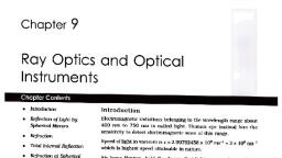
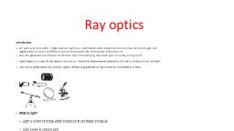
Ray optics and Optical Instruments, , Chapter 9:, RAY OPTICS AND OPTICAL INSTRUMENTS, , Optics is a branch of physics which deals about light. Optics can be, divided into three branches., 1. Geometrical Optics or Ray optics: It is a branch of optics which deals, about light on the basis of ray nature., 2. Physical optics or Wave optics: It is a branch of optics which deals about, light on the basis of wave nature., 3. Quantum Optics: It is a branch of optics which deals about light on the, basis of particle nature., Light: The electro-magnetic radiation of wavelength about 400nm to 750nm is, called light., Light produces the sensation of vision when it falls on retina of our eye., So we can see the world around us., Speed of light: Light travels with enormous speed. Speed of light in vacuum is, C=2.9979108ms-1, it is taken as, C=3108ms-1, Rectilinear propagation of light: In the homogeneous medium, the light, travels in a straight line. This is called rectilinear propagation of light., Ray of light: The path along which the light travels is called ray of light., , , It is represented as, Ray of light, Beam of light: A bundle of rays of light is called beam of light., , Types of beam of light:, 1) Parallel beam, , 2) Converging beam, , 3) Diverging beam
Page 2 :
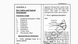
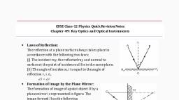
Ray optics and Optical Instruments, , What is reflection of light?, The phenomenon in which light travelling in one medium incident on the, surface of another returns to first medium is called reflection of light., Ray diagram to show reflection of light:, AO=Incident ray, OB=reflected, ray,, O=point of incidence, MN=Normal, to ‘O’, AOM ==angle of incidence (angle, between normal and incident ray), MOB ==angle of reflection (angle, between normal and reflected ray), Laws of reflection: There are two laws., I Law of reflection: The incident ray, reflected ray and normal to the reflecting, surface at the point of incidence lie in the same plane., II Law of reflection: The angle of reflection is equal to angle of incidence., i.e. angle of reflection = angle of incidence, Mirror: Mirror is a device which reflects the light., Types of mirror:, 1) Plane mirror: Reflecting surface is plane in plane mirror, 2) Spherical mirrors: A spherical mirror is one whose surface forms part of, sphere., a) Concave mirror, : In concave mirror inner part is reflecting surface., b) Convex mirror: In concave mirror outer part is reflecting surface.
Page 3 :
Ray optics and Optical Instruments, , Pole(P): It is the geometrical midpoint of spherical, mirror., Centre of curvature (C): It is centre of sphere of, which the mirror is a part., Radius of curvature (R): It is the distance between pole and centre of, curvature., i.e. R=PC=radius of curvature, Principal axis: It is straight line joining the pole and centre of curvature., Sign convention for spherical mirrors and lenses (Cartesian rule):, According to Cartesian sign, convention, 1. All distances are measured from the, pole of the mirror (or, from the, optical centre of lens)., 2. The distances measured along the, direction of incident ray are taken, as positive., 3. The distances measured opposite to the direction of incident ray are taken, as negative., 4. The heights measured upwards with respect to principal axis are taken, positive., 5. The heights measured downwards w.r.t. principal axis are taken as, negative., Principal focus of spherical mirror:, , When a parallel beam of light incident on a spherical mirror, then, reflected beam converges at a point or appear to diverges from a point on the, principal axis. That point is called principal focus.
Page 4 :
Ray optics and Optical Instruments, , In case of concave mirror, the principal focus is converging point (real, point)., In case of convex mirror, the principal focus is diverging point (Virtual, point)., Note: 1) Paraxial rays: The rays which are parallel and close to the principal, axis are called paraxial rays., 2) Marginal rays: The rays which are parallel and far away from the principal, axis are called marginal rays., 3) Focal plane: It is a plane passing through principal focus but, perpendicular to the principal axis., Focal length of spherical mirror:, The distance between pole and principal focus is called focal length., Derive the relation between focal length and radius of curvature of, spherical mirror:, The geometry of reflection of an incident, ray is shown in figure., Let, C=centre of curvature, P=Pole,, F=Principal focus, R=radius of curvature,, f=focal length,, MD=Perpendicular from M on the principal, axis., But, R=PC and f=PF, , MCD and MFD 2, From right angled triangle MDC, , tan , , MD, DC, , For small , tan=, , , , , MD, -------------(1), DC, , From right angled triangle MDF, , tan 2 , , MD, DF, , 2 , , From equation (1) and (2), , 2, , MD MD, , ,, DC, DF, , MD, ---------------(2), DF
Page 5 :
Ray optics and Optical Instruments, , , , DF , , DC, 2, , For small , D is very close to P, i.e. DP, DF=PF= -f,, , , f, , R, 2, , or, , DC=PC= -R, , R=2f, , Note:, 1. The rays from object actually meet at a point after reflection or refraction., That point is called image of the object., 2. The image is real if the rays actually converge to the point. Real image is, always inverted., 3. The image is virtual, if the ray do not actually meet but appear to diverge, from the point. Virtual image is always erect., Note4: Ray diagram for image formation by a spherical mirror:, To obtain image of the point object, it is convenient to choose any two of, the following rays., a) The ray from the object which is parallel to principal axis passes through, focus after reflection., b) When a ray of light is passed through the centre of curvature the reflected, ray retraces its path., c) If the incident ray is passing through the focus the reflected ray is parallel to, principal axis., , d) The ray incident at any angle at the pole, the reflected ray follows the laws of, reflection., Note: Focal length and radius of curvature for plane mirror are .
Page 6 :
Ray optics and Optical Instruments, , Drive the mirror equation:, The geometry of reflections of incident, rays is as shown in figure., Let, MPN= spherical mirror, AB=object,, A|B|=real image,, PF=f=focal length,, PC=R=radius of curvature, PB=u=object distance,, PB|=v=image distance, The two right angled triangles A|B|F and, MPF are similar., , , A|B| B|F, , PM PF, , But, , PM=AB, , , , A|B| FB|, , ------------- (1), AB PF, , Two right angled triangles A|B|P and ABP are similar, , , A|B| PB|, , ------------- (2), AB PB, , Comparing equations (1) and (2), , FB| PB|, , but FB| PB| PF , PF PB, PB| PF PB|, , -------------- (3), PF, PB, Applying Cartesian sign convention,, PB|=v, PB= u and PF= f, (-ve sign indicates that distances are taken opposite to the incident ray, direction), equation (3) becomes, , Or, , v f v, , f, u, v f v, , f, u, vf v, , f, u, v, v, 1 , f, u, v v, 1, f u
Page 7 :
Ray optics and Optical Instruments, , Dividing by ‘v’, , , 1 1 1, , u v f, , This is called mirror equation., , Linear magnification (m): The ratio of the height of the image to the height of, the object is called linear magnification., , h|, i.e. m , h, Where, m=linear magnification, h|=height of image, h=height of object, Magnification produced by a mirror:, In figure, triangles A|B|P and ABP are similar, , , , A|B| PB|, , AB PB, h|, v, , h, u, v, m, u, , Where, v=image distance, u=object distance, , This is the expression for linear magnification., Note:, f v, f, , f, f u, 2. If m is positive then image formed is virtual and erect., 3. If m is negative then image formed is real, inverted., , 1. m , , 4. If m 1 , then size of image= size of object., 5. Image formed is enlarged when |m|>1., 6. Image formed is diminished when |m|<1.
Page 8 :
Ray optics and Optical Instruments, , Refraction of light, Optical Medium: The medium which allows the light to pass through it is, called optical medium., Ex: Vacuum, Air, Glass, Pure water etc., Interface:, , The surface which separates two media is called interface., Refraction of light: When a ray of light incident obliquely at the interface of, two optical media, its direction of propagation changes at the interface. This, phenomenon is called refraction., Ray diagram to show refraction:, , XY = Refracting surface(Interface),, OB = Refracted ray,, MN = Normal at ‘o’,, r = Angle of Refraction,, , AO = Incident ray,, O = Point of Incidence,, i = Angle of Incidence, d = Angle of Deviation, , Laws of refraction:, First law: The incident ray, refracted ray and normal to the interface at the, point of incidence lie in the same plane., Second law (Snell’s Law): It states that, “The ratio of sine of angle of incidence, to the sine of angle of refraction is constant for a pair of media”., sin i, i.e., = Constant, Where, i = Angle of incidence, r=Angle of refraction, sin r, sin i, Relative refractive index: From Snell’s law,, =Constant, sin r, This constant is called relative refractive index., sin i, i.e. Relative refractive index =, sin r
Page 9 :
Ray optics and Optical Instruments, , It is defined as “The ratio of sine of angle of incidence to the sine of angle of, refraction”., sin i, It can be represented as, 1n2. It is read as n-two-one. i.e., n21=, sin r, , n 21 can also be writtten as 1n 2 , Note: The basic cause of refraction is that the speed of light changes as it goes, from one medium to another, 1. 1n2 means R.I. of second medium with respect to first medium., e.g.: wng=R.I. of glass w.r.t. water., 2. Refractive index measures the bending of light and it measures the velocity, of light in the medium., 3. Normal incidence:, Medium-1, , i=00, X, Y, 0, Medium-2 r=0, When a ray of light incident along the normal, then it is called normal, incidence. In the normal incidence, the light enters the second medium without, bending for normal incidence, i=00 and r=00., 1. Limitation of Snell’s law:, sin i, From Snell’s law n21=, sin r, For normal incidence, i=0o and r=0o, , sin 00 0, , n21=, sin 00 0, , it is Indeterminent form., , i.e. Snell’s law does not hold good for normal incidence or for 00 angle, of incidence., Denser medium: The optical medium which has high R.I. w.r.t. another, medium is called denser medium., Rarer medium: The optical medium which has low R.I. w.r.t. another medium, is called rarer medium., Ex: For air and water media, air is rarer medium and water is denser medium., For water and glass media, water is rarer medium and glass is denser, medium.
Page 10 :
Ray optics and Optical Instruments, , Note:, 1. The velocity of light in rarer medium is greater than that in denser medium, 2. When a ray of light travels from rarer to denser, then it bents towards the, normal., , 3. When a ray of light travels from denser to rarer, then it bents away from the, normal, , 4. Relative RI n 21 , , n 2 v1 1, , , n1 v2 2, , 5. Absolute RI n , , c, , , v m, , 6. RI of a medium has no unit and no dimension. It is just a number., 7. Optical density of a medium determines the ability of the medium to refract, light and it is directly proportional to RI of the medium., 8. Optical density and mass density are two different terms for ex, optical, density of turpentine oil is more than that of water, where as mass density, of turpentine oil is less than that of water., Relation between n21 and n12:, RI of medium 2 w.r.t medium 1 is related to RI of the medium 1 w.r.t, medium 2 as, , n 21 , , 1, n12, , Expression for n32:, RI of medium 3 w.r.t. medium 2 can be expressed as, , n 32 , Note: n gw n ga n aw, , n 31, n 21, , or, , n 32 n 31 n12
Page 11 :
Ray optics and Optical Instruments, , Consequence of refraction: Lateral shift, and normal shift are due to refraction., Lateral shift:, In rectangular slab, the refraction takes, place at two interfaces as shown in figure., In this case., i.e. angle of emergence=angle of, incidence, Emergent ray is parallel to incident ray. The incident ray suffers lateral, shift., The perpendicular distance between emergent ray and incident ray, direction is called lateral shift., , Note:, 1. During lateral shift, net deviation=0, t, sin(i r ), cos r, Where, t = thickness of slab, i = angle of incidence, r = angle of refraction, 3. If r=00 and i=900 then cosr=1, sin(i-r)=1,, Ls=t, i.e., Lateral shift is maximum and equal to thickness of slab., 4. If i=00, r=00 then cosr=1, sin(i-r)=0, Ls=0 and lateral shift is minimum., , 2. Expression for lateral shift is, LS , , Normal shift: It is the apparent shift in the position of an object kept in one, medium when viewed along, normal through another, medium., Ex: The bottom of the tank filled, with water appears to be raised., It can be shown that,, real depth, R.I. of medium, r.d, a. d=, ,, n, n=R.I. of denser medium., , Apparent depth=, , 1, Note: Expression for normal shift is, N s r.d 1 , n
Page 12 :
Ray optics and Optical Instruments, , Atmospheric refraction:, Sun is visible little before sunrise and little after, sunset. Explain why?, The sun is visible little before the actual, sunrise and little after the sunset. This is due to, atmospheric refraction., The RI of air with respect to vacuum is 1.0029., Due to this, the apparent shift in the direction of the sun is by about half a, degree and the corresponding time difference between actual sunset and, apparent sunset is about 2 minutes., The apparent flattening (Oval shape) of the sun at sunset and sunrise is, also due to the same phenomenon., Critical Angle: It is the angle of incidence in denser medium at which the, angle of refraction becomes 900, Or, It is the angle of incidence in denser medium at which the refracted ray, grazes the interface., , i.e. If i=ic, then r=900. At critical angle the refracted ray grazes the, interface., Relation between n and ic:, 1, 1, n, or sin i c , sin i c, n, n|, n, Where, n’=R.I. of rarer, , Note: If rarer medium is other than air. sin i c , , Total internal reflection (T.I.R):
Page 13 :
Ray optics and Optical Instruments, , When a ray of light travels from denser to rarer medium and if an angle, of incidence is greater than critical angle, then the light is totally reflected back, into denser medium. This phenomenon is called TIR., Conditions for TIR:, 1. The light ray should travel from denser to rarer medium., 2. Angle of incidence should be greater than critical angle., Explain Total internal reflection:, When a ray of light travels from denser to rarer medium, it bends away, from the normal. On increasing the angle of incidence, angle of refraction also, increases., When angle of incidence is equal to critical angle the refracted ray just, grazes the interface., When the angle of incidence becomes greater than the critical angle, then, the ray gets reflected back into the same medium, this phenomenon is called, TIR., Experimental demonstration of TIR:, , Take a laser pointer and shine its beam through the turbid water., When we shine the beam from below the beaker, we observe that the beam, undergoes partial reflection and partial refraction at the free surface of, water in the beaker. (fig a)., When we direct the laser beam from one side of the beaker and adjust its, direction so that refraction above the water surface is totally absent, we, observe that the beam is totally reflected back to water from its upper, surface. This is TIR (fig b), Note: If we repeat this experiment by taking turbid water in a long, test tube and shine the laser beam from the top at a suitable angle,, the beam is totally internally reflected repeatedly from the walls of, the test tube as shown in figure.
Page 14 :
Ray optics and Optical Instruments, , CRITICAL ANGLE OF SOME TRANSPARENT MEDIA, Substance, Refractive, Critical, medium, index, angle, Water, 1.33, 48.75°, Crown glass, 1.52, 41.14°, Dense flint glass, 1.62, 37.31°, Diamond, 2.42, 24.41°, Application of TIR, 1) Diamond: Brilliance of diamond is mainly due to the TIR of light., The RI of diamond is 2.42, hence if critical angle is very small (24.40). If it, is cut suitably, so that the light falls at an angle greater than 24.40. Therefore it, suffers multiple total internal reflections. Thus diamond sparkle brilliantly., 2) Porro-prism:(total reflection prism), A right angled isosceles prism called porro-prism, works on the principle of TIR of light. It can be used to bend, the light through 900 and 1800 and also to invert the image, of an object without changing its size., The incident beam is turned by an angle 900. This arrangement is used, in periscope., , Note:, 1) The incident beam is turned though 1800, this arrangement, is used in binoculars., , 2) This arrangement, inverted image., , is, , used, , to, , make
Page 15 :
Ray optics and Optical Instruments, , 3) Mirage:, , Mirage is an optical illusion caused due to TIR and refraction., On a hot day density of air layer increases with height. A day of light, travelling from top of a tree downwards, more from denser medium to rarer, medium. When the angle of incidence greater than critical angle, the ray, undergoes TIR., A distant observer sees the object as well as the image floating on the, ground, he gets the impression of water pool near the object. This optical, illusion is called mirage., It is observed in deserts and in highways during hot days., , 4) Optical fibres:, It is a transparent fibre which transmits light introduced at one end to, the opposite end through repeated TIR., It works on the principle of TIR., It is made of high quality glass or quartz of high RI called core and, coated with glass material of low RI called cladding., , A ray of light entering one end of the fibre at an angle greater than, critical angle, undergoes multiple TIR and emerges through the other end, without loss of energy., Note: The sleeve containing a bundle (104) of optical fibres is called as light, pipe.
Page 16 :
Ray optics and Optical Instruments, , Uses of optical fibres: optical fibres are used, To transmit light without any loss in its intensity., As light pipe to examine internal organs like stomach, esophagus, intestine., Etc., As decorative lamps., To transmit and receive electrical signals, which are converted into light by, transducers., In the field of communication.
Page 17 :
Ray optics and Optical Instruments, , Refraction at spherical surface, Derive the relation between u, v, n and R For spherical surface:, , , , , , , , The geometry of refraction of light at spherical surface is as shown., Let, O=real object, I=real image of ‘O’, C=centre of curvature, i=angle of incidence., r=angle of refraction,, ON = incident ray, NI = Refracted ray, NC = normal, n1=R.I. of medium (1), n2=R.I. of medium (2),, NM=perpendicular to principal axis., MN, tan , From right angled triangle NMO,, MO, MN, , For small angle,, tan , if , MO, MN, tan , From right angled triangle NMC, MC, MN, , , MC, MN, From right angled triangle NMI, tan , MI, MN, , , MI, From triangle NOC,, i , (exterior angle = sum of interior opposite angles), , From triangle NCI,, , i, , MN MN, , ------------------ (1), MO MC, , r, , , , is exterior angle
Page 18 :
Ray optics and Optical Instruments, , , , ˆ NIM, ˆ , NIC, , r , , MN MN, ----------------- (2), , MC MI, n1 sin i n 2 sin r, r, , From Snell’s law, , For small angles sini=i and sinr=r, n1 i n 2 r, , From equation (1) and (2), MN MN , MN MN , n1 , , n2 , , , , MO MC , MC MI , n1, n, n, n, , 2 2 1 ------------------- (3), MO MI MC MC, Applying Cartesian sign convention, MO=u= object distance, MI=+v=image distance, MC=+R=radius of curvature, , , , Equation (3) becomes, n1 n 2 n 2 n1, , , , u v, R R, n 2 n1 n 2 n 1, , v u, R, This is the relation between u, v, n and R., Note:, 1. If the object lies in the rarer medium, then, , n 2 n1 n 2 n1, , is valid, v u, R, , irrespective of the type of the spherical refracting surface., 2. If object lies in the denser medium, then, , n1 n 2 n1 n 2, , , is valid, v u, R, , irrespective of the type of the spherical refracting surface., 3. The factor, , n 2 n1, n n2, or 1, measures the power of a refracting surface., R, R, , Lens:, Lens is an optical medium bound by two surfaces of which at least one is, spherical., There are two types,, 1. Convex lens: A lens which is thinner at the edges and thicker at the middle, is called convex lens.
Page 19 :
Ray optics and Optical Instruments, , 2. Concave lens: A lens which is thinner at the middle and thicker at the, edges is called concave lens., Types of convex lens, , R2=, , Biconvex lens, Equiconvex lens, Plano-convex lens, (R1 and R2 may different), (R1 and R2 are equal), Types of concave lens, R2=, , Biconcave (R1R2), , Equiconcave (R1=R2), , Plano concave, , Optic centre of lens: It is a point in a lens on the principal axis through which, a ray of light passes without deviation., , O, O, ‘O’ is the optic centre, Principal focus(F):, O, , F, , F, , O, , Convex lens, Concave lens, It is a point on the principal axis where the parallel the beam of light, converge or appear to diverge after refraction., In case of convex lens the light rays are converged at F. In case of, concave lens the light rays appear to be diverged from F., Focal length: It is the distance between optic centre and principal focus of a, lens. SI unit is ‘m’.
Page 20 :
Ray optics and Optical Instruments, , Derive the lens makers formula:, , The geometry of image formation by a double convex lens is as shown in figure., We have,, , n 2 n1 n 2 n1, , v u, R, , Where, n1=RI of object space (RI of surrounding), n2=RI of image space (RI of, lens), u=object distance, v=image distance, R=radius of curvature., The light ray undergoes two refractions at ABC and ADC surfaces., Case1: Refraction at surface ABC, Let O=real object, I1=real image of, ‘O’, C1=centre of curvature,, u = –BO, v = +BI1, n2n2, n1n1,, R= BC1=+R1=radius of curvature, of ABC, equation (1) becomes, n2, n, n n1, 1 2, BI1 BO, R1, n2, n, n n1, 1 2, ----------------(2), BI1 BO, R1, , Case2: Refraction at surface ADC, In this case,, I1 acts a virtual object for ADC, surface., I= Real image of I1, u = +DI1=+BI1(for thin lens B, and D are very close to each other), v =+DI, R = DC2 = – R2=radius of, curvature of ADC, n2n1 and n1n2, Equation (1) becomes
Page 21 :
Ray optics and Optical Instruments, , n1 n 2, n n1, , 2, ------------- (3), DI BI1, R2, , Adding equation (2) and (3), , n2, n, n, n, n n n n, 1 1 2 2 1 2 1., BI1 BO DI BI1, R1, R2, 1, n1 n1, 1 , , n 2 n1 , , --------- (4), BO DI, R1 R 2 , If the object is at infinity, Then BO=, DI=f=focal length of lens, , equation (4) becomes, , 1, n1, 1 , n 2 n1 , ---------- (5), f, R1 R 2 , 1 n 2 n1 1, 1 , , , , f n1 R 1 R 2 , 1 n2 1, 1 , 1 , , f n1 R 1 R 2 , 1, 1, 1 , n 21 1 , , f, R1 R 2 , , , n2 , Q n 21 , n1 , , , This is called lens maker’s formula., , Note-1: If the surrounding is air, n1=na=1, then, , 1, 1, 1 , n 1 , , f, R1 R 2 , , Where, n=RI of lens., Note-2: If the thickness of lens is negligible compared to its radii of curvature, then the lens is called thin lensx., Note3: The position of an object on the principal axis of the lens for which the, image is formed at is called first principal focus of the lens., The position of an image on the principal axis of the lens whose object is, lying at is called second principal focus of the lens., Note-4: A ray emanating from the object parallel to the principal axis of the, lens after refraction passes through the second principal focus. F1 (in a convex, lens) or appear to diverge (in a concave lens) from it.
Page 22 :
Ray optics and Optical Instruments, , A ray of light, passing through the optical centre of the lens, emerges, without any deviation after refraction., A ray of light passing through the first principal focus (for a convex lens), or appearing to meet at it (for a concave lens) emerges parallel to the principal, axis after refraction., Note-5: The thin lens formula is given by, 1 1 1, ,, v u f, Where, v=image distance, u=object distance, f=focal length., Linear magnification of lens (m):, It is defined as the ratio of height of image to the height of object., i.e. m , and also, , h|, h, , m, , m, , v, u, , Where h|=height of image, h=height of object, Where, v=image distance, u=object distance, , h| v, , h, u, , Sign convension for linear magnification:, 1. ‘m’ is positive for erect and virtual image formed by convex and concave, lens., 2. m is negative for inverted and real image., Power of lens: It is defined as the tangent of the angle by which it converges or, diverges a beam of light falling at unit distant from the optical centre., 1, Power of a lens is given by P , f, Where, f=focal length in metre., S.I. unit of power is dioptre (D).
Page 23 :
Ray optics and Optical Instruments, , Define one dioptre:, 1, We have, P , If,, f=1m,, f, Then, P=1D, i.e. The power of lens is said to be one dioptre if focal length is 1 metre., Show that power of a lens is reciprocal of its focal length:, From the diagram, tan , If,, , h, ,, f, , h=1m, , tan , , 1, f, , For small angles, tan, , 1, ,, f, since, , p, , p, , 1, f, , Note: 1) Power is also defined as the reciprocal of focal length., 2) Power is positive for convex lens and negative for concave lens., Derive the expression for equivalent focal length of two thin lens in, contact:, , Consider two thin lens A and B in contact., Let, f1=focal length of A, f2=focal length of B, O=real object, The thin lens formula is, 1 1 1, ---------- (1), v u f, Where, v=image distance, u=object distance, f=focal length., The geometry of image formation is as shown.
Page 24 :
Ray optics and Optical Instruments, , Case1: Image formation by lens A., Let, O=real object, I1=real image, v=v1, u=u and f=f1, equation (1) becomes, 1 1 1, , ----------- (2), v1 u f1, Case2: Image formation by lens B. Here, I1 acts as virtual object and I is real, image., v=v, u=v1, and f=f2, equation (1) becomes,, 1 1 1, , ----------- (3), v v1 f 2, Adding equation (2) and (3), 1 1 1 1 1 1, , v1 u v v1 f1 f 2, 1 1 1 1, , --------------- (4), v u f1 f 2, , 1 1 1, , f=equivalent focal length, v u f, Equation (4) becomes, 1 1 1, , f f1 f 2, , But, , This is the expression for equivalent focal length of two thin lenses in, contact. If ‘n’ number of thin lens are in contact, then, 1 1 1 1, 1, .... , f f1 f 2 f 3, fn, In terms of power, WKT P , , 1, ,, f, , , , 1, 1, P, P2 , ..........., f1, f2, , Thus, P P1 P2 .......... Pn, Where, P is the net power of the lens combination., Note:, 1. Total magnification of combination of two lens is m=m1m2, Where, m1=magnification of first lens, m2=magnification of second lens, for ‘n’ number of lenses,, m=m1m2m3….mn., Thus the combination of lenses increases the magnification of the final, image, 2. System of combination of lenses is commonly used in designing lenses for, cameras, microscopes, telescopes and other optical instruments.
Page 25 :
Ray optics and Optical Instruments, , Derive the expression for refractive index of the material of the prism:, Consider a prism ABC in air medium let n be the R.I. of prism and A be, the angle of prism. The light ray undergoes refraction through a prism as, shown in ray diagram., For AB surface, Let PQ=incident ray, QR=refracted ray, i=angle of incidence, r1=angle of refraction, d1=angle of deviation, d1=i-r1, For AC surface, Let QR=incident ray, RS=emergent ray,, r2=angle of incidence, e=angle of emergence, d2=angle of deviation, d2=e-r2, Total deviation, d=d1+d2=(i-r1)+(e-r2), d=i-r1+e-r2, d=i+e-r1-r2, d=i+e-(r1+r2) ---------- (1), From quadrilateral AQNR, A+ QNR =1800---------- (2), From triangle QNR, r1+r2+ QNR =1800---------- (3), From equations (2) and (3), A+ QNR =r1+r2+ QNR, A =r1+r2 ---------- (4), Substituting (4) in (1), d=i+e-A -------------- (5), As angle of incidence increases, angle of deviation varies as shown in, graph., At minimum deviation position of prism, i=e, r1=r2=r and d=D=angle of minimum deviation., equation (5) becomes, D=i+i-A, D=2i-A, A+D=2i
Page 26 :
Ray optics and Optical Instruments, , AD, 2, Equation 4 becomes, A=r+r,, A=2r, A, r, 2, sin i, From Snell’s law, n , sin r, i, , AD, sin, , 2 , , n , A, sin , 2, This is called prism formula., Angle of minimum deviation:, It is the minimum value of the angle of deviation for a ray passing, through a prism., Thin prism: The prism whose angle is about 80 is called thin prism or small, angled prism., Deviation produced by a thin prism:, , W.K.T., , AD, sin , , 2 , , n, A, sin , 2, For a thin prism A and D are very small, , , , AD, n 2, A, 2, , D n 1 A .
Page 27 :
Ray optics and Optical Instruments, , Dispersion by a prism:, R, O, Y, White light, R G, V B, I, V, Spectrum, When white light is passed through a prism it splits up into its, constituents colours. This is called dispersion., Spectrum: The band of colours obtained by a prism is called spectrum., There are two types, I. Pure spectrum: A spectrum in which colours are not overlapped is called, pure spectrum., Ex: Spectrum obtained by a prism., II. Impure spectrum: A spectrum in which colours are overlapped is called, impure spectrum, Ex: Rainbow., Newton’s classic experiment on dispersion: (A beam of light passing, through a glass slab does not undergo dispersion. Explain?), , Arrange two prisms as shown in figure (Equivalent to glass slab), White light is split into its component colours by the first prism. Each, color is due to some wavelength of light. RI of glass is different for different, wavelengths. Red component of light bends the least, where, as violet, component bends the most in glass. When an inverted prims is placed near the, first prism, it reverses the action of the first prism. The output available from, the second prism again white light.
Page 28 :
Ray optics and Optical Instruments, , Note:, 1. Deviation of violet is greater than that of red. dV>dR., 2. nV>nR, Where, nV=R.I. of prism for violet., nR=R.I. of prism for red, 3. vR>vV, where, vR= velocity of red in prism, vV=velocity of violet in prism, 4. R>V, Where, R=Wavelength of red, V=Wavelength of violet., 5. The spectrum due to sunlight is called solar spectrum., 6. Red, blue and green are called primary colours. Other colours can be, obtained by mixing primary colours., 7. Vacuum is a non dispersive medium, because all colours travel with the, same speed., The Rainbow:, It is the combined effect of, refraction, total internal reflection and, dispersion of light by water droplets of, rain., Primary rainbow: It is a result of three, steps process, that is refraction, total, internal reflection and refraction., In primary rainbow, red colour, present on the top and violet on the, bottom., , Secondary rainbow: It is a result of, four step process, that is refraction,, two total internal reflections and, refraction., In secondary rainbow, the, violet colour is present on top and, red on the bottom.
Page 29 :
Ray optics and Optical Instruments, , Scattering of light, When a beam of light is passed through a material medium, the, molecules absorb light, get excited and re-emit the light in all possible, directions., The phenomenon of absorption and re-emission of light in all, possible direction by the molecules of the medium is called scattering of, light., The scattering of light depends upon the size of the scatterers in the, atmosphere., The scattered light is partially plane polarized., Rayleigh’s scattering law:, It states that, “the intensity of scattered light is inversely proportional to, fourth power of the wavelength of incident light”., 1, I 4 Where, I= intensity of scattered light,, = wavelength of, , incident light., Note:, Types of scattering:, Coherent scattering: The scattering in which the frequency of scattered light, is same as that of incident light is called coherent scattering. It is also called, elastic scattering or Rayleigh’s scattering. Ex: atmospheric scattering, The coherent scattering takes place when the size of the scatterer is, equal to or less than wavelength of incident light., Incoherent scattering: The scattering in which the scattered light has lower, and higher frequencies in addition to incident light frequency is called, incoherent scattering. It is also called inelastic scattering or Stokes scattering., Ex: Raman effect, Compton Effect., Incoherent scattering takes places when size of the scatterer is greater, than wavelength of incident light., The blue colour of sky and sea:, The blue colour of sky and sea are due to coherent scattering by, atmospheric molecules., 1, From Rayleigh’s scattering law., I 4, , When sunlight passes through the atmosphere, the violet and blue, colours are scattered more (due to less wavelength), but orange and red colours, are scattered less (due to more wavelength). So molecules present in the, atmosphere emit the light of violet and blue colours with maximum intensity., Our eyes are sensitive to blue colour. Thus the sky and sea appears blue, colour.
Page 30 :
Ray optics and Optical Instruments, , Reddish appearance of sun at sunrise and sunset:, Sunlight travels through a, longer distance in the atmosphere at, sunrise and sunset. Most of blue and, other, shorter, wavelengths, are, removed by scattering. The Least, scattered light (red to orange), reaching our eyes. Therefore sun, looks reddish., Optical instruments: Optical devices and instruments have been designed, utilising reflecting and refracting properties of mirrors, lenses and prisms,, periscope, kaleidoscope, binoculars, telescopes, microscopes are some, examples of optical instruments., The Eye: The eye is an optical device, which acts as a natural camera. Light, enters the eye through a curved front, surface, cornea. It passes through the, pupil which is the central hole in the iris., The size of the pupil can change under, the control of muscles. The light is further, focused by the eye lens on the retina., The retina is a film of nerve fibres, covering the curved back surface of the eye. The retina contains rods and, cones which sense light intensity and color respectively and transmit electric, signals via the optic nerve to the brain, which finally processes this, information., The shape and focal length of eye lens can be modified by the ciliary, muscles., Note, 1. The distance between retina and eye lens should be fixed i.e., V=2.5cm, 2. The average RI of crystalline lens is 1.43, 3. The average RI of aqueous humour and vitreous humour is 1.336
Page 31 :
Ray optics and Optical Instruments, , Accommadation: The modification of the focal length of the eye by the ciliary, muscles to see the objects at all distances is called accommadation., Least distance of distinct vision (D): (Near point), The closest distance for which the lens can focus light on the retina is, called the least distance of distinct vision., D=25cm for normal vision (normal eye), Note:, 1. D=7 to 8cm in child ten years age. D200cm in a person at 60 years age, 2. Eye has a capability to interpret incoming electromagnetic waves as image, through a complex process., 3. Far Point:, It is the largest distance for which the lens of the relaxed eye can focus, light on the retina. For a person with normal vision far point is near ∞., 4. Range of Vision:The distance between the near point and far point of an eye is known as, range of vision. For a normal adult eye, the range of vision is 25cm to ∞., 5. Power of accommodation:Power of accommodation of an eye is defined as the maximum variation, in the power of the eye lens. For a normal eye the power of accommodation, is about 4D., Common Defects of Vision:, (a) Short sightedness or Myopia. (b) long sightedness or Hypermetropia, (c) Presbyopia, (d) Astigmatism, Correction of eye defects:, Nearsightedness or Myopia: If the eye lens converges light coming from, distant object at a point in front of retina. This defect is called nearsightedness, or myopia., The myopia can be corrected by using concave lens between the eye and, object., , Note: The person having shortsightedness can see near objects but far objects, are blurred.
Page 32 :
Ray optics and Optical Instruments, , Farsightedness or Hypermetropia: If the eye lens converges light coming from, near objects at a point behind the retina. This defect is called farsightedness or, hypermetropia., Hypermetropia can be corrected by using a convex lens between eye and, object., , Note:, 1. The person having farsightedness can see distant objects but near objects, are blurred., Presbyopia:, A human eye which cannot see near as well as far objects clearly is said, to be suffering from a defect known as Presbyopia., Presbyopia can be corrected by using bi-focal lens. i.e, upper surface of, the lens is diverging (concave) and it corrects myopia. Lower surface of the lens, is converging and it corrects Hypermetropia., Astigmatism:, A human eye which cannot focus on both horizontal and vertical lines, simultaneously is said to be suffering from a defect known as Astigmatism. It, can be corrected by using a cylindrical lens of desired radius of curvature., , Microscope: The optical instrument used to see very small objects which, cannot be seen by naked eye is called microscope., Simple microscope: A simple microscope is a converging lens of small focal, length., Ex: Reading lens, Expression for magnification of simple microscope when the image is at, near point:When an object is placed between optical centre and principal focus, a, virtual, erect and magnified image is obtained. The position of the object is, adjusted so that, the image obtained at near point.
Page 33 :
Ray optics and Optical Instruments, , Linear magnification,, , m, , v, u, 1 1 1, , f v u, , WKT, , 1 1 v, m v 1 , v f f , According to the sign convention. v = -D, , m 1, , D, f, , Define magnifying power (Angular magnification) of a simple microscope, and hence obtain an expression for it when the image is formed at ∞., Magnifying power is defined as the ratio of the angle formed by the, image(at ∞) to the angle formed by the object at the eye, when situated at least, distance of distinct vision., Magnifying Power= M , , , ., , , Where, α= angle formed by the, object at the eye, when it is at D., β= angle formed by the, image at the eye., Since α and β are small, tan = , and tan β= β., , m , , tan , tan , , tan , , ho, h, , 1 , tan i, D, v, , tan , , ho v, h, o, v u, u, , , h, v, Q m i , ho u , , , Angle formed by the object, when it is at u = -f., , ho, , 2, f, D, m , f, , tan , , from (1) and (2)
Page 34 :
Ray optics and Optical Instruments, , Compound microscope:, Compound microscope, has two lenses. The lens, nearest to the object is called, objective. The lens nearest to, the eye is called eye piece., Objective is a convex, lens of short focal length and, small aperture. Eyepiece is, also a convex lens but of, large aperture and large focal, length. When the object AB is, placed at a distance greater, than the focal length of the objective, a real inverted and magnified image AB, is formed. The position of the eye piece is adjusted such that AB lies within, its principal focus. Hence AB serves as object to form a final image AB, which is virtual, erect enlarged image., Magnification of objective , m0 , , hi L, , h 0 f0, , Eye piece behave like a simple microscope me 1 , , D, fe, , Magnifying power of a compound microscope, m mo me, , L D , m m o m e 1 , f o f e , When the final image is at , then m e , , D, fe, , Magnifying power of a compound microscope is, , L D, m mome , f0 fe , Where f 0 = focal length of the objective, f e = focal length of the eye piece, L= length of the tube, D= least distance of distinct vision.
Page 35 :
Ray optics and Optical Instruments, , Telescope:The optical instrument used to, see, distant, objects, is, called, telescope. It has an objective and an, eyepiece. Objective is a convex lens, of large aperture and long focal, length. The eye piece is also a convex, lens but of small aperture and short, focal length. The rays from a distant, object converges to form an image, AB . The eye piece is adjusted such that, focus. Thus the final image is obtained at ∞., , AB lies exactly at its principal, , Magnifying power of telescope:, It is defined as ratio of angle subtended by final image at eye to the angle, subtended by the object at the eye., Magnifying power, M , , fo, , fe, , length of the telescope, L f 0 f e, Where f 0 = focal length of objective, , f e = focal length of eye piece, Reflecting Telescope (Cassegrain Telescope):Telescope with mirror objectives is called reflecting telescope., Casse grain telescope consist of concave mirror of 5m in diameter with a, narrow hole at its centre. Parallel rays from a distant star incident on the, mirror, tends to converge at its principal focus. But before converging, they get, reflected by the secondary convex mirror on the eyepiece. The final image is, seen through the telescope., Thus the magnifying power of reflecting telescope., , R, f0 2, R, m , , f e f e 2f e, f e = focal length of eye piece, R= Radius of the curvature of the, convex mirror.
Page 36 :
Ray optics and Optical Instruments, , Answer the following questions:, 1. Define the terms (a) ray of light & (b) beam of light, 2. Which are the common defects of human eye?, 3. What is accommodation of eye?, 4. Define linear magnification., 5. Write the expression for the magnification in terms of object and image, distance, 6. What is refraction of light?, 7. Write the formula for refractive index for normal refraction., 8. Define critical angle., 9. Write the relation between refractive index and critical angle of a material, 10. What is total internal reflection?, 11. On what principle optical fibre does works?, 12. What is a lens?, 13. Write the expression for power of a lens, 14. What is dispersion of light?, 15. State Rayleigh’s law of scattering., 16. Mention the expression for linear magnification of a simple microscope, 17. Mention the expression for angular magnification of a simple microscope, 18. State laws of reflection, 19. Write the sign conventions used for measuring distances in case of, spherical surfaces, 20. State laws of refraction., 21. Draw diagram representing lateral shift (lateral displacement) of a ray, passing through a parallel sided glass slab., 22. Draw diagram representing apparent depth for (a) normal and (b) oblique, viewing, 23. Mention a few illustrations that occur in nature due to refraction of light., 24. What happens to the direction of the incident ray when it travels from (a), optically denser medium to rarer medium & (b) optically rarer medium to, denser medium?, 25. Write the conditions to have total internal reflection, 26. Mention a few illustrations of total internal reflection, 27. Write the expression for the power of a combination of number of thin, lenses, 28. Define power of a lens. Write its S.I unit., 29. Why sky is blue in color?, 30. Why sun is red at rise and set?, 31. What is least distance of distinct vision? Write its value., 32. What is myopia? Why it occurs? How to correct it?, 33. What is hypermetropia? Why it occurs? How to correct it?
Page 37 :
Ray optics and Optical Instruments, , 34. Draw ray diagram of a simple microscope, 35. Draw ray diagram showing the image formation in a compound, microscope and label the parts., 36. Mention the expression for magnification of a compound microscope, 37. Draw the ray diagram of a refracting telescope and label the parts., 38. Draw schematic diagram of a reflecting telescope, 39. Derive the relation between focal length and radius of curvature of a, spherical mirror, 40. Derive mirror equation., 41. Derive the relation between object and image distance in terms of, refractive index of the medium and the radius of curvature of the spherical, surface OR derive the relation between n, u, v, & R., 42. Derive lens maker’s formula, 43. Derive the expression for effective focal length of two thin lenses in contact, 44. Arrive at the expression for refractive index of material of prism in terms of, angle of the prism and angle of minimum deviation., , ~*~*~*~*~*~