Notes of Class 12th, Physics 6 Electromagnetic induction.pdf - Study Material
Page 1 :
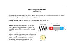
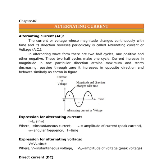
Chapter-6:, , ELECTRO-MAGNETIC INDUCTION, Introduction:, Electricity and magnetism were considered separate and unrelated, phenomena for a long time. But in nineteenth century the scientists oriested, and Ampere established the fact that electricity and magnetism are, interrelated. They found that moving electric charge or current produces the, magnetic field. Michael Faraday and Joseph Henry have demonstrated the, converse effect. That is variable magnetic fields produce the current., The phenomena in which electric current is generated by varying, magnetic fields is called electromagnetic induction., Electromagnetic induction was discovered by Faraday and Joseph Henry., Note: Is not merely of theoretical or academic interest but also of practical, utility. Imagine a world where there is no electricity - no electric lights, no, trains, no telephones and no personal computers. The pioneering experiments, of Faraday and Henry have led directly to the development of modern day, generators and transformers. Today’s civilisation owes its progress to a great, extent to the discovery of electromagnetic induction., THE EXPERIMENTS OF FARADAY AND HENRY, The discovery and understanding of electromagnetic induction are based on a, long series of experiments carried out by Faraday and Henry. We shall now, describe some of these experiments., Experiment 1: Coil-Magnet experiment:, The arrangement consists of a coil with a galvanometer and a bar magnet, as shown in figure., Observation: It was observed that., 1. When the bar magnet was at rest, the, galvanometer showed no deflection., 2. When the north-pole of a bar magnet is, moved towards the coil C1, the galvanometer, shows a deflection. This indicates that, electric current is induced in the coil., 3. When north-pole of a bar magnet is moved, away from the coil, the galvanometer shows, deflection in the opposite direction, which, indicates reversal of the current’s direction.
Page 2 :
4. When the south-pole of the bar magnetic is moved towards or away from the, coil, the deflections in the galvanometer are opposite to that observed with, the north-pole for similar movements., 5. When the bar magnet is held fixed and the coil C1 is moved towards or away, from the magnet, the same effects are observed., 6. The deflection is found to be larger when the magnet is pushed towards or, pulled away from the coil faster., 7. The deflection lasts as long as coil C1 is in motion., Conclusion: It shows that, ‘The relative motion between the coil and magnet, induces the electric current in the coil.’, Experiment 2: Coil-Coil experiment:, The coil C1 is connected to galvanometer and second coil C2 is connected, to battery as shown., Observation: It was observed that,, 1. As coil C2 is moved towards the coils C1 the, galvanometer shows a deflection. This indicates, that electric current is induced in coil C1., 2. When the coil C2 is moved away, the, galvanometer shows a deflection again, but in the, opposite direction., 3. The deflection lasts as long as coil C2 is in, motion., 4. When the coil C2 is held fixed and C1 is moved,, the same effects are observed., Conclusion: The relative motion between the coils that induces the electric, current., Experiment 3:, The coil C1 is connected to, galvanometer and second coil C2 is, connected to battery through a taping, key (K) as shown., Observation: It was observed that,, 1. Galvanometer shows a momentary, deflection when the tapping key k, is pressed., 2. The pointer in the galvanometer, returns to zero immediately, if the, key is held pressed continuously., 3. When the key is released,, galvanometer shows a momentary deflection again but in the opposite, direction., 4. It is also observed that the deflection increases dramatically when an iron, rod is inserted into the coils along their axis.
Page 3 :
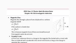
Conclusion: In this experiment, the coils have no relative motion yet changing, current on primary coil induces emf, in the secondary coil., Note: The motion of a magnet towards or away from coil C1 in experiment (1), changes the magnetic flux linked with the coil C1. The change in magnetic flux, induces an emf in the coil C1. Therefore induced emf produces the induced, current to flow in coil C1 and through galvanometer., Faraday’s law of Induction:, It states that “the magnitude of the induced emf in a circuit or coil is, equal to the time rate of change of magnetic flux through the circuit”., i.e., , induced emf= - rate of change of flux, , i.e., , e, , d B, dt, , Where, e=induced emf, dB=change in magnetic flux in dt second., Negative sign indicates the direction of emf., Note:, 1. Faradays law for a coil having ‘N’ number of turns is,, e N, , d B, ., dt, , Where, N=number of turns in the coil, If N increases e also increases, 2. We have e , , d B, dt, , But dB BA cos , , (dB=BdScos), , i.e. Magnetic flux can be changed by changing B, A or , Magnitude of e can be changed by changing B, A or , Lenz’s law: It states that “The polarity of induced emf is such that it tends to, produce a current which opposes the change in magnetic flux that produced, it”.
Page 4 :
Verification of Lenz’s law and conservation of energy (Qualitative study):, According to Faraday’s law, d, e B, dt, Negative sign indicates that induced emf and induced current oppose the, change in magnetic flux., As the north pole of a magnet moves towards the, coil, the magnetic flux through the coil increases., Hence current is induced in the coil in such a direction, that it opposes the increase in flux. This is possible, only if the current in the coil is in a anticlockwise, direction. As a result the face of coil towards the north, pole of magnet behaves as a north pole as shown in figure., Similarly, if the north pole of a magnet is moving, away from the coil, then magnetic flux through the coil, decreases. To oppose this decrease in magnetic flux,, the current in the coil is induced in clockwise, direction. As a result the face of a coil towards the, northpole of a magnet behaves as a south pole as show, in figure., In the above cases, the bar magnet experiences a repulsive force due to, induced current therefore the person has to do work in moving the magnet., The work done by the person is converted into electrical energy. Hence Lenz’s, law follows law of conservation of energy., Derive the expression for motional electromotive force:, Let us consider a rectangular conductor PQRS in which the conductor PQ is, free to move., r, Let, B = Magnetic field perpendicular to plane of PQRS,, l=length of conductor PQ,, x=distance between RS and PQ, v=constant velocity of PQ, Area of loop PQRS is, A=lx, The magnetic flux enclosed, by the loop PQRS is, B=Blx, According to Faraday’s law
Page 5 :
d B, dt, Where, e=induced emf in straight conductor PQ, d, , e Blx , dt, dx, [Q x changes with time], e Bl, dt, dx, Q, v,, e Bl v , dt, e, , e Blv, This is the expression for motional emf., , Note:, B=BAcos, =00, cos 00 = 1, A=lx, B=Blxcos00, B=Blx, -ve sign indicates, , PQ moves from right to left, (along –ve x-axis), , Note: The name motional emf is because we can produce induced emf by, moving a conductor instead of varying the magnetic field., Derive the expression for motional emf by using Lorentz force:, Let, q= any arbitrary charge in the, conductor PQ, v=velocity of conductor PQ., Therefore the charge will also be, moving with velocity ‘v’ in the magnetic, r, r, field B [ B and v are perpendicular to, each other], The Lorentz force acting on ‘q’ is, F=qvB, Therefore all the charges experience the same force and they move from P to Q., workdone = force displacement, w.k.t. Lorentz force, W=Fl, F=qE+qVBsin, Where, l=length of PQ, E=0,, W=qvBl, F=qVBsin, W, =900, sin900=1, vBl, ---------------- (1), F=qVB, q, But, , e, , W, q, , emf e , , equation (1) becomes, e=Blv, , workdone, charge
Page 6 :
A quantitative study of Lenz’s law (Energy consideration):, Let, I=induced current in the loop PQRS, e=induced emf,, r=resistance of movable arm PQ, Assume that other arms QR, RS and SP have negligible resistance., e, But I , r, But e=Blv, Bl v, , -------------- (1), I, r, Force acting on moving, conductor PQ is, F=BIlsin, but =900, sin900=1, , F=BIl, Blv , F B, l, r , , (from equation (1)), B2 l 2 v, -------------------(2), r, To push the rod PQ, the power is required, P=Fv, from equation (2), [Power=ForceVelocity], F, , B2 l 2 v 2, ------------------ (3), r, Equation (3) is the mechanical power (i.e. mechanical energy required to, push the rod), This mechanical energy is converted into electrical energy and finally, electrical energy is converted into thermal energy (Joule heat)., Joule heat is given by, PJ =I2r, (Electrical power=current resistance), P, , 2, , Blv , PJ , r, r , , (from equation (1)), , B2l 2 v 2, PJ , ---------------- (4), r, i.e. equation (3) and (4) are identical, This indicates that, mechanical energy which was needed to move the, arm PQ is converted into electrical energy and then thermal energy, i.e., Mechanical power electrical power thermal power.
Page 7 :
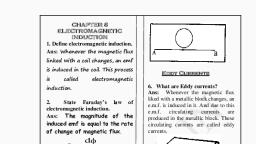
Note: The relation between charge flow and change in magnetic flux., According to Faraday’s law, e, , d B, dt, , d B, ------------------ (1), dt, , e , , but, , e Ir, , , , e , , Q V IR , dq , , I , , dt , , , dq, r ---------------- (2), dt, , From equation (1) and (2), , , e magnitude of emf, , d, dq, r B, dt, dt, , dqr = dB, dq , , d B, r, , Eddy currents:, These, , are, , the, , circulating, , currents, , induced in a bulk piece of conductor due to, change in magnetic flux linked with it., When, subjected, , to, , bulk, , piece, , varying, , of, , conductor, , magnetic, , flux,, , is, , then, , induced currents are produced in a conductor, like swirling eddies in water. These currents, are called eddy currents. Eddy current was, discovered by Foucault., A copper plate is allowed to swing between the pole pieces of strong, magnet as shown in figure. Now a magnetic flux through the plate changes, as, a results eddy currents are produced in the plate. According to Lenz’s law eddy, currents (induced currents) oppose the motion of a plate. Therefore oscillation, of plate is damped and finally the plate comes to rest.
Page 8 :
Note:, 1. If rectangular slots are made in the copper plate, as shown in figure area available to the flow of, eddy currents is less. Thus oscillated plate with, holes or slots reduces electromagnetic damping, and plate swings more freely., 2. Eddy currents are minimised in transformer or, electric motor by using laminations of metal to, make core. The laminations are separated by an, insulator., Advantages (Applications) of Eddy currents:, Eddy currents are used to advantage in certain, applications like,, 1. Magnetic braking in trains: Strong electromagnets are situated above the, rails in some electrically powered trains. When the electromagnets are, activated, the eddy currents induced in the rails oppose the motion of the, train. As there are no mechanical linkages, the braking effect is smooth., 2. Electromagnetic damping: Certain galvanometers have a fixed core made, of nonmagnetic metallic material. When the coil oscillates, the eddy, currents generated in the core oppose the motion and bring the coil to rest, quickly., 3. Induction furnace: Induction furnace can be used to produce high, temperatures and can be utilised to prepare alloys, by melting the, constituent metals. A high frequency alternating current is passed through, a coil which surrounds the metals to be melted. The eddy currents, generated in the metals produce high temperatures sufficient to melt it., 4. Electric power meters: The shiny metal disc in the electric power meter, (analogue type) rotates due to the eddy currents. Electric currents are, induced in the disc by magnetic fields produced by sinusoidally varying, currents in a coil. You can observe the rotating shiny disc in the power, meter of your house., Disadvantages of Eddy current:, 1. The production of eddy currents in a metallic block leads to the loss of, electric energy in the form of heat., 2. The heat produced due to eddy currents breaks the insulation used in the, electrical machine or appliances., 3. Eddy currents may cause unwanted dampening effect.
Page 9 :
Note 1) : If eddy current increases, the dissipation of electrical energy into heat, also increases i.e. energy lossI2, I=eddy current., Note 2) : We know that magnetic flux through a coil is directly proportional to, the current., i.e. B I ,, for N turns, NBI ,, If flux vary with time, then, , dB dI, , dt, dt, Mutual inductance: The phenomenon in which an emf is being induced in one, coil due to varying current in neighbouring coil is called Mutual inductance., Derive an expression for Mutual inductance [M]:, Consider two long co-axial solenoids S1 and S2 as shown in figure., Let, r1 = radius of s1, , r2 = radius of s 2, l = Length of s1 and s 2, , N1 = Number of turns of s1, n1 , , N1, =number of turns per unit, l, , length., , N 2 = Number of turns of s 2 ,, N2, = number of turns per unit length., l, Let I 2 be the current in S 2 . Therefore S 2 produces the magnetic field B 2 ., n2 , , Then magnetic flux linked with S1 is, , N11 M12 I2, , = BA cos , A = r2, =00, cos0 = 1, , N, M12 1 1 ------- (1), I2, , 1 B2 r12 , , N11I 2, , 1 B2 A1, , Where M12 = Mutual inductance of S1 w.r.t. S2, Let, 1=B2r12, but B2 = 0 n2 I2, 1 0 n 2 I2 r1, , 2, , eqn (1) becomes, , For solenoid, B=0nI
Page 11 :
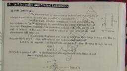
Derive the relation between induced emf and self inductance:, Consider a single coil having ‘N’ number of turns. When current ‘I’ through the, coil varies, then magnetic flux linked with the coil also varies. As a result an, e.m.f is induced in that coil., In this case, , NB I, Where B = magnetic flux linked with the coil, , NB LI, Where, L = co-efficient of self inductance of, the coil., According to Faraday’s law, , d N B , dt, d, e LI , dt, dI, e L, dt, e, , where, e = induced e.m.f., , Derive an expression for self Inductance (L) of a coil:, Consider a coil like solenoid, Let N = total number of turns in the coil, l = length of coil (solenoid), , n, , N, number of turns per unit length, l, , I = current flows, Magnetic field produced by the coil (solenoid) is, , B 0 nI, Magnetic flux, B BA, , B BA cos , but 00 , , , B BA, , , , B 0 nIA, Where A = cross sectional area of coil, We have NB LI, , n N l N nl , , nl 0 nIA LI, , L 0 n 2 Al, This is the expression for self inductance of a coil.
Page 12 :
Note:, 1) If we fill the inside of the solenoid (coil) with a material of relative, permeability r then L 0r n 2 Al, 2) L A i.e. self inductance (L) depends in its geometry, L r i.e L depends on permeability of medium., 3) The self induced e.m.f is also called the back e.m.f as it opposes any change, in the current in a circuit., Expression for the potential energy stored in a self inductance coil:, Consider a coil of self inductance ‘L’. The induced e.m.f (back e.m.f) in a, coil opposes any change in the current. So work is to be done in opposing the, back e.m.f. This work done is stored as magnetic potential energy., rate of work done =, , , , dw, eI, dt, , dw, dt, , e, , w, q, , W=eq, but q=It, , dI, dt, dw, dI, , LI, dt, dt, But e L, , W = e.I.t, , w, eI, t, Or, , dw = L I d I, Total work done is, , dw, eI, dt, , I, , dw LIdI, 0, I, , W L IdI, o, I, , I2 , W L , 2 o, L, W I 2 0 , 2, 1, W L I 2 This total workdone is stored as magnetic energy., 2, AC generator: It is a device which converts mechanical energy in to electrical, energy., AC generator was developed by Nicola Tesla.
Page 13 :
Principle of AC generator:, When a coil is rotated in a magnetic field, the effective area of a loop (coil), changes. As a result an e.m.f. is induced in the loop., Construction of AC generator:, The basic elements of an AC generator, are shown in figure. It consists of a coil, mounted on a rotor shaft. The axis of, rotation of the coil is perpendicular to the, direction of the magnetic field. The coil, [called armature] is mechanically rotated in, the uniform magnetic field. When a coil is, rotated, the magnetic flux through the coil, changes, so an e.m.f is induced in the coil., The ends of a coil are connected to an, external circuit by means of slip rings and, brushes., Theory of AC generator:, Let N = number of turns in the coil, A = Area of coil, , r, B uniform magnetic field, r, =angle between B and normal to A, , = angular velocity of coil, t, , , , =t, t=time, Effective area of coil = Acos, Flux through the coil is, B=NBAcos, , B=NBAcost, According to Faradays law, induced emf is, , e, , d B, dt, , e, , d NBA cos t , dt, , e NBA, , d cos t , dt, , e NBA sin t , e=NBAsint, , d cos , sin , dt
Page 14 :
e=emsint --------------- (1), where, em=NBA=Maximum value of emf (Peak value), but =2,, where =frequency of coil, , equation (1) becomes, e=em sin(2t), The induced emf varies from +em to em with time ‘t’ as shown below., , Note:, 1. In commercial generator, the mechanical energy required for rotation of the, armature is provided by water falling from height. These are called hydroelectric generators., 2. In some generators, the steam at high pressure produces the rotation of the, coil (armature). These are called thermal generators. In thermal generator,, steam is produced by coal or other sources., 3. Instead of coal, if a nuclear fuel is used to produce steam, then generators, are called nuclear power generator., 4. Modern day generators produce electric power as high as 500MW., 5. In most generators, the coil is held stationary and electromagnets are, rotated. The frequency of rotation is 50Hz in India. In USA it is 60 Hz., , ************
Page 15 :
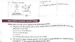
One Mark Questions:, 1. State Faraday’s law of electromagnetic induction. (March-2016), 2. Mention the significance of Lenz’s law (March-2015, 2016) (March 2017), 3. How can you minimize the loss due to eddy currents?, 4. What is mutual inductance?, 5. Mention the relation between induced emf and mutual inductance., 6. What is self induction? (July-2015), 7. What is AC generator?, 8. On which principle AC generator works?, 9. Give the expression for energy stored in a inductance coil carrying current, (March– 2014), 10. State Faraday’s law of electromagnetic induction ( July-2014), Two Mark Questions:, 1. State and explain Faraday’s law of induction. (March 2017), 2. What are eddy currents? Give one use of it (July-2014, 2015), 3. Mention any two advantage of eddy current in practical applications (March2014), 4. What is meant by self inductance and mutual inductance? (July-2016), 5. Current in a coil falls 2.5A to 0.0A in 0.1 second inducing an emf of 200V., Calculate the value of self inductance (March-2015), 6. The current in a coil of self inductance. 5mH changes from 2.5A to 2A in, 0.01 second. Calculate the value of self induced emf (March-2016)., Three Marks Questions:, 1. Explain briefly the coil and magnet experiment to demonstrate, electromagnetic induction (March-2016), 2. Explain briefly the coil-coil experiment., 3. Explain briefly coil-coil experiment without resistive motion to demonstrate, electromagnetic induction., 4. State and explain Lenz’s law for induced emf. (March-2014), 5. Derive an expression for electromotive force (motional emf) induced in a rod, moving perpendicular to the uniform magnetic field (July-2014), (March2015, July-2016, March 2017), 6. Derive an expression for mutual inductance or co – efficient of mutual, inductance., 7. Derive the relation between induced emf and self., 8. Derive an expression for self inductance (L) of a coil., 9. Derive the expression for energy stored in a current carrying coil (July-2015), 10. Describe the working of Ac generator., , *******
 Learn better on this topic