Notes of Class 11th, Physics NCERT11 Physics Part2Book - Study Material
Page 1 :
CHAPTER NINE, , MECHANICAL PROPERTIES, , 9.1, , 9.1, 9.2, 9.3, 9.4, 9.5, 9.6, 9.7, , Introduction, Elastic behaviour of solids, Stress and strain, Hooke’s law, Stress-strain curve, Elastic moduli, Applications of elastic, behaviour of materials, Summary, Points to ponder, Exercises, Additional exercises, , OF, , SOLIDS, , INTRODUCTION, , In Chapter 7, we studied the rotation of the bodies and then, realised that the motion of a body depends on how mass is, distributed within the body. We restricted ourselves to simpler, situations of rigid bodies. A rigid body generally means a, hard solid object having a definite shape and size. But in, reality, bodies can be stretched, compressed and bent. Even, the appreciably rigid steel bar can be deformed when a, sufficiently large external force is applied on it. This means, that solid bodies are not perfectly rigid., A solid has definite shape and size. In order to change (or, deform) the shape or size of a body, a force is required. If, you stretch a helical spring by gently pulling its ends, the, length of the spring increases slightly. When you leave the, ends of the spring, it regains its original size and shape. The, property of a body, by virtue of which it tends to regain its, original size and shape when the applied force is removed, is, known as elasticity and the deformation caused is known, as elastic deformation. However, if you apply force to a lump, of putty or mud, they have no gross tendency to regain their, previous shape, and they get permanently deformed. Such, substances are called plastic and this property is called, plasticity. Putty and mud are close to ideal plastics., The elastic behaviour of materials plays an important role, in engineering design. For example, while designing a, building, knowledge of elastic properties of materials like steel,, concrete etc. is essential. The same is true in the design of, bridges, automobiles, ropeways etc. One could also ask —, Can we design an aeroplane which is very light but, sufficiently strong? Can we design an artificial limb which, is lighter but stronger? Why does a railway track have a, particular shape like I? Why is glass brittle while brass is, not? Answers to such questions begin with the study of how, relatively simple kinds of loads or forces act to deform, different solids bodies. In this chapter, we shall study the, , 2019-20
Page 2 :
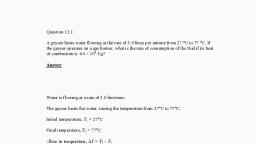
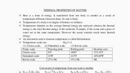
236, , PHYSICS, , elastic behaviour and mechanical properties of, solids which would answer many such, questions., 9.2 ELASTIC BEHAVIOUR OF SOLIDS, We know that in a solid, each atom or molecule, is surrounded by neighbouring atoms or, molecules. These are bonded together by, interatomic or intermolecular forces and stay, in a stable equilibrium position. When a solid is, deformed, the atoms or molecules are displaced, from their equilibrium positions causing a, change in the interatomic (or intermolecular), distances. When the deforming force is removed,, the interatomic forces tend to drive them back, to their original positions. Thus the body regains, its original shape and size. The restoring, mechanism can be visualised by taking a model, of spring-ball system shown in the Fig. 9.1. Here, the balls represent atoms and springs represent, interatomic forces., , Fig. 9.1 Spring-ball model for the illustration of elastic, behaviour of solids., , If you try to displace any ball from its, equilibrium position, the spring system tries to, restore the ball back to its original position. Thus, elastic behaviour of solids can be explained in, terms of microscopic nature of the solid. Robert, Hooke, an English physicist (1635 - 1703 A.D), performed experiments on springs and found, that the elongation (change in the length), produced in a body is proportional to the applied, force or load. In 1676, he presented his law of, , 2019-20, , elasticity, now called Hooke’s law. We shall, study about it in Section 9.4. This law, like, Boyle’s law, is one of the earliest quantitative, relationships in science. It is very important to, know the behaviour of the materials under, various kinds of load from the context of, engineering design., 9.3 STRESS AND STRAIN, When forces are applied on a body in such a, manner that the body is still in static equilibrium,, it is deformed to a small or large extent depending, upon the nature of the material of the body and, the magnitude of the deforming force. The, deformation may not be noticeable visually in, many materials but it is there. When a body is, subjected to a deforming force, a restoring force, is developed in the body. This restoring force is, equal in magnitude but opposite in direction to, the applied force. The restoring force per unit area, is known as stress. If F is the force applied normal, to the cross–section and A is the area of cross, section of the body,, Magnitude of the stress = F/A, (9.1), The SI unit of stress is N m–2 or pascal (Pa), and its dimensional formula is [ ML–1T–2 ]., There are three ways in which a solid may, change its dimensions when an external force, acts on it. These are shown in Fig. 9.2. In, Fig.9.2(a), a cylinder is stretched by two equal, forces applied normal to its cross-sectional area., The restoring force per unit area in this case, is called tensile stress. If the cylinder is, compressed under the action of applied forces,, the restoring force per unit area is known as, compressive stress. Tensile or compressive, stress can also be termed as longitudinal stress., In both the cases, there is a change in the, length of the cylinder. The change in the length, ∆L to the original length L of the body (cylinder, in this case) is known as longitudinal strain., Longitudinal strain =, , ∆L, L, , (9.2), , However, if two equal and opposite deforming, forces are applied parallel to the cross-sectional, area of the cylinder, as shown in Fig. 9.2(b),, there is relative displacement between the, opposite faces of the cylinder. The restoring force, per unit area developed due to the applied, tangential force is known as tangential or, shearing stress.
Page 3 :
MECHANICAL PROPERTIES OF SOLIDS, , 237, , Robert Hooke, (1635 – 1703 A.D.), Robert Hooke was born on July 18, 1635 in Freshwater, Isle of Wight. He was, one of the most brilliant and versatile seventeenth century English scientists., He attended Oxford University but never graduated. Yet he was an extremely, talented inventor, instrument-maker and building designer. He assisted Robert, Boyle in the construction of Boylean air pump. In 1662, he was appointed as, Curator of Experiments to the newly founded Royal Society. In 1665, he became, Professor of Geometry in Gresham College where he carried out his astronomical observations. He built a Gregorian reflecting telescope; discovered the fifth, star in the trapezium and an asterism in the constellation Orion; suggested that, Jupiter rotates on its axis; plotted detailed sketches of Mars which were later, used in the 19th century to determine the planet’s rate of rotation; stated the, inverse square law to describe planetary motion, which Newton modified later, etc. He was elected Fellow of Royal Society and also served as the Society’s, Secretary from 1667 to 1682. In his series of observations presented in Micrographia, he suggested, wave theory of light and first used the word ‘cell’ in a biological context as a result of his studies of cork., Robert Hooke is best known to physicists for his discovery of law of elasticity: Ut tensio, sic vis (This, is a Latin expression and it means as the distortion, so the force). This law laid the basis for studies of, stress and strain and for understanding the elastic materials., , As a result of applied tangential force, there, is a relative displacement ∆x between opposite, faces of the cylinder as shown in the Fig. 9.2(b)., The strain so produced is known as shearing, strain and it is defined as the ratio of relative, displacement of the faces ∆x to the length of, the cylinder L., Shearing strain =, , ∆x, = tan θ, L, , (9.3), , where θ is the angular displacement of the, cylinder from the vertical (original position of, the cylinder). Usually θ is very small, tan θ, is nearly equal to angle θ , (if θ = 10°, for, example, there is only 1% difference between θ, and tan θ)., , (a), Fig. 9.2, , It can also be visualised, when a book is, pressed with the hand and pushed horizontally,, as shown in Fig. 9.2 (c)., (9.4), Thus, shearing strain = tan θ ≈ θ, In Fig. 9.2 (d), a solid sphere placed in the, fluid under high pressure is compressed, uniformly on all sides. The force applied by the, fluid acts in perpendicular direction at each, point of the surface and the body is said to be, under hydraulic compression. This leads to, decrease in its volume without any change of, its geometrical shape., The body develops internal restoring forces, that are equal and opposite to the forces applied, by the fluid (the body restores its original shape, and size when taken out from the fluid). The, internal restoring force per unit area in this case, , (b), , (c), , (d), , (a) A cylindrical body under tensile stress elongates by ∆L (b) Shearing stress on a cylinder deforming it by, an angle θ (c) A body subjected to shearing stress (d) A solid body under a stress normal to the surface at, every point (hydraulic stress). The volumetric strain is ∆V/V, but there is no change in shape., , 2019-20
Page 4 :
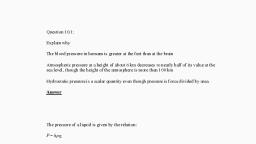
238, , PHYSICS, , is known as hydraulic stress and in magnitude, is equal to the hydraulic pressure (applied force, per unit area)., The strain produced by a hydraulic pressure, is called volume strain and is defined as the, ratio of change in volume (∆V) to the original, volume (V )., Volume strain =, , ∆V, V, , The body regains its original dimensions when, the applied force is removed. In this region, the, solid behaves as an elastic body., , (9.5), , Since the strain is a ratio of change in, dimension to the original dimension, it has no, units or dimensional formula., 9.4 HOOKE’S LAW, Stress and strain take different forms in the, situations depicted in the Fig. (9.2). For small, deformations the stress and strain are, proportional to each other. This is known as, Hooke’s law., Thus,, stress ∝ strain, stress = k × strain, (9.6), where k is the proportionality constant and is, known as modulus of elasticity., Hooke’s law is an empirical law and is found, to be valid for most materials. However, there, are some materials which do not exhibit this, linear relationship., 9.5 STRESS-STRAIN CURVE, The relation between the stress and the strain, for a given material under tensile stress can be, found experimentally. In a standard test of, tensile properties, a test cylinder or a wire is, stretched by an applied force. The fractional, change in length (the strain) and the applied, force needed to cause the strain are recorded., The applied force is gradually increased in steps, and the change in length is noted. A graph is, plotted between the stress (which is equal in, magnitude to the applied force per unit area), and the strain produced. A typical graph for a, metal is shown in Fig. 9.3. Analogous graphs, for compression and shear stress may also be, obtained. The stress-strain curves vary from, material to material. These curves help us to, understand how a given material deforms with, increasing loads. From the graph, we can see, that in the region between O to A, the curve is, linear. In this region, Hooke’s law is obeyed., , 2019-20, , Fig. 9.3 A typical stress-strain curve for a metal., , In the region from A to B, stress and strain, are not proportional. Nevertheless, the body still, returns to its original dimension when the load, is removed. The point B in the curve is known, as yield point (also known as elastic limit) and, the corresponding stress is known as yield, strength (σy ) of the material., If the load is increased further, the stress, developed exceeds the yield strength and strain, increases rapidly even for a small change in the, stress. The portion of the curve between B and, D shows this. When the load is removed, say at, some point C between B and D, the body does, not regain its original dimension. In this case,, even when the stress is zero, the strain is not, zero. The material is said to have a permanent, set. The deformation is said to be plastic, deformation. The point D on the graph is the, ultimate tensile strength (σu ) of the material., Beyond this point, additional strain is produced, even by a reduced applied force and fracture, occurs at point E. If the ultimate strength and, fracture points D and E are close, the material, is said to be brittle. If they are far apart, the, material is said to be ductile., As stated earlier, the stress-strain behaviour, varies from material to material. For example,, rubber can be pulled to several times its original, length and still returns to its original shape., Fig. 9.4 shows stress-strain curve for the elastic, tissue of aorta, present in the heart. Note that, although elastic region is very large, the material
Page 5 :
MECHANICAL PROPERTIES OF SOLIDS, , 239, , 9.6.1 Young’s Modulus, Experimental observation show that for a given, material, the magnitude of the strain produced, is same whether the stress is tensile or, compressive. The ratio of tensile (or compressive), stress (σ ) to the longitudinal strain (ε) is defined as, Young’s modulus and is denoted by the symbol Y., Y=, , σ, ε, , (9.7), , From Eqs. (9.1) and (9.2), we have, , Fig. 9.4, , Stress-strain curve for the elastic tissue of, Aorta, the large tube (vessel) carrying blood, from the heart., , does not obey Hooke’s law over most of the, region. Secondly, there is no well defined plastic, region. Substances like tissue of aorta, rubber, etc. which can be stretched to cause large strains, are called elastomers., 9.6 ELASTIC MODULI, The proportional region within the elastic limit, of the stress-strain curve (region OA in Fig. 9.3), is of great importance for structural and, manufacturing engineering designs. The ratio, of stress and strain, called modulus of elasticity,, is found to be a characteristic of the material., , Y = (F/A)/(∆L/L), = (F × L) /(A × ∆L), (9.8), Since strain is a dimensionless quantity, the, unit of Young’s modulus is the same as that of, stress i.e., N m–2 or Pascal (Pa). Table 9.1 gives, the values of Young’s moduli and yield strengths, of some material., From the data given in Table 9.1, it is noticed, that for metals Young’s moduli are large., Therefore, these materials require a large force, to produce small change in length. To increase, the length of a thin steel wire of 0.1 cm2 crosssectional area by 0.1%, a force of 2000 N is, required. The force required to produce the same, strain in aluminium, brass and copper wires, having the same cross-sectional area are 690 N,, 900 N and 1100 N respectively. It means that, steel is more elastic than copper, brass and, aluminium. It is for this reason that steel is, , Table 9.1 Young’s moduli and yield strenghs of some material, , # Substance tested under compression, , 2019-20
Page 6 :
240, , PHYSICS, , preferred in heavy-duty machines and in, structural designs. Wood, bone, concrete and, glass have rather small Young’s moduli., u Example 9.1 A structural steel rod has a, radius of 10 mm and a length of 1.0 m. A, 100 kN force stretches it along its length., Calculate (a) stress, (b) elongation, and (c), strain on the rod. Young’s modulus, of, structural steel is 2.0 × 10¹¹ N m-2., Answer We assume that the rod is held by a, clamp at one end, and the force F is applied at, the other end, parallel to the length of the rod., Then the stress on the rod is given by, Stress =, , F, A, , F, , =, , πr, , u Example 9.3 In a human pyramid in a, circus, the entire weight of the balanced, group is supported by the legs of a, performer who is lying on his back (as, shown in Fig. 9.5). The combined mass of, all the persons performing the act, and the, tables, plaques etc. involved is 280 kg. The, mass of the performer lying on his back at, the bottom of the pyramid is 60 kg. Each, thighbone (femur) of this performer has a, length of 50 cm and an effective radius of, 2.0 cm. Determine the amount by which, each thighbone gets compressed under the, extra load., , 2, 3, , 100 × 10 N, , =, , (, , 3.14 × 10, , −2, , m, , 2, , ), , = 3.18 × 10⁸ N m–2, The elongation,, ∆L =, , =, , ( F/A ) L, Y, , (3.18 × 10, , 8, , N m, , 11, , –2, , where the subscripts c and s refer to copper, and stainless steel respectively. Or,, ∆Lc/∆Ls = (Ys/Yc) × (Lc/Ls), Given Lc = 2.2 m, Ls = 1.6 m,, From Table 9.1 Yc = 1.1 × 10¹¹ N.m–2, and, Ys = 2.0 × 10¹¹ N.m–2., 11, ∆Lc/∆Ls = (2.0 × 10 /1.1 × 1011) × (2.2/1.6) = 2.5., The total elongation is given to be, ∆Lc + ∆Ls = 7.0 × 10⁻⁴ m, Solving the above equations,, ∆Lc = 5.0 × 10⁻⁴ m, and ∆Ls = 2.0 × 10⁻⁴ m., Therefore, W = (A × Yc × ∆Lc)/Lc, = π (1.5 × 10⁻³)2 × [(5.0 × 10-4 × 1.1 × 1011)/2.2], = 1.8 × 10² N, t, , ) (1m ), , –2, , 2 × 10 N m, = 1.59 × 10⁻³ m, = 1.59 mm, The strain is given by, Strain = ∆L/L, = (1.59 × 10⁻³ m)/(1m), = 1.59 × 10⁻³, = 0.16 %, , t, , u Example 9.2 A copper wire of length 2.2, m and a steel wire of length 1.6 m, both of, diameter 3.0 mm, are connected end to end., When stretched by a load, the net, elongation is found to be 0.70 mm. Obtain, the load applied., Answer The copper and steel wires are under, a tensile stress because they have the same, tension (equal to the load W) and the same area, of cross-section A. From Eq. (9.7) we have stress, = strain × Young’s modulus. Therefore, W/A = Yc × (∆Lc/Lc) = Ys × (∆Ls/Ls), , 2019-20, , Fig. 9.5 Human pyramid in a circus.
Page 7 :
MECHANICAL PROPERTIES OF SOLIDS, , Answer Total mass of all the performers, tables,, plaques etc., = 280 kg, Mass of the performer = 60 kg, Mass supported by the legs of the performer, at the bottom of the pyramid, = 280 – 60 = 220 kg, Weight of this supported mass, = 220 kg wt. = 220 × 9.8 N = 2156 N., Weight supported by each thighbone of the, performer = ½ (2156) N = 1078 N., From Table 9.1, the Young’s modulus for bone, is given by, Y, = 9.4 × 10⁹ N m–2., Length of each thighbone L = 0.5 m, the radius of thighbone = 2.0 cm, Thus the cross-sectional area of the thighbone, A = π × (2 × 10⁻²)2 m2 = 1.26 × 10⁻³ m2., Using Eq. (9.8), the compression in each, thighbone (∆L) can be computed as, ∆L, = [(F × L)/(Y × A)], = [(1078 × 0.5)/(9.4 × 109 × 1.26 × 10-3)], = 4.55 × 10⁻⁵ m or 4.55 × 10⁻³ cm., This is a very small change! The fractional, decrease in the thighbone is ∆L/L = 0.000091, or 0.0091%., t, 9.6.2 Determination of Young’s Modulus of, the Material of a Wire, A typical experimental arrangement to determine, the Young’s modulus of a material of wire under, tension is shown in Fig. 9.6. It consists of two, long straight wires of same length and equal, radius suspended side by side from a fixed rigid, support. The wire A (called the reference wire), carries a millimetre main scale M and a pan to, place a weight. The wire B (called the, experimental wire) of uniform area of crosssection also carries a pan in which known, weights can be placed. A vernier scale V is, attached to a pointer at the bottom of the, experimental wire B, and the main scale M is, fixed to the reference wire A. The weights placed, in the pan exert a downward force and stretch, the experimental wire under a tensile stress. The, elongation of the wire (increase in length) is, measured by the vernier arrangement. The, reference wire is used to compensate for any, change in length that may occur due to change, in room temperature, since any change in length, of the reference wire due to temperature change, , 241, , will be accompanied by an equal change in, experimental wire. (We shall study these, temperature effects in detail in Chapter 11.), , Fig. 9.6, , An arrangement for the determination of, Young’s modulus of the material of a wire., , Both the reference and experimental wires are, given an initial small load to keep the wires, straight and the vernier reading is noted. Now, the experimental wire is gradually loaded with, more weights to bring it under a tensile stress, and the vernier reading is noted again. The, difference between two vernier readings gives, the elongation produced in the wire. Let r and L, be the initial radius and length of the, experimental wire, respectively. Then the area, of cross-section of the wire would be πr2. Let M, be the mass that produced an elongation ∆L in, the wire. Thus the applied force is equal to Mg,, where g is the acceleration due to gravity. From, Eq. (9.8), the Young’s modulus of the material, of the experimental wire is given by, , Y=, , Mg L, σ, = π r 2 . ∆L, ε, , = Mg × L/(πr2 × ∆L), , 2019-20, , (9.9)
Page 8 :
242, , PHYSICS, , 9.6.3 Shear Modulus, The ratio of shearing stress to the corresponding, shearing strain is called the shear modulus of, the material and is represented by G. It is also, called the modulus of rigidity., G = shearing stress (σs)/shearing strain, G = (F/A)/(∆x/L), = (F × L)/(A × ∆x), (9.10), Similarly, from Eq. (9.4), G = (F/A)/θ, = F/(A × θ), (9.11), The shearing stress σs can also be expressed as, σs = G × θ, (9.12), SI unit of shear modulus is N m–2 or Pa. The, shear moduli of a few common materials are, given in Table 9.2. It can be seen that shear, modulus (or modulus of rigidity) is generally less, than Young’s modulus (from Table 9.1). For most, materials G ≈ Y/3., Table 9.2, , Shear moduli (G) of some common, materials, , Material, Aluminium, Brass, Copper, Glass, Iron, Lead, Nickel, Steel, Tungsten, Wood, , 9, , G (10 Nm, or GPa), , –2, , 25, 36, 42, 23, 70, 5.6, 77, 84, 150, 10, , u Example 9.4 A square lead slab of side 50, cm and thickness 10 cm is subject to a, shearing force (on its narrow face) of 9.0 ×, 104 N. The lower edge is riveted to the floor., How much will the upper edge be displaced?, Answer The lead slab is fixed and the force is, applied parallel to the narrow face as shown in, Fig. 9.7. The area of the face parallel to which, this force is applied is, A = 50 cm × 10 cm, = 0.5 m × 0.1 m, = 0.05 m2, , 2019-20, , Therefore, the stress applied is, = (9.4 × 10⁴ N/0.05 m2), = 1.80 × 10⁶ N.m–2, , aaaaaaaaaaaaaaaaaaaaa, aaaaaaaaaaaaaaaaaaaaa, Fig. 9.7, , We know that shearing strain = (∆x/L)= Stress /G., Therefore the displacement ∆x = (Stress × L)/G, = (1.8 × 10⁶ N m–2 × 0.5m)/(5.6 × 109 N m–2), = 1.6 × 10⁻⁴ m = 0.16 mm, t, 9.6.4 Bulk Modulus, In Section (9.3), we have seen that when a body, is submerged in a fluid, it undergoes a hydraulic, stress (equal in magnitude to the hydraulic, pressure). This leads to the decrease in the, volume of the body thus producing a strain called, volume strain [Eq. (9.5)]. The ratio of hydraulic, stress to the corresponding hydraulic strain is, called bulk modulus. It is denoted by symbol B., B = – p/(∆V/V), (9.13), The negative sign indicates the fact that with, an increase in pressure, a decrease in volume, occurs. That is, if p is positive, ∆V is negative., Thus for a system in equilibrium, the value of, bulk modulus B is always positive. SI unit of, bulk modulus is the same as that of pressure, i.e., N m–2 or Pa. The bulk moduli of a few, common materials are given in Table 9.3., The reciprocal of the bulk modulus is called, compressibility and is denoted by k. It is defined, as the fractional change in volume per unit, increase in pressure., k = (1/B) = – (1/∆p) × (∆V/V), (9.14), It can be seen from the data given in Table, 9.3 that the bulk moduli for solids are much, larger than for liquids, which are again much, larger than the bulk modulus for gases (air).
Page 9 :
MECHANICAL PROPERTIES OF SOLIDS, , Table 9.3, , Bulk moduli (B) of some common, Materials, , B (109 N m–2 or GPa), , Material, Solids, Aluminium, , 72, , Brass, Copper, , 61, 140, , Glass, Iron, , 37, 100, , Nickel, Steel, , 260, 160, , Liquids, Water, , 2.2, , Ethanol, Carbon disulphide, , 0.9, 1.56, , Glycerine, Mercury, , 4.76, 25, , Gases, Air (at STP), , 1.0 × 10⁻⁴, , Thus, solids are the least compressible, whereas,, gases are the most compressible. Gases are about, a million times more compressible than solids!, , 243, , Gases have large compressibilities, which vary, with pressure and temperature. The, incompressibility of the solids is primarily due, to the tight coupling between the neighbouring, atoms. The molecules in liquids are also bound, with their neighbours but not as strong as in, solids. Molecules in gases are very poorly, coupled to their neighbours., Table 9.4 shows the various types of stress,, strain, elastic moduli, and the applicable state, of matter at a glance., u Example 9.5 The average depth of Indian, Ocean is about 3000 m. Calculate the, fractional compression, ∆V/V, of water at, the bottom of the ocean, given that the bulk, modulus of water is 2.2 × 10⁹ N m–2. (Take, g = 10 m s–2), Answer The pressure exerted by a 3000 m, column of water on the bottom layer, p = hρ g = 3000 m × 1000 kg m–3 × 10 m s–2, = 3 × 10⁷ kg m–1 s-2, = 3 × 10⁷ N m–2, Fractional compression ∆V/V, is, ∆V/V = stress/B = (3 × 10⁷ N m-2)/(2.2 × 109 N m–2), = 1.36 × 10⁻² or 1.36 %, t, , Table 9.4 Stress, strain and various elastic moduli, Type of, stress, , Stress, , Strain, , Change in, shape volume, , Elastic, Modulus, , Name of, Modulus, , State of, Matter, , Tensile, or, compressive, (σ = F/A), , Two equal and, opposite forces, perpendicular to, opposite faces, , Elongation or, compression, parallel to force, direction (∆L/L), (longitudinal strain), , Yes, , No, , Y = (F×L)/, (A×∆L), , Young’s, modulus, , Solid, , Shearing, (σs = F/A), , Two equal and, opposite forces, parallel to oppoiste, surfaces forces, in each case such, that total force and, total torque on the, body vanishes, , Pure shear, θ, , Yes, , No, , G = F/(A×θ), , Hydraulic, , Forces perpendicular, everywhere to the, surface, force per, unit area (pressure), same everywhere., , Volume change, (compression or, elongation), (∆V/V), , No, , Yes, , 2019-20, , Shear, Solid, modulus, or modulus, of rigidity, , B = –p/(∆V/V) Bulk, modulus, , Solid, liquid, and gas
Page 10 :
244, , PHYSICS, , 9.6.5 POISSON’S RATIO, Careful observations with the Young’s modulus, experiment (explained in section 9.6.2), show, that there is also a slight reduction in the crosssection (or in the diameter) of the wire. The strain, perpendicular to the applied force is called, lateral strain. Simon Poisson pointed out that, within the elastic limit, lateral strain is directly, proportional to the longitudinal strain. The ratio, of the lateral strain to the longitudinal strain in, a stretched wire is called Poisson’s ratio. If the, original diameter of the wire is d and the, contraction of the diameter under stress is ∆d,, the lateral strain is ∆d/d. If the original length, of the wire is L and the elongation under stress, is ∆L, the longitudinal strain is ∆L/L. Poisson’s, ratio is then (∆d/d)/(∆L/L) or (∆d/∆L) × (L/d)., Poisson’s ratio is a ratio of two strains; it is a, pure number and has no dimensions or units., Its value depends only on the nature of material., For steels the value is between 0.28 and 0.30,, and for aluminium alloys it is about 0.33., 9.6.6 Elastic Potential Energy, in a Stretched Wire, When a wire is put under a tensile stress, work, is done against the inter-atomic forces. This, work is stored in the wire in the form of elastic, potential energy. When a wire of original length, L and area of cross-section A is subjected to a, deforming force F along the length of the wire,, let the length of the wire be elongated by l. Then, from Eq. (9.8), we have F = YA × (l/L). Here Y is, the Young’s modulus of the material of the wire., Now for a further elongation of infinitesimal, small length dl, work done dW is F × dl or YAldl/, L. Therefore, the amount of work done (W) in, increasing the length of the wire from L to L + l,, that is from l = 0 to l = l is, W=, , l, , ∫0, , YAl, YA l 2, dl =, ×, L, 2, L, 2, , 1, l , W = × Y × × AL, 2, L , =, , 1, × Young’s modulus × strain2 ×, 2, volume of the wire, , 2019-20, , 1, × stress × strain × volume of the, 2, wire, This work is stored in the wire in the form of, elastic potential energy (U). Therefore the elastic, potential energy per unit volume of the wire (u) is, =, , u=, 9.7, , 1, ×σε, 2, , (9.15), , APPLICATIONS OF ELASTIC, BEHAVIOUR OF MATERIALS, , The elastic behaviour of materials plays an, important role in everyday life. All engineering, designs require precise knowledge of the elastic, behaviour of materials. For example while, designing a building, the structural design of, the columns, beams and supports require, knowledge of strength of materials used. Have, you ever thought why the beams used in, construction of bridges, as supports etc. have, a cross-section of the type I? Why does a heap, of sand or a hill have a pyramidal shape?, Answers to these questions can be obtained, from the study of structural engineering which, is based on concepts developed here., Cranes used for lifting and moving heavy, loads from one place to another have a thick, metal rope to which the load is attached. The, rope is pulled up using pulleys and motors., Suppose we want to make a crane, which has, a lifting capacity of 10 tonnes or metric tons (1, metric ton = 1000 kg). How thick should the, steel rope be? We obviously want that the load, does not deform the rope permanently., Therefore, the extension should not exceed the, elastic limit. From Table 9.1, we find that mild, steel has a yield strength (σy) of about 300 ×, 106 N m–2. Thus, the area of cross-section (A), of the rope should at least be, A ≥ W/σy = Mg/σy, (9.16), = (104 kg × 9.8 m s-2)/(300 × 106 N m-2), = 3.3 × 10⁻⁴ m2, corresponding to a radius of about 1 cm for, a rope of circular cross-section. Generally, a large margin of safety (of about a factor of, ten in the load) is provided. Thus a thicker, rope of radius about 3 cm is recommended., A single wire of this radius would practically, be a rigid rod. So the ropes are always made, of a number of thin wires braided together,
Page 11 :
MECHANICAL PROPERTIES OF SOLIDS, , 245, , like in pigtails, for ease in manufacture,, flexibility and strength., A bridge has to be designed such that it can, withstand the load of the flowing traffic, the force, of winds and its own weight. Similarly, in the, design of buildings the use of beams and columns, is very common. In both the cases, the, overcoming of the problem of bending of beam, under a load is of prime importance. The beam, should not bend too much or break. Let us, consider the case of a beam loaded at the centre, and supported near its ends as shown in, Fig. 9.8. A bar of length l, breadth b, and depth d, when loaded at the centre by a load W sags by, an amount given by, , δ = W l 3/(4bd 3Y), , Fig. 9.8, , (9.17), , (a), Fig. 9.9, , (b), , (c), , Different cross-sectional shapes of a beam., (a) Rectangular section of a bar;, (b) A thin bar and how it can buckle;, (c) Commonly used section for a load, bearing bar., , The use of pillars or columns is also very, common in buildings and bridges. A pillar with, rounded ends as shown in Fig. 9.10(a) supports, less load than that with a distributed shape at, the ends [Fig. 9.10(b)]. The precise design of a, bridge or a building has to take into account, the conditions under which it will function, the, cost and long period, reliability of usable, material, etc., , A beam supported at the ends and loaded, at the centre., , This relation can be derived using what you, have already learnt and a little calculus. From, Eq. (9.16), we see that to reduce the bending, for a given load, one should use a material with, a large Young’s modulus Y. For a given material,, increasing the depth d rather than the breadth, b is more effective in reducing the bending, since, δ is proportional to d -3 and only to b-1(of course, the length l of the span should be as small as, possible). But on increasing the depth, unless, the load is exactly at the right place (difficult to, arrange in a bridge with moving traffic), the, deep bar may bend as shown in Fig. 9.9(b). This, is called buckling. To avoid this, a common, compromise is the cross-sectional shape shown, in Fig. 9.9(c). This section provides a large loadbearing surface and enough depth to prevent, bending. This shape reduces the weight of the, beam without sacrificing the strength and, hence reduces the cost., , (a), Fig. 9.10, , (b), , Pillars or columns: (a) a pillar with rounded, ends, (b) Pillar with distributed ends., , The answer to the question why the maximum, height of a mountain on earth is ~10 km can, also be provided by considering the elastic, properties of rocks. A mountain base is not under, uniform compression and this provides some, shearing stress to the rocks under which they, can flow. The stress due to all the material on, the top should be less than the critical shearing, stress at which the rocks flow., At the bottom of a mountain of height h, the, force per unit area due to the weight of the, mountain is hρg where ρ is the density of the, material of the mountain and g is the acceleration, , 2019-20
Page 12 :
246, , PHYSICS, , due to gravity. The material at the bottom, experiences this force in the vertical direction,, and the sides of the mountain are free. Therefore,, this is not a case of pressure or bulk compression., There is a shear component, approximately hρg, itself. Now the elastic limit for a typical rock is, , 30 × 107 N m-2. Equating this to hρg, with, ρ = 3 × 10³ kg m-3 gives, hρg = 30 × 107 N m-2 ., h, = 30 × 107 N m-2/(3 × 103 kg m-3 × 10 m s-2), = 10 km, which is more than the height of Mt. Everest!, , SUMMARY, 1., , 2., , 3., , 4., , 5., , Stress is the restoring force per unit area and strain is the fractional change in dimension., In general there are three types of stresses (a) tensile stress — longitudinal stress, (associated with stretching) or compressive stress (associated with compression),, (b) shearing stress, and (c) hydraulic stress., For small deformations, stress is directly proportional to the strain for many materials., This is known as Hooke’s law. The constant of proportionality is called modulus of, elasticity. Three elastic moduli viz., Young’s modulus, shear modulus and bulk modulus, are used to describe the elastic behaviour of objects as they respond to deforming forces, that act on them., A class of solids called elastomers does not obey Hooke’s law., When an object is under tension or compression, the Hooke’s law takes the form, F/A = Y∆L/L, where ∆L/L is the tensile or compressive strain of the object, F is the magnitude of the, applied force causing the strain, A is the cross-sectional area over which F is applied, (perpendicular to A) and Y is the Young’s modulus for the object. The stress is F/A., A pair of forces when applied parallel to the upper and lower faces, the solid deforms so, that the upper face moves sideways with respect to the lower. The horizontal displacement, ∆L of the upper face is perpendicular to the vertical height L. This type of deformation is, called shear and the corresponding stress is the shearing stress. This type of stress is, possible only in solids., In this kind of deformation the Hooke’s law takes the form, F/A = G × ∆L/L, where ∆L is the displacement of one end of object in the direction of the applied force F,, and G is the shear modulus., When an object undergoes hydraulic compression due to a stress exerted by a surrounding, fluid, the Hooke’s law takes the form, p = B (∆V/V),, where p is the pressure (hydraulic stress) on the object due to the fluid, ∆V/V (the, volume strain) is the absolute fractional change in the object’s volume due to that, pressure and B is the bulk modulus of the object., , POINTS TO PONDER, 1., , In the case of a wire, suspended from celing and stretched under the action of a weight (F), suspended from its other end, the force exerted by the ceiling on it is equal and opposite, to the weight. However, the tension at any cross-section A of the wire is just F and not, 2F. Hence, tensile stress which is equal to the tension per unit area is equal to F/A., , 2., , Hooke’s law is valid only in the linear part of stress-strain curve., , 3., , The Young’s modulus and shear modulus are relevant only for solids since only solids, have lengths and shapes., , 4., , Bulk modulus is relevant for solids, liquid and gases. It refers to the change in volume, when every part of the body is under the uniform stress so that the shape of the body, remains unchanged., , 2019-20
Page 13 :
MECHANICAL PROPERTIES OF SOLIDS, , 247, , 5., , Metals have larger values of Young’s modulus than alloys and elastomers. A material, with large value of Young’s modulus requires a large force to produce small changes in, its length., , 6., , In daily life, we feel that a material which stretches more is more elastic, but it a is, misnomer. In fact material which stretches to a lesser extent for a given load is considered, to be more elastic., , 7., , In general, a deforming force in one direction can produce strains in other directions, also. The proportionality between stress and strain in such situations cannot be described, by just one elastic constant. For example, for a wire under longitudinal strain, the, lateral dimensions (radius of cross section) will undergo a small change, which is described, by another elastic constant of the material (called Poisson ratio)., , 8., , Stress is not a vector quantity since, unlike a force, the stress cannot be assigned a, specific direction. Force acting on the portion of a body on a specified side of a section, has a definite direction., EXERCISES, , 9.1, , A steel wire of length 4.7 m and cross-sectional area 3.0 × 10⁻⁵ m2 stretches by the same, amount as a copper wire of length 3.5 m and cross-sectional area of 4.0 × 10⁻⁵ m2 under, a given load. What is the ratio of the Young’s modulus of steel to that of copper?, , 9.2, , Figure 9.11 shows the strain-stress curve for a given material. What are (a) Young’s, modulus and (b) approximate yield strength for this material?, , 9.3, , Fig. 9.11, The stress-strain graphs for materials A and B are shown in Fig. 9.12., , Fig. 9.12, , 2019-20
Page 14 :
248, , PHYSICS, , The graphs are drawn to the same scale., (a) Which of the materials has the greater Young’s modulus?, (b) Which of the two is the stronger material?, 9.4, , Read the following two statements below carefully and state, with reasons, if it is true, or false., (a) The Young’s modulus of rubber is greater than that of steel;, (b) The stretching of a coil is determined by its shear modulus., , 9.5 Two wires of diameter 0.25 cm, one made of steel and the other made of brass are, loaded as shown in Fig. 9.13. The unloaded length of steel wire is 1.5 m and that of, brass wire is 1.0 m. Compute the elongations of the steel and the brass wires., , 9.6, , 9.7, , 9.8, , 9.9, 9.10, , 9.11, , 9.12, , 9.13, 9.14, 9.15, 9.16, , Fig. 9.13, The edge of an aluminium cube is 10 cm long. One face of the cube is firmly fixed to a, vertical wall. A mass of 100 kg is then attached to the opposite face of the cube. The, shear modulus of aluminium is 25 GPa. What is the vertical deflection of this face?, Four identical hollow cylindrical columns of mild steel support a big structure of mass, 50,000 kg. The inner and outer radii of each column are 30 and 60 cm respectively., Assuming the load distribution to be uniform, calculate the compressional strain of, each column., A piece of copper having a rectangular cross-section of 15.2 mm × 19.1 mm is pulled in, tension with 44,500 N force, producing only elastic deformation. Calculate the resulting, strain?, A steel cable with a radius of 1.5 cm supports a chairlift at a ski area. If the maximum, stress is not to exceed 108 N m–2, what is the maximum load the cable can support ?, A rigid bar of mass 15 kg is supported symmetrically by three wires each 2.0 m long., Those at each end are of copper and the middle one is of iron. Determine the ratios of, their diameters if each is to have the same tension., A 14.5 kg mass, fastened to the end of a steel wire of unstretched length 1.0 m, is, whirled in a vertical circle with an angular velocity of 2 rev/s at the bottom of the circle., The cross-sectional area of the wire is 0.065 cm2. Calculate the elongation of the wire, when the mass is at the lowest point of its path., Compute the bulk modulus of water from the following data: Initial volume = 100.0, litre, Pressure increase = 100.0 atm (1 atm = 1.013 × 10⁵ Pa), Final volume = 100.5, litre. Compare the bulk modulus of water with that of air (at constant temperature)., Explain in simple terms why the ratio is so large., What is the density of water at a depth where pressure is 80.0 atm, given that its, density at the surface is 1.03 × 10³ kg m–3?, Compute the fractional change in volume of a glass slab, when subjected to a hydraulic, pressure of 10 atm., Determine the volume contraction of a solid copper cube, 10 cm on an edge, when, subjected to a hydraulic pressure of 7.0 × 10⁶ Pa., How much should the pressure on a litre of water be changed to compress it by 0.10%?, , 2019-20
Page 15 :
MECHANICAL PROPERTIES OF SOLIDS, , 249, , Additional Exercises, 9.17 Anvils made of single crystals of diamond, with the shape as shown in, Fig. 9.14, are used to investigate behaviour of materials under very high pressures. Flat, faces at the narrow end of the anvil have a diameter of 0.50 mm, and the wide ends are, subjected to a compressional force of 50,000 N. What is the pressure at the tip of the anvil?, , Fig. 9.14, 9.18 A rod of length 1.05 m having negligible mass is supported at its ends by two wires of, steel (wire A) and aluminium (wire B) of equal lengths as shown in, Fig. 9.15. The cross-sectional areas of wires A and B are 1.0 mm2 and 2.0 mm2,, respectively. At what point along the rod should a mass m be suspended in order to, produce (a) equal stresses and (b) equal strains in both steel and aluminium wires., , Fig. 9.15, 9.19 A mild steel wire of length 1.0 m and cross-sectional area 0.50 × 10⁻² cm2 is, stretched, well within its elastic limit, horizontally between two pillars. A mass of 100, g is suspended from the mid-point of the wire. Calculate the depression at the midpoint., 9.20 Two strips of metal are riveted together at their ends by four rivets, each of diameter 6.0, mm. What is the maximum tension that can be exerted by the riveted strip if the, shearing stress on the rivet is not to exceed 6.9 × 10⁷ Pa? Assume that each rivet is to, carry one quarter of the load., 9.21 The Marina trench is located in the Pacific Ocean, and at one place it is nearly eleven, km beneath the surface of water. The water pressure at the bottom of the trench is, about 1.1 × 10⁸ Pa. A steel ball of initial volume 0.32 m3 is dropped into the ocean and, falls to the bottom of the trench. What is the change in the volume of the ball when it, reaches to the bottom?, , 2019-20
Page 16 :
CHAPTER TEN, , MECHANICAL PROPERTIES, , OF, , FLUIDS, , 10.1 INTRODUCTION, , 10.1, 10.2, 10.3, 10.4, 10.5, 10.6, , Introduction, Pressure, Streamline flow, Bernoulli’s principle, Viscosity, Surface tension, Summary, Points to ponder, Exercises, Additional exercises, Appendix, , In this chapter, we shall study some common physical, properties of liquids and gases. Liquids and gases can flow, and are therefore, called fluids. It is this property that, distinguishes liquids and gases from solids in a basic way., Fluids are everywhere around us. Earth has an envelop of, air and two-thirds of its surface is covered with water. Water, is not only necessary for our existence; every mammalian, body constitute mostly of water. All the processes occurring, in living beings including plants are mediated by fluids. Thus, understanding the behaviour and properties of fluids is, important., How are fluids different from solids? What is common in, liquids and gases? Unlike a solid, a fluid has no definite, shape of its own. Solids and liquids have a fixed volume,, whereas a gas fills the entire volume of its container. We, have learnt in the previous chapter that the volume of solids, can be changed by stress. The volume of solid, liquid or gas, depends on the stress or pressure acting on it. When we, talk about fixed volume of solid or liquid, we mean its volume, under atmospheric pressure. The difference between gases, and solids or liquids is that for solids or liquids the change, in volume due to change of external pressure is rather small., In other words solids and liquids have much lower, compressibility as compared to gases., Shear stress can change the shape of a solid keeping its, volume fixed. The key property of fluids is that they offer, very little resistance to shear stress; their shape changes by, application of very small shear stress. The shearing stress, of fluids is about million times smaller than that of solids., 10.2 PRESSURE, A sharp needle when pressed against our skin pierces it. Our, skin, however, remains intact when a blunt object with a, wider contact area (say the back of a spoon) is pressed against, it with the same force. If an elephant were to step on a man’s, chest, his ribs would crack. A circus performer across whose, , 2019-20
Page 17 :
MECHANICAL PROPERTIES OF FLUIDS, , 251, , chest a large, light but strong wooden plank is, placed first, is saved from this accident. Such, everyday experiences convince us that both the, force and its coverage area are important. Smaller, the area on which the force acts, greater is the, impact. This impact is known as pressure., When an object is submerged in a fluid at, rest, the fluid exerts a force on its surface. This, force is always normal to the object’s surface., This is so because if there were a component of, force parallel to the surface, the object will also, exert a force on the fluid parallel to it; as a, consequence of Newton’s third law. This force, will cause the fluid to flow parallel to the surface., Since the fluid is at rest, this cannot happen., Hence, the force exerted by the fluid at rest has, to be perpendicular to the surface in contact, with it. This is shown in Fig.10.1(a)., The normal force exerted by the fluid at a point, may be measured. An idealised form of one such, pressure-measuring device is shown in Fig., 10.1(b). It consists of an evacuated chamber with, a spring that is calibrated to measure the force, acting on the piston. This device is placed at a, point inside the fluid. The inward force exerted, by the fluid on the piston is balanced by the, outward spring force and is thereby measured., , (a), (b), Fig. 10.1 (a) The force exerted by the liquid in the, beaker on the submerged object or on the, walls is normal (perpendicular) to the, surface at all points., (b) An idealised device for measuring, pressure., , In principle, the piston area can be made, arbitrarily small. The pressure is then defined, in a limiting sense as, P=, , F, A, , ∆F, ∆A, , (10.2), , Pressure is a scalar quantity. We remind the, reader that it is the component of the force, normal to the area under consideration and not, the (vector) force that appears in the numerator, in Eqs. (10.1) and (10.2). Its dimensions are, [ML–1T–2]. The SI unit of pressure is N m–2. It has, been named as pascal (Pa) in honour of the, French scientist Blaise Pascal (1623-1662) who, carried out pioneering studies on fluid pressure., A common unit of pressure is the atmosphere, (atm), i.e. the pressure exerted by the, atmosphere at sea level (1 atm = 1.013 × 10⁵ Pa)., Another quantity, that is indispensable in, describing fluids, is the density ρ . For a fluid of, mass m occupying volume V,, m, ρ=, (10.3), V, –3, The dimensions of density are [ML ]. Its SI, unit is kg m–3. It is a positive scalar quantity. A, liquid is largely incompressible and its density, is therefore, nearly constant at all pressures., Gases, on the other hand exhibit a large, variation in densities with pressure., The density of water at 4 o C (277 K) is, 1.0 × 10³ kg m–3. The relative density of a, substance is the ratio of its density to the, density of water at 4oC. It is a dimensionless, positive scalar quantity. For example the relative, density of aluminium is 2.7. Its density is, 2.7 × 10³ kg m–3. The densities of some common, fluids are displayed in Table 10.1., Table 10.1 Densities of some common fluids, at STP*, , If F is the magnitude of this normal force on the, piston of area A then the average pressure Pav, is defined as the normal force acting per unit, area., Pav =, , lim, ∆A →0, , (10.1), , * STP means standard temperature (00C) and 1 atm pressure., , 2019-20
Page 18 :
252, , PHYSICS, , Example 10.1, The two thigh bones, (femurs), each of cross-sectional area10 cm2, support the upper part of a human body of, mass 40 kg. Estimate the average pressure, sustained by the femurs., , t, , Answer, Total cross-sectional area of the, femurs is A = 2 × 10 cm2 = 20 × 10–4 m2. The, force acting on them is F = 40 kg wt = 400 N, (taking g = 10 m s –2). This force is acting, vertically down and hence, normally on the, femurs. Thus, the average pressure is, Pav =, , F, = 2 × 10⁵ N m −2, A, , t, , 10.2.1 Pascal’s Law, The French scientist Blaise Pascal observed that, the pressure in a fluid at rest is the same at all, points if they are at the same height. This fact, may be demonstrated in a simple way., , this element of area corresponding to the normal, forces Fa, Fb and Fc as shown in Fig. 10.2 on the, faces BEFC, ADFC and ADEB denoted by Aa, Ab, and Ac respectively. Then, Fb sinθ = Fc,, Fb cosθ = Fa (by equilibrium), Ab sinθ = Ac, Ab cosθ = Aa (by geometry), Thus,, Fb Fc, F, =, = a ;, Ab Ac Aa, , Pb = Pc = Pa, , (10.4), , Hence, pressure exerted is same in all, directions in a fluid at rest. It again reminds us, that like other types of stress, pressure is not a, vector quantity. No direction can be assigned, to it. The force against any area within (or, bounding) a fluid at rest and under pressure is, normal to the area, regardless of the orientation, of the area., Now consider a fluid element in the form of a, horizontal bar of uniform cross-section. The bar, is in equilibrium. The horizontal forces exerted, at its two ends must be balanced or the, pressure at the two ends should be equal. This, proves that for a liquid in equilibrium the, pressure is same at all points in a horizontal, plane. Suppose the pressure were not equal in, different parts of the fluid, then there would be, a flow as the fluid will have some net force, acting on it. Hence in the absence of flow the, pressure in the fluid must be same everywhere, in a horizontal plane., 10.2.2 Variation of Pressure with Depth, , Fig. 10.2 Proof of Pascal’s law. ABC-DEF is an, element of the interior of a fluid at rest., This element is in the form of a rightangled prism. The element is small so that, the effect of gravity can be ignored, but it, has been enlarged for the sake of clarity., , Fig. 10.2 shows an element in the interior of, a fluid at rest. This element ABC-DEF is in the, form of a right-angled prism. In principle, this, prismatic element is very small so that every, part of it can be considered at the same depth, from the liquid surface and therefore, the effect, of the gravity is the same at all these points., But for clarity we have enlarged this element., The forces on this element are those exerted by, the rest of the fluid and they must be normal to, the surfaces of the element as discussed above., Thus, the fluid exerts pressures Pa, Pb and Pc on, , 2019-20, , Consider a fluid at rest in a container. In, Fig. 10.3 point 1 is at height h above a point 2., The pressures at points 1 and 2 are P1 and P2, respectively. Consider a cylindrical element of, fluid having area of base A and height h. As the, fluid is at rest the resultant horizontal forces, should be zero and the resultant vertical forces, should balance the weight of the element. The, forces acting in the vertical direction are due to, the fluid pressure at the top (P 1A) acting, downward, at the bottom (P2A) acting upward., If mg is weight of the fluid in the cylinder we, have, (P2 − P1) A = mg, (10.5), Now, if ρ is the mass density of the fluid, we, have the mass of fluid to be m = ρV= ρhA so, that, P2 −P1= ρgh, (10.6)
Page 19 :
MECHANICAL PROPERTIES OF FLUIDS, , 253, , Fig 10.4 Illustration of hydrostatic paradox. The, three vessels A, B and C contain different, amounts of liquids, all upto the same, height., , t, Fig.10.3 Fluid under gravity. The effect of gravity is, illustrated through pressure on a vertical, cylindrical column., , Pressure difference depends on the vertical, distance h between the points (1 and 2), mass, density of the fluid ρ and acceleration due to, gravity g. If the point 1 under discussion is, shifted to the top of the fluid (say, water), which, is open to the atmosphere, P1 may be replaced, by atmospheric pressure (Pa) and we replace P2, by P. Then Eq. (10.6) gives, P = Pa + ρgh, , (10.7), , Thus, the pressure P, at depth below the, surface of a liquid open to the atmosphere is, greater than atmospheric pressure by an, amount ρgh. The excess of pressure, P −Pa, at, depth h is called a gauge pressure at that point., The area of the cylinder is not appearing in, the expression of absolute pressure in Eq. (10.7)., Thus, the height of the fluid column is important, and not cross-sectional or base area or the shape, of the container. The liquid pressure is the same, at all points at the same horizontal level (same, depth). The result is appreciated through the, example of hydrostatic paradox. Consider three, vessels A, B and C [Fig.10.4] of different shapes., They are connected at the bottom by a horizontal, pipe. On filling with water, the level in the three, vessels is the same, though they hold different, amounts of water. This is so because water at, the bottom has the same pressure below each, section of the vessel., , Example 10.2 What is the pressure on a, swimmer 10 m below the surface of a lake?, , Answer Here, h = 10 m and ρ = 1000 kg m-3. Take g = 10 m s–2, From Eq. (10.7), P = Pa + ρgh, = 1.01 × 10⁵ Pa + 1000 kg m–3 × 10 m s–2 × 10 m, = 2.01 × 10⁵ Pa, ≈ 2 atm, This is a 100% increase in pressure from, surface level. At a depth of 1 km, the increase, in pressure is 100 atm! Submarines are designed, to withstand such enormous pressures., t, 10.2.3 Atmospheric Pressure and, Gauge Pressure, The pressure of the atmosphere at any point is, equal to the weight of a column of air of unit, cross-sectional area extending from that point, to the top of the atmosphere. At sea level, it is, 1.013 × 10 5 Pa (1 atm). Italian scientist, Evangelista Torricelli (1608 –1647) devised for, the first time a method for measuring, atmospheric pressure. A long glass tube closed, at one end and filled with mercury is inverted, into a trough of mercury as shown in Fig.10.5 (a)., This device is known as ‘mercury barometer’., The space above the mercury column in the tube, contains only mercury vapour whose pressure, P is so small that it may be neglected. Thus,, the pressure at Point A=0. The pressure inside, the coloumn at Point B must be the same as the, pressure at Point C, which is atmospheric, pressure, Pa., Pa = ρgh, (10.8), where ρ is the density of mercury and h is the, height of the mercury column in the tube., , 2019-20
Page 20 :
254, , PHYSICS, , (b) The open tube manometer, Fig 10.5 Two pressure measuring devices., , Pressure is same at the same level on both, sides of the U-tube containing a fluid. For, liquids, the density varies very little over wide, ranges in pressure and temperature and we can, treat it safely as a constant for our present, purposes. Gases on the other hand, exhibits, large variations of densities with changes in, pressure and temperature. Unlike gases, liquids, are, therefore, largely treated as incompressible., t, , In the experiment it is found that the mercury, column in the barometer has a height of about, 76 cm at sea level equivalent to one atmosphere, (1 atm). This can also be obtained using the, value of ρ in Eq. (10.8). A common way of stating, pressure is in terms of cm or mm of mercury, (Hg). A pressure equivalent of 1 mm is called a, torr (after Torricelli)., 1 torr = 133 Pa., The mm of Hg and torr are used in medicine, and physiology. In meteorology, a common unit, is the bar and millibar., 1 bar = 105 Pa, An open tube manometer is a useful, instrument for measuring pressure differences., It consists of a U-tube containing a suitable, liquid i.e., a low density liquid (such as oil) for, measuring small pressure differences and a, high density liquid (such as mercury) for large, pressure differences. One end of the tube is open, to the atmosphere and the other end is, connected to the system whose pressure we want, to measure [see Fig. 10.5 (b)]. The pressure P at, A is equal to pressure at point B. What we, normally measure is the gauge pressure, which, is P −Pa, given by Eq. (10.8) and is proportional, to manometer height h., , Example 10.3 The density of the, atmosphere at sea level is 1.29 kg/m3., Assume that it does not change with, altitude. Then how high would the, atmosphere extend?, , Answer We use Eq. (10.7), ρgh = 1.29 kg m–3 × 9.8 m s2 × h m = 1.01 × 10⁵ Pa, ∴ h = 7989 m ≈ 8 km, In reality the density of air decreases with, height. So does the value of g. The atmospheric, cover extends with decreasing pressure over, 100 km. We should also note that the sea level, atmospheric pressure is not always 760 mm of, Hg. A drop in the Hg level by 10 mm or more is a, sign of an approaching storm., t, t, Fig 10.5 (a) The mercury barometer., , 2019-20, , Example 10.4 At a depth of 1000 m in an, ocean (a) what is the absolute pressure?, (b) What is the gauge pressure? (c) Find, the force acting on the window of area, 20 cm × 20 cm of a submarine at this depth,, the interior of which is maintained at sealevel atmospheric pressure. (The density of, sea water is 1.03 × 10 3 kg m -3 ,, g = 10 m s–2.)
Page 21 :
MECHANICAL PROPERTIES OF FLUIDS, , Answer Here h = 1000 m and ρ = 1.03 × 10³ kg m-3., (a) From Eq. (10.6), absolute pressure, P = Pa + ρgh, = 1.01 × 10⁵ Pa, + 1.03 × 10³ kg m–3 × 10 m s–2 × 1000 m, = 104.01 × 10⁵ Pa, ≈ 104 atm, (b) Gauge pressure is P −Pa = ρgh = Pg, Pg = 1.03 × 10³ kg m–3 × 10 ms2 × 1000 m, = 103 × 105 Pa, ≈ 103 atm, (c) The pressure outside the submarine is, P = Pa + ρgh and the pressure inside it is Pa., Hence, the net pressure acting on the, window is gauge pressure, Pg = ρgh. Since, the area of the window is A = 0.04 m2, the, force acting on it is, F = Pg A = 103 × 105 Pa × 0.04 m2 = 4.12 × 10⁵ N, t, 10.2.4 Hydraulic Machines, Let us now consider what happens when we, change the pressure on a fluid contained in a, vessel. Consider a horizontal cylinder with a, piston and three vertical tubes at different, points [Fig. 10.6 (a)]. The pressure in the, horizontal cylinder is indicated by the height of, liquid column in the vertical tubes. It is necessarily, the same in all. If we push the piston, the fluid level, rises in all the tubes, again reaching the same level, in each one of them., , 255, , Fig 10.6 (a) Whenever external pressure is applied, on any part of a fluid in a vessel, it is, equally transmitted in all directions., , This indicates that when the pressure on the, cylinder was increased, it was distributed, uniformly throughout. We can say whenever, external pressure is applied on any part of a, fluid contained in a vessel, it is transmitted, undiminished and equally in all directions., This is another form of the Pascal’s law and it, has many applications in daily life., A number of devices, such as hydraulic lift, and hydraulic brakes, are based on the Pascal’s, law. In these devices, fluids are used for, transmitting pressure. In a hydraulic lift, as, shown in Fig. 10.6 (b), two pistons are separated, by the space filled with a liquid. A piston of small, cross-section A1 is used to exert a force F1 directly, F1, on the liquid. The pressure P = A is, 1, transmitted throughout the liquid to the larger, cylinder attached with a larger piston of area A2,, which results in an upward force of P × A2., Therefore, the piston is capable of supporting a, large force (large weight of, say a car, or a truck,, , Archemedes’ Principle, Fluid appears to provide partial support to the objects placed in it. When a body is wholly or partially, immersed in a fluid at rest, the fluid exerts pressure on the surface of the body in contact with the, fluid. The pressure is greater on lower surfaces of the body than on the upper surfaces as pressure in, a fluid increases with depth. The resultant of all the forces is an upward force called buoyant force., Suppose that a cylindrical body is immersed in the fluid. The upward force on the bottom of the body, is more than the downward force on its top. The fluid exerts a resultant upward force or buoyant force, on the body equal to (P2 – P1) × A (Fig. 10.3). We have seen in equation 10.4 that (P2-P1)A = ρghA. Now,, hA is the volume of the solid and ρhA is the weight of an equivaliant volume of the fluid. (P2-P1)A = mg., Thus, the upward force exerted is equal to the weight of the displaced fluid., The result holds true irrespective of the shape of the object and here cylindrical object is considered, only for convenience. This is Archimedes’ principle. For totally immersed objects the volume of the, fluid displaced by the object is equal to its own volume. If the density of the immersed object is more, than that of the fluid, the object will sink as the weight of the body is more than the upward thrust. If, the density of the object is less than that of the fluid, it floats in the fluid partially submerged. To, calculate the volume submerged, suppose the total volume of the object is Vs and a part Vp of it is, submerged in the fluid. Then, the upward force which is the weight of the displaced fluid is ρ fgVp,, which must equal the weight of the body; ρ sgVs = ρ fgVpor ρs/ρ f = Vp/Vs The apparent weight of the, floating body is zero., This principle can be summarised as; ‘the loss of weight of a body submerged (partially or fully) in, a fluid is equal to the weight of the fluid displaced’., , 2019-20
Page 22 :
256, , PHYSICS, , F1 A2, A1 . By, changing the force at A1, the platform can be, moved up or down. Thus, the applied force has, , placed on the platform) F2 = PA2 =, , (b) Water is considered to be per fectly, incompressible. Volume covered by the, movement of smaller piston inwards is equal to, volume moved outwards due to the larger piston., , L1 A1 = L2 A2, , A2, been increased by a factor of A and this factor, 1, is the mechanical advantage of the device. The, example below clarifies it., , j 0.67 × 10⁻² m = 0.67 cm, Note, atmospheric pressure is common to both, pistons and has been ignored., t, Example 10.6 In a car lift compressed air, exerts a force F1 on a small piston having, a radius of 5.0 cm. This pressure is, transmitted to a second piston of radius, 15 cm (Fig 10.7). If the mass of the car to, be lifted is 1350 kg, calculate F1. What is, the pressure necessary to accomplish this, task? (g = 9.8 ms-2)., , t, Fig 10.6 (b) Schematic diagram illustrating the principle, behind the hydraulic lift, a device used to, lift heavy loads., , Answer Since pressure is transmitted, undiminished throughout the fluid,, , Example 10.5 Two syringes of different, cross-sections (without needles) filled with, water are connected with a tightly fitted, rubber tube filled with water. Diameters of, the smaller piston and larger piston are 1.0, cm and 3.0 cm respectively. (a) Find the, force exerted on the larger piston when a, force of 10 N is applied to the smaller piston., (b) If the smaller piston is pushed in through, 6.0 cm, how much does the larger piston, move out?, , = 1470 N, ≈ 1.5 × 10³ N, The air pressure that will produce this, force is, , t, , Answer (a) Since pressure is transmitted, undiminished throughout the fluid,, , (, (, , ), ), , 2, , π 3 /2 × 10–2 m, A, F2 = 2 F1 =, × 10 N, 2, A1, π 1/2 × 10–2 m, = 90 N, , This is almost double the atmospheric, pressure., t, Hydraulic brakes in automobiles also work on, the same principle. When we apply a little force, on the pedal with our foot the master piston, , Archimedes (287–212 B.C.), Archimedes was a Greek philosopher, mathematician, scientist and engineer. He, invented the catapult and devised a system of pulleys and levers to handle heavy, loads. The king of his native city Syracuse, Hiero II, asked him to determine if his gold, crown was alloyed with some cheaper metal, such as silver without damaging the crown., The partial loss of weight he experienced while lying in his bathtub suggested a solution, to him. According to legend, he ran naked through the streets of Syracuse, exclaiming “Eureka,, eureka!”, which means “I have found it, I have found it!”, , 2019-20
Page 23 :
MECHANICAL PROPERTIES OF FLUIDS, , moves inside the master cylinder, and the, pressure caused is transmitted through the, brake oil to act on a piston of larger area. A large, force acts on the piston and is pushed down, expanding the brake shoes against brake lining., In this way, a small force on the pedal produces, a large retarding force on the wheel. An, important advantage of the system is that the, pressure set up by pressing pedal is transmitted, equally to all cylinders attached to the four, wheels so that the braking effort is equal on, all wheels., 10.3 STREAMLINE FLOW, So far we have studied fluids at rest. The study, of the fluids in motion is known as fluid, dynamics. When a water tap is turned on slowly,, the water flow is smooth initially, but loses its, smoothness when the speed of the outflow is, increased. In studying the motion of fluids, we, focus our attention on what is happening to, various fluid particles at a particular point in, space at a particular time. The flow of the fluid, is said to be steady if at any given point, the, velocity of each passing fluid particle remains, constant in time. This does not mean that the, velocity at different points in space is same. The, velocity of a particular particle may change as it, moves from one point to another. That is, at some, other point the particle may have a different, velocity, but every other particle which passes, the second point behaves exactly as the previous, particle that has just passed that point. Each, particle follows a smooth path, and the paths of, the particles do not cross each other., , Fig. 10.7 The meaning of streamlines. (a) A typical, trajectory of a fluid particle., (b) A region of streamline flow., , 257, , The path taken by a fluid particle under a, steady flow is a streamline. It is defined as a, curve whose tangent at any point is in the, direction of the fluid velocity at that point., Consider the path of a particle as shown in, Fig.10.7 (a), the curve describes how a fluid, particle moves with time. The curve PQ is like a, permanent map of fluid flow, indicating how the, fluid streams. No two streamlines can cross, for, if they do, an oncoming fluid particle can go, either one way or the other and the flow would, not be steady. Hence, in steady flow, the map of, flow is stationary in time. How do we draw closely, spaced streamlines ? If we intend to show, streamline of every flowing particle, we would, end up with a continuum of lines. Consider planes, perpendicular to the direction of fluid flow e.g.,, at three points P, R and Q in Fig.10.7 (b). The, plane pieces are so chosen that their boundaries, be determined by the same set of streamlines., This means that number of fluid particles, crossing the surfaces as indicated at P, R and Q, is the same. If area of cross-sections at these, points are AP,AR and AQ and speeds of fluid, particles are vP, vR and vQ, then mass of fluid, ∆mP crossing at AP in a small interval of time ∆t, is ρ PAPvP ∆t. Similarly mass of fluid ∆mR flowing, or crossing at AR in a small interval of time ∆t is, ρ RARvR ∆t and mass of fluid ∆mQ is ρ QAQvQ ∆t, crossing at AQ. The mass of liquid flowing out, equals the mass flowing in, holds in all cases., Therefore,, ρ PAPvP∆t = ρ RARvR∆t = ρ QAQvQ∆t, (10.9), For flow of incompressible fluids, ρP = ρR = ρQ, Equation (10.9) reduces to, APvP = ARvR = AQvQ, (10.10), which is called the equation of continuity and, it is a statement of conservation of mass in flow, of incompressible fluids. In general, Av = constant, (10.11), Av gives the volume flux or flow rate and, remains constant throughout the pipe of flow., Thus, at narrower portions where the, streamlines are closely spaced, velocity, increases and its vice versa. From (Fig 10.7b) it, is clear that AR > AQ or vR < vQ, the fluid is, accelerated while passing from R to Q. This is, associated with a change in pressure in fluid, flow in horizontal pipes., Steady flow is achieved at low flow speeds., Beyond a limiting value, called critical speed,, this flow loses steadiness and becomes, turbulent. One sees this when a fast flowing, , 2019-20
Page 24 :
258, , PHYSICS, , stream encounters rocks, small foamy, whirlpool-like regions called ‘white water, rapids are formed., Figure 10.8 displays streamlines for some, typical flows. For example, Fig. 10.8(a) describes, a laminar flow where the velocities at different, points in the fluid may have dif ferent, magnitudes but their directions are parallel., Figure 10.8 (b) gives a sketch of turbulent flow., , Fig. 10.8 (a) Some streamlines for fluid flow., (b) A jet of air striking a flat plate placed, perpendicular to it. This is an example, of turbulent flow., , 10.4 BERNOULLI’S PRINCIPLE, Fluid flow is a complex phenomenon. But we, can obtain some useful properties for steady, or streamline flows using the conservation, of energy., Consider a fluid moving in a pipe of varying, cross-sectional area. Let the pipe be at varying, heights as shown in Fig. 10.9. We now suppose, that an incompressible fluid is flowing through, the pipe in a steady flow. Its velocity must, change as a consequence of equation of, continuity. A force is required to produce this, acceleration, which is caused by the fluid, surrounding it, the pressure must be different, in different regions. Bernoulli’s equation is a, general expression that relates the pressure, difference between two points in a pipe to both, velocity changes (kinetic energy change) and, elevation (height) changes (potential energy, , change). The Swiss Physicist Daniel Bernoulli, developed this relationship in 1738., Consider the flow at two regions 1 (i.e., BC), and 2 (i.e., DE). Consider the fluid initially lying, between B and D. In an infinitesimal time, interval ∆t, this fluid would have moved. Suppose, v1 is the speed at B and v2 at D, then fluid initially, at B has moved a distance v1∆t to C (v1∆t is small, enough to assume constant cross-section along, BC). In the same interval ∆t the fluid initially at, D moves to E, a distance equal to v2∆t. Pressures, P1 and P2 act as shown on the plane faces of, areas A1 and A2 binding the two regions. The, work done on the fluid at left end (BC) is W1 =, P1A1(v1∆t) = P1∆V. Since the same volume ∆V, passes through both the regions (from the, equation of continuity) the work done by the fluid, at the other end (DE) is W2 = P2A2(v2∆t) = P2∆V or,, the work done on the fluid is –P2∆V. So the total, work done on the fluid is, W1 – W2 = (P1− P2) ∆V, Part of this work goes into changing the kinetic, energy of the fluid, and part goes into changing, the gravitational potential energy. If the density, of the fluid is ρ and ∆m = ρA1v1∆t = ρ∆V is the, mass passing through the pipe in time ∆t, then, change in gravitational potential energy is, ∆U = ρg∆V (h2 − h1), The change in its kinetic energy is, ∆K =, , ρ ∆V (v22 − v12), , We can employ the work – energy theorem, (Chapter 6) to this volume of the fluid and, this yields, , 1, (P1−P2) ∆V = ρ ∆V (v22 −v12) + ρg∆V (h2 −h1), 2, We now divide each term by ∆V to obtain, , 1, (P1− P2) = ρ (v22 − v12) + ρg (h2 − h1), 2, , Daniel Bernoulli (1700 –1782), Daniel Bernoulli was a Swiss scientist and mathematician, who along with Leonard, Euler had the distinction of winning the French Academy prize for mathematics, 10 times. He also studied medicine and served as a professor of anatomy and, botany for a while at Basle, Switzerland. His most well-known work was in, hydrodynamics, a subject he developed from a single principle: the conservation of, energy. His work included calculus, probability, the theory of vibrating strings,, and applied mathematics. He has been called the founder of mathematical physics., , 2019-20, , 1, , 2
Page 25 :
MECHANICAL PROPERTIES OF FLUIDS, , 259, , We can rearrange the above terms to obtain, , 1, P1 + ρv12 + ρgh1 = P2+, 2, , 1, ρv22 + ρgh2, 2, (10.12), This is Bernoulli’s equation. Since 1 and 2, refer to any two locations along the pipeline,, we may write the expression in general as, 1, P + ρv2 + ρgh = constant, 2, , (10.13), , restriction on application of Bernoulli theorem, is that the fluids must be incompressible, as, the elastic energy of the fluid is also not taken, into consideration. In practice, it has a large, number of useful applications and can help, explain a wide variety of phenomena for low, viscosity incompressible fluids. Bernoulli’s, equation also does not hold for non-steady or, turbulent flows, because in that situation, velocity and pressure are constantly fluctuating, in time., When a fluid is at rest i.e., its velocity is zero, everywhere, Bernoulli’s equation becomes, P1 + ρgh1 = P2 + ρgh2, (P1− P2) = ρg (h2 − h1), which is same as Eq. (10.6)., 10.4.1 Speed of Efflux: Torricelli’s Law, , Fig. 10.9 The flow of an ideal fluid in a pipe of, varying cross section. The fluid in a, section of length v1∆t moves to the section, of length v2∆t in time ∆t., , The word efflux means fluid outflow. Torricelli, discovered that the speed of efflux from an open, tank is given by a formula identical to that of a, freely falling body. Consider a tank containing, a liquid of density ρ with a small hole in its side, at a height y1 from the bottom (see Fig. 10.10)., The air above the liquid, whose surface is at, height y2, is at pressure P. From the equation, of continuity [Eq. (10.10)] we have, v1 A1 = v2 A2, , In words, the Bernoulli’s relation may be, stated as follows: As we move along a streamline, the sum of the pressure (P), the kinetic energy, , v2 =, , A1, v, A2 1, , ρv 2 , per unit volume 2 and the potential energy, , , , per unit volume (ρgh) remains a constant., Note that in applying the energy conservation, principle, there is an assumption that no energy, is lost due to friction. But in fact, when fluids, flow, some energy does get lost due to internal, friction. This arises due to the fact that in a, fluid flow, the different layers of the fluid flow, with different velocities. These layers exert, frictional forces on each other resulting in a loss, of energy. This property of the fluid is called, viscosity and is discussed in more detail in a, later section. The lost kinetic energy of the fluid, gets converted into heat energy. Thus,, Bernoulli’s equation ideally applies to fluids with, zero viscosity or non-viscous fluids. Another, , Fig. 10.10 Torricelli’s law. The speed of efflux, v1,, from the side of the container is given by, the application of Bernoulli’s equation., If the container is open at the top to the, atmosphere then v1 = 2 g h ., , 2019-20
Page 26 :
260, , PHYSICS, , If the cross-sectional area of the tank A2 is, much larger than that of the hole (A2 >>A1), then, we may take the fluid to be approximately at rest, at the top, i.e., v2 = 0. Now, applying the Bernoulli, equation at points 1 and 2 and noting that at, the hole P1 = Pa, the atmospheric pressure, we, have from Eq. (10.12), , A, a, , 2, 1, , h, , 1, Pa + ρ v12 + ρ g y1 = P + ρ g y2, 2, Taking y2 – y1 = h we have, v1 = 2 g h +, , 2 ( P − Pa ), , (10.14), , ρ, , Fig. 10.11 A schematic diagram of Venturi-meter., , When P >>Pa and 2 g h may be ignored, the, speed of efflux is determined by the container, pressure. Such a situation occurs in rocket, propulsion. On the other hand, if the tank is, open to the atmosphere, then P = Pa and, v1 = 2g h, , (10.15), , This is also the speed of a freely falling body., Equation (10.15) represents Torricelli’s law., 10.4.2 Venturi-meter, The Venturi-meter is a device to measure the, flow speed of incompressible fluid. It consists of, a tube with a broad diameter and a small, constriction at the middle as shown in, Fig. (10.11). A manometer in the form of a, U-tube is also attached to it, with one arm at, the broad neck point of the tube and the other, at constriction as shown in Fig. (10.11). The, manometer contains a liquid of density ρ m. The, speed v1 of the liquid flowing through the tube, at the broad neck area A is to be measured, from equation of continuity Eq. (10.10) the speed, at the constriction becomes v 2 =, , 1, P1– P2 = ρ mgh =, 2, , ρv1, , 2, , A 2, , – 1, a , , , So that the speed of fluid at wide neck is, –½, , A 2, , – 1 , v 1=, (10.17), a , , The principle behind this meter has many, applications. The carburetor of automobile has, a Venturi channel (nozzle) through which air, flows with a high speed. The pressure is then, lowered at the narrow neck and the petrol, (gasoline) is sucked up in the chamber to provide, the correct mixture of air to fuel necessary for, combustion. Filter pumps or aspirators, Bunsen, burner, atomisers and sprayers [See Fig. 10.12], used for perfumes or to spray insecticides work, on the same principle., 2 ρm gh , , , ρ , , , A, v1 . Then, a, , using Bernoulli’s equation (Eq.10.12) for (h1=h2),, we get, P1+, , 1, 2, , ρv12 = P2+, , 1, 2, , ρv12 (A/a)2, , So that, , A 2, , ρv12 a – 1, (10.16), , , This pressure difference causes the fluid in, the U-tube connected at the narrow neck to rise, in comparison to the other arm. The difference, in height h measure the pressure difference., , 1, P1- P2 =, 2, , 2019-20, , Fig. 10.12 The spray gun. Piston forces air at high, speeds causing a lowering of pressure, at the neck of the container.
Page 27 :
MECHANICAL PROPERTIES OF FLUIDS, , 261, , 10.4.4 Dynamic Lift, , Example 10.7 Blood velocity: The flow of, blood in a large artery of an anesthetised, dog is diverted through a Venturi meter., The wider part of the meter has a crosssectional area equal to that of the artery., A = 8 mm2. The narrower part has an area, a = 4 mm2. The pressure drop in the artery, is 24 Pa. What is the speed of the blood in, the artery?, , Dynamic lift is the force that acts on a body,, such as airplane wing, a hydrofoil or a spinning, ball, by virtue of its motion through a fluid. In, many games such as cricket, tennis, baseball,, or golf, we notice that a spinning ball deviates, from its parabolic trajectory as it moves through, air. This deviation can be partly explained on, the basis of Bernoulli’s principle., (i) Ball moving without spin: Fig. 10.13(a), shows the streamlines around a, non-spinning ball moving relative to a fluid., From the symmetry of streamlines it is clear, that the velocity of fluid (air) above and below, the ball at corresponding points is the same, resulting in zero pressure difference. The air, therefore, exerts no upward or downward, force on the ball., (ii) Ball moving with spin: A ball which is, spinning drags air along with it. If the, surface is rough more air will be dragged., Fig 10.13(b) shows the streamlines of air, for a ball which is moving and spinning at, the same time. The ball is moving forward, and relative to it the air is moving, backwards. Therefore, the velocity of air, above the ball relative to the ball is larger, and below it is smaller (see Section 10.3)., The stream lines, thus, get crowded above, and rarified below., This difference in the velocities of air results, in the pressure difference between the lower and, upper faces and there is a net upward force on, the ball. This dynamic lift due to spining is called, Magnus effect., , t, , Answer We take the density of blood from Table, 10.1 to be 1.06 × 10³ kg m-3. The ratio of the, , A, areas is = 2. Using Eq. (10.17) we obtain, a , , t, 10.4.3 Blood Flow and Heart Attack, Bernoulli’s principle helps in explaining blood, flow in artery. The artery may get constricted, due to the accumulation of plaque on its inner, walls. In order to drive the blood through this, constriction a greater demand is placed on the, activity of the heart. The speed of the flow of, the blood in this region is raised which lowers, the pressure inside and the artery may, collapse due to the external pressure. The, heart exerts further pressure to open this, artery and forces the blood through. As the, blood rushes through the opening, the, internal pressure once again drops due to, same reasons leading to a repeat collapse., This may result in heart attack., , (a), , (b), , (c), , Fig 10.13 (a) Fluid streaming past a static sphere. (b) Streamlines for a fluid around a sphere spinning clockwise., (c) Air flowing past an aerofoil., , 2019-20
Page 28 :
262, , PHYSICS, , Aerofoil or lift on aircraft wing: Figure 10.13, (c) shows an aerofoil, which is a solid piece, shaped to provide an upward dynamic lift when, it moves horizontally through air. The crosssection of the wings of an aeroplane looks, somewhat like the aerofoil shown in Fig. 10.13 (c), with streamlines around it. When the aerofoil, moves against the wind, the orientation of the, wing relative to flow direction causes the, streamlines to crowd together above the wing, more than those below it. The flow speed on top, is higher than that below it. There is an upward, force resulting in a dynamic lift of the wings and, this balances the weight of the plane. The, following example illustrates this., Example 10.8 A fully loaded Boeing, aircraft has a mass of 3.3 × 10⁵ kg. Its total, wing area is 500 m2. It is in level flight with, a speed of 960 km/h. (a) Estimate the, pressure difference between the lower and, upper surfaces of the wings (b) Estimate, the fractional increase in the speed of the, air on the upper surface of the wing relative, to the lower surface. [The density of air is ρ, = 1.2 kg m-3], , t, , Answer (a) The weight of the Boeing aircraft is, balanced by the upward force due to the, pressure difference, ∆P × A = 3.3 × 105 kg × 9.8, , ∆P = (3.3 × 105 kg × 9.8 m s–2) / 500 m2, = 6.5 × 10³ Nm-2, (b) We ignore the small height difference, between the top and bottom sides in Eq. (10.12)., The pressure difference between them is, then, ρ 2, v 2 – v12, 2, where v2 is the speed of air over the upper, surface and v1 is the speed under the bottom, surface., ∆P =, , (, , (v2 – v1 ) =, , ), , 2 ∆P, ρ (v 2 + v1 ), , 2019-20, , Taking the average speed, vav = (v2 + v1)/2 = 960 km/h = 267 m s-1,, we have, , (v2 – v1 ) / v av =, , ∆P, 2 ≈ 0.08, ρv av, , The speed above the wing needs to be only 8, % higher than that below., t, 10.5 VISCOSITY, Most of the fluids are not ideal ones and offer some, resistance to motion. This resistance to fluid motion, is like an internal friction analogous to friction when, a solid moves on a surface. It is called viscosity., This force exists when there is relative motion, between layers of the liquid. Suppose we consider, a fluid like oil enclosed between two glass plates, as shown in Fig. 10.14 (a). The bottom plate is fixed, while the top plate is moved with a constant, velocity v relative to the fixed plate. If oil is, replaced by honey, a greater force is required to, move the plate with the same velocity. Hence, we say that honey is more viscous than oil. The, fluid in contact with a surface has the same, velocity as that of the surfaces. Hence, the layer, of the liquid in contact with top surface moves, with a velocity v and the layer of the liquid in, contact with the fixed surface is stationary. The, velocities of layers increase uniformly from, bottom (zero velocity) to the top layer (velocity, v). For any layer of liquid, its upper layer pulls, it forward while lower layer pulls it backward., This results in force between the layers. This, type of flow is known as laminar. The layers of, liquid slide over one another as the pages of a, book do when it is placed flat on a table and a, horizontal force is applied to the top cover. When, a fluid is flowing in a pipe or a tube, then velocity, of the liquid layer along the axis of the tube is, maximum and decreases gradually as we move, towards the walls where it becomes zero, Fig., 10.14 (b). The velocity on a cylindrical surface, in a tube is constant., On account of this motion, a portion of liquid,, which at some instant has the shape ABCD, take, the shape of AEFD after short interval of time
Page 29 :
MECHANICAL PROPERTIES OF FLUIDS, , 263, , Fig. 10.15 Measurement of the coefficient of viscosity, of a liquid., , (a), , fluids are listed in Table 10.2. We point out two, facts about blood and water that you may find, interesting. As Table 10.2 indicates, blood is, ‘thicker’ (more viscous) than water. Further, the, relative viscosity (η/ηwater) of blood remains, constant between 0 oC and 37 oC., The viscosity of liquids decreases with, temperature, while it increases in the case of gases., t, , (b), Fig 10.14 (a) A layer of liquid sandwiched between, two parallel glass plates, in which the, lower plate is fixed and the upper one is, moving to the right with velocity v, (b) velocity distribution for viscous flow in, a pipe., , (∆t). During this time interval the liquid has, undergone, a, shear, strain, of, ∆x/l. Since, the strain in a flowing fluid, increases with time continuously. Unlike a solid,, here the stress is found experimentally to depend, on ‘rate of change of strain’ or ‘strain rate’ i.e., ∆x/(l ∆t) or v/l instead of strain itself. The, coefficient of viscosity (pronounced ‘eta’) for a, fluid is defined as the ratio of shearing stress to, the strain rate., , η=, , F /A F l, =, v /l v A, , (10.18), , The SI unit of viscosity is poiseiulle (Pl). Its, other units are N s m-2 or Pa s. The dimensions, of viscosity are [ML-1T-1]. Generally, thin liquids,, like water, alcohol, etc., are less viscous than, thick liquids, like coal tar, blood, glycerine, etc., The coefficients of viscosity for some common, , Example 10.9 A metal block of area 0.10 m2, is connected to a 0.010 kg mass via a string, that passes over an ideal pulley (considered, massless and frictionless), as in Fig. 10.15., A liquid with a film thickness of 0.30 mm, is placed between the block and the table., When released the block moves to the right, with a constant speed of 0.085 m s-1. Find, the coefficient of viscosity of the liquid., , Answer The metal block moves to the right, because of the tension in the string. The tension, T is equal in magnitude to the weight of the, suspended mass m. Thus, the shear force F is, F = T = mg = 0.010 kg × 9.8 m s–2 = 9.8 × 10⁻² N, Shear stress on the fluid = F/A =, , N/m2, , Strain rate =, , η=, , stress, s-1, strain rate, , =, = 3.46 × 10⁻³ Pa s, t, , 2019-20
Page 30 :
264, , PHYSICS, , Table10.2 The viscosities of some fluids, Fluid, , T(oC), , Water, , 20, , 1.0, , Viscosity (mPl), , 0.3, , 37, , 2.7, , Machine Oil, , 16, , 113, , 38, , 34, , 20, , 830, , Glycerine, Honey, , –, , 200, , Air, , 0, , 0.017, , 40, , 0.019, , vt = 2a2 (ρ-σ)g / (9η), , 10.5.1 Stokes’ Law, When a body falls through a fluid it drags the, layer of the fluid in contact with it. A relative, motion between the different layers of the fluid, is set and, as a result, the body experiences a, retarding force. Falling of a raindrop and, swinging of a pendulum bob are some common, examples of such motion. It is seen that the, viscous force is proportional to the velocity of, the object and is opposite to the direction of, motion. The other quantities on which the force, F depends are viscosity η of the fluid and radius, a of the sphere. Sir George G. Stokes (1819–, 1903), an English scientist enunciated clearly, the viscous drag force F as, , F = 6 π η av, , (10.20), , So the terminal velocity vt depends on the, square of the radius of the sphere and inversely, on the viscosity of the medium., You may like to refer back to Example 6.2 in, this context., t, , 100, Blood, , where ρ and σ are mass densities of sphere and, the fluid, respectively. We obtain, , (10.19), , This is known as Stokes’ law. We shall not, derive Stokes’ law., This law is an interesting example of retarding, force, which is proportional to velocity. We can, study its consequences on an object falling, through a viscous medium. We consider a, raindrop in air. It accelerates initially due to, gravity. As the velocity increases, the retarding, force also increases. Finally, when viscous force, plus buoyant force becomes equal to the force, due to gravity, the net force becomes zero and so, does the acceleration. The sphere (raindrop) then, descends with a constant velocity. Thus, in, equilibrium, this terminal velocity vt is given by, 6πηavt = (4π/3) a3 (ρ-σ)g, , 2019-20, , Example 10.10 The terminal velocity of a, copper ball of radius 2.0 mm falling through, a tank of oil at 20oC is 6.5 cm s-1. Compute, the viscosity of the oil at 20oC. Density of, oil is 1.5 ×10³ kg m-3, density of copper is, 8.9 × 10³ kg m-3., , Answer We have vt = 6.5 × 10⁻² ms-1, a = 2 × 10⁻³ m,, g = 9.8 ms-2, ρ = 8.9 × 10³ kg m-3,, σ =1.5 ×10³ kg m-3. From Eq. (10.20), , = 9.9 × 10⁻¹ kg m–1 s–1, , t, , 10.6 SURFACE TENSION, You must have noticed that, oil and water do, not mix; water wets you and me but not ducks;, mercury does not wet glass but water sticks to, it, oil rises up a cotton wick, inspite of gravity,, Sap and water rise up to the top of the leaves of, the tree, hair of a paint brush do not cling, together when dry and even when dipped in, water but form a fine tip when taken out of it., All these and many more such experiences are, related with the free surfaces of liquids. As, liquids have no definite shape but have a, definite volume, they acquire a free surface when, poured in a container. These surfaces possess, some additional energy. This phenomenon is, known as surface tension and it is concerned, with only liquid as gases do not have free, surfaces. Let us now understand this, phenomena.
Page 31 :
MECHANICAL PROPERTIES OF FLUIDS, , 10.6.1 Surface Energy, A liquid stays together because of attraction, between molecules. Consider a molecule well, inside a liquid. The intermolecular distances are, such that it is attracted to all the surrounding, molecules [Fig. 10.16(a)]. This attraction results, in a negative potential energy for the molecule,, which depends on the number and distribution, of molecules around the chosen one. But the, average potential energy of all the molecules is, the same. This is supported by the fact that to, take a collection of such molecules (the liquid), , 265, , terms of this fact. What is the energy required, for having a molecule at the surface? As, mentioned above, roughly it is half the energy, required to remove it entirely from the liquid, i.e., half the heat of evaporation., Finally, what is a surface? Since a liquid, consists of molecules moving about, there cannot, be a perfectly sharp surface. The density of the, liquid molecules drops rapidly to zero around, z = 0 as we move along the direction indicated, Fig 10.16 (c) in a distance of the order of a few, molecular sizes., , Fig. 10.16 Schematic picture of molecules in a liquid, at the surface and balance of forces. (a) Molecule inside, a liquid. Forces on a molecule due to others are shown. Direction of arrows indicates attraction of, repulsion. (b) Same, for a molecule at a surface. (c) Balance of attractive (AI and repulsive (R) forces., , and to disperse them far away from each other, in order to evaporate or vaporise, the heat of, evaporation required is quite large. For water it, is of the order of 40 kJ/mol., Let us consider a molecule near the surface, Fig. 10.16(b). Only lower half side of it is, surrounded by liquid molecules. There is some, negative potential energy due to these, but, obviously it is less than that of a molecule in, bulk, i.e., the one fully inside. Approximately, it is half of the latter. Thus, molecules on a, liquid surface have some extra energy in, comparison to molecules in the interior. A, liquid, thus, tends to have the least surface, area which external conditions permit., Increasing surface area requires energy. Most, surface phenomenon can be understood in, , 10.6.2 Surface Energy and Surface Tension, As we have discussed that an extra energy is, associated with surface of liquids, the creation, of more surface (spreading of surface) keeping, other things like volume fixed requires, additional energy. To appreciate this, consider, a horizontal liquid film ending in bar free to slide, over parallel guides Fig (10.17)., , Fig. 10.17 Stretching a film. (a) A film in equilibrium;, (b) The film stretched an extra distance., , 2019-20
Page 32 :
266, , PHYSICS, , Suppose that we move the bar by a small, distance d as shown. Since the area of the, surface increases, the system now has more, energy, this means that some work has been, done against an internal force. Let this internal, force be F, the work done by the applied force is, F.d = Fd. From conservation of energy, this is, stored as additional energy in the film. If the, surface energy of the film is S per unit area, the, extra area is 2dl. A film has two sides and the, liquid in between, so there are two surfaces and, the extra energy is, S (2dl) = Fd, , (10.21), , Or, S=Fd/2dl = F/2l, , (10.22), , This quantity S is the magnitude of surface, tension. It is equal to the surface energy per unit, area of the liquid interface and is also equal to, the force per unit length exerted by the fluid on, the movable bar., So far we have talked about the surface of one, liquid. More generally, we need to consider fluid, surface in contact with other fluids or solid, surfaces. The surface energy in that case depends, on the materials on both sides of the surface. For, example, if the molecules of the materials attract, each other, surface energy is reduced while if they, repel each other the surface energy is increased., Thus, more appropriately, the surface energy is, the energy of the interface between two materials, and depends on both of them., We make the following observations from, above:, (i) Surface tension is a force per unit length, (or surface energy per unit area) acting in, the plane of the interface between the plane, of the liquid and any other substance; it also, is the extra energy that the molecules at the, interface have as compared to molecules in, the interior., (ii) At any point on the interface besides the, boundary, we can draw a line and imagine, , 2019-20, , equal and opposite surface tension forces S, per unit length of the line acting, perpendicular to the line, in the plane of the, interface. The line is in equilibrium. To be, more specific, imagine a line of atoms or, molecules at the surface. The atoms to the, left pull the line towards them; those to the, right pull it towards them! This line of atoms, is in equilibrium under tension. If the line, really marks the end of the interface, as in, Figure 10.16 (a) and (b) there is only the force, S per unit length acting inwards., Table 10.3 gives the surface tension of various, liquids. The value of surface tension depends, on temperature. Like viscosity, the surface, tension of a liquid usually falls with, temperature., Table 10.3 Surface tension of some liquids at the, temperatures indicated with the, heats of the vaporisation, Liquid, , Temp (oC), , Surface, , Heat of, , Tension, (N/m), , vaporisation, (kJ/mol), , Helium, , –270, , 0.000239, , 0.115, , Oxygen, , –183, , 0.0132, , 7.1, , Ethanol, , 20, , 0.0227, , 40.6, , Water, , 20, , 0.0727, , 44.16, , Mercury, , 20, , 0.4355, , 63.2, , A fluid will stick to a solid surface if the, surface energy between fluid and the solid is, smaller than the sum of surface energies, between solid-air, and fluid-air. Now there is, attraction between the solid surface and the, liquid. It can be directly measured, experimentaly as schematically shown in Fig., 10.18. A flat vertical glass plate, below which a, vessel of some liquid is kept, forms one arm of, the balance. The plate is balanced by weights
Page 33 :
MECHANICAL PROPERTIES OF FLUIDS, , 267, , on the other side, with its horizontal edge just, over water. The vessel is raised slightly till the, liquid just touches the glass plate and pulls it, down a little because of surface tension. Weights, are added till the plate just clears water., , (a), , Fig. 10.18 Measuring Surface Tension., , Suppose the additional weight required is W., Then from Eq. 10.22 and the discussion given, there, the surface tension of the liquid-air, interface is, Sla = (W/2l) = (mg/2l ), , (10.23), , where m is the extra mass and l is the length of, the plate edge. The subscript (la) emphasises, the fact that the liquid-air interface tension is, involved., 10.6.3 Angle of Contact, The surface of liquid near the plane of contact,, with another medium is in general curved. The, angle between tangent to the liquid surface at, the point of contact and solid surface inside the, liquid is termed as angle of contact. It is denoted, by θ . It is different at interfaces of different pairs, of liquids and solids. The value of θ determines, whether a liquid will spread on the surface of a, solid or it will form droplets on it. For example,, water forms droplets on lotus leaf as shown in, Fig. 10.19 (a) while spreads over a clean plastic, plate as shown in Fig. 10.19(b)., , (b), Fig. 10.19 Different shapes of water drops with, interfacial tensions (a) on a lotus leaf (b), on a clean plastic plate., , We consider the three interfacial tensions at, all the three interfaces, liquid-air, solid-air and, solid-liquid denoted by Sla, Ssa and Ssl , respectively, as given in Fig. 10.19 (a) and (b). At the line of, contact, the surface forces between the three media, must be in equilibrium. From the Fig. 10.19(b) the, following relation is easily derived., Sla cos θ + Ssl = Ssa, , (10.24), , The angle of contact is an obtuse angle if, Ssl > Sla as in the case of water-leaf interface, while it is an acute angle if Ssl < Sla as in the, case of water-plastic interface. When θ is an, obtuse angle then molecules of liquids are, attracted strongly to themselves and weakly to, those of solid, it costs a lot of energy to create a, liquid-solid surface, and liquid then does not, wet the solid. This is what happens with water, on a waxy or oily surface, and with mercury on, any surface. On the other hand, if the molecules, of the liquid are strongly attracted to those of, , 2019-20
Page 34 :
268, , PHYSICS, , the solid, this will reduce S sl and therefore,, cos θ may increase or θ may decrease. In this, case θ is an acute angle. This is what happens, for water on glass or on plastic and for kerosene, oil on virtually anything (it just spreads). Soaps,, detergents and dying substances are wetting, agents. When they are added the angle of, contact becomes small so that these may, penetrate well and become effective. Water, proofing agents on the other hand are added to, create a large angle of contact between the water, and fibres., , In general, for a liquid-gas interface, the, convex side has a higher pressure than the, concave side. For example, an air bubble in a, liquid, would have higher pressure inside it., See Fig 10.20 (b)., , 10.6.4 Drops and Bubbles, One consequence of surface tension is that free, liquid drops and bubbles are spherical if effects, of gravity can be neglected. You must have seen, this especially clearly in small drops just formed, in a high-speed spray or jet, and in soap bubbles, blown by most of us in childhood. Why are drops, and bubbles spherical? What keeps soap, bubbles stable?, As we have been saying repeatedly, a liquidair interface has energy, so for a given volume, the surface with minimum energy is the one with, the least area. The sphere has this property., Though it is out of the scope of this book, but, you can check that a sphere is better than at, least a cube in this respect! So, if gravity and, other forces (e.g. air resistance) were ineffective,, liquid drops would be spherical., Another interesting consequence of surface, tension is that the pressure inside a spherical, drop Fig. 10.20(a) is more than the pressure, outside. Suppose a spherical drop of radius r is, in equilibrium. If its radius increase by ∆r. The, extra surface energy is, [4π(r + ∆r) 2- 4πr2] Sla = 8πr ∆r Sla, , Fig. 10.20 Drop, cavity and bubble of radius r., , A bubble Fig 10.20 (c) differs from a drop, and a cavity; in this it has two interfaces., Applying the above argument we have for a, bubble, (Pi – Po) = (4 Sla/ r), , (10.28), , This is probably why you have to blow hard,, but not too hard, to form a soap bubble. A little, extra air pressure is needed inside!, 10.6.5 Capillary Rise, One consequence of the pressure difference, across a curved liquid-air interface is the wellknown effect that water rises up in a narrow, tube in spite of gravity. The word capilla means, hair in Latin; if the tube were hair thin, the rise, would be very large. To see this, consider a, vertical capillary tube of circular cross section, (radius a) inserted into an open vessel of water, (Fig. 10.21). The contact angle between water, , (10.25), , If the drop is in equilibrium this energy cost is, balanced by the energy gain due to, expansion under the pressure difference (Pi – Po), between the inside of the bubble and the outside., The work done is, W = (Pi – Po) 4πr2∆r, , (10.26), , so that, (Pi – Po) = (2 Sla/ r), , (10.27), , 2019-20, , Fig. 10.21 Capillary rise, (a) Schematic picture of a, narrow tube immersed water., (b) Enlarged picture near interface.
Page 35 :
MECHANICAL PROPERTIES OF FLUIDS, , 269, , and glass is acute. Thus the surface of water in, the capillary is concave. This means that, there is a pressure difference between the, two sides of the top surface. This is given by, (Pi – Po) =(2S/r) = 2S/(a sec θ ), = (2S/a) cos θ, , (10.29), , Thus the pressure of the water inside the, tube, just at the meniscus (air-water interface), is less than the atmospheric pressure. Consider, the two points A and B in Fig. 10.21(a). They, must be at the same pressure, namely, (10.30), P0 + h ρ g = Pi = PA, where ρ is the density of water and h is called, the capillary rise [Fig. 10.21(a)]. Using, Eq. (10.29) and (10.30) we have, h ρ g = (Pi – P0) = (2S cos θ )/a, , hairpin shaped, with one end attracted to water, and the other to molecules of grease, oil or wax,, thus tending to form water-oil interfaces. The result, is shown in Fig. 10.22 as a sequence of figures., In our language, we would say that addition, of detergents, whose molecules attract at one, end and say, oil on the other, reduces drastically, the surface tension S (water-oil). It may even, become energetically favourable to form such, interfaces, i.e., globs of dirt surrounded by, detergents and then by water. This kind of, process using surface active detergents or, surfactants is important not only for cleaning,, but also in recovering oil, mineral ores etc., , (10.31), , The discussion here, and the Eqs. (10.26) and, (10.27) make it clear that the capillary rise is, due to surface tension. It is larger, for a smaller, a. Typically it is of the order of a few cm for fine, capillaries. For example, if a = 0.05 cm, using, the value of surface tension for water (Table, 10.3), we find that, , ., , h = 2S/(ρ g a), =, , 2 ×(0.073 N m -1 ), (10 kg m -3 ) (9.8 m s-2 )(5 × 10⁻⁴ m), 3, , = 2.98 × 10⁻² m = 2.98 cm, Notice that if the liquid meniscus is convex,, as for mercury, i.e., if cos θ is negative then from, Eq. (10.30) for example, it is clear that the liquid, will be lower in the capillary !, 10.6.6 Detergents and Surface Tension, We clean dirty clothes containing grease and oil, stains sticking to cotton or other fabrics by, adding detergents or soap to water, soaking, clothes in it and shaking. Let us understand, this process better., Washing with water does not remove grease, stains. This is because water does not wet greasy, dirt; i.e., there is very little area of contact, between them. If water could wet grease, the flow, of water could carry some grease away., Something of this sort is achieved through, detergents. The molecules of detergents are, , Fig. 10.22 Detergent action in ter ms of what, detergent molecules do., , 2019-20
Page 36 :
270, , PHYSICS, , Example 10.11 The lower end of a capillary, tube of diameter 2.00 mm is dipped 8.00, cm below the surface of water in a beaker., What is the pressure required in the tube, in order to blow a hemispherical bubble at, its end in water? The surface tension of, water at temperature of the experiments is, 7.30×10⁻² Nm-1. 1 atmospheric pressure =, 1.01 × 10⁵ Pa, density of water = 1000 kg/m3,, g = 9.80 m s-2. Also calculate the excess, pressure., , t, , Answer The excess pressure in a bubble of gas, in a liquid is given by 2S/r, where S is the, surface tension of the liquid-gas interface. You, should note there is only one liquid surface in, this case. (For a bubble of liquid in a gas, there, are two liquid surfaces, so the formula for, , excess pressure in that case is 4S/r.) The, radius of the bubble is r. Now the pressure, outside the bubble P o equals atmospheric, pressure plus the pressure due to 8.00 cm of, water column. That is, Po = (1.01 × 10⁵ Pa + 0.08 m × 1000 kg m–3, × 9.80 m s–2), 5, = 1.01784 × 10 Pa, Therefore, the pressure inside the bubble is, Pi = Po + 2S/r, = 1.01784 × 10⁵ Pa + (2 × 7.3 × 10-2 Pa m/10-3 m), = (1.01784 + 0.00146) × 105 Pa, = 1.02 × 10⁵ Pa, where the radius of the bubble is taken, to be equal to the radius of the capillary tube,, since the bubble is hemispherical ! (The answer, has been rounded off to three significant, figures.) The excess pressure in the, bubble is 146 Pa., t, , SUMMARY, 1., , The basic property of a fluid is that it can flow. The fluid does not have any, resistance to change of its shape. Thus, the shape of a fluid is governed by the, shape of its container., , 2., , A liquid is incompressible and has a free surface of its own. A gas is compressible, and it expands to occupy all the space available to it., , 3., , If F is the normal force exerted by a fluid on an area A then the average pressure Pav, is defined as the ratio of the force to area, , Pav =, , F, A, , 4., , The unit of the pressure is the pascal (Pa). It is the same as N m-2. Other common, units of pressure are, 1 atm = 1.01×10⁵ Pa, 1 bar = 105 Pa, 1 torr = 133 Pa = 0.133 kPa, 1 mm of Hg = 1 torr = 133 Pa, , 5., , Pascal’s law states that: Pressure in a fluid at rest is same at all points which are at, the same height. A change in pressure applied to an enclosed fluid is transmitted, undiminished to every point of the fluid and the walls of the containing vessel., , 6., , The pressure in a fluid varies with depth h according to the expression, P = Pa + ρgh, where ρ is the density of the fluid, assumed uniform., , 7., , The volume of an incompressible fluid passing any point every second in a pipe of, non uniform crossection is the same in the steady flow., v A = constant ( v is the velocity and A is the area of crossection), The equation is due to mass conservation in incompressible fluid flow., , 2019-20
Page 37 :
MECHANICAL PROPERTIES OF FLUIDS, , 8., , 271, , Bernoulli’s principle states that as we move along a streamline, the sum of the, pressure (P), the kinetic energy per unit volume (ρv2/2) and the potential energy per, unit volume (ρgy) remains a constant., P + ρv2/2 + ρgy = constant, The equation is basically the conservation of energy applied to non viscuss fluid, motion in steady state. There is no fluid which have zero viscosity, so the above, statement is true only approximately. The viscosity is like friction and converts the, kinetic energy to heat energy., , 9., , Though shear strain in a fluid does not require shear stress, when a shear stress is, applied to a fluid, the motion is generated which causes a shear strain growing, with time. The ratio of the shear stress to the time rate of shearing strain is known, as coefficient of viscosity, η., where symbols have their usual meaning and are defined in the text., , 10., , Stokes’ law states that the viscous drag force F on a sphere of radius a moving with, velocity v through a fluid of viscosity is, F = – 6πηav., , 11., , Surface tension is a force per unit length (or surface energy per unit area) acting in, the plane of interface between the liquid and the bounding surface. It is the extra, energy that the molecules at the interface have as compared to the interior., , POINTS TO PONDER, 1., , 2., , 3., , 4., , 5., 6., , 7., , 8., , Pressure is a scalar quantity. The definition of the pressure as “force per unit area” may, give one false impression that pressure is a vector. The “force” in the numerator of the, definition is the component of the force normal to the area upon which it is impressed., While describing fluids as a concept, shift from particle and rigid body mechanics is, required. We are concerned with properties that vary from point to point in the fluid., One should not think of pressure of a fluid as being exerted only on a solid like the, walls of a container or a piece of solid matter immersed in the fluid. Pressure exists at, all points in a fluid. An element of a fluid (such as the one shown in Fig. 10.2) is in, equilibrium because the pressures exerted on the various faces are equal., The expression for pressure, P = Pa + ρgh, holds true if fluid is incompressible. Practically speaking it holds for liquids, which, are largely incompressible and hence is a constant with height., The gauge pressure is the difference of the actual pressure and the atmospheric pressure., P – Pa = Pg, Many pressure-measuring devices measure the gauge pressure. These include the tyre, pressure gauge and the blood pressure gauge (sphygmomanometer)., A streamline is a map of fluid flow. In a steady flow two streamlines do not intersect as, it means that the fluid particle will have two possible velocities at the point., Bernoulli’s principle does not hold in presence of viscous drag on the fluid. The work, done by this dissipative viscous force must be taken into account in this case, and P2, [Fig. 10.9] will be lower than the value given by Eq. (10.12)., As the temperature rises the atoms of the liquid become more mobile and the coefficient, of viscosity, η, falls. In a gas the temperature rise increases the random motion of, atoms and η increases., Surface tension arises due to excess potential energy of the molecules on the surface, in comparison to their potential energy in the interior. Such a surface energy is present, at the interface separating two substances at least one of which is a fluid. It is not the, property of a single fluid alone., , 2019-20
Page 38 :
272, , PHYSICS, , EXERCISES, 10.1, , 10.2, , 10.3, , 10.4, , 10.5, , Explain why, (a) The blood pressure in humans is greater at the feet than at the brain, (b) Atmospheric pressure at a height of about 6 km decreases to nearly half of, its value at the sea level, though the height of the atmosphere is more than, 100 km, (c) Hydrostatic pressure is a scalar quantity even though pressure is force, divided by area., Explain why, (a) The angle of contact of mercury with glass is obtuse, while that of water, with glass is acute., (b) Water on a clean glass surface tends to spread out while mercury on the, same surface tends to form drops. (Put differently, water wets glass while, mercury does not.), (c) Surface tension of a liquid is independent of the area of the surface, (d) Water with detergent disolved in it should have small angles of contact., (e) A drop of liquid under no external forces is always spherical in shape, Fill in the blanks using the word(s) from the list appended with each statement:, (a) Surface tension of liquids generally . . . with temperatures (increases / decreases), (b) Viscosity of gases . . . with temperature, whereas viscosity of liquids . . . with, temperature (increases / decreases), (c) For solids with elastic modulus of rigidity, the shearing force is proportional, to . . . , while for fluids it is proportional to . . . (shear strain / rate of shear, strain), (d) For a fluid in a steady flow, the increase in flow speed at a constriction follows, (conservation of mass / Bernoulli’s principle), (e) For the model of a plane in a wind tunnel, turbulence occurs at a ... speed for, turbulence for an actual plane (greater / smaller), Explain why, (a) To keep a piece of paper horizontal, you should blow over, not under, it, (b) When we try to close a water tap with our fingers, fast jets of water gush, through the openings between our fingers, (c) The size of the needle of a syringe controls flow rate better than the thumb, pressure exerted by a doctor while administering an injection, (d) A fluid flowing out of a small hole in a vessel results in a backward thrust on, the vessel, (e) A spinning cricket ball in air does not follow a parabolic trajectory, A 50 kg girl wearing high heel shoes balances on a single heel. The heel is circular with, a diameter 1.0 cm. What is the pressure exerted by the heel on the horizontal floor ?, , 2019-20
Page 39 :
MECHANICAL PROPERTIES OF FLUIDS, , 273, , 10.6, , Toricelli’s barometer used mercury. Pascal duplicated it using French wine of density, 984 kg m–3. Determine the height of the wine column for normal atmospheric, pressure., , 10.7, , A vertical off-shore structure is built to withstand a maximum stress of 109 Pa. Is, the structure suitable for putting up on top of an oil well in the ocean ? Take the, depth of the ocean to be roughly 3 km, and ignore ocean currents., , 10.8, , A hydraulic automobile lift is designed to lift cars with a maximum mass of 3000, kg. The area of cross-section of the piston carrying the load is 425 cm2. What, maximum pressure would the smaller piston have to bear ?, , 10.9, , A U-tube contains water and methylated spirit separated by mercury. The mercury, columns in the two arms are in level with 10.0 cm of water in one arm and 12.5 cm, of spirit in the other. What is the specific gravity of spirit ?, , 10.10 In the previous problem, if 15.0 cm of water and spirit each are further poured into, the respective arms of the tube, what is the difference in the levels of mercury in, the two arms ? (Specific gravity of mercury = 13.6), 10.11 Can Bernoulli’s equation be used to describe the flow of water through a rapid in a, river ? Explain., 10.12, , Does it matter if one uses gauge instead of absolute pressures in applying Bernoulli’s, equation ? Explain., , 10.13, , Glycerine flows steadily through a horizontal tube of length 1.5 m and radius 1.0, cm. If the amount of glycerine collected per second at one end is 4.0 × 10⁻³ kg s–1,, what is the pressure difference between the two ends of the tube ? (Density of glycerine, = 1.3 × 10³ kg m–3 and viscosity of glycerine = 0.83 Pa s). [You may also like to check, if the assumption of laminar flow in the tube is correct]., , 10.14 In a test experiment on a model aeroplane in a wind tunnel, the flow speeds on the, upper and lower surfaces of the wing are 70 m s–1and 63 m s-1 respectively. What is, the lift on the wing if its area is 2.5 m2 ? Take the density of air to be 1.3 kg m–3., 10.15 Figures 10.23(a) and (b) refer to the steady flow of a (non-viscous) liquid. Which of, the two figures is incorrect ? Why ?, , Fig. 10.23, 10.16 The cylindrical tube of a spray pump has a cross-section of 8.0 cm2 one end of, which has 40 fine holes each of diameter 1.0 mm. If the liquid flow inside the tube, is 1.5 m min–1, what is the speed of ejection of the liquid through the holes ?, 10.17 A U-shaped wire is dipped in a soap solution, and removed. The thin soap film, formed between the wire and the light slider supports a weight of 1.5 × 10⁻² N, (which includes the small weight of the slider). The length of the slider is 30 cm., What is the surface tension of the film ?, 10.18, , Figure 10.24 (a) shows a thin liquid film supporting a small weight = 4.5 × 10⁻² N., What is the weight supported by a film of the same liquid at the same temperature, in Fig. (b) and (c) ? Explain your answer physically., , 2019-20
Page 40 :
274, , PHYSICS, , Fig. 10.24, 10.19 What is the pressure inside the drop of mercury of radius 3.00 mm at room, temperature ? Surface tension of mercury at that temperature (20 °C) is 4.65 ×, 10–1 N m–1. The atmospheric pressure is 1.01 × 10⁵ Pa. Also give the excess pressure, inside the drop., 10.20 What is the excess pressure inside a bubble of soap solution of radius 5.00 mm,, given that the surface tension of soap solution at the temperature (20 °C) is 2.50 ×, 10–2 N m–1 ? If an air bubble of the same dimension were formed at depth of 40.0, cm inside a container containing the soap solution (of relative density 1.20), what, would be the pressure inside the bubble ? (1 atmospheric pressure is 1.01 × 10⁵ Pa)., Additional Exercises, A tank with a square base of area 1.0 m2 is divided by a vertical partition in the, middle. The bottom of the partition has a small-hinged door of area 20 cm2. The, tank is filled with water in one compartment, and an acid (of relative density 1.7) in, the other, both to a height of 4.0 m. compute the force necessary to keep the door, close., 10.22 A manometer reads the pressure of a gas in an enclosure as shown in Fig. 10.25 (a), When a pump removes some of the gas, the manometer reads as in Fig. 10.25 (b), The liquid used in the manometers is mercury and the atmospheric pressure is 76, cm of mercury., (a) Give the absolute and gauge pressure of the gas in the enclosure for cases (a), and (b), in units of cm of mercury., (b) How would the levels change in case (b) if 13.6 cm of water (immiscible with, mercury) are poured into the right limb of the manometer ? (Ignore the small, change in the volume of the gas)., , 10.21, , Fig. 10.25, 10.23, , Two vessels have the same base area but different shapes. The first vessel takes, twice the volume of water that the second vessel requires to fill upto a particular, common height. Is the force exerted by the water on the base of the vessel the same, in the two cases ? If so, why do the vessels filled with water to that same height give, different readings on a weighing scale ?, , 2019-20
Page 41 :
MECHANICAL PROPERTIES OF FLUIDS, , 275, , 10.24, , During blood transfusion the needle is inserted in a vein where the gauge pressure, is 2000 Pa. At what height must the blood container be placed so that blood may, just enter the vein ? [Use the density of whole blood from Table 10.1]., 10.25 In deriving Bernoulli’s equation, we equated the work done on the fluid in the tube, to its change in the potential and kinetic energy. (a) What is the largest average, velocity of blood flow in an artery of diameter 2 × 10⁻³ m if the flow must remain, laminar ? (b) Do the dissipative forces become more important as the fluid velocity, increases ? Discuss qualitatively., 10.26 (a) What is the largest average velocity of blood flow in an artery of radius 2×10⁻³m, if the flow must remain lanimar? (b) What is the corresponding flow rate ? (Take, viscosity of blood to be 2.084 × 10⁻³ Pa s)., 10.27 A plane is in level flight at constant speed and each of its two wings has an area of, 25 m2. If the speed of the air is 180 km/h over the lower wing and 234 km/h over, the upper wing surface, determine the plane’s mass. (Take air density to be 1 kg, m–3)., 10.28 In Millikan’s oil drop experiment, what is the terminal speed of an uncharged drop, of radius 2.0 × 10⁻⁵ m and density 1.2 × 10³ kg m–3. Take the viscosity of air at the, temperature of the experiment to be 1.8 × 10⁻⁵ Pa s. How much is the viscous force, on the drop at that speed ? Neglect buoyancy of the drop due to air., 10.29 Mercury has an angle of contact equal to 140° with soda lime glass. A narrow tube, of radius 1.00 mm made of this glass is dipped in a trough containing mercury. By, what amount does the mercury dip down in the tube relative to the liquid surface, outside ? Surface tension of mercury at the temperature of the experiment is 0.465, N m–1. Density of mercury = 13.6 × 10³ kg m–3., 10.30 Two narrow bores of diameters 3.0 mm and 6.0 mm are joined together to form, a U-tube open at both ends. If the U-tube contains water, what is the difference in, its levels in the two limbs of the tube ? Surface tension of water at the temperature, of the experiment is 7.3 × 10⁻² N m–1. Take the angle of contact to be zero and, density of water to be 1.0 × 10³ kg m–3 (g = 9.8 m s–2) ., Calculator/Computer – Based Problem, 10.31 (a) It is known that density ρ of air decreases with height y as, , ρ = ρ0e −y/yo, where ρ 0 = 1.25 kg m–3 is the density at sea level, and y0 is a constant. This density, variation is called the law of atmospheres. Obtain this law assuming that the, temperature of atmosphere remains a constant (isothermal conditions). Also assume, that the value of g remains constant., (b) A large He balloon of volume 1425 m3 is used to lift a payload of 400 kg. Assume, that the balloon maintains constant radius as it rises. How high does it rise ?, [Take y0 = 8000 m and ρ He = 0.18 kg m–3]., , 2019-20
Page 42 :
276, , PHYSICS, , APPENDIX 10.1 : WHAT IS BLOOD PRESSURE ?, In evolutionary history there occurred a time when animals started spending a significant amount, of time in the upright position. This placed a number of demands on the circulatory system. The, venous system that returns blood from the lower extremities to the heart underwent changes. You, will recall that veins are blood vessels through which blood returns to the heart. Humans and, animals such as the giraffe have adapted to the problem of moving blood upward against gravity., But animals such as snakes, rats and rabbits will die if held upwards, since the blood remains in, the lower extremities and the venous system is unable to move it towards the heart., , Fig. 10.26, , Schematic view of the gauge pressures in the arteries in various parts of the human body while, standing or lying down. The pressures shown are averaged over a heart cycle., , Figure 10.26 shows the average pressures observed in the arteries at various points in the human body., Since viscous effects are small, we can use Bernoulli’s equation, Eq. (10.13),, , P+, , 1 2, ρv + ρgy = Constant, 2, , to understand these pressure values. The kinetic energy term (ρ v2/2) can be ignored since the velocities in, the three arteries are small (≈ 0.1 m s–1) and almost constant. Hence the gauge pressures at the brain PB,, the heart PH, and the foot PF are related by, PF = PH + ρ g hH = PB + ρ g hB, , (10.34), , where ρ is the density of blood., Typical values of the heights to the heart and the brain are h H = 1.3 m and h B = 1.7 m. Taking, ρ = 1.06 × 10³ kg m–3 we obtain that PF = 26.8 kPa (kilopascals) and PB = 9.3 kPa given that PH = 13.3 kPa., Thus the pressures in the lower and upper parts of the body are so different when a person is standing,, but are almost equal when he is lying down. As mentioned in the text the units for pressure more, commonly employed in medicine and physiology are torr and mm of Hg. 1 mm of Hg = 1 torr = 0.133 kPa., Thus the average pressure at the heart is P H = 13.3 kPa = 100 mm of Hg., The human body is a marvel of nature. The veins in the lower extremities are equipped with valves,, which open when blood flows towards the heart and close if it tends to drain down. Also, blood is returned, at least partially by the pumping action associated with breathing and by the flexing of the skeletal muscles, during walking. This explains why a soldier who is required to stand at attention may faint because of, insufficient return of the blood to the heart. Once he is made to lie down, the pressures become equalized, and he regains consciousness., An instrument called the sphygmomanometer usually measures the blood pressure of humans. It is a, fast, painless and non-invasive technique and gives the doctor a reliable idea about the patient’s health., The measurement process is shown in Fig. 10.27. There are two reasons why the upper arm is used. First,, it is at the same level as the heart and measurements here give values close to that at the heart. Secondly,, the upper arm contains a single bone and makes the artery there (called the brachial artery) easy to, compress. We have all measured pulse rates by placing our fingers over the wrist. Each pulse takes a little, less than a second. During each pulse the pressure in the heart and the circulatory system goes through a, , 2019-20
Page 43 :
MECHANICAL PROPERTIES OF FLUIDS, , 277, , maximum as the blood is pumped by the heart (systolic pressure) and a minimum as the heart relaxes, (diastolic pressure). The sphygmomanometer is a device, which measures these extreme pressures. It, works on the principle that blood flow in the brachial (upper arm) artery can be made to go from, laminar to turbulent by suitable compression. Turbulent flow is dissipative, and its sound can be, picked up on the stethoscope., The gauge pressure in an air sack wrapped around the upper arm is measured using a manometer or a, dial pressure gauge (Fig. 10.27). The pressure in the sack is first increased till the brachial artery is closed., The pressure in the sack is then slowly reduced while a stethoscope placed just below the sack is used to, listen to noises arising in the brachial artery. When, the pressure is just below the systolic (peak), pressure, the artery opens briefly. During this brief, period, the blood velocity in the highly constricted, artery is high and turbulent and hence noisy. The, resulting noise is heard as a tapping sound on the, stethoscope. When the pressure in the sack is, lowered further, the artery remains open for a longer, portion of the heart cycle. Nevertheless, it remains, closed during the diastolic (minimum pressure), phase of the heartbeat. Thus the duration of the, tapping sound is longer. When the pressure in the, sack reaches the diastolic pressure the artery is, open during the entire heart cycle. The flow is, however, still turbulent and noisy. But instead of a, Fig. 10.27 Blood pressure measurement using the, tapping sound we hear a steady, continuous roar, sphygmomanometer and stethoscope., on the stethoscope., The blood pressure of a patient is presented as the ratio of systolic/diastolic pressures. For a resting, healthy adult it is typically 120/80 mm of Hg (120/80 torr). Pressures above 140/90 require medical, attention and advice. High blood pressures may seriously damage the heart, kidney and other organs and, must be controlled., , 2019-20
Page 44 :
CHAPTER ELEVEN, , THERMAL PROPERTIES, , OF, , MATTER, , 11.1 INTRODUCTION, , 11.1 Introduction, 11.2 Temperature and heat, 11.3 Measurement of, temperature, Ideal-gas equation and, absolute temperature, 11.5 Thermal expansion, 11.6 Specific heat capacity, 11.7 Calorimetry, 11.8 Change of state, 11.9 Heat transfer, 11.10 Newton’s law of cooling, , 11.4, , Summary, Points to ponder, Exercises, Additional Exercises, , We all have common sense notions of heat and temperature., Temperature is a measure of ‘hotness’ of a body. A kettle, with boiling water is hotter than a box containing ice. In, physics, we need to define the notion of heat, temperature,, etc., more carefully. In this chapter, you will learn what heat, is and how it is measured, and study the various proceses by, which heat flows from one body to another. Along the way,, you will find out why blacksmiths heat the iron ring before, fitting on the rim of a wooden wheel of a horse cart and why, the wind at the beach often reverses direction after the sun, goes down. You will also learn what happens when water boils, or freezes, and its temperature does not change during these, processes even though a great deal of heat is flowing into or, out of it., 11.2 TEMPERATURE AND HEAT, We can begin studying thermal properties of matter with, definitions of temperature and heat. Temperature is a relative, measure, or indication of hotness or coldness. A hot utensil, is said to have a high temperature, and ice cube to have a, low temperature. An object that has a higher temperature, than another object is said to be hotter. Note that hot and, cold are relative terms, like tall and short. We can perceive, temperature by touch. However, this temperature sense is, somewhat unreliable and its range is too limited to be useful, for scientific purposes., We know from experience that a glass of ice-cold water left, on a table on a hot summer day eventually warms up whereas, a cup of hot tea on the same table cools down. It means that, when the temperature of body, ice-cold water or hot tea in, this case, and its surrounding medium are different, heat, transfer takes place between the system and the surrounding, medium, until the body and the surrounding medium are at, the same temperature. We also know that in the case of glass, tumbler of ice-cold water, heat flows from the environment to, , 2019-20
Page 45 :
THERMAL PROPERTIES OF MATTER, , 279, , the glass tumbler, whereas in the case of hot, tea, it flows from the cup of hot tea to the, environment. So, we can say that heat is the, form of energy transferred between two (or, more) systems or a system and its, surroundings by virtue of temperature, difference. The SI unit of heat energy, transferred is expressed in joule (J) while SI unit, of temperature is Kelvin (K), and degree Celsius, (oC) is a commonly used unit of temperature., When an object is heated, many changes may, take place. Its temperature may rise, it may, expand or change state. We will study the effect, of heat on different bodies in later sections., 11.3 MEASUREMENT OF TEMPERATURE, A measure of temperature is obtained using a, thermometer. Many physical properties of, materials change sufficiently with temperature., Some such properties are used as the basis for, constructing thermometers. The commonly used, property is variation of the volume of a liquid, with temperature. For example, in common, liquid–in–glass thermometers, mercury, alcohol, etc., are used whose volume varies linearly with, temperature over a wide range., Thermometers are calibrated so that a, numerical value may be assigned to a given, temperature in an appropriate scale. For the, definition of any standard scale, two fixed, reference points are needed. Since all, substances change dimensions with, temperature, an absolute reference for, expansion is not available. However, the, necessary fixed points may be correlated to the, physical phenomena that always occur at the, same temperature. The ice point and the steam, point of water are two convenient fixed points, and are known as the freezing and boiling, points, respectively. These two points are the, temperatures at which pure water freezes and, boils under standard pressure. The two familiar, temperature scales are the Fahrenheit, temperature scale and the Celsius temperature, scale. The ice and steam point have values, 32 °F and 212 °F, respectively, on the Fahrenheit, scale and 0 °C and 100 °C on the Celsius scale., On the Fahrenheit scale, there are 180 equal, intervals between two reference points, and on, the Celsius scale, there are 100., , Fig. 11.1 A plot of Fahrenheit temperature (tF) versus, Celsius temperature (tc )., , A relationship for converting between the two, scales may be obtained from a graph of, Fahrenheit temperature (t F) versus celsius, temperature (tC) in a straight line (Fig. 11.1),, whose equation is, , t F – 32 t C, =, 180, 100, , (11.1), , 11.4 IDEAL-GAS EQUATION AND, ABSOLUTE TEMPERATURE, Liquid-in-glass thermometers show different, readings for temperatures other than the fixed, points because of differing expansion properties., A thermometer that uses a gas, however, gives, the same readings regardless of which gas is, used. Experiments show that all gases at low, densities exhibit same expansion behaviour. The, variables that describe the behaviour of a given, quantity (mass) of gas are pressure, volume, and, temperature (P, V, and T )(where T = t + 273.15;, t is the temperature in °C). When temperature, is held constant, the pressure and volume of a, quantity of gas are related as PV = constant., This relationship is known as Boyle’s law, after, Robert Boyle (1627–1691), the English Chemist, who discovered it. When the pressure is held, constant, the volume of a quantity of the gas is, related to the temperature as V/T = constant., This relationship is known as Charles’ law,, after French scientist Jacques Charles (1747–, 1823). Low-density gases obey these, laws, which may be combined into a single, , 2019-20
Page 46 :
280, , PHYSICS, , Fig. 11.2 Pressure versus temperature of a low, density gas kept at constant volume., , relationship. Notice that since PV = constant, and V/T = constant for a given quantity of gas,, then PV/T should also be a constant. This, relationship is known as ideal gas law. It can be, written in a more general form that applies not, just to a given quantity of a single gas but to any, quantity of any low-density gas and is known as, ideal-gas equation:, , PV, = µR, T, or PV = µRT, (11.2), where, µ is the number of moles in the sample, of gas and R is called universal gas constant:, R = 8.31 J mol–1 K–1, In Eq. 11.2, we have learnt that the pressure, and volume are directly proportional to, temperature : PV ∝ T. This relationship allows a, gas to be used to measure temperature in a, constant volume gas thermometer. Holding the, volume of a gas constant, it gives P ∝T. Thus,, with a constant-volume gas thermometer,, temperature is read in terms of pressure. A plot, of pressure versus temperature gives a straight, line in this case, as shown in Fig. 11.2., However, measurements on real gases deviate, from the values predicted by the ideal gas law, at low temperature. But the relationship is linear, over a large temperature range, and it looks as, though the pressure might reach zero with, decreasing temperature if the gas continued to, be a gas. The absolute minimum temperature, for an ideal gas, therefore, inferred by, extrapolating the straight line to the axis, as in, Fig. 11.3. This temperature is found to be, – 273.15 °C and is designated as absolute zero., Absolute zero is the foundation of the Kelvin, temperature scale or absolute scale temperature, , 2019-20, , Fig. 11.3 A plot of pressure versus temperature and, extrapolation of lines for low density gases, indicates the same absolute zero, temperature., , named after the British scientist Lord Kelvin. On, this scale, – 273.15 °C is taken as the zero point,, that is 0 K (Fig. 11.4)., , Fig. 11.4 Comparision of the Kelvin, Celsius and, Fahrenheit temperature scales., , The size of unit in Kelvin and Celsius, temperature scales is the same. So, temperature, on these scales are related by, T = tC + 273.15, , (11.3), , 11.5 THERMAL EXPANSION, You may have observed that sometimes sealed, bottles with metallic lids are so tightly screwed, that one has to put the lid in hot water for some, time to open it. This would allow the metallic lid, to expand, thereby loosening it to unscrew, easily. In case of liquids, you may have observed, that mercury in a thermometer rises, when the, thermometer is put in slightly warm water. If, we take out the thermometer from the warm
Page 47 :
THERMAL PROPERTIES OF MATTER, , 281, , water the level of mercury falls again. Similarly,, in case of gases, a balloon partially inflated in a, cool room may expand to full size when placed, in warm water. On the other hand, a fully, inflated balloon when immersed in cold water, would start shrinking due to contraction of the, air inside., It is our common experience that most, substances expand on heating and contract on, cooling. A change in the temperature of a body, causes change in its dimensions. The increase, in the dimensions of a body due to the increase, in its temperature is called thermal expansion., The expansion in length is called linear, expansion. The expansion in area is called area, expansion. The expansion in volume is called, volume expansion (Fig. 11.5)., , Table 11.1 Values of coef ficient of linear, expansion for some material, , Material, , α l (10–5 K–1), , Aluminium, Brass, Iron, Copper, Silver, Gold, Glass (pyrex), Lead, , 2.5, 1.8, 1.2, 1.7, 1.9, 1.4, 0.32, 0.29, , Similarly, we consider the fractional change, , ∆V, , of a substance for temperature, V, change ∆T and define the coefficient of volume, in volume,, , expansion (or volume expansivity), α, , ∆l, l, , = a l ∆T, , (a) Linear expansion, , ∆A, A, , = 2a l ∆T, , (b) Area expansion, , ∆V, V, , = 3a l ∆T, , V, , as, , ∆V 1, αV =, (11.5), , V ∆T, Here α V is also a characteristic of the, substance but is not strictly a constant. It, depends in general on temperature (Fig 11.6). It, is seen that αV becomes constant only at a high, temperature., , (c) Volume expansion, , Fig. 11.5 Thermal Expansion., , If the substance is in the form of a long rod,, then for small change in temperature, ∆T, the, fractional change in length, ∆l/l, is directly, proportional to ∆T., , ∆l, = α1 ∆T, l, , (11.4), , where α1 is known as the coefficient of linear, expansion (or linear expansivity) and is, characteristic of the material of the rod. In Table, 11.1, typical average values of the coefficient of, linear expansion for some material in the, temperature range 0 °C to 100 °C are given. From, this Table, compare the value of αl for glass and, copper. We find that copper expands about five, times more than glass for the same rise in, temperature. Normally, metals expand more and, have relatively high values of αl., , Fig. 11.6 Coefficient of volume expansion of copper, as a function of temperature., , Table 11.2 gives the values of coefficient of, volume expansion of some common substances, in the temperature range 0–100 °C. You can see, that thermal expansion of these substances, (solids and liquids) is rather small, with material,, , 2019-20
Page 48 :
282, , PHYSICS, , like pyrex glass and invar (a special iron-nickel, alloy) having particularly low values of αV. From, this Table we find that the value of αv for, alcohol (ethanol) is more than mercury and, expands more than mercury for the same rise, in temperature., Table 11.2, , Values of coefficient of volume, expansion for some substances, , Material, , αv ( K–1), , Aluminium, Brass, Iron, Paraffin, Glass (ordinary), Glass (pyrex), Hard rubber, Invar, Mercury, Water, Alcohol (ethanol), , 7 × 10⁻⁵, 6 × 10⁻⁵, 3.55 × 10⁻⁵, 58.8 × 10⁻⁵, 2.5 × 10⁻⁵, 1 × 10⁻⁵, 2.4 × 10⁻⁴, 2 × 10⁻⁶, 18.2 × 10⁻⁵, 20.7 × 10⁻⁵, 110 × 10–5, , Water exhibits an anomalous behaviour; it, contracts on heating between 0 °C and 4 °C., The volume of a given amount of water decreases, as it is cooled from room temperature, until its, temperature reaches 4 °C, [Fig. 11.7(a)]. Below, 4 °C, the volume increases, and therefore, the, density decreases [Fig. 11.7(b)]., This means that water has the maximum, density at 4 °C. This property has an important, environmental effect: bodies of water, such as, , lakes and ponds, freeze at the top first. As a lake, cools toward 4 °C, water near the surface loses, energy to the atmosphere, becomes denser, and, sinks; the warmer, less dense water near the, bottom rises. However, once the colder water on, top reaches temperature below 4 °C, it becomes, less dense and remains at the surface, where it, freezes. If water did not have this property, lakes, and ponds would freeze from the bottom up,, which would destroy much of their animal and, plant life., Gases, at ordinary temperature, expand more, than solids and liquids. For liquids, the, coefficient of volume expansion is relatively, independent of the temperature. However, for, gases it is dependent on temperature. For an, ideal gas, the coefficient of volume expansion at, constant pressure can be found from the ideal, gas equation:, PV = µRT, At constant pressure, P∆V = µR ∆T, , ∆V ∆T, =, V, T, 1, for ideal gas, (11.6), T, At 0 °C, αv = 3.7 × 10⁻³ K–1, which is much, larger than that for solids and liquids., Equation (11.6) shows the temperature, dependence of αv; it decreases with increasing, temperature. For a gas at room temperature and, constant pressure, αv is about 3300 × 10–6 K–1, as, i.e., αv =, , Temperature (°C), Temperature (°C), (a), (b), Fig. 11.7 Thermal expansion of water., , 2019-20
Page 49 :
THERMAL PROPERTIES OF MATTER, , 283, , much as order(s) of magnitude larger than the, coefficient of volume expansion of typical liquids., There is a simple relation between the, coefficient of volume expansion ( α v ) and, coefficient of linear expansion (αl). Imagine a, cube of length, l, that expands equally in all, directions, when its temperature increases by, ∆T. We have, ∆l = αl l ∆T, so, ∆V = (l+∆l)3 – l3 � 3l2 ∆l, (11.7), In Equation (11.7), terms in (∆l)2 and (∆l)3 have, been neglected since ∆l is small compared to l., So, , αv = 3αl, , ∆A3 = (∆a) (∆b), ∆Al = a (∆b), ∆b, b, ∆a, , a, , ∆A2 = b (∆a), Fig. 11.8, , (11.8), , (11.9), , What happens by preventing the thermal, expansion of a rod by fixing its ends rigidly?, Clearly, the rod acquires a compressive strain, due to the external forces provided by the rigid, support at the ends. The corresponding stress, set up in the rod is called thermal stress. For, example, consider a steel rail of length 5 m and, area of cross-section 40 cm2 that is prevented, from expanding while the temperature rises by, 10 °C. The coefficient of linear expansion of steel, is αl(steel) = 1.2 × 10⁻⁵ K–1. Thus, the compressive, , ∆l, strain is, = αl(steel) ∆T = 1.2 × 10–5 × 10=1.2 × 10⁻⁴., l, Youngs modulus of steel is Y (steel) = 2 × 10¹¹ N m–2., Therefore, the thermal stress developed is, ∆F, ∆l , = Y steel = 2.4 × 10 7 N m –2 , which, A, l , corresponds to an external force of, , ∆l , = 2.4 × 107 × 40 × 10–4 j 105N., l , , ∆F = AYsteel , , If two such steel rails, fixed at their outer ends,, are in contact at their inner ends, a force of this, magnitude can easily bend the rails., Example 11.1 Show that the coefficient, of area expansion, (∆A/A)/∆T, of a, rectangular sheet of the solid is twice its, linear expansivity, αl., , Consider a rectangular sheet of the solid, material of length a and breadth b (Fig. 11.8 )., When the temperature increases by ∆T, a, increases by ∆a = αl a∆T and b increases by ∆b, = αlb ∆T. From Fig. 11.8, the increase in area, ∆A = ∆A1 +∆A2 + ∆A3, ∆A = a ∆b + b ∆a + (∆a) (∆b), = a αlb ∆T + b αl a ∆T + (αl)2 ab (∆T)2, = αl ab ∆T (2 + αl ∆T) = αl A ∆T (2 + αl ∆T), Since αl � 10 –5 K–1, from Table 11.1, the, product αl ∆T for fractional temperature is small, in comparision with 2 and may be neglected., Hence,, t, t, , 3V ∆l, = 3V αl ∆T, l, which gives, ∆V =, , Answer, , Example 11.2 A blacksmith fixes iron ring, on the rim of the wooden wheel of a horse, cart. The diameter of the rim and the iron, ring are 5.243 m and 5.231 m, respectively, at 27 °C. To what temperature should the, ring be heated so as to fit the rim of the, wheel?, , Answer, Given,, , T1 = 27 °C, LT1 = 5.231 m, LT2 = 5.243 m, , So,, LT2 =LT1 [1+αl (T2–T1)], 5.243 m = 5.231 m [1 + 1.20×10⁻⁵ K–1 (T2–27 °C)], or T2 = 218 °C. t, , 2019-20, , t
Page 50 :
284, , PHYSICS, , 11.6 SPECIFIC HEAT CAPACITY, Take some water in a vessel and start heating it, on a burner. Soon you will notice that bubbles, begin to move upward. As the temperature is, raised the motion of water particles increases, till it becomes turbulent as water starts boiling., What are the factors on which the quantity of, heat required to raise the temperature of a, substance depend? In order to answer this, question in the first step, heat a given quantity, of water to raise its temperature by, say 20 °C, and note the time taken. Again take the same, amount of water and raise its temperature by, 40 °C using the same source of heat. Note the, time taken by using a stopwatch. You will find, it takes about twice the time and therefore,, double the quantity of heat required raising twice, the temperature of same amount of water., In the second step, now suppose you take, double the amount of water and heat it, using, the same heating arrangement, to raise the, temperature by 20 °C, you will find the time, taken is again twice that required in the first, step., In the third step, in place of water, now heat, the same quantity of some oil, say mustard oil,, and raise the temperature again by 20 °C. Now, note the time by the same stopwatch. You will, find the time taken will be shorter and therefore,, the quantity of heat required would be less than, that required by the same amount of water for, the same rise in temperature., The above observations show that the quantity, of heat required to warm a given substance, depends on its mass, m, the change in, temperature, ∆T and the nature of substance., The change in temperature of a substance, when, a given quantity of heat is absorbed or rejected, by it, is characterised by a quantity called the, heat capacity of that substance. We define heat, capacity, S of a substance as, , ∆Q, (11.10), ∆T, where ∆Q is the amount of heat supplied to, the substance to change its temperature from T, to T + ∆T., You have observed that if equal amount of, heat is added to equal masses of different, substances, the resulting temperature changes, will not be the same. It implies that every, substance has a unique value for the amount of, S=, , 2019-20, , heat absorbed or given off to change the, temperature of unit mass of it by one unit. This, quantity is referred to as the specific heat, capacity of the substance., If ∆Q stands for the amount of heat absorbed, or given off by a substance of mass m when it, undergoes a temperature change ∆T, then the, specific heat capacity, of that substance is given, by, , S 1 ∆Q, =, (11.11), m m ∆T, The specific heat capacity is the property of, the substance which determines the change in, the temperature of the substance (undergoing, no phase change) when a given quantity of heat, is absorbed (or given off) by it. It is defined as the, amount of heat per unit mass absorbed or given, off by the substance to change its temperature, by one unit. It depends on the nature of the, substance and its temperature. The SI unit of, specific heat capacity is J kg–1 K–1., If the amount of substance is specified in, terms of moles µ, instead of mass m in kg, we, can define heat capacity per mole of the, substance by, s=, , S 1 ∆Q, =, (11.12), µ µ ∆T, where C is known as molar specific heat, capacity of the substance. Like S, C also, depends on the nature of the substance and its, temperature. The SI unit of molar specific heat, capacity is J mol–1 K–1., However, in connection with specific heat, capacity of gases, additional conditions may be, needed to define C. In this case, heat transfer, can be achieved by keeping either pressure or, volume constant. If the gas is held under, constant pressure during the heat transfer, then, it is called the molar specific heat capacity at, constant pressure and is denoted by Cp. On, the other hand, if the volume of the gas is, maintained during the heat transfer, then the, corresponding molar specific heat capacity is, called molar specific heat capacity at constant, volume and is denoted by Cv. For details see, Chapter 12. Table 11.3 lists measured specific, heat capacity of some substances at atmospheric, pressure and ordinary temperature while Table, 11.4 lists molar specific heat capacities of some, gases. From Table 11.3 you can note that water, C=
Page 51 :
THERMAL PROPERTIES OF MATTER, , Specific heat capacity of some substances at room temperature and atmospheric, pressure, , Substance, , Specific heat capacity, (J kg–1 K–1), , Aluminium, Carbon, Copper, Lead, Silver, Tungesten, Water, , 900.0, 506.5, 386.4, 127.7, 236.1, 134.4, 4186.0, , has the highest specific heat capacity compared, to other substances. For this reason water is also, used as a coolant in automobile radiators, as, well as, a heater in hot water bags. Owing to its, high specific heat capacity, water warms up, more slowly than land during summer, and, consequently wind from the sea has a cooling, effect. Now, you can tell why in desert areas,, the earth surface warms up quickly during the, day and cools quickly at night., Table 11.4 Molar specific heat capacities of, some gases, , Gas, , Cp (J mol–1K–1), , Cv(J mol–1K–1), , He, , 20.8, , 12.5, , H2, , 28.8, , 20.4, , N2, , 29.1, , 20.8, , O2, , 29.4, , 21.1, , CO2, , 37.0, , 28.5, , 11.7 CALORIMETRY, A system is said to be isolated if no exchange or, transfer of heat occurs between the system and, its surroundings. When different parts of an, isolated system are at different temperature, a, quantity of heat transfers from the part at higher, temperature to the part at lower temperature., The heat lost by the part at higher temperature, is equal to the heat gained by the part at lower, temperature., Calorimetry means measurement of heat., When a body at higher temperature is brought, in contact with another body at lower, temperature, the heat lost by the hot body is, , Substance, , Specific heat capacity, (J kg–1 K–1), , Ice, Glass, Iron, Kerosene, Edible oil, Mercury, , 2060, 840, 450, 2118, 1965, 140, , equal to the heat gained by the colder body,, provided no heat is allowed to escape to the, surroundings. A device in which heat, measurement can be done is called a, calorimeter. It consists of a metallic vessel and, stirrer of the same material, like copper or, aluminium. The vessel is kept inside a wooden, jacket, which contains heat insulating material,, like glass wool etc. The outer jacket acts as a, heat shield and reduces the heat loss from the, inner vessel. There is an opening in the outer, jacket through which a mercury thermometer, can be inserted into the calorimeter (Fig. 11.20)., The following example provides a method by, which the specific heat capacity of a given solid, can be determinated by using the principle, heat, gained is equal to the heat lost., t, , Table 11.3, , 285, , Example 11.3 A sphere of 0.047 kg, aluminium is placed for sufficient time in a, vessel containing boiling water, so that the, sphere is at 100 °C. It is then immediately, transfered to 0.14 kg copper calorimeter, containing 0.25 kg water at 20 °C. The, temperature of water rises and attains a, steady state at 23 °C. Calculate the specific, heat capacity of aluminium., , Answer In solving this example, we shall use, the fact that at a steady state, heat given by an, aluminium sphere will be equal to the heat, absorbed by the water and calorimeter., Mass of aluminium sphere (m1) = 0.047 kg, Initial temperature of aluminium sphere =100 °C, Final temperature = 23 °C, Change in temperature (∆T)=(100 °C -23 °C) = 77 °C, Let specific heat capacity of aluminium be sAl., , 2019-20
Page 52 :
286, , PHYSICS, , The amount of heat lost by the aluminium, sphere = m1s Al ∆T = 0.047kg × s Al × 77 °C, Mass of water (m2) = 0.25 kg, Mass of calorimeter (m3) = 0.14 kg, Initial temperature of water and calorimeter=20 °C, , Final temperature of the mixture = 23 °C, Change in temperature (∆T2) = 23 °C – 20 °C = 3 °C, Specific heat capacity of water (sw), = 4.18 × 10³ J kg–1 K–1, Specific heat capacity of copper calorimeter, = 0.386 × 10³ J kg–1 K–1, The amount of heat gained by water and, calorimeter = m2 sw ∆T2 + m3scu∆T2, = (m2sw + m3scu) (∆T2), = (0.25 kg × 4.18 × 103 J kg–1 K–1 + 0.14 kg ×, 0.386 × 10³ J kg–1 K–1) (23 °C – 20 °C), In the steady state heat lost by the aluminium, sphere = heat gained by water + heat gained by, calorimeter., So, 0.047 kg × sAl × 77 °C, = (0.25 kg × 4.18 × 103 J kg–1 K–1+ 0.14 kg ×, 0.386 × 10³ J kg–1 K–1)(3 °C), sAl = 0.911 kJ kg –1 K–1, t, , 11.8 CHANGE OF STATE, Matter normally exists in three states: solid,, liquid and gas. A transition from one of these, states to another is called a change of state. Two, common changes of states are solid to liquid, and liquid to gas (and, vice versa). These changes, can occur when the exchange of heat takes place, between the substance and its surroundings., To study the change of state on heating or, cooling, let us perform the following activity., Take some cubes of ice in a beaker. Note the, temperature of ice. Start heating it slowly on a, constant heat source. Note the temperature after, every minute. Continuously stir the mixture of, water and ice. Draw a graph between, temperature and time (Fig. 11.9). You will, observe no change in the temperature as long, as there is ice in the beaker. In the above process,, the temperature of the system does not change, even though heat is being continuously supplied., The heat supplied is being utilised in changing, the state from solid (ice) to liquid (water)., , 2019-20, , Fig. 11.9 A plot of temperature versus time showing, the changes in the state of ice on heating, (not to scale)., , The change of state from solid to liquid is, called melting and from liquid to solid is called, fusion. It is observed that the temperature, remains constant until the entire amount of the, solid substance melts. That is, both the solid, and the liquid states of the substance coexist, in thermal equilibrium during the change of, states from solid to liquid. The temperature, at which the solid and the liquid states of the, substance is in thermal equilibrium with each, other is called its melting point. It is, characteristic of the substance. It also depends, on pressure. The melting point of a substance, at standard atomspheric pressure is called its, normal melting point. Let us do the following, activity to understand the process of melting, of ice., Take a slab of ice. Take a metallic wire and, fix two blocks, say 5 kg each, at its ends. Put, the wire over the slab as shown in Fig. 11.10., You will observe that the wire passes through, the ice slab. This happens due to the fact that, just below the wire, ice melts at lower, temperature due to increase in pressure. When, the wire has passed, water above the wire freezes, again. Thus, the wire passes through the slab, and the slab does not split. This phenomenon, of refreezing is called regelation. Skating is, possible on snow due to the formation of water, under the skates. Water is formed due to the, increase of pressure and it acts as a, lubricant.
Page 53 :
THERMAL PROPERTIES OF MATTER, , 287, , 100 °C when it again becomes steady. The heat, supplied is now being utilised to change water, from liquid state to vapour or gaseous state., , Fig. 11.10, , After the whole of ice gets converted into water, and as we continue further heating, we shall see, that temperature begins to rise (Fig.11.9). The, temperature keeps on rising till it reaches nearly, , The change of state from liquid to vapour (or, gas) is called vaporisation. It is observed that, the temperature remains constant until the, entire amount of the liquid is converted into, vapour. That is, both the liquid and vapour states, of the substance coexist in thermal equilibrium,, during the change of state from liquid to vapour., The temperature at which the liquid and the, vapour states of the substance coexist is called, its boiling point. Let us do the following activity, to understand the process of boiling of water., Take a round-bottom flask, more than half, filled with water. Keep it over a burner and fix a, , Triple Point, The temperature of a substance remains constant during its change of state (phase change)., A graph between the temperature T and the Pressure P of the substance is called a phase, diagram or P – T diagram. The following figure shows the phase diagram of water and CO2., Such a phase diagram divides the P – T plane into a solid-region, the vapour-region and the, liquid-region. The regions are separated by the curves such as sublimation curve (BO), fusion, curve (AO) and vaporisation curve (CO). The points on sublimation curve represent states, in which solid and vapour phases coexist. The point on the sublimation curve BO represent, states in which the solid and vapour phases co-exist. Points on the fusion curve AO represent, states in which solid and liquid phase coexist. Points on the vapourisation curve CO represent, states in which the liquid and vapour phases coexist. The temperature and pressure at which, the fusion curve, the vaporisation curve and the sublimation curve meet and all the three, phases of a substance coexist is called the triple point of the substance. For example the, triple point of water is represented by the temperature 273.16 K and pressure 6.11×10⁻³ Pa., , (a), , (b), , Fig. 11.11: Pressure-temperature phase diagrams for (a) water and (b) CO2 (not to the scale)., , 2019-20
Page 54 :
288, , PHYSICS, , thermometer and steam outlet through the cork, of the flask (Fig. 11.11). As water gets heated in, the flask, note first that the air, which was, dissolved in the water, will come out as small, bubbles. Later, bubbles of steam will form at, the bottom but as they rise to the cooler water, near the top, they condense and disappear., Finally, as the temperature of the entire mass, of the water reaches 100 °C, bubbles of steam, reach the surface and boiling is said to occur., The steam in the flask may not be visible but as, it comes out of the flask, it condenses as tiny, droplets of water, giving a foggy appearance., , cork. Keep the f lask turned upside down on the, stand. Pour ice-cold water on the flask. Water, vapours in the flask condense reducing the, pressure on the water surface inside the flask., Water begins to boil again, now at a lower, temperature. Thus boiling point decreases with, decrease in pressure., This explains why cooking is difficult on hills., At high altitudes, atmospheric pressure is lower,, reducing the boiling point of water as compared, to that at sea level. On the other hand, boiling, point is increased inside a pressure cooker by, increasing the pressure. Hence cooking is faster., The boiling point of a substance at standard, atmospheric pressure is called its normal, boiling point., However, all substances do not pass through, the three states: solid-liquid-gas. There are, certain substances which normally pass from, the solid to the vapour state directly and vice, versa. The change from solid state to vapour, state without passing through the liquid state, is called sublimation, and the substance is said, to sublime. Dry ice (solid CO2) sublimes, so also, iodine. During the sublimation process both the, solid and vapour states of a substance coexist, in thermal equilibrium., 11.8.1 Latent Heat, , Fig. 11.11 Boiling process., , If now the steam outlet is closed for a few, seconds to increase the pressure in the flask,, you will notice that boiling stops. More heat, would be required to raise the temperature, (depending on the increase in pressure) before, boiling begins again. Thus boiling point increases, with increase in pressure., Let us now remove the burner. Allow water to, cool to about 80 °C. Remove the thermometer and, steam outlet. Close the flask with the airtight, , 2019-20, , In Section 11.8, we have learnt that certain, amount of heat energy is transferred between a, substance and its surroundings when it, undergoes a change of state. The amount of heat, per unit mass transferred during change of state, of the substance is called latent heat of the, substance for the process. For example, if heat, is added to a given quantity of ice at –10 °C, the, temperature of ice increases until it reaches its, melting point (0 °C). At this temperature, the, addition of more heat does not increase the, temperature but causes the ice to melt, or, changes its state. Once the entire ice melts,, adding more heat will cause the temperature of, the water to rise. A similar situation, occurs during liquid gas change of state at the, boiling point. Adding more heat to boiling water, causes vaporisation, without increase in, temperature.
Page 55 :
THERMAL PROPERTIES OF MATTER, , Temperatures of the change of state and latent heats for various substances at, 1 atm pressure, , Substance, Ethanol, Gold, Lead, Mercury, Nitrogen, Oxygen, Water, , Melting, Point (°C), , Boiling, Point (°C), , Lf, (105J kg–1), , –114, 1063, 328, –39, –210, –219, 0, , The heat required during a change of state, depends upon the heat of transformation and, the mass of the substance undergoing a change, of state. Thus, if mass m of a substance, undergoes a change from one state to the other,, then the quantity of heat required is given by, Q=mL, or L = Q/m, (11.13), where L is known as latent heat and is a, characteristic of the substance. Its SI unit is, J kg–1. The value of L also depends on the, pressure. Its value is usually quoted at standard, atmospheric pressure. The latent heat for a solidliquid state change is called the latent heat of, fusion (Lf), and that for a liquid-gas state change, is called the latent heat of vaporisation (Lv)., These are often referred to as the heat of fusion, and the heat of vaporisation. A plot of, temperature versus heat for a quantity of water, is shown in Fig. 11.12. The latent heats of some, substances, their freezing and boiling points, are, given in Table 11.5., , Fig. 11.12 Temperature versus heat for water at, 1 atm pressure (not to scale)., , 1.0, 0.645, 0.25, 0.12, 0.26, 0.14, 3.33, , 78, 2660, 1744, 357, –196, –183, 100, , Lv, (105J kg–1), 8.5, 15.8, 8.67, 2.7, 2.0, 2.1, 22.6, , Note that when heat is added (or removed), during a change of state, the temperature, remains constant. Note in Fig. 11.12 that the, slopes of the phase lines are not all the same,, which indicate that specific heats of the various, states are not equal. For water, the latent heat of, fusion and vaporisation are Lf = 3.33 × 10⁵ J kg–1, and Lv = 22.6 × 10⁵ J kg–1, respectively. That is,, 3.33 × 10⁵ J of heat is needed to melt 1 kg ice at, 0 °C, and 22.6 × 10⁵ J of heat is needed to convert, 1 kg water into steam at 100 °C. So, steam at, 100 °C carries 22.6 × 10⁵ J kg–1 more heat than, water at 100 °C. This is why burns from steam, are usually more serious than those from, boiling water., t, , Table 11.5, , 289, , Example 11.4 When 0.15 kg of ice at 0 °C, is mixed with 0.30 kg of water at 50 °C in a, container, the resulting temperature is, 6.7 °C. Calculate the heat of fusion of ice., (swater = 4186 J kg–1 K–1), , Answer, Heat lost by water = msw (θf–θi)w, = (0.30 kg ) (4186 J kg–1 K–1) (50.0 °C – 6.7 °C), = 54376.14 J, Heat required to melt ice = m2Lf = (0.15 kg) Lf, Heat required to raise temperature of ice, water to final temperature = mIsw (θf–θi)I, = (0.15 kg) (4186 J kg–1 K –1) (6.7 °C – 0 °C), = 4206.93 J, Heat lost = heat gained, 54376.14 J = (0.15 kg ) Lf + 4206.93 J, Lf = 3.34×10⁵ J kg–1., t, , 2019-20
Page 56 :
290, , PHYSICS, , Example 11.5 Calculate the heat required, to convert 3 kg of ice at –12 °C kept in a, calorimeter to steam at 100 °C at, atmospheric pressure. Given specific heat, capacity of ice = 2100 J kg–1 K–1, specific heat, capacity of water = 4186 J kg– 1 K–1, latent, heat of fusion of ice = 3.35 × 10⁵ J kg –1, and latent heat of steam = 2.256 ×10⁶ J kg–1., , t, , Answer We have, Mass of the ice, m = 3 kg, specific heat capacity of ice, sice, = 2100 J kg–1 K–1, specific heat capacity of water, swater, = 4186 J kg–1 K–1, latent heat of fusion of ice, Lf ice, = 3.35 × 10⁵ J kg–1, latent heat of steam, Lsteam, = 2.256 × 10⁶ J kg–1, Now,, , Q, Q1, , Q2, , Q3, , Q4, , So,, , Q, , temperature difference. What are the different, ways by which this energy transfer takes, place? There are three distinct modes of heat, transfer: conduction, convection and radiation, (Fig. 11.13)., , Fig. 11.13, , = heat required to convert 3 kg of, ice at –12 °C to steam at 100 °C,, = heat required to convert ice at, –12 °C to ice at 0 °C., = m sice ∆T1 = (3 kg) (2100 J kg–1., K–1) [0–(–12)]°C = 75600 J, = heat required to melt ice at, 0 °C to water at 0 °C, = m Lf ice = (3 kg) (3.35 × 10⁵ J kg–1), = 1005000 J, = heat required to convert water, at 0 °C to water at 100 °C., = msw ∆T2 = (3kg) (4186J kg–1 K–1), (100 °C), = 1255800 J, = heat required to convert water, at 100 °C to steam at 100 °C., = m L steam = (3 kg) (2.256×10 6, J kg–1), =, 6768000 J, = Q1 + Q2 + Q3 + Q4, = 75600J + 1005000 J, + 1255800 J + 6768000 J, = 9.1×10⁶ J, t, , 11.9 HEAT TRANSFER, We have seen that heat is energy transfer, from one system to another or from one part, of a system to another part, arising due to, , 2019-20, , Heating by conduction, convection and, radiation., , 11.9.1 Conduction, Conduction is the mechanism of transfer of heat, between two adjacent parts of a body because, of their temperature difference. Suppose, one end, of a metallic rod is put in a flame, the other end, of the rod will soon be so hot that you cannot, hold it by your bare hands. Here, heat transfer, takes place by conduction from the hot end of, the rod through its different parts to the other, end. Gases are poor thermal conductors, while, liquids have conductivities intermediate between, solids and gases., Heat conduction may be described, quantitatively as the time rate of heat flow in a, material for a given temperature difference., Consider a metallic bar of length L and uniform, cross-section A with its two ends maintained at, different temperatures. This can be done, for, example, by putting the ends in thermal contact, with large reservoirs at temperatures, say, TC and, TD, respectively (Fig. 11.14). Let us assume the, ideal condition that the sides of the bar are fully, insulated so that no heat is exchanged between, the sides and the surroundings., After sometime, a steady state is reached; the, temperature of the bar decreases uniformly with, distance from TC to TD; (TC>TD). The reservoir at, C supplies heat at a constant rate, which, transfers through the bar and is given out at, the same rate to the reservoir at D. It is found
Page 57 :
THERMAL PROPERTIES OF MATTER, , 291, , prohibited and keeps the room cooler. In some, situations, heat transfer is critical. In a nuclear, reactor, for example, elaborate heat transfer, systems need to be installed so that the, enormous energy produced by nuclear fission, in the core transits out sufficiently fast, thus, preventing the core from overheating., Table 11.6 Thermal conductivities of some, material, Fig. 11.14 Steady state heat flow by conduction in, a bar with its two ends maintained at, temperatures TC and TD; (TC > TD)., , Material, Metals, , experimentally that in this steady state, the rate, of flow of heat (or heat current) H is proportional, to the temperature difference (TC – TD) and the, area of cross-section A and is inversely, proportional to the length L :, , TC – TD, (11.14), L, The constant of proportionality K is called the, thermal conductivity of the material. The, greater the value of K for a material, the more, rapidly will it conduct heat. The SI unit of K is, J s –1 m –1 K –1 or W m –1 K –1 . The thermal, conductivities of various substances are listed, in Table 11.6. These values vary slightly with, temperature, but can be considered to be, constant over a normal temperature range., Compare the relatively large thermal, conductivities of good thermal conductors and,, metals, with the relatively small thermal, conductivities of some good thermal insulators,, such as wood and glass wool. You may have, noticed that some cooking pots have copper, coating on the bottom. Being a good conductor, of heat, copper promotes the distribution of heat, over the bottom of a pot for uniform cooking., Plastic foams, on the other hand, are good, insulators, mainly because they contain pockets, of air. Recall that gases are poor conductors,, and note the low thermal conductivity of air in, the Table 11.5. Heat retention and transfer are, important in many other applications. Houses, made of concrete roofs get very hot during, summer days because thermal conductivity of, concrete (though much smaller than that of a, metal) is still not small enough. Therefore, people,, usually, prefer to give a layer of earth or foam, insulation on the ceiling so that heat transfer is, , Thermal conductivity, (J s–1 m–1 K–1 ), , Silver, Copper, Aluminium, Brass, Steel, Lead, Mercury, , H = KA, , 406, 385, 205, 109, 50.2, 34.7, 8.3, , Non-metals, Insulating brick, Concrete, Body fat, Felt, Glass, Ice, Glass wool, Wood, Water, , 0.15, 0.8, 0.20, 0.04, 0.8, 1.6, 0.04, 0.12, 0.8, , Gases, Air, Argon, Hydrogen, , 0.024, 0.016, 0.14, , Example 11.6 What is the temperature of, the steel-copper junction in the steady, state of the system shown in Fig. 11.15., Length of the steel rod = 15.0 cm, length, of the copper rod = 10.0 cm, temperature, of the furnace = 300 °C, temperature of, the other end = 0 °C. The area of cross, section of the steel rod is twice that of the, copper rod. (Thermal conductivity of steel, = 50.2 J s – 1 m – 1 K – 1; and of copper, = 385 J s–1m–1K–1)., , t, , 2019-20
Page 58 :
292, , PHYSICS, , Fig. 11.15, , Answer The insulating material around the, rods reduces heat loss from the sides of the rods., Therefore, heat flows only along the length of, the rods. Consider any cross section of the rod., In the steady state, heat flowing into the element, must equal the heat flowing out of it; otherwise, there would be a net gain or loss of heat by the, element and its temperature would not be, steady. Thus in the steady state, rate of heat, flowing across a cross section of the rod is the, same at every point along the length of the, combined steel-copper rod. Let T be the, temperature of the steel-copper junction in the, steady state. Then,, K1 A1 (300 − T ), L1, , =, , K 2 A2 (T – 0), , Answer, Given, L1 = L2= L = 0.1 m, A1 = A2= A= 0.02 m2, K 1 = 79 W m –1 K –1 , K 2 = 109 W m –1 K –1 ,, T1 = 373 K, and T2 = 273 K., Under steady state condition, the heat, current (H1) through iron bar is equal to the, heat current (H2) through brass bar., So, H = H1 = H2, , 15, , =, , 385 T, 10, , which gives T = 44.4 °C, , t, , Example 11.7 An iron bar (L1 = 0.1 m, A1, = 0.02 m 2 , K 1 = 79 W m –1 K –1) and a, brass bar (L 2 = 0.1 m, A 2 = 0.02 m 2 ,, K2 = 109 W m–1K–1) are soldered end to end, as shown in Fig. 11.16. The free ends of, the iron bar and brass bar are maintained, at 373 K and 273 K respectively. Obtain, expressions for and hence compute (i) the, temperature of the junction of the two bars,, (ii) the equivalent thermal conductivity of, the compound bar, and (iii) the heat, current through the compound bar., , =, , K 2 A2 (T0 – T2 ), L2, , ( K1T1 + K 2T2 ), ( K1 + K 2 ), , T0 =, , Using this equation, the heat current H through, either bar is, , K1 A (T1 – T0 ), L, , where 1 and 2 refer to the steel and copper rod, respectively. For A1 = 2 A2, L1 = 15.0 cm,, L2 = 10.0 cm, K1 = 50.2 J s–1 m–1 K –1, K2 = 385 J, s–1 m–1 K –1, we have, 50.2 × 2 ( 300 − T ), , L1, , For A1 = A2 = A and L1 = L2 = L, this equation, leads to, K1 (T1 – T0) = K2 (T0 – T2), Thus, the junction temperature T0 of the two, bars is, , H=, , L2, , K1 A1 ( T1 – T0 ), , =, , =, , K 2 A(T0 – T2 ), L, , Using these equations, the heat current H′, through the compound bar of length L1 + L2 = 2L, and the equivalent thermal conductivity K′, of, the compound bar are given by, , K ′ A (T1 – T2 ), , H′=, K′ =, , 2L, , = H, , 2 K1 K 2, K1 + K 2, , (i) T0 =, =, , ( K1T1 + K 2T2 ), ( K1 + K 2 ), , (79 W m, , –1, , ), , (, , ), , K –1 (373 K ) + 109 W m –1 K –1 (273 K ), –1, , 79 W m K, , –1, , –1, , + 109 W m K, , –1, , = 315 K, 2K 1 K 2, (ii) K ′ = K + K, 1, 2, , =, Fig 11.16, , 2 × (79 W m –1 K –1 ) × (109 W m –1 K –1 ), 79 W m –1 K –1 +109 W m –1 K –1, , = 91.6 W m–1 K–1, , 2019-20, , t
Page 59 :
THERMAL PROPERTIES OF MATTER, , (iii) H ′ = H =, =, , (91.6 W m, , 293, , K ′ A (T1 – T2 ), 2L, –1, , ) (, , ), , K –1 × 0.02 m 2 × (373 K–273 K ), 2× (0.1 m ), , = 916.1 W, , t, , 11.9.2 Convection, Convection is a mode of heat transfer by actual, motion of matter. It is possible only in fluids., Convection can be natural or forced. In natural, convection, gravity plays an important part., When a fluid is heated from below, the hot part, expands and, therefore, becomes less dense., Because of buoyancy, it rises and the upper, colder part replaces it. This again gets heated,, rises up and is replaced by the relatively colder, part of the fluid. The process goes on. This mode, of heat transfer is evidently different from, conduction. Convection involves bulk transport, of different parts of the fluid., In forced convection, material is forced to move, by a pump or by some other physical means. The, common examples of forced convection systems, are forced-air heating systems in home, the, human circulatory system, and the cooling, system of an automobile engine. In the human, body, the heart acts as the pump that circulates, blood through different parts of the body,, transferring heat by forced convection and, maintaining it at a uniform temperature., Natural convection is responsible for many, familiar phenomena. During the day, the, ground heats up more quickly than large bodies, , Fig. 11.17, , of water do. This occurs both because water has, a greater specific heat capacity and because, mixing currents disperse the absorbed heat, throughout the great volume of water. The air, in contact with the warm ground is heated by, conduction. It expands, becoming less dense, than the surrounding cooler air. As a result, the, warm air rises (air currents) and the other air, moves (winds) to fill the space-creating a sea, breeze near a large body of water. Cooler air, descends, and a thermal convection cycle is set, up, which transfers heat away from the land., At night, the ground loses its heat more quickly,, and the water surface is warmer than the land., As a result, the cycle is reveresed (Fig. 11.17)., The other example of natural convection is, the steady surface wind on the earth blowing, in from north-east towards the equator, the, so-called trade wind. A resonable explanation, is as follows: the equatorial and polar regions of, the earth receive unequal solar heat. Air at the, earth’s surface near the equator is hot, while, the air in the upper atmosphere of the poles is, cool. In the absence of any other factor, a, convection current would be set up, with the, air at the equatorial surface rising and moving, out towards the poles, descending and, streaming in towards the equator. The rotation, of the earth, however, modifies this convection, current. Because of this, air close to the equator, has an eastward speed of 1600 km/h, while it, is zero close to the poles. As a result, the air, descends not at the poles but at 30° N (North), latitude and returns to the equator. This is, called trade wind., , Convection cycles., , 2019-20
Page 60 :
294, , PHYSICS, , 11.9.3 Radiation, Conduction and convection require some, material as a transport medium. These modes, of heat transfer cannot operate between bodies, separated by a distance in vacuum. But the, earth does receive heat from the Sun across a, huge distance. Similarly, we quickly feel the, warmth of the fire nearby even though air, conducts poorly and before convection takes, some time to set in. The third mechanism for, heat transfer needs no medium; it is called, radiation and the energy so transferred by, electromagnetic waves is called radiant energy., In an electromagnetic wave, electric and, magnetic fields oscillate in space and time. Like, any wave, electromagnetic waves can have, different wavelengths and can travel in vacuum, with the same speed, namely the speed of light, i.e., 3 × 10⁸ m s–1 . You will learn these matters, in more detail later, but you now know why heat, transfer by radiation does not need any medium, and why it is so fast. This is how heat is, transferred to the earth from the Sun through, empty space. All bodies emit radiant energy,, whether they are solid, liquid or gas. The, electromagnetic radiation emitted by a body by, virtue of its temperature, like radiation by a red, hot iron or light from a filament lamp is called, thermal radiation., When this thermal radiation falls on other, bodies, it is partly reflected and partly absorbed., The amount of heat that a body can absorb by, radiation depends on the colour of the body., We find that black bodies absorb and emit, radiant energy better than bodies of lighter, colours. This fact finds many applications in our, daily life. We wear white or light coloured clothes, in summer, so that they absorb the least heat, from the Sun. However, during winter, we use, dark coloured clothes, which absorb heat from, the sun and keep our body warm. The bottoms of, utensils for cooking food are blackened so that, they absorb maximum heat from fire and transfer, it to the vegetables to be cooked., Similarly, a Dewar flask or thermos bottle is, a device to minimise heat transfer between the, contents of the bottle and outside. It consists, of a double-walled glass vessel with the inner, and outer walls coated with silver. Radiation, from the inner wall is reflected back to the, , 2019-20, , contents of the bottle. The outer wall similarly, reflects back any incoming radiation. The space, between the walls is evacuted to reduce, conduction and convection losses and the flask, is supported on an insulator, like cork. The, device is, therefore, useful for preventing hot, contents (like, milk) from getting cold, or, alternatively, to store cold contents (like, ice)., 11.9.4 Blackbody Radiation, We have so far not mentioned the wavelength, content of thermal radiation. The important, thing about thermal radiation at any, temperature is that it is not of one (or a few), wavelength(s) but has a continuous spectrum, from the small to the long wavelengths. The, energy content of radiation, however, varies for, different wavelengths. Figure 11.18 gives the, experimental curves for radiation energy per unit, area per unit wavelength emitted by a blackbody, versus wavelength for different temperatures., , Fig. 11.18: Energy emitted versus wavelength, for a blackbody at different, temperatures, Notice that the wavelength λm for which energy, is the maximum decreases with increasing, temperature. The relation between λm and T is, given by what is known as Wien’s Displacement, Law:, λm T = constant, (11.15), The value of the constant (Wien’s constant), is 2.9 × 10⁻³ m K. This law explains why the, colour of a piece of iron heated in a hot flame, first becomes dull red, then reddish yellow, and, finally white hot. Wien’s law is useful for, estimating the surface temperatures of celestial
Page 61 :
THERMAL PROPERTIES OF MATTER, , 295, , bodies like, the moon, Sun and other stars. Light, from the moon is found to have a maximum, intensity near the wavelength 14 µm. By Wien’s, law, the surface of the moon is estimated to have, a temperature of 200 K. Solar radiation has a, maximum at λm = 4753 Å. This corresponds to, T = 6060 K. Remember, this is the temperature, of the surface of the sun, not its interior., The most significant feature of the, blackbody radiation curves in Fig. 11.18 is that, they are universal. They depend only on the, temperature and not on the size, shape or, material of the blackbody. Attempts to explain, blackbody radiation theoretically, at the, beginning of the twentieth century, spurred the, quantum revolution in physics, as you will, learn in later courses., Energy can be transferred by radiation over, large distances, without a medium (i.e., in, vacuum). The total electromagnetic energy, radiated by a body at absolute temperature T, is proportional to its size, its ability to radiate, (called emissivity) and most importantly to its, temperature. For a body, which is a perfect, radiator, the energy emitted per unit time (H), is given by, H = AσT 4, , (11.16), , where A is the area and T is the absolute, temperature of the body. This relation obtained, experimentally by Stefan and later proved, theoretically by Boltzmann is known as StefanBoltzmann law and the constant σ is called, Stefan-Boltzmann constant. Its value in SI units, is 5.67 × 10⁻⁸ W m–2 K–4. Most bodies emit only a, fraction of the rate given by Eq. 11.16. A substance, like lamp black comes close to the limit. One,, therefore, defines a dimensionless fraction e, called emissivity and writes,, H = AeσT 4, (11.17), Here, e = 1 for a perfect radiator. For a tungsten, lamp, for example, e is about 0.4. Thus, a tungsten, lamp at a temperature of 3000 K and a surface, area of 0.3 cm2 radiates at the rate H = 0.3 ×, 10–4 × 0.4 × 5.67 × 10–8 × (3000)4 = 60 W., A body at temperature T, with surroundings, at temperatures Ts, emits, as well as, receives, energy. For a perfect radiator, the net rate of, loss of radiant energy is, H = σA (T 4 – Ts4), , For a body with emissivity e, the relation, modifies to, H = eσ A (T 4 – Ts4), , (11.18), , As an example, let us estimate the heat, radiated by our bodies. Suppose the surface area, of a person’s body is about 1.9 m2 and the room, temperature is 22°C. The internal body, temperature, as we know, is about 37 °C. The, skin temperature may be 28°C (say). The, emissivity of the skin is about 0.97 for the, relevant region of electromagnetic radiation. The, rate of heat loss is:, H = 5.67 × 10–8 × 1.9 × 0.97 × {(301)4 – (295)4}, = 66.4 W, which is more than half the rate of energy, production by the body at rest (120 W). To, prevent this heat loss effectively (better than, ordinary clothing), modern arctic clothing has, an additional thin shiny metallic layer next to, the skin, which reflects the body’s radiation., 11.9.5 Greenhouse Effect, The earth’s surface is a source of thermal, radiation as it absorbs energy received from the, Sun. The wavelength of this radiation lies in the, long wavelength (infrared) region. But a large, portion of this radiation is absorbed by, greenhouse gases, namely, carbon dioxide, (CO2); methane (CH 4); nitrous oxide (N 2O);, chlorofluorocarbon (CFxClx); and tropospheric, ozone (O3). This heats up the atmosphere which,, in turn, gives more energy to earth, resulting in, warmer surface. This increases the intensity of, radiation from the surface. The cycle of, processes described above is repeated until no, radiation is available for absorption. The net, result is heating up of earth’s surface and, atmosphere. This is known as Greenhouse, Effect. Without the Greenhouse Effect, the, temperature of the earth would have been –18°C., Concentration of greenhouse gases has, enhanced due to human activities, making the, earth warmer. According to an estimate, average, temperature of earth has increased by 0.3 to, 0.6°C, since the beginning of this century, because of this enhancement. By the middle of, the next century, the earth’s global temperature, may be 1 to 3°C higher than today. This global, , 2019-20
Page 62 :
296, , PHYSICS, , warming may cause problem for human life,, plants and animals. Because of global warming,, ice caps are melting faster, sea level is rising,, and weather pattern is changing. Many coastal, cities are at the risk of getting submerged. The, enhanced Greenhouse Effect may also result in, expansion of deserts. All over the world, efforts, are being made to minimise the effect of global, warming., 11.10 NEWTON’S LAW OF COOLING, We all know that hot water or milk when left on, a table begins to cool, gradually. Ultimately it, attains the temperature of the surroundings. To, study how slow or fast a given body can cool on, exchanging heat with its surroundings, let us, perform the following activity., T a k e s o m e w a t e r, s a y 3 0 0 m L , i n a, calorimeter with a stirrer and cover it with a, two-holed lid. Fix the stirrer through one hole, and fix a thermometer through another hole, in the lid and make sure that the bulb of, thermometer is immersed in the water. Note, the reading of the thermometer. This reading, T1 is the temperature of the surroundings., Heat the water kept in the calorimeter till it, attains a temperature, say 40 °C above room, temperature (i.e., temperature of the, surroundings). Then, stop heating the water, by removing the heat source. Start the, stop-watch and note the reading of the, thermometer after a fixed interval of time, say, after every one minute of stirring gently with, the stirrer. Continue to note the temperature, (T2) of water till it attains a temperature about, 5 °C above that of the surroundings. Then, plot, a graph by taking each value of temperature, ∆T = T2 – T1 along y-axis and the coresponding, value of t along x-axis (Fig. 11.19)., , ∆, , Fig. 11.19 Curve showing cooling of hot water, with time., , 2019-20, , From the graph you can infer how the cooling, of hot water depends on the difference of its, temperature from that of the surroundings. You, will also notice that initially the rate of cooling, is higher and decreases as the temperature of, the body falls., The above activity shows that a hot body loses, heat to its surroundings in the form of heat, radiation. The rate of loss of heat depends on, the difference in temperature between the body, and its surroundings. Newton was the first to, study, in a systematic manner, the relation, between the heat lost by a body in a given, enclosure and its temperature., According to Newton’s law of cooling, the rate, of loss of heat, – dQ/dt of the body is directly, proportional to the difference of temperature, ∆T = (T2–T1) of the body and the surroundings., The law holds good only for small difference of, temperature. Also, the loss of heat by radiation, depends upon the nature of the surface of the, body and the area of the exposed surface. We, can write, –, , (11.19), , where k is a positive constant depending upon, the area and nature of the surface of the body., Suppose a body of mass m and specific heat, capacity s is at temperature T2. Let T1 be the, temperature of the surroundings. If the, temperature falls by a small amount dT2 in time, dt, then the amount of heat lost is, dQ = ms dT2, ∴ Rate of loss of heat is given by, , dQ, dT, = ms 2, (11.20), dt, dt, From Eqs. (11.15) and (11.16) we have, , dT2, = k (T2 – T1 ), dt, dT2, k, =–, dt = – K dt, T2 – T1, ms, where K = k/m s, On integrating,, log e (T2 – T1) = – K t + c, or T2 = T1 + C′ e –Kt; where C′ = e c, –m s, , (11.21), , (11.22), (11.23), , Equation 11.23 enables you to calculate the, time of cooling of a body through a particular, range of temperature.
Page 63 :
THERMAL PROPERTIES OF MATTER, , 297, , time. A graph is plotted between log e (T2–T1), [or ln(T2–T1)] and time (t). The nature of the, graph is observed to be a straight line having, a negative slope as shown in Fig. 11.20(b). This, is in support of Eq. 11.22., t, , For small temperature differences, the rate, of cooling, due to conduction, convection, and, radiation combined, is proportional to the, difference in temperature. It is a valid, approximation in the transfer of heat from a, radiator to a room, the loss of heat through the, wall of a room, or the cooling of a cup of tea on, the table., , Example 11.8 A pan filled with hot food, cools from 94 °C to 86 °C in 2 minutes when, the room temperature is at 20 °C. How long, will it take to cool from 71 °C to 69 °C?, , Answer The average temperature of 94 °C and, 86 °C is 90 °C, which is 70 °C above the room, temperature. Under these conditions the pan, cools 8 °C in 2 minutes., Using Eq. (11.21), we have, , Change in temperature, = K ∆T, Time, , 8 °C, = K ( 70 °C), 2 min, Fig. 11.20 Verification of Newton’s Law of cooling., , Newton’s law of cooling can be verified with, the help of the experimental set-up shown in, Fig. 11.20(a). The set-up consists of a doublewalled vessel (V) containing water between, the two walls. A copper calorimeter (C), containing hot water is placed inside the, double-walled vessel. Two thermometers, through the corks are used to note the, temperatures T2 of water in calorimeter and, T1 of hot water in between the double walls,, respectively. Temperature of hot water in the, calorimeter is noted after equal intervals of, , The average of 69 °C and 71 °C is 70 °C, which, is 50 °C above room temperature. K is the same, for this situation as for the original., , 2 °C, = K (50 °C), Time, When we divide above two equations, we, have, 8 °C/2 min K (70 °C), =, 2 °C/time K (50 °C), , Time = 0.7 min, = 42 s, , SUMMARY, 1., , Heat is a form of energy that flows between a body and its surrounding medium by, virtue of temperature difference between them. The degree of hotness of the body is, quantitatively represented by temperature., , 2., , A temperature-measuring device (thermometer) makes use of some measurable property, (called thermometric property) that changes with temperature. Different thermometers, lead to different temperature scales. To construct a temperature scale, two fixed points, are chosen and assigned some arbitrary values of temperature. The two numbers fix, the origin of the scale and the size of its unit., , 3., , The Celsius temperature (tC) and the Farenheit temperare (tF)are related by, tF = (9/5) tC + 32, , 4., , The ideal gas equation connecting pressure (P), volume (V) and absolute temperature (T), is :, PV = µRT, where µ is the number of moles and R is the universal gas constant., , 2019-20, , t
Page 64 :
298, , PHYSICS, , 5., , In the absolute temperature scale, the zero of the scale corresponds to the temperature, where every substance in nature has the least possible molecular activity. The Kelvin, absolute temperature scale (T ) has the same unit size as the Celsius scale (Tc ), but, differs in the origin :, TC = T – 273.15, , 6., , The coefficient of linear expansion (αl ) and volume expansion (αv ) are defined by the, relations :, , ∆l, = α l ∆T, l, ∆V, = αV ∆T, V, where ∆l and ∆V denote the change in length l and volume V for a change of temperature, ∆T. The relation between them is :, , αv = 3 αl, 7., , The specific heat capacity of a substance is defined by, , s=, , 1 ∆Q, m ∆T, , where m is the mass of the substance and ∆Q is the heat required to change its, temperature by ∆T. The molar specific heat capacity of a substance is defined by, , C=, , 1 ∆Q, µ ∆T, , where µ is the number of moles of the substance., 8., , The latent heat of fusion (Lf) is the heat per unit mass required to change a substance, from solid into liquid at the same temperature and pressure. The latent heat of, vaporisation (Lv) is the heat per unit mass required to change a substance from liquid, to the vapour state without change in the temperature and pressure., , 9., , The three modes of heat transfer are conduction, convection and radiation., , 10. In conduction, heat is transferred between neighbouring parts of a body through, molecular collisions, without any flow of matter. For a bar of length L and uniform, cross section A with its ends maintained at temperatures TC and TD, the rate of flow of, heat H is :, , H=K A, , T −T, C, , D, , L, , where K is the thermal conductivity of the material of the bar., 11. Newton’s Law of Cooling says that the rate of cooling of a body is proportional to the, excess temperature of the body over the surroundings :, , dQ, = – k (T2 – T1 ), dt, , Where T1 is the temperature of the surrounding medium and T2 is the temperature of, the body., , 2019-20
Page 65 :
THERMAL PROPERTIES OF MATTER, , 299, , POINTS TO PONDER, 1. The relation connecting Kelvin temperature (T ) and the Celsius temperature tc, T = tc + 273.15, and the assignment T = 273.16 K for the triple point of water are exact relations (by, choice). With this choice, the Celsius temperature of the melting point of water and, boiling point of water (both at 1 atm pressure) are very close to, but not exactly equal, to 0 °C and 100 °C respectively. In the original Celsius scale, these latter fixed points, were exactly at 0 °C and 100 °C (by choice), but now the triple point of water is the, preferred choice for the fixed point, because it has a unique temperature., 2., , A liquid in equilibrium with vapour has the same pressure and temperature throughout, the system; the two phases in equilibrium differ in their molar volume (i.e. density)., This is true for a system with any number of phases in equilibrium., , 3., , Heat transfer always involves temperature difference between two systems or two parts, of the same system. Any energy transfer that does not involve temperature difference, in some way is not heat., , 4., , Convection involves flow of matter within a fluid due to unequal temperatures of its, parts. A hot bar placed under a running tap loses heat by conduction between the, surface of the bar and water and not by convection within water., , EXERCISES, 11.1, , The triple points of neon and carbon dioxide are 24.57 K and 216.55 K respectively., Express these temperatures on the Celsius and Fahrenheit scales., , 11.2, , Two absolute scales A and B have triple points of water defined to be 200 A and, B. What is the relation between TA and TB ?, , 11.3, , The electrical resistance in ohms of a certain thermometer varies with temperature, according to the approximate law :, , 350, , R = Ro [1 + α (T – To )], The resistance is 101.6 Ω at the triple-point of water 273.16 K, and 165.5 Ω at the, normal melting point of lead (600.5 K). What is the temperature when the resistance, is 123.4 Ω ?, 11.4, , Answer the following :, (a), , The triple-point of water is a standard fixed point in modern thermometry., , 2019-20
Page 66 :
300, , PHYSICS, , Why ? What is wrong in taking the melting point of ice and the boiling point of, water as standard fixed points (as was originally done in the Celsius scale) ?, (b), , There were two fixed points in the original Celsius scale as mentioned above, which were assigned the number 0 °C and 100 °C respectively. On the absolute, scale, one of the fixed points is the triple-point of water, which on the Kelvin, absolute scale is assigned the number 273.16 K. What is the other fixed point, on this (Kelvin) scale ?, , (c), , The absolute temperature (Kelvin scale) T is related to the temperature tc on, the Celsius scale by, tc = T – 273.15, Why do we have 273.15 in this relation, and not 273.16 ?, , (d), 11.5, , What is the temperature of the triple-point of water on an absolute scale, whose unit interval size is equal to that of the Fahrenheit scale ?, , Two ideal gas thermometers A and B use oxygen and hydrogen respectively. The, following observations are made :, Temperature, , Pressure, thermometer A, , Pressure, thermometer B, , Triple-point of water, , 1.250 × 10⁵ Pa, , 0.200 × 10⁵ Pa, , Normal melting point, of sulphur, , 1.797 × 10⁵ Pa, , 0.287 × 10⁵ Pa, , (a), , What is the absolute temperature of normal melting point of sulphur as read, by thermometers A and B ?, , (b), , What do you think is the reason behind the slight difference in answers of, thermometers A and B ? (The thermometers are not faulty). What further, procedure is needed in the experiment to reduce the discrepancy between the, two readings ?, , 11.6, , A steel tape 1m long is correctly calibrated for a temperature of 27.0 °C. The, length of a steel rod measured by this tape is found to be 63.0 cm on a hot day, when the temperature is 45.0 °C. What is the actual length of the steel rod on that, day ? What is the length of the same steel rod on a day when the temperature is, 27.0 °C ? Coefficient of linear expansion of steel = 1.20 × 10⁻⁵ K–1 ., , 11.7, , A large steel wheel is to be fitted on to a shaft of the same material. At 27 °C, the, outer diameter of the shaft is 8.70 cm and the diameter of the central hole in the, wheel is 8.69 cm. The shaft is cooled using ‘dry ice’. At what temperature of the, shaft does the wheel slip on the shaft? Assume coefficient of linear expansion of, the steel to be constant over the required temperature range :, αsteel = 1.20 × 10⁻⁵ K–1., , 11.8, , A hole is drilled in a copper sheet. The diameter of the hole is 4.24 cm at 27.0 °C., What is the change in the diameter of the hole when the sheet is heated to 227 °C?, Coefficient of linear expansion of copper = 1.70 × 10⁻⁵ K–1., , 11.9, , A brass wire 1.8 m long at 27 °C is held taut with little tension between two rigid, supports. If the wire is cooled to a temperature of –39 °C, what is the tension, developed in the wire, if its diameter is 2.0 mm ? Co-efficient of linear expansion, of brass = 2.0 × 10⁻⁵ K–1; Young’s modulus of brass = 0.91 × 10¹¹ Pa., , 11.10, , A brass rod of length 50 cm and diameter 3.0 mm is joined to a steel rod of the same, length and diameter. What is the change in length of the combined rod at 250 °C, if, the original lengths are at 40.0 °C? Is there a ‘thermal stress’ developed at the, junction ? The ends of the rod are free to expand (Co-efficient of linear expansion of, brass = 2.0 × 10⁻⁵ K–1, steel = 1.2 × 10⁻⁵ K–1 )., , 2019-20
Page 67 :
THERMAL PROPERTIES OF MATTER, , 301, , 11.11, , The coefficient of volume expansion of glycerine is 49 × 10–5 K–1. What is the, fractional change in its density for a 30 °C rise in temperature ?, , 11.12, , A 10 kW drilling machine is used to drill a bore in a small aluminium block of, mass 8.0 kg. How much is the rise in temperature of the block in 2.5 minutes,, assuming 50% of power is used up in heating the machine itself or lost to the, surroundings. Specific heat of aluminium = 0.91 J g–1 K–1., , 11.13, , A copper block of mass 2.5 kg is heated in a furnace to a temperature of 500 °C and, then placed on a large ice block. What is the maximum amount of ice that can, melt? (Specific heat of copper = 0.39 J g –1 K –1; heat of fusion of water, = 335 J g–1 )., , 11.14, , In an experiment on the specific heat of a metal, a 0.20 kg block of the metal at, 150 °C is dropped in a copper calorimeter (of water equivalent 0.025 kg) containing, 150 cm3 of water at 27 °C. The final temperature is 40 °C. Compute the specific, heat of the metal. If heat losses to the surroundings are not negligible, is your, answer greater or smaller than the actual value for specific heat of the metal ?, , 11.15, , Given below are observations on molar specific heats at room temperature of some, common gases., Gas, Hydrogen, Nitrogen, Oxygen, Nitric oxide, Carbon monoxide, Chlorine, , Molar specific heat (Cv ), (cal mo1–1 K–1), 4.87, 4.97, 5.02, 4.99, 5.01, 6.17, , The measured molar specific heats of these gases are markedly different from, those for monatomic gases. Typically, molar specific heat of a monatomic gas is, 2.92 cal/mol K. Explain this difference. What can you infer from the somewhat, larger (than the rest) value for chlorine ?, 11.16, , A child running a temperature of 101°F is given an antipyrin (i.e. a medicine that, lowers fever) which causes an increase in the rate of evaporation of sweat from his, body. If the fever is brought down to 98 °F in 20 minutes, what is the average rate, of extra evaporation caused, by the drug. Assume the evaporation mechanism to, be the only way by which heat is lost. The mass of the child is 30 kg. The specific, heat of human body is approximately the same as that of water, and latent heat of, evaporation of water at that temperature is about 580 cal g–1., , 11.17, , A ‘thermacole’ icebox is a cheap and an efficient method for storing small quantities, of cooked food in summer in particular. A cubical icebox of side 30 cm has a, thickness of 5.0 cm. If 4.0 kg of ice is put in the box, estimate the amount of ice, remaining after 6 h. The outside temperature is 45 °C, and co-efficient of thermal, conductivity of thermacole is 0.01 J s–1 m–1 K–1. [Heat of fusion of water = 335 × 103, J kg–1], , 11.18, , A brass boiler has a base area of 0.15 m2 and thickness 1.0 cm. It boils water at the, rate of 6.0 kg/min when placed on a gas stove. Estimate the temperature of the part, of the flame in contact with the boiler. Thermal conductivity of brass = 109 J s–1 m–1, K–1 ; Heat of vaporisation of water = 2256 × 103 J kg–1., , 11.19, , Explain why :, (a) a body with large reflectivity is a poor emitter, (b) a brass tumbler feels much colder than a wooden tray on a chilly day, (c) an optical pyrometer (for measuring high temperatures) calibrated for an ideal, black body radiation gives too low a value for the temperature of a red hot, iron piece in the open, but gives a correct value for the temperature when the, same piece is in the furnace, , 2019-20
Page 68 :
302, , PHYSICS, , (d), (e), 11.20, , the earth without its atmosphere would be inhospitably cold, heating systems based on circulation of steam are more efficient in warming, a building than those based on circulation of hot water, , A body cools from 80 °C to 50 °C in 5 minutes. Calculate the time it takes to cool, from 60 °C to 30 °C. The temperature of the surroundings is 20 °C., , ADDITIONAL EXERCISES, 11.21, , 11.22, , Answer the following questions based on the P-T phase diagram of carbon dioxide:, (a), , At what temperature and pressure can the solid, liquid and vapour phases of, CO2 co-exist in equilibrium ?, , (b), , What is the effect of decrease of pressure on the fusion and boiling point of, CO2 ?, , (c), , What are the critical temperature and pressure for CO 2 ? What is their, significance ?, , (d), , Is CO2 solid, liquid or gas at (a) –70 °C under 1 atm, (b) –60 °C under 10 atm,, (c) 15 °C under 56 atm ?, , Answer the following questions based on the P – T phase diagram of CO2:, (a) CO2 at 1 atm pressure and temperature – 60 °C is compressed isothermally., Does it go through a liquid phase ?, (b), , What happens when CO2 at 4 atm pressure is cooled from room temperature, at constant pressure ?, , (c), , Describe qualitatively the changes in a given mass of solid CO2 at 10 atm, pressure and temperature –65 °C as it is heated up to room temperature at, constant pressure., , (d), , CO2 is heated to a temperature 70 °C and compressed isothermally. What, changes in its properties do you expect to observe ?, , 2019-20
Page 69 :
CHAPTER TWELVE, , THERMODYNAMICS, , 12.1, 12.2, 12.3, 12.4, 12.5, 12.6, 12.7, , 12.8, 12.9, 12.10, 12.11, 12.12, 12.13, , Introduction, Thermal equilibrium, Zeroth law of, Thermodynamics, Heat, internal energy and, work, First law of, thermodynamics, Specific heat capacity, Thermodynamic state, variables and equation of, state, Thermodynamic processes, Heat engines, Refrigerators and heat, pumps, Second law of, thermodynamics, Reversible and irreversible, processes, Carnot engine, Summary, Points to ponder, Exercises, , 12.1 INTRODUCTION, In previous chapter we have studied thermal properties of, matter. In this chapter we shall study laws that govern, thermal energy. We shall study the processes where work is, converted into heat and vice versa. In winter, when we rub, our palms together, we feel warmer; here work done in rubbing, produces the ‘heat’. Conversely, in a steam engine, the ‘heat’, of the steam is used to do useful work in moving the pistons,, which in turn rotate the wheels of the train., In physics, we need to define the notions of heat,, temperature, work, etc. more carefully. Historically, it took a, long time to arrive at the proper concept of ‘heat’. Before the, modern picture, heat was regarded as a fine invisible fluid, filling in the pores of a substance. On contact between a hot, body and a cold body, the fluid (called caloric) flowed from, the colder to the hotter body ! This is similar to what happens, when a horizontal pipe connects two tanks containing water, up to different heights. The flow continues until the levels of, water in the two tanks are the same. Likewise, in the ‘caloric’, picture of heat, heat flows until the ‘caloric levels’ (i.e., the, temperatures) equalise., In time, the picture of heat as a fluid was discarded in, favour of the modern concept of heat as a form of energy. An, important experiment in this connection was due to Benjamin, Thomson (also known as Count Rumford) in 1798. He, observed that boring of a brass cannon generated a lot of, heat, indeed enough to boil water. More significantly, the, amount of heat produced depended on the work done (by the, horses employed for turning the drill) but not on the, sharpness of the drill. In the caloric picture, a sharper drill, would scoop out more heat fluid from the pores; but this, was not observed. A most natural explanation of the, observations was that heat was a form of energy and the, experiment demonstrated conversion of energy from one form, to another–from work to heat., , 2019-20
Page 70 :
304, , PHYSICS, , Thermodynamics is the branch of physics that, deals with the concepts of heat and temperature, and the inter-conversion of heat and other forms, of energy. Thermodynamics is a macroscopic, science. It deals with bulk systems and does not, go into the molecular constitution of matter. In, fact, its concepts and laws were formulated in the, nineteenth century before the molecular picture, of matter was firmly established. Thermodynamic, description involves relatively few macroscopic, variables of the system, which are suggested by, common sense and can be usually measured, directly. A microscopic description of a gas, for, example, would involve specifying the co-ordinates, and velocities of the huge number of molecules, constituting the gas. The description in kinetic, theory of gases is not so detailed but it does involve, molecular, distribution, of, velocities., Thermodynamic description of a gas, on the other, hand, avoids the molecular description altogether., Instead, the state of a gas in thermodynamics is, specified by macroscopic variables such as, pressure, volume, temperature, mass and, composition that are felt by our sense perceptions, and are measurable*., The distinction between mechanics and, thermodynamics is worth bearing in mind. In, mechanics, our interest is in the motion of particles, or bodies under the action of forces and torques., Thermodynamics is not concerned with the, motion of the system as a whole. It is concerned, with the internal macroscopic state of the body., When a bullet is fired from a gun, what changes, is the mechanical state of the bullet (its kinetic, energy, in particular), not its temperature. When, the bullet pierces a wood and stops, the kinetic, energy of the bullet gets converted into heat,, changing the temperature of the bullet and the, surrounding layers of wood. Temperature is, related to the energy of the internal (disordered), motion of the bullet, not to the motion of the bullet, as a whole., 12.2 THERMAL EQUILIBRIUM, Equilibrium in mechanics means that the net, external force and torque on a system are zero., The term ‘equilibrium’ in thermodynamics appears, *, , in a different context : we say the state of a system, is an equilibrium state if the macroscopic, variables that characterise the system do not, change in time. For example, a gas inside a closed, rigid container, completely insulated from its, surroundings, with fixed values of pressure,, volume, temperature, mass and composition that, do not change with time, is in a state of, thermodynamic equilibrium., , (a), , (b), Fig. 12.1 (a) Systems A and B (two gases) separated, by an adiabatic wall – an insulating wall, that does not allow flow of heat. (b) The, same systems A and B separated by a, diathermic wall – a conducting wall that, allows heat to flow from one to another. In, this case, thermal equilibrium is attained, in due course., , In general, whether or not a system is in a state, of equilibrium depends on the surroundings and, the nature of the wall that separates the system, from the surroundings. Consider two gases A and, B occupying two different containers. We know, experimentally that pressure and volume of a, given mass of gas can be chosen to be its two, independent variables. Let the pressure and, volume of the gases be (PA, VA) and (PB, VB ), respectively. Suppose first that the two systems, are put in proximity but are separated by an, , Thermodynamics may also involve other variables that are not so obvious to our senses e.g. entropy, enthalpy,, etc., and they are all macroscopic variables. However, a thermodynamic state is specified by five state, variables viz., pressure, volume, temperature, internal energy and entropy. Entropy is a measure of disorderness, in the system. Enthalpy is a measure of total heat content of the system., , 2019-20
Page 71 :
THERMODYNAMICS, , adiabatic wall – an insulating wall (can be, movable) that does not allow flow of energy (heat), from one to another. The systems are insulated, from the rest of the surroundings also by similar, adiabatic walls. The situation is shown, schematically in Fig. 12.1 (a). In this case, it is, found that any possible pair of values (PA, VA) will, be in equilibrium with any possible pair of values, (PB, VB ). Next, suppose that the adiabatic wall is, replaced by a diathermic wall – a conducting wall, that allows energy flow (heat) from one to another., It is then found that the macroscopic variables of, the systems A and B change spontaneously until, both the systems attain equilibrium states. After, that there is no change in their states. The, situation is shown in Fig. 12.1(b). The pressure, and volume variables of the two gases change to, (PB ′, VB ′) and (PA ′, VA ′) such that the new states, of A and B are in equilibrium with each other*., There is no more energy flow from one to another., We then say that the system A is in thermal, equilibrium with the system B., What characterises the situation of thermal, equilibrium between two systems ? You can guess, the answer from your experience. In thermal, equilibrium, the temperatures of the two systems, are equal. We shall see how does one arrive at the, concept of temperature in thermodynamics? The, Zeroth law of thermodynamics provides the clue., , 305, , law in 1931 long after the first and second Laws, of thermodynamics were stated and so numbered., The Zeroth Law clearly suggests that when two, systems A and B, are in thermal equilibrium,, there must be a physical quantity that has the, same value for both. This thermodynamic, variable whose value is equal for two systems in, thermal equilibrium is called temperature (T )., Thus, if A and B are separately in equilibrium, with C, TA = TC and TB = TC. This implies that, TA = TB i.e. the systems A and B are also in, thermal equilibrium., We have arrived at the concept of temperature, formally via the Zeroth Law. The next question, is : how to assign numerical values to, temperatures of different bodies ? In other words,, how do we construct a scale of temperature ?, Thermometry deals with this basic question to, which we turn in the next section., , 12.3 ZEROTH LAW OF THERMODYNAMICS, Imagine two systems A and B, separated by an, adiabatic wall, while each is in contact with a third, system C, via a conducting wall [Fig. 12.2(a)]. The, states of the systems (i.e., their macroscopic, variables) will change until both A and B come to, thermal equilibrium with C. After this is achieved,, suppose that the adiabatic wall between A and B, is replaced by a conducting wall and C is insulated, from A and B by an adiabatic wall [Fig.12.2(b)]. It, is found that the states of A and B change no, further i.e. they are found to be in thermal, equilibrium with each other. This observation, forms the basis of the Zeroth Law of, Thermodynamics, which states that ‘two, systems in thermal equilibrium with a third, system separately are in thermal equilibrium, with each other’. R.H. Fowler formulated this, , *, , (a), , (b), Fig. 12.2 (a) Systems A and B are separated by an, adiabatic wall, while each is in contact, with a third system C via a conducting, wall. (b) The adiabatic wall between A, and B is replaced by a conducting wall,, while C is insulated from A and B by an, adiabatic wall., , Both the variables need not change. It depends on the constraints. For instance, if the gases are in containers, of fixed volume, only the pressures of the gases would change to achieve thermal equilibrium., , 2019-20
Page 72 :
306, , PHYSICS, , 12.4 HEAT, INTERNAL ENERGY AND WORK, The Zeroth Law of Thermodynamics led us to, the concept of temperature that agrees with our, commonsense notion. Temperature is a marker, of the ‘hotness’ of a body. It determines the, direction of flow of heat when two bodies are, placed in thermal contact. Heat flows from the, body at a higher temperature to the one at lower, temperature. The flow stops when the, temperatures equalise; the two bodies are then, in thermal equilibrium. We saw in some detail, how to construct temperature scales to assign, temperatures to different bodies. We now, describe the concepts of heat and other relevant, quantities like internal energy and work., The concept of internal energy of a system is, not difficult to understand. We know that every, bulk system consists of a large number of, molecules. Internal energy is simply the sum of, the kinetic energies and potential energies of, these molecules. We remarked earlier that in, thermodynamics, the kinetic energy of the, system, as a whole, is not relevant. Internal, energy is thus, the sum of molecular kinetic and, potential energies in the frame of reference, relative to which the centre of mass of the system, is at rest. Thus, it includes only the (disordered), energy associated with the random motion of, molecules of the system. We denote the internal, energy of a system by U., Though we have invoked the molecular, picture to understand the meaning of internal, energy, as far as thermodynamics is concerned,, U is simply a macroscopic variable of the system., The important thing about internal energy is, that it depends only on the state of the system,, not on how that state was achieved. Internal, energy U of a system is an example of a, thermodynamic ‘state variable’ – its value, depends only on the given state of the system,, not on history i.e. not on the ‘path’ taken to arrive, at that state. Thus, the internal energy of a given, mass of gas depends on its state described by, specific values of pressure, volume and, temperature. It does not depend on how this, state of the gas came about. Pressure, volume,, temperature, and internal energy are, thermodynamic state variables of the system, (gas) (see section 12.7). If we neglect the small, intermolecular forces in a gas, the internal, energy of a gas is just the sum of kinetic energies, , 2019-20, , associated with various random motions of its, molecules. We will see in the next chapter that, in a gas this motion is not only translational, (i.e. motion from one point to another in the, volume of the container); it also includes, rotational and vibrational motion of the, molecules (Fig. 12.3)., , Fig. 12.3 (a) Internal energy U of a gas is the sum, of the kinetic and potential energies of its, molecules when the box is at rest. Kinetic, energy due to various types of motion, (translational, rotational, vibrational) is to, be included in U. (b) If the same box is, moving as a whole with some velocity,, the kinetic energy of the box is not to be, included in U., , Fig. 12.4 Heat and work are two distinct modes of, energy transfer to a system that results in, change in its internal energy. (a) Heat is, energy transfer due to temperature, difference between the system and the, surroundings. (b) Work is energy transfer, brought about by means (e.g. moving the, piston by raising or lowering some weight, connected to it) that do not involve such a, temperature difference.
Page 73 :
THERMODYNAMICS, , What are the ways of changing internal, energy of a system ? Consider again, for, simplicity, the system to be a certain mass of, gas contained in a cylinder with a movable, piston as shown in Fig. 12.4. Experience shows, there are two ways of changing the state of the, gas (and hence its internal energy). One way is, to put the cylinder in contact with a body at a, higher temperature than that of the gas. The, temperature difference will cause a flow of, energy (heat) from the hotter body to the gas,, thus increasing the internal energy of the gas., The other way is to push the piston down i.e. to, do work on the system, which again results in, increasing the internal energy of the gas. Of, course, both these things could happen in the, reverse direction. With surroundings at a lower, temperature, heat would flow from the gas to, the surroundings. Likewise, the gas could push, the piston up and do work on the surroundings., In short, heat and work are two different modes, of altering the state of a thermodynamic system, and changing its internal energy., The notion of heat should be carefully, distinguished from the notion of internal energy., Heat is certainly energy, but it is the energy in, transit. This is not just a play of words. The, distinction is of basic significance. The state of, a thermodynamic system is characterised by its, internal energy, not heat. A statement like ‘a, gas in a given state has a certain amount of, heat’ is as meaningless as the statement that, ‘a gas in a given state has a certain amount, of work’. In contrast, ‘a gas in a given state, has a certain amount of internal energy’ is a, perfectly meaningful statement. Similarly, the, statements ‘a certain amount of heat is, supplied to the system’ or ‘a certain amount, of work was done by the system’ are perfectly, meaningful., To summarise, heat and work in, thermodynamics are not state variables. They, are modes of energy transfer to a system, resulting in change in its internal energy,, which, as already mentioned, is a state variable., In ordinary language, we often confuse heat, with internal energy. The distinction between, them is sometimes ignored in elementary, physics books. For proper understanding of, thermodynamics, however, the distinction is, crucial., , 307, , 12.5 FIRST LAW OF THERMODYNAMICS, We have seen that the internal energy U of a, system can change through two modes of energy, transfer : heat and work. Let, ∆Q = Heat supplied to the system by the, surroundings, ∆W = Work done by the system on the, surroundings, ∆U = Change in internal energy of the system, The general principle of conservation of, energy then implies that, ∆Q = ∆U + ∆W, (12.1), i.e. the energy (∆Q) supplied to the system goes, in partly to increase the internal energy of the, system (∆U) and the rest in work on the, environment (∆W). Equation (12.1) is known as, the First Law of Thermodynamics. It is simply, the general law of conservation of energy applied, to any system in which the energy transfer from, or to the surroundings is taken into account., Let us put Eq. (12.1) in the alternative form, ∆Q – ∆W = ∆U, , (12.2), , Now, the system may go from an initial state, to the final state in a number of ways. For, example, to change the state of a gas from, (P1, V 1) to (P2, V 2), we can first change the, volume of the gas from V1 to V2, keeping its, pressure constant i.e. we can first go the state, (P1, V2) and then change the pressure of the, gas from P1 to P2, keeping volume constant, to, take the gas to (P2, V 2). Alternatively, we can, first keep the volume constant and then keep, the pressure constant. Since U is a state, variable, ∆U depends only on the initial and, final states and not on the path taken by the, gas to go from one to the other. However, ∆Q, and ∆W will, in general, depend on the path, taken to go from the initial to final states. From, the First Law of Thermodynamics, Eq. (12.2),, it is clear that the combination ∆Q – ∆W, is, however, path independent. This shows that, if a system is taken through a process in which, ∆U = 0 (for example, isothermal expansion of, an ideal gas, see section 12.8),, ∆Q = ∆W, i.e., heat supplied to the system is used up, entirely by the system in doing work on the, environment., , 2019-20
Page 74 :
308, , PHYSICS, , If the system is a gas in a cylinder with a, movable piston, the gas in moving the piston does, work. Since force is pressure times area, and, area times displacement is volume, work done, by the system against a constant pressure P is, , C=, , ∆W = P ∆V, where ∆V is the change in volume of the gas., Thus, for this case, Eq. (12.1) gives, ∆Q = ∆U + P ∆V, , (12.3), , As an application of Eq. (12.3), consider the, change in internal energy for 1 g of water when, we go from its liquid to vapour phase. The, measured latent heat of water is 2256 J/g. i.e.,, for 1 g of water ∆Q = 2256 J. At atmospheric, pressure, 1 g of water has a volume 1 cm3 in, liquid phase and 1671 cm3 in vapour phase., Therefore,, ∆W =P (Vg –Vl ) = 1.013 ×105 ×(1671×10–6) =169.2 J, Equation (12.3) then gives, ∆U = 2256 – 169.2 = 2086.8 J, We see that most of the heat goes to increase, the internal energy of water in transition from, the liquid to the vapour phase., 12.6 SPECIFIC HEAT CAPACITY, Suppose an amount of heat ∆Q supplied to a, substance changes its temperature from T to, T + ∆T. We define heat capacity of a substance, (see Chapter 11) to be, ∆Q, S=, ∆T, , If the amount of substance is specified in, terms of moles µ (instead of mass m in kg ), we, can define heat capacity per mole of the, substance by, , (12.4), , We expect ∆Q and, therefore, heat capacity S, to be proportional to the mass of the substance., Further, it could also depend on the, temperature, i.e., a different amount of heat may, be needed for a unit rise in temperature at, different temperatures. To define a constant, characteristic of the substance and, independent of its amount, we divide S by the, mass of the substance m in kg :, , S, 1 ∆Q, = , (12.5), m ∆T, m, s is known as the specific heat capacity of the, substance. It depends on the nature of the, substance and its temperature. The unit of, specific heat capacity is J kg–1 K–1., , S, , µ, , =, , 1 ∆Q, µ ∆T, , (12.6), , C is known as molar specific heat capacity of, the substance. Like s, C is independent of the, amount of substance. C depends on the nature, of the substance, its temperature and the, conditions under which heat is supplied. The, unit of C is J mo1–1 K–1. As we shall see later (in, connection with specific heat capacity of gases),, additional conditions may be needed to define, C or s. The idea in defining C is that simple, predictions can be made in regard to molar, specific heat capacities., Table 12.1 lists measured specific and molar, heat capacities of solids at atmospheric pressure, and ordinary room temperature., We will see in Chapter 13 that predictions of, specific heats of gases generally agree with, experiment. We can use the same law of, equipartition of energy that we use there to, predict molar specific heat capacities of solids, (See Section 13.5 and 13.6). Consider a solid of, N atoms, each vibrating about its mean, position. An oscillator in one dimension has, average energy of 2 × ½ kB T = kBT. In three, dimensions, the average energy is 3 k B T., For a mole of a solid, the total energy is, U = 3 kBT × NA = 3 RT (∵ kBT × NA = R ), Now, at constant pressure, ∆Q = ∆U + P ∆V ≅, ∆U, since for a solid ∆V is negligible. Therefore,, ∆Q ∆U, C=, =, = 3R, (12.7), ∆T, ∆T, Table 12.1, , Substance, , Specific and molar heat capacities, of, some, solids, at, room, temperature and atmospheric, pressure, , Speci"c–v heat, –1, –1, (J kg K ), , Molar speci"c, –1, –1, heat (J mol K ), , s =, , 2019-20, , As Table 12.1 shows, the experimentally, measured values which generally agrees with
Page 75 :
THERMODYNAMICS, , 309, , predicted value 3R at ordinary temperatures., (Carbon is an exception.) The agreement is, known to break down at low temperatures., , ideal gas, we have a simple relation., , Specific heat capacity of water, , where C p and C v are molar specific heat, capacities of an ideal gas at constant pressure, and volume respectively and R is the universal, gas constant. To prove the relation, we begin, with Eq. (12.3) for 1 mole of the gas :, , The old unit of heat was calorie. One calorie, was earlier defined to be the amount of heat, required to raise the temperature of 1g of water, by 1°C. With more precise measurements, it was, found that the specific heat of water varies, slightly with temperature. Figure 12.5 shows, this variation in the temperature range 0 to, 100 °C., , Cp – Cv = R, , (12.8), , ∆Q = ∆U + P ∆V, If ∆Q is absorbed at constant volume, ∆V = 0, , ∆Q , ∆U , ∆U , Cv = , =, =, ∆T v ∆T v ∆T , , (12.9), , where the subscript v is dropped in the last, step, since U of an ideal gas depends only on, temperature. (The subscript denotes the, quantity kept fixed.) If, on the other hand, ∆Q, is absorbed at constant pressure,, ∆Q , ∆U , ∆V , Cp = , = , +P, , , ∆T p, ∆T p, ∆T p, Fig. 12.5 Variation of specific heat capacity of water, with temperature., , For a precise definition of calorie, it was,, therefore, necessary to specify the unit, temperature interval. One calorie is defined, to be the amount of heat required to raise the, temperature of 1g of water from 14.5 °C to, 15.5 °C. Since heat is just a form of energy,, it is preferable to use the unit joule, J., In SI units, the specific heat capacity of water, is 4186 J kg–1 K–1 i.e. 4.186 J g–1 K–1. The so, called mechanical equivalent of heat defined, as the amount of work needed to produce, 1 cal of heat is in fact just a conversion factor, between two different units of energy : calorie, to joule. Since in SI units, we use the unit joule, for heat, work or any other form of energy, the, term mechanical equivalent is now, superfluous and need not be used., As already remarked, the specific heat, capacity depends on the process or the, conditions under which heat capacity transfer, takes place. For gases, for example, we can, define two specific heats : specific heat, capacity at constant volume and specific, heat capacity at constant pressure. For an, , (12.10), , The subscript p can be dropped from the, first term since U of an ideal gas depends only, on T. Now, for a mole of an ideal gas, PV = RT, which gives, ∆V , P , = R, ∆T p, , (12.11), , Equations (12.9) to (12.11) give the desired, relation, Eq. (12.8)., 12.7, , THERMODYNAMIC STATE VARIABLES, AND EQUATION OF STATE, , Every equilibrium state of a thermodynamic, system is completely described by specific, values of some macroscopic variables, also, called state variables. For example, an, equilibrium state of a gas is completely, specified by the values of pressure, volume,, temperature, and mass (and composition if, there is a mixture of gases). A thermodynamic, system is not always in equilibrium. For example,, a gas allowed to expand freely against vacuum, is not an equilibrium state [Fig. 12.6(a)]. During, the rapid expansion, pressure of the gas may, , 2019-20
Page 76 :
310, , PHYSICS, , not be uniform throughout. Similarly, a mixture, of gases undergoing an explosive chemical, reaction (e.g. a mixture of petrol vapour and, air when ignited by a spark) is not an, equilibrium state; again its temperature and, pressure are not uniform [Fig. 12.6(b)]., Eventually, the gas attains a uniform, temperature and pressure and comes to, thermal and mechanical equilibrium with its, surroundings., , temperature do not. To decide which variable is, extensive and which intensive, think of a, relevant system in equilibrium, and imagine that, it is divided into two equal parts. The variables, that remain unchanged for each part are, intensive. The variables whose values get halved, in each part are extensive. It is easily seen, for, example, that internal energy U, volume V, total, mass M are extensive variables. Pressure P,, temperature T, and density ρ are intensive, variables. It is a good practice to check the, consistency of thermodynamic equations using, this classification of variables. For example, in, the equation, ∆Q = ∆U + P ∆V, quantities on both sides are extensive*. (The, product of an intensive variable like P and an, extensive quantity ∆V is extensive.), 12.8 THERMODYNAMIC PROCESSES, , Fig. 12.6 (a) The partition in the box is suddenly, removed leading to free expansion of the, gas. (b) A mixture of gases undergoing an, explosive chemical reaction. In both, situations, the gas is not in equilibrium and, cannot be described by state variables., , In short, thermodynamic state variables, describe equilibrium states of systems. The, various state variables are not necessarily, independent. The connection between the state, variables is called the equation of state. For, example, for an ideal gas, the equation of state, is the ideal gas relation, PV=µRT, For a fixed amount of the gas i.e. given µ, there, are thus, only two independent variables, say P, and V or T and V. The pressure-volume curve, for a fixed temperature is called an isotherm., Real gases may have more complicated, equations of state., The thermodynamic state variables are of two, kinds: extensive and intensive. Extensive, variables indicate the ‘size’ of the system., Intensive variables such as pressure and, , *, , 12.8.1 Quasi-static process, Consider a gas in thermal and mechanical, equilibrium with its surroundings. The pressure, of the gas in that case equals the external, pressure and its temperature is the same as, that of its surroundings. Suppose that the, external pressure is suddenly reduced (say by, lifting the weight on the movable piston in the, container). The piston will accelerate outward., During the process, the gas passes through, states that are not equilibrium states. The nonequilibrium states do not have well-defined, pressure and temperature. In the same way, if, a finite temperature difference exists between, the gas and its surroundings, there will be a, rapid exchange of heat during which the gas, will pass through non-equilibrium states. In, due course, the gas will settle to an equilibrium, state with well-defined temperature and, pressure equal to those of the surroundings. The, free expansion of a gas in vacuum and a mixture, of gases undergoing an explosive chemical, reaction, mentioned in section 12.7 are also, examples where the system goes through nonequilibrium states., Non-equilibrium states of a system are difficult, to deal with. It is, therefore, convenient to, imagine an idealised process in which at every, stage the system is an equilibrium state. Such a, , As emphasised earlier, Q is not a state variable. However, ∆Q is clearly proportional to the total mass of, system and hence is extensive., , 2019-20
Page 77 :
THERMODYNAMICS, , process is, in principle, infinitely slow, hence the, name quasi-static (meaning nearly static). The, system changes its variables (P, T, V ) so slowly, that it remains in thermal and mechanical, equilibrium with its surroundings throughout., In a quasi-static process, at every stage, the, difference in the pressure of the system and the, external pressure is infinitesimally small. The, same is true of the temperature difference, between the system and its surroundings, (Fig.12.7). To take a gas from the state (P, T ) to, another state (P ′, T ′ ) via a quasi-static process,, we change the external pressure by a very small, amount, allow the system to equalise its pressure, with that of the surroundings and continue the, process infinitely slowly until the system, achieves the pressure P ′. Similarly, to change, the temperature, we introduce an infinitesimal, temperature difference between the system and, the surrounding reservoirs and by choosing, reservoirs of progressively different temperatures, T to T ′, the system achieves the temperature T ′., , 311, , A process in which the temperature of the, system is kept fixed throughout is called an, isothermal process. The expansion of a gas in, a metallic cylinder placed in a large reservoir of, fixed temperature is an example of an isothermal, process. (Heat transferred from the reservoir to, the system does not materially affect the, temperature of the reservoir, because of its very, large heat capacity.) In isobaric processes the, pressure is constant while in isochoric, processes the volume is constant. Finally, if, the system is insulated from the surroundings, and no heat flows between the system and the, surroundings, the process is adiabatic. The, definitions of these special processes are, summarised in Table. 12.2, Table 12.2, , Some special thermodynamic, processes, , We now consider these processes in some detail :, 12.8.2 Isothermal process, , Fig. 12.7, , In a quasi-static process, the temperature, of the surrounding reservoir and the, external pressure differ only infinitesimally, from the temperature and pressure of the, system., , A quasi-static process is obviously a, hypothetical construct. In practice, processes, that are sufficiently slow and do not involve, accelerated motion of the piston, large, temperature gradient, etc., are reasonably, approximation to an ideal quasi-static process., We shall from now on deal with quasi-static, processes only, except when stated otherwise., , For an isothermal process (T fixed), the ideal gas, equation gives, PV = constant, i.e., pressure of a given mass of gas varies inversely, as its volume. This is nothing but Boyle’s Law., Suppose an ideal gas goes isothermally (at, temperature T ) from its initial state (P1, V1) to, the final state (P2, V 2). At any intermediate stage, with pressure P and volume change from V to, V + ∆V (∆V small), ∆W = P ∆ V, Taking (∆V → 0) and summing the quantity, ∆W over the entire process,, V2, W = ∫ P dV, V1, , V2, V, dV, = µ RT ∫, = µRT In 2, V, V1, V1, , 2019-20, , (12.12)
Page 78 :
312, , PHYSICS, , where in the second step we have made use of, the ideal gas equation PV = µ RT and taken the, constants out of the integral. For an ideal gas,, internal energy depends only on temperature., Thus, there is no change in the internal energy, of an ideal gas in an isothermal process. The, First Law of Thermodynamics then implies that, heat supplied to the gas equals the work done, by the gas : Q = W. Note from Eq. (12.12) that, for V2 > V1, W > 0; and for V2 < V1, W < 0. That, is, in an isothermal expansion, the gas absorbs, heat and does work while in an isothermal, compression, work is done on the gas by the, environment and heat is released., 12.8.3 Adiabatic process, In an adiabatic process, the system is insulated, from the surroundings and heat absorbed or, released is zero. From Eq. (12.1), we see that, work done by the gas results in decrease in its, internal energy (and hence its temperature for, an ideal gas). We quote without proof (the result, that you will learn in higher courses) that for, an adiabatic process of an ideal gas., P V γ = const, (12.13), where γ is the ratio of specific heats (ordinary, or molar) at constant pressure and at constant, volume., Cp, γ =, Cv, , Thus if an ideal gas undergoes a change in, its state adiabatically from (P1, V1) to (P2, V2) :, γ, , γ, , P1 V1 = P2 V2, , (12.14), , Figure12.8 shows the P-V curves of an ideal, gas for two adiabatic processes connecting two, isotherms., , We can calculate, as before, the work done in, an adiabatic change of an ideal gas from the, state (P1, V1, T1) to the state (P2, V2, T2)., V2, W = ∫ P dV, V1, , (12.15), From Eq. (12.14), the constant is P1V1γ or P2V2γ, W =, , =, , P2V2γ P1V1γ , − γ −1 , , 1 − γ V2γ −1, V1 , 1, , 1, , [P2V2 − P1V1 ] =, 1−γ, , µR(T1 − T2 ), γ −1, , (12.16), , As expected, if work is done by the gas in an, adiabatic process (W > 0), from Eq. (12.16),, T2 < T1. On the other hand, if work is done on, the gas (W < 0), we get T 2 > T 1 i.e., the, temperature of the gas rises., 12.8.4 Isochoric process, In an isochoric process, V is constant. No work, is done on or by the gas. From Eq. (12.1), the, heat absorbed by the gas goes entirely to change, its internal energy and its temperature. The, change in temperature for a given amount of, heat is determined by the specific heat of the, gas at constant volume., 12.8.5 Isobaric process, In an isobaric process, P is fixed. Work done by, the gas is, W = P (V2 – V1) = µ R (T2 – T1), , (12.17), , Since temperature changes, so does internal, energy. The heat absorbed goes partly to, increase internal energy and partly to do work., The change in temperature for a given amount, of heat is determined by the specific heat of the, gas at constant pressure., 12.8.6 Cyclic process, Fig. 12.8, , P-V curves for isothermal and adiabatic, processes of an ideal gas., , 2019-20, , In a cyclic process, the system returns to its, initial state. Since internal energy is a state, variable, ∆U = 0 for a cyclic process. From
Page 79 :
THERMODYNAMICS, , 313, , Eq. (12.1), the total heat absorbed equals the, work done by the system., 12.9 HEAT ENGINES, Heat engine is a device by which a system is, made to undergo a cyclic process that results, in conversion of heat to work., (1) It consists of a working substance–the, system. For example, a mixture of fuel, vapour and air in a gasoline or diesel engine, or steam in a steam engine are the working, substances., (2) The working substance goes through a cycle, consisting of several processes. In some of, these processes, it absorbs a total amount, of heat Q1 from an external reservoir at some, high temperature T1., (3) In some other processes of the cycle, the, working substance releases a total amount, of heat Q2 to an external reservoir at some, lower temperature T2., (4) The work done (W ) by the system in a cycle, is transferred to the environment via some, arrangement (e.g. the working substance, may be in a cylinder with a moving piston, that transfers mechanical energy to the, wheels of a vehicle via a shaft)., The basic features of a heat engine are, schematically represented in Fig. 12.9., , Fig. 12.9, , Schematic representation of a heat engine., The engine takes heat Q1 from a hot, reservoir at temperature T1, releases heat, Q2 to a cold reservoir at temperature T2, and delivers work W to the surroundings., , The cycle is repeated again and again to get, useful work for some purpose. The discipline of, thermodynamics has its roots in the study of heat, engines. A basic question relates to the efficiency, of a heat engine. The efficiency (η) of a heat, engine is defined by, , η=, , W, Q1, , and W is the work done on the environment in, a cycle. In a cycle, a certain amount of heat (Q2), may also be rejected to the environment. Then,, according to the First Law of Thermodynamics,, over one complete cycle,, W = Q1 – Q2, , (12.19), , Q, η =1 − 2, , (12.20), , i.e.,, Q1, , For Q2 = 0, η = 1, i.e., the engine will have, 100% efficiency in converting heat into work., Note that the First Law of Thermodynamics i.e.,, the energy conservation law does not rule out, such an engine. But experience shows that, such an ideal engine with η = 1 is never possible,, even if we can eliminate various kinds of losses, associated with actual heat engines. It turns, out that there is a fundamental limit on the, efficiency of a heat engine set by an independent, principle of nature, called the Second Law of, Thermodynamics (section 12.11)., The mechanism of conversion of heat into, work varies for different heat engines. Basically,, there are two ways : the system (say a gas or a, mixture of gases) is heated by an external, furnace, as in a steam engine; or it is heated, internally by an exothermic chemical reaction, as in an internal combustion engine. The, various steps involved in a cycle also differ from, one engine to another., 12.10 REFRIGERATORS AND HEAT PUMPS, A refrigerator is the reverse of a heat engine., Here the working substance extracts heat Q2, from the cold reservoir at temperature T2, some, external work W is done on it and heat Q1 is, released to the hot reservoir at temperature T1, (Fig. 12.10)., , (12.18), , where Q 1 is the heat input i.e., the heat, absorbed by the system in one complete cycle, , Fig. 12.10 Schematic representation of a refrigerator, or a heat pump, the reverse of a heat, engine., , 2019-20
Page 80 :
314, , PHYSICS, , Pioneers of Thermodynamics, Lord Kelvin (William Thomson) (1824-1907), born in Belfast, Ireland, is, among the foremost British scientists of the nineteenth century. Thomson, played a key role in the development of the law of conservation of energy, suggested by the work of James Joule (1818-1889), Julius Mayer (18141878) and Hermann Helmholtz (1821-1894). He collaborated with Joule, on the so-called Joule-Thomson effect : cooling of a gas when it expands, into vacuum. He introduced the notion of the absolute zero of temperature, and proposed the absolute temperature scale, now called the Kelvin scale, in his honour. From the work of Sadi Carnot (1796-1832), Thomson arrived, at a form of the Second Law of Thermodynamics. Thomson was a versatile, physicist, with notable contributions to electromagnetic theory and, hydrodynamics., Rudolf Clausius (1822-1888), born in Poland, is generally regarded as, the discoverer of the Second Law of Thermodynamics. Based on the work, of Carnot and Thomson, Clausius arrived at the important notion of entropy, that led him to a fundamental version of the Second Law of, Thermodynamics that states that the entropy of an isolated system can, never decrease. Clausius also worked on the kinetic theory of gases and, obtained the first reliable estimates of molecular size, speed, mean free, path, etc., , A heat pump is the same as a refrigerator., What term we use depends on the purpose of, the device. If the purpose is to cool a portion of, space, like the inside of a chamber, and higher, temperature reservoir is surrounding, we call, the device a refrigerator; if the idea is to pump, heat into a portion of space (the room in a, building when the outside environment is cold),, the device is called a heat pump., In a refrigerator the working substance, (usually, in gaseous form) goes through the, following steps : (a) sudden expansion of the gas, from high to low pressure which cools it and, converts it into a vapour-liquid mixture, (b), absorption by the cold fluid of heat from the, region to be cooled converting it into vapour, (c), heating up of the vapour due to external work, done on the system, and (d) release of heat by, the vapour to the surroundings, bringing it to, the initial state and completing the cycle., The coefficient of performance ( α ) of a, refrigerator is given by, α=, , Q2, W, , (12.21), , 2019-20, , where Q2 is the heat extracted from the cold, reservoir and W is the work done on the, system–the refrigerant. (α for heat pump is, defined as Q1/W) Note that while η by definition, can never exceed 1, α can be greater than 1., By energy conservation, the heat released to the, hot reservoir is, Q1 = W + Q2, , i.e.,, , α =, , Q2, Q1 – Q2, , (12.22), , In a heat engine, heat cannot be fully, converted to work; likewise a refrigerator cannot, work without some external work done on the, system, i.e., the coefficient of performance in Eq., (12.21) cannot be infinite., 12.11 SECOND LAW OF THERMODYNAMICS, The First Law of Thermodynamics is the principle, of conservation of energy. Common experience, shows that there are many conceivable, processes that are perfectly allowed by the First, Law and yet are never observed. For example,, nobody has ever seen a book lying on a table, jumping to a height by itself. But such a thing
Page 81 :
THERMODYNAMICS, , would be possible if the principle of conservation, of energy were the only restriction. The table, could cool spontaneously, converting some of its, internal energy into an equal amount of, mechanical energy of the book, which would, then hop to a height with potential energy equal, to the mechanical energy it acquired. But this, never happens. Clearly, some additional basic, principle of nature forbids the above, even, though it satisfies the energy conservation, principle. This principle, which disallows many, phenomena consistent with the First Law of, Thermodynamics is known as the Second Law, of Thermodynamics., The Second Law of Thermodynamics gives a, fundamental limitation to the efficiency of a heat, engine and the co-efficient of performance of a, refrigerator. In simple terms, it says that, efficiency of a heat engine can never be unity., According to Eq. (12.20), this implies that heat, released to the cold reservoir can never be made, zero. For a refrigerator, the Second Law says that, the co-efficient of performance can never be, infinite. According to Eq. (12.21), this implies, that external work (W ) can never be zero. The, following two statements, one due to Kelvin and, Planck denying the possibility of a perfect heat, engine, and another due to Clausius denying, the possibility of a perfect refrigerator or heat, pump, are a concise summary of these, observations., Kelvin-Planck statement, No process is possible whose sole result is the, absorption of heat from a reservoir and the, complete conversion of the heat into work., Clausius statement, No process is possible whose sole result is the, transfer of heat from a colder object to a hotter, object., It can be proved that the two statements, above are completely equivalent., 12.12, , REVERSIBLE AND IRREVERSIBLE, PROCESSES, Imagine some process in which a thermodynamic, system goes from an initial state i to a final, state f. During the process the system absorbs, heat Q from the surroundings and performs, work W on it. Can we reverse this process and, bring both the system and surroundings to their, initial states with no other effect anywhere ?, , 315, , Experience suggests that for most processes in, nature this is not possible. The spontaneous, processes of nature are irreversible. Several, examples can be cited. The base of a vessel on, an oven is hotter than its other parts. When, the vessel is removed, heat is transferred from, the base to the other parts, bringing the vessel, to a uniform temperature (which in due course, cools to the temperature of the surroundings)., The process cannot be reversed; a part of the, vessel will not get cooler spontaneously and, warm up the base. It will violate the Second Law, of Thermodynamics, if it did. The free expansion, of a gas is irreversible. The combustion reaction, of a mixture of petrol and air ignited by a spark, cannot be reversed. Cooking gas leaking from a, gas cylinder in the kitchen diffuses to the, entire room. The diffusion process will not, spontaneously reverse and bring the gas back, to the cylinder. The stirring of a liquid in thermal, contact with a reservoir will convert the work, done into heat, increasing the internal energy, of the reservoir. The process cannot be reversed, exactly; otherwise it would amount to conversion, of heat entirely into work, violating the Second, Law of Thermodynamics. Irreversibility is a rule, rather an exception in nature., Irreversibility arises mainly from two causes:, one, many processes (like a free expansion, or, an explosive chemical reaction) take the system, to non-equilibrium states; two, most processes, involve friction, viscosity and other dissipative, effects (e.g., a moving body coming to a stop and, losing its mechanical energy as heat to the floor, and the body; a rotating blade in a liquid coming, to a stop due to viscosity and losing its, mechanical energy with corresponding gain in, the internal energy of the liquid). Since, dissipative effects are present everywhere and, can be minimised but not fully eliminated, most, processes that we deal with are irreversible., A thermodynamic process (state i → state f ), is reversible if the process can be turned back, such that both the system and the surroundings, return to their original states, with no other, change anywhere else in the universe. From the, preceding discussion, a reversible process is an, idealised notion. A process is reversible only if, it is quasi-static (system in equilibrium with the, surroundings at every stage) and there are no, dissipative effects. For example, a quasi-static, , 2019-20
Page 82 :
316, , PHYSICS, , isothermal expansion of an ideal gas in a, cylinder fitted with a frictionless movable piston, is a reversible process., Why is reversibility such a basic concept in, thermodynamics ? As we have seen, one of the, concerns of thermodynamics is the efficiency, with which heat can be converted into work., The Second Law of Thermodynamics rules out, the possibility of a perfect heat engine with 100%, efficiency. But what is the highest efficiency, possible for a heat engine working between two, reservoirs at temperatures T1 and T2 ? It turns, out that a heat engine based on idealised, reversible processes achieves the highest, efficiency possible. All other engines involving, irreversibility in any way (as would be the case, for practical engines) have lower than this, limiting efficiency., 12.13 CARNOT ENGINE, , from temperature T1 to T2 and then back from, temperature T2 to T1. Which processes should, we employ for this purpose that are reversible?, A little reflection shows that we can only adopt, reversible adiabatic processes for these, purposes, which involve no heat flow from any, reservoir. If we employ any other process that is, not adiabatic, say an isochoric process, to take, the system from one temperature to another, we, shall need a series of reservoirs in the, temperature range T2 to T1 to ensure that at each, stage the process is quasi-static. (Remember, again that for a process to be quasi-static and, reversible, there should be no finite temperature, difference between the system and the reservoir.), But we are considering a reversible engine that, operates between only two temperatures. Thus, adiabatic processes must bring about the, temperature change in the system from T1 to T2, and T2 to T1 in this engine., , Suppose we have a hot reservoir at temperature, T1 and a cold reservoir at temperature T2. What, is the maximum efficiency possible for a heat, engine operating between the two reservoirs and, what cycle of processes should be adopted to, achieve the maximum efficiency ? Sadi Carnot,, a French engineer, first considered this question, in 1824. Interestingly, Carnot arrived at the, correct answer, even though the basic concepts, of heat and thermodynamics had yet to be firmly, established., We expect the ideal engine operating between, two temperatures to be a reversible engine., Irreversibility is associated with dissipative, effects, as remarked in the preceding section,, and lowers efficiency. A process is reversible if, it is quasi-static and non-dissipative. We have, seen that a process is not quasi-static if it, involves finite temperature difference between, the system and the reservoir. This implies that, in a reversible heat engine operating between, two temperatures, heat should be absorbed, (from the hot reservoir) isothermally and, released (to the cold reservoir) isothermally. We, thus have identified two steps of the reversible, heat engine : isothermal process at temperature, T1 absorbing heat Q1 from the hot reservoir, and, another isothermal process at temperature T2, releasing heat Q 2 to the cold reservoir. To, complete a cycle, we need to take the system, , 2019-20, , Fig. 12.11 Carnot cycle for a heat engine with an, ideal gas as the working substance., , A reversible heat engine operating between, two temperatures is called a Carnot engine. We, have just argued that such an engine must have, the following sequence of steps constituting one, cycle, called the Carnot cycle, shown in Fig., 12.11. We have taken the working substance of, the Carnot engine to be an ideal gas., (a) Step 1 → 2 Isothermal expansion of the gas, taking its state from (P1, V1, T1) to, (P2, V2, T1)., The heat absorbed by the gas (Q1) from the, reservoir at temperature T 1 is given by
Page 84 :
318, , PHYSICS, , Now suppose η R < η I i.e. if R were to act, as an engine it would give less work output, than that of I i.e. W < W ′ for a given Q1. With R, acting like a refrigerator, this would mean, Q2 = Q1 – W > Q1 – W ′. Thus, on the whole,, the coupled I-R system extracts heat, (Q1 – W) – (Q1 – W ′) = (W ′ – W ) from the cold, reservoir and delivers the same amount of work, in one cycle, without any change in the source, or anywhere else. This is clearly against the, Kelvin-Planck statement of the Second Law of, Thermodynamics. Hence the assertion ηI > ηR, is wrong. No engine can have efficiency greater, , than that of the Carnot engine. A similar, argument can be constructed to show that a, reversible engine with one particular substance, cannot be more efficient than the one using, another substance. The maximum efficiency of, a Carnot engine given by Eq. (12.32) is, independent of the nature of the system, performing the Carnot cycle of operations. Thus, we are justified in using an ideal gas as a system, in the calculation of efficiency η of a Carnot, engine. The ideal gas has a simple equation of, state, which allows us to readily calculate η, but, the final result for η, [Eq. (12.32)], is true for, any Carnot engine., This final remark shows that in a Carnot, cycle,, , I, , Q1 T1, =, Q 2 T2, , R, , W, Fig. 12.12 An irreversible engine (I) coupled to a, reversible refrigerator (R). If W ′ > W, this, would amount to extraction of heat, W ′ – W from the sink and its full, conversion to work, in contradiction with, the Second Law of Thermodynamics., , is a universal relation independent of the nature, of the system. Here Q1 and Q2 are respectively,, the heat absorbed and released isothermally, (from the hot and to the cold reservoirs) in a, Carnot engine. Equation (12.33), can, therefore,, be used as a relation to define a truly universal, thermodynamic temperature scale that is, independent of any particular properties of the, system used in the Carnot cycle. Of course, for, an ideal gas as a working substance, this, universal temperature is the same as the ideal, gas temperature introduced in section 12.11., , SUMMARY, 1., , 2., , 3., , The zeroth law of thermodynamics states that ‘two systems in thermal equilibrium with a, third system separately are in thermal equilibrium with each other’. The Zeroth Law leads, to the concept of temperature., Internal energy of a system is the sum of kinetic energies and potential energies of the, molecular constituents of the system. It does not include the over-all kinetic energy of, the system. Heat and work are two modes of energy transfer to the system. Heat is the, energy transfer arising due to temperature difference between the system and the, surroundings. Work is energy transfer brought about by other means, such as moving, the piston of a cylinder containing the gas, by raising or lowering some weight connected, to it., The first law of thermodynamics is the general law of conservation of energy applied to, any system in which energy transfer from or to the surroundings (through heat and, work) is taken into account. It states that, ∆Q = ∆U + ∆W, where ∆Q is the heat supplied to the system, ∆W is the work done by the system and ∆U, is the change in internal energy of the system., , 2019-20, , (12.33)
Page 85 :
THERMODYNAMICS, , 4., , 319, , The specific heat capacity of a substance is defined by, , 1 ∆Q, m ∆T, , s=, , where m is the mass of the substance and ∆Q is the heat required to change its, temperature by ∆T. The molar specific heat capacity of a substance is defined by, , C=, , 1 ∆Q, µ ∆T, , where µ is the number of moles of the substance. For a solid, the law of equipartition, of energy gives, C = 3R, which generally agrees with experiment at ordinary temperatures., Calorie is the old unit of heat. 1 calorie is the amount of heat required to raise the, temperature of 1 g of water from 14.5 °C to 15.5 °C. 1 cal = 4.186 J., 5., , For an ideal gas, the molar specific heat capacities at constant pressure and volume, satisfy the relation, Cp – Cv = R, where R is the universal gas constant., , 6., , Equilibrium states of a thermodynamic system are described by state variables. The, value of a state variable depends only on the particular state, not on the path used to, arrive at that state. Examples of state variables are pressure (P ), volume (V ), temperature, (T ), and mass (m ). Heat and work are not state variables. An Equation of State (like, the ideal gas equation PV = µ RT ) is a relation connecting different state variables., , 7., , A quasi-static process is an infinitely slow process such that the system remains in, thermal and mechanical equilibrium with the surroundings throughout. In a, quasi-static process, the pressure and temperature of the environment can differ from, those of the system only infinitesimally., , 8., , In an isothermal expansion of an ideal gas from volume V1 to V2 at temperature T the, heat absorbed (Q) equals the work done (W ) by the gas, each given by, , µRT, , Q = W =, 9., , V2 , ln V , 1, , In an adiabatic process of an ideal gas, PV, , γ, , = constant, , γ =, , where, , Cp, Cv, , Work done by an ideal gas in an adiabatic change of state from (P1, V1, T1) to (P2, V2, T2), is, W =, , µ R ( T1 − T2 ), γ –1, , 10. Heat engine is a device in which a system undergoes a cyclic process resulting in, conversion of heat into work. If Q1 is the heat absorbed from the source, Q2 is the heat, released to the sink, and the work output in one cycle is W, the efficiency η of the engine, is:, , η=, , W, Q, =1− 2, Q1, Q1, , 2019-20
Page 86 :
320, , PHYSICS, , 11. In a refrigerator or a heat pump, the system extracts heat Q2 from the cold reservoir and, releases Q1 amount of heat to the hot reservoir, with work W done on the system. The, co-efficient of performance of a refrigerator is given by, , α=, , Q2, Q2, =, W, Q1 − Q2, , 12. The second law of thermodynamics disallows some processes consistent with the First, Law of Thermodynamics. It states, Kelvin-Planck statement, No process is possible whose sole result is the absorption of heat from a reservoir and, complete conversion of the heat into work., Clausius statement, No process is possible whose sole result is the transfer of heat from a colder object to a, hotter object., Put simply, the Second Law implies that no heat engine can have efficiency η equal to, 1 or no refrigerator can have co-efficient of performance α equal to infinity., 13. A process is reversible if it can be reversed such that both the system and the surroundings, return to their original states, with no other change anywhere else in the universe., Spontaneous processes of nature are irreversible. The idealised reversible process is a, quasi-static process with no dissipative factors such as friction, viscosity, etc., 14. Carnot engine is a reversible engine operating between two temperatures T1 (source) and, T2 (sink). The Carnot cycle consists of two isothermal processes connected by two, adiabatic processes. The efficiency of a Carnot engine is given by, , η =1 −, , T2, T1, , (Carnot engine), , No engine operating between two temperatures can have efficiency greater than that of, the Carnot engine., 15. If Q > 0, heat is added to the system, If Q < 0, heat is removed to the system, If W > 0, Work is done by the system, If W < 0, Work is done on the system, , Quantity, , Symbol, , Dimensions, , Co-efficienty of volume, expansion, , αv, , [K–1], , K–1, , αv = 3 α1, , Heat supplied to a system, , ∆Q, , [ML2 T–2], , J, , Q is not a state, variable, , Specific heat capacity, , s, , [L2 T–2 K–1], , J kg–1 K–1, , Thermal Conductivity, , K, , [MLT–3 K–1], , J s–1 K–1, , 2019-20, , Unit, , Remark, , H = – KA, , dt, dx
Page 87 :
THERMODYNAMICS, , 321, , POINTS TO PONDER, 1., , 2., , 3., 4., 5., , Temperature of a body is related to its average internal energy, not to the kinetic energy, of motion of its centre of mass. A bullet fired from a gun is not at a higher temperature, because of its high speed., Equilibrium in thermodynamics refers to the situation when macroscopic variables, describing the thermodynamic state of a system do not depend on time. Equilibrium of, a system in mechanics means the net external force and torque on the system are zero., In a state of thermodynamic equilibrium, the microscopic constituents of a system are, not in equilibrium (in the sense of mechanics)., Heat capacity, in general, depends on the process the system goes through when heat is, supplied., In isothermal quasi-static processes, heat is absorbed or given out by the system even, though at every stage the gas has the same temperature as that of the surrounding, reservoir. This is possible because of the infinitesimal difference in temperature between, the system and the reservoir., , EXERCISES, 12.1, , A geyser heats water flowing at the rate of 3.0 litres per minute from 27 °C to 77 °C., If the geyser operates on a gas burner, what is the rate of consumption of the fuel if, its heat of combustion is 4.0 × 10⁴ J/g ?, , 12.2, , What amount of heat must be supplied to 2.0 × 10⁻² kg of nitrogen (at room, temperature) to raise its temperature by 45 °C at constant pressure ? (Molecular, mass of N2 = 28; R = 8.3 J mol–1 K–1.), , 12.3, , Explain why, (a) Two bodies at different temperatures T1 and T2 if brought in thermal contact do, not necessarily settle to the mean temperature (T1 + T2 )/2., (b) The coolant in a chemical or a nuclear plant (i.e., the liquid used to prevent, the different parts of a plant from getting too hot) should have high specific, heat., (c) Air pressure in a car tyre increases during driving., (d) The climate of a harbour town is more temperate than that of a town in a desert, at the same latitude., , 12.4, , A cylinder with a movable piston contains 3 moles of hydrogen at standard temperature, and pressure. The walls of the cylinder are made of a heat insulator, and the piston, is insulated by having a pile of sand on it. By what factor does the pressure of the, gas increase if the gas is compressed to half its original volume ?, , 12.5, , In changing the state of a gas adiabatically from an equilibrium state A to another, equilibrium state B, an amount of work equal to 22.3 J is done on the system. If the, gas is taken from state A to B via a process in which the net heat absorbed by the, system is 9.35 cal, how much is the net work done by the system in the latter case ?, (Take 1 cal = 4.19 J), , 12.6, , Two cylinders A and B of equal capacity are connected to each other via a stopcock., A contains a gas at standard temperature and pressure. B is completely evacuated., The entire system is thermally insulated. The stopcock is suddenly opened. Answer, the following :, (a) What is the final pressure of the gas in A and B ?, (b) What is the change in internal energy of the gas ?, (c) What is the change in the temperature of the gas ?, (d) Do the intermediate states of the system (before settling to the final equilibrium, state) lie on its P-V-T surface ?, , 2019-20
Page 88 :
322, , PHYSICS, , 12.7, , 12.8, 12.9, , A steam engine delivers 5.4×10⁸J of work per minute and services 3.6 × 10⁹J of heat, per minute from its boiler. What is the efficiency of the engine? How much heat is, wasted per minute?, An electric heater supplies heat to a system at a rate of 100W. If system performs, work at a rate of 75 joules per second. At what rate is the internal energy increasing?, A thermodynamic system is taken from an original state to an intermediate state by, the linear process shown in Fig. (12.13), , Fig. 12.13, Its volume is then reduced to the original value from E to F by an isobaric process., Calculate the total work done by the gas from D to E to F, 12.10 A refrigerator is to maintain eatables kept inside at 90C. If room temperature is 360C,, calculate the coefficient of performance., , 2019-20
Page 89 :
CHAPTER THIRTEEN, , KINETIC THEORY, , 13.1 INTRODUCTION, , 13.1, 13.2, 13.3, 13.4, 13.5, 13.6, 13.7, , Introduction, Molecular nature of matter, Behaviour of gases, Kinetic theory of an ideal gas, Law of equipartition of energy, Specific heat capacity, Mean free path, Summary, Points to ponder, Exercises, Additional exercises, , Boyle discovered the law named after him in 1661. Boyle,, Newton and several others tried to explain the behaviour of, gases by considering that gases are made up of tiny atomic, particles. The actual atomic theory got established more than, 150 years later. Kinetic theory explains the behaviour of gases, based on the idea that the gas consists of rapidly moving, atoms or molecules. This is possible as the inter-atomic forces,, which are short range forces that are important for solids, and liquids, can be neglected for gases. The kinetic theory, was developed in the nineteenth century by Maxwell,, Boltzmann and others. It has been remarkably successful. It, gives a molecular interpretation of pressure and temperature, of a gas, and is consistent with gas laws and Avogadro’s, hypothesis. It correctly explains specific heat capacities of, many gases. It also relates measurable properties of gases, such as viscosity, conduction and diffusion with molecular, parameters, yielding estimates of molecular sizes and masses., This chapter gives an introduction to kinetic theory., 13.2 MOLECULAR NATURE OF MATTER, Richard Feynman, one of the great physicists of 20th century, considers the discovery that “Matter is made up of atoms” to, be a very significant one. Humanity may suffer annihilation, (due to nuclear catastrophe) or extinction (due to, environmental disasters) if we do not act wisely. If that, happens, and all of scientific knowledge were to be destroyed, then Feynman would like the ‘Atomic Hypothesis’ to be, communicated to the next generation of creatures in the, universe. Atomic Hypothesis: All things are made of atoms little particles that move around in perpetual motion,, attracting each other when they are a little distance apart,, but repelling upon being squeezed into one another., Speculation that matter may not be continuous, existed in, many places and cultures. Kanada in India and Democritus, , 2019-20
Page 90 :
324, , PHYSICS, , Atomic Hypothesis in Ancient India and Greece, Though John Dalton is credited with the introduction of atomic viewpoint in modern science, scholars in, ancient India and Greece conjectured long before the existence of atoms and molecules. In the Vaiseshika, school of thought in India founded by Kanada (Sixth century B.C.) the atomic picture was developed in, considerable detail. Atoms were thought to be eternal, indivisible, infinitesimal and ultimate parts of matter., It was argued that if matter could be subdivided without an end, there would be no difference between a, mustard seed and the Meru mountain. The four kinds of atoms (Paramanu — Sanskrit word for the, smallest particle) postulated were Bhoomi (Earth), Ap (water), Tejas (fire) and Vayu (air) that have characteristic, mass and other attributes, were propounded. Akasa (space) was thought to have no atomic structure and, was continuous and inert. Atoms combine to form different molecules (e.g. two atoms combine to form a, diatomic molecule dvyanuka, three atoms form a tryanuka or a triatomic molecule), their properties depending, upon the nature and ratio of the constituent atoms. The size of the atoms was also estimated, by conjecture, or by methods that are not known to us. The estimates vary. In Lalitavistara, a famous biography of the, Buddha written mainly in the second century B.C., the estimate is close to the modern estimate of atomic, size, of the order of 10 –10 m., In ancient Greece, Democritus (Fourth century B.C.) is best known for his atomic hypothesis. The, word ‘atom’ means ‘indivisible’ in Greek. According to him, atoms differ from each other physically, in, shape, size and other properties and this resulted in the different properties of the substances formed, by their combination. The atoms of water were smooth and round and unable to ‘hook’ on to each, other, which is why liquid /water flows easily. The atoms of earth were rough and jagged, so they held, together to form hard substances. The atoms of fire were thorny which is why it caused painful burns., These fascinating ideas, despite their ingenuity, could not evolve much further, perhaps because they, were intuitive conjectures and speculations not tested and modified by quantitative experiments - the, hallmark of modern science., , in Greece had suggested that matter may consist, of indivisible constituents. The scientific ‘Atomic, Theory’ is usually credited to John Dalton. He, proposed the atomic theory to explain the laws, of definite and multiple proportions obeyed by, elements when they combine into compounds., The first law says that any given compound has,, a fixed proportion by mass of its constituents., The second law says that when two elements, form more than one compound, for a fixed mass, of one element, the masses of the other elements, are in ratio of small integers., To explain the laws Dalton suggested, about, 200 years ago, that the smallest constituents, of an element are atoms. Atoms of one element, are identical but differ from those of other, elements. A small number of atoms of each, element combine to form a molecule of the, compound. Gay Lussac’s law, also given in early, 19th century, states: When gases combine, chemically to yield another gas, their volumes, are in the ratios of small integers. Avogadro’s, law (or hypothesis) says: Equal volumes of all, gases at equal temperature and pressure have, the same number of molecules. Avogadro’s law,, when combined with Dalton’s theory explains, Gay Lussac’s law. Since the elements are often, in the form of molecules, Dalton’s atomic theory, can also be referred to as the molecular theory, , 2019-20, , of matter. The theory is now well accepted by, scientists. However even at the end of the, nineteenth century there were famous scientists, who did not believe in atomic theory !, From many observations, in recent times we, now know that molecules (made up of one or, more atoms) constitute matter. Electron, microscopes, and scanning tunnelling, microscopes enable us to even see them. The, size of an atom is about an angstrom (10 -10 m)., In solids, which are tightly packed, atoms are, spaced about a few angstroms (2 Å) apart. In, liquids the separation between atoms is also, about the same. In liquids the atoms are not, as rigidly fixed as in solids, and can move, around. This enables a liquid to flow. In gases, the interatomic distances are in tens of, angstroms. The average distance a molecule, can travel without colliding is called the mean, free path. The mean free path, in gases, is of, the order of thousands of angstroms. The atoms, are much freer in gases and can travel long, distances without colliding. If they are not, enclosed, gases disperse away. In solids and, liquids the closeness makes the interatomic force, important. The force has a long range attraction, and a short range repulsion. The atoms attract, when they are at a few angstroms but repel when, they come closer. The static appearance of a gas
Page 91 :
KINETIC THEORY, , 325, , is misleading. The gas is full of activity and the, equilibrium is a dynamic one. In dynamic, equilibrium, molecules collide and change their, speeds during the collision. Only the average, properties are constant., Atomic theory is not the end of our quest, but, the beginning. We now know that atoms are not, indivisible or elementary. They consist of a, nucleus and electrons. The nucleus itself is made, up of protons and neutrons. The protons and, neutrons are again made up of quarks. Even, quarks may not be the end of the story. There, may be string like elementary entities. Nature, always has surprises for us, but the search for, truth is often enjoyable and the discoveries, beautiful. In this chapter, we shall limit ourselves, to understanding the behaviour of gases (and a, little bit of solids), as a collection of moving, molecules in incessant motion., , for a given sample of the gas. Here T is the, temperature in kelvin or (absolute) scale. K is a, constant for the given sample but varies with, the volume of the gas. If we now bring in the, idea of atoms or molecules, then K is proportional, to the number of molecules, (say) N in the, sample. We can write K = N k . Observation tells, us that this k is same for all gases. It is called, Boltzmann constant and is denoted by k ., B, , P1V1, PV, = 2 2 = constant = kB, As, N1T1, N 2 T2, , if P, V and T are same, then N is also same for, all gases. This is Avogadro’s hypothesis, that the, number of molecules per unit volume is, the same for all gases at a fixed temperature and, pressure. The number in 22.4 litres of any gas, is 6.02 × 10²³. This is known as Avogadro, number and is denoted by NA. The mass of 22.4, litres of any gas is equal to its molecular weight, in grams at S.T.P (standard temperature 273 K, and pressure 1 atm). This amount of substance, is called a mole (see Chapter 2 for a more precise, definition). Avogadro had guessed the equality of, numbers in equal volumes of gas at a fixed, temperature and pressure from chemical, reactions. Kinetic theory justifies this hypothesis., The perfect gas equation can be written as, , 13.3 BEHAVIOUR OF GASES, Properties of gases are easier to understand than, those of solids and liquids. This is mainly, because in a gas, molecules are far from each, other and their mutual interactions are, negligible except when two molecules collide., Gases at low pressures and high temperatures, much above that at which they liquefy (or, solidify) approximately satisfy a simple relation, between their pressure, temperature and volume, given by (see Chapter 11), PV = KT, , (13.2), , PV = µ RT, (13.3), where µ is the number of moles and R = NA, kB is a universal constant. The temperature T is, absolute temperature. Choosing kelvin scale for, , (13.1), , John Dalton (1766 – 1844), He was an English chemist. When different types of atoms combine,, they obey certain simple laws. Dalton’s atomic theory explains these, laws in a simple way. He also gave a theory of colour, blindness., Amedeo Avogadro (1776 – 1856), He made a brilliant guess that equal volumes of gases, have equal number of molecules at the same, temperature and pressure. This helped in, understanding the combination of different gases in, a very simple way. It is now called Avogadro’s hypothesis (or law). He also, suggested that the smallest constituent of gases like hydrogen, oxygen and, nitrogen are not atoms but diatomic molecules., , 2019-20
Page 92 :
326, , PHYSICS, , absolute temperature, R = 8.314 J mol–1K–1., Here, , µ =, , M, N, =, M0, NA, , (13.4), , µT, , pV, , ( J mol –1K –1), , where M is the mass of the gas containing N, molecules, M0 is the molar mass and NA the, Avogadro’s number. Using Eqs. (13.4) and (13.3), can also be written as, PV = kB NT, or, P = kB nT, , i.e., keeping temperature constant, pressure of, a given mass of gas varies inversely with volume., This is the famous Boyle’s law. Fig. 13.2 shows, comparison between experimental P-V curves, and the theoretical curves predicted by Boyle’s, law. Once again you see that the agreement is, good at high temperatures and low pressures., Next, if you fix P, Eq. (13.1) shows that V ∝ T, i.e., for a fixed pressure, the volume of a gas is, proportional to its absolute temperature T, (Charles’ law). See Fig. 13.3., , P (atm), Fig.13.1 Real gases approach ideal gas behaviour, at low pressures and high temperatures., , where n is the number density, i.e. number of, molecules per unit volume. kB is the Boltzmann, constant introduced above. Its value in SI units, is 1.38 × 10⁻²³ J K–1., Another useful form of Eq. (13.3) is, ρRT, P =, (13.5), M0, where ρ is the mass density of the gas., A gas that satisfies Eq. (13.3) exactly at all, pressures and temperatures is defined to be an, ideal gas. An ideal gas is a simple theoretical, model of a gas. No real gas is truly ideal., Fig. 13.1 shows departures from ideal gas, behaviour for a real gas at three different, temperatures. Notice that all curves approach, the ideal gas behaviour for low pressures and, high temperatures., At low pressures or high temperatures the, molecules are far apart and molecular, interactions are negligible. Without interactions, the gas behaves like an ideal one., If we fix µ and T in Eq. (13.3), we get, PV = constant, , (13.6), , 2019-20, , Fig.13.2 Experimental P-V curves (solid lines) for, steam at three temperatures compared, with Boyle’s law (dotted lines). P is in units, of 22 atm and V in units of 0.09 litres., , Finally, consider a mixture of non-interacting, ideal gases: µ moles of gas 1, µ moles of gas, 1, 2, 2, etc. in a vessel of volume V at temperature T, and pressure P. It is then found that the, equation of state of the mixture is :, PV = ( µ1 + µ2 +… ) RT, i.e. P = µ1, , RT, RT, + µ2, + ..., V, V, , = P1 + P2 + …, , (13.7), (13.8), (13.9), , Clearly P1 = µ1 R T/V is the pressure that, gas 1 would exert at the same conditions of, volume and temperature if no other gases were, present. This is called the partial pressure of the, gas. Thus, the total pressure of a mixture of ideal, gases is the sum of partial pressures. This is, Dalton’s law of partial pressures.
Page 93 :
KINETIC THEORY, , Example 13.1 The density of water is 1000, kg m–3. The density of water vapour at 100 °C, and 1 atm pressure is 0.6 kg m–3. The, volume of a molecule multiplied by the total, number gives ,what is called, molecular, volume. Estimate the ratio (or fraction) of, the molecular volume to the total volume, occupied by the water vapour under the, above conditions of temperature and, pressure., , t, , Answer For a given mass of water molecules,, the density is less if volume is large. So the, volume of the vapour is 1000/0.6 = 1/(6 ×10 -4 ), times larger. If densities of bulk water and water, molecules are same, then the fraction of, molecular volume to the total volume in liquid, state is 1. As volume in vapour state has, increased, the fractional volume is less by the, same amount, i.e. 6×10⁻⁴., t, Example 13.2 Estimate the volume of a, water molecule using the data in Example, 13.1., , t, , Answer In the liquid (or solid) phase, the, molecules of water are quite closely packed. The, , Example 13.3, What is the average, distance between atoms, (interatomic, distance) in water? Use the data given in, Examples 13.1 and 13.2., , Answer : A given mass of water in vapour state, has 1.67×10³ times the volume of the same mass, of water in liquid state (Ex. 13.1). This is also, the increase in the amount of volume available, for each molecule of water. When volume, increases by 103 times the radius increases by, V1/3 or 10 times, i.e., 10 × 2 Å = 20 Å. So the, average distance is 2 × 20 = 40 Å., t, t, , We next consider some examples which give, us information about the volume occupied by, the molecules and the volume of a single, molecule., , density of water molecule may therefore, be, regarded as roughly equal to the density of bulk, water = 1000 kg m–3. To estimate the volume of, a water molecule, we need to know the mass of, a single water molecule. We know that 1 mole, of water has a mass approximately equal to, (2 + 16)g = 18 g = 0.018 kg., Since 1 mole contains about 6 × 10²³, molecules (Avogadro’s number), the mass of, a molecule of water is (0.018)/(6 × 1023) kg =, 3 × 10–26 kg. Therefore, a rough estimate of the, volume of a water molecule is as follows :, Volume of a water molecule, = (3 × 10–26 kg)/ (1000 kg m–3), = 3 × 10–29 m3, = (4/3) π (Radius)3, Hence, Radius ≈ 2 ×10⁻¹⁰ m = 2 Å, t, , t, , Fig. 13.3 Experimental T-V curves (solid lines) for, CO2 at three pressures compared with, Charles’ law (dotted lines). T is in units of, 300 K and V in units of 0.13 litres., , 327, , Example 13.4 A vessel contains two nonreactive gases : neon (monatomic) and, oxygen (diatomic). The ratio of their partial, pressures is 3:2. Estimate the ratio of (i), number of molecules and (ii) mass density, of neon and oxygen in the vessel. Atomic, mass of Ne = 20.2 u, molecular mass of O2, = 32.0 u., , Answer Partial pressure of a gas in a mixture is, the pressure it would have for the same volume, and temperature if it alone occupied the vessel., (The total pressure of a mixture of non-reactive, gases is the sum of partial pressures due to its, constituent gases.) Each gas (assumed ideal), obeys the gas law. Since V and T are common to, the two gases, we have P1V = µ 1 RT and P2V =, µ2 RT, i.e. (P1/P2) = (µ1 / µ2). Here 1 and 2 refer, to neon and oxygen respectively. Since (P1/P2) =, (3/2) (given), (µ1/ µ2) = 3/2., , 2019-20
Page 94 :
328, , PHYSICS, , (i) By definition µ1 = (N1/NA ) and µ2 = (N2/NA), where N1 and N2 are the number of molecules, of 1 and 2, and NA is the Avogadro’s number., Therefore, (N1/N2) = (µ1 / µ2) = 3/2., (ii) We can also write µ1 = (m1/M1) and µ2 =, (m2/M2) where m1 and m2 are the masses of, 1 and 2; and M1 and M2 are their molecular, masses. (Both m1 and M1; as well as m2 and, M2 should be expressed in the same units)., If ρ1 and ρ2 are the mass densities of 1 and, 2 respectively, we have, , M , ρ1, m /V, m, µ, = 1, = 1 = 1 × 1, m2 /V, m 2 µ2 M 2 , ρ2, =, , Fig. 13.4, , 3 20.2, ×, = 0.947, 2 32.0, , t, , 13.4 KINETIC THEORY OF AN IDEAL GAS, Kinetic theory of gases is based on the molecular, picture of matter. A given amount of gas is a, collection of a large number of molecules, (typically of the order of Avogadro’s number) that, are in incessant random motion. At ordinary, pressure and temperature, the average distance, between molecules is a factor of 10 or more than, the typical size of a molecule (2 Å). Thus,, interaction between molecules is negligible and, we can assume that they move freely in straight, lines according to Newton’s first law. However,, occasionally, they come close to each other,, experience intermolecular forces and their, velocities change. These interactions are called, collisions. The molecules collide incessantly, against each other or with the walls and change, their velocities. The collisions are considered to, be elastic. We can derive an expression for the, pressure of a gas based on the kinetic theory., We begin with the idea that molecules of a, gas are in incessant random motion, colliding, against one another and with the walls of the, container. All collisions between molecules, among themselves or between molecules and the, walls are elastic. This implies that total kinetic, energy is conserved. The total momentum is, conserved as usual., 13.4.1 Pressure of an Ideal Gas, Consider a gas enclosed in a cube of side l. Take, the axes to be parallel to the sides of the cube,, as shown in Fig. 13.4. A molecule with velocity, , 2019-20, , Elastic collision of a gas molecule with, the wall of the container., , (vx, vy, vz ) hits the planar wall parallel to yzplane of area A (= l 2). Since the collision is elastic,, the molecule rebounds with the same velocity;, its y and z components of velocity do not change, in the collision but the x-component reverses, sign. That is, the velocity after collision is, (-vx, vy, vz ) . The change in momentum of the, molecule is: –mvx – (mvx) = – 2mvx . By the, principle of conservation of momentum, the, momentum imparted to the wall in the collision, = 2mvx ., To calculate the force (and pressure) on the, wall, we need to calculate momentum imparted, to the wall per unit time. In a small time interval, ∆t, a molecule with x-component of velocity vx, will hit the wall if it is within the distance vx ∆t, from the wall. That is, all molecules within the, volume Avx ∆t only can hit the wall in time ∆t., But, on the average, half of these are moving, towards the wall and the other half away from, the wall. Thus, the number of molecules with, velocity (vx, vy, vz ) hitting the wall in time ∆t is, ½A vx ∆t n, where n is the number of molecules, per unit volume. The total momentum, transferred to the wall by these molecules in, time ∆t is :, Q = (2mvx) (½ n A vx ∆t ), (13.10), The force on the wall is the rate of momentum, transfer Q/∆t and pressure is force per unit, area :, P = Q /(A ∆t) = n m vx2, (3.11), Actually, all molecules in a gas do not have, the same velocity; there is a distribution in, velocities. The above equation, therefore, stands, for pressure due to the group of molecules with, speed vx in the x-direction and n stands for the, number density of that group of molecules. The
Page 95 :
KINETIC THEORY, , 329, , total pressure is obtained by summing over the, contribution due to all groups:, P = n m v x2, (13.12), 2, 2, where v x is the average of vx . Now the gas, is isotropic, i.e. there is no preferred direction, of velocity of the molecules in the vessel., Therefore, by symmetry,, 2, v 2x = vy = v z2, , = (1/3) [ v 2x + v y2 + v z2 ] = (1/3) v 2, , (13.13), , where v is the speed and v 2 denotes the mean, of the squared speed. Thus, P = (1/3) n m v 2, (13.14), Some remarks on this derivation. First,, though we choose the container to be a cube,, the shape of the vessel really is immaterial. For, a vessel of arbitrary shape, we can always choose, a small infinitesimal (planar) area and carry, through the steps above. Notice that both A and, ∆t do not appear in the final result. By Pascal’s, law, given in Ch. 10, pressure in one portion of, , the gas in equilibrium is the same as anywhere, else. Second, we have ignored any collisions in, the derivation. Though this assumption is, difficult to justify rigorously, we can qualitatively, see that it will not lead to erroneous results., The number of molecules hitting the wall in time, ∆t was found to be ½ n Avx ∆t. Now the collisions, are random and the gas is in a steady state., Thus, if a molecule with velocity (vx, vy, vz ), acquires a different velocity due to collision with, some molecule, there will always be some other, molecule with a different initial velocity which, after a collision acquires the velocity (vx, vy, vz )., If this were not so, the distribution of velocities, would not remain steady. In any case we are, finding v x2 . Thus, on the whole, molecular, collisions (if they are not too frequent and the, time spent in a collision is negligible compared, to time between collisions) will not affect the, calculation above., 13.4.2 Kinetic Interpretation of Temperature, Equation (13.14) can be written as, PV = (1/3) nV m v 2, , (13.15a), , Founders of Kinetic Theory of Gases, James Clerk Maxwell (1831 – 1879), born in Edinburgh,, Scotland, was among the greatest physicists of the nineteenth, century. He derived the thermal velocity distribution of molecules, in a gas and was among the first to obtain reliable estimates of, molecular parameters from measurable quantities like viscosity,, etc. Maxwell’s greatest achievement was the unification of the laws, of electricity and magnetism (discovered by Coulomb, Oersted,, Ampere and Faraday) into a consistent set of equations now called, Maxwell’s equations. From these he arrived at the most important, conclusion that light is an, electromagnetic, wave., Interestingly, Maxwell did not, agree with the idea (strongly, suggested by the Faraday’s, laws of electrolysis) that, electricity was particulate in, nature., Ludwig, Boltzmann, (1844 – 1906), bor n in, Vienna, Austria, worked on the kinetic theory of gases, independently of Maxwell. A firm advocate of atomism, that is, basic to kinetic theory, Boltzmann provided a statistical, interpretation of the Second Law of thermodynamics and the, concept of entropy. He is regarded as one of the founders of classical, statistical mechanics. The proportionality constant connecting, energy and temperature in kinetic theory is known as Boltzmann’s, constant in his honour., , 2019-20
Page 96 :
330, , PHYSICS, , Equation (13.15) then gives :, PV = (2/3) E, (13.17), We are now ready for a kinetic interpretation, of temperature. Combining Eq. (13.17) with the, ideal gas Eq. (13.3), we get, E = (3/2) kB NT, (13.18), or E/ N = ½ m v 2 = (3/2) kBT, (13.19), i.e., the average kinetic energy of a molecule is, proportional to the absolute temperature of the, gas; it is independent of pressure, volume or, the nature of the ideal gas. This is a fundamental, result relating temperature, a macroscopic, measurable, parameter, of, a, gas, (a thermodynamic variable as it is called) to a, molecular quantity, namely the average kinetic, energy of a molecule. The two domains are, connected by the Boltzmann constant. We note, in passing that Eq. (13.18) tells us that internal, energy of an ideal gas depends only on, temperature, not on pressure or volume. With, this interpretation of temperature, kinetic theory, of an ideal gas is completely consistent with the, ideal gas equation and the various gas laws, based on it., For a mixture of non-reactive ideal gases, the, total pressure gets contribution from each gas, in the mixture. Equation (13.14) becomes, P = (1/3) [n1m1 v12 + n2 m2 v 22 +… ], (13.20), In equilibrium, the average kinetic energy of, the molecules of different gases will be equal., That is,, ½ m1 v12 = ½ m2 v 22 = (3/2) kB T, so that, P = (n1 + n2 +… ) kB T, , (13.21), , which is Dalton’s law of partial pressures., From Eq. (13.19), we can get an idea of the, typical speed of molecules in a gas. At a, temperature T = 300 K, the mean square speed, of a molecule in nitrogen gas is :, , m =, , M N2, NA, , =, , 28, = 4.65 × 10 –26 kg., 6.02 × 1026, , v 2 = 3 kB T / m = (516)2 m2s-2, The square root of v 2 is known as root mean, square (rms) speed and is denoted by vrms,, ( We can also write v 2 as < v2 >.), vrms = 516 m s-1, The speed is of the order of the speed of sound, in air. It follows from Eq. (13.19) that at the same, temperature, lighter molecules have greater rms, speed., , t, , (13.15b), PV = (2/3) N x ½ m v 2, where N (= nV ) is the number of molecules in, the sample., The quantity in the bracket is the average, translational kinetic energy of the molecules in, the gas. Since the internal energy E of an ideal, gas is purely kinetic*,, E = N × (1/2) m v 2, (13.16), , Example 13.5 A flask contains argon and, chlorine in the ratio of 2:1 by mass. The, temperature of the mixture is 27 °C. Obtain, the ratio of (i) average kinetic energy per, molecule, and (ii) root mean square speed, vrms of the molecules of the two gases., Atomic mass of argon = 39.9 u; Molecular, mass of chlorine = 70.9 u., , Answer The important point to remember is that, the average kinetic energy (per molecule) of any, (ideal) gas (be it monatomic like argon, diatomic, like chlorine or polyatomic) is always equal to, (3/2) kBT. It depends only on temperature, and, is independent of the nature of the gas., (i) Since argon and chlorine both have the same, temperature in the flask, the ratio of average, kinetic energy (per molecule) of the two gases, is 1:1., (ii) Now ½ m vrms2 = average kinetic energy per, molecule = (3/2) ) kBT where m is the mass, of a molecule of the gas. Therefore,, , (v ), (v ), , 2, rms Ar, 2, rms Cl, , =, , (m )Cl, (m )Ar, , =, , (M )Cl, ( M ) Ar, , =, , 70.9, =1.77, 39.9, , where M denotes the molecular mass of the gas., (For argon, a molecule is just an atom of argon.), Taking square root of both sides,, , (v ), (v ), , rms Ar, , = 1.33, , rms Cl, , You should note that the composition of the, mixture by mass is quite irrelevant to the above, , * E denotes the translational part of the internal energy U that may include energies due to other degrees of, freedom also. See section 13.5., , 2019-20
Page 97 :
KINETIC THEORY, , 331, , Maxwell Distribution Function, In a given mass of gas, the velocities of all molecules are not the same, even when bulk, parameters like pressure, volume and temperature are fixed. Collisions change the direction, and the speed of molecules. However in a state of equilibrium, the distribution of speeds is, constant or fixed., Distributions are very important and useful when dealing with systems containing large, number of objects. As an example consider the ages of different persons in a city. It is not, feasible to deal with the age of each individual. We can divide the people into groups: children, up to age 20 years, adults between ages of 20 and 60, old people above 60. If we want more, detailed information we can choose smaller intervals, 0-1, 1-2,..., 99-100 of age groups. When, the size of the interval becomes smaller, say half year, the number of persons in the interval, will also reduce, roughly half the original number in the one year interval. The number of, persons dN(x) in the age interval x and x+dx is proportional to dx or dN(x) = nx dx. We have, used nx to denote the number of persons at the value of x., , Maxwell distribution of molecular speeds, , In a similar way the molecular speed distribution gives the number of molecules between, 2, the speeds v and v+ dv. dN(v) = 4p N a3e–bv v2 dv = nvdv. This is called Maxwell distribution., The plot of nv against v is shown in the figure. The fraction of the molecules with speeds v and, v+dv is equal to the area of the strip shown. The average of any quantity like v2 is defined by, the integral <v2> = (1/N ) ∫ v2 dN(v) = ª(3kB T/m) which agrees with the result derived from, more elementary considerations., calculation. Any other proportion by mass of, argon and chlorine would give the same answers, to (i) and (ii), provided the temperature remains, unaltered., t, Example 13.6 Uranium has two isotopes, of masses 235 and 238 units. If both are, present in Uranium hexafluoride gas which, would have the larger average speed ? If, atomic mass of fluorine is 19 units,, estimate the percentage difference in, speeds at any temperature., , t, , Answer At a fixed temperature the average, energy = ½ m <v2 > is constant. So smaller the, , mass of the molecule, faster will be the speed., The ratio of speeds is inversely proportional to, the square root of the ratio of the masses. The, masses are 349 and 352 units. So, v349 / v352 = ( 352/ 349)1/2 = 1.0044 ., ∆V, = 0.44 %., V, [235U is the isotope needed for nuclear fission., To separate it from the more abundant isotope, 238, U, the mixture is surrounded by a porous, cylinder. The porous cylinder must be thick and, narrow, so that the molecule wanders through, individually, colliding with the walls of the long, pore. The faster molecule will leak out more than, , Hence difference, , 2019-20
Page 98 :
332, , PHYSICS, , the slower one and so there is more of the lighter, molecule (enrichment) outside the porous, cylinder (Fig. 13.5). The method is not very, efficient and has to be repeated several times, for sufficient enrichment.]., t, When gases diffuse, their rate of diffusion is, inversely proportional to square root of the, masses (see Exercise 13.12 ). Can you guess the, explanation from the above answer?, , is V + u towards the bat. When the ball rebounds, (after hitting the massive bat) its speed, relative, to bat, is V + u moving away from the bat. So, relative to the wicket the speed of the rebounding, ball is V + (V + u) = 2V + u, moving away from, the wicket. So the ball speeds up after the, collision with the bat. The rebound speed will, be less than u if the bat is not massive. For a, molecule this would imply an increase in, temperature., You should be able to answer (b) (c) and (d), based on the answer to (a)., (Hint: Note the correspondence, pistonà bat,, cylinder à wicket, molecule à ball.), , t, , 13.5 LAW OF EQUIPARTITION OF ENERGY, The kinetic energy of a single molecule is, , 1, 1, 1, mv x2 +, mvy2 +, mv z2, (13.22), 2, 2, 2, For a gas in ther mal equilibrium at, temperature T the average value of energy, , εt =, , denoted by < ε t > is, εt =, Fig. 13.5 Molecules going through a porous wall., , Example 13.7 (a) When a molecule (or, an elastic ball) hits a ( massive) wall, it, rebounds with the same speed. When a ball, hits a massive bat held firmly, the same, thing happens. However, when the bat is, moving towards the ball, the ball rebounds, with a different speed. Does the ball move, faster or slower? (Ch.6 will refresh your, memory on elastic collisions.), , t, , (b) When gas in a cylinder is compressed, by pushing in a piston, its temperature, rises. Guess at an explanation of this in, terms of kinetic theory using (a) above., (c) What happens when a compressed gas, pushes a piston out and expands. What, would you observe ?, (d) Sachin Tendulkar used a heavy cricket, bat while playing. Did it help him in, anyway ?, Answer (a) Let the speed of the ball be u relative, to the wicket behind the bat. If the bat is moving, towards the ball with a speed V relative to the, wicket, then the relative speed of the ball to bat, , 2019-20, , 1, 1, 1, 3, mv x2 +, mvy2 +, mv z2 = k B T, 2, 2, 2, 2, , (13.23), , Since there is no preferred direction, Eq. (13.23), implies, , 1, mv x2, 2, , =, , 1, 1, kBT ,, mv y2, 2, 2, , 1, mv z2, 2, , =, , 1, kBT, 2, , =, , 1, kBT ,, 2, (13.24), , A molecule free to move in space needs three, coordinates to specify its location. If it is, constrained to move in a plane it needs two; and, if constrained to move along a line, it needs just, one coordinate to locate it. This can also be, expressed in another way. We say that it has, one degree of freedom for motion in a line, two, for motion in a plane and three for motion in, space. Motion of a body as a whole from one, point to another is called translation. Thus, a, molecule free to move in space has three, translational degrees of freedom. Each, translational degree of freedom contributes a, term that contains square of some variable of, motion, e.g., ½ mvx2 and similar terms in, vy and vz. In, Eq. (13.24) we see that in thermal, equilibrium, the average of each such term is, ½ kBT .
Page 99 :
KINETIC THEORY, , 333, , Molecules of a monatomic gas like argon have, only translational degrees of freedom. But what, about a diatomic gas such as O2 or N 2? A, molecule of O2 has three translational degrees, of freedom. But in addition it can also rotate, about its centre of mass. Figure 13.6 shows the, two independent axes of rotation 1 and 2, normal, to the axis joining the two oxygen atoms about, which the molecule can rotate*. The molecule, thus has two rotational degrees of freedom, each, of which contributes a term to the total energy, consisting of translational energy εt and, rotational energy ε r., εt + εr =, , 1, 1, 1, 1, 1, mv x2 + mvy2 + mv z2 + I1ω12 + I 2 ω 22, 2, 2, 2, 2, 2, , (13.25), , Fig. 13.6 The two independent axes of rotation of a, diatomic molecule, , where ω1 and ω2 are the angular speeds about, the axes 1 and 2 and I1, I2 are the corresponding, moments of inertia. Note that each rotational, degree of freedom contributes a term to the, energy that contains square of a rotational, variable of motion., We have assumed above that the O2 molecule, is a ‘rigid rotator’, i.e., the molecule does not, vibrate. This assumption, though found to be, true (at moderate temperatures) for O2, is not, always valid. Molecules, like CO, even at, moderate temperatures have a mode of vibration,, i.e., its atoms oscillate along the interatomic axis, like a one-dimensional oscillator, and contribute, a vibrational energy term εv to the total energy:, 2, , εv =, , 1 dy , 1 2, m, + ky, , 2, dt, 2, , ε = εt + εr + εv, (13.26), where k is the force constant of the oscillator, and y the vibrational co-ordinate., Once again the vibrational energy terms in, Eq. (13.26) contain squared terms of vibrational, variables of motion y and dy/dt ., At this point, notice an important feature in, Eq.(13.26). While each translational and, rotational degree of freedom has contributed only, one ‘squared term’ in Eq.(13.26), one vibrational, mode contributes two ‘squared terms’ : kinetic, and potential energies., Each quadratic term occurring in the, expression for energy is a mode of absorption of, energy by the molecule. We have seen that in, thermal equilibrium at absolute temperature T,, for each translational mode of motion, the, average energy is ½ kBT. The most elegant, principle of classical statistical mechanics (first, proved by Maxwell) states that this is so for each, mode of energy: translational, rotational and, vibrational. That is, in equilibrium, the total, energy is equally distributed in all possible, energy modes, with each mode having an average, energy equal to ½ kBT. This is known as the law, of equipartition of energy. Accordingly, each, translational and rotational degree of freedom, of a molecule contributes ½ kBT to the energy,, while each vibrational frequency contributes, 2 × ½ kBT = kBT , since a vibrational mode has, both kinetic and potential energy modes., The proof of the law of equipartition of energy, is beyond the scope of this book. Here, we shall, apply the law to predict the specific heats of, gases theoretically. Later, we shall also discuss, briefly, the application to specific heat of solids., 13.6 SPECIFIC HEAT CAPACITY, 13.6.1 Monatomic Gases, The molecule of a monatomic gas has only three, translational degrees of freedom. Thus, the, average energy of a molecule at temperature, T is (3/2)kBT . The total internal energy of a mole, of such a gas is, , * Rotation along the line joining the atoms has very small moment of inertia and does not come into play for, quantum mechanical reasons. See end of section 13.6., , 2019-20
Page 100 :
334, , PHYSICS, , U =, , 3, 3, k B T × N A = RT, 2, 2, , (13.27), , γ =, , The molar specific heat at constant volume,, Cv, is, Cv (monatomic gas) =, , dU, 3, = RT, dT, 2, , (13.28), , For an ideal gas,, Cp – Cv = R, (13.29), where Cp is the molar specific heat at constant, pressure. Thus,, Cp =, , 5, , (13.30), , R, , 2, , The ratio of specific heats γ =, , Cp, Cv, , =, , 5, 3, , (13.31), , 13.6.2 Diatomic Gases, As explained earlier, a diatomic molecule treated, as a rigid rotator, like a dumbbell, has 5 degrees, of freedom: 3 translational and 2 rotational., Using the law of equipartition of energy, the total, internal energy of a mole of such a gas is, , 5, 5, kBT × N A =, RT, (13.32), 2, 2, The molar specific heats are then given by, U =, , Cv (rigid diatomic) =, , γ (rigid diatomic) =, , 5, , 2, , R, Cp =, , 7, , 2, , R, , (13.33), , 7, , (13.34), 5, If the diatomic molecule is not rigid but has, in addition a vibrational mode, 5, U = k BT + k B T, , 2, , Cv =, , i.e.,Cv = (3 + f ) R, Cp = (4 + f ) R,, , , 7, RT, N A =, 2, , , 7, 9, 9, R, C p = R, γ = R, 2, 2, 7, , (13.35), , 13.6.3 Polyatomic Gases, In general a polyatomic molecule has 3, translational, 3 rotational degrees of freedom, and a certain number ( f ) of vibrational modes., According to the law of equipartition of energy,, it is easily seen that one mole of such a gas has, , 3, 3, U = kBT +, kBT + f kBT NA, 2, 2, , 2019-20, , (4 + f ), (3 + f ), , (13.36), , Note that Cp – Cv = R is true for any ideal, gas, whether mono, di or polyatomic., Table 13.1 summarises the theoretical, predictions for specific heats of gases ignoring, any vibrational modes of motion. The values are, in good agreement with experimental values of, specific heats of several gases given in Table 13.2., Of course, there are discrepancies between, predicted and actual values of specific heats of, several other gases (not shown in the table), such, as Cl2, C2H6 and many other polyatomic gases., Usually, the experimental values for specific, heats of these gases are greater than the, predicted values as given in Table13.1 suggesting, that the agreement can be improved by including, vibrational modes of motion in the calculation., The law of equipartition of energy is, thus, well, Table 13.1 Predicted values of specific heat, capacities of gases (ignoring, vibrational modes), Nature of, Gas, , Cv, , Cp, 1, , 1, , Cp - Cv, 1, , 1, , 1, , g, 1, , (J mol- K- ), , (J mol- K- ), , (J mol- K- ), , Monatomic, , 12.5, , 20.8, , 8.31, , 1.67, , Diatomic, , 20.8, , 29.1, , 8.31, , 1.40, , Triatomic, , 24.93, , 33.24, , 8.31, , 1.33, , Table13.2, , Measured values of specific heat, capacities of some gases
Page 101 :
KINETIC THEORY, , verified, experimentally, temperatures., , 335, , at, , ordinary, , Example 13.8 A cylinder of fixed capacity, 44.8 litres contains helium gas at standard, temperature and pressure. What is the, amount of heat needed to raise the, temperature of the gas in the cylinder by, 15.0 °C ? (R = 8.31 J mo1–1 K–1)., , t, , Answer Using the gas law PV = µRT, you can, easily show that 1 mol of any (ideal) gas at, standard temperature (273 K) and pressure, (1 atm = 1.01 × 10⁵ Pa) occupies a volume of, 22.4 litres. This universal volume is called molar, volume. Thus the cylinder in this example, contains 2 mol of helium. Further, since helium, is monatomic, its predicted (and observed) molar, specific heat at constant volume, Cv = (3/2) R,, and molar specific heat at constant pressure,, Cp = (3/2) R + R = (5/2) R . Since the volume of, the cylinder is fixed, the heat required is, determined by Cv. Therefore,, Heat required = no. of moles × molar specific, heat × rise in temperature, = 2 × 1.5 R × 15.0 = 45 R, = 45 × 8.31 = 374 J., t, 13.6.4 Specific Heat Capacity of Solids, We can use the law of equipartition of energy to, determine specific heats of solids. Consider a, solid of N atoms, each vibrating about its mean, position. An oscillation in one dimension has, average energy of 2 × ½ kBT = kBT . In three, dimensions, the average energy is 3 kBT. For a, mole of solid, N = N A , and the total, energy is, U = 3 kBT × NA = 3 RT, Now at constant pressure ∆Q = ∆U + P∆V, = ∆U, since for a solid ∆V is negligible. Hence,, ∆Q, ∆U, C =, =, = 3R, (13.37), ∆T, ∆T, Table 13.3 Specific Heat Capacity of some, solids at room temperature and, atmospheric pressure, , As Table 13.3 shows the prediction generally, agrees with experimental values at ordinary, temperature (Carbon is an exception)., 13.6.5 Specific Heat Capacity of Water, We treat water like a solid. For each atom average, energy is 3kBT. Water molecule has three atoms,, two hydrogen and one oxygen. So it has, U = 3 × 3 kBT × NA = 9 RT, and C = ∆Q/ ∆T =∆ U / ∆T = 9R ., This is the value observed and the agreement, is very good. In the calorie, gram, degree units,, water is defined to have unit specific heat. As 1, calorie = 4.179 joules and one mole of water, is 18 grams, the heat capacity per mole is, ~ 75 J mol-1 K-1 ~ 9R . However with more, complex molecules like alcohol or acetone the, arguments, based on degrees of freedom, become, more complicated., Lastly, we should note an important aspect, of the predictions of specific heats, based on the, classical law of equipartition of energy. The, predicted specific heats are independent of, temperature. As we go to low temperatures,, however, there is a marked departure from this, prediction. Specific heats of all substances, approach zero as T à0. This is related to the, fact that degrees of freedom get frozen and, ineffective at low temperatures. According to, classical physics, degrees of freedom must, remain unchanged at all times. The behaviour, of specific heats at low temperatures shows the, inadequacy of classical physics and can be, explained only by invoking quantum, considerations, as was first shown by Einstein., Quantum mechanics requires a minimum,, non-zero amount of energy before a degree of, freedom comes into play. This is also the reason, why vibrational degrees of freedom come into play, only in some cases., 13.7 MEAN FREE PATH, Molecules in a gas have rather large speeds of, the order of the speed of sound. Yet a gas leaking, from a cylinder in a kitchen takes considerable, time to diffuse to the other corners of the room., The top of a cloud of smoke holds together for, hours. This happens because molecules in a gas, have a finite though small size, so they are bound, to undergo collisions. As a result, they cannot, , 2019-20
Page 102 :
336, , PHYSICS, , Seeing is Believing, Can one see atoms rushing about. Almost but not quite. One can see pollen grains of a flower being, pushed around by molecules of water. The size of the grain is ~ 10-5 m. In 1827, a Scottish botanist, Robert Brown, while examining, under a microscope, pollen grains of a flower suspended in water, noticed that they continuously moved about in a zigzag, random fashion., Kinetic theory provides a simple explanation of the phenomenon. Any object suspended in water is, continuously bombarded from all sides by the water molecules. Since the motion of molecules is random,, the number of molecules hitting the object in any direction is about the same as the number hitting in, the opposite direction. The small difference between these molecular hits is negligible compared to the, total number of hits for an object of ordinary size, and we do not notice any movement of the object., When the object is sufficiently small but still visible under a microscope, the difference in molecular, hits from different directions is not altogether negligible, i.e. the impulses and the torques given to the, suspended object through continuous bombardment by the molecules of the medium (water or some, other fluid) do not exactly sum to zero. There is a net impulse and torque in this or that direction. The, suspended object thus, moves about in a zigzag manner and tumbles about randomly. This motion, called now ‘Brownian motion’ is a visible proof of molecular activity. In the last 50 years or so molecules, have been seen by scanning tunneling and other special microscopes., In 1987 Ahmed Zewail, an Egyptian scientist working in USA was able to observe not only the, molecules but also their detailed interactions. He did this by illuminating them with flashes of laser, light for very short durations, of the order of tens of femtoseconds and photographing them. ( 1 femtosecond = 10-15 s ). One could study even the formation and breaking of chemical bonds. That is really, seeing !, , move straight unhindered; their paths keep, getting incessantly deflected., , t, , v, d, , d, , will collide with it (see Fig. 13.7). If n is the, number of molecules per unit volume, the, molecule suffers nπd2 <v> ∆t collisions in time, ∆t. Thus the rate of collisions is nπd2 <v> or the, time between two successive collisions is on the, average,, τ = 1/(nπ <v> d2 ), (13.38), The average distance between two successive, collisions, called the mean free path l, is :, l = <v> τ = 1/(nπd2), (13.39), In this derivation, we imagined the other, molecules to be at rest. But actually all molecules, are moving and the collision rate is determined, by the average relative velocity of the molecules., Thus we need to replace <v> by <v > in Eq., r, (13.38). A more exact treatment gives, , l = 1/, Fig. 13.7 The volume swept by a molecule in time ∆t, in which any molecule will collide with it., , (, , 2 nπ d 2, , ), , (13.40), , Let us estimate l and τ for air molecules with, average speeds <v> = ( 485m/s). At STP, , (0.02 × 10 ), (22.4 × 10 ), 23, , Suppose the molecules of a gas are spheres, of diameter d. Focus on a single molecule with, the average speed <v>. It will suffer collision with, any molecule that comes within a distance d, between the centres. In time ∆t, it sweeps a, volume πd2 <v> ∆t wherein any other molecule, , 2019-20, , n=, , –3, , = 2.7 × 10 25 m -3., Taking, d = 2 × 10⁻¹⁰ m,, τ = 6.1 × 10⁻¹⁰ s, and l = 2.9 × 10⁻⁷ m ≈ 1500d, , (13.41)
Page 103 :
KINETIC THEORY, , 337, , As expected, the mean free path given by, Eq. (13.40) depends inversely on the number, density and the size of the molecules. In a highly, evacuated tube n is rather small and the mean, free path can be as large as the length of the, tube., Example 13.9 Estimate the mean free path, for a water molecule in water vapour at 373 K., Use information from Exercises 13.1 and, Eq. (13.41) above., , t, , Answer The d for water vapour is same as that, of air. The number density is inversely, proportional to absolute temperature., , 25, So n = 2.7 × 10 ×, , 273, = 2 × 1025 m –3, 373, , Hence, mean free path l = 4 × 10 –7 m, t, Note that the mean free path is 100 times the, interatomic distance ~ 40 Å = 4 ×10⁻⁹ m calculated, earlier. It is this large value of mean free path that, leads to the typical gaseous behaviour. Gases can, not be confined without a container., Using, the kinetic theory of gases, the bulk, measurable properties like viscosity, heat, conductivity and diffusion can be related to the, microscopic parameters like molecular size. It, is through such relations that the molecular, sizes were first estimated., , SUMMARY, 1., , The ideal gas equation connecting pressure (P ), volume (V ) and absolute temperature, (T ) is, PV = µ RT, = kB NT, where µ is the number of moles and N is the number of molecules. R and kB are universal, constants., R = 8.314 J mol–1 K–1,, , 2., , kB =, , R, NA, , = 1.38 × 10⁻²³ J K–1, , Real gases satisfy the ideal gas equation only approximately, more so at low pressures, and high temperatures., Kinetic theory of an ideal gas gives the relation, , P=, , 1, n m v2, 3, , where n is number density of molecules, m the mass of the molecule and v 2 is the, mean of squared speed. Combined with the ideal gas equation it yields a kinetic, interpretation of temperature., , ( ), , 1, 3, m v 2 = k B T , vrms = v 2, 2, 2, , 3., , =, , 3k B T, m, , This tells us that the temperature of a gas is a measure of the average kinetic energy, of a molecule, independent of the nature of the gas or molecule. In a mixture of gases at, a fixed temperature the heavier molecule has the lower average speed., The translational kinetic energy, E=, This leads to a relation, PV =, , 4., , 1/ 2, , 3, 2, 2, 3, , kB NT., , E, , The law of equipartition of energy states that if a system is in equilibrium at absolute, temperature T, the total energy is distributed equally in different energy modes of, , 2019-20
Page 104 :
338, , PHYSICS, , absorption, the energy in each mode being equal to ½ kB T. Each translational and, rotational degree of freedom corresponds to one energy mode of absorption and has, energy ½ kB T. Each vibrational frequency has two modes of energy (kinetic and potential), with corresponding energy equal to, 2 × ½ kB T = kB T., 5., , Using the law of equipartition of energy, the molar specific heats of gases can be, determined and the values are in agreement with the experimental values of specific, heats of several gases. The agreement can be improved by including vibrational modes, of motion., , 6., , The mean free path l is the average distance covered by a molecule between two successive, collisions :, , l=, , 1, 2 n π d2, , where n is the number density and d the diameter of the molecule., , POINTS TO PONDER, 1., , Pressure of a fluid is not only exerted on the wall. Pressure exists everywhere in a fluid., Any layer of gas inside the volume of a container is in equilibrium because the pressure, is the same on both sides of the layer., , 2., , We should not have an exaggerated idea of the intermolecular distance in a gas. At, ordinary pressures and temperatures, this is only 10 times or so the interatomic distance, in solids and liquids. What is different is the mean free path which in a gas is 100, times the interatomic distance and 1000 times the size of the molecule., , 3., , The law of equipartition of energy is stated thus: the energy for each degree of freedom, in thermal equilibrium is ½ k T. Each quadratic term in the total energy expression of, B, a molecule is to be counted as a degree of freedom. Thus, each vibrational mode gives, 2 (not 1) degrees of freedom (kinetic and potential energy modes), corresponding to the, energy 2 × ½ k T = k T., B, , 4., , 5., , B, , Molecules of air in a room do not all fall and settle on the ground (due to gravity), because of their high speeds and incessant collisions. In equilibrium, there is a very, slight increase in density at lower heights (like in the atmosphere). The effect is small, since the potential energy (mgh) for ordinary heights is much less than the average, kinetic energy ½ mv2 of the molecules., < v2 > is not always equal to ( < v >)2. The average of a squared quantity is not necessarily, the square of the average. Can you find examples for this statement., , EXERCISES, 13.1, , Estimate the fraction of molecular volume to the actual volume occupied by oxygen, gas at STP. Take the diameter of an oxygen molecule to be 3 Å., , 13.2, , Molar volume is the volume occupied by 1 mol of any (ideal) gas at standard, temperature and pressure (STP : 1 atmospheric pressure, 0 °C). Show that it is 22.4, litres., , 13.3, , Figure 13.8 shows plot of PV/T versus P for 1.00×10⁻³ kg of oxygen gas at two, different temperatures., , 2019-20
Page 105 :
KINETIC THEORY, , 339, , y, , PV (J K–1), T, , T1, , T2, , P, , x, , Fig. 13.8, (a) What does the dotted plot signify?, (b) Which is true: T1 > T2 or T1 < T2?, (c) What is the value of PV/T where the curves meet on the y-axis?, (d) If we obtained similar plots for 1.00×10⁻³ kg of hydrogen, would we get the same, value of PV/T at the point where the curves meet on the y-axis? If not, what mass, of hydrogen yields the same value of PV/T (for low pressure high temperature, region of the plot) ? (Molecular mass of H 2 = 2.02 u, of O 2 = 32.0 u,, R = 8.31 J mo1–1 K–1.), 13.4, , An oxygen cylinder of volume 30 litres has an initial gauge pressure of 15 atm and, a temperature of 27 °C. After some oxygen is withdrawn from the cylinder, the gauge, pressure drops to 11 atm and its temperature drops to 17 °C. Estimate the mass of, oxygen taken out of the cylinder (R = 8.31 J mol–1 K–1, molecular mass of O2 = 32 u)., , 13.5, , An air bubble of volume 1.0 cm3 rises from the bottom of a lake 40 m deep at a, temperature of 12 °C. To what volume does it grow when it reaches the surface,, which is at a temperature of 35 °C ?, , 13.6, , Estimate the total number of air molecules (inclusive of oxygen, nitrogen, water, vapour and other constituents) in a room of capacity 25.0 m3 at a temperature of, 27 °C and 1 atm pressure., , 13.7, , Estimate the average thermal energy of a helium atom at (i) room temperature, (27 °C), (ii) the temperature on the surface of the Sun (6000 K), (iii) the temperature, of 10 million kelvin (the typical core temperature in the case of a star)., , 13.8, , Three vessels of equal capacity have gases at the same temperature and pressure., The first vessel contains neon (monatomic), the second contains chlorine (diatomic),, and the third contains uranium hexafluoride (polyatomic). Do the vessels contain, equal number of respective molecules ? Is the root mean square speed of molecules, the same in the three cases? If not, in which case is vrms the largest ?, , 13.9, , At what temperature is the root mean square speed of an atom in an argon gas, cylinder equal to the rms speed of a helium gas atom at – 20 °C ? (atomic mass of Ar, = 39.9 u, of He = 4.0 u)., , 13.10 Estimate the mean free path and collision frequency of a nitrogen molecule in a, cylinder containing nitrogen at 2.0 atm and temperature 17 0C. Take the radius of a, nitrogen molecule to be roughly 1.0 Å. Compare the collision time with the time the, molecule moves freely between two successive collisions (Molecular mass of N2 =, 28.0 u)., , 2019-20
Page 106 :
340, , PHYSICS, , Additional Exercises, 13.11 A metre long narrow bore held horizontally (and closed at one end) contains a 76 cm, long mercury thread, which traps a 15 cm column of air. What happens if the tube, is held vertically with the open end at the bottom ?, 13.12 From a certain apparatus, the diffusion rate of hydrogen has an average value of, 28.7 cm3 s–1. The diffusion of another gas under the same conditions is measured to, have an average rate of 7.2 cm3 s–1. Identify the gas., [Hint : Use Graham’s law of diffusion: R1/R2 = ( M2 /M1 )1/2, where R1, R2 are diffusion, rates of gases 1 and 2, and M1 and M2 their respective molecular masses. The law is, a simple consequence of kinetic theory.], 13.13 A gas in equilibrium has uniform density and pressure throughout its volume. This, is strictly true only if there are no external influences. A gas column under gravity,, for example, does not have uniform density (and pressure). As you might expect, its, density decreases with height. The precise dependence is given by the so-called law, of atmospheres, n2 = n1 exp [ -mg (h2 – h1)/ kBT ], where n2, n1 refer to number density at heights h2 and h1 respectively. Use this, relation to derive the equation for sedimentation equilibrium of a suspension in a, liquid column:, n2 = n1 exp [ -mg NA (ρ - ρ′ ) (h2 –h1)/ (ρ RT)], where ρ is the density of the suspended particle, and ρ′ , that of surrounding medium., [NA is Avogadro’s number, and R the universal gas constant.] [Hint : Use Archimedes, principle to find the apparent weight of the suspended particle.], 13.14 Given below are densities of some solids and liquids. Give rough estimates of the, size of their atoms :, Substance, Carbon (diamond), Gold, Nitrogen (liquid), Lithium, Fluorine (liquid), , Atomic Mass (u), , Density (103 Kg m-3), , 12.01, 197.00, 14.01, 6.94, 19.00, , 2.22, 19.32, 1.00, 0.53, 1.14, , [Hint : Assume the atoms to be ‘tightly packed’ in a solid or liquid phase, and use the, known value of Avogadro’s number. You should, however, not take the actual numbers, you obtain for various atomic sizes too literally. Because of the crudeness of the, tight packing approximation, the results only indicate that atomic sizes are in the, range of a few Å]., , 2019-20
Page 107 :
CHAPTER FOURTEEN, , OSCILLATIONS, , 14.1, , 14.1, 14.2, , Introduction, Periodic and oscillatory, motions, 14.3 Simple harmonic motion, 14.4 Simple harmonic motion, and uniform circular, motion, 14.5 Velocity and acceleration, in simple harmonic motion, 14.6 Force law for simple, harmonic motion, 14.7 Energy in simple harmonic, motion, 14.8 Some systems executing, simple harmonic motion, 14.9 Damped simple harmonic, motion, 14.10 Forced oscillations and, resonance, Summary, Points to ponder, Exercises, Additional Exercises, , INTRODUCTION, , In our daily life we come across various kinds of motions., You have already learnt about some of them, e.g., rectilinear, motion and motion of a projectile. Both these motions are, non-repetitive. We have also learnt about uniform circular, motion and orbital motion of planets in the solar system. In, these cases, the motion is repeated after a certain interval of, time, that is, it is periodic. In your childhood, you must have, enjoyed rocking in a cradle or swinging on a swing. Both, these motions are repetitive in nature but different from the, periodic motion of a planet. Here, the object moves to and fro, about a mean position. The pendulum of a wall clock executes, a similar motion. Examples of such periodic to and fro, motion abound: a boat tossing up and down in a river, the, piston in a steam engine going back and forth, etc. Such a, motion is termed as oscillatory motion. In this chapter we, study this motion., The study of oscillatory motion is basic to physics; its, concepts are required for the understanding of many physical, phenomena. In musical instruments, like the sitar, the guitar, or the violin, we come across vibrating strings that produce, pleasing sounds. The membranes in drums and diaphragms, in telephone and speaker systems vibrate to and fro about, their mean positions. The vibrations of air molecules make, the propagation of sound possible. In a solid, the atoms vibrate, about their equilibrium positions, the average energy of, vibrations being proportional to temperature. AC power, supply give voltage that oscillates alternately going positive, and negative about the mean value (zero)., The description of a periodic motion, in general, and, oscillatory motion, in particular, requires some fundamental, concepts, like period, frequency, displacement, amplitude, and phase. These concepts are developed in the next section., , 2019-20
Page 108 :
342, , 14.2, , PHYSICS, , PERIODIC AND OSCILLATORY MOTIONS, , Fig. 14.1 shows some periodic motions. Suppose, an insect climbs up a ramp and falls down, it, comes back to the initial point and repeats the, process identically. If you draw a graph of its, height above the ground versus time, it would, look something like Fig. 14.1 (a). If a child climbs, up a step, comes down, and repeats the process, identically, its height above the ground would, look like that in Fig. 14.1 (b). When you play the, game of bouncing a ball off the ground, between, your palm and the ground, its height versus time, graph would look like the one in Fig. 14.1 (c)., Note that both the curved parts in Fig. 14.1 (c), are sections of a parabola given by the Newton’s, equation of motion (see section 3.6),, , h = ut +, , 1 2, gt for downward motion, and, 2, , 1 2, gt for upward motion,, 2, with different values of u in each case. These, are examples of periodic motion. Thus, a motion, that repeats itself at regular intervals of time is, called periodic motion., , h = ut –, , (a), , (b), , (c), , Fig. 14.1 Examples of periodic motion. The period T, is shown in each case., , 2019-20, , Very often, the body undergoing periodic, motion has an equilibrium position somewhere, inside its path. When the body is at this position, no net external force acts on it. Therefore, if it is, left there at rest, it remains there forever. If the, body is given a small displacement from the, position, a force comes into play which tries to, bring the body back to the equilibrium point,, giving rise to oscillations or vibrations. For, example, a ball placed in a bowl will be in, equilibrium at the bottom. If displaced a little, from the point, it will perform oscillations in the, bowl. Every oscillatory motion is periodic, but, every periodic motion need not be oscillatory., Circular motion is a periodic motion, but it is, not oscillatory., There is no significant difference between, oscillations and vibrations. It seems that when, the frequency is small, we call it oscillation (like,, the oscillation of a branch of a tree), while when, the frequency is high, we call it vibration (like,, the vibration of a string of a musical instrument)., Simple harmonic motion is the simplest form, of oscillatory motion. This motion arises when, the force on the oscillating body is directly, proportional to its displacement from the mean, position, which is also the equilibrium position., Further, at any point in its oscillation, this force, is directed towards the mean position., In practice, oscillating bodies eventually, come to rest at their equilibrium positions, because of the damping due to friction and other, dissipative causes. However, they can be forced, to remain oscillating by means of some external, periodic agency. We discuss the phenomena of, damped and forced oscillations later in the, chapter., Any material medium can be pictured as a, collection of a large number of coupled, oscillators. The collective oscillations of the, constituents of a medium manifest themselves, as waves. Examples of waves include water, waves, seismic waves, electromagnetic waves., We shall study the wave phenomenon in the next, chapter., 14.2.1 Period and frequency, We have seen that any motion that repeats itself, at regular intervals of time is called periodic, motion. The smallest interval of time after, which the motion is repeated is called its, period. Let us denote the period by the symbol, T. Its SI unit is second. For periodic motions,
Page 109 :
OSCILLATIONS, , 343, , which are either too fast or too slow on the scale, of seconds, other convenient units of time are, used. The period of vibrations of a quartz crystal, is expressed in units of microseconds (10–6 s), abbreviated as µs. On the other hand, the orbital, period of the planet Mercury is 88 earth days., The Halley’s comet appears after every 76 years., The reciprocal of T gives the number of, repetitions that occur per unit time. This, quantity is called the frequency of the periodic, motion. It is represented by the symbol ν. The, relation between ν and T is, , ν = 1/T, , (14.1), , The unit of ν is thus s–1. After the discoverer of, radio waves, Heinrich Rudolph Hertz (1857–1894),, a special name has been given to the unit of, frequency. It is called hertz (abbreviated as Hz)., Thus,, , as a displacement variable [see Fig.14.2(b)]. The, term displacement is not always to be referred, , Fig. 14.2(a) A block attached to a spring, the other, end of which is fixed to a rigid wall. The, block moves on a frictionless surface. The, motion of the block can be described in, terms of its distance or displacement x, from the equilibrium position., , 1 hertz = 1 Hz =1 oscillation per second =1s–1, (14.2), Note, that the frequency, ν, is not necessarily, an integer., u Example 14.1 On an average, a human, heart is found to beat 75 times in a minute., Calculate its frequency and period., Answer The beat frequency of heart = 75/(1 min), = 75/(60 s), = 1.25 s–1, = 1.25 Hz, The time period T, = 1/(1.25 s–1), = 0.8 s, t, 14.2.2 Displacement, In section 4.2, we defined displacement of a, particle as the change in its position vector. In, this chapter, we use the term displacement, in a more general sense. It refers to change, with time of any physical property under, consideration. For example, in case of rectilinear, motion of a steel ball on a surface, the distance, from the starting point as a function of time is, its position displacement. The choice of origin, is a matter of convenience. Consider a block, attached to a spring, the other end of the spring, is fixed to a rigid wall [see Fig.14.2(a)]. Generally,, it is convenient to measure displacement of the, body from its equilibrium position. For an, oscillating simple pendulum, the angle from the, vertical as a function of time may be regarded, , Fig.14.2(b) An oscillating simple pendulum; its, motion can be described in terms of, angular displacement θ from the vertical., , in the context of position only. There can be, many other kinds of displacement variables. The, voltage across a capacitor, changing with time, in an A C circuit, is also a displacement variable., In the same way, pressure variations in time in, the propagation of sound wave, the changing, electric and magnetic fields in a light wave are, examples of displacement in different contexts., The displacement variable may take both, positive and negative values. In experiments on, oscillations, the displacement is measured for, different times., The displacement can be represented by a, mathematical function of time. In case of periodic, motion, this function is periodic in time. One of, the simplest periodic functions is given by, f (t) = A cos ωt, , (14.3a), , If the argument of this function, ωt, is, increased by an integral multiple of 2π radians,, , 2019-20
Page 110 :
344, , PHYSICS, , the value of the function remains the same. The, function f (t ) is then periodic and its period, T,, is given by, , T=, , 2π, , (14.3b), , ω, , =, , The periodic time of the function is 2π/ω., (ii), , Thus, the function f (t) is periodic with period T,, f (t) = f (t+T ), The same result is obviously correct if we, consider a sine function, f (t ) = A sin ωt. Further,, a linear combination of sine and cosine functions, like,, f (t) = A sin ωt + B cos ωt, (14.3c), is also a periodic function with the same period, T. Taking,, A = D cos φ and B = D sin φ, Eq. (14.3c) can be written as,, f (t) = D sin (ωt + φ ) ,, , (14.3d), , Here D and φ are constant given by, , B, D = A 2 + B 2 and φ = tan –1 A , The great importance of periodic sine and, cosine functions is due to a remarkable result, proved by the French mathematician, Jean, Baptiste Joseph Fourier (1768 –1830): Any, periodic function can be expressed as a, superposition of sine and cosine functions, of different time periods with suitable, coefficients., u Example 14.2 Which of the following, functions of time represent (a) periodic and, (b) non-periodic motion? Give the period for, each case of periodic motion [ω is any, positive constant]., (i), sin ωt + cos ωt, (ii) sin ωt + cos 2 ωt + sin 4 ωt, (iii) e – ωt, (iv) log (ωt), Answer, (i), , sin ωt + cos ωt is a periodic function, it can, also be written as, , 2 sin (ωt + π/4)., , Now 2 sin (ωt + π/4)= 2 sin (ωt + π/4+2π), , 2019-20, , 2 sin [ω (t + 2π/ω) + π/4], , This is an example of a periodic motion. It, can be noted that each term represents a, periodic function with a different angular, frequency. Since period is the least interval, of time after which a function repeats its, value, sin ωt has a period T0= 2π/ω ; cos 2 ωt, has a period π/ω =T0/2; and sin 4 ωt has a, period 2π/4ω = T0/4. The period of the first, term is a multiple of the periods of the last, two terms. Therefore, the smallest interval, of time after which the sum of the three, terms repeats is T0, and thus, the sum is a, periodic function with a period 2π/ω., , (iii) The function e – ωt is not periodic, it, decreases monotonically with increasing, time and tends to zero as t → ∞ and thus,, never repeats its value., (iv) The, function, log ( ω t), increases, monotonically with time t. It, therefore,, never repeats its value and is a nonperiodic function. It may be noted that as, t → ∞, log(ωt) diverges to ∞. It, therefore,, cannot represent any kind of physical, displacement., t, 14.3, , SIMPLE HARMONIC MOTION, , Consider a particle oscillating back and forth, about the origin of an x-axis between the limits, +A and –A as shown in Fig. 14.3. This oscillatory, motion is said to be simple harmonic if the, , Fig. 14.3 A particle vibrating back and forth about, the origin of x-axis, between the limits +A, and –A., , displacement x of the particle from the origin, varies with time as :, x (t) = A cos (ω t + φ ), (14.4), where A, ω and φ are constants., Thus, simple harmonic motion (SHM) is not, any periodic motion but one in which, displacement is a sinusoidal function of time., Fig. 14.4 shows the positions of a particle, executing SHM at discrete value of time, each, interval of time being T/4, where T is the period
Page 111 :
OSCILLATIONS, , 345, , The amplitutde A of SHM is the magnitude, of maximum displacement of the particle., [Note, A can be taken to be positive without, any loss of generality]. As the cosine function, of time varies from +1 to –1, the displacement, varies between the extremes A and – A. Two, simple harmonic motions may have same ω, and φ but different amplitudes A and B, as, shown in Fig. 14.7 (a)., , Fig. 14.4 The location of the particle in SHM at the, discrete values t = 0, T/4, T/2, 3T/4, T,, 5T/4. The time after which motion repeats, itself is T. T will remain fixed, no matter, what location you choose as the initial (t =, 0) location. The speed is maximum for zero, displacement (at x = 0) and zero at the, extremes of motion., , of motion. Fig. 14.5 plots the graph of x versus t,, which gives the values of displacement as a, continuous function of time. The quantities A,, ω and φ which characterize a given SHM have, standard names, as summarised in Fig. 14.6., Let us understand these quantities., , Fig. 14.7 (a) A plot of displacement as a function of, time as obtained from Eq. (14.4) with, φ = 0. The curves 1 and 2 are for two, different amplitudes A and B., , While the amplitude A is fixed for a given, SHM, the state of motion (position and velocity), of the particle at any time t is determined by the, argument (ωt + φ) in the cosine function. This, time-dependent quantity, (ωt + φ) is called the, phase of the motion. The value of plase at t = 0, is φ and is called the phase constant (or phase, angle). If the amplitude is known, φ can be, determined from the displacement at t = 0. Two, simple harmonic motions may have the same A, and ω but different phase angle φ, as shown in, Fig. 14.7 (b)., , Fig. 14.5 Displacement as a continuous function of, time for simple harmonic motion., , x (t), A, ω, ωt + φ, φ, , :, :, :, :, :, , displacement x as a function of time t, amplitude, angular frequency, phase (time-dependent), phase constant, , Fig. 14.6 The meaning of standard symbols, in Eq. (14.4), , Fig. 14.7 (b) A plot obtained from Eq. (14.4). The, curves 3 and 4 are for φ = 0 and -π/4, respectively. The amplitude A is same for, both the plots., , 2019-20
Page 112 :
346, , PHYSICS, , Finally, the quantity ω can be seen to be, related to the period of motion T. Taking, for, simplicity, φ = 0 in Eq. (14.4), we have, x(t ) = A cos ωt, , (14.5), , Since the motion has a period T, x (t) is equal to, x (t + T ). That is,, A cos ωt = A cos ω (t + T ), , (14.6), , Now the cosine function is periodic with period, 2π, i.e., it first repeats itself when the argument, changes by 2π. Therefore,, , ω(t + T ) = ωt + 2π, that is ω = 2π/ T, , (14.7), , ω is called the angular frequency of SHM. Its, S.I. unit is radians per second. Since the, frequency of oscillations is simply 1/T, ω is 2π, times the frequency of oscillation. Two simple, harmonic motions may have the same A and φ,, but different ω, as seen in Fig. 14.8. In this plot, the curve (b) has half the period and twice the, frequency of the curve (a)., , (b), , This function represents a simple harmonic, motion having a period T = 2π/ω and a, phase angle (–π/4) or (7π/4), sin2 ωt, = ½ – ½ cos 2 ωt, The function is periodic having a period, T = π/ω. It also represents a harmonic, motion with the point of equilibrium, occurring at ½ instead of zero., t, , 14.4, , SIMPLE HARMONIC MOTION AND, UNIFORM CIRCULAR MOTION, , In this section, we show that the projection of, uniform circular motion on a diameter of the, circle follows simple harmonic motion. A, simple experiment (Fig. 14.9) helps us visualise, this connection. Tie a ball to the end of a string, and make it move in a horizontal plane about, a fixed point with a constant angular speed., The ball would then perform a uniform circular, motion in the horizontal plane. Observe the, ball sideways or from the front, fixing your, attention in the plane of motion. The ball will, appear to execute to and fro motion along a, horizontal line with the point of rotation as, the midpoint. You could alternatively observe, the shadow of the ball on a wall which is, perpendicular to the plane of the circle. In this, process what we are observing is the motion, of the ball on a diameter of the circle normal, to the direction of viewing., , Fig. 14.8 Plots of Eq. (14.4) for φ = 0 for two different, periods., , u Example 14.3 Which of the following, functions of time represent (a) simple, harmonic motion and (b) periodic but not, simple harmonic? Give the period for each, case., (1) sin ωt – cos ωt, (2) sin2 ωt, Answer, (a) sin ωt – cos ωt, = sin ωt – sin (π/2 – ωt), = 2 cos (π/4) sin (ωt – π/4), = √2 sin (ωt – π/4), , 2019-20, , Fig. 14.9 Circular motion of a ball in a plane viewed, edge-on is SHM., , Fig. 14.10 describes the same situation, mathematically. Suppose a particle P is moving, uniformly on a circle of radius A with angular, speed ω. The sense of rotation is anticlockwise., The initial position vector of the particle, i.e.,, the vector OP at t = 0 makes an angle of φ with, the positive direction of x-axis. In time t, it will, cover a further angle ωt and its position vector
Page 113 :
OSCILLATIONS, , 347, , u Example 14.4 The figure given below, depicts two circular motions. The radius, of the circle, the period of revolution, the, initial position and the sense of revolution, are indicated in the figures. Obtain the, simple harmonic motions of the, x-projection of the radius vector of the, rotating particle P in each case., , Fig. 14.10, , will make an angle of ω t + φ with the +ve, x-axis. Next, consider the projection of the, position vector OP on the x-axis. This will be, OP′. The position of P′ on the x-axis, as the, particle P moves on the circle, is given by, x(t ) = A cos (ωt + φ ), which is the defining equation of SHM. This, shows that if P moves uniformly on a circle,, its projection P′ on a diameter of the circle, executes SHM. The particle P and the circle, on which it moves are sometimes referred to, as the reference particle and the reference circle,, respectively., We can take projection of the motion of P on, any diameter, say the y-axis. In that case, the, displacement y(t) of P′ on the y-axis is given by, y = A sin (ωt + φ ), which is also an SHM of the same amplitude, as that of the projection on x-axis, but differing, by a phase of π/2., In spite of this connection between circular, motion and SHM, the force acting on a particle, in linear simple harmonic motion is very, different from the centripetal force needed to, keep a particle in uniform circular motion., , Answer, (a), , At t = 0, OP makes an angle of 45o = π/4 rad, with the (positive direction of ) x-axis. After, time t, it covers an angle 2πt in the, T, anticlockwise sense, and makes an angle, , of 2πt + π with the x-axis., T, 4, The projection of OP on the x-axis at time t, is given by,, 2π, π, x (t) = A cos , t+ , T, 4, For T = 4 s,, , 2π, π, x(t) = A cos , t+ , 4, 4, which is a SHM of amplitude A, period 4 s,, and an initial phase* = π ., 4, , * The natural unit of angle is radian, defined through the ratio of arc to radius. Angle is a dimensionless, quantity. Therefore it is not always necessary to mention the unit ‘radian’ when we use π , its multiples, or submultiples. The conversion between radian and degree is not similar to that between metre and, centimetre or mile. If the argument of a trigonometric function is stated without units, it is understood, that the unit is radian. On the other hand, if degree is to be used as the unit of angle, then it must be, shown explicitly. For example, sin(150) means sine of 15 degree, but sin(15) means sine of 15 radians., Hereafter, we will often drop ‘rad’ as the unit, and it should be understood that whenever angle is, mentioned as a numerical value, without units, it is to be taken as radians., , 2019-20
Page 114 :
348, , (b), , PHYSICS, , In this case at t = 0, OP makes an angle of, 90o = π with the x-axis. After a time t, it, 2, covers an angle of 2π t in the clockwise, T, , π 2π , sense and makes an angle of −, t, 2 T , with the x-axis. The projection of OP on the, x-axis at time t is given by, π 2π , x(t) = B cos −, t, 2 T , 2π, = B sin t , T , , For T = 30 s,, , π, x(t) = B sin t , 15 , , π, π, Writing this as x (t ) = B cos t − , and, 15, 2, comparing with Eq. (14.4). We find that this, represents a SHM of amplitude B, period 30 s,, , π, , and an initial phase of − ., 2, 14.5, , where the negative sign shows that v (t) has a, direction opposite to the positive direction of, x-axis. Eq. (14.9) gives the instantaneous, velocity of a particle executing SHM, where, displacement is given by Eq. (14.4). We can, of, course, obtain this equation without using, geometrical argument, directly by differentiating, (Eq. 14.4) with respect of t:, , d, (14.10), x (t ), dt, The method of reference circle can be similarly, used for obtaining instantaneous acceleration, of a particle undergoing SHM. We know that the, centripetal acceleration of a particle P in uniform, circular motion has a magnitude v2/A or ω2A,, and it is directed towards the centre i.e., the, direction is along PO. The instantaneous, acceleration of the projection particle P′ is then, (See Fig. 14.12), v(t) =, , a (t) = –ω2A cos (ωt + φ), = –ω2x (t), , (14.11), , t, , VELOCITY AND ACCELERATION IN, SIMPLE HARMONIC MOTION, , The speed of a particle v in uniform circular, motion is its angular speed ω times the radius, of the circle A., v = ωA, , (14.8), , The direction of velocity v at a time t is along, the tangent to the circle at the point where the, particle is located at that instant. From the, geometry of Fig. 14.11, it is clear that the velocity, of the projection particle P′ at time t is, v(t ) = –ωA sin (ωt + φ ), (14.9), , Fig. 14.12, , The acceleration, a(t), of the particle P′ is, the projection of the acceleration a of the, reference particle P., , Eq. (14.11) gives the acceleration of a particle, in SHM. The same equation can again be, obtained directly by differentiating velocity v(t), given by Eq. (14.9) with respect to time:, , d, (14.12), v (t ), dt, We note from Eq. (14.11) the important, property that acceleration of a particle in SHM, is proportional to displacement. For x(t) > 0,, a(t) < 0 and for x(t) < 0, a(t) > 0. Thus, whatever, a (t ) =, , Fig. 14.11 The velocity, v (t), of the particle P′ is the, projection of the velocity v of the, reference particle, P., , 2019-20
Page 115 :
OSCILLATIONS, , the value of x between –A and A, the acceleration, a(t) is always directed towards the centre., For simplicity, let us put φ = 0 and write the, expression for x (t), v (t) and a(t), x(t) = A cos ωt, v(t) = – ω Asin ωt, a(t)=–ω2 A cos ωt, The corresponding plots are shown in Fig. 14.13., All quantities vary sinusoidally with time; only, their maxima differ and the different plots differ, in phase. x varies between –A to A; v(t) varies, from –ωA to ωA and a(t) from –ω2A to ω2A. With, respect to displacement plot, velocity plot has a, phase difference of π/2 and acceleration plot, has a phase difference of π., , 349, , (b), , Using Eq. (14.9), the speed of the body, = – (5.0 m)(2π s –1) sin [(2 π s –1) ×1.5 s, + π/4], = – (5.0 m)(2π s–1) sin [(3π + π/4)], = 10 π × 0.707 m s–1, = 22 m s–1, , (c), , Using Eq.(14.10), the acceleration of the, body, = –(2π s–1)2 × displacement, = – (2π s–1)2 × (–3.535 m), = 140 m s–2, t, , 14.6, , FORCE LAW FOR SIMPLE HARMONIC, MOTION, , Using Newton’s second law of motion, and the, expression for acceleration of a particle, undergoing SHM (Eq. 14.11), the force acting, on a particle of mass m in SHM is, F (t ) = ma, = –mω2 x (t ), i.e., F (t ) = –k x (t ), where k = mω2, or, , ω =, , k, , (14.13), (14.14a), (14.14b), , m, , Fig. 14.13 Displacement, velocity and acceleration of, a particle in simple harmonic motion have, the same period T, but they differ in phase, , u Example 14.5 A body oscillates with SHM, according to the equation (in SI units),, x = 5 cos [2π t + π/4]., At t = 1.5 s, calculate the (a) displacement,, (b) speed and (c) acceleration of the body., Answer The angular frequency ω of the body, = 2π s–1 and its time period T = 1 s., At t = 1.5 s, (a) displacement = (5.0 m) cos [(2 π s –1) ×, 1.5 s + π/4], = (5.0 m) cos [(3π + π/4)], = –5.0 × 0.707 m, = –3.535 m, , Like acceleration, force is always directed, towards the mean position—hence it is sometimes, called the restoring force in SHM. To summarise, the discussion so far, simple harmonic motion can, be defined in two equivalent ways, either by Eq., (14.4) for displacement or by Eq. (14.13) that gives, its force law. Going from Eq. (14.4) to Eq. (14.13), required us to differentiate two times. Likewise,, by integrating the force law Eq. (14.13) two times,, we can get back Eq. (14.4)., Note that the force in Eq. (14.13) is linearly, proportional to x(t). A particle oscillating under, such a force is, therefore, calling a linear, harmonic oscillator. In the real world, the force, may contain small additional terms proportional, to x2, x3, etc. These then are called non-linear, oscillators., u Example 14.6 Two identical springs of, spring constant k are attached to a block, of mass m and to fixed supports as shown, in Fig. 14.14. Show that when the mass is, displaced from its equilibrium position on, either side, it executes a simple harmonic, motion. Find the period of oscillations., , 2019-20
Page 116 :
350, , PHYSICS, , 14.7, , Fig. 14.14, , Answer Let the mass be displaced by a small, distance x to the right side of the equilibrium, position, as shown in Fig. 14.15. Under this, situation the spring on the left side gets, , Fig. 14.15, , elongated by a length equal to x and that on, the right side gets compressed by the same, length. The forces acting on the mass are, then,, F1, , = –k x (force exerted by the spring on, the left side, trying to pull the, mass towards the mean, position), , F2 = –k x (force exerted by the spring on, the right side, trying to push the, mass towards the mean, position), The net force, F, acting on the mass is then, given by,, , ENERGY IN SIMPLE HARMONIC, MOTION, , Both kinetic and potential energies of a particle, in SHM vary between zero and their maximum, values., In section14.5 we have seen that the velocity, of a particle executing SHM, is a periodic, function of time. It is zero at the extreme positions, of displacement. Therefore, the kinetic energy (K), of such a particle, which is defined as, , K=, , 1, mv 2, 2, , =, , 1, m ω 2 A 2 sin2 (ωt + φ ), 2, , =, , 1, k A 2 sin2 (ωt + φ ), 2, , (14.15), , is also a periodic function of time, being zero, when the displacement is maximum and, maximum when the particle is at the mean, position. Note, since the sign of v is immaterial, in K, the period of K is T/2., What is the potential energy (U) of a particle, executing simple harmonic motion? In, Chapter 6, we have seen that the concept of, potential energy is possible only for conservative, forces. The spring force F = –kx is a conservative, force, with associated potential energy, , U=, , 1, k x2, 2, , (14.16), , Hence the potential energy of a particle, executing simple harmonic motion is,, U(x) =, , 1, k x2, 2, , F = –2kx, Hence the force acting on the mass is, proportional to the displacement and is directed, towards the mean position; therefore, the motion, executed by the mass is simple harmonic. The, time period of oscillations is,, T = 2π, , m, , t, , 2k, , 2019-20, , =, , 1, k A 2 cos2 (ωt + φ ), 2, , (14.17), , Thus, the potential energy of a particle, executing simple harmonic motion is also, periodic, with period T/2, being zero at the mean, position and maximum at the extreme, displacements.
Page 117 :
OSCILLATIONS, , 351, , It follows from Eqs. (14.15) and (14.17) that, the total energy, E, of the system is,, E =U+K, , =, , 1, 1, k A 2 cos2 (ωt + φ ) + k A 2 sin2 (ωt + φ ), 2, 2, , =, , 1, k A 2 cos2 (ωt + φ ) + sin 2 (ωt + φ ), 2, , Using the familiar trigonometric identity, the, value of the expression in the brackets is unity., Thus,, , E=, , 1, k A2, 2, , (14.18), , The total mechanical energy of a harmonic, oscillator is thus independent of time as expected, for motion under any conservative force. The, time and displacement dependence of the, potential and kinetic energies of a linear simple, harmonic oscillator are shown in, Fig. 14.16., , Observe that both kinetic energy and, potential energy in SHM are seen to be always, positive in Fig. 14.16. Kinetic energy can, of, course, be never negative, since it is, proportional to the square of speed. Potential, energy is positive by choice of the undermined, constant in potential energy. Both kinetic, energy and potential energy peak twice during, each period of SHM. For x = 0, the energy is, kinetic; at the extremes x = ±A, it is all potential, energy. In the course of motion between these, limits, kinetic energy increases at the expense, of potential energy or vice-versa., u Example 14.7 A block whose mass is 1 kg, is fastened to a spring. The spring has a, spring constant of 50 N m–1. The block is, pulled to a distance x = 10 cm from its, equilibrium position at x = 0 on a frictionless, surface from rest at t = 0. Calculate the, kinetic, potential and total energies of the, block when it is 5 cm away from the mean, position., , Answer The block executes SHM, its angular, frequency, as given by Eq. (14.14b), is, k, , ω =, , m, , =, , 50 N m, , –1, , 1kg, = 7.07 rad s–1, Its displacement at any time t is then given by,, x(t) = 0.1 cos (7.07t), Therefore, when the particle is 5 cm away from, the mean position, we have, 0.05 = 0.1 cos (7.07t), Fig. 14.16 Kinetic energy, potential energy and total, energy as a function of time [shown in (a)], and displacement [shown in (b)] of a particle, in SHM. The kinetic energy and potential, energy both repeat after a period T/2. The, total energy remains constant at all t or x., , Or, , cos (7.07t) = 0.5 and hence, , sin (7.07t), , 2019-20, , =, , 3, 2, , = 0.866
Page 118 :
352, , PHYSICS, , Then, the velocity of the block at x = 5 cm is, = 0.1 × 7.07 × 0.866 m s–1, = 0.61 m s–1, Hence the K.E. of the block,, , =, , 1, m v2, 2, , = ½[1kg × (0.6123 m s–1 )2 ], Fig. 14.17 A linear simple harmonic oscillator, consisting of a block of mass m attached, to a spring. The block moves over a, frictionless surface. The box, when pulled, or pushed and released, executes simple, harmonic motion., , = 0.19 J, The P.E. of the block,, , =, , 1, k x2, 2, , = ½(50 N m–1 × 0.05 m × 0.05 m), = 0.0625 J, The total energy of the block at x = 5 cm,, = K.E. + P.E., = 0.25 J, we also know that at maximum displacement,, K.E. is zero and hence the total energy of the, system is equal to the P.E. Therefore, the total, energy of the system,, = ½(50 N m–1 × 0.1 m × 0.1 m ), = 0.25 J, which is same as the sum of the two energies at, a displacement of 5 cm. This is in conformity, with the principle of conservation of energy., t, 14.8 SOME SYSTEMS EXECUTING SIMPLE, HARMONIC MOTION, There are no physical examples of absolutely, pure simple harmonic motion. In practice we, come across systems that execute simple, harmonic motion approximately under certain, conditions. In the subsequent part of this, section, we discuss the motion executed by some, such systems., 14.8.1 Oscillations due to a Spring, The simplest observable example of simple, harmonic motion is the small oscillations of a, block of mass m fixed to a spring, which in turn, is fixed to a rigid wall as shown in Fig. 14.17., The block is placed on a frictionless horizontal, surface. If the block is pulled on one side and is, released, it then executes a to and fro motion, about the mean position. Let x = 0, indicate the, position of the centre of the block when the, , 2019-20, , spring is in equilibrium. The positions marked, as –A and +A indicate the maximum, displacements to the left and the right of the, mean position. We have already learnt that, springs have special properties, which were first, discovered by the English physicist Robert, Hooke. He had shown that such a system when, deformed, is subject to a restoring force, the, magnitude of which is proportional to the, deformation or the displacement and acts in, opposite direction. This is known as Hooke’s, law (Chapter 9). It holds good for displacements, small in comparison to the length of the spring., At any time t, if the displacement of the block, from its mean position is x, the restoring force F, acting on the block is,, F (x) = –k x, , (14.19), , The constant of proportionality, k, is called, the spring constant, its value is governed by the, elastic properties of the spring. A stiff spring has, large k and a soft spring has small k. Equation, (14.19) is same as the force law for SHM and, therefore the system executes a simple harmonic, motion. From Eq. (14.14) we have,, , ω=, , k, , (14.20), m, and the period, T, of the oscillator is given by,, m, (14.21), k, Stiff springs have high value of k (spring, constant). A block of small mass m attached to, a stiff spring will have, according to Eq. (14.20),, large oscillation frequency, as expected, physically., T = 2π
Page 119 :
OSCILLATIONS, , 353, , u Example 14.8 A 5 kg collar is attached, to a spring of spring constant 500 N m–1. It, slides without friction over a horizontal rod., The collar is displaced from its equilibrium, position by 10.0 cm and released. Calculate, (a) the period of oscillation,, (b) the maximum speed and, (c) maximum acceleration of the collar., Answer (a) The period of oscillation as given by, Eq. (14.21) is,, 5.0 kg, m = 2π, 500 N m −1, k, = (2π/10) s, = 0.63 s, The velocity of the collar executing SHM is, given by,, v(t) = –Aω sin (ωt + φ ), The maximum speed is given by,, vm = Aω, , T = 2π, , (b), , = 0.1 ×, , of pendulum. You can also make your own, pendulum by tying a piece of stone to a long, unstretchable thread, approximately 100 cm, long. Suspend your pendulum from a suitable, support so that it is free to oscillate. Displace, the stone to one side by a small distance and, let it go. The stone executes a to and fro motion,, it is periodic with a period of about two seconds., We shall show that this periodic motion is, simple harmonic for small displacements from, the mean position. Consider simple pendulum, — a small bob of mass m tied to an inextensible, massless string of length L. The other end of, the string is fixed to a rigid support. The bob, oscillates in a plane about the vertical line, through the support. Fig. 14.18(a) shows this, system. Fig. 14.18(b) is a kind of ‘free-body’, diagram of the simple pendulum showing the, forces acting on the bob., , k, m, , = 0.1 ×, , (c), , 500 N m –1, 5 kg, , = 1 m s–1, and it occurs at x = 0, The acceleration of the collar at the, displacement x (t) from the equilibrium is, given by,, a (t) = –ω2 x(t), , (a), , k, , x(t), m, Therefore, the maximum acceleration is,, amax = ω2 A, , =–, , =, , 500 N m, , –1, , x 0.1 m, 5 kg, = 10 m s–2, and it occurs at the extremities., , t, (b), , 14.8.2 The Simple Pendulum, It is said that Galileo measured the periods of a, swinging chandelier in a church by his pulse, beats. He observed that the motion of the, chandelier was periodic. The system is a kind, , Fig. 14.18 (a) A bob oscillating about its mean, position. (b) The radial force T-mg cosθ, provides centripetal force but no torque, about the support. The tangential force, mg sinθ provides the restoring torque., , 2019-20
Page 120 :
354, , PHYSICS, , Let θ be the angle made by the string with, the vertical. When the bob is at the mean, position, θ = 0, There are only two forces acting on the bob;, the tension T along the string and the vertical, force due to gravity (=mg). The force mg can be, resolved into the component mg cosθ along the, string and mg sinθ perpendicular to it. Since, the motion of the bob is along a circle of length, L and centre at the support point, the bob has, a radial acceleration (ω2L) and also a tangental, acceleration; the latter arises since motion along, the arc of the circle is not uniform. The radial, acceleration is provided by the net radial force, T –mg cosθ, while the tangential acceleration is, provided by mg sinθ. It is more convenient to, work with torque about the support since the, radial force gives zero torque. Torque τ about, the support is entirely provided by the tangental, component of force, , τ = –L (mg sinθ ), , (14.22), , This is the restoring torque that tends to reduce, angular displacement — hence the negative, sign. By Newton’s law of rotational motion,, , τ = Iα, , (14.23), , where I is the moment of inertia of the system, about the support and α is the angular, acceleration. Thus,, I α = –m g sin θ L, , (14.24), , Or,, , m gL, sin θ, (14.25), I, We can simplify Eq. (14.25) if we assume that, the displacement θ is small. We know that sin θ, can be expressed as,, , α = −, , θ3, , θ5, , (14.26), ± ..., 3! 5!, where θ is in radians., Now if θ is small, sin θ can be approximated, by θ and Eq. (14.25) can then be written as,, sin θ = θ −, , α = −, , mgL, I, , θ, , +, , (14.27), , In Table 14.1, we have listed the angle θ in, degrees, its equivalent in radians, and the value, , 2019-20, , SHM - how small should the amplitude be?, When you perform the experiment to, determine the time period of a simple, pendulum, your teacher tells you to keep, the amplitude small. But have you ever, asked how small is small? Should the, amplitude to 50, 20, 10, or 0.50? Or could it, be 100, 200, or 300?, To appreciate this, it would be better to, measure the time period for different, amplitudes, up to large amplitudes. Of, course, for large oscillations, you will have, to take care that the pendulum oscillates, in a vertical plane. Let us denote the time, period for small-amplitude oscillations as, T (0) and write the time period for amplitude, θ0 as T(θ0 ) = cT (0), where c is the multiplying, factor. If you plot a graph of c versus θ0,, you will get values somewhat like this:, , θ0, , :, , 200, , c, , :, , 1.02 1.04 1.05 1.10 1.18, , 450, , 500, , 700, , 900, , This means that the error in the time, period is about 2% at an amplitude of 200,, 5% at an amplitude of 500, and 10% at an, amplitude of 700 and 18% at an amplitude, of 900., In the experiment, you will never be able, to measure T (0) because this means there, are no oscillations. Even theoretically,, sin θ is exactly equal to θ only for θ = 0., There will be some inaccuracy for all other, values of θ . The difference increases with, increasing θ . Therefore we have to decide, how much error we can tolerate. No, measurement is ever perfectly accurate., You must also consider questions like, these: What is the accuracy of the, stopwatch? What is your own accuracy in, starting and stopping the stopwatch? You, will realise that the accuracy in your, measurements at this level is never better, than 5% or 10%. Since the above table, shows that the time period of the pendulum, increases hardly by 5% at an amplitude of, 500 over its low amplitude value, you could, very well keep the amplitude to be 50° in, your experiments.
Page 121 :
OSCILLATIONS, , 355, , of the function sin θ . From this table it can be, seen that for θ as large as 20 degrees, sin θ is, nearly the same as θ expressed in radians., Table 14.1 sin θ as a function of angle θ, , (degrees), , (radians), , sin, , Equation (14.27) is mathematically, identical, to Eq. (14.11) except that the variable is angular, displacement. Hence we have proved that for, small θ, the motion of the bob is simple harmonic., From Eqs. (14.27) and (14.11),, , ω =, , mgL, I, , and, , =, , 9.8(m s –2 ) × 4(s2 ), , =1m, , 4π 2, , t, , 14.9 DAMPED SIMPLE HARMONIC MOTION, We know that the motion of a simple pendulum,, swinging in air, dies out eventually. Why does it, happen ? This is because the air drag and the, friction at the support oppose the motion of the, pendulum and dissipate its energy gradually., The pendulum is said to execute damped, oscillations. In dampled oscillations, the energy, of the system is dissipated continuously; but,, for small damping, the oscillations remain, approximately periodic. The dissipating forces, are generally the frictional forces. To understand, the effect of such external forces on the motion, of an oscillator, let us consider a system as, shown in Fig. 14.19. Here a block of mass m, connected to an elastic spring of spring constant, k oscillates vertically. If the block is pushed down, a little and released, its angular frequency of, k, , as seen in Eq. (14.20)., m, However, in practice, the surrounding medium, (air) will exert a damping force on the motion of, the block and the mechanical energy of the, block-spring system will decrease. The energy, loss will appear as heat of the surrounding, medium (and the block also) [Fig. 14.19]., , oscillation is ω =, , T = 2π, , I, mgL, , (14.28), , Now since the string of the simple pendulum, is massless, the moment of inertia I is simply, mL2. Eq. (14.28) then gives the well-known, formula for time period of a simple pendulum., , T = 2π, , L, g, , (14.29), , u Example 14.9 What is the length of a, simple pendulum, which ticks seconds ?, Answer From Eq. (14.29), the time period of a, simple pendulum is given by,, , T = 2π, , L, g, , From this relation one gets,, , L =, , gT 2, 4π 2, , The time period of a simple pendulum, which, ticks seconds, is 2 s. Therefore, for g = 9.8 m s–2, and T = 2 s, L is, , Fig. 14.19, , 2019-20, , The viscous surrounding medium exerts, a damping force on an oscillating spring,, eventually bringing it to rest.
Page 122 :
356, , PHYSICS, , The damping force depends on the nature of, the surrounding medium. If the block is, immersed in a liquid, the magnitude of damping, will be much greater and the dissipation of, energy much faster. The damping force is, generally proportional to velocity of the bob., [Remember Stokes’ Law, Eq. (10.19)] and acts, opposite to the direction of velocity. If the, damping force is denoted by Fd, we have, Fd = –b v, , (14.30), , where the positive constant b depends on, characteristics of the medium (viscosity, for, example) and the size and shape of the block,, etc. Eq. (14.30) is usually valid only for small, velocity., When the mass m is attached to the spring, (hung vertically as shown in Fig. 14.19) and, released, the spring will elongate a little and the, mass will settle at some height. This position,, shown by O in Fig 14.19, is the equilibrium, position of the mass. If the mass is pulled down, or pushed up a little, the restoring force on the, block due to the spring is FS = –kx, where x is, the displacement* of the mass from its, equilibrium position. Thus, the total force acting, on the mass at any time t, is F = –kx –bv., If a(t) is the acceleration of mass at time t,, then by Newton’s Law of Motion applied along, the direction of motion, we have, m a(t) = –k x(t) – b v(t), (14.31), Here we have dropped the vector notation, because we are discussing one-dimensional, motion., Using the first and second derivatives of x (t), for v (t) and a (t), respectively, we have, m, , d2 x, dx, +b, +k x =0, 2, dt, dt, , (14.32), , The solution of Eq. (14.32) describes the, motion of the block under the influence of a, damping force which is proportional to velocity., The solution is found to be of the form, x(t) = A e–b t/2m cos (ω′t + φ ), , k, b2, −, m 4m 2, , (14.34), , In this function, the cosine function has a, period 2π/ω′ but the function x(t) is not strictly, periodic because of the factor e –b t/2m which, decreases continuously with time. However, if the, decrease is small in one time period T, the motion, represented by Eq. (14.33) is approximately, periodic., The solution, Eq. (14.33), can be graphically, represented as shown in Fig. 14.20. We can, regard it as a cosine function whose amplitude,, which is Ae–b t/2m, gradually decreases with time., , Fig. 14.20 A damped oscillator is approximately, periodic with decreasing amplitude of, oscillation. With greater damping,, oscillations die out faster., , Now the mechanical energy of the undamped, oscillator is 1/2 kA2. For a damped oscillator,, the amplitude is not constant but depends on, time. For small damping, we may use the same, expression but regard the amplitude as A e–bt/2m., , 1, (14.35), k A 2 e –b t/m, 2, Equation (14.35) shows that the total energy, of the system decreases exponentially with time., Note that small damping means that the, E (t ) =, , (14.33), , where A is the amplitude and ω is the angular, frequency of the damped oscillator given by,, ′, , *, , ω '=, , dimensionless ratio b, , , is much less than 1., km , , Under gravity, the block will be at a certain equilibrium position O on the spring; x here represents the, displacement from that position., , 2019-20
Page 123 :
OSCILLATIONS, , Of course, as expected, if we put b = 0, all, equations of a damped oscillator in this section, reduce to the corresponding equations of an, undamped oscillator., u Example 14.10 For the damped oscillator, shown in Fig. 14.19, the mass m of the block, is 200 g, k = 90 N m–1 and the damping, constant b is 40 g s–1. Calculate (a) the, period of oscillation, (b) time taken for its, amplitude of vibrations to drop to half of, its initial value, and (c) the time taken for, its mechanical energy to drop to half its, initial value., Answer (a) We see that km = 90×0.2 = 18 kg N, m–1 = kg2 s–2; therefore km = 4.243 kg s–1, and, b = 0.04 kg s–1. Therefore, b is much less than, , km . Hence, the time period T from Eq. (14.34), is given by, T = 2π, , = 2π, , m, k, 0.2 kg, 90 N m –1, , = 0.3 s, (b) Now, from Eq. (14.33), the time, T1/2, for the, amplitude to drop to half of its initial value is, given by,, , T1/2 =, , =, , ln(1/2), b /2m, 0.693, × 2 × 200 s, 40, , = 6.93 s, (c) For calculating the time, t 1/2 , for its, mechanical energy to drop to half its initial value, we make use of Eq. (14.35). From this equation, we have,, E (t1/2 )/E (0) = exp (–bt1/2/m), , 357, , Or, , ½ = exp (–bt1/2/m), ln (1/2) = –(bt1/2/m), , Or, , t1/2 = 0.693 × 200 g, 40 g s –1, , = 3.46 s, This is just half of the decay period for, amplitude. This is not surprising, because,, according to Eqs. (14.33) and (14.35), energy, depends on the square of the amplitude. Notice, that there is a factor of 2 in the exponents of, the two exponentials., t, 14.10 FORCED OSCILLATIONS, AND RESONANCE, When a system (such as a simple pendulum or, a block attached to a spring) is displaced from, its equilibrium position and released, it oscillates, with its natural frequency ω, and the oscillations, are called free oscillations. All free oscillations, eventually die out because of the ever present, damping forces. However, an external agency, can maintain these oscillations. These are called, forced or driven oscillations. We consider the, case when the external force is itself periodic,, with a frequency ωd called the driven frequency., The most important fact of forced periodic, oscillations is that the system oscillates not with, its natural frequency ω, but at the frequency ωd, of the external agency; the free oscillations die, out due to damping. The most familiar example, of forced oscillation is when a child in a garden, swing periodically presses his feet against the, ground (or someone else periodically gives the, child a push) to maintain the oscillations., Suppose an external force F(t) of amplitude, F0 that varies periodically with time is applied, to a damped oscillator. Such a force can be, represented as,, F(t) = Fo cos ωd t, , (14.36), , The motion of a particle under the combined, action of a linear restoring force, damping force, and a time dependent driving force represented, by Eq. (14.36) is given by,, m a(t) = –k x(t) – bv(t) + Fo cos ωd t (14.37a), Substituting d 2x/dt 2 for acceleration in, Eq. (14.37a) and rearranging it, we get, , 2019-20
Page 124 :
358, , PHYSICS, , d2 x, (14.37b), + b dx + kx = Fo cos ωd t, dt, dt 2, This is the equation of an oscillator of mass, m on which a periodic force of (angular), frequency ωd is applied. The oscillator, initially,, oscillates with its natural frequency ω. When, we apply the external periodic force, the, oscillations with the natural frequency die out,, and then the body oscillates with the (angular), frequency of the external periodic force. Its, displacement, after the natural oscillations die, out, is given by, m, , x(t) = A cos (ωdt + φ ), , {m (ω, 2, , and, , Fο, 2, , tan φ =, , −ω, , 2, d, , ), , – vο, , 2, , ωd x ο, , + ω d2 b 2, , }, , 1/2, , (14.39a), , (14.39b), , where m is the mass of the particle and v0 and, x0 are the velocity and the displacement of the, particle at time t = 0, which is the moment when, we apply the periodic force. Equation (14.39), shows that the amplitude of the forced oscillator, depends on the (angular) frequency of the, driving force. We can see a different behaviour, of the oscillator when ωd is far from ω and when, it is close to ω. We consider these two cases., (a) Small Damping, Driving Frequency far, from Natural Frequency : In this case, ωd b will, be much smaller than m(ω2 –ω2d ), and we can, neglect that term. Then Eq. (14.39) reduces to, , A=, , (, , Fο, , m ω 2 − ω 2d, , ), , b=70g/s, , b=140g/s, , (14.38), , where t is the time measured from the moment, when we apply the periodic force., The amplitude A is a function of the forced, frequency ωd and the natural frequency ω., Analysis shows that it is given by, A=, , b=50g/s (least, damping), , (14.40), , Fig. 14.21 shows the dependence of the, displacement amplitude of an oscillator on the, angular frequency of the driving force for, different amounts of damping present in the, system. It may be noted that in all cases the, amplitude is the greatest when ωd /ω = 1. The, curves in this figure show that smaller the, damping, the taller and narrower is the, resonance peak., , 2019-20, , Fig. 14.21 The displacement amplitude of a forced, oscillator as a function of the angular, frequency of the driving force. The, amplitude is the greatest at ωd /ω =1, the, resonance condition. The three curves, correspond to different extents of damping, present in the system. The curves 1 and, 3 correspond to minimum and maximum, damping in the system., , If we go on changing the driving frequency,, the amplitude tends to infinity when it equals, the natural frequency. But this is the ideal case, of zero damping, a case which never arises in a, real system as the damping is never perfectly, zero. You must have experienced in a swing that, when the timing of your push exactly matches, with the time period of the swing, your swing, gets the maximum amplitude. This amplitude, is large, but not infinity, because there is always, some damping in your swing. This will become, clear in the (b)., (b) Driving Frequency Close to Natural, Frequency : If ωd is very close to ω , m (ω2 – ωd2 ), would be much less than ωd b, for any reasonable, value of b, then Eq. (14.39) reduces to, , A=, , Fο, , ωd b, , (14.41), , This makes it clear that the maximum, possible amplitude for a given driving frequency, is governed by the driving frequency and the, damping, and is never infinity. The phenomenon, of increase in amplitude when the driving force, is close to the natural frequency of the oscillator, is called resonance., In our daily life, we encounter phenomena, which involve resonance. Your experience with
Page 125 :
OSCILLATIONS, , 359, , swings is a good example of resonance. You, might have realised that the skill in swinging to, greater heights lies in the synchronisation of, the rhythm of pushing against the ground with, the natural frequency of the swing., To illustrate this point further, let us, consider a set of five simple pendulums of, assorted lengths suspended from a common rope, as shown in Fig. 14.22. The pendulums 1 and 4, have the same lengths and the others have, different lengths. Now, let us set pendulum 1, into motion. The energy from this pendulum gets, transferred to other pendulums through the, connecting rope and they start oscillating. The, driving force is provided through the connecting, rope. The frequency of this force is the frequency, with which pendulum 1 oscillates. If we observe, the response of pendulums 2, 3 and 5, they first, start oscillating with their natural frequencies, of oscillations and different amplitudes, but this, , Fig. 14.22, , Five simple pendulums of different, lengths suspended from a common, support., , motion is gradually damped and not sustained., Their frequencies of oscillation gradually, change, and ultimately, they oscillate with the, frequency of pendulum 1, i.e., the frequency of, the driving force but with different amplitudes., They oscillate with small amplitudes. The, response of pendulum 4 is in contrast to this, set of pendulums. It oscillates with the same, frequency as that of pendulum 1 and its, amplitude gradually picks up and becomes very, large. A resonance-like response is seen., This happens because in this the condition for, resonance is satisfied, i.e. the natural frequency, of the system coincides with that of the, driving force., We have so far considered oscillating systems, which have just one natural frequency. In, general, a system may have several natural, frequencies. You will see examples of such, systems (vibrating strings, air columns, etc.) in, the next chapter. Any mechanical structure, like, a building, a bridge, or an aircraft may have, several possible natural frequencies. An, external periodic force or disturbance will set, the system in forced oscillation. If, accidentally,, the forced frequency ωd happens to be close to, one of the natural frequencies of the system,, the amplitude of oscillation will shoot up, (resonance), resulting in possible damage. This, is why, soldiers go out of step while crossing a, bridge. For the same reason, an earthquake will, not cause uniform damage to all buildings in, an affected area, even if they are built with the, same strength and material. The natural, frequencies of a building depend on its height,, other size parameters, and the nature of, building material. The one with its natural, frequency close to the frequency of seismic wave, is likely to be damaged more., , SUMMARY, 1., , The motion that repeats itself is called periodic motion., , 2., , The period T is the time required for one complete oscillation, or cycle. It is related to, the frequency ν by,, , T=, , 1, ν, , 2019-20
Page 126 :
360, , PHYSICS, , The frequency ν of periodic or oscillatory motion is the number of oscillations per, unit time. In the SI, it is measured in hertz :, 1 hertz = 1 Hz = 1 oscillation per second = 1s–1, 3., , In simple harmonic motion (SHM), the displacement x (t) of a particle from its, equilibrium position is given by,, x (t) = A cos (ωt + φ ), , (displacement),, , in which A is the amplitude of the displacement, the quantity (ωt + φ ) is the phase of, the motion, and φ is the phase constant. The angular frequency ω is related to the, period and frequency of the motion by,, , ω=, , 2π, = 2πν, T, , (angular frequency)., , 4., , Simple harmonic motion can also be viewed as the projection of uniform circular, motion on the diameter of the circle in which the latter motion occurs., , 5., , The particle velocity and acceleration during SHM as functions of time are given by,, v (t) = –ωA sin (ωt + φ ), , (velocity),, , a (t) = –ω2A cos (ωt + φ ), = –ω2x (t), , (acceleration),, , Thus we see that both velocity and acceleration of a body executing simple harmonic, motion are periodic functions, having the velocity amplitude vm=ω A and acceleration, amplitude am =ω 2A, respectively., 6., , The force acting in a simple harmonic motion is proportional to the displacement and, is always directed towards the centre of motion., , 7., , A particle executing simple harmonic motion has, at any time, kinetic energy, K = ½ mv2 and potential energy U = ½ kx2. If no friction is present the mechanical, energy of the system, E = K + U always remains constant even though K and U change, with time., , 8., , A particle of mass m oscillating under the influence of Hooke’s law restoring force, given by F = – k x exhibits simple harmonic motion with, , ω =, , k, (angular frequency), , m, , T = 2π, , m, k, , (period), , Such a system is also called a linear oscillator., 9., , The motion of a simple pendulum swinging through small angles is approximately, simple harmonic. The period of oscillation is given by,, , T = 2π, 10., , L, g, , The mechanical energy in a real oscillating system decreases during oscillations because, external forces, such as drag, inhibit the oscillations and transfer mechanical energy, to thermal energy. The real oscillator and its motion are then said to be damped. If the, , 2019-20
Page 127 :
OSCILLATIONS, , 361, , damping force is given by Fd = –bv, where v is the velocity of the oscillator and b is a, damping constant, then the displacement of the oscillator is given by,, x (t) = A e–bt/2m cos (ω′t + φ ), where ω′, the angular frequency of the damped oscillator, is given by, , ω′ =, , b2, k, −, m 4m 2, , If the damping constant is small then ω′ ≈ ω, where ω is the angular frequency of the, undamped oscillator. The mechanical energy E of the damped oscillator is given by, , E(t) =, 11., , 1, kA 2 e −bt / m, 2, , If an external force with angular frequency ωd acts on an oscillating system with natural, angular frequency ω, the system oscillates with angular frequency ωd. The amplitude of, oscillations is the greatest when, , ωd = ω, a condition called resonance., , POINTS TO PONDER, 1., , The period T is the least time after which motion repeats itself. Thus, motion repeats, itself after nT where n is an integer., , 2., , Every periodic motion is not simple harmonic motion. Only that periodic motion, governed by the force law F = – k x is simple harmonic., , 3., , Circular motion can arise due to an inverse-square law force (as in planetary motion), as well as due to simple harmonic force in two dimensions equal to: –mω2r. In the, latter case, the phases of motion, in two perpendicular directions (x and y) must differ, by π/2. Thus, for example, a particle subject to a force –mω2r with initial position (0,, A) and velocity (ωA, 0) will move uniformly in a circle of radius A., , 4., , For linear simple harmonic motion with a given ω, two initial conditions are necessary, and sufficient to determine the motion completely. The initial conditions may be (i), initial position and initial velocity or (ii) amplitude and phase or (iii) energy, and phase., , 2019-20
Page 128 :
362, , PHYSICS, , 5., , From point 4 above, given amplitude or energy, phase of motion is determined by the, initial position or initial velocity., , 6., , A combination of two simple harmonic motions with arbitrary amplitudes and phases, is not necessarily periodic. It is periodic only if frequency of one motion is an integral, multiple of the other’s frequency. However, a periodic motion can always be expressed, as a sum of infinite number of harmonic motions with appropriate amplitudes., , 7., , The period of SHM does not depend on amplitude or energy or the phase constant., Contrast this with the periods of planetary orbits under gravitation (Kepler’s third, law)., , 8., , The motion of a simple pendulum is simple harmonic for small angular displacement., , 9., , For motion of a particle to be simple harmonic, its displacement x must be expressible, in either of the following forms :, x = A cos ωt + B sin ωt, x = A cos (ωt + α ), x = B sin (ωt + β ), The three forms are completely equivalent (any one can be expressed in terms of any, other two forms)., Thus, damped simple harmonic motion [Eq. (14.31)] is not strictly simple harmonic. It, is approximately so only for time intervals much less than 2m/b where b is the damping, constant., , 10., , In forced oscillations, the steady state motion of the particle (after the forced oscillations, die out) is simple harmonic motion whose frequency is the frequency of the driving, frequency ωd, not the natural frequency ω of the particle., , 11., , In the ideal case of zero damping, the amplitude of simple harmonic motion at resonance, is infinite. Since all real systems have some damping, however small, this situation is, never observed., , 12., , Under forced oscillation, the phase of harmonic motion of the particle differs from the, phase of the driving force., , Exercises, 14.1, , Which of the following examples represent periodic motion?, (a) A swimmer completing one (return) trip from one bank of a river to the other, and back., (b) A freely suspended bar magnet displaced from its N-S direction and released., (c) A hydrogen molecule rotating about its centre of mass., (d) An arrow released from a bow., , 14.2, , Which of the following examples represent (nearly) simple harmonic motion and, which represent periodic but not simple harmonic motion?, (a) the rotation of earth about its axis., (b) motion of an oscillating mercury column in a U-tube., (c) motion of a ball bearing inside a smooth curved bowl, when released from a, point slightly above the lower most point., (d) general vibrations of a polyatomic molecule about its equilibrium position., , 14.3, , Fig. 14.23 depicts four x-t plots for linear motion of a particle. Which of the plots, represent periodic motion? What is the period of motion (in case of periodic motion) ?, , 2019-20
Page 129 :
OSCILLATIONS, , 363, , Fig. 14.23, 14.4, , Which of the following functions of time represent (a) simple harmonic, (b) periodic, but not simple harmonic, and (c) non-periodic motion? Give period for each case of, periodic motion (ω is any positive constant):, (a) sin ωt – cos ωt, (b) sin3 ωt, (c) 3 cos (π/4 – 2ωt), (d) cos ωt + cos 3ωt + cos 5ωt, (e) exp (–ω2t2), (f), 1 + ωt + ω2t2, , 14.5, , A particle is in linear simple harmonic motion between two points, A and B, 10 cm, apart. Take the direction from A to B as the positive direction and give the signs of, velocity, acceleration and force on the particle when it is, (a) at the end A,, (b) at the end B,, (c) at the mid-point of AB going towards A,, (d) at 2 cm away from B going towards A,, (e) at 3 cm away from A going towards B, and, (f), at 4 cm away from B going towards A., , 14.6, , Which of the following relationships between the acceleration a and the displacement, x of a particle involve simple harmonic motion?, (a) a = 0.7x, (b) a = –200x2, (c) a = –10x, (d) a = 100x3, , 2019-20
Page 130 :
364, , PHYSICS, , 14.7, , The motion of a particle executing simple harmonic motion is described by the, displacement function,, x(t) = A cos (ωt + φ )., If the initial (t = 0) position of the particle is 1 cm and its initial velocity is ω cm/s,, what are its amplitude and initial phase angle ? The angular frequency of the, particle is π s–1. If instead of the cosine function, we choose the sine function to, describe the SHM : x = B sin (ωt + α), what are the amplitude and initial phase of the, particle with the above initial conditions., , 14.8, , A spring balance has a scale that reads from 0 to 50 kg. The length of the scale is 20, cm. A body suspended from this balance, when displaced and released, oscillates, with a period of 0.6 s. What is the weight of the body ?, , 14.9, , A spring having with a spring constant 1200 N m–1 is mounted on a horizontal, table as shown in Fig. 14.24. A mass of 3 kg is attached to the free end of the, spring. The mass is then pulled sideways to a distance of 2.0 cm and released., , Fig. 14.24, Determine (i) the frequency of oscillations, (ii) maximum acceleration of the mass,, and (iii) the maximum speed of the mass., 14.10, , In Exercise 14.9, let us take the position of mass when the spring is unstreched as, x = 0, and the direction from left to right as the positive direction of, x-axis. Give x as a function of time t for the oscillating mass if at the moment we, start the stopwatch (t = 0), the mass is, (a) at the mean position,, (b) at the maximum stretched position, and, (c) at the maximum compressed position., In what way do these functions for SHM differ from each other, in frequency, in, amplitude or the initial phase?, , 14.11, , Figures 14.25 correspond to two circular motions. The radius of the circle, the, period of revolution, the initial position, and the sense of revolution (i.e. clockwise, or anti-clockwise) are indicated on each figure., , Fig. 14.25, Obtain the corresponding simple harmonic motions of the x-projection of the radius, vector of the revolving particle P, in each case., 14.12, , Plot the corresponding reference circle for each of the following simple harmonic, motions. Indicate the initial (t =0) position of the particle, the radius of the circle,, , 2019-20
Page 131 :
OSCILLATIONS, , 365, , and the angular speed of the rotating particle. For simplicity, the sense of rotation, may be fixed to be anticlockwise in every case: (x is in cm and t is in s)., , 14.13, , (a), , x = –2 sin (3t + π/3), , (b), , x = cos (π/6 – t), , (c), , x = 3 sin (2πt + π/4), , (d), , x = 2 cos πt, , Figure 14.26 (a) shows a spring of force constant k clamped rigidly at one end and, a mass m attached to its free end. A force F applied at the free end stretches the, spring. Figure 14.26 (b) shows the same spring with both ends free and attached to, a mass m at either end. Each end of the spring in Fig. 14.26(b) is stretched by the, same force F., , Fig. 14.26, (a), (b), , What is the maximum extension of the spring in the two cases ?, If the mass in Fig. (a) and the two masses in Fig. (b) are released, what is the, period of oscillation in each case ?, , 14.14, , The piston in the cylinder head of a locomotive has a stroke (twice the amplitude), of 1.0 m. If the piston moves with simple harmonic motion with an angular frequency, of 200 rad/min, what is its maximum speed ?, , 14.15, , The acceleration due to gravity on the surface of moon is 1.7 m s–2. What is the time, period of a simple pendulum on the surface of moon if its time period on the surface, of earth is 3.5 s ? (g on the surface of earth is 9.8 m s–2), , 14.16, , Answer the following questions :, (a) Time period of a particle in SHM depends on the force constant k and mass m, of the particle:, , T = 2π, , m, , . A simple pendulum executes SHM approximately. Why then is, , k, , the time period of a pendulum independent of the mass of the pendulum?, (b), , The motion of a simple pendulum is approximately simple harmonic for small, angle oscillations. For larger angles of oscillation, a more involved analysis, shows that T is greater than 2π, , l, , . Think of a qualitative argument to, , g, appreciate this result., , 14.17, , (c), , A man with a wristwatch on his hand falls from the top of a tower. Does the, watch give correct time during the free fall ?, , (d), , What is the frequency of oscillation of a simple pendulum mounted in a cabin, that is freely falling under gravity ?, , A simple pendulum of length l and having a bob of mass M is suspended in a car., The car is moving on a circular track of radius R with a uniform speed v. If the, pendulum makes small oscillations in a radial direction about its equilibrium, position, what will be its time period ?, , 2019-20
Page 132 :
366, , PHYSICS, , 14.18, , A cylindrical piece of cork of density of base area A and height h floats in a liquid of, density ρl. The cork is depressed slightly and then released. Show that the cork, oscillates up and down simple harmonically with a period, , T = 2π, , hρ, , ρ1g, , where ρ is the density of cork. (Ignore damping due to viscosity of the liquid)., 14.19, , One end of a U-tube containing mercury is connected to a suction pump and the, other end to atmosphere. A small pressure difference is maintained between the, two columns. Show that, when the suction pump is removed, the column of mercury, in the U-tube executes simple harmonic motion., , Additional Exercises, 14.20, , An air chamber of volume V has a neck area of cross section a into which a ball of, mass m just fits and can move up and down without any friction (Fig.14.27). Show, that when the ball is pressed down a little and released , it executes SHM. Obtain, an expression for the time period of oscillations assuming pressure-volume variations, of air to be isothermal [see Fig. 14.27]., , Fig.14.27, 14.21, , You are riding in an automobile of mass 3000 kg. Assuming that you are examining, the oscillation characteristics of its suspension system. The suspension sags, 15 cm when the entire automobile is placed on it. Also, the amplitude of oscillation, decreases by 50% during one complete oscillation. Estimate the values of (a) the, spring constant k and (b) the damping constant b for the spring and shock absorber, system of one wheel, assuming that each wheel supports 750 kg., , 14.22, , Show that for a particle in linear SHM the average kinetic energy over a period of, oscillation equals the average potential energy over the same period., , 14.23, , A circular disc of mass 10 kg is suspended by a wire attached to its centre. The wire, is twisted by rotating the disc and released. The period of torsional oscillations is, found to be 1.5 s. The radius of the disc is 15 cm. Determine the torsional spring, constant of the wire. (Torsional spring constant α is defined by the relation, J = –α θ , where J is the restoring couple and θ the angle of twist)., , 14.24, , A body describes simple harmonic motion with an amplitude of 5 cm and a period of, 0.2 s. Find the acceleration and velocity of the body when the displacement is, (a) 5 cm (b) 3 cm (c) 0 cm., , 14.25, , A mass attached to a spring is free to oscillate, with angular velocity ω, in a horizontal, plane without friction or damping. It is pulled to a distance x0 and pushed towards, the centre with a velocity v0 at time t = 0. Determine the amplitude of the resulting, oscillations in terms of the parameters ω, x0 and v0. [Hint : Start with the equation, x = a cos (ωt+θ) and note that the initial velocity is negative.], , 2019-20
Page 133 :
CHAPTER FIFTEEN, , WAVES, , 15.1, , 15.1, 15.2, 15.3, 15.4, 15.5, 15.6, 15.7, 15.8, , Introduction, Transverse and, longitudinal waves, Displacement relation in a, progressive wave, The speed of a travelling, wave, The principle of, superposition of waves, Reflection of waves, Beats, Doppler effect, Summary, Points to ponder, Exercises, Additional exercises, , INTRODUCTION, , In the previous Chapter, we studied the motion of objects, oscillating in isolation. What happens in a system, which is, a collection of such objects? A material medium provides, such an example. Here, elastic forces bind the constituents, to each other and, therefore, the motion of one affects that of, the other. If you drop a little pebble in a pond of still water,, the water surface gets disturbed. The disturbance does not, remain confined to one place, but propagates outward along, a circle. If you continue dropping pebbles in the pond, you, see circles rapidly moving outward from the point where the, water surface is disturbed. It gives a feeling as if the water is, moving outward from the point of disturbance. If you put, some cork pieces on the disturbed surface, it is seen that, the cork pieces move up and down but do not move away, from the centre of disturbance. This shows that the water, mass does not flow outward with the circles, but rather a, moving disturbance is created. Similarly, when we speak,, the sound moves outward from us, without any flow of air, from one part of the medium to another. The disturbances, produced in air are much less obvious and only our ears or, a microphone can detect them. These patterns, which move, without the actual physical transfer or flow of matter as a, whole, are called waves. In this Chapter, we will study such, waves., Waves transport energy and the pattern of disturbance has, information that propagate from one point to another. All our, communications essentially depend on transmission of signals through waves. Speech means production of sound, waves in air and hearing amounts to their detection. Often,, communication involves different kinds of waves. For example, sound waves may be first converted into an electric current signal which in turn may generate an electromagnetic, wave that may be transmitted by an optical cable or via a, , 2019-20
Page 134 :
368, , PHYSICS, , satellite. Detection of the original signal will usually involve these steps in reverse order., Not all waves require a medium for their, propagation. We know that light waves can, travel through vacuum. The light emitted by, stars, which are hundreds of light years away,, reaches us through inter-stellar space, which, is practically a vacuum., The most familiar type of waves such as waves, on a string, water waves, sound waves, seismic, waves, etc. is the so-called mechanical waves., These waves require a medium for propagation,, they cannot propagate through vacuum. They, involve oscillations of constituent particles and, depend on the elastic properties of the medium., The electromagnetic waves that you will learn, in Class XII are a different type of wave., Electromagnetic waves do not necessarily require, a medium - they can travel through vacuum., Light, radiowaves, X-rays, are all electromagnetic, waves. In vacuum, all electromagnetic waves, have the same speed c, whose value is :, c = 299, 792, 458 ms–1., , (15.1), , A third kind of wave is the so-called Matter, waves. They are associated with constituents of, matter : electrons, protons, neutrons, atoms and, molecules. They arise in quantum mechanical, description of nature that you will learn in your, later studies. Though conceptually more abstract, than mechanical or electro-magnetic waves, they, have already found applications in several, devices basic to modern technology; matter, waves associated with electrons are employed, in electron microscopes., In this chapter we will study mechanical, waves, which require a material medium for, their propagation., The aesthetic influence of waves on art and, literature is seen from very early times; yet the, first scientific analysis of wave motion dates back, to the seventeenth century. Some of the famous, scientists associated with the physics of wave, motion are Christiaan Huygens (1629-1695),, Robert Hooke and Isaac Newton. The, understanding of physics of waves followed the, physics of oscillations of masses tied to springs, and physics of the simple pendulum. Waves in, elastic media are intimately connected with, harmonic oscillations. (Stretched strings, coiled, springs, air, etc., are examples of elastic media)., , 2019-20, , We shall illustrate this connection through, simple examples., Consider a collection of springs connected to, one another as shown in Fig. 15.1. If the spring, at one end is pulled suddenly and released, the, disturbance travels to the other end. What has, , Fig. 15.1 A collection of springs connected to each, other. The end A is pulled suddenly, generating a disturbance, which then, propagates to the other end., , happened? The first spring is disturbed from its, equilibrium length. Since the second spring is, connected to the first, it is also stretched or, compressed, and so on. The disturbance moves, from one end to the other; but each spring only, executes small oscillations about its equilibrium, position. As a practical example of this situation,, consider a stationary train at a railway station., Different bogies of the train are coupled to each, other through a spring coupling. When an, engine is attached at one end, it gives a push to, the bogie next to it; this push is transmitted from, one bogie to another without the entire train, being bodily displaced., Now let us consider the propagation of sound, waves in air. As the wave passes through air, it, compresses or expands a small region of air. This, causes a change in the density of that region,, say δρ, this change induces a change in pressure,, δp, in that region. Pressure is force per unit area,, so there is a restoring force proportional to, the disturbance, just like in a spring. In this, case, the quantity similar to extension or, compression of the spring is the change in, density. If a region is compressed, the molecules, in that region are packed together, and they tend, to move out to the adjoining region, thereby, increasing the density or creating compression, in the adjoining region. Consequently, the air, in the first region undergoes rarefaction. If a, region is comparatively rarefied the surrounding, air will rush in making the rarefaction move to, the adjoining region. Thus, the compression or, rarefaction moves from one region to another,, making the propagation of a disturbance, possible in air.
Page 135 :
WAVES, , 369, , In solids, similar arguments can be made. In, a crystalline solid, atoms or group of atoms are, arranged in a periodic lattice. In these, each, atom or group of atoms is in equilibrium, due to, forces from the surrounding atoms. Displacing, one atom, keeping the others fixed, leads to, restoring forces, exactly as in a spring. So we, can think of atoms in a lattice as end points,, with springs between pairs of them., In the subsequent sections of this chapter, we are going to discuss various characteristic, properties of waves., 15.2, , TRANSVERSE AND LONGITUDINAL, WAVES, , We have seen that motion of mechanical waves, involves oscillations of constituents of the, medium. If the constituents of the medium, oscillate perpendicular to the direction of wave, propagation, we call the wave a transverse wave., If they oscillate along the direction of wave, propagation, we call the wave a longitudinal, wave., Fig.15.2 shows the propagation of a single, pulse along a string, resulting from a single up, and down jerk. If the string is very long compared, , Fig. 15.3 A harmonic (sinusoidal) wave travelling, along a stretched string is an example of a, transverse wave. An element of the string, in the region of the wave oscillates about, its equilibrium position perpendicular to the, direction of wave propagation., , position as the pulse or wave passes through, them. The oscillations are normal to the, direction of wave motion along the string, so this, is an example of transverse wave., We can look at a wave in two ways. We can fix, an instant of time and picture the wave in space., This will give us the shape of the wave as a, whole in space at a given instant. Another way, is to fix a location i.e. fix our attention on a, particular element of string and see its, oscillatory motion in time., Fig. 15.4 describes the situation for, longitudinal waves in the most familiar example, of the propagation of sound waves. A long pipe, filled with air has a piston at one end. A single, sudden push forward and pull back of the piston, will generate a pulse of condensations (higher, density) and rarefactions (lower density) in the, medium (air). If the push-pull of the piston is, continuous and periodic (sinusoidal), a, , Fig. 15.2 When a pulse travels along the length of a, stretched string (x-direction), the elements, of the string oscillate up and down (ydirection), , to the size of the pulse, the pulse will damp out, before it reaches the other end and reflection, from that end may be ignored. Fig. 15.3 shows a, similar situation, but this time the external, agent gives a continuous periodic sinusoidal up, and down jerk to one end of the string. The, resulting disturbance on the string is then a, sinusoidal wave. In either case the elements of, the string oscillate about their equilibrium mean, , Fig. 15.4 Longitudinal waves (sound) generated in a, pipe filled with air by moving the piston up, and down. A volume element of air oscillates, in the direction parallel to the direction of, wave propagation., , 2019-20
Page 136 :
370, , PHYSICS, , sinusoidal wave will be generated propagating, in air along the length of the pipe. This is clearly, an example of longitudinal waves., The waves considered above, transverse or, longitudinal, are travelling or progressive waves, since they travel from one part of the medium, to another. The material medium as a whole, does not move, as already noted. A stream, for, example, constitutes motion of water as a whole., In a water wave, it is the disturbance that moves,, not water as a whole. Likewise a wind (motion, of air as a whole) should not be confused with a, sound wave which is a propagation of, disturbance (in pressure density) in air, without, the motion of air medium as a whole., In transverse waves, the particle motion is, normal to the direction of propagation of the, wave. Therefore, as the wave propagates, each, element of the medium undergoes a shearing, strain. Transverse waves can, therefore, be, propagated only in those media, which can, sustain shearing stress, such as solids and not, in fluids. Fluids, as well as, solids can sustain, compressive strain; therefore, longitudinal, waves can be propagated in all elastic media., For example, in medium like steel, both, transverse and longitudinal waves can, propagate, while air can sustain only, longitudinal waves. The waves on the surface, of water are of two kinds: capillary waves and, gravity waves. The former are ripples of fairly, short wavelength—not more than a few, centimetre—and the restoring force that, produces them is the surface tension of water., Gravity waves have wavelengths typically, ranging from several metres to several hundred, meters. The restoring force that produces these, waves is the pull of gravity, which tends to keep, the water surface at its lowest level. The, oscillations of the particles in these waves are, not confined to the surface only, but extend with, diminishing amplitude to the very bottom. The, particle motion in water waves involves a, complicated motion—they not only move up and, down but also back and forth. The waves in an, ocean are the combination of both longitudinal, and transverse waves., It is found that, generally, transverse and, longitudinal waves travel with different speed, in the same medium., , 2019-20, , u Example 15.1 Given below are some, examples of wave motion. State in each case, if the wave motion is transverse, longitudinal, or a combination of both:, (a) Motion of a kink in a longitudinal spring, produced by displacing one end of the, spring sideways., (b) Waves produced in a cylinder, containing a liquid by moving its piston, back and forth., (c) Waves produced by a motorboat sailing, in water., (d) Ultrasonic waves in air produced by a, vibrating quartz crystal., Answer, (a) Transverse and longitudinal, (b) Longitudinal, (c) Transverse and longitudinal, (d) Longitudinal, 15.3, , DISPLACEMENT RELATION, A PROGRESSIVE WAVE, , t, IN, , For mathematical description of a travelling, wave, we need a function of both position x and, time t. Such a function at every instant should, give the shape of the wave at that instant. Also,, at every given location, it should describe the, motion of the constituent of the medium at that, location. If we wish to describe a sinusoidal, travelling wave (such as the one shown in Fig., 15.3) the corresponding function must also be, sinusoidal. For convenience, we shall take the, wave to be transverse so that if the position of, the constituents of the medium is denoted by x,, the displacement from the equilibrium position, may be denoted by y. A sinusoidal travelling, wave is then described by:, , y( x, t ) = a sin(kx − ωt + φ), , (15.2), The term φ in the argument of sine function, means equivalently that we are considering a, linear combination of sine and cosine functions:, , y ( x ,t ) = A sin(kx − ωt ) + B cos(kx − ωt ) (15.3), From Equations (15.2) and (15.3),, −1 B , a = A2 + B2 and φ = tan A , , To understand why Equation (15.2), represents a sinusoidal travelling wave, take a, fixed instant, say t = t0. Then, the argument of, the sine function in Equation (15.2) is simply
Page 137 :
WAVES, , 371, , kx + constant. Thus, the shape of the wave (at, any fixed instant) as a function of x is a sine, wave. Similarly, take a fixed location, say x = x0., Then, the argument of the sine function in, Equation (15.2) is constant -ωt. The, displacement y, at a fixed location, thus, varies, sinusoidally with time. That is, the constituents, of the medium at different positions execute, simple harmonic motion. Finally, as t increases,, x must increase in the positive direction to keep, kx – ωt + φ constant. Thus, Eq. (15.2) represents, a sinusiodal (harmonic) wave travelling along, the positive direction of the x-axis. On the other, hand, a function, , y ( x, t ) = a sin( kx + ω t + φ ), , (15.4), represents a wave travelling in the negative, direction of x-axis. Fig. (15.5) gives the names of, the various physical quantities appearing in Eq., (15.2) that we now interpret., y(x,t), a, ω, k, kx–ωt+φ, , : displacement as a function of, position x and time t, : amplitude of a wave, : angular frequency of the wave, : angular wave number, : initial phase angle (a+x = 0, t = 0), , Fig. 15.5 The meaning of standard symbols in, Eq. (15.2), , Fig. 15.6 A harmonic wave progressing along the, positive direction of x-axis at different times., , Using the plots of Fig. 15.6, we now define, the various quantities of Eq. (15.2)., 15.3.1 Amplitude and Phase, , Fig. 15.6 shows the plots of Eq. (15.2) for, different values of time differing by equal, intervals of time. In a wave, the crest is the, point of maximum positive displacement, the, trough is the point of maximum negative, displacement. To see how a wave travels, we, can fix attention on a crest and see how it, progresses with time. In the figure, this is, shown by a cross (×) on the crest. In the same, manner, we can see the motion of a particular, constituent of the medium at a fixed location,, say at the origin of the x-axis. This is shown, by a solid dot (•). The plots of Fig. 15.6 show, that with time, the solid dot (•) at the origin, moves periodically, i.e., the particle at the, origin oscillates about its mean position as, the wave progresses. This is true for any other, location also. We also see that during the time, the solid dot (•) has completed one full, oscillation, the crest has moved further by a, certain distance., , In Eq. (15.2), since the sine function varies, between 1 and –1, the displacement y (x,t) varies, between a and –a. We can take a to be a positive, constant, without any loss of generality. Then,, a represents the maximum displacement of the, constituents of the medium from their, equilibrium position. Note that the displacement, y may be positive or negative, but a is positive., It is called the amplitude of the wave., The quantity (kx – ωt + φ) appearing as the, argument of the sine function in Eq. (15.2) is, called the phase of the wave. Given the, amplitude a, the phase determines the, displacement of the wave at any position and, at any instant. Clearly φ is the phase at x = 0, and t = 0. Hence, φ is called the initial phase, angle. By suitable choice of origin on the x-axis, and the intial time, it is possible to have φ = 0., Thus there is no loss of generality in dropping, φ , i.e., in taking Eq. (15.2) with φ = 0., , 2019-20
Page 138 :
372, , PHYSICS, , 15.3.2 Wavelength and Angular Wave, Number, The minimum distance between two points, having the same phase is called the wavelength, of the wave, usually denoted by λ. For simplicity,, we can choose points of the same phase to be, crests or troughs. The wavelength is then the, distance between two consecutive crests or, troughs in a wave. Taking φ = 0 in Eq. (15.2),, the displacement at t = 0 is given by, , y ( x, 0) = a sin kx, , (15.5), , Since the sine function repeats its value after, every 2π change in angle,, , 2n π , , sin kx = sin(kx + 2n π ) = sin k x +, , , k , , = −a sin(ωt + ω T ), , 2n π, x+, k, , Since sine function repeats after every, , ω T = 2π or ω =, , are the same, where n=1,2,3,... The 1east, distance between points with the same, displacement (at any given instant of time) is, obtained by taking n = 1. λ is then given by, , 2π, k, , Now, the period of oscillation of the wave is the, time it takes for an element to complete one full, oscillation. That is, , −a sin ωt = −a sin ω (t + T ), , That is the displacements at points x and at, , λ=, , Fig. 15.7 An element of a string at a fixed location, oscillates in time with amplitude a and, period T, as the wave passes over it., , or k =, , 2π, , λ, , (15.6), , k is the angular wave number or propagation, constant; its SI unit is radian per metre or, , rad m−1 *, 15.3.3 Period, Angular Frequency and, Frequency, Fig. 15.7 shows again a sinusoidal plot. It, describes not the shape of the wave at a certain, instant but the displacement of an element (at, any fixed location) of the medium as a function, of time. We may for, simplicity, take Eq. (15.2), with φ = 0 and monitor the motion of the element, say at x = 0 . We then get, , y(0,t ) = a sin( −ωt ), , = −a sin ωt, , 2π, T, , 2π ,, (15.7), , ω is called the angular frequency of the wave., , Its SI unit is rad s –1. The frequency ν is the, number of oscillations per second. Therefore,, , ν=, , 1, ω, =, T 2π, , (15.8), , ν is usually measured in hertz., In the discussion above, reference has always, been made to a wave travelling along a string or, a transverse wave. In a longitudinal wave, the, displacement of an element of the medium is, parallel to the direction of propagation of the, wave. In Eq. (15.2), the displacement function, for a longitudinal wave is written as,, s(x, t) = a sin (kx – ω t + φ ), , (15.9), , where s(x, t) is the displacement of an element, of the medium in the direction of propagation, of the wave at position x and time t. In Eq. (15.9),, a is the displacement amplitude; other, quantities have the same meaning as in case, of a transverse wave except that the, displacement function y (x, t ) is to be replaced, by the function s (x, t)., , * Here again, ‘radian’ could be dropped and the units could be written merely as m–1. Thus, k represents 2π, times the number of waves (or the total phase difference) that can be accommodated per unit length, with SI, units m–1., , 2019-20
Page 139 :
WAVES, , 373, , motion of the crest of the wave. Fig. 15.8 gives, the shape of the wave at two instants of time,, which differ by a small time internal ∆t. The, entire wave pattern is seen to shift to the right, (positive direction of x-axis) by a distance ∆x. In, particular, the crest shown by a dot ( • ) moves a, , u Example 15.2 A wave travelling along a, string is described by,, y(x, t) = 0.005 sin (80.0 x – 3.0 t),, in which the numerical constants are in, SI units (0.005 m, 80.0 rad m –1, and, 3.0 rad s–1). Calculate (a) the amplitude,, (b) the wavelength, and (c) the period and, frequency of the wave. Also, calculate the, displacement y of the wave at a distance, x = 30.0 cm and time t = 20 s ?, Answer On comparing this displacement, equation with Eq. (15.2),, y (x, t ) = a sin (kx – ω t ),, we find, (a) the amplitude of the wave is 0.005 m = 5 mm., (b) the angular wave number k and angular, frequency ω are, k = 80.0 m–1 and ω = 3.0 s–1, We, then, relate the wavelength λ to k through, Eq. (15.6),, λ = 2π/k, , =, , 2π, 80.0 m −1, , T = 2π/ω, , kx – ω t = k(x+∆x) – ω(t+∆t), , 2π, 3.0 s, , (15.10), , Thus, as time t changes, the position x of the, fixed phase point must change so that the phase, remains constant. Thus,, , Now, we relate T to ω by the relation, , =, , distance ∆x in time ∆t. The speed of the wave is, then ∆x/∆t. We can put the dot ( • ) on a point, with any other phase. It will move with the same, speed v (otherwise the wave pattern will not, remain fixed). The motion of a fixed phase point, on the wave is given by, kx – ω t = constant, , = 7.85 cm, (c), , Fig. 15.8 Progression of a harmonic wave from time, t to t + ∆t. where ∆t is a small interval., The wave pattern as a whole shifts to the, right. The crest of the wave (or a point with, any fixed phase) moves right by the distance, ∆x in time ∆t., , or k ∆x – ω ∆t =0, , −1, , Taking ∆x, ∆t vanishingly small, this gives, , = 2.09 s, and frequency, v = 1/T = 0.48 Hz, , dx, , The displacement y at x = 30.0 cm and, time t = 20 s is given by, , dt, , v=, , t, , 15.4 THE SPEED OF A TRAVELLING WAVE, To determine the speed of propagation of a, travelling wave, we can fix our attention on any, particular point on the wave (characterised by, some value of the phase) and see how that point, moves in time. It is convenient to look at the, , ω, k, , =v, , (15.11), , Relating ω to T and k to λ, we get, , y = (0.005 m) sin (80.0 × 0.3 – 3.0 × 20), = (0.005 m) sin (–36 + 12π), = (0.005 m) sin (1.699), = (0.005 m) sin (970) j 5 mm, , =, , λ, 2πν, = λν =, T, 2π /λ, , (15.12), , Eq. (15.12), a general relation for all, progressive waves, shows that in the time, required for one full oscillation by any, constituent of the medium, the wave pattern, travels a distance equal to the wavelength of the, wave. It should be noted that the speed of a, mechanical wave is determined by the inertial, (linear mass density for strings, mass density, , 2019-20
Page 140 :
374, , PHYSICS, , in general) and elastic properties (Young’s, modulus for linear media/ shear modulus, bulk, modulus) of the medium. The medium, determines the speed; Eq. (15.12) then relates, wavelength to frequency for the given speed. Of, course, as remarked earlier, the medium can, support both transverse and longitudinal waves,, which will have different speeds in the same, medium. Later in this chapter, we shall obtain, specific expressions for the speed of mechanical, waves in some media., 15.4.1, , Speed of a Transverse Wave on, Stretched String, , The speed of a mechanical wave is determined, by the restoring force setup in the medium when, it is disturbed and the inertial properties (mass, density) of the medium. The speed is expected to, be directly related to the former and inversely to, the latter. For waves on a string, the restoring, force is provided by the tension T in the string., The inertial property will in this case be linear, mass density µ, which is mass m of the string, divided by its length L. Using Newton’s Laws of, Motion, an exact formula for the wave speed on, a string can be derived, but this derivation is, outside the scope of this book. We shall,, therefore, use dimensional analysis. We already, know that dimensional analysis alone can never, yield the exact formula. The overall, dimensionless constant is always left, undetermined by dimensional analysis., , The dimension of µ is [ML–1] and that of T is, like force, namely [MLT–2]. We need to combine, these dimensions to get the dimension of speed, v [LT –1]. Simple inspection shows that the, quantity T/µ has the relevant dimension, , MLT −2 , = L2 T −2 , ML −1 , Thus if T and µ are assumed to be the only, relevant physical quantities,, , T, µ, , v =C, , (15.13), , where C is the undetermined constant of, dimensional analysis. In the exact formula, it, turms out, C=1. The speed of transverse waves, on a stretched string is given by, v =, , T, , µ, , (15.14), , Note the important point that the speed v, depends only on the properties of the medium T, and µ (T is a property of the stretched string, arising due to an external force). It does not, depend on wavelength or frequency of the wave, itself. In higher studies, you will come across, waves whose speed is not independent of, frequency of the wave. Of the two parameters λ, and ν the source of disturbance determines the, frequency of the wave generated. Given the, , Propagation of a pulse on a rope, You can easily see the motion of a pulse on a rope. You can also see, its reflection from a rigid boundary and measure its velocity of travel., You will need a rope of diameter 1 to 3 cm, two hooks and some, weights. You can perform this experiment in your classroom or, laboratory., Take a long rope or thick string of diameter 1 to 3 cm, and tie it to, hooks on opposite walls in a hall or laboratory. Let one end pass on, a hook and hang some weight (about 1 to 5 kg) to it. The walls may, be about 3 to 5 m apart., Take a stick or a rod and strike the rope hard at a point near one, end. This creates a pulse on the rope which now travels on it. You, can see it reaching the end and reflecting back from it. You can, check the phase relation between the incident pulse and reflected, pulse. You can easily watch two or three reflections before the pulse, dies out. You can take a stopwatch and find the time for the pulse, to travel the distance between the walls, and thus measure its, velocity. Compare it with that obtained from Eq. (15.14)., This is also what happens with a thin metallic string of a musical instrument. The major difference is, that the velocity on a string is fairly high because of low mass per unit length, as compared to that on a, thick rope. The low velocity on a rope allows us to watch the motion and make measurements beautifully., , 2019-20
Page 141 :
WAVES, , 375, , speed of the wave in the medium and the, frequency Eq. (15.12) then fixes the wavelength, , λ =, , v, , (15.15), , ν, , u Example 15.3 A steel wire 0.72 m long has, a mass of 5.0 ×10⁻³ kg. If the wire is under, a tension of 60 N, what is the speed of, transverse waves on the wire ?, , µ=, , 5.0 × 10⁻³ kg, 0.72 m, , = 6.9 ×10⁻³ kg m–1, Tension, T = 60 N, The speed of wave on the wire is given by, v=, , T, , µ, , =, , 60 N, 6.9 × 10⁻³ kg m −1, , = 93 m s −1, , t, , 15.4.2 Speed of a Longitudinal Wave, (Speed of Sound), In a longitudinal wave, the constituents of the, medium oscillate forward and backward in the, direction of propagation of the wave. We have, already seen that the sound waves travel in the, form of compressions and rarefactions of small, volume elements of air. The elastic property that, determines the stress under compressional, strain is the bulk modulus of the medium defined, by (see Chapter 9), B=−, , ∆P, ∆V/V, , (15.18), ρ, where, as before, C is the undetermined constant, from dimensional analysis. The exact derivation, shows that C=1. Thus, the general formula for, longitudinal waves in a medium is:, v =, , Answer Mass per unit length of the wire,, , B, , v =C, , B, , ρ, , (15.19), , For a linear medium, like a solid bar, the, lateral expansion of the bar is negligible and we, may consider it to be only under longitudinal, strain. In that case, the relevant modulus of, elasticity is Young’s modulus, which has the, same dimension as the Bulk modulus., Dimensional analysis for this case is the same, as before and yields a relation like Eq. (15.18),, with an undetermined C, which the exact, derivation shows to be unity. Thus, the speed of, longitudinal waves in a solid bar is given by, v =, , Y, , ρ, , (15.20), , where Y is the Young’s modulus of the material, of the bar. Table 15.1 gives the speed of sound, in some media., Table 15.1 Speed of Sound in some Media, , (15.16), , Here, the change in pressure ∆P produces a, volumetric strain, , ∆V, . B has the same dimension, V, , as pressure and given in SI units in terms of, pascal (Pa). The inertial property relevant for the, propagation of wave is the mass density ρ, with, dimensions [ML–3]. Simple inspection reveals, that quantity B/ρ has the relevant dimension:, , (15.17), Thus, if B and ρ are considered to be the only, relevant physical quantities,, , Liquids and solids generally have higher speed, of sound than gases. [Note for solids, the speed, being referred to is the speed of longitudinal, waves in the solid]. This happens because they, , 2019-20
Page 142 :
376, , PHYSICS, , are much more difficult to compress than gases, and so have much higher values of bulk modulus., Now, see Eq. (15.19). Solids and liquids have, higher mass densities ( ρ ) than gases. But the, corresponding increase in both the modulus (B), of solids and liquids is much higher. This is the, reason why the sound waves travel faster in, solids and liquids., We can estimate the speed of sound in a gas, in the ideal gas approximation. For an ideal gas,, the pressure P, volume V and temperature T are, related by (see Chapter 11)., PV = NkBT, , (15.21), , where N is the number of molecules in volume, V, kB is the Boltzmann constant and T the, temperature of the gas (in Kelvin). Therefore, for, an isothermal change it follows from Eq.(15.21), that, V∆P + P∆V = 0, or, , −, , ∆P, =P, ∆V/V, , The result shown in Eq.(15.23) is about 15%, smaller as compared to the experimental value, of 331 m s–1 as given in Table 15.1. Where, did we go wrong ? If we examine the basic, assumption made by Newton that the pressure, variations in a medium during propagation of, sound are isothermal, we find that this is not, correct. It was pointed out by Laplace that the, pressure variations in the propagation of sound, waves are so fast that there is little time for the, heat flow to maintain constant temperature., These variations, therefore, are adiabatic and, not isothermal. For adiabatic processes the ideal, gas satisfies the relation (see Section 12.8),, PV γ = constant, i.e., or, , ∆(PV γ ) = 0, P γ V γ –1 ∆V + V γ ∆P = 0, , where γ is the ratio of two specific heats,, Cp/Cv., Thus, for an ideal gas the adiabatic bulk, modulus is given by,, Bad = − ∆P, , ∆V/V, , Hence, substituting in Eq. (15.16), we have, , = γP, , B=P, , Therefore, from Eq. (15.19) the speed of a, longitudinal wave in an ideal gas is given by,, v =, , P, , (15.22), ρ, This relation was first given by Newton and, is known as Newton’s formula., u Example 15.4 Estimate the speed of, sound in air at standard temperature and, pressure. The mass of 1 mole of air is, 29.0 ×10⁻³ kg., Answer We know that 1 mole of any gas, occupies 22.4 litres at STP. Therefore, density, of air at STP is:, ρo = (mass of one mole of air)/ (volume of one, mole of air at STP), 29.0 × 10 −3 kg, =, 22.4 × 10 −3 m 3, = 1.29 kg m–3, According to Newton’s formula for the speed, of sound in a medium, we get for the speed of, sound in air at STP,, = 280 m s–1 (15.23), t, , 2019-20, , The speed of sound is, therefore, from Eq., (15.19), given by,, v=, , γ P, ρ, , (15.24), , This modification of Newton’s formula is referred, to as the Laplace correction. For air, γ = 7/5. Now using Eq. (15.24) to estimate the speed, of sound in air at STP, we get a value 331.3 m s–1,, which agrees with the measured speed., 15.5 THE PRINCIPLE OF SUPERPOSITION, OF WAVES, What happens when two wave pulses travelling, in opposite directions cross each other, (Fig. 15.9)? It turns out that wave pulses, continue to retain their identities after they have, crossed. However, during the time they overlap,, the wave pattern is different from either of the, pulses. Figure 15.9 shows the situation when, two pulses of equal and opposite shapes move, towards each other. When the pulses overlap,, the resultant displacement is the algebraic sum, of the displacement due to each pulse. This is, known as the principle of superposition of waves.
Page 143 :
WAVES, , 377, , then the wave function describing the, disturbance in the medium is, y = f1(x – vt)+ f2(x – vt)+ ...+ fn(x – vt), n, = ∑ f ( x − vt ), i, , (15.26), , i =1, , The principle of superposition is basic to the, phenomenon of interference., , Fig. 15.9 Two pulses having equal and opposite, displacements moving in opposite, directions. The overlapping pulses add up, to zero displacement in curve (c)., , According to this principle, each pulse moves, as if others are not present. The constituents of, the medium, therefore, suffer displacments due, to both and since the displacements can be, positive and negative, the net displacement is, an algebraic sum of the two. Fig. 15.9 gives, graphs of the wave shape at different times. Note, the dramatic effect in the graph (c); the, displacements due to the two pulses have exactly, cancelled each other and there is zero, displacement throughout., To put the principle of superposition, mathematically, let y1 (x,t) and y2 (x,t) be the, displacements due to two wave disturbances in, the medium. If the waves arrive in a region, simultaneously, and therefore, overlap, the net, displacement y (x,t) is given by, y (x, t) = y1(x, t) + y2(x, t), , (15.25), , If we have two or more waves moving in the, medium the resultant waveform is the sum of, wave functions of individual waves. That is, if, the wave functions of the moving waves are, y1 = f1(x–vt),, y2 = f2(x–vt),, .........., .........., yn = fn (x–vt), , For simplicity, consider two harmonic, travelling waves on a stretched string, both with, the same ω (angular frequency) and k (wave, number), and, therefore, the same wavelength, λ. Their wave speed will be identical. Let us, further assume that their amplitudes are equal, and they are both travelling in the positive, direction of x-axis. The waves only differ in their, initial phase. According to Eq. (15.2), the two, waves are described by the functions:, y1(x, t) = a sin (kx – ω t), and y2(x, t) = a sin (kx – ω t + φ ), , (15.27), (15.28), , The net displacement is then, by the principle, of superposition, given by, y (x, t ) = a sin (kx – ω t) + a sin (kx – ω t + φ ), (15.29), , , ( kx − ωt ) + ( kx − ωt + φ ) , φ, = a 2sin , cos , 2, 2 , , , , (15.30), where we have used the familiar trignometric, identity for sin A + sin B . We then have, , y ( x, t ) = 2a cos, , φ, , φ, , sin kx − ω t + (15.31), 2, 2, , , Eq. (15.31) is also a harmonic travelling wave in, the positive direction of x-axis, with the same, frequency and wavelength. However, its initial, phase angle is, , φ, 2, , . The significant thing is that, , its amplitude is a function of the phase difference, φ between the constituent two waves:, A(φ) = 2a cos ½φ, (15.32), For φ = 0, when the waves are in phase,, , y ( x, t ) = 2a sin ( kx − ωt ), , (15.33), , i.e., the resultant wave has amplitude 2a, the, largest possible value for A. For, , 2019-20, , φ = π , the
Page 144 :
378, , PHYSICS, , Fig. 15.10 The resultant of two harmonic waves of, equal amplitude and wavelength, according to the principle of superposition., The amplitude of the resultant wave, depends on the phase difference φ, which, is zero for (a) and π for (b), , waves are completely, out of phase and the, resultant wave has zero displacement, everywhere at all times, y (x, t ) = 0, (15.34), Eq. (15.33) refers to the so-called constructive, interference of the two waves, where the amplitudes add up in, the resultant wave. Eq. (15.34), is the case of destructive, intereference where the, amplitudes subtract out in the, resultant wave. Fig. 15.10, shows these two cases of, interference of waves arising, from, the, principle, of, superposition., 15.6 REFLECTION, WAVES, , reflected. The phenomenon of echo is an example, of reflection by a rigid boundary. If the boundary, is not completely rigid or is an interface between, two different elastic media, the situation is some, what complicated. A part of the incident wave is, reflected and a part is transmitted into the, second medium. If a wave is incident obliquely, on the boundary between two different media, the transmitted wave is called the refracted, wave. The incident and refracted waves obey, Snell’s law of refraction, and the incident and, reflected waves obey the usual laws of, reflection., Fig. 15.11 shows a pulse travelling along a, stretched string and being reflected by the, boundary. Assuming there is no absorption of, energy by the boundary, the reflected wave has, the same shape as the incident pulse but it, suffers a phase change of π or 1800 on reflection., This is because the boundary is rigid and the, disturbance must have zero displacement at all, times at the boundary. By the principle of, superposition, this is possible only if the reflected, and incident waves differ by a phase of π, so that, the resultant displacement is zero. This, reasoning is based on boundary condition on a, rigid wall. We can arrive at the same conclusion, dynamically also. As the pulse arrives at the wall,, it exerts a force on the wall. By Newton’s Third, Law, the wall exerts an equal and opposite force, on the string generating a reflected pulse that, differs by a phase of π., , OF, , So far we considered waves, propagating in an unbounded, medium. What happens if a, pulse or a wave meets a, boundary? If the boundary is, rigid, the pulse or wave gets, , Fig. 15.11 Reflection of a pulse meeting a rigid boundary., , 2019-20
Page 145 :
WAVES, , If on the other hand, the boundary point is, not rigid but completely free to move (such as in, the case of a string tied to a freely moving ring, on a rod), the reflected pulse has the same phase, and amplitude (assuming no energy dissipation), as the incident pulse. The net maximum, displacement at the boundary is then twice the, amplitude of each pulse. An example of non- rigid, boundary is the open end of an organ pipe., To summarise, a travelling wave or pulse, suffers a phase change of π on reflection at a, rigid boundary and no phase change on, reflection at an open boundary. To put this, mathematically, let the incident travelling wave, be, , y2 ( x, t ) = a sin ( kx − ωt ), At a rigid boundary, the reflected wave is given, by, yr(x, t) = a sin (kx – ω t + π )., = – a sin (kx – ω t), (15.35), At an open boundary, the reflected wave is given, by, yr(x, t) = a sin (kx – ω t + 0)., = a sin (kx – ω t), (15.36), Clearly, at the rigid boundary, y = y2 + yr = 0, at all times., 15.6.1 Standing Waves and Normal Modes, We considered above reflection at one boundary., But there are familiar situations (a string fixed, at either end or an air column in a pipe with, either end closed) in which reflection takes place, at two or more boundaries. In a string, for, example, a wave travelling in one direction will, get reflected at one end, which in turn will travel, and get reflected from the other end. This will, go on until there is a steady wave pattern set, up on the string. Such wave patterns are called, standing waves or stationary waves. To see this, mathematically, consider a wave travelling, along the positive direction of x-axis and a, reflected wave of the same amplitude and, wavelength in the negative direction of x-axis., From Eqs. (15.2) and (15.4), with φ = 0, we get:, , 379, , = a [sin (kx – ω t) + sin (kx + ω t)], Using the familiar trignometric identity, Sin (A+B) + Sin (A–B) = 2 sin A cosB we get,, y (x, t) = 2a sin kx cos ω t, , Note the important difference in the wave, pattern described by Eq. (15.37) from that, described by Eq. (15.2) or Eq. (15.4). The terms, kx and ω t appear separately, not in the, combination kx - ωt. The amplitude of this wave, is 2a sin kx. Thus, in this wave pattern, the, amplitude varies from point-to-point, but each, element of the string oscillates with the same, angular frequency ω or time period. There is no, phase difference between oscillations of different, elements of the wave. The string as a whole, vibrates in phase with differing amplitudes at, different points. The wave pattern is neither, moving to the right nor to the left. Hence, they, are called standing or stationary waves. The, amplitude is fixed at a given location but, as, remarked earlier, it is different at different, locations. The points at which the amplitude is, zero (i.e., where there is no motion at all) are, nodes; the points at which the amplitude is the, largest are called antinodes. Fig. 15.12 shows, a stationary wave pattern resulting from, superposition of two travelling waves in, opposite directions., The most significant feature of stationary, waves is that the boundary conditions constrain, the possible wavelengths or frequencies of, vibration of the system. The system cannot, oscillate with any arbitrary frequency (contrast, this with a harmonic travelling wave), but is, characterised by a set of natural frequencies or, normal modes of oscillation. Let us determine, these normal modes for a stretched string fixed, at both ends., First, from Eq. (15.37), the positions of nodes, (where the amplitude is zero) are given by, sin kx = 0 ., which implies, kx = n π; n = 0, 1, 2, 3, ..., Since, k = 2π/λ , we get, , y1(x, t) = a sin (kx – ω t), y2(x, t) = a sin (kx + ω t), The resultant wave on the string is, according, to the principle of superposition:, y (x, t) = y1(x, t) + y2(x, t), , (15.37), , x=, , nλ, ; n = 0, 1, 2, 3, ..., 2, , (15.38), , Clearly, the distance between any two, successive nodes is, , 2019-20, , λ In the same way, the, ., 2
Page 146 :
380, , PHYSICS, , Fig. 15.12 Stationary waves arising from superposition of two harmonic waves travelling in opposite directions., Note that the positions of zero displacement (nodes) remain fixed at all times., , positions of antinodes (where the amplitude is, the largest) are given by the largest value of sin, kx :, sin k x = 1, which implies, kx = (n + ½) π ; n = 0, 1, 2, 3, ..., , Thus, the possible wavelengths of stationary, waves are constrained by the relation, , λ =, , 2L, , v=, , nv , for n = 1, 2, 3,, 2L, , ; n = 1, 2, 3, …, n, with corresponding frequencies, , (15.41), , With k = 2π/λ, we get, x = (n + ½), , λ, 2, , ; n = 0, 1, 2, 3, ..., , (15.39), , Again the distance between any two consecutive, antinodes is, , λ, 2, , . Eq. (15.38) can be applied to, , the case of a stretched string of length L fixed, at both ends. Taking one end to be at x = 0, the, boundary conditions are that x = 0 and x = L, are positions of nodes. The x = 0 condition is, already satisfied. The x = L node condition, requires that the length L is related to λ by, L=n, , λ, 2, , ;, , n = 1, 2, 3, ..., , (15.40), , 2019-20, , (15.42), , We have thus obtained the natural frequencies, - the normal modes of oscillation of the system., The lowest possible natural frequency of a, system is called its fundamental mode or the, first harmonic. For the stretched string fixed, , v, at either end it is given by v =, , , corresponding, 2L, to n = 1 of Eq. (15.42). Here v is the speed of, wave determined by the properties of the, medium. The n = 2 frequency is called the, second harmonic; n = 3 is the third harmonic
Page 147 :
WAVES, , 381, , and so on. We can label the various, harmonics by the symbol νn ( n = 1,, 2, ...)., Fig. 15.13 shows the first six, harmonics of a stretched string, fixed at either end. A string need not, vibrate in one of these modes only., Generally, the vibration of a string, will be a superposition of different, modes; some modes may be more, strongly excited and some less., Musical instruments like sitar or, violin are based on this principle., Where the string is plucked or, bowed, determines which modes are, more prominent than others., Let us next consider normal, modes of oscillation of an air column, with one end closed and the other, open. A glass tube partially filled, with water illustrates this system., The end in contact with water is a, node, while the open end is an, antinode. At the node the pressure, changes are the largest, while the, displacement is minimum (zero). At, the open end - the antinode, it is, just the other way - least pressure, change and maximum amplitude of, displacement. Taking the end in, contact with water to be x = 0, the, node condition (Eq. 15.38) is already, satisfied. If the other end x = L is an, antinode, Eq. (15.39) gives, L=, , Fig. 15.13 The first six harmonics of vibrations of a stretched, string fixed at both ends., , 1 λ, , n + , , for n = 0, 1, 2, 3, …, 2 2, , The possible wavelengths are then restricted by, the relation :, , λ =, , 2L, , (n, , + 1 / 2), , , for n = 0, 1, 2, 3,..., , (15.43), , The normal modes – the natural frequencies –, of the system are, 1 v, , ν = n + , ; n = 0, 1, 2, 3, ..., 2 2L, , v, , . The higher frequencies, 4L, are odd harmonics, i.e., odd multiples of the, , and is given by, , (15.44), , The fundamental frequency corresponds to n = 0,, , fundamental frequency : 3, , v, , v, , , etc., 4L, 4L, Fig. 15.14 shows the first six odd harmonics of, air column with one end closed and the other, open. For a pipe open at both ends, each end is, an antinode. It is then easily seen that an open, air column at both ends generates all harmonics, (See Fig. 15.15)., The systems above, strings and air columns,, can also undergo forced oscillations (Chapter, 14). If the external frequency is close to one of, the natural frequencies, the system shows, resonance., , 2019-20, , , 5
Page 148 :
382, , PHYSICS, , Normal modes of a circular membrane rigidly, clamped to the circumference as in a tabla are, determined by the boundary condition that no, point on the circumference of the membrane, vibrates. Estimation of the frequencies of normal, modes of this system is more complex. This, problem involves wave propagation in two, dimensions. However, the underlying physics is, the same., u Example 15.5 A pipe, 30.0 cm long, is, open at both ends. Which harmonic mode, of the pipe resonates a 1.1 kHz source? Will, resonance with the same source be, observed if one end of the pipe is closed ?, Take the speed of sound in air as, 330 m s–1., Answer The first harmonic frequency is given, by, ν1 =, , v, , λ1, , =, , v, 2L, , ninth, harmonic, , eleventh, harmonic, , Fig. 15.14 Normal modes of an air column open at, one end and closed at the other end. Only, the odd harmonics are seen to be possible., , (open pipe), , where L is the length of the pipe. The frequency, of its nth harmonic is:, νn =, , seventh, harmonic, , nv, , for n = 1, 2, 3, ... (open pipe), 2L, , First few modes of an open pipe are shown in, Fig. 15.15., , For L = 30.0 cm, v = 330 m s–1,, νn =, , n 3 30 (m s − 1 ), = 550 n s–1, 0.6 (m ), , Clearly, a source of frequency 1.1 kHz will, resonate at v2, i.e. the second harmonic., Now if one end of the pipe is closed (Fig. 15.15),, it follows from Eq. (14.50) that the fundamental, frequency is, v, , v, , ν1 = λ = 4L (pipe closed at one end), 1, and only the odd numbered harmonics are, present :, ν3 =, , 3v, 5v, , ν5 =, , and so on., 4L, 4L, , For L = 30 cm and v = 330 m s –1 , the, fundamental frequency of the pipe closed at one, end is 275 Hz and the source frequency, corresponds to its fourth harmonic. Since this, harmonic is not a possible mode, no resonance, will be observed with the source, the moment, one end is closed., t, 15.7 BEATS, Fundamental, or, first harmonic, , third, harmonic, , ‘Beats’ is an interesting phenomenon arising, from interference of waves. When two harmonic, sound waves of close (but not equal) frequencies, , fifth, harmonic, , 2019-20
Page 149 :
WAVES, , 383, , Musical Pillars, , Fig. 15.15 Standing waves in an open pipe, first four, harmonics are depicted., , are heard at the same time, we hear a sound of, similar frequency (the average of two close, frequencies), but we hear something else also., We hear audibly distinct waxing and waning of, the intensity of the sound, with a frequency, equal to the difference in the two close, frequencies. Artists use this phenomenon often, while tuning their instruments with each other., They go on tuning until their sensitive ears do, not detect any beats., To see this mathematically, let us consider, two harmonic sound waves of nearly equal, angular frequency ω1 and ω2 and fix the location, to be x = 0 for convenience. Eq. (15.2) with a, suitable choice of phase (φ = π/2 for each) and,, assuming equal amplitudes, gives, (15.45), s1 = a cos ω1t and s2 = a cos ω2t, Here we have replaced the symbol y by s,, since we are referring to longitudinal not, transverse displacement. Let ω1 be the (slightly), greater of the two frequencies. The resultant, displacement is, by the principle of, superposition,, s = s1 + s2 = a (cos ω1 t + cos ω2 t), Using the familiar trignometric identity for, cos A + cosB, we get, , = 2 a cos, , ( ω1 − ω2 ) t, , cos, , ( ω1 + ω2 ) t, , 2, 2, which may be written as :, s = [ 2 a cos ωb t ] cos ωat, If |ω1 – ω2| <<ω1, ω2, ωa >> ωb, th, where, , Temples often have, some, pillars, portraying human, figures playing, musical instruments, but seldom, do these pillars, themselves produce, music. At the, Nellaiappar temple, in Tamil Nadu,, gentle taps on a, cluster of pillars carved out of a single piece, of rock produce the basic notes of Indian, classical music, viz. Sa, Re, Ga, Ma, Pa, Dha,, Ni, Sa. Vibrations of these pillars depend on, elasticity of the stone used, its density and, shape., Musical pillars are categorised into three, types: The first is called the Shruti Pillar,, as it can produce the basic notes — the, “swaras”. The second type is the Gana, Thoongal, which generates the basic tunes, that make up the “ragas”. The third variety, is the Laya Thoongal pillars that produce, “taal” (beats) when tapped. The pillars at the, Nellaiappar temple are a combination of the, Shruti and Laya types., Archaeologists date the Nelliappar, temple to the 7th century and claim it was, built by successive rulers of the Pandyan, dynasty., The musical pillars of Nelliappar and, several other temples in southern India like, those at Hampi (picture), Kanyakumari, and, Thiruvananthapuram are unique to the, country and have no parallel in any other, part of the world., , (15.46), (15.47), , ωb = ( ω1 − ω2 ) and ωa = (ω1 + ω2 ), 2, 2, Now if we assume |ω1 – ω2| <<ω1, which means, , ωa >> ωb, we can interpret Eq. (15.47) as follows., The resultant wave is oscillating with the average, angular frequency ωa; however its amplitude is, not constant in time, unlike a pure harmonic, wave. The amplitude is the largest when the, term cos ωb t takes its limit +1 or –1. In other, words, the intensity of the resultant wave waxes, and wanes with a frequency which is 2ωb = ω1 –, , 2019-20
Page 150 :
384, , PHYSICS, , ω2. Since ω = 2πν, the beat frequency νbeat, is, given by, νbeat = ν1 – ν2, (15.48), Fig. 15.16 illustrates the phenomenon of, beats for two harmonic waves of frequencies 11, Hz and 9 Hz. The amplitude of the resultant wave, shows beats at a frequency of 2 Hz., , Fig. 15.16 Superposition of two harmonic waves, one, of frequency 11 Hz (a), and the other of, frequency 9Hz (b), giving rise to beats of, frequency 2 Hz, as shown in (c)., , u Example 15.6 Two sitar strings A and B, playing the note ‘Dha’ are slightly out of, tune and produce beats of frequency 5 Hz., The tension of the string B is slightly, increased and the beat frequency is found, to decrease to 3 Hz. What is the original, frequency of B if the frequency of A is, 427 Hz ?, Answer Increase in the tension of a string, increases its frequency. If the original frequency, of B (νB) were greater than that of A (νA ), further, increase in ν B should have resulted in an, increase in the beat frequency. But the beat, frequency is found to decrease. This shows that, νB < νA. Since νA – νB = 5 Hz, and νA = 427 Hz, we, get νB = 422 Hz., t, 15.8, , DOPPLER EFFECT, , It is an everyday experience that the pitch (or, frequency) of the whistle of a fast moving train, , 2019-20, , Reflection of sound in an open, pipe, When, a, high, pressure pulse of, air travelling down, an, open, pipe, reaches the other, end, its momentum, drags the air out, into the open, where, pressure, falls, rapidly to the, atmospheric, pressure. As a, result the air following after it in the tube is, pushed out. The low pressure at the end of, the tube draws air from further up the tube., The air gets drawn towards the open end, forcing the low pressure region to move, upwards. As a result a pulse of high pressure, air travelling down the tube turns into a, pulse of low pressure air travelling up the, tube. We say a pressure wave has been, reflected at the open end with a change in, phase of 1800. Standing waves in an open, pipe organ like the flute is a result of this, phenomenon., Compare this with what happens when, a pulse of high pressure air arrives at a, closed end: it collides and as a result pushes, the air back in the opposite direction. Here,, we say that the pressure wave is reflected,, with no change in phase., decreases as it recedes away. When we, approach a stationary source of sound with high, speed, the pitch of the sound heard appears to, be higher than that of the source. As the, observer recedes away from the source, the, observed pitch (or frequency) becomes lower, than that of the source. This motion-related, frequency change is called Doppler effect. The, Austrian physicist Johann Christian Doppler, first proposed the effect in 1842. Buys Ballot in, Holland tested it experimentally in 1845., Doppler effect is a wave phenomenon, it holds, not only for sound waves but also for, electromagnetic waves. However, here we shall, consider only sound waves., We shall analyse changes in frequency under, three different situations: (1) observer is
Page 151 :
WAVES, , stationary but the source is moving, (2) observer, is moving but the source is stationary, and (3), both the observer and the source are moving., The situations (1) and (2) differ from each other, because of the absence or presence of relative, motion between the observer and the medium., Most waves require a medium for their, propagation; however, electromagnetic waves do, not require any medium for propagation. If there, is no medium present, the Doppler shifts are, same irrespective of whether the source moves, or the observer moves, since there is no way of, distinction between the two situations., 15.8.1 Source Moving ; Observer Stationary, Let us choose the convention to take the, direction from the observer to the source as, the positive direction of velocity. Consider a, source S moving with velocity vs and an observer, who is stationary in a frame in which the, medium is also at rest. Let the speed of a wave, of angular frequency ω and period To, both, measured by an observer at rest with respect to, the medium, be v. We assume that the observer, has a detector that counts every time a wave, crest, reaches, it., As, shown, in, Fig. 15.17, at time t = 0 the source is at point S1,, located at a distance L from the observer, and, emits a crest. This reaches the observer at time, t1 = L/v. At time t = To the source has moved a, distance vsTo and is at point S2, located at a, distance (L + vsTo) from the observer. At S2, the, source emits a second crest. This reaches the, observer at, , 385, , t 2 = T0 +, , ( L + υs T0 ), v, , At time n To, the source emits its (n+1)th crest, and this reaches the observer at time, t n+1 = n T0 +, , (L +, , n υs T0 ), v, , Hence, in a time interval, , , (L + nvs T0 ) − L , nT0 +, , v, v, , the observer’s detector counts n crests and the, observer records the period of the wave as T, given by, , (L + nvs T0 ) − L /n, T = nT0 +, , v, v, , v s T0, = T0 +, v, vs , , = T0 1 + , (15.49), v , , Equation (15.49) may be rewritten in terms, of the frequency vo that would be measured if, the source and observer were stationary, and, the frequency v observed when the source is, moving, as, −1, , vs , , v = v0 1 + , (15.50), v , , If vs is small compared with the wave speed v,, taking binomial expansion to terms in first order, in vs/v and neglecting higher power, Eq. (15.50), may be approximated, giving, , vs , , v = v0 1 –, (15.51), , v , , For a source approaching the observer, we, replace vs by – vs to get, vs , , v = v0 1 +, (15.52), , v , , The observer thus measures a lower frequency, when the source recedes from him than he does, when it is at rest. He measures a higher, frequency when the source approaches him., 15.8.2, , Fig. 15.17 Doppler effect (change in frequency of, wave) detected when the source is moving, and the observer is at rest in the medium., , Observer, Stationary, , Moving;, , Source, , Now to derive the Doppler shift when the, observer is moving with velocity vo towards the, source and the source is at rest, we have to, proceed in a different manner. We work in the, , 2019-20
Page 152 :
386, , PHYSICS, , reference frame of the moving observer. In this, reference frame the source and medium are, approaching at speed vo and the speed with, which the wave approaches is vo + v. Following, a similar procedure as in the previous case, we, find that the time interval between the arrival, of the first and the (n+1) th crests is, t n +1 − t1 = n T0 −, , nv 0T0, v0 + v, , The observer thus, measures the period of the, wave to be, v0, , = T 0 1 –, v0 + v, , , v , , = T0 1 + 0 , , v, , , , , , Fig. 15.18 Doppler effect when both the source and, observer are moving with different, velocities., , –1, , Application of Doppler effect, , giving, , v0 , , v = ν 0 1 + , v, , (15.53), , v0, is small, the Doppler shift is almost same, v, whether it is the observer or the source moving, since Eq. (15.53) and the approximate relation, Eq. (15.51 ) are the same., If, , 15.8.3 Both Source and Observer Moving, We will now derive a general expression for, Doppler shift when both the source and the, observer are moving. As before, let us take the, direction from the observer to the source as the, positive direction. Let the source and the, observer be moving with velocities vs and vo, respectively as shown in Fig.15.18. Suppose at, time t = 0, the observer is at O1 and the source, is at S1, O1 being to the left of S1. The source, emits a wave of velocity v, of frequency v and, period T0 all measured by an observer at rest, with respect to the medium. Let L be the, distance between O1 and S1 at t = 0, when the, source emits the first crest. Now, since the, observer is moving, the velocity of the wave, relative to the observer is v + v0. Therefore, the, first crest reaches the observer at time t1 = L/, (v + v0 ). At time t = T0, both the observer and the, source have moved to their new positions O2 and, S2 respectively. The new distance between the, observer and the source, O2 S 2, would be, L+(v s – v 0 ) T 0 ]. At S 2 , the source emits a, second crest., , 2019-20, , The change in frequency caused by a moving object, due to Doppler effect is used to measure their, velocities in diverse areas such as military,, medical science, astrophysics, etc. It is also used, by police to check over-speeding of vehicles., A sound wave or electromagnetic wave of, known frequency is sent towards a moving object., Some part of the wave is reflected from the object, and its frequency is detected by the monitoring, station. This change in frequency is called Doppler, shift., It is used at airports to guide aircraft, and in, the military to detect enemy aircraft., Astrophysicists use it to measure the velocities, of stars., Doctors use it to study heart beats and blood, flow in different parts of the body. Here they use, ulltrasonic waves, and in common practice, it is, called sonography. Ultrasonic waves enter the, body of the person, some of them are reflected, back, and give information about motion of blood, and pulsation of heart valves, as well as pulsation, of the heart of the foetus. In the case of heart,, the picture generated is called echocardiogram., , This reaches the observer at time., t2 = To + [L + (vs – vo )To )] /(v + vo ), At time nTo the source emits its (n+1) th crest, and this reaches the observer at time, tn+1 = nTo + [L + n (vs – vo)To )] /(v + vo ), Hence, in a time interval tn+1 –t1, i.e.,, nTo + [L + n (vs – vo )To )] /(v + vo ) – L /(v + vo ),
Page 153 :
WAVES, , 387, , the observer counts n crests and the observer, records the period of the wave as equal to T given by, , v -v, T = T0 1 + s o, v, + v0, , , , v + vs , = T0 , , , v + v0 , , (15.54), The frequency v observed by the observer is, given by, , u Example 15.7 A rocket is moving at a, speed of 200 m s –1 towards a stationary, target. While moving, it emits a wave of, frequency 1000 Hz. Some of the sound, reaching the target gets reflected back to the, rocket as an echo. Calculate (1) the, frequency of the sound as detected by the, target and (2) the frequency of the echo as, detected by the rocket., , (15.55), Consider a passenger sitting in a train moving, on a straight track. Suppose she hears a whistle, sounded by the driver of the train. What, frequency will she measure or hear? Here both, the observer and the source are moving with, the same velocity, so there will be no shift in, frequency and the passenger will note the, natural frequency. But an observer outside who, is stationary with respect to the track will note, a higher frequency if the train is approaching, him and a lower frequency when it recedes, from him., Note that we have defined the direction from, the observer to the source as the positive, direction. Therefore, if the observer is moving, towards the source, v0 has a positive (numerical), value whereas if O is moving away from S, v0, has a negative value. On the other hand, if S is, moving away from O, vs has a positive value, whereas if it is moving towards O, vs has a, negative value. The sound emitted by the source, travels in all directions. It is that part of sound, coming towards the observer which the observer, receives and detects. Therefore, the relative, velocity of sound with respect to the observer is, v + v0 in all cases., , Answer (1) The observer is at rest and the, source is moving with a speed of 200 m s–1. Since, this is comparable with the velocity of sound,, 330 m s–1, we must use Eq. (15.50) and not the, approximate Eq. (15.51). Since the source is, approaching a stationary target, vo = 0, and vs, must be replaced by –vs. Thus, we have, v , , v = v0 1 − s , v , , , −1, , v = 1000 Hz × [1 – 200 m s–1/330 m s–1]–1, j 2540 Hz, (2) The target is now the source (because it is, the source of echo) and the rocket’s detector is, now the detector or observer (because it detects, echo). Thus, vs = 0 and vo has a positive value., The frequency of the sound emitted by the source, (the target) is v, the frequency intercepted by, the target and not vo. Therefore, the frequency, as registered by the rocket is, v + v0 , , v′ = v , v , , , , j 4080 Hz, , 2019-20, , t
Page 154 :
388, , PHYSICS, , SUMMARY, 1., , Mechanical waves can exist in material media and are governed by Newton’s Laws., , 2., , Transverse waves are waves in which the particles of the medium oscillate perpendicular, to the direction of wave propagation., , 3., , Longitudinal waves are waves in which the particles of the medium oscillate along the, direction of wave propagation., , 4., , Progressive wave is a wave that moves from one point of medium to another., , 5., , The displacement in a sinusoidal wave propagating in the positive x direction is given, by, y (x, t) = a sin (kx – ω t + φ ), where a is the amplitude of the wave, k is the angular wave number, ω is the angular, frequency, (kx – ω t + φ ) is the phase, and φ is the phase constant or phase angle., , 6., , Wavelength λ of a progressive wave is the distance between two consecutive points of, the same phase at a given time. In a stationary wave, it is twice the distance between, two consecutive nodes or antinodes., , 7., , Period T of oscillation of a wave is defined as the time any element of the medium, takes to move through one complete oscillation. It is related to the angular frequency ω, through the relation, T =, , 8., , 10., , ω, 2π, , Speed of a progressive wave is given by v = ω = λ = λν, k T, The speed of a transverse wave on a stretched string is set by the properties of the, string. The speed on a string with tension T and linear mass density µ is, v=, , 11., , ω, , Frequency v of a wave is defined as 1/T and is related to angular frequency by, , ν=, 9., , 2π, , T, , µ, , Sound waves are longitudinal mechanical waves that can travel through solids, liquids,, or gases. The speed v of sound wave in a fluid having bulk modulus B and density ρ is, v=, , B, , ρ, , The speed of longitudinal waves in a metallic bar is, v=, , Y, , ρ, , For gases, since B = γP, the speed of sound is, v=, , γP, , ρ, , 2019-20
Page 155 :
WAVES, , 389, , 12., , When two or more waves traverse simultaneously in the same medium, the, displacement of any element of the medium is the algebraic sum of the displacements, due to each wave. This is known as the principle of superposition of waves, n, , y = ∑ f i ( x − vt ), i =1, , 13., , Two sinusoidal waves on the same string exhibit interference, adding or cancelling, according to the principle of superposition. If the two are travelling in the same, direction and have the same amplitude a and frequency but differ in phase by a phase, constant φ, the result is a single wave with the same frequency ω :, , 1, 1, y (x, t) = 2a cos φ sin kx − ω t + φ , , , 2 , 2 , If φ = 0 or an integral multiple of 2π, the waves are exactly in phase and the interference, is constructive; if φ = π, they are exactly out of phase and the interference is destructive., 14., , A travelling wave, at a rigid boundary or a closed end, is reflected with a phase reversal, but the reflection at an open boundary takes place without any phase change., For an incident wave, yi (x, t) = a sin (kx – ωt ), the reflected wave at a rigid boundary is, yr (x, t) = – a sin (kx + ωt ), For reflection at an open boundary, yr (x,t ) = a sin (kx + ωt), , 15., , The interference of two identical waves moving in opposite directions produces standing, waves. For a string with fixed ends, the standing wave is given by, y (x, t) = [2a sin kx ] cos ωt, Standing waves are characterised by fixed locations of zero displacement called nodes, and fixed locations of maximum displacements called antinodes. The separation between, two consecutive nodes or antinodes is λ/2., A stretched string of length L fixed at both the ends vibrates with frequencies given by, v =, , nv, ,, 2L, , n = 1, 2, 3, ..., , The set of frequencies given by the above relation are called the normal modes of, oscillation of the system. The oscillation mode with lowest frequency is called the, fundamental mode or the first harmonic. The second harmonic is the oscillation mode, with n = 2 and so on., A pipe of length L with one end closed and other end open (such as air columns), vibrates with frequencies given by, , v, ,, n = 0, 1, 2, 3, ..., 2L, The set of frequencies represented by the above relation are the normal modes of, oscillation of such a system. The lowest frequency given by v/4L is the fundamental, mode or the first harmonic., v = ( n + ½), , 16., , A string of length L fixed at both ends or an air column closed at one end and open at, the other end or open at both the ends, vibrates with certain frequencies called their, normal modes. Each of these frequencies is a resonant frequency of the system., , 17., , Beats arise when two waves having slightly different frequencies, ν1 and ν2 and, comparable amplitudes, are superposed. The beat frequency is, , νbeat = ν1 ~ ν2, , 2019-20
Page 156 :
390, , PHYSICS, , 18., , The Doppler effect is a change in the observed frequency of a wave when the source (S), or the observer (O) or both move(s) relative to the medium. For sound the observed, frequency ν is given in terms of the source frequency νo by, , v +v, , , , v +v , s, , , v = vo , , 0, , here v is the speed of sound through the medium, vo is the velocity of observer relative, to the medium, and vs is the source velocity relative to the medium. In using this, formula, velocities in the direction OS should be treated as positive and those opposite, to it should be taken to be negative., , POINTS TO PONDER, 1., , A wave is not motion of matter as a whole in a medium. A wind is different from the, sound wave in air. The former involves motion of air from one place to the other. The, latter involves compressions and rarefactions of layers of air., , 2., , In a wave, energy and not the matter is transferred from one point to the other., , 3., , In a mechanical wave, energy transfer takes place because of the coupling through, elastic forces between neighbouring oscillating parts of the medium., , 4., , Transverse waves can propagate only in medium with shear modulus of elasticity,, Longitudinal waves need bulk modulus of elasticity and are therefore, possible in all, media, solids, liquids and gases., , 5., , In a harmonic progressive wave of a given frequency, all particles have the same, amplitude but different phases at a given instant of time. In a stationary wave, all, particles between two nodes have the same phase at a given instant but have different, amplitudes., , 6., , Relative to an observer at rest in a medium the speed of a mechanical wave in that, medium (v) depends only on elastic and other properties (such as mass density) of, the medium. It does not depend on the velocity of the source., , 7., , For an observer moving with velocity vo relative to the medium, the speed of a wave is, obviously different from v and is given by v ± vo., , 2019-20
Page 157 :
WAVES, , 391, , EXERCISES, 15.1, , A string of mass 2.50 kg is under a tension of 200 N. The length of the stretched, string is 20.0 m. If the transverse jerk is struck at one end of the string, how long, does the disturbance take to reach the other end?, , 15.2, , A stone dropped from the top of a tower of height 300 m splashes into the water of, a pond near the base of the tower. When is the splash heard at the top given that, the speed of sound in air is 340 m s–1 ? (g = 9.8 m s–2), , 15.3, , A steel wire has a length of 12.0 m and a mass of 2.10 kg. What should be the, tension in the wire so that speed of a transverse wave on the wire equals the speed, of sound in dry air at 20 °C = 343 m s–1., , 15.4, , Use the formula v =, , 15.5, , γP, , ρ, , to explain why the speed of sound in air, , (a), , is independent of pressure,, , (b), , increases with temperature,, , (c), , increases with humidity., , You have learnt that a travelling wave in one dimension is represented by a function, y = f (x, t) where x and t must appear in the combination x – v t or x + v t, i.e., y = f (x ± v t). Is the converse true? Examine if the following functions for y can, possibly represent a travelling wave :, (a), , (x – vt )2, , (b), , log [(x + vt)/x0], , (c), , 1/(x + vt), , 15.6, , A bat emits ultrasonic sound of frequency 1000 kHz in air. If the sound meets a, water surface, what is the wavelength of (a) the reflected sound, (b) the transmitted, sound? Speed of sound in air is 340 m s –1 and in water 1486 m s–1., , 15.7, , A hospital uses an ultrasonic scanner to locate tumours in a tissue. What is the, wavelength of sound in the tissue in which the speed of sound is 1.7 km s–1 ? The, operating frequency of the scanner is 4.2 MHz., , 15.8, , A transverse harmonic wave on a string is described by, y(x, t) = 3.0 sin (36 t + 0.018 x + π/4), where x and y are in cm and t in s. The positive direction of x is from left to right., (a), , Is this a travelling wave or a stationary wave ?, If it is travelling, what are the speed and direction of its propagation ?, , (b), , What are its amplitude and frequency ?, , (c), , What is the initial phase at the origin ?, , (d), , What is the least distance between two successive crests in the wave ?, , 15.9, , For the wave described in Exercise 15.8, plot the displacement (y) versus (t) graphs, for x = 0, 2 and 4 cm. What are the shapes of these graphs? In which aspects does, the oscillatory motion in travelling wave differ from one point to another: amplitude,, frequency or phase ?, , 15.10, , For the travelling harmonic wave, y(x, t) = 2.0 cos 2π (10t – 0.0080 x + 0.35), , 2019-20
Page 158 :
392, , PHYSICS, , where x and y are in cm and t in s. Calculate the phase difference between oscillatory, motion of two points separated by a distance of, , 15.11, , (a), , 4 m,, , (b), , 0.5 m,, , (c), , λ/2,, , (d), , 3λ/4, , The transverse displacement of a string (clamped at its both ends) is given by, 2π , y(x, t) = 0.06 sin x cos (120 πt), 3, , where x and y are in m and t in s. The length of the string is 1.5 m and its mass is, 3.0 ×10⁻² kg., Answer the following :, (a), , Does the function represent a travelling wave or a stationary wave?, , (b), , Interpret the wave as a superposition of two waves travelling in opposite, directions. What is the wavelength, frequency, and speed of each wave ?, , (c), , Determine the tension in the string., , 15.12, , (i) For the wave on a string described in Exercise 15.11, do all the points on the, string oscillate with the same (a) frequency, (b) phase, (c) amplitude? Explain, your answers. (ii) What is the amplitude of a point 0.375 m away from one end?, , 15.13, , Given below are some functions of x and t to represent the displacement (transverse, or longitudinal) of an elastic wave. State which of these represent (i) a travelling, wave, (ii) a stationary wave or (iii) none at all:, (a), , y = 2 cos (3x) sin (10t), , (b), , y = 2 x − vt, , (c), , y = 3 sin (5x – 0.5t) + 4 cos (5x – 0.5t), , (d), , y = cos x sin t + cos 2x sin 2t, , 15.14, , A wire stretched between two rigid supports vibrates in its fundamental mode with, a frequency of 45 Hz. The mass of the wire is 3.5 × 10⁻² kg and its linear mass density, is 4.0 × 10⁻² kg m–1. What is (a) the speed of a transverse wave on the string, and, (b) the tension in the string?, , 15.15, , A metre-long tube open at one end, with a movable piston at the other end, shows, resonance with a fixed frequency source (a tuning fork of frequency 340 Hz) when, the tube length is 25.5 cm or 79.3 cm. Estimate the speed of sound in air at the, temperature of the experiment. The edge effects may be neglected., , 15.16, , A steel rod 100 cm long is clamped at its middle. The fundamental frequency of, longitudinal vibrations of the rod are given to be 2.53 kHz. What is the speed of, sound in steel?, , 15.17, , A pipe 20 cm long is closed at one end. Which harmonic mode of the pipe is, resonantly excited by a 430 Hz source ? Will the same source be in resonance with, the pipe if both ends are open? (speed of sound in air is 340 m s–1)., , 15.18, , Two sitar strings A and B playing the note ‘Ga’ are slightly out of tune and produce, beats of frequency 6 Hz. The tension in the string A is slightly reduced and the, , 2019-20
Page 159 :
WAVES, , 393, , beat frequency is found to reduce to 3 Hz. If the original frequency of A is 324 Hz,, what is the frequency of B?, 15.19, , Explain why (or how):, (a), , in a sound wave, a displacement node is a pressure antinode and vice versa,, , (b), , bats can ascertain distances, directions, nature, and sizes of the obstacles, without any “eyes”,, , (c), , a violin note and sitar note may have the same frequency, yet we can, distinguish between the two notes,, , (d), , solids can support both longitudinal and transverse waves, but only, longitudinal waves can propagate in gases, and, , (e), , the shape of a pulse gets distorted during propagation in a dispersive medium., , 15.20, , A train, standing at the outer signal of a railway station blows a whistle of frequency, 400 Hz in still air. (i) What is the frequency of the whistle for a platform observer, when the train (a) approaches the platform with a speed of 10 m s–1, (b) recedes, from the platform with a speed of 10 m s–1? (ii) What is the speed of sound in each, case ? The speed of sound in still air can be taken as 340 m s–1., , 15.21, , A train, standing in a station-yard, blows a whistle of frequency 400 Hz in still, air. The wind starts blowing in the direction from the yard to the station with a, speed of 10 m s–1. What are the frequency, wavelength, and speed of sound for an, observer standing on the station’s platform? Is the situation exactly identical to, the case when the air is still and the observer runs towards the yard at a speed of, 10 m s–1? The speed of sound in still air can be taken as 340 m s–1, , Additional Exercises, 15.22, , A travelling harmonic wave on a string is described by, y(x, t) = 7.5 sin (0.0050x +12t + π/4), (a)what are the displacement and velocity of oscillation of a point at, x = 1 cm, and t = 1 s? Is this velocity equal to the velocity of wave propagation?, (b)Locate the points of the string which have the same transverse displacements, and velocity as the x = 1 cm point at t = 2 s, 5 s and 11 s., , 15.23, , A narrow sound pulse (for example, a short pip by a whistle) is sent across a, medium. (a) Does the pulse have a definite (i) frequency, (ii) wavelength, (iii) speed, of propagation? (b) If the pulse rate is 1 after every 20 s, (that is the whistle is, blown for a split of second after every 20 s), is the frequency of the note produced, by the whistle equal to 1/20 or 0.05 Hz ?, , 15.24, , One end of a long string of linear mass density 8.0 × 10⁻³ kg m–1 is connected to an, electrically driven tuning fork of frequency 256 Hz. The other end passes over a, pulley and is tied to a pan containing a mass of 90 kg. The pulley end absorbs all, the incoming energy so that reflected waves at this end have negligible amplitude., At t = 0, the left end (fork end) of the string x = 0 has zero transverse displacement, (y = 0) and is moving along positive y-direction. The amplitude of the wave is 5.0, cm. Write down the transverse displacement y as function of x and t that describes, the wave on the string., , 15.25, , A SONAR system fixed in a submarine operates at a frequency 40.0 kHz. An enemy, submarine moves towards the SONAR with a speed of 360 km h–1. What is the, frequency of sound reflected by the submarine ? Take the speed of sound in water, to be 1450 m s–1., , 2019-20
Page 160 :
394, , PHYSICS, , 15.26, , Earthquakes generate sound waves inside the earth. Unlike a gas, the earth can, experience both transverse (S) and longitudinal (P) sound waves. Typically the speed, of S wave is about 4.0 km s–1, and that of P wave is 8.0 km s–1. A seismograph, records P and S waves from an earthquake. The first P wave arrives 4 min before the, first S wave. Assuming the waves travel in straight line, at what distance does the, earthquake occur ?, , 15.27, , A bat is flitting about in a cave, navigating via ultrasonic beeps. Assume that the, sound emission frequency of the bat is 40 kHz. During one fast swoop directly, toward a flat wall surface, the bat is moving at 0.03 times the speed of sound in air., What frequency does the bat hear reflected off the wall ?, , 2019-20
Page 161 :
ANSWERS, , 395, , ANSWERS, , Chapter 9, , 9.1, , 1.8, , 9.2, , (a) From the given graph for a stress of 150 × 106 N m–2 the strain is 0.002, (b) Approximate yield strength of the material is 3 × 10⁸ N m–2, , 9.3, , (a) Material A, (b) Strength of a material is determined by the amount of stress required to cause, fracture: material A is stronger than material B., , 9.4, , (a) False, , (b) True, , 9.5, , 1.5 × 10⁻⁴ m (steel); 1.3 × 10⁻⁴ m (brass), , 9.6, , Deflection = 4 × 10⁻⁶ m, , 9.7, , 2.8 × 10⁻⁶, , 9.8, , 0.127, , 9.9, , 7.07 × 10 N, , 9.10, , Dcopper/Diron = 1.25, , 9.11, , 1.539 × 10⁻⁴ m, , 9.12, , 2.026 × 10⁹ Pa, , 9.13, , 1.034 × 10³ kg/m3, , 9.14, , 0.0027, , 9.15, , 0.058 cm3, , 9.16, , 2.2 × 10⁶ N/m2, , 4, , 2019-20
Page 162 :
396, , PHYSICS, , 9.17, , Pressure at the tip of anvil is 2.5 × 10¹¹ Pa, , 9.18, , (a) 0.7 m, , 9.19, , Approximately 0.01 m, , 9.20, , 260 kN, , 9.21, , 2.51 × 10⁻⁴ m3, , (b) 0.43 m from steel wire, , Chapter 10, , 10.3, , (a) decreases (b) η of gases increases, η of liquid decreases with temperature (c) shear, strain, rate of shear strain (d) conservation of mass, Bernoulli’s equation (e) greater., , 10.5, , 6.2 × 10⁶ Pa, , 10.6, , 10.5 m, , 10.7, , Pressure at that depth in the sea is about 3 × 10⁷ Pa. The structure is suitable since it, can withstand far greater pressure or stress., , 10.8, , 6.92 × 10⁵ Pa, , 10.9, , 0.800, , 10.10 Mercury will rise in the arm containing spirit; the difference in levels of mercury will be, 0.221 cm., 10.11 No, Bernoulli’s principle applies to streamline flow only., 10.12 No, unless the atmospheric pressures at the two points where Bernoulli’s equation is, applied are significantly different., 10.13 9.8 × 10² Pa (The Reynolds number is about 0.3 so the flow is laminar)., 10.14 1.5 × 10³ N, 10.15 Fig (a) is incorrect [Reason: at a constriction (i.e. where the area of cross-section of the, tube is smaller), flow speed is larger due to mass conservation. Consequently pressure, there is smaller according to Bernoulli’s equation. We assume the fluid to be, incompressible]., 10.16 0.64 m s–1, 10.17 2.5 × 10⁻² N m–1, 10.18 4.5 × 10⁻² N for (b) and (c), the same as in (a)., 10.19 Excess pressure = 310 Pa, total pressure = 1.0131 × 10⁵ Pa. However, since data are, correct to three significant figures, we should write total pressure inside the drop as, 1.01 × 10⁵ Pa., , 2019-20
Page 163 :
ANSWERS, , 397, , 10.20 Excess pressure inside the soap bubble = 20.0 Pa; excess pressure inside the air bubble, in soap solution = 10.0 Pa. Outside pressure for air bubble = 1.01 × 10⁵ + 0.4 × 103 × 9.8, × 1.2 = 1.06 × 10⁵ Pa. The excess pressure is so small that up to three significant, figures, total pressure inside the air bubble is 1.06 × 10⁵ Pa., 10.21 55 N (Note, the base area does not affect the answer), 10.22 (a) absolute pressure = 96 cm of Hg; gauge pressure = 20 cm of Hg for (a), absolute, pressure = 58 cm of Hg, gauge pressure = -18 cm of Hg for (b); (b) mercury would rise in, the left limb such that the difference in its levels in the two limbs becomes19 cm., 10.23 Pressure (and therefore force) on the two equal base areas are identical. But force is, exerted by water on the sides of the vessels also, which has a nonzero vertical component, when the sides of the vessel are not perfectly normal to the base. This net vertical, component of force by water on sides of the vessel is greater for the first vessel than the, second. Hence the vessels weigh different even when the force on the base is the same, in the two cases., 10.24 0.2 m, 10.25 (a) The pressure drop is greater (b) More important with increasing flow velocity., 10.26 (a) 0.98 m s–1; (b) 1.24 × 10⁻⁵ m3 s–1, 10.27 4393 kg, 10.28 5.8 cm s–1, 3.9 × 10⁻¹⁰ N, 10.29 5.34 mm, 10.30 For the first bore, pressure difference (between the concave and convex side) = 2 × 7.3, × 10–2 / 3 × 10–3 = 48.7 Pa. Similarly for the second bore, pressure difference = 97.3 Pa., Consequently, the level difference in the two bores is [48.7 / ( 103 × 9.8 )] m = 5.0 mm., The level in the narrower bore is higher. (Note, for zero angle of contact, the radius of the, meniscus equals radius of the bore. The concave side of the surface in each bore is at 1 atm)., 10.31 (b) 8 km. If we consider the variation of g with altitude the height is somewhat more,, about 8.2 km., , Chapter 11, 11.1, , Neon: – 248.58 °C = – 415.44 °F;, CO2: – 56.60 °C = – 69.88 °F, (use tF =, , 9, t c + 32 ), 5, , 11.2, , TA = ( 4/7) TB, , 11.3, , 384.8 K, , 11.4, , (a) Triple-point has a unique temperature; fusion point and boiling point temperatures, depend on pressure; (b) The other fixed point is the absolute zero itself; (c) Triple-point, is 0.01°C, not 0 °C; (d) 491.69., , 2019-20
Page 164 :
398, , PHYSICS, , 11.5, , (a) TA = 392.69 K, TB = 391.98 K; (b) The discrepancy arises because the gases are not, perfectly ideal. To reduce the discrepancy, readings should be taken for lower and, lower pressures and the plot between temperature measured versus absolute pressure, of the gas at triple point should be extrapolated to obtain temperature in the limit, pressure tends to zero, when the gases approach ideal gas behaviour., , 11.6, , Actual length of the rod at 45.0 °C = (63.0 + 0.0136) cm = 63.0136 cm. (However, we, should say that change in length up to three significant figures is 0.0136 cm, but the, total length is 63.0 cm, up to three significant places. Length of the same rod at 27.0 °C, = 63.0 cm., , 11.7, , When the shaft is cooled to temperature – 690C the wheel can slip on the shaft., , 11.8, , The diameter increases by an amount = 1.44 × 10⁻² cm., , 11.9, , 3.8 × 10² N, , 11.10 Since the ends of the combined rod are not clamped, each rod expands freely., ∆lbrass = 0.21 cm, ∆lsteel = 0.126 cm = 0.13 cm, Total change in length = 0.34 cm. No ‘thermal stress’ is developed at the junction since, the rods freely expand., 11.11 0.0147 = 1.5 × 10– 2, 11.12 103 °C, 11.13 1.5 kg, 11.14 0.43 J g –1 K–1 ; smaller, 11.15 The gases are diatomic, and have other degrees of freedom (i.e. have other modes of, motion) possible besides the translational degrees of freedom. To raise the temperature, of the gas by a certain amount, heat is to be supplied to increase the average energy of, all the modes. Consequently, molar specific heat of diatomic gases is more than that of, monatomic gases. It can be shown that if only rotational modes of motion are considered,, the molar specific heat of diatomic gases is nearly (5/2) R which agrees with the, observations for all the gases listed in the table, except chlorine. The higher value of, molar specific heat of chlorine indicates that besides rotational modes, vibrational modes, are also present in chlorine at room temperature., 11.16 4.3 g/min, 11.17 3.7 kg, 11.18 238 °C, 11.20 9 min, 11.21 (a) At the triple point temperature = – 56.6 °C and pressure = 5.11 atm., (b) Both the boiling point and freezing point of CO2 decrease if pressure decreases., (c) The critical temperature and pressure of CO2 are 31.1 °C and 73.0 atm, respectively., Above this temperature, CO2 will not liquefy even if compressed to high pressures., (d) (a) vapour (b) solid (c) liquid, 11.22 (a), (b), , No, vapour condenses to solid directly., It condenses to solid directly without passing through the liquid phase., , 2019-20
Page 165 :
ANSWERS, , 399, , (c), , It turns to liquid phase and then to vapour phase. The fusion and boiling points, are where the horizontal line on P –T diagram at the constant pressure of 10 atm, intersects the fusion and vaporisation curves., , (d), , It will not exhibit any clear transition to the liquid phase, but will depart more and, more from ideal gas behaviour as its pressure increases., , Chapter 12, 12.1, , 16 g per min, , 12.2, , 934 J, , 12.4, , 2.64, , 12.5, , 16.9 J, , 12.6, , (a) 0.5 atm (b) zero (c) zero (assuming the gas to be ideal) (d) No, since the process, (called free expansion) is rapid and cannot be controlled. The intermediate states are, non-equilibrium states and do not satisfy the gas equation. In due course, the gas, does return to an equilibrium state., , 12.7, , 15%, 3.1×10⁹ J, , 12.8, , 25 W, , 12.9, , 450 J, , 12.10 10.4, , Chapter 13, 13.1, , 4 × 10⁻⁴, , 13.3, , (a) The dotted plot corresponds to ‘ideal’ gas behaviour; (b) T1 > T2; (c) 0.26 J K–1;, (d) No, 6.3 × 10⁻⁵ kg of H2 would yield the same value, , 13.4, , 0.14 kg, , 13.5, , 5.3 × 10⁻⁶ m3, , 13.6, , 6.10 × 1026, , 13.7, , (a) 6.2 × 10⁻²¹ J, , 13.8, , Yes, according to Avogadro’s law. No, vrms is largest for the lightest of the three gases;, neon., , 13.9, , 2.52 × 10³ K, , (b) 1.24 × 10⁻¹⁹ J, , (c) 2.1 × 10⁻¹⁶ J, , 2019-20
Page 166 :
400, , PHYSICS, , 13.10 Use the formula for mean free path :, l=, , 1, 2πnd 2, , where d is the diameter of a molecule. For the given pressure and temperature, N/V = 5.10 × 1025 m–3 and = 1.0 × 10⁻⁷ m. vrms = 5.1 × 10² m s–1., v rms, , = 5.1 × 10⁹ s –1 . Time taken for the collision = d / v = 4 × 10–13 s., rms, l, Time taken between successive collisions = l / vrms = 2 × 10⁻¹⁰ s. Thus the time taken, between successive collisions is 500 times the time taken for a collision. Thus a molecule, in a gas moves essentially free for most of the time., , collisional frequency =, , 13.11 Nearly 24 cm of mercury flows out, and the remaining 52 cm of mercury thread plus the, 48 cm of air above it remain in equilibrium with the outside atmospheric pressure (We, assume there is no change in temperature throughout)., 13.12 Oxygen, 13.14 Carbon[1.29 Å ]; Gold [1.59 Å]; Liquid Nitrogen [1.77 Å ]; Lithium [ 1.73 Å ]; Liquid, fluorine[1.88 Å ], , Chapter 14, 14.1, , (b), (c), , 14.2, , (b) and (c): SHM; (a) and (d) represent periodic but not SHM [A polyatomic molecule has a, number of natural frequencies; so in general, its vibration is a superposition of SHM’s of, a number of different frequencies. This superposition is periodic but not SHM]., , 14.3, , (b) and (d) are periodic, each with a period of 2 s; (a) and (c) are not periodic. [Note in (c),, repetition of merely one position is not enough for motion to be periodic; the entire, motion during one period must be repeated successively]., , 14.4, , (a) Simple harmonic, T = (2π/ω); (b) periodic, T =(2π/ω) but not simple harmonic;, (c) simple harmonic, T = (π/ω); (d) periodic, T = (2π/ω) but not simple harmonic;, (e) non-periodic; (f) non-periodic (physically not acceptable as the function → ∞ as t → ∞., , 14.5, , (a) 0, +, + ; (b) 0, –, – ; (c) –, 0,0 ; (d) –, –, – ; (e) +, +, + ; (f ) –, –, –., , 14.6, , (c) represents a simple harmonic motion., , 14.7, , A=, , 14.8, , 219 N, , 14.9, , Frequency 3.2 s–1; maximum acceleration of the mass 8.0 m s–2; maximum speed of the, mass 0.4 m s–1., , 14.10 (a), (b), (c), , 2 cm, φ = 7π/4; B =, , 2 cm, a = π/4., , x = 2 sin 20t, x = 2 cos 20t, x = – 2 cos 20t, , 2019-20
Page 167 :
ANSWERS, , 401, , where x is in cm. These functions differ neither in amplitude nor frequency., They differ in initial phase., 14.11 (a), (b), , 14.13 (a), (b), , x = – 3 sin πt where x is in cm., x = – 2 cos, , π where x is in cm., t, 2, , F/k for both (a) and (b)., T = 2π, , m, k for (a) and 2π, , m for (b), 2k, , 14.14 100 m/min, 14.15 8.4 s, 14.16 (a), (b), , For a simple pendulum, k itself is proportional to m, so m cancels out., sin θ < θ ; if the restoring force, mg sin θ is replaced by mgθ, this amounts to, effective reduction in angular acceleration [Eq.(14.27)] for large angles and hence, an increase in time period T over that given by the formula T = 2π, , l where one, g, , assumes sinθ = θ., , 14.17, , (c), , Yes, the motion in the wristwatch depends on spring action and has nothing to do, with acceleration due to gravity., , (d), , Gravity disappears for a man under free fall, so frequency is zero., , T = 2π, , l, , . Hint: Effective acceleration due to gravity will get reduced, g2 + v 4 / R 2, due to radial acceleration v2/R acting in the horizontal plane., , 14.18 In equilibrium, weight of the cork equals the up thrust. When the cork is depressed, by an amount x, the net upward force is Axρl g. Thus the force constant k = Aρl g ., Using m = Ahρ, and T = 2π, , m, one gets the given expression., k, , 14.19 When both the ends are open to the atmosphere, and the difference in levels of the, liquid in the two arms is h, the net force on the liquid column is Ahρg where A is the, area of cross-section of the tube and ρ is the density of the liquid. Since restoring force, is proportional to h, motion is simple harmonic., , 2019-20
Page 168 :
402, , PHYSICS, , 14.20 T = 2π, , Vm where B is the bulk modulus of air. For isothermal changes B = P., Ba 2, , 14.21 (a) 5 ×10⁴N m–1; (b) 1344.6 kg s–1, 14.22 Hint: Average K.E. = 1, T, , T, , ∫, 0, , 1 2 ; Average P.E.= 1, mv dt, 2, T, , T, , 1, , ∫ 2 kx dt, 2, , 0, , 14.23 Hint: The time period of a torsional pendulum is given by T = 2π, , I , where I is the, α, , moment of inertia about the axis of rotation. In our case I = 1 MR 2 , where M is the, 2, mass of the disk and R its radius. Substituting the given values, α = 2.0 N m rad–1., , 14.24 (a) – 5π2 m s–2 ; 0; (b) – 3π2 m s–2; 0.4π m s–1; (c) 0 ; 0.5 π m s–1, , 14.25, , 2 v 02 , x0 + 2 , ω , , , Chapter 15, 15.1 0.5 s, 15.2 8.7 s, 15.3 2.06 × 10⁴ N, 15.4 Assume ideal gas law: P = ρRT , where ρ is the density, M is the molecular mass, and, M, T is the temperature of the gas. This gives v =, , γRT, , . This shows that v is:, , M, , (a), , Independent of pressure., , (b), , Increases as, , (c), , The molecular mass of water (18) is less than that of N2 (28) and O2 (32)., , T ., , Therefore as humidity increases, the effective molecular mass of air decreases, and hence v increases., , 2019-20
Page 169 :
ANSWERS, , 403, , 15.5, , The converse is not true. An obvious requirement for an acceptable function for a, travelling wave is that it should be finite everywhere and at all times. Only function (c), satisfies this condition, the remaining functions cannot possibly represent a travelling, wave., , 15.6, , (a), , 15.7, , 4.1 × 10⁻⁴ m, , 15.8, , (a), , A travelling wave. It travels from right to left with a speed of 20 ms–1., , (b), , 3.0 cm, 5.7 Hz, , (c), , π/4, , (d), , 3.5 m, , 15.9, , 3.4 × 10⁻⁴ m, , (b), , 1.49 × 10⁻³ m, , All the graphs are sinusoidal. They have same amplitude and frequency, but, different initial phases., , 15.10 (a), , 6.4 π rad, , (b) 0.8 π rad, (c), , π rad, , (d), , (π/2) rad, , 15.11 (a), (b), , Stationary wave, l = 3 m, n = 60 Hz, and v = 180 m s–1 for each wave, , (c ) 648 N, 15.12 (a), (b), 15.13 (a), , All the points except the nodes on the string have the same frequency and, phase, but not the same amplitude., 0.042 m, Stationary wave., , (b), , Unacceptable function for any wave., , (c), , Travelling harmonic wave., , (d), , Superposition of two stationary waves., , 15.14 (a), (b), , 79 m s–1, 248 N, , 15.15 347 m s–1, Hint : vn =, , ( 2n − 1 )v, ; n = 1,2,3,….for a pipe with one end closed, 4l, , 15.16 5.06 km s–1, , 2019-20
Page 170 :
404, , PHYSICS, , 15.17 First harmonic (fundamental); No., 15.18 318 Hz, 15.20 (i) (a) 412 Hz, (b) 389 Hz,, , (ii) 340 m s–1 in each case., , 15.21 400 Hz, 0.875 m, 350 m s–1. No, because in this case, with respect to the medium,, both the observer and the source are in motion., 15.22 (a), (b), 15.23 (a), (b), , 1.666 cm, 87.75 cm s–1; No, the velocity of wave propagation is – 24 m s–1, All points at distances of n λ ( n = ±1, ±2, ±3,….) where λ = 12.6 m from the point, x = 1 cm., The pulse does not have a definite wavelength or frequency, but has a definite, speed of propagation (in a non-dispersive medium)., No, , 15.24 y = 0.05 sin(ωt – kx); here ω = 1.61 ×10³ s–1, k = 4.84 m–1; x and y are in m., 15.25 45.9 kHz, 15.26 1920 km, 15.27 42.47 kHz, , 2019-20
Page 171 :
ANSWERS, , 405, , BIBLIOGRAPHY, , TEXTBOOKS, For additional reading on the topics covered in this book, you may like to consult one or, more of the following books. Some of these books however are more advanced and contain, many more topics than this book., 1., , Ordinary Level Physics, A.F. Abbott, Arnold-Heinemann (1984)., , 2., , Advanced Level Physics, M. Nelkon and P. Parker, 6th Edition ArnoldHeinemann (1987)., , 3., 4., , Advanced Physics, Tom Duncan, John Murray (2000)., Fundamentals of Physics, David Halliday, Robert Resnick and Jearl, Walker, 7th Edition John Wily (2004)., , 5., , University Physics, H.D. Young, M.W. Zemansky and F.W. Sears, Narosa, Pub. House (1982)., , 6., 7., , Problems in Elementary Physics, B. Bukhovtsa, V. Krivchenkov,, G. Myakishev and V. Shalnov, MIR Publishers, (1971)., Lectures on Physics (3 volumes), R.P. Feynman, Addision – Wesley (1965)., , 8., , Berkeley Physics Course (5 volumes) McGraw Hill (1965)., a., b., , Vol. 1 – Mechanics: (Kittel, Knight and Ruderman), Vol. 2 – Electricity and Magnetism (E.M. Purcell), , c., , Vol. 3 – Waves and Oscillations (Frank S. Craw-ford), , d., , Vol. 4 – Quantum Physics (Wichmann), , e., , Vol. 5 – Statistical Physics (F. Reif), , 9., , Fundamental University Physics, M. Alonso and E. J. Finn, Addison –, Wesley (1967)., , 10., , College Physics, R.L. Weber, K.V. Manning, M.W. White and G.A. Weygand,, Tata McGraw Hill (1977)., , 11., , Physics: Foundations and Frontiers, G. Gamow and J.M. Cleveland, Tata, McGraw Hill (1978)., , 12., , Physics for the Inquiring Mind, E.M. Rogers, Princeton University, Press (1960), , 13., , PSSC Physics Course, DC Heath and Co. (1965) Indian Edition, NCERT, (1967), , 14., , Physics Advanced Level, Jim Breithampt, Stanley Thornes Publishers, (2000)., , 15., , Physics, Patrick Fullick, Heinemann (2000)., , 2019-20
Page 172 :
PHYSICS, , 406, , 16., 17., 18., 19., 20., 21., 22., 23., 24., 25., 26., 27., 28., , Conceptual Physics, Paul G. Hewitt, Addision-Wesley (1998)., College Physics, Raymond A. Serway and Jerry S. Faughn, Harcourt Brace, and Co. (1999)., University Physics, Harris Benson, John Wiley (1996)., University Physics, William P. Crummet and Arthur B. Western, Wm.C., Brown (1994)., General Physics, Morton M. Sternheim and Joseph W. Kane, John Wiley, (1988)., Physics, Hans C. Ohanian, W.W. Norton (1989)., Advanced Physics, Keith Gibbs, Cambridge University Press(1996)., Understanding Basic Mechanics, F. Reif, John Wiley (1995)., College Physics, Jerry D. Wilson and Anthony J. Buffa, Prentice-Hall (1997)., Senior Physics, Part – I, I.K. Kikoin and A.K. Kikoin, Mir Publishers (1987)., Senior Physics, Part – II, B. Bekhovtsev, Mir Publishers (1988)., Understanding Physics, K. Cummings, Patrick J. Cooney, Priscilla W., Laws and Edward F. Redish, John Wiley (2005), Essentials of Physics, John D. Cutnell and Kenneth W. Johnson, John, Wiley (2005), , GENERAL BOOKS, For instructive and entertaining general reading on science, you may like to read some of, the following books. Remember however, that many of these books are written at a level far, beyond the level of the present book., 1., 2., 3., 4., 5., 6., 7., 8., 9., 10., 11., , 12., 13., 14., 15., 16., , Mr. Tompkins in paperback, G. Gamow, Cambridge University Press (1967)., The Universe and Dr. Einstein, C. Barnett, Time Inc. New York (1962)., Thirty years that Shook Physics, G. Gamow, Double Day, New York (1966)., Surely You’re Joking, Mr. Feynman, R.P. Feynman, Bantam books (1986)., One, Two, Three… Infinity, G. Gamow, Viking Inc. (1961)., The Meaning of Relativity, A. Einstein, (Indian Edition) Oxford and IBH, Pub. Co (1965)., Atomic Theory and the Description of Nature, Niels Bohr, Cambridge, (1934)., The Physical Principles of Quantum Theory, W. Heisenberg, University, of Chicago Press (1930)., The Physics- Astronomy Frontier, F. Hoyle and J.V. Narlikar, W.H., Freeman (1980)., The Flying Circus of Physics with Answer, J. Walker, John Wiley and, Sons (1977)., Physics for Everyone (series), L.D. Landau and A.I. Kitaigorodski, MIR, Publisher (1978)., Book 1: Physical Bodies, Book 2: Molecules, Book 3: Electrons, Book 4: Photons and Nuclei., Physics can be Fun, Y. Perelman, MIR Publishers (1986)., Power of Ten, Philip Morrison and Eames, W.H. Freeman (1985)., Physics in your Kitchen Lab., I.K. Kikoin, MIR Publishers (1985)., How Things Work : The Physics of Everyday Life, Louis A. Bloomfield,, John Wiley (2005), Physics Matters : An Introduction to Conceptual Physics, James Trefil, and Robert M. Hazen, John Wiley (2004)., , 2019-20
Page 173 :
INDEX, , A, Absolute scale temperature, Absolute zero, Acceleration (linear), Acceleration due to gravity, Accuracy, Action-reaction, Addition of vectors, Adiabatic process, Aerofoil, Air resistance, Amplitude, Angle of contact, Angstrom, Angular Acceleration, Angular displacement, Angular frequency, Angular momentum, Angular velocity, Angular wave number, Antinodes, Archimedes Principle, Area expansion, Atmospheric pressure, Average acceleration, Average speed, Average velocity, Avogardo's law, , 280, 280, 45, 49,189, 22, 97, 67, 311, 312, 262, 79, 344, 372, 267, 268, 21, 154, 342, 344, 373, 155, 152, 372, 381,382, 255, 281, 253, 45, 74, 42, 42, 325, , B, Banked road, Barometer, Beat frequency, Beats, Bending of beam, Bernoulli's Principle, Blood pressure, Boiling point, Boyle's law, Buckling, , 104, 254, 383, 382, 383, 244, 258, 276, 287, 326, 244, , Bulk modulus, Buoyant force, , 242, 255, , C, Calorimeter, 285, Capillary rise, 268, Capillary waves, 370, Carnot engine, 316, Central forces, 186, Centre of Gravity, 161, Centre of mass, 144, Centripetal acceleration, 81, Centripetal force, 104, Change of state, 287, Charle's law, 326, Chemical Energy, 126, Circular motion, 104, Clausius statement, 315, Coefficient of area expansion, 283, Coefficient of linear expansion, 281, Coefficient of performance, 314, Coefficient of static friction, 101, Coefficient of viscosity, 262, Coefficient of volume expansion, 281, Cold reservoir, 313, Collision, 129, Collision in two dimensions, 131, Compressibility, 242, 243, Compressions, 368, 369, 374, Compressive stress, 236, 243, Conduction, 290, Conservation laws, 12, Conservation of angular momentum, 157, 173, Conservation of Mechanical Energy, 121, Conservation of momentum, 98, Conservative force, 121, Constant acceleration, 46,75, Contact force, 100, Convection, 293, Couple, 159, Crest, 371, Cyclic process, 312, , 2019-20
Page 174 :
408, , PHYSICS, , D, Dalton's law of partial pressure, Damped oscillations, Damped simple Harmonic motion, Damping constant, Damping force, Derived units, Detergent action, Diastolic pressure, Differential calculus, Dimensional analysis, Dimensions, Displacement vector, Displacement, Doppler effect, Doppler shift, Driving frequency, Dynamics of rotational motion, , 325, 355, 355, 355, 355, 16, 269, 277, 61, 32, 31, 66, 40, 385, 386, 387, 358, 169, , E, Efficiency of heat engine, Elastic Collision, Elastic deformation, Elastic limit, Elastic moduli, Elasticity, Elastomers, Electromagnetic force, Energy, Equality of vectors, Equation of continuity, Equilibrium of a particle, Equilibrium of Rigid body, Equilibrium position, Errors in measurement, Escape speed, , 313, 129, 236, 238, 238, 239, 235, 239, 8, 117, 66, 257, 99, 158, 341, 342, 353, 22, 193, , F, First law of Thermodynamics, Fluid pressure, Force, Forced frequency, Forced oscillations, Fracture point, Free Fall, Free-body diagram, Frequency of periodic motion, Friction, Fundamental Forces, Fundamental mode, Fusion, , 307, 251, 94, 357, 357, 358, 238, 49, 100, 342, 372, 101, 6, 381, 287, , 196, 189, 8, 192, 191, 370, , H, Harmonic frequency, Harmonics, Heat capacity, Heat engines, Heat pumps, Heat, Heliocentric model, Hertz, Hooke's law, Horizontal range, Hot reservoir, Hydraulic brakes, Hydraulic lift, Hydraulic machines, Hydraulic pressure, Hydraulic stress, Hydrostatic paradox, , 380, 381, 380, 381, 284, 313, 313, 279, 183, 343, 238, 78, 313, 255, 256, 255, 256, 255, 238, 238, 243, 253, , I, Ideal gas equation, Ideal gas, Impulse, Inelastic collision, Initial phase angle, Instantaneous acceleration, Instantaneous speed, Instantaneous velocity, Interference, Internal energy, Irreversible engine, Irreversible processes, Isobaric process, Isochoric process, Isotherm, Isothermal process, , 280, 280, 325, 96, 129, 372, 74, 45, 43, 377, 306, 330, 315, 317, 315, 311, 312, 311, 312, 310, 311, , K, Kelvin-Planck statement, Kepler's laws of planetary motion, Kinematics of Rotational Motion, Kinematics, Kinetic energy of rolling motion, Kinetic Energy, Kinetic interpretation of temperature, Kinetic theory of gases, , 315, 184, 167, 39, 174, 117, 329, 328, , L, , G, Gauge pressure, Geocentric model, , Geostationary satellite, Gravitational constant, Gravitational Force, Gravitational potential energy, Gravity waves, , 253, 183, , 2019-20, , Laminar flow, Laplace correction, , 258, 264, 376
Page 175 :
INDEX, , Latent heat of fusion, Latent heat of vaporisation, Latent heat, Law of cosine, Law of equipartition of energy, Law of Inertia, Law of sine, Linear expansion, Linear harmonic oscillator, Linear momentum, Longitudinal strain, Longitudinal strain, Longitudinal stress, Longitudinal Wave, , 409, , 290, 290, 289, 72, 332, 90, 72, 281, 349, 351, 155, 236, 236, 239, 236, 369, 376, , M, Magnus effect, Manometer, Mass Energy Equivalence, Maximum height of projectile, Maxwell Distribution, Mean free path, Measurement of length, Measurement of mass, Measurement of temperature, Measurement of time, Melting point, Modes, Modulus of elasticity, Modulus of rigidity, Molar specific heat capacity, at constant pressure, Molar specific heat capacity, at constant volume, Molar specific heat capacity, Molecular nature of matter, Moment of Inertia, Momentum, Motion in a plane, Multiplication of vectors, Musical instruments, , 261, 254, 126, 78, 331, 324, 335, 18, 21, 279, 22, 286, 380, 238, 242, 284, 308, 284, 308, 284, 323, 163, 93, 72, 67, 384, , N, Natural frequency, 358, Newton's first law of motion, 91, Newton's Law of cooling, 295, Newton's law of gravitation, 185, Newton's second law of motion, 93, Newton's third law of motion, 96, Newtons' formula for speed of sound, 377, Nodes, 381, Normal Modes, 381, 382, 384, Note, 384, 385, Nuclear Energy, 126, Null vector, 68, , O, Odd harmonics, Orbital velocity/speed, Order of magnitude, Oscillations, Oscillatory motion, , 382, 194, 28, 342, 342, , P, Parallax method, Parallelogram law of addition of vectors, Pascal's law, Path length, Path of projectile, Periodic force, Periodic motion, Periodic time, Permanent set, Phase angle, Phase constant, Pipe open at both ends, Pipe open at one end, Pitch, Plastic deformation, Plasticity, Polar satellite, Position vector and displacement, Potential energy of a spring, Potential energy, Power, Precession, Pressure gauge, Pressure of an ideal gas, Pressure, Principle of Conservation of Energy, Principle of moments, Progressive wave, Projectile motion, Projectile, Propagation constant, Pulse, , 18, 66, 252, 40, 78, 358, 342, 342, 238, 344, 344, 382, 381, 384, 238, 235, 196, 73, 123, 120, 128, 143, 253, 328, 250, 128, 160, 373, 77, 77, 371, 369, , Q, Quasi-static process, , 310, 311, , R, Radiation, Radius of Gyration, Raman effect, Rarefactions, Ratio of specific heat capacities, Reaction time, Real gases, Rectilinear motion, Reductionism, Reflected wave, Reflection of waves, , 2019-20, , 294, 164, 11, 369, 334, 51, 326, 39, 2, 379, 378
Page 176 :
410, , PHYSICS, , Refracted wave, 379, Refrigerator, 313, Regelation, 287, Relative velocity in two dimensions, 76, Relative velocity, 51, Resolution of vectors, 69, Resonance, 358, Restoring force, 236, 350, 369, Reversible engine, 316, 317, Reversible processes, 315, Reynolds number, 264, Rigid body, 141, Rolling motion, 173, Root mean square speed, 329, Rotation, 142, , S, S.H.M. (Simple Harmonic Motion), Scalar-product, Scalars, Scientific Method, Second law of Thermodynamics, Shear modulus, Shearing strain, Shearing stress, SI units, Significant figures, Simple pendulum, Soap bubbles, Sonography, Sound, Specific heat capacity of Solids, Specific heat capacity of Gases, Specific heat capacity of Water, Specific heat capacity, Speed of efflux, Speed of Sound, Speed of Transverse wave, on a stretched string, Sphygmomanometer, Spring constant, Standing waves, Stationary waves, Steady flow, Stethoscope, Stokes' law, Stopping distance, Strain, Streamline flow, Streamline, Stress, Stress-strain curve, Stretched string, Sublimation, Subtraction of vectors, Superposition principle, Surface energy, , 343, 114, 65, 1, 314, 242, 237, 237, 243, 16, 27, 343, 353, 268, 387, 375, 308, 335, 333, 334, 335, 285, 308, 259, 375, 376, 375, 376, 277, 352, 355, 380, 382, 257, 281, 263, 50, 236, 257, 258, 257, 258, 236, 238, 374, 294, 67, 378, 265, , 2019-20, , Surface tension, Symmetry, System of units, Systolic pressure, , 265, 146, 16, 277, , T, Temperature, Tensile strength, Tensile stress, Terminal velocity, Theorem of parallel axes, Theorem of perpendicular axes, Thermal conductivity, Thermal equilibrium, Thermal expansion, Thermal stress, Thermodynamic processes, Thermodynamic state variables, Thermodynamics, Time of flight, Torque, Torricelli's Law, Trade wind, Transmitted wave, Travelling wave, Triangle law of addition of vectors, Triple point, Trough, Tune, Turbulent flow, , 279, 238, 236, 264, 167, 165, 291, 304, 281, 284, 310, 309, 3, 303, 78, 154, 259, 260, 294, 379, 380, 66, 288, 371, 384, 258, 259, , U, Ultimate strength, Ultrasonic waves, Unification of Forces, Unified Atomic Mass Unit, Uniform circular motion, Uniform Motion, Uniformly accelerated motion, Unit vectors, , 238, 387, 10, 21, 79, 41, 47, 70, , V, Vane, Vaporisation, Vector-product, Vectors, Velocity amplitude, Venturi meter, Vibration, Viscosity, Volume expansion, Volume Strain, , 356, 288, 151, 66, 349, 260, 341, 262, 281, 238, , W, Wave equation, Wavelength, Wave speed, , 374, 372, 374
Page 177 :
INDEX, , Waves, Waxing and waning of sound, Weak nuclear force, Weightlessness, Work done by variable force, Work, Work-Energy Theorem, Working substance, , 411, , 368, 385, 9, 197, 118, 116, 116, 313, , Y, Yield Point, Yield strength, Young's modulus, , 238, 238, 239, , Z, Zeroth law of Thermodynamics, , 2019-20, , 305
Page 178 :
412, , PHYSICS, , NOTES, , 2019-20
Page 179 :
CK, , PART II, TEXTBOOK, , FOR, , CLASS XI, , 2019-20, , CK
Page 180 :
CK, , ISBN 81-7450-508-3 (Part-I), ISBN 81-7450-566-0 (Part-II), , First Edition, April 2006 Chaitra 1928, , ALL RIGHTS RESERVED, , Reprinted, October 2006, February 2008, January 2009, January 2010, January 2012, January 2013, January 2014, January 2015, May 2016, February 2017, December 2017, January 2019, , Kartika 1928, Magha 1929, Magha 1930, Magha 1931, Magha 1932, Magha 1933, Magha 1935, Magha 1936, Vaishakha 1938, Phalguna 1938, Pausa 1939, Magha 1940, , q, , No part of this publication may be reproduced, stored in a retrieval, system or transmitted, in any form or by any means, electronic,, mechanical, photocopying, recording or otherwise without the prior, permission of the publisher., , q, , This book is sold subject to the condition that it shall not, by way of, trade, be lent, re-sold, hired out or otherwise disposed of without the, publisher’s consent, in any form of binding or cover other than that in, which it is published., , q, , The correct price of this publication is the price printed on this page,, Any revised price indicated by a rubber stamp or by a sticker or by any, other means is incorrect and should be unacceptable., , OFFICES OF THE PUBLICATION, DIVISION, NCERT, , PD 400T BS, © National Council of Educational, Research and Training, 2006, , NCERT Campus, Sri Aurobindo Marg, New Delhi 110 016, , Phone : 011-26562708, , 108, 100 Feet Road, Hosdakere Halli Extension, Banashankari III Stage, Bengaluru 560 085, , Phone : 080-26725740, , Navjivan Trust Building, P.O.Navjivan, Ahmedabad 380 014, , Phone : 079-27541446, , CWC Campus, Opp. Dhankal Bus Stop, Panihati, Kolkata 700 114, , Phone : 033-25530454, , CWC Complex, Maligaon, Guwahati 781 021, , Phone : 0361-2674869, , Publication Team, , ` 120.00, , Printed on 80 GSM paper with NCERT, watermark, Published at the Publication Division by the, Secretary, National Council of Educational, Research and Training, Sri Aurobindo Marg,, New Delhi 110016 and printed at, Print Pack India, D-12, Sector B-3,, Tronica City (Industrial Area) Loni,, Ghaziabad - 201102 (U.P.), , Head, Publication, Division, , :, , M. Siraj Anwar, , Chief Editor, , :, , Shveta Uppal, , Chief Business, Manager, , :, , Gautam Ganguly, , Chief Production, Officer, , :, , Arun Chitkara, , Assistant Editor, , :, , R.N. Bhardwaj, , Production Officer, , :, , Abdul Naim, , Cover and Illustrations, Shweta Rao, , 2019-20, , CK
Page 181 :
CK, , FOREWORD, The National Curriculum Framework (NCF), 2005 recommends that children’s life, at school must be linked to their life outside the school. This principle marks a, departure from the legacy of bookish learning which continues to shape our system, and causes a gap between the school, home and community. The syllabi and, textbooks developed on the basis of NCF signify an attempt to implement this basic, idea. They also attempt to discourage rote learning and the maintenance of sharp, boundaries between different subject areas. We hope these measures will take us, significantly further in the direction of a child-centred system of education outlined, in the National Policy on Education (1986)., The success of this effort depends on the steps that school principals and teachers, will take to encourage children to reflect on their own learning and to pursue, imaginative activities and questions. We must recognise that, given space, time and, freedom, children generate new knowledge by engaging with the information passed, on to them by adults. Treating the prescribed textbook as the sole basis of examination, is one of the key reasons why other resources and sites of learning are ignored., Inculcating creativity and initiative is possible if we perceive and treat children as, participants in learning, not as receivers of a fixed body of knowledge., These aims imply considerable change is school routines and mode of functioning., Flexibility in the daily time-table is as necessary as rigour in implementing the annual, calendar so that the required number of teaching days are actually devoted to, teaching. The methods used for teaching and evaluation will also determine how, effective this textbook proves for making children’s life at school a happy experience,, rather than a source of stress or boredom. Syllabus designers have tried to address, the problem of curricular burden by restructuring and reorienting knowledge at, different stages with greater consideration for child psychology and the time available, for teaching. The textbook attempts to enhance this endeavour by giving higher, priority and space to opportunities for contemplation and wondering, discussion in, small groups, and activities requiring hands-on experience., The National Council of Educational Research and Training (NCERT) appreciates, the hard work done by the textbook development committee responsible for this, book. We wish to thank the Chairperson of the advisory group in science, and mathematics, Professor J.V. Narlikar and the Chief Advisor for this book,, Professor A.W. Joshi for guiding the work of this committee. Several teachers, contributed to the development of this textbook; we are grateful to their principals, for making this possible. We are indebted to the institutions and organisations, which have generously permitted us to draw upon their resources, material and, personnel. We are especially grateful to the members of the National Monitoring, Committee, appointed by the Department of Secondary and Higher Education,, Ministry of Human Resource Development under the Chairpersonship of Professor, Mrinal Miri and Professor G.P. Deshpande, for their valuable time and contribution., As an organisation committed to systemic reform and continuous improvement in, the quality of its products, NCERT welcomes comments and suggestions which will, enable us to undertake further revision and refinement., Director, National Council of Educational, Research and Training, , New Delhi, 20 December 2005, , 2019-20, , CK
Page 182 :
CK, , 2019-20, , CK
Page 183 :
CK, , PREFACE, More than a decade ago, based on National Policy of Education (NPE-1986),, National Council of Educational Research and Training published physics, textbooks for Classes XI and XII, prepared under the chairmanship of, Professor T. V. Ramakrishnan, F.R.S., with the help of a team of learned co-authors., The books were well received by the teachers and students alike. The books, in, fact, proved to be milestones and trend-setters. However, the development of, textbooks, particularly science books, is a dynamic process in view of the changing, perceptions, needs, feedback and the experiences of the students, educators and, the society. Another version of the physics books, which was the result of the, revised syllabus based on National Curriculum Framework for School Education-2000, (NCFSE-2000), was brought out under the guidance of Professor Suresh Chandra,, which continued up to now. Recently the NCERT brought out the National Curriculum, Framework-2005 (NCF-2005), and the syllabus was accordingly revised during a, curriculum renewal process at school level. The higher secondary stage syllabus, (NCERT, 2005) has been developed accordingly. The Class XI textbook contains, fifteen chapters in two parts. Part I contains first eight chapters while Part II contains, next seven chapters. This book is the result of the renewed efforts of the present, Textbook Development Team with the hope that the students will appreciate the, beauty and logic of physics. The students may or may not continue to study physics, beyond the higher secondary stage, but we feel that they will find the thought, process of physics useful in any other branch they may like to pursue, be it finance,, administration, social sciences, environment, engineering, technology, biology or, medicine. For those who pursue physics beyond this stage, the matter developed, in these books will certainly provide a sound base., Physics is basic to the understanding of almost all the branches of science and, technology. It is interesting to note that the ideas and concepts of physics are, increasingly being used in other branches such as economics and commerce, and, behavioural sciences too. We are conscious of the fact that some of the underlying, simple basic physics principles are often conceptually quite intricate. In this book,, we have tried to bring in a conceptual coherence. The pedagogy and the use of, easily understandable language are at the core of our effort without sacrificing the, rigour of the subject. The nature of the subject of physics is such that a certain, minimum use of mathematics is a must. We have tried to develop the mathematical, formulations in a logical fashion, as far as possible., Students and teachers of physics must realise that physics is a branch which, needs to be understood, not necessarily memorised. As one goes from secondary to, higher secondary stage and beyond, physics involves mainly four components,, (a) large amount of mathematical base, (b) technical words and terms, whose, normal English meanings could be quite different, (c) new intricate concepts,, and (d) experimental foundation. Physics needs mathematics because we wish, to develop objective description of the world around us and express our observations, in terms of measurable quantities. Physics discovers new properties of particles, and wants to create a name for each one. The words are picked up normally from, common English or Latin or Greek, but gives entirely different meanings to these, words. It would be illuminating to look up words like energy, force, power, charge,, spin, and several others, in any standard English dictionary, and compare their, , 2019-20, , CK
Page 184 :
CK, , vi, meanings with their physics meanings. Physics develops intricate and often weirdlooking concepts to explain the behaviour of particles. Finally, it must be, remembered that entire physics is based on observations and experiments, without, which a theory does not get acceptance into the domain of physics., This book has some features which, we earnestly hope, will enhance its, usefulness for the students. Each chapter is provided with a Summary at its end, for a quick overview of the contents of the chapter. This is followed by Points to, Ponder which points out the likely misconceptions arising in the minds of students,, hidden implications of certain statements/principles given in the chapter and, cautions needed in applying the knowledge gained from the chapter. They also, raise some thought-provoking questions which would make a student think about, life beyond physics. Students will find it interesting to think and apply their mind, on these points. Further, a large number of solved examples are included in the, text in order to clarify the concepts and/or to illustrate the application of these, concepts in everyday real-life situations. Occasionally, historical perspective has, been included to share the excitement of sequential development of the subject of, physics. Some Boxed items are introduced in many chapters either for this purpose, or to highlight some special features of the contents requiring additional attention, of the learners. Finally, a Subject Index has been added at the end of the book for, ease in locating keywords in the book., The special nature of physics demands, apart from conceptual understanding,, the knowledge of certain conventions, basic mathematical tools, numerical values, of important physical constants, and systems of measurement units covering a, vast range from microscopic to galactic levels. In order to equip the students, we, have included the necessary tools and database in the form of Appendices A-1 to, A-9 at the end of the book. There are also some other appendices at the end of, some chapters giving additional information or applications of matter discussed in, that chapter., Special attention has been paid for providing illustrative figures. To increase, the clarity, the figures are drawn in two colours. A large number of Exercises are, given at the end of each chapter. Some of these are from real-life situations. Students, are urged to solve these and in doing so, they may find them very educative. Moreover,, some Additional Exercises are given which are more challenging. Answers and, hints to solve some of these are also included. In the entire book, SI units have been, used. A comprehensive account of ‘units and measurement’ is given in Chapter 2 as a, part of prescribed syllabus/curriculum as well as a help in their pursuit of physics., A box-item in this chapter brings out the difficulty in measuring as simple a thing as, the length of a long curved line. Tables of SI base units and other related units are, given here merely to indicate the presently accepted definitions and to indicate the, high degree of accuracy with which measurements are possible today. The numbers, given here are not to be memorised or asked in examinations., There is a perception among students, teachers, as well as the general public, that there is a steep gradient between secondary and higher secondary stages., But a little thought shows that it is bound to be there in the present scenario of, education. Education up to secondary stage is general education where a student, has to learn several subjects – sciences, social sciences, mathematics, languages,, at an elementary level. Education at the higher secondary stage and beyond, borders, on acquiring professional competence, in some chosen fields of endeavour. You, may like to compare this with the following situation. Children play cricket or, badminton in lanes and small spaces outside (or inside) their homes. But then, , 2019-20, , CK
Page 185 :
CK, , vii, some of them want to make it to the school team, then district team, then State, team and then the National team. At every stage, there is bound to be a steep, gradient. Hard work would have to be put in whether students want to pursue, their education in the area of sciences, humanities, languages, music, fine arts,, commerce, finance, architecture, or if they want to become sportspersons or fashion, designers., Completing this book has only been possible because of the spontaneous, and continuous support of many people. The Textbook Development Team is, thankful to Dr. V. H. Raybagkar for allowing us to use his box item in Chapter, 4 and to Dr. F. I. Surve for allowing us to use two of his box items in Chapter 15., We express also our gratitude to the Director, NCERT, for entrusting us with, the task of preparing this textbook as a part of national effort for improving, science education. The Head, Department of Education in Science and, Mathematics, NCERT, was always willing to help us in our endeavour in every, possible way., The previous text got excellent academic inputs from teachers, students and, experts who sincerely suggested improvement during the past few years. We are, thankful to all those who conveyed these inputs to NCERT. We are also thankful to, the members of the Review Workshop and Editing Workshop organised to discuss, and refine the first draft. We thank the Chairmen and their teams of authors for, the text written by them in 1988, which provided the base and reference for, developing the 2002 version as well as the present version of the textbook., Occasionally, substantial portions from the earlier versions, particularly those, appreciated by students/teachers, have been adopted/adapted and retained in, the present book for the benefit of coming generation of learners., We welcome suggestions and comments from our valued users, especially, students and teachers. We wish our young readers a happy journey to the exciting, realm of physics., A. W. JOSHI, Chief Advisor, Textbook Development Committee, , 2019-20, , CK
Page 188 :
CK, , COVER, , DESIGN, (Adapted from the website of the Nobel Foundation, http://www.nobelprize.org), , The strong nuclear force binds protons and, neutrons in a nucleus and is the strongest of, nature’s four fundamental forces. A mystery, surrounding the strong nuclear force has been, solved. The three quarks within the proton can, sometimes appear to be free, although no free, quarks have ever been observed. The quarks, have a quantum mechanical property called, ‘colour’ and interact with each other through, the exchange of particles called ‘gluons’, — nature glue., , BACK COVER, (Adapted from the website of the ISRO, http://www.isro.org), , CARTOSAT-1 is a state-of-the-art Remote, Sensing Satellite, being eleventh one in the, Indian Remote Sensing (IRS) Satellite Series,, built by ISRO. CARTOSAT-1, having mass of, 156 kg at lift off, has been launched into a, 618 km high polar Sun Synchronous Orbit (SSO), by ISRO’s Polar Satellite Launch Vehicle,, PSLV-C6. It is mainly intended for cartographic, applications., , 2019-20, , CK
Page 189 :
CK, , A NOTE, , FOR THE, , TEACHERS, , To make the curriculum learner-centred, students should be made to participate and interact, in the learning process directly. Once a week or one out of every six classes would be a good, periodicity for such seminars and mutual interaction. Some suggestions for making the discussion, participatory are given below, with reference to some specific topics in this book., Students may be divided into groups of five to six. The membership of these groups may be, rotated during the year, if felt necessary., The topic for discussion can be presented on the board or on slips of paper. Students should, be asked to write their reactions or answers to questions, whichever is asked, on the given, sheets. They should then discuss in their groups and add modifications or comments in those, sheets. These should be discussed either in the same or in a different class. The sheets may also, be evaluated., We suggest here three possible topics from the book. The first two topics suggested are, in, fact, very general and refer to the development of science over the past four centuries or more., Students and teachers may think of more such topics for each seminar., 1. Ideas that changed civilisation, Suppose human beings are becoming extinct. A message has to be left for future generations or, alien visitors. Eminent physicist R P Feynmann wanted the following message left for future, beings, if any., “Matter is made up of atoms”, A lady student and teacher of literature, wanted the following message left:, “Water existed, so human beings could happen”., Another person thought it should be: “Idea of wheel for motion”, Write down what message each one of you would like to leave for future generations. Then, discuss it in your group and add or modify, if you want to change your mind. Give it to your, teacher and join in any discussion that follows., 2. Reductionism, Kinetic Theory of Gases relates the Big to the Small, the Macro to the Micro. A gas as a system, is related to its components, the molecules. This way of describing a system as a result of the, properties of its components is usually called Reductionism. It explains the behaviour of the, group by the simpler and predictable behaviour of individuals. Macroscopic observations and, microscopic properties have a mutual interdependence in this approach. Is this method useful?, This way of understanding has its limitations outside physics and chemistry, may be even, in these subjects. A painting cannot be discussed as a collection of the properties of chemicals, used in making the canvas and the painting. What emerges is more than the sum of its, components., Question: Can you think of other areas where such an approach is used?, Describe briefly a system which is fully describable in terms of its components. Describe, one which is not. Discuss with other members of the group and write your views. Give it to your, teacher and join in any discussion that may follow., 3. Molecular approach to heat, Describe what you think will happen in the following case. An enclosure is separated by a, porous wall into two parts. One is filled with nitrogen gas (N2) and the other with CO2. Gases, will diffuse from one side to the other., Question 1: Will both gases diffuse to the same extent? If not, which will diffuse more. Give, reasons., Question 2: Will the pressure and temperature be unchanged? If not, what will be the changes, in both. Give reasons., Write down your answers. Discuss with the group and modify them or add comments., Give to the teacher and join in the discussion., Students and teachers will find that such seminars and discussions lead to tremendous, understanding, not only of physics, but also of science and social sciences. They also bring in, some maturity among students., , 2019-20, , CK
Page 190 :
CK, , CONTENTS, , OF, , PHYSICS PART I, , CHAPTER 1, PHYSICAL WORLD, , 1, , CHAPTER 2, UNITS AND MEASUREMENTS, , 16, , CHAPTER 3, MOTION IN A STRAIGHT LINE, , 39, , CHAPTER 4, MOTION IN A PLANE, , 65, , CHAPTER 5, LAWS OF MOTION, , 89, , CHAPTER 6, WORK, ENERGY AND POWER, , 114, , CHAPTER 7, SYSTEM OF PARTICLES AND ROTATIONAL MOTION, , 141, , CHAPTER 8, GRAVITATION, , 183, , APPENDICES, , 207, , ANSWERS, , 223, , 2019-20, , CK
Page 191 :
CK, , CONTENTS, FOREWORD, PREFACE, A NOTE FOR THE TEACHERS, C H A P T E R, , iii, v, xi, , 9, , MECHANICAL PROPERTIES OF SOLIDS, 9.1, 9.2, 9.3, 9.4, 9.5, 9.6, 9.7, , Introduction, Elastic behaviour of solids, Stress and strain, Hooke’s law, Stress-strain curve, Elastic moduli, Applications of elastic behaviour of materials, , C H A P T E R, , 235, 236, 236, 238, 238, 239, 244, , 10, , MECHANICAL PROPERTIES OF FLUIDS, 10.1, 10.2, 10.3, 10.4, 10.5, 10.6, , Introduction, Pressure, Streamline flow, Bernoulli’s principle, Viscosity, Surface tension, , C H A P T E R, , 250, 250, 257, 258, 262, 264, , 11, , THERMAL PROPERTIES OF MATTER, 11.1, 11.2, 11.3, 11.4, 11.5, 11.6, 11.7, 11.8, 11.9, 11.10, , Introduction, Temperature and heat, Measurement of temperature, Ideal-gas equation and absolute temperature, Thermal expansion, Specific heat capacity, Calorimetry, Change of state, Heat transfer, Newton’s law of cooling, , C H A P T E R, , 278, 278, 279, 279, 280, 284, 285, 286, 290, 296, , 12, , THERMODYNAMICS, 12.1, 12.2, 12.3, 12.4, 12.5, 12.6, , Introduction, Thermal equilibrium, Zeroth law of thermodynamics, Heat, internal energy and work, First law of thermodynamics, Specific heat capacity, , 303, 304, 305, 306, 307, 308, , 2019-20, , CK
Page 192 :
CK, , xiv, 12.7, 12.8, 12.9, 12.10, 12.11, 12.12, 12.13, , Thermodynamic state variables and equation of state, Thermodynamic processes, Heat engines, Refrigerators and heat pumps, Second law of thermodynamics, Reversible and irreversible processes, Carnot engine, , C H A P T E R, , 309, 310, 313, 313, 314, 315, 316, , 13, , KINETIC THEORY, 13.1, 13.2, 13.3, 13.4, 13.5, 13.6, 13.7, , Introduction, Molecular nature of matter, Behaviour of gases, Kinetic theory of an ideal gas, Law of equipartition of energy, Specific heat capacity, Mean free path, , C H A P T E R, , 323, 323, 325, 328, 332, 333, 335, , 14, , OSCILLATIONS, 14.1, 14.2, 14.3, 14.4, 14.5, 14.6, 14.7, 14.8, 14.9, 14.10, , Introduction, Periodic and oscilatory motions, Simple harmonic motion, Simple harmonic motion and uniform circular motion, Velocity and acceleration in simple harmonic motion, Force law for simple harmonic motion, Energy in simple harmonic motion, Some systems executing Simple Harmonic Motion, Damped simple harmonic motion, Forced oscillations and resonance, , C H A P T E R, , 341, 342, 344, 346, 348, 349, 350, 352, 355, 357, , 15, , WAVES, 15.1, 15.2, 15.3, 15.4, 15.5, 15.6, 15.7, 15.8, , Introduction, Transverse and longitudinal waves, Displacement relation in a progressive wave, The speed of a travelling wave, The principle of superposition of waves, Reflection of waves, Beats, Doppler effect, , 367, 369, 370, 373, 376, 378, 382, 384, , ANSWERS, , 395, , BIBLIOGRAPHY, , 405, , INDEX, , 407, , 2019-20, , CK
 Learn better on this topic