Notes of CLASS : 11th, PHYSICS Electromagnetic Induction.pdf - Study Material
Page 1 :
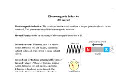
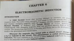
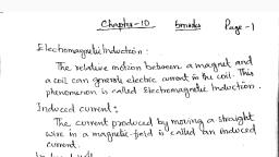
Chapter 6, , Electromagnetic Induction, , © Introduction, , e The Experiments of Faraday, , and Henry, © Magnetic Flux, , e Faraday's Law of Induction, , e Lenz's Law and, Conservation of Energy, , ® Motional Electromotive Force, , e Field Induction, , e Induced Electric Field, , Energy Consideration : A, Quantitative Study, , © Eddy Curent, , © Electromagnetic Damping, , © Self-Inductance, , © Self Inductances of Coil, , e Mutual Inductance, , © AC Generator, , © Migration of Birds, , Some Important Definitions, , e Formulae Chart, ®@ Quick Recap, , Chapter Contents, , Introduction, , Imagine a world where there is no electric lights, no trains, no, telephones and no personal computers. It was the life before the, discovery of electromagnetic induction (a Revolutionary inventionresults of experiments of scientists Michael Faraday and Joseph, Henry)., , Before the discovery of this spectacular phenomena the only source of, , electric-energy were weak electrolytic cells, capable of supplying very, weak currents that too for short durations only., , Scientist Oersted demonstrated by his experiments that electric currents, can produce (induce) magnetic field in space around it. The reverse of, results of Oersted’s experiments, was proved by the experimental, demonstration of Faraday. The conclusion of these experiments was the, electric current is generated by varying magnetic field., , When Faraday- (relative motion between magnet and wire loop, induces, a current in loop) first demonstrated before the public, he was asked, ‘What is the use of it’. His reply was ‘What is the use of a new born, baby’. Imagine how he could foresee the practical utility of this, phenomenon of EMI. In this chapter, we will study the experiments of, electromagnetic induction and their applications., , THE EXPERIMENTS OF FARADAY AND HENRY, Experiment 1, , Figure shows a coil C, connected to a galvanometer G. When the North-pole, of a bar magnet is pushed towards the coil, the pointer in the galvanometer, deflects, indicating the presence of electric current in the coil. The deflection, lasts as long as the bar magnet is in motion. The galvanometer does, not show any deflection when the magnet is held stationary. When the, , Aakash Educational Services Pvt. Ltd. - Regd. Office : Askash Tower, 8, Pusa Road, New Delhi-110005 Ph. 011-47623456
Page 2 :
146 Electromagnetic Induction Board & Competitive Exams., , , , magnet is pulled away from the coil, the galvanometer shows deflection in the opposite direction, which, indicates reversal of the current's direction., , , , Fig.: When the bar magnet is pushed towards the coil,, the pointer in the galvanometer G deflects., , Moreover, when the South-pole of the bar magnet is moved towards or away from the coil, the deflections, in the galvanometer are opposite to that observed with the North-pole for similar movements. Further, the, deflection (and hence current) is found to be larger when the magnet is pushed towards or pulled away from, the coil faster. Instead, when the bar magnet is held fixed and the coil C, is moved towards or away from, the magnet, the same effects are observed. It shows that it is the relative motion between the magnet and, the coil that is responsible for generation (induction) of electric current in the coil., , Experiment 2, , In Figure the bar magnet is replaced by a second coil C, connected to a battery. The steady current in the, coil C, produces a steady magnetic field. As coil C, is moved towards the coil C, the galvanometer shows, a deflection., , , , Fig.: Current is induced in coil C, due to, motion of the current carrying coil C,., , This indicates that electric current is induced in coil C,. When C, is moved away, the galvanometer shows, a deflection again, but this time in the opposite direction. The deflection lasts as long as coil C, is in motion., When the coil C, is held fixed and C, is moved, the same effects are observed. Again, it is the relative motion, between the coils that induces the electric current., , Experiment 3, , The above two experiments involved relative motion between a magnet and a coil and between two coils,, respectively. Through another experiment, Faraday showed that this relative motion is not an absolute, , requirement. Figure shows two coils C, and C, held stationary. Coil C, is connected to galvanometer G while, the second coil C, is connected to a battery through a tapping key K., , Cc,, , , , , , , , , , Fig.: Experimental set-up for Experiment. 3, Aakash Educational Services Pvt. Ltd. - Regd. Office : Aakash Tower, 8, Pusa Road, New Dethi-110005 Ph. 011-47623456
Page 3 :
Board & Competitive Exams. Electromagnetic Induction 147, , It is observed that the galvanometer shows a momentary deflection when the tapping key K is pressed. The, pointer in the galvanometer returns to zero immediately. If the key is held pressed continuously, there is no, deflection in the galvanometer. When the key is released, a momentary deflection is observed again, but in, the opposite direction. It is also observed that the deflection increases dramatically when an iron rod is inserted, into the coils along their axis., , , , (i) Michael Faraday (1791-1867) An English scientist who discovered electromagnetic induction, laws, of electrolysis, electric motor, electric generator, is widely regarded as the greatest experimental, scientist of nineteenth century., , (ii) Joseph Henry (1797-1878) : American experimental physicist is widely known for invention of, electromagnetic motor, efficient telegraph and discovery of self induction., , (iii) The experiments of Faraday and Henry have led directly to the development of modern day, generators and transformers. Today's civilisation owes it’s progress to a great extent to the discovery, of electromagnetic induction., , , , MAGNETIC FLUX, Like electric flux, magnetic flux is proportional to the number of magnetic field lines passing through a surface., It is denoted by o,., Mathematically 9, = B.A = BAcos0 (i), Where 4, is the magnetic flux through a plane surface of area A placed in a uniform magnetic field B. 0 is, the angle between B and A. Equation (i) can be extended to curved surfaces and non-uniform fields., , TE., , , , \A\\, , A, , Fig.: A plane of surface area A placed, in a uniform magnetic field B., If the magnetic field has different magnitudes and directions at various parts of a surface as shown in figure,, then the magnetic flux through the surface is given by, dA,, , Fig.: Magnetic field B, at the * area element. dA,, represents area vector of the /”" area element., , 69 = By.dAt + By dA2 +...= 5B, dAi, ALL, , where ‘ALL’ stands for summation over all the area element dA, comprising the surface and B is the magnetic, field at the area element., , Aakash Educational Services Pvt. Ltd. - Regd. Office : Aakash Tower, 8, Pusa Road, New Dethi-110005 Ph. 011-47623456
Page 4 :
148 Electromagnetic Induction, , , , Board & Competitive Exams., , , , (@) St unit of magnetic flux is weber (Wb). 1 Wb = 1 tesla.m?., , (ii) C.G.S. unit of magnetic flux is maxwell ( 1 maxwell = 1 gauss cm?), (iii) 1 weber = 10® maxwell (How ? Do it yourself), , (@v) Magnetic flux (like electric flux) is a scalar quantity., , (¥) Magnetic flux can also be calculated by integration method %» = Jd, = [B.A, (vi) The dimensional formula of magnetic flux is [ML2T-2A-1}, , , , , , , , it |, , @_ The normal to the plane specifies the orientation of plane., (ii) The direction of planar area vector is along its normal, (ili) For a closed surface, the area vector is in the direction of outward normal., , , , , , , , The orientation of area element and not-merely its magnitude is important in many cases. For example,, in a water stream, the amount of water flowing through a ring will naturally depend on how you hold, the ring. If you hold the ring normal to flow, maximum water will flow through it, than when you hold it, with some other orientation. Same is the case with flux also., , , , Example 1:, , Solution :, , A uniform magnetic field exists in the space B = B,i + Bj - Bk. Find the magnetic flux through, an area § if the area § is in, , () xy plane, , (il) y-2 plane, , (ili) z-x plane, , (i) Since the field is uniform, we can use formula og, = B.S, , Now when area § is in x-y plane, it means S = Sk, , Hence ¢, = (B,/ + B,j —B,k).(Sk) =-B,S, , , , , , Try Yourself 7, 14. (a) Solve the above question for part (ii)., , , , () Solve the above question for part (iii)., , , , Aakash Educational Services Pvt. Ltd. - Regd. Office : Aakash Tower, 8, Pusa Road, New Deihi-110005 Ph. 011-47623456
Page 5 :
Board & Competitive Exams. Electromagnetic Induction 149, , —_ _ —_ - Example 2: Figure shows a long straight wire carrying current | and a square conducting wire loop, of side |, at a distance ‘a’ from current wire. Both the current wire and loop are in the plane of, paper. Find the flux of magnetic field of current wire, passing through the loop., +00, , I, , , , +a—>, }<—_—x——-»idx, , boo, Solution : Since the field of current wire passing through the loop, is same in direction (normally inward) but, not uniform in magnitude. Hence we will use integration method for finding the flux., , The small flux through a thin rectangular strip of length / and width dx, is given by, , dog = Bix) dA = B,dAcos180° = 22 7x ax, 2n x, , 7, , me, , $0 = [ody = [52 ax = 22 1elog, x]-5", , , , , , __ Ho atl, = - Fsdog, ==, Try Yourself x, , 2. (a) In the example (2), the current flowing through the wire is /y = /,sinct. What is the flux, through the loop at f = 2, (©) What is the maximum flux when current hy = /gsinet?, , , , , , , , FARADAY’S LAW OF INDUCTION, , The magnitude of the induced emf in a circuit is equal to the time rate of change of magnetic flux through, the circuit. Mathematically, Instantaneous emf (i/.e., emf induced at time f = ts), , , , qd, My =~ EO., , , , ‘ e--Se__| %2-%, The average induced emf @ at [==], (for the time interval from t= fs to t= (t+ Af)s, , The negative sign indicates the direction of induced emf and hence the direction of induced current in the loop, which is in accordance with Lenz's law., , In case of a closely wound coil of N turns, change of flux associated with each turn is same. Hence total, d, induced emf @) = Wan, , Lenz’s Law : The direction of induced emf (i.e., polarity of induced emf) and hence the direction of induced, current in a closed circuit is to oppose the cause due to which they are produced. For example, if the flux, is increasing, induced emf (and hence induced current) will try to decrease the flux and vice-versa., , Aakash Educational Services Pvt. Ltd. - Regd. Office : Aakash Tower, 8, Pusa Road, New Dethi-110005 Ph. 011-47623456
 Learn better on this topic