Notes of XI Div. C & D, Physics 11. Electric Curren.pdf - Study Material
Page 1 :
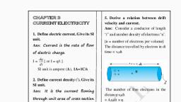
11. Electric Current through Conductor, 11.2 Electric Current, Q. Define Current .State its formula & SI unit., Current is defined as the rate of flow of electric charge., 𝐼=, , q, t, , SI unit: - Ampere (A) or C / s (Coulomb / Second), If, q = 1 Coulomb, t = 1 Second, I = 1 Ampere, Hence, One ampere is that current which is produced in the circuit, when one, coulomb of charge flows for one second through any cross section of the conductor., Q. Derive an expression for a current generated due to flow of charged particles across, a plane., , • Consider an imaginary gas of both negatively and positively charged particles moving, randomly in various directions across a plane P., • In a time interval t, let the amount of positive charge flowing in the forward direction, be q+ and the amount of negative charge flowing in the forward direction be q -., • Thus, the net charge flowing in the forward direction is, Q = q+ - q• Let I be the current varying with time., • Let Δq be the amount of net charge flowing across the plane P from time t to t + Δt, i.e,, during the time interval Δt., • Then the current is given by,, Δq, 𝐼(𝑡) = lim, Δt, Here, the current is expressed as the limit of the ratio (Δq /Δt) as Δt tends to zero.
Page 2 :
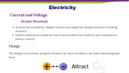
11.3 Flow of current through a conductor: Q. Explain flow of current in different conductor., • A current can be generated by positively or negatively charged particles., • In an electrolyte, both positively and negatively charged particles take part in the, conduction, • In a metal, the free electrons are responsible for conduction. These electrons flow and, generate a net current under the action of an applied electric field., • As long as steady field exists, the electrons continue to flow in the form of a steady current., • Such steady electric fields are generated by cells and batteries., 11.4 Drift Speed, Q. Explain the concept of drift velocity with neat diagrams., , • When no current flows through a copper rod, the free electrons move in random, motion. Therefore, there is no net motion of these electrons in any direction., , • If an electric field is applied along the length of the copper rod, a current is setup in the, rod. The electron inside the rod still move randomly, but tends to drift in a particular, direction., • Their direction is opposite to that of the applied electric field., • The electron under the action of the applied electric field drift speed v d., , Q. What is current density? State its SI unit.
Page 3 :
Current density at a point in a conductor is the amount of current flowing per, unit area of the conductor., Current density,, 𝐼, , 𝐽=𝐴, Where, I = Current, A = Area of cross -section, SI unit: - A/m2, Q. Prove that the current density of a metallic conductor is directly proportional to the, drift speed of electrons., • Consider a part of conducting wire with its free electrons having the drift speed vd in, the direction opposite to the electric field E., • All the electrons move with the same drift speed vd and the current I is the same, throughout the cross section (A) of the wire., • Let L be the length of the wire and n be the number of free electrons per unit volume, of the wire. Then the total number of free electrons in the length L of the conducting, wire is nAL., • The total charge in the length L is,, Q = nALe, ………… (1), Where, e = charge of electron., • Equation (1) is total charge that moves through any cross section of the wire in a, certain time interval t., 𝐿, 𝑡 = vd, ………….. (2), • Current is given by, , 𝐼=, 𝐼=, , 𝑞, 𝑡, , 𝑛𝐴𝐿𝑒, 𝐿/𝑣𝑑, , [From eq 1 & 2], , I= nAvde, Hence,, , 𝐼, , 𝑣𝑑 = 𝑛𝐴𝑒, 𝐼, , 𝑣𝑑 = 𝑛𝑒, Hence ne constant, current density of a metallic conductor is directly proportional, to the drift speed of electrons, J α vd
Page 4 :
❖ Ohms Law, Q. State and explain ohms law in electric current, Statement: As long as the physical state (Material, Dimensions, temperature etc.) of a conductor, remains the same, the electric current flowing through a given conductor is directly, proportional to the potential difference applied across it., Explanation: Let,, I = magnitude of current passing through the conductor, V = potential difference, According to ohms law,, IαV, , or V α I, , V=RI, Where, R is a constant of proportionality called resistance of the conductor., Q. Define resistance of a conductor. State its S.I Unit and dimension., Resistance of a conductor is the opposition to flow of current in the electric circuit., 𝑅=, , 𝑉, 𝐼, , SI Unit: - ohm, It is denoted by Ω, If V = 1 V, I = 1 A then R = 1 Ω, Thus, the resistance of a conductor is said to be one ohm if a current of 1 ampere, passes through it, when a P.D of one volt is maintained between its terminals., Dimension, , We know that,, , 𝑅=, , 𝑉, , 𝑉=, , 𝑊, , 𝐼, 𝑞, , 𝑊, , 𝑅 = 𝐼𝑞, = [L2M1T-2] / [A] [TA], = [L2M1T-3A-2], , Q. Define Conductance. Write down its unit and dimension.
Page 5 :
Conductance: The reciprocal of resistance is called conductance., 𝐺=, , 𝐼, 𝑉, , SI Unit: - Siemens (S) or mho (Ω-1), Dimension: - [L-2 M-1 T3 A2], ❖ Limitations of Ohms Law, Q. Define ohmic material and non-ohmic materials with examples., Ohmic Materials: • Material which obeys ohms law are called ohmic materials., • For such material I versus V graph is a straight line., Ex. Gold, Silver, Copper etc., Non ohmic materials: • Those materials which do not obeys ohms law are called non ohmic materials, • For such materials I versus V graph is a curve line, Ex. Thermistors, Semiconductors diodes etc., Q. State and explain limitations of Ohm’s law., a) Potential difference may vary non-linearly with current: -, , • According to ohms law, potential difference across a metallic conductor varies, linearly with current., • Fig shows I – V curve for good conductor. The dotted line represents ideal Ohms law, and solid line represents actual observation., • The diversion from ideal curve is due to heating effect of current. When the currents, increases, temperature of conductor increases., • As a result of this, resistance of conductor increases. Hence, slight decrease in current, due to increase in resistance is actually observed.
Page 6 :
• Metals obey Ohm’s law only if their physical condition, Such as temperature, remains, constant. Their resistance changes with temperature. Hence, their I – V characteristics, deviates from straight line if the temperature increases., b) The variation of current with potential difference may depend upon sign of the, potential difference applied., , • For semiconductor devices, electrolytes this relation is not linear, but it may depend, upon polarity of applied potential difference., • Such conductors are called non-ohmic materials. Fig shows I-V curves for, semiconductor diode., • In fig (b) it is seen that variation of current with potential difference is non-lineal so, also magnitude of variation depends upon the sign of potential difference applied, across it., • Such materials are used to rectify or amplify the current in the circuit., ❖ Resistors: Resistors are used to limit the current flowing through a particular path of a circuit., Resistors are mainly of two types, 1., 2., , Carbon resistors, Wire wound resistors, , Q. Explain the colour code system for resistors with an example., , • In colour code system resistors has 4 bands on it
Page 7 :
• In the four band resistors, the colour code of the first two band indicate two numbers, and third band often called decimal multiplier., • The fourth band separated by a space from the three value bands, indicates tolerance of, the resistor., • Following table represents the colour code of carbon resistor., , Ex. Brown Black Orange Silver = 10 × 103 +10 % = 10 KΩ + 10 %, [Note: - To remember the colour in order learn the Mnemonics: B.B.ROY of Great, Britain had Very Good Wife.], ❖ Rheostat., Q. Explain the concept of rheostat., , Rheostat
Page 8 :
• A rheostat is an adjustable resistor used in applications that require adjustment of current, or resistance in an electric circuit., • The rheostat can be used to adjust potential difference between two points in a circuit,, change the intensity of lights and control the speed of motor etc., • In hi-fi equipment, rheostats are used for volume control., ❖ Series combination of resistors, Q. Explain series combination of resistors, , • In series combination, resistors are connected in single electric path. Hence, the same, electric current flows through each resistors in a series combination., • Whereas, in series combination, the supply voltage between two resistors R1 and R2 is, divided into V1 and V2., • According to ohms law,, 𝑉1, 𝑉2, 𝑅1 =, 𝑅2 =, 𝐼, , • Total voltage, , 𝐼, , V = V1 + V2, = I (R1 + R2), V = IRs, • Thus the equivalent resistance of the series circuit is,, Rs = R1 + R2, • When a number of resistors are connected in series, the equivalent resistance is equal to, the sum of individual resistance, Rs = R1 + R2 + R3 + ………….. + Rn, , = Ʃ Ri
Page 10 :
• If n number of resistors R1,R2,R3 ……….,Rn are connected in parallel, the equivalent, resistance of the combination is given by, 1, 1, 1, 1, 1, 1, =, +, +, +, + ⋯…………….+, 𝑅𝑝 𝑅1 𝑅2 𝑅3 𝑅4, 𝑅𝑛, Thus, when a number of resistors are connected in parallel, the reciprocal of the, equivalent resistance is equal to the sum of the reciprocals of individual resistances., ❖ Specific Resistance: Q. State the factors affecting resistance of a conductor., 1. Length of conductor : Resistance of conductor increases with increase in length., 2. Area of cross section : Resistance of conductor decreases with increase in area of cross section., 3. Nature of Material : Some material like silver, gold, copper etc. have large number of free electrons, so, they have less resistance. On the other hand material like wood, rubber, etc. do not have, large number of free electrons, so they have very high resistance., , Q. Derive expression for specific resistance of a material., At a particular temperature, the resistance (R) of a conductor is, i., ii., , Directly proportional to its length (l), i. e R α l ……………… (1), Inversely proportional to its area of cross section (A), 1, 𝑅𝛼 𝐴 ………………. (2), From equations (1) and (2), 𝑙, 𝑅𝛼 𝐴, 𝑅=𝜌, , 1, 𝐴, , Where, ρ is a constant of proportionality and it is called specific resistance or, resistivity of the material of the conductor at a given temperature., iii., , Thus, specific resistance (resistivity) is given by,, 𝑅𝐴, 𝜌 = 𝑙, , SI Unit: - ohm-meter (Ω m), Dimension: - [L3M1T-3A-2]
Page 11 :
Q. What is conductivity? State its SI unit., Reciprocal of resistivity is called as conductivity of a material., 𝜎=, 1, , SI unit: -𝑜ℎ𝑚 𝑚, , 1, 𝜌, , or Siemens / metre, , ❖ Variation of Resistance with Temperature: Q. Define temperature coefficient of resistivity. Derive an expression for it., OR, Give expression for variation of resistivity and resistance with temperature., Represent graphically the temperature dependence of resistivity of copper., Ans: Temperature coefficient of resistivity:The temperature coefficient of resistivity is defined as the increase in resistance per unit, original resistance at 00 C [reference temperature] per degree rise in temperature., 𝑅−𝑅, 𝛼 = 𝑅 (𝑇−𝑇0 ), 0, , 𝛼=𝜌, , 0, , 𝜌 − 𝜌0, , 0, , Resistivity, 10-8 Ωm, , (𝑇−𝑇0 ), , Unit: - 0C-1(per degree Celsius) or K-1(per kelvin), Let,, R0 be the resistance of a conductor at 00C, Temperature ( K ), , R be the resistance when it is heated to T0C., Thus, increase in resistance = R – R0, Difference in temperature = (T – T0), It is found that,, (R – R0) α R0, , (initial resistance), , (R – R0) α (T – T0), , (temperature difference), , …………………. (1), …………………. (2), , Combining eq (1) & (2), we get, (R – R0) α R0 (T – T0), (R – R0) = α R0 (T – T0), Where,, α is a constant called temperature coefficient of resistance.
Page 12 :
𝛼=𝑅, , 𝑅 − 𝑅0, , 0, , (𝑇−𝑇0 ), , From eq (3),, Resistance of a conductor at a particular temperature is, R = R0 [1 + α (T-T0)], Resistivity of a conductor at a particular temperature is, ρ = ρ0 [1 + α (T - T0)], ❖ Superconductivity: Superconductor: Material which offer zero resistance at a certain temperature is called superconductor., Ex. Mercury at 4.2 K, Superconductivity:The phenomenon of losing resistivity completely at a particular low temperature is called, superconductivity., Critical temperature: When some metals and alloys are cooled to low temperature, resistivity suddenly becomes, zero at a particular low temperature. This temperature is called critical temperature., Application of superconductivity, • Superconducting cables are used for power distribution without loss., • Superconducting wires are used to increase speed of computer., • They are used to produce very strong magnetic field without power loss just by setting, large current in superconducting coils., , ❖ Electromotive force (e.m.f): Q. Write short note on e.m.f devices., • When charges flow through a conductor, a potential difference get established between, the two ends of the conductor., • For a steady flow of a charges, this potential difference required to be maintained across, the two ends of the conductor., • There is a device that does so by doing work on the charges, there by maintaining the, potential difference. Such a devices is called an emf device and it provides the emf E., • The charges move in the conductor due to the energy provided by the emf of the device, an amount of work done., • Power cells, batteries, Solar cells, fuel cells, and even generators, are some examples, of emf devices.
Page 13 :
Q. Define Electromotive force of a cell. Discuss its unit and dimension., Electromotive force:, The energy supplied by a cell to circulate a unit charge once round the complete, circuit is called the electromotive force (E.M.F) of the cell., If W is the energy supplied by the cell in circulating a charge q once round the, complete circuit then its electromotive force is given by,, 𝐸=, , 𝑊, 𝑞, , SI Unit: - Joule/coulomb or volt., Dimension: - [L2 M1 T-3 A-1], Q. Explain working of a circuit when connected to emf device., , • A circuit is formed with connecting an emf device and a resistor R Here the emf device, keep the positive terminal (+) at a higher electric potential then the negative terminal (-)., • The emf is represented by an arrow from the negative terminal to the positive terminal., • When the circuit is open there is no net flow of charge carriers within the device., • When connected in a circuit, the positive charge carriers move towards the positive, terminal which acts as cathode inside the emf device., • Thus, the positive charge carriers move from the region of lower potential energy, to the, region of higher potential energy, • Consider a charge dq flowing through the cross section of the circuit in time dt., • Since same amount of charge dq flows throughout the circuit, including the emf device., Hence, the device do work dW on the charge dq, so that the charge enters the negative, terminal (low potential terminal) and leaves the positive terminal (higher potential, terminal)., • Therefore, emf of the emf device is,, 𝐸=, , 𝑑𝑊, 𝑑𝑞, , • SI unit of emf: - joule/coulomb (J/C) or volt.
Page 14 :
Q. Derive an expression for current flowing through a circuit when an external resistance, is connected to a real emf device., , • If a current ( I ) flows through an emf device, there is an internal resistance (r) and the emf, (E) differs from the potential difference across its two terminals(V), V= E – Ir, ………….. (1), • The negative sign is due to the fact that the current I flows through the emf device from, the negative terminal to the positive terminal., • By Ohms law, V = IR, ………… (2), • From eq (1) & (2), IR = E – Ir, E= IR + Ir, E= I(R + r), 𝐸, , 𝐼 = 𝑅+𝑟, , • Maximum current can be drawn from the emf device, only when R = 0,, i.e, , 𝐼𝑚𝑎𝑥 =, , 𝐸, 𝑟, , ❖ Cells in series, Q. Explain the concept of series combination of cells., Ans:-, , In series combination, cells are connected in single circuit path, such that the, positive terminal of one cell is connected to the negative terminal of the next cell.
Page 15 :
The terminal voltage of battery/cell is equal to the sum of voltages of individual, cells in series., Ex :- Above figure shows two 1.5 V cells connected in series. This combination provides, total voltage,, V = 1.5V + 1.5 V, = 3 V., The equivalent emf of n number of cells in series combination is the sum of their, individual emf., ƩEi=E1+E2+E3+ ………+En, The equivalent internal resistance of n cells in a series combination is the sum of, their individual internal resistance., Ʃri = r1+r2+r3+…………+rn, , Q. State advantages of cells in series., • The cells connected in series produce a larger resultant voltage., • Cells which are damaged can be easily identified, hence can be easily replaced., , ❖ Cells in Parallel:Q. Explain combination of cells in parallel, , Consider two cells which are connected in parallel. Here, positive terminal of all, the cells are connected together and the negative terminals of all the cells are connected, together., In parallel connection, the current is divided among the branches i.e I1 and I2 as, shown in the figure.
Page 16 :
❖ Types of cells: Electrical cells can be divided, I. Primary cell, II. Secondary cell, III. Fuel cell, ❖ Primary cell, Q. Write short note on primary cell, • A primary cell cannot be charged again. It can be used only once., Ex: -Dry cells, alkaline cells., • Primary cells are low cost and can be used easily. But these are not suitable for heavy, loads., ❖ Secondary cell, Q. Write short note on secondary cell., • The secondary cells are rechargeable and can be reused., • Ex:- Lead cells fuel cell, • Lead acid battery is used widely in vehicles and other applications which require high load, currents., ❖ Fuel cell., Q. Write short note on fuel cell., • Fuel cells vehicles are electric vehicles that use fuel cells instead of lead acid batteries to, power the vehicles., • Hydrogen is used as a fuel in fuel cells., • This is important in terms of reducing emission of greenhouse gases produced by, traditional gasoline fuelled vehicles., • The hydrogen fuel cell vehicles are thus more environment friendly.
 Learn better on this topic