Notes of Class Xi, Information Technology IT_Tools_XI_802.pdf - Study Material
Page 4 :
IT Tools Level - 3, Student Handbook, Class XI, Price : `, First Edition :, © CBSE, India, Copies :, , No Part of this publication may be reproduced, stored in a retrieval system or, transmitted, in any form or by any means, electronic, mechanical photocopying,, recording or otherwise without the prior permission of the publisher., , Published by, , : The Secretary, Central Board of Secondary Education,, Shiksha Kendra, 2, Community Centre, Preet Vihar,, Delhi - 110301, , Design & Layout, BY, , : India Offset Press, A-1, Mayapuri Industrial Area, Ph-1, ND-64, , PRINTED BY, , : M/s.
Page 7 :
I, , Preface, , n an increasingly globalised world and the changing paradigm of urbanized, living the demand for Information Technology (IT) has increased manifold, throughout the world. In this ever expanding sector, it has become essential, to provide competency based Vocational Education. It is in this context that CBSE has, launched a course in Information Technology under NVEQF/NSQF from level 1 to 4., This student workbook, “IT Tools” for class XI which forms a part of vocational qualification, package for students was prepared by expertise in the field. The IT-ITeS Skill Development, Council approved by the National Skill Development Corporation (NSDC) for the IT/ITeS, Industry developed the National Occupation Standards (NOS). The National Occupation, Standards are a set of competency standards and guidelines endorsed by the representatives, of IT Industry for recognizing and assessing skills and knowledge needed to perform, effectively in the workplace., It has been a deliberate effort to keep the language used in this student handbook as simple, as possible for the benefit of the student. Necessary pictorial illustrations and tables have, been included to help the students to understand the concepts without any difficulty., Practicing professionals from the field of Information Technology (IT) comprised the team, of authors for this book. I hope this book will help the students to serve a useful resource in, this subject., The Board is grateful to the members of the Committee of Course for their advice, guidance, and total commitment towards development of this course. We are indeed indebted to, these academic advisors who have lent us the benefit of their rich and insightful experience., I would like to appreciate Vocational Education Cell, CBSE for coordinating and successfully, completing the work., Comments and suggestions are welcome for further improvement of the book., , Chairman, CBSE, , v
Page 9 :
Contents, Unit–1:, , Unit–2:, , Unit–3:, , Unit–4:, , Unit–5:, , Unit–6:, , Computer Organization & OS : User Perspective, , 1, , Chapter–1: Computer Organization & OS: User Perspective, , 2, , Networking and Internet, , 15, , Chapter–2: Networking and Internet, , 16, , Office Automation Tools, , 45, , Chapter–3: Word Processing, , 46, , Chapter–4: Spreadsheet (OpenOffice Calc), , 68, , Chapter–5: Presentation, , 130, , Multimedia Design, , 149, , Chapter–6: Multimedia Design : (Open Source Design Tools), , 150, , Troubleshooting - Hardware, Software and Networking, , 285, , Chapter–7: Troubleshooting - Hardware, Software and Networking, , 286, , Work Integrated Learning IT - ISM, , 315, , Chapter–8: Work Integrated Learning IT-ISm, , 316, , vii
Page 10 :
viii
Page 11 :
Paper - I, Total Marks: - 100, (Knowledge- 50: Practical-50), Unit Code, ITDC-301, , Unit Title, Computer Organization & OS: User Perspective, , Total Hours, 15, , • Understanding of Hardware, •, ITDC-302, , Basics of Operating System, , Networking and Internet, , 10, , • Network Safety Concerns, • Network Security Tools and Services, • Cyber Security, • Safe practices on Social Networking, • Email Messaging, • Digital Literacy, ITDC-303, , Office Automation Tools:, , 40, , • Spreadsheet, , ITDC-304, , •, , Word Processing, , •, , Presentation, , Multi Media Design: (Open Source Design Tools), , 35, , • Interface and Drawing Tools in GIMP, • Applying Filters, • Creating and Handling Multiple Layers, • Using Stamping and Smudging Tools, • Importing Pictures, , ix
Page 12 :
Unit Code, ITDC-305, , Unit Title, Troubleshooting: Hardware, Software and Networking, , Total Hours, 10, , • Commonly Encountered Problems, •, , ITDC-306, , (Monitor: No display, KB/Mouse not responding,, monitor giving beeps, printer not responding, check for, virus, Delete temporary files if system is slow, adjust, mouse speed), , Work Integrated Learning IT - ISM, , 14, , • Identification of Work Areas, •, , Work Experience, 124, , x
Page 13 :
Unit - 1, , Unit - 1, , IT Tools, , Unit - 1, , Computer Organization, & OS : User Perspective, , 1
Page 14 :
Unit - 1, , Chapter, , 1, , Computer Organization & OS: User Perspective, u, , Understanding of Hardware, , u, , Basics of Operating System, This unit aims at making the students aware of the fundamental concepts of a computer, system. The key concepts that will be addressed are, u, , Hardware, , u, , Software, , u, , Functionality of a computer, , u, , Operating system, , u, , Types of operating system, , 1.1, , Fundamentals, , In the technological era that we live in, we use computer day in and day out. It is therefore, but natural that we be aware of what constitutes this machine which solves so many of our, technological and apparently not so technological problems., In common terminology, we talk of a computer as a machine which executes a set of, instructions provided by the user to produce the desired output. As per Oxford Dictonary,, a computer is defined as “an electronic device which is capable of receiving information, (data) in a particular form and of performing a sequence of operations in accordance with, a predetermined but variable set of procedural instructions (program) to produce a result in, the form of information or signals.”, The language understood by computers is what is termed as binary language, a language, formulated as sequences of 0s and 1s. However, the instructions which are provided by, the user are in the form of English like language. These therefore need to be converted to, , 2
Page 15 :
The term hardware refers to the tangible components of a computer that we can touch and, feel like the keyboard, mouse, monitor. However, the term software refers to the intangible, components like word processor, operating system, and data. The data and/or instructions, given by the user to the machine are termed as Input and the result generated by the machine, for use by humans is termed as Output., Before we look in detail these concepts let us understand the characteristics of computer that, make it so special!!, , 1.2, u, , u, , u, , u, , IT Tools, , Characteristics of a computer, Speed: A remarkable quality of computers is their ability to process data and, instructions at a very high speed. A typical high-speed computer can perform about, 3-4 mips (million instructions per second). Note that this is different from the speed, with which information can be sent to and from a computer, which is normally, measured in baud., Versatility: is the ability of a computer to do a variety of jobs with ease. One moment, you can type a letter using any of the available word processing packages, and the, other moment you can use the same machine to do calculations yielding the salaries, of employees of an organization., Accuracy: Not only does the machine performs varied jobs with high speed, but, also does them with high precision and accuracy. Note that the errors that one may, see in output produced by the computer is not because of the machine, but because, of either wrong entry of data or wrong instructions given to compute. In computer, terminology, this phenomena is often referred to as GIGO (Garbage In Garbage Out), Diligence: Another noteworthy feature of computer is its ability to perform the same, task repeatedly over and over again without getting bored! For example a task of, adding 1000 numbers repeatedly for 10000 times if given to a computer, it would be, able to do the task with the same accuracy every time without complaining that it is, being asked to do this job over and over again!!!, , 3, , Unit - 1, , machine readable format (the binary format i.e. 0 and 1) and then processed by the machine., Similarly, the result of the processing is also in a format understandable only to the machine., This also needs to be converted back into a format which humans can understand. All, this is achieved by an effective co-ordination of the components of the computer; broadly, categorized as hardware and the software.
Page 16 :
Memory: One of the notable features of a computer is its memory. However, the, computer’s main memory is volatile, i.e., it is lost when we switch off the computer., Therefore, computers are provided another form of memory that does not fade away, when it is switched off. It is called secondary memory and is available in the form of, floppy disks, pen drives, portable hard disks., , Unit - 1, , u, , Storage: Huge amount of data and information can be stored in a computer for, future retrieval. The human memory is limited and fades away with time, which is, not true for a computer., , u, , Intelligence: In the early days, although computers possessed striking characteristics, yet a prominent drawback was that they are merely dumb machines which were, programmed to perform certain tasks. With the advent of artificial intelligence, techniques, we now have machines which can drive a car without a human driver or, play chess against the best players., , u, , Thus to summarize, this electronic device is capable of storing, processing huge amount of, data and/or instructions with accuracy, diligence and high speed in an untiring manner., Having seen the characteristics of a computer, now let us understand the way a computer, works., , 1.3, , Block diagram of a computer, , Figure 1.1: Block diagram of a computer, , 4
Page 17 :
1., , Accepts Input: To initiate the process, the computer needs to be told of the problem, to be solved. For this purpose, a set of instructions and data is provided through the, input devices such as keyboard and mouse. A set of instructions provided to the, computer for doing a task is called a program., , 2., , Storage: The inputs received in the above step are stored in the computer memory,, called random access memory (RAM). It is also called main memory, primary, memory, or working memory of the machine. Storage plays a very important role., All the inputs, the intermediate results of computation carried out, and the final, result are stored in the memory of the computer. The computer also has another form, of memory called secondary memory. The programs and data not currently required, are stored in secondary memory. It comes in the forms such as a hard disk, pen drive,, and CDROM. When required, for processing, these can be retrieved and transferred, to the main memory of the computer,, , 3., , Control: The manner in which the program is to be executed is managed by the, control unit of the computer. This entails deciding the address from which the, instructions to be executed is to be picked up, the memory location where the data or, intermediate result is to be stored, etc., , 4., , Processing: The inputs provided by the user are processed by the central processing, unit as per the specified instructions. The result of the processing is then either, directed to the output devices or to a memory location for storage., , 5., , Provides Output: The outcome of the computation carried out by the computer is, often directed to the display device such as the monitor or printer. Other forms of, devices are not uncommon, for example, the computer may output music or video., , We have seen above that the input unit receives data, which is stored in the main memory,, from where it gets transferred to the Central Processing Unit and subsequently to the output, device. The Central Processing Unit comprises of two modules; the Arithmetic Logic Unit, and the Control Unit., Arithmetic Logic Unit (ALU) is responsible for processing of data. It retrieves the data from the, storage unit and performs the arithmetic calculations and/or comparisons on them and the, processed data is then sent back to the storage., , IT Tools, , 5, , Unit - 1, , To understand the functionality of a computer we need to understand the processes of task, execution. Following are the steps to be performed
Page 18 :
Unit - 1, , Control Unit is responsible for coordination between the different units of a computer. For, example, it coordinates with the peripheral devices to accept the input or display the output., It also coordinates between memory and ALU by issuing timely signals., As mentioned above, the storage unit comprises of the primary storage and the secondary storage., Primary Storage: The main memory in the computer, also called primary storage comprises, of RAM. This storage is relatively fast and expensive as compared to the secondary storage., As seen in Figure 1.1 primary memory is directly connected to the CPU., Secondary Storage: The memory which is external to the computer system forms the, secondary storage, for example, the magnetic tapes, compact disks, pen drives are all example, of the secondary storage. These are not directly connected to the CPU, , 1.4, , Inside the Computer, , There are various types of computers in the market these days, desktop personal computer, – popularly known as PC, laptop (also called notebook) – a small computer that can easily, put on your lap, tablet – a light computer of the size of a handbook, often used for working, on the Internet., If we look at a personal computer, from outside, it comprises of a box (sometimes called CPU), that contains CPU and hard disks, keyboard, mouse, monitor and speakers. The keyboard,, mouse, speakers constitute the peripherals. The major functionality is in the processing unit., Let’s now peep into the chassis of a processor!, , Figure 1.2: A peep in the computer, , 6
Page 19 :
1.4.1 Components, Motherboard: This is the main circuit board which holds together various components, like CPU, memory, connectors for the hard drive and optical drives, expansion cards, to control the video and audio, and connections in the form of various ports (such as, USB ports). It provides a connection to every component of the computer., , Figure 1.3: Motherboard, u, , u, , CPU: The motherboard houses the main processor or the CPU (Central Processing, Unit). CPU executes the user instruction and coordinates amongst all other units of, the computer. Thus, it is primarily responsible for the performance of the machine., There are a variety of processors in the market categorized on the basis of their, speed, technology (dual-core, quad-core, octa-core) and their manufacturers (Intel, and AMD to name just two). Speed of a processor usually measured in megahertz, (MHz) – millions of instructions per second; and gigahertz (GHz) – billions of, instructions per second, is indicative of its power., Power Supply Unit: This component of the computer is the one which converts the, alternate current power supply being received by homes or offices to the low voltage, direct current required by the machine., , Figure 1.4: Power Supply Unit, , IT Tools, , 7, , Unit - 1, , u
Page 20 :
Hard disk: It is the secondary storage device for storing the data. The program, which is to be executed is first stored in the hard disk from where it is transferred to, RAM. On completion of work, the program is again saved on the hard disk., , Unit - 1, , u, , Figure 1.5: Two sided view of a sealed hard disk unit, , It is usually characterized by the performance and its capacity. Memory capacity is, specified in terms of bytes. These days the capacity of a hard disk is expressed in terms of, Gigabytes, Terabytes., Let’s look into the hierarchy of the terms used to specify the capacity, Everything in computer is stored in terms of Bits (Binary Digits) i.e 0’s and 1’s, 1 nibble = 4 bits, 1 byte = 8 bits, 1024 bytes = 1 Kilobyte (KB), 1024 KB = 1 Megabyte (MB), 1024 MB = 1 Gigabyte (GB), 1024 GB = 1 Terabyte (TB), 1024 TB = 1 Petabyte (PB), And this is how a Compact Disk drive looks like, , 8
Page 21 :
Unit - 1, , Figure 1.6: A Compact Disk Drive, u, , Random Access Memory (RAM): This memory storage plays an important role, in the functioning of a computer system. Every time you start up the computer, the, operating system (the system software that manages the device’s interaction with the, peripherals and the internal resources) is loaded in the RAM. The program that needs, to be executed at any point of time also needs to be brought in the RAM. These days, the PCs have around 8-32 GB RAM. More the RAM, more will be the space for the, programs leading to faster execution. Of course, everything in computers is subject, to some limits., , All these components need to work in co-ordination and this is accomplished by the, operating system. It initializes the system for our use. In the next section, we study the basics, of operating systems., , 1.5, , Operating system, , A computer needs to communicate with both the hardware and software; to do this; it, utilizes the services of an Operating system. Examples of some popular operating system, are Windows, Linux, Unix, MS-DOS, SOLARIS, MAC OS. The operating system acts, as an interface between the users of the system and hardware of the system. It also acts, like a government which lays down policies for efficient utilization of the resources and, provides for effective co-ordination amongst the various components of a computer. Every, computer system whether it is an independent system like a desktop or a cell phone must, have an operating system for performing the core functionalities like accepting input from, various input devices, directing the output to the display, managing the files and directories,, communicating with hardware, and installing /uninstalling of peripheral devices., , IT Tools, , 9
Page 22 :
Unit - 1, , Figure 1.7: Operating system an interface, , 1.5.1 Functions of an Operating system, The prime functions of an operating system can be broadly categorized as:, u, , Providing for communication between User and computer, , u, , Resource management, p, , Process management, , p, , File management, , p, , Memory management, , Figure 1.8 presents the various functions of an operating system., , Figure 1.8: Various tasks of operating system, , 10
Page 23 :
Resource Management: The working of a computer system is predominantly dependent on, how its resources are being managed. The resources that we talk of here; are the memory of, the computer, the CPU time, files,secondary storage, input/output devices etc. The operating, system handles the allocation of all such resources, the priority in which these are allotted to, the various processes to get an optimum performance from the system. We discuss here the, prime resource management., Process Management: A process is a program currently executing in the memory or waiting, for the CPU. In a computer there are multiple processes in the system. The OS manages,, controls, schedules all the processes being executed in the computer. It decides which process, gets the processor and for how long., Memory Management: For a process to be executed, it has to be loaded in the working, memory that is the RAM (Random Access Memory). The memory management component, of an operating system allocates memory to the processes in a dynamic manner that is, allocated on demand and released when not needed., File Management: Operating system takes care of all the files and folders (directories), maintained on the computer disk. The basic tasks that a user needs to perform on files are, creation, renaming, deletion, copying or moving of a file or folder. All the files stored in a, computer system can be located through the file system. Two main types of file system are, File Allocation table (FAT) or New Technology File system (NTFS)., 1.5.2 Types of Operating system, Operating systems can be classified in different ways; depending on various parameters., l, , Single-tasking and Multi-tasking, , Single tasking such operating systems allow execution of only a single program at any given, instant, Mutli-tasking As the name suggests, multi-tasking operating system can execute more than one, programs simultaneously. The processor time, in this case, is divided amongst various processes., , IT Tools, , 11, , Unit - 1, , Communication Manager: Manages the communication needs of the system, be it, communicating with the peripheral devices or the internet, are addressed by the operating, system. Each of the peripheral devices like printer, mouse have unique characteristics and, the computer needs to know these unique properties, to interact with them. For this, the, operating system uses special programs called drivers which enable recognition of these, devices and their properties.
Page 24 :
Single user and Multi-user, , Unit - 1, , l, , Single-user operating systems allow only one user to use the system. The desktop systems, can be classified as typical single user systems, Multi-user operating systems allow many users to access the system by maintaining an, account of all the registered users., Real-time Operating System, , l, , Operating systems which ensure that the response time is fixed are categorized as real-time, operating systems. They are intended for applications where data needs to be processed, quickly, without any significant delays. For example, an antiaircraft missile system must fire, as soon as it receives signal from the enemy aircraft, before it leaves the bomb and flies away., Batch Processing Systems, , l, , In a batch processing systems, similar jobs are clubbed together and submitted as a block, to the processor for execution. User intervention is minimal in such systems. The jobs are, picked up one by one and executed., , Exercises, Fill in the blanks, 1. The unit used to measure the performance of a computer is ..................... ., 2. Two main types of File system are ..................... and ..................... ., 3., , 1 petabyte = ..................... bytes, , Short Answer questions, 1. List the various functions of an operating system., 2. Compare batch processing systems and multiprogramming systems., 3., , Why do devices need device drivers?, , Hands-on Exercise, Check up the configuration of your personal computer and find out the following, a) The processor type, make, speed, b) Amount of RAM, , 12
Page 25 :
c) Hard disk capacity, , Do this for few more machines and tabulate the data. Analyze how each of them influences, the performance of the computer system, Identify the operating system installed on your home computer. Classify it on the basis of operating, systems studied in the chapter., Identify two instances of hard real-time and soft real time systems., , IT Tools, , 13, , Unit - 1, , d) Number of ports
Page 26 :
14
Page 27 :
Unit - 2, , Unit - 2, , Networking and, Internet
Page 28 :
Chapter, , 2, , Unit - 2, , Networking and Internet, In the beginning of civilization humans communicated via means such as oral, gestures,, and touch. Knowledge transcended from one generation to another largely by way of oral, traditions, and later on by inscriptions on stone and metal until early forms of paper were, developed. However, education remained largely confined to the elite until the invention of, printing press by Johannes Gutenberg, around 1440. It lead to dissemination of information, through newspapers and books and provided a new and versatile method of communication, of information. This was followed by the era of telegraph and telephone marking nineteenth, century. Twentieth century saw the development of commercially viable radio and television, which became instrumental in dissemination of information and entertainment. ARPANET, that began with a network connecting computers in a few organizations in early sixties paved, the way for Internet in early eighties that revolutionized not only the exchange of information, amongst individuals and organizations, but also the way organizations do business, and the, people educate, entertain, and organize themselves. Social networking, instant messaging,, voice calls (through VOIP), media are influencing the definition of Internet being used., , 2.1, , Evolution of Networks and Internet, , In 1876 Bell came forward with the concept of communication through telephone lines, leading to development of Public Switched Telephone Network (PSTN) in 1877. It opened, the new frontiers allowing several homes to connect through telephone lines. From that, time, communication was mainly through telephone lines. In late 1950s, all the military, communications started using telephone networks setting up dedicated connection between, the two parties. This dedicated connection made use of technology called circuit switching., The connection comprised of several intermediary lines and switching offices enroute. They, were vulnerable to danger of damage to the switching offices which may disrupt the entire, network. At the peak of cold war, US Department of Defense (DoD) realized the need to, establish fault-tolerant network that would not fail at the time of nuclear war and could, survive a single point failure in the network. Paul Baran along with Donald Davies and, , 16
Page 29 :
Len Kleinrock came forward with the idea of digital packet switching in which the message, to be transmitted is divided into small chunks called packet. Unlike circuit switching in, which resources are reserved along the dedicated path of communication, packet switching, is based on link sharing., , Source: http://personalpages.manchester.ac.uk/staff/m.dodge/cybergeography/atlas/arpanet4.gif, Figure 2.1: ARPANET, , Need for communication between various heterogeneous networks led to the development, of TCP/IP (Transmission Control Protocol/Internet Protocol) in 1970. Along with several, smaller networks, another large network called NSFNET was developed in 1984 by NSF,, U.S. National Science Foundation for research and education purpose. When ARPANET, and NSFNET were interconnected, the network growth increased tremendously. TCP/, IP protocol (rules for communication) acted as a glue to connect various heterogeneous, networks together into a single network. This wide network is an Internet (network of, networks)., , IT Tools Level - 3, , 17, , Unit - 2, , US Department of Defense realized the need to connect geographically separated research, computers together to form a network. This led to the development of Advanced Research, Projects Agency Network (ARPANET) in 1969 (Figure 2.1). ARPANET made use of, technology called digital packet switching. Initially its use was restricted to non-commercial, purpose such as military and research. Subsequently, its use extended to education by, supporting various educational institutes.
Page 30 :
Unit - 2, , With the advent of Internet, the whole world got connected on a global level. In mid 1990s,, the number of nodes connected through Internet began to grow exponentially. Several, government and private organizations, collectively called Internet Service Providers (ISPs), joined hands to provide connectivity for Internet. Internet made it possible to exchange, information and communicate with remote nodes. There are several applications of Internet, such as e-mail, file transfer, remote login, and World Wide Web (WWW)., , 2.2, , Computer Networks, , Nodes or stations are electronic devices such as computers, printers, Fax machines, and, telephones which communicate with each other by sending and receiving data/message., Figure 2.2 depicts a one-way simple communication system that comprises the following, components:, u Sender:, , The node that is responsible for sending the data., , u Receiver:, , The node that is responsible for receiving the data., , Message: Message is the information or meaningful data that is being communicated, in a structured form., , u, , u Channel:, , Channel is the communication medium through which message is, transmitted., Channel, Message, , Sender, , Receiver, , Figure 2.2: One-way Communication System, , A collection of interconnected nodes which communicate by means of some channel, form computer network. The communication taking place in a computer network can be, categorized as simplex, half-duplex, and full-duplex. In simplex mode, information can be, transferred only in one direction. This mode is termed unidirectional. In computer networks,, the data transmitted using many fiber optics and satellites is simplex in nature. Half-duplex, mode is a bidirectional communication between the two nodes, however, only one node at a, time can transmit the data. This mode is generally used for transferring files between nodes, in a low-bandwidth setting. In full-duplex mode, both communicating parties can send and, , 18
Page 31 :
receive at the same time. The interactive applications use this mode of communication, thus, speeding up the data transfer. NIC (Network Interface Card) on the systems for networking, supports full-duplex mode., Computer networks can be used as means of resource sharing and communication., u, , Computer System A, , Computer System B, , Computer System C, , Printer, , Figure 2.3: Computer Network, u, , Communication: Connecting computers through network facilitates exchange of, information amongst the nodes in the network. For example, any of the computer, systems in Figure 3 may send data to any of the three computer systems or the printer,, as it is connected to every node in the network., , Creation of a network requires various network devices such as modems, routers, switches,, and bridges, each of which plays a specific role in the network. Networks differ on the basis, of transmission media used, arrangement of nodes in the network, their geographical span,, and their purpose., , IT Tools Level - 3, , 19, , Unit - 2, , Resource Sharing: Connecting computers through networking allows us to, share hardware and software resources. Examples of hardware resources include, peripherals (for example, printers and scanners), CPU, and memory. Examples, of software resources include system and application software, and files that, may include text, audio, and video content. Note that in the network shown in, Figure 2.3, all the three computer systems are connected with each other and to the, printer through the network facilitating sharing of printers.
Page 32 :
2.2.1 Transmission Medium, , Unit - 2, , A transmission medium refers to the channel of transmission through which data can be, transmitted from one node to another in the form of signal. A signal encodes the data in a, form suitable for transmission on the medium. A medium is characterized by its bandwidth, defining the information carrying capacity of the medium. A transmission medium may, belong to one of the following two categories:, Guided Medium: The term refers to physical conductor such as twisted pair, coaxial, cable, and fiber optics. In twisted pair and coaxial cable, the signal travels as voltage, and current signal whereas in optical fibre, the signal is in the form of light., , u, , Unguided Medium: The unguided medium uses electro-magnetic waves that do not, require a physical conductor. Examples of unguided medium include infrared, radio,, and microwave., , u, , 2.2.2 Topology, The arrangement (also called layout) of nodes in a network is called network topology., There are broadly two types of topologies – broadcast and point to point. In broadcast, topology, all nodes share the same physical link. When one node transmits, all nodes, receive. Collision may occur when more than one node simultaneously transmits, and there, is collision resolution mechanism for handling it. Broadcast topologies are mainly bus and, ring. In point to point topology, every pair of nodes has a dedicated link. Popular point to, point topologies are star and mesh., Bus Topology, , u, , In bus topology, there is a long cable, called backbone cable (or simply backbone), that, connects various nodes through connector called tap as shown in Figure 2.4. In this, a, message sent by one is received by all devices connected to backbone cable. This topology, requires less cabling and is easy to install and extend the network laid using it. However,, fault detection and isolation is difficult., , Terminator, Tap, Tap, , Tap, , Figure 2.4: Bus Topology, , 20, , Tap, , Cable
Page 33 :
u, , Ring Topology, , Device A, , Device B, , Device C, , Device E, , Device D, , Figure 2.5: Ring Topology, u, , Star Topology, , In star topology, all the devices are connected to the central controller called hub as shown, in Figure 2.6. Communication between any two devices takes place through the hub, responsible for relaying messages. Star network can be easily installed and configured. Also,, fault detection and isolation is easy. However, it requires more cabling as compared to bus, and ring topology. Also, hub failure will lead to network failure., , IT Tools Level - 3, , 21, , Unit - 2, , In ring topology, all the devices are attached through a cable in the form of ring as shown, in Figure 2.5. The message to be communicated is transmitted in one direction, thereby,, relaying the message to the intended recipient. Addition and deletion of devices, and fault, detection and isolation is easy. However, the topology suffers from the limitation of single, point failure leading to disruption of entire network. Sending a message from one node to, another node may take more time (four steps while sending message from device A to E)
Page 34 :
Unit - 2, , HUB, , Figure 2.6: Star Topology, , Mesh Topology, , u, , In mesh topology, every node is connected with every other node in the network as shown, in Figure 2.7. Because of dedicated point to point connection between every possible pair of, nodes, the topology provides secure data transfer without any traffic problem. It requires a, large number of connections establish the topology. This leads to difficulty in installation as, the number of nodes grow as the network grows., , Figure 2.7: Mesh Topology, , Tree Topology, , u, , Tree topology is a hybrid topology using combination of star and bus topology. Backbone, cable in a bus topology acts like the stem of the tree, and star networks (and even individual, , 22
Page 35 :
nodes) are connected to the main backbone cable like the branches of tree as shown in, Figure 2.8. Damage to a segment of a network laid using tree topology will not affect other, segments. Installation and configuration is difficult as compared to other topologies. Also, if, the backbone cable is damaged, the entire network communication is disrupted., S, , R, , H3, , B, , C, , Unit - 2, , A, Hub, , Q, , H1, Hub, , P, , O, , D, , E, , N, M, , F, G, H4, , L, , Hub, H2, , H, , Backbone, Cable, , Hub, , I, , K, , J, , Figure 2.8: Tree Topology, , 2.2.3 Network Types, On the basis of geographical span, network can be broadly categorized as LAN, MAN, and, WAN., u, , LAN stands for Local Area Network. Local Area networks are private networks, and can span a radius of up to 1 Km. They are generally established within a building, or campus shown in Figure 2.9. LANs operate at a speed in the range 10 Mbps to, 1 Gbps., , IT Tools Level - 3, , 23
Page 36 :
Unit - 2, , Headphone, (a) LAN within a building, , (b) LAN within a Campus, , Figure 2.9: LAN, , MAN stands for Metropolitan Area Network. It may be owned by a single organization, or by many individuals or organizations. These networks are used to establish link, within a city, and span an area of radius up to 50 Km. MANs facilitate sharing of, resources by connecting various local area networks (Figure 2.10). For example, a, cable television network within a city., , u, , LAN 1, , MAN, , LAN 2, LAN 3, , Figure 2.10: Metropolitan Area Network MAN, , WAN stands for Wide Area Network. Typically a WAN spans a segment of about, 1000 Km. They are used for long distance communication and are well suited for, connecting remote areas. They establish link within a country or continent. A WAN, may be owned and managed by several organizations. It connects various local and, metropolitan area networks as shown in Figure 2.11., , u, , 24
Page 37 :
MA, N, , MAN, , MAN, , Unit - 2, , N, , LA, , Figure 2.11: WAN, , 2.2.4 Internet Working Devices, Creation of a network requires various network devices, each of which plays a specific role, in the network., u, , Repeater, , With increase in distance, a signal may become weak and distorted. A repeater is used to, restore the input signal to its original form, so that it can travel a larger distance. Thus, it, is placed between two cable segments as shown in Figure 2.12. It is also known as digital, regenerator which reshapes and amplifies the digital signal., Repeater, , Repeater, , Figure 2.12: Repeater, , IT Tools Level - 3, , 25
Page 38 :
Hub, , u, , Unit - 2, , Unlike a repeater which connects two cables, a hub connects several lines, also called, cable, segments. A hub comprises several input/output (I/O) ports, each of which connects to a, single cable as shown in Figure 2.13. Data arriving on an incoming line is output to all lines, except the line on which the hub receives the data., , HUB, , Figure 2.13: Hub, , Bridge, , u, , A bridge is a multiport device used for connecting two or more local area networks (LAN),, possibly operating at different speeds as shown in Figure 2.14. Thus, a bridge may be used, to produce bigger LAN by combining smaller LANs. A bridge enables devices on one LAN, segment to communicate with the devices on another LAN segment. Unlike hubs, they, are intelligent devices which exercise discretion while forwarding data to the outgoing line, leading to destination., , Figure 2.14: Bridge, , 26
Page 39 :
u, , Switch, , Unlike bridges which connect two or more LAN segments, switches are used to connect, individual nodes in the network with each other. Each node within network is connected to, a unique port in the switch as shown in Figure 2.15. On receiving the incoming data frame,, it forwards it to only single line connecting to the destination node. All the nodes connected, through switch forms only one LAN., , Unit - 2, , Figure 2.15: Switch, u, , Router, , Routers are used for connecting various networks (LAN or WAN) with each other as shown, in Figure 2.16. A router transmits data from incoming network to another network. A router, maintains a routing table of various networks. Based on the destination address, the router, determines to which network the incoming packet should be transmitted., , Figure 2.16: Router, , IT Tools Level - 3, , 27
Page 40 :
Gateway, , u, , Unit - 2, , A gateway connects networks based on different protocol technologies to communicate with, each other. Data coming from one network operating on one protocol is converted according, to the protocol of outgoing network, and then forwarded. Thus a gateway may be thought of, as a router equipped with software for protocol conversion., , 2.3, , Internet, , A wide network of networks i.e. interconnection of WANS form the global Internet. It, is neither owned by any single individual nor by any single organization. It has made it, possible to exchange information and communicate with remote nodes. One can access the, Internet using several means such as leased line, dial-up access, and wireless connectivity., The machines on the Internet are known as hosts. The machine that initiates a request is, called client and the machine that processes a client request is called server., Communication between any two machines on the Internet is governed by the universal, TCP/IP protocol – glue that holds entire Internet together. A network protocol defines, the rules and conventions of communication that must be followed when two devices, interact with each other. It specifies what should be communicated, and how and when, communication should take place., There are several applications of Internet such as e-mail, file transfer, remote login, and, World Wide Web (WWW) listed below:, Electronic Mail (E-Mail), , u, , An email may be a written text and may include multimedia attachment consisting of text,, audio, image, or video. Sender of the e-mail may send it to one or more intended recipients., Sending and receiving of mails can take place through web based e-mail application also, called webmail application, (such as, Gmail, Windows Live Hotmail, and Yahoo), or a, desktop based e-mail applications (such as, Microsoft outlook, Thunderbird, mail application, on mobile phone). Transferring mail over the Internet is governed by a set of rules known, as email protocols such as SMTP (Simple Mail Transfer Protocol) and POP3 (Post Office, Protocol)., File Transfer, , u, , Transferring files from one machine to another through a TCP based network is done using, FTP (File Transfer Protocol). File Transfer Protocol is based on client server architecture., Using FTP, local host (client) can download or upload files to and from remote host (server)., , 28
Page 41 :
u, , Remote Login (TELNET), , u, , World Wide Web (WWW), , World Wide Web (WWW), commonly known as web, is a repository of information on, machines spread all over the Internet and linked to each other. The information is organized, in the form of documents called web pages. A web page may contain text, images, audio,, videos, and information for linking the web pages in the form of hyperlinks. WWW uses, distributed client server architecture based on HTTP (Hyper Text Transfer Protocol). The, client request is relayed through Internet to the appropriate server, which sends back the reply, through Internet to the host system. A simplified view of how a request for information on, WWW may be handled on WWW is shown in Figure 2.17., , Figure 2.17: WWW and Internet, , 2.4, , TCP/IP Model, , The TCP/IP (Transmission Control Protocol/Internet Protocol) is often called the glue, which holds Internet and WWW (collection of servers where information is stored), together. When we are dealing with the Internet, we are essentially dealing with the TCP/, IP model. The simple task of sending the data from one place to another through network, , IT Tools Level - 3, , 29, , Unit - 2, , TELNET stands for TErminaL NETwork. It is a client server based application that allows, the user working on one system to access a remote system. For initiating remote login, the, user (client) should specify the address of remote system, and should authenticate himself/, herself using username and password mechanism. On successful login, the client can access, the remote system. TELNET service is often used for accessing data on the remote host, or, executing on the server the applications installed on it (server).
Page 42 :
requires several sub-tasks such as specifying sender and receiver’s network and physical, address, dividing the message into smaller fragments so that they can be easily transmitted, over Internet, taking appropriate measures for error and flow control, and taking necessary, action on receiving the message. These sub-tasks or functions are performed by different, layers of TCP/IP model as shown in Figure 2.18., , Unit - 2, , Application Layer, Transport Layer, Internet Layer, Link Layer, Figure 2.18: TCP/IP Model, , As shown above, TCP/IP model comprises of four layers, Application layer, Transport layer,, Internet layer, and Link layer. On each layer, several protocols operate which define rules for, transmission of data., Data/message is created at the sender’s end at Application layer. At the receiving end, it is examined and processed (possibly displayed) at Application layer. This layer is also, responsible for enveloping the message to be sent with the header. Several protocols such as, HTTP, SMTP, POP3, and TELNET (remote login) operate on this layer., Application layer passes the message to the Transport layer which appends the information, about the source and destination ports of the processes at two ends. At the ends, the ports, process the message. Mainly two end-to end protocols operate at this layer, namely TCP, and UDP. TCP (Transmission Control Protocol) is a reliable connection-oriented protocol, needed when timely and error free delivery of data is important. UDP (User Datagram, Protocol) is an unreliable connectionless protocol needed in a scenario such as exchange, of short messages and client server request-reply messages, where immediate response is, more important rather than assured delivery. Also it may be used as a transport protocol, for streaming video because the occasional loss of a packet is acceptable. Further, transport, layer divides the message into a number of fragments, called segments, depending upon, the maximum transmission size permitted. In TCP, each segment will carry the sequence, number denoting its relative position in the message, so that, the message can be assembled, at the receiver end by the transport layer at recipient’s end., Transport layer hands over the segments to the Internet layer which adds source and, destination machine network address (also termed IP address). Internet layer is mainly, , 30
Page 43 :
Link layer is also called Host to Internet layer. This layer is responsible for adding the header, containing sender and receiver physical address to the packet received from Internet layer., The resulting message is called frame. It may be noted that recipient’s physical address, corresponds to the physical address of the next host on the network to which message is to, be relayed, and not (necessarily) the physical address of the destination machine., Suppose host 1 wishes to send a message Hello to host 2. Diagram in Figure 2.19 illustrates, how layer by layer message is processed at the host 1 and host 2., Message, , Application, Layer, , Port, No., Host 1, , Transport, Layer, , IP, address, Host1, , Internet, Layer, , IP, address, Host 2, , Port, No., Host 2, Segment, , Port, No., Host 1, , Message, , Port, No., Host 1, , Message, , Port, No., Host 2, , Internet, , Message, , IP, address, Host1, , IP, address, Host 2, , Packet, , Link, Layer, , MAC, address, Sender1, , MAC, address, Receiver1, , IP, address, Host1, , IP, address, Host 2, , Port, No., Host 2, Segment, , Port, No., Host 1, , Application, Layer, , Message, , Transport, Layer, , Port, No., Host 2, , Message, , Packet, , Port, No., Host 1, , Port, No., Host 2, , Frame, , Messag, e, , MAC, address, Sender2, , MAC, address, Receiver2, , IP, address, Host1, , IP, address, Host 2, , Port, No., Host 1, , Port, No., Host 2, , Messag, e, , Internet, Layer, , Link, Layer, , Frame, , TCP/IP, stack of, Host 2, , TCP/IP, stack of, Host 1, , Figure 2.19: Message transfer illustrated through TCP/IP Model, , 2.5, , Network Safety Concerns, , With increase in use of network for accessing data and resource sharing, security is becoming, a prime concern. Large amount of data placed on the Internet and substantially increasing, , IT Tools Level - 3, , 31, , Unit - 2, , responsible for packet routing and injects packets into the network that may take independent, path to the destination, and thus may arrive out of order at the destination. At the receiving, layer, message is reassembled in the correct order. In the Internet layer, Internet Protocol, (IP) is used. IP defines the format of packets exchanged over the Internet. This protocol is, usually accompanied by three other protocols, namely, Internet Control Message Protocol, (ICMP), Address Resolution Protocol (ARP), and Dynamic Host Configuration Protocol, (DHCP).
Page 44 :
number of users are leading to security issues such as misuse of data, hacking, copyright, issues and many more., , Unit - 2, , 2.5.1 Malwares, The term malware refers to malicious software (programs) designed with the intension to, affect the normal functionality by causing harm to the system, or with the intension of, getting unauthorized access to the system, or denying access to legitimate users of computing, resources. A malware may be virus, worm, Trojan horse, or spam., Virus, , u, , A virus is a software code that may harm your system by overwriting or corrupting the, system files. A computer virus is similar in action to viruses in our body which replicate, themselves and affect body cells. The affected part is called infected area. A computer virus, may make several copies of it by inserting its code onto the system programs, files or boot, sector of hard drives and thereby may corrupt them. This causes the system to slow down or, even stop functioning. The viruses are mainly categorized as boot sector virus, file infector, virus, and macro virus., Boot sector viruses affect boot record of the disks. These are the memory resident viruses, that embed themselves into the disk area and are activated when the drive is started (booted, up), for example, Michelangelo virus. File Infectors are the viruses that attach themselves, to executable files either by overwriting a part of their code or by appending their code to, the files, for example, Romeo and Juliet virus. Macro viruses embed themselves into the, documents. These viruses are executable files which are often received as email attachments., When attachment is opened, viruses starts functioning by affecting the system programs (by, deleting, creating or overwriting other files), and may get forwarded to others whose email, id appears in the address book. Melissa is an example of such a virus, which got spread, through a Microsoft word document sent as an email attachment., Worm, , u, , A worm is often received via network, and it automatically keeps on creating several copies, of itself on the hard disk thereby flooding the hard disk. When worm is received as an email, attachment, it is automatically forwarded to the recipients leading to network congestion., Thus a worm may crash the system and entire network. No host application is required, for worms to replicate themselves. For example, Code Red Worm which makes more than, 2,50,000 copies of itself in approximately 9 hours., , 32
Page 45 :
u, , Trojan Horse, , u, , Spam, , Spams are the unwanted electronic mails, generally sent in bulk over the Internet to recipients., Such undesirable mails are generally commercial mails sent for advertisement purpose., However, they may contain link to phishing sites that attempts to steal user information or, link to sites that contain malware or infected files. Spam mail filters used by e-mail software, can be used to prevent spam mails., 2.5.2 Phishing, Phishing refers to the act of stealing user’s personal information through fraud mails. These, mails either entail personal information through embedded forms, or contain links to the, web page that may prompt you to provide this information. Information attempted to be, stolen may include bank account number, debit/credit card number, passwords or any other, valuable data.Few main causes that make end users victims of phishing include:, u, , Lack of awareness, , Many a times we end up providing our account information in the mails received from our, bank. Such mails though appear to be legitimate but are fraudulent. Lack of awareness that, bank will never ask for account PIN and password either through mail or message make us, prey of these targeted attacks., u, , Misleading Mails, , Often fraud mails received contains tempting information such as bag a lottery prize, or a, warning indicating closing of account in case of failure in proving account details., u, , Lack of Security, , Lack of inadequate security measures on computers is also a main cause that makes us fall, prey to phishing., , IT Tools Level - 3, , 33, , Unit - 2, , Trojan Horse is a code that appears to be desirable and useful but ends up harming the system., Trojan horse can attach itself with a safe application. For example, it may be attached to any, game downloaded over Internet. Such an application when executed creates a backdoor in, the system through which a hacker can access the system. The hacker can monitor all the, activity performed on the system. He can also control the infected system by harming the, data on the system. For example, in late 1990s, Trojan Horse named Sub7 was created which, took advantage of security flaw of earlier version browsers such as Internet Explorer and, Chrome to illegally access the host computer.
Page 46 :
Unit - 2, , 2.5.3 IPR Issues, The intellectual property is the work produced by a person or an organization using the mind, and creativity. The intellectual property comprises of intangible assets such as literary work,, artistic work, a work of music, and an engineering design. Intellectual Property Rights (IPR),, are the rights of a person or an organization on intellectual property. Commonly defined, Intellectual Property Rights include patents, copyright, industrial design rights, trademarks,, trade dress like visual appearance of a product or its packaging, and trade secrets. There are, various issues concerned with these rights such as piracy of software, plagiarism (presenting, the literary work done by someone as own work), trademark violations, patent violations,, and copyright violations., 2.5.4 Hacking, Hacking may be described as having unauthorized access to someone’s computer or, computer network for stealing resources such as password or confidential files, or causing, harm to network or system. A hacker identifies the vulnerabilities of the system in order to, achieve this. A hacker may be driven by several reasons for doing so such as his/ her own, personal interest, as a means of fun, or protest. Hackers are also categorized as good hacker, and bad hacker. Bad hacker hacks the system with bad intensions whereas good hacker tries, to hack system in order to identify its weaknesses so that they can be isolated. These bad, (unethical) hackers are termed crackers, as opposed to good (ethical) hackers., , 2.6, , Network Security Tools and Services, , Since Internet has emerged as a prime tool for sharing resources and accessing data,, exponentially growing number of users are using it with both good and bad intentions., Everyone accessing the Internet needs to be aware of the security issues and take protective, measures to address the same. Systems that are used as a tool for accessing Internet can be, protected using anti-virus and firewall. Also, one needs to take into account several measures, while accessing Internet., 2.6.1 Protection using Anti-Virus, Anti-virus is software that aims to protect your system against malicious and potentially, unwanted programs. It is responsible for detecting these malicious programs by searching, for them, and removing them to keep the system protected. The software operates by, maintaining a database of malware definitions, which are automatically updated. It searches, for any malicious program by scanning the files against the stored malware definitions for, , 34
Page 47 :
a match. In case of a match, they are declared as potentially harmful, and are disabled and, removed depending upon anti-virus software settings., 2.6.2 Protection using Firewall, , d, , cke, , Blo, , T, , RNE, , INTE, , Computer, , Firewall, , Figure 2.20: Firewall, , 2.6.3 Protective Measures while accessing Internet, u Never, , click on a suspicious link specified on a web page or send through a mail for, which you are not sure about its authenticity., , u, , Make sure that passwords are strong and are changed frequently. Passwords are the, means for authenticating users, thereby allowing access to networked systems. Weak, passwords have smaller length and uses small subset of possible characters, and thus,, are subjected to be cracked easily. One should also avoid setting obvious passwords, such as names, mobile numbers, or date of birth. Passwords should be strong having, long length and including characters such as numbers and punctuation signs., , IT Tools Level - 3, , 35, , Unit - 2, , A firewall aims at protecting the internal network of an organization, home, or individual, from malicious traffic from external networks. A router or a computer (often dedicated to, serve as a firewall) may be installed between external network and internal network for this, purpose. Firewall inspects the network traffic, and allows only that data to pass through, the network that does not violate the security constraint. Hardware firewall in form of, router prevents malicious software from entering your network from outside network., However, software firewall installed on personal computer prevents unauthorized access or, malwares from gaining access to personal computer. An example of a firewall is shown in, Figure 2.20. Network firewalls may also encrypt the incoming data by converting it to nonreadable format, thus, adding further protection.
Page 48 :
u Never, , disclose personal information such as account details, passwords, credit and, debit card details, and other valuable information. Also, report phishing issues to the, concerned authorities. In case of unsolicited mails, mark them as spam mails., of the communication made over the Internet can be indicated by the, security of protocol being used. Secured Hyper Text Transfer Protocol (HTTPs) is a, secure version used for communication between client and host on the Internet. So,, ensure that all communications are secure, especially online transactions., , Unit - 2, , u Security, , u The, , security of website can be ensured of there is padlock on the left side of address, bar. It indicates that website has a SSL (Secure Socket Layer) digital certificate issued, by trusted party which ensures and proves identity of remote host., , u Ensure, , that the web browser being used for accessing web is updated and is secure., For example, chrome browser is up to date, if the security patch indicated by three, horizontal lines on top right corner is grey in color. Green, orange and red color, security patch indicates that browser update is available for two, four and seven days, respectively., Make sure that the website address is properly spelled. Because there may be two, websites with almost same name, one being a phishing website., , u, , u The, , anti-virus software should be up to date., , u Delete, , cookies periodically. A cookie is small piece of information about the client, browsing a website. On receiving a request from a client, the server records the client, information such as domain name and registration id on the server site in the form, of a file or a string. The server sends this cookie along with response requested by, the client. At the client side, the browser stores this cookie received from the server, in a directory called cookie directory. By obtaining access to these cookies, hacker, may gain unauthorized access to these websites. Thus, cookies should be deleted, occasionally along with the temporary files stored on our system during web browsing., , 2.7, , Cyber Security, , Cybercrimes are the crimes related to the misuse of computer or Internet such as theft,, fraud, and forgery. The IT act defines cybercrime as an unlawful act where in the computer is, either a tool or a target or both. Some of these crimes are mentioned below, 1., , Sending spam mails to uninterested recipients., , 2., , Hacking someone’s account or system., , 36
Page 49 :
Stealing someone’s personal information through phishing, , 4., , Hosting a site carrying lots of malwares or being a source for spreading them., , 5., , Harassing someone through mails, messages or social networking., , 6., , Posting offensive content on any site or sending it to anyone., , 7., , Defaming someone using Internet., , 8., , Forging someone’s digital signatures, , 9., , Indulging in fraudulent financial transaction, , 10., , Providing misleading information to clients/ general public through use of Internet, resources, , 11., , Intellectual Property theft, , Unit - 2, , 3., , Cyber laws are the laws for systematic use of e-resources, for example, e-business, and, serve as a measure against illegal cyber-crime. Various cyber laws have also been enacted, to prevent cyber-crimes and take action against those involved in such crimes. These laws, define the action that would be taken against people committing the offences. For cyber, security, an amendment in IT Act 2000 named Information Technology Amendment Act,, 2008 was also introduced. The act also defines offences and penalties for cyber-crime. Cyber, police is responsible for detecting such crimes and taking the necessary measure against it in, accordance with IT Act., , 2.8, , Safe Practices on Social Networking, , Social network refers to the network of people interacting and sharing information such as, their views, photographs, videos and any other information. Popular social networking sites, include Facebook, LinkedIn, and Twitter. Facebook is social networking site with a purpose, to connect with the world around you. LinkedIn is a business oriented social networking site, that aims to connect people professionally. Twitter is a site where people share their views in, form of short messages known as tweets limited to 140 characters., Social networking has emerged as an important platform where people bounded geographically, by distance can communicate and share their views. Often, people interacting with each other, share similar interest. It is also an important means for raising awareness about an issue., However, since information spread so quickly, it may be misused for spreading a rumor., Moreover, many users with fake identities get involve in unethical use of the information, , IT Tools Level - 3, , 37
Page 50 :
Unit - 2, , available on these sites. So, users need to be aware while posting or accessing any data as it, may lead to data theft, data misuse or can be a source of malware., Social networking can also take place in discussion forum and chat room setting. Discussion, forums allow people to share their queries and views by posting on them. Anyone can initiate, a discussion by placing a post on discussion board, and can also comment on the posts, initiated by others. People participating in a discussion need not be online all the time. These, forums are managed by a moderator, who control the content posted on it. Chat room, setting is similar to discussion forums, where people can discuss their ideas and queries;, however, they need to be present online in order to participate in the currently ongoing, discussion., Though social networking offers several benefits to the users, it also has various safety, concerns. One need to follow below mentioned safe practices while getting involved in social, networking:, u Do, , not post any personal information and photos on the social networking site as, it may be misused against you by some unethical user. Personal information even, includes details such as date of birth, home address, personal phone number, and, work history details., , u Take, , accountability while posting anything on the social networking site as it will be, permanent and can be used for making analysis about you., , u It, , is always better to set your own privacy settings, rather than going for default, settings. You should limit the access to your profile only to selected group of people., Also, you can limit the people who can search you by your name., , Be selective while making friends on the social networking site. Do not send or accept, friendship request from any unknown user. Also, trust the authenticity of a message, only if you are sure about its origin (sender)., , u, , u Do not post any offensive content on social networking site as it may lead to a criminal, , action against you., Beware before spreading any kind of a rumor as it may be treated as a cyber-crime., , u, , u If, , someone is harassing or threatening you, take snapshot of it as a proof, and block, the person. Also, report the incident to the site administrator., , u Also,, , take all protective measures while accessing Internet such as protecting the, system using anti-virus and firewall, secure browsing, and password management., , 38
Page 51 :
2.9, , Digital Literacy, , Points to Remember, u A, , communication system comprise of four components: sender, receiver, messages,, and channel., , u A, , collection of interconnected nodes (electronic devices such as computers, printers,, fax machines, and telephones) which communicate by means of some channel form, computer network.Computer networks can be used as means of resource sharing and, communication., , u A, , transmission medium refers to the channel of transmission through which data can, be transmitted from one node to another. A transmission medium can be categorized, as guided and unguided medium., , u Guided, , medium refers to the physical conductor such as twisted pair, coaxial cable,, and fiber optics. The unguided medium uses electro-magnetic waves that do not, require a physical conductor, for example, infrared, radio, microwave, and satellite, links., , u The arrangement (also called layout) of, , nodes in a network is called network topology., , u In, , bus topology, there is a long cable, called backbone cable (or simply backbone),, that connects various nodes through connector called tap., , u In, , ring topology, all the devices are attached through a cable in the form of ring., , u In, , star topology, all the devices are connected to the central controller called hub., , IT Tools Level - 3, , 39, , Unit - 2, , Digital literacy refers to raising knowledge and awareness about technology such as desktop, computers, smartphones, tablets, and other electronic gadgets. It also includes familiarity, with software tools and Internet. This knowledge facilitates people to acquire, analyze, share,, create, and deliver information in efficient and constructive way. Digital literacy also aids, people in several arenas such as education, social networking, e-commerce, healthcare, and, tourism. Especially in education, it provides learners with the digitally enhanced learning, through use of technology. They can use technology to access Massive Open Online Courses, (MOOCs) which are providing opportunities to study irrespective of the boundaries of time, and space. Moreover, Prime Minister Narendra Modi has taken an initiative to makeIndia,, a Digital India to use technology proficiently and ethically. The campaign promotes building, up of India-wide digital infrastructure to provide government services digitally to people, even in remote areas.
Page 52 :
u In, , mesh topology, all nodes are connected with every other node in the network., , u Tree, , topology is a combination of star and bus topology. Backbone cable in a bus, topology acts like the stem of the tree, and star networks (and even individual nodes), are connected to the main backbone cable like the branches of tree., , stands for Local Area Network. They are private networks and can span a, radius of up to 1Km. They are generally established within a building or campus., , Unit - 2, , u LAN, , MAN stands for Metropolitan Area Network. It may be owned by a single organization, or by many individuals or organizations. These networks are used to establish link, within a city, and span an area of radius up to 50 Km., , u, , WAN stands for Wide Area Network. Typically a WAN spans a segment of about, 1000 Km. They establish link within a country or continent., , u, , u A, , repeater is used to restore the input signal to its original form, so that it can travel, a larger distance. It is also known as digital regenerator., , u A, , hub comprises several input/output (I/O) ports, each of which connects to a single, cable segment., , u A, , bridge is a multiport device used for connecting two or more local area networks, (LAN), possibly operating at different speeds., , u Switches, , are used to connect individual nodes in the network with each other., , u Routers, , are used for connecting various networks with each other. A router transmits, data from incoming network to another network., , u A gateway connects networks based on different protocol technologies to communicate, , with each other., u A, , wide network of networks is known as Internet. It has made it possible to exchange, information and communicate with remote nodes., , u A, , network protocol defines the rules and conventions of communication that must, be followed when two devices interact with each other. It specifies what should be, communicated, and how and when communication should take place., , u An, , email may be written text and may include multimedia attachment. Sender of the, e-mail may send it to one or more intended recipients. Sending and receiving of mails, can take place through web based e-mail application., , 40
Page 53 :
u, , FTP is a File Transfer Protocol used for transferring files from one machine to another, through a TCP based network., , u TELNET, , stands for TErminaL NETwork. It is a client server based application that, allows the user working on one system to login and access a remote system., , u, , World Wide Web (WWW), commonly known as web, is a repository of information, on machines spread all over the Internet and linked to each other., web page may contain text, images, audio, videos, and information for linking the, web pages in the form of hyperlinks., , u The, , TCP/IP (Transmission Control Protocol/Internet Protocol) is the glue which, holds Internet and WWW (collection of servers where information is stored) together., , u The term malware refers to malicious software (programs) designed with the intension, , to affect the normal functionality by causing harm to the system, or with the intension, of getting unauthorized access to the system, or denying access to legitimate users of, computing resources., u A, , virus is a software code that may harm your system by overwriting or corrupting, the system files. A computer virus may make several copies of it by inserting its code, onto the system programs, files or boot sector of hard drives and thereby may corrupt, them., , u A, , worm is a malware often received via network, and it automatically keeps on, creating several copies of itself on the hard disk thereby flooding the hard disk., , u Trojan, , Horse is a code that appears to be desirable and useful but ends up harming, the system. Trojan horse can attach itself with a safe application. Such an application, when executed creates a backdoor in the system through which a hacker can access, the system., , u Spams, , are the unwanted electronic mails, generally sent in bulk over the Internet, to recipients. Such undesirable mails are generally commercial mails sent for, advertisement purpose. However, they may contain link to phishing sites that attempts, to steal user information or link to sites that contain malware or infected files., , u, , Phishing refers to the act of stealing user’s personal information through fraud mails., These mails either entail personal information through embedded forms, or contain, links to the web page that may prompt you to provide this information., , IT Tools Level - 3, , 41, , Unit - 2, , u A
Page 54 :
u The, , intellectual property is the work produced by a person or an organization using, the mind and creativity. Intellectual Property Rights (IPR), are the rights of a person, or an organization on intellectual property. Commonly defined Intellectual Property, Rights include patents, copyright, industrial design rights, trademarks, trade dress, like visual appearance of a product or its packaging, and trade secrets., , Unit - 2, , u Hacking, , may be described as having unauthorized access to someone’s computer, or computer network for stealing resources such as password or confidential files, or, causing harm to network or system., , u Anti-virus, , is software that aims to protect your system against malicious and, potentially unwanted programs. It is responsible for detecting these malicious, programs by searching for them, and removing them to keep the system protected., , u A, , firewall aims at protecting the internal network of an organization, home, or, individual from malicious traffic from external networks. A router or a computer, (often dedicated to serve as a firewall) may be installed between external network and, internal network for this purpose., , u Cybercrimes, , are the crimes related to the misuse of computer or Internet such as, theft, fraud, forgery. The IT act defines cybercrime as an unlawful act where in the, computer is either a tool or a target or both., , u Cyber, , laws are the laws for systematic use of e-resources, for example, e-business,, and serve as a measure against illegal cyber-crime., , u Social, , network refers to the network of people interacting and sharing information, such as their views, photographs, videos and any other information., , u Digital, , literacy refers to raising knowledge and awareness about technology such, as desktop computers, smartphones, tablets, and other electronic gadgets. It also, includes familiarity with software tools and Internet., , Exercises, 1. Give the full form of following terms:, (a) ARPA, (b) LAN, (c), , 42, , MAN
Page 55 :
(d), , WAN, , (e), , WWW, , (f) TELNET, (g) IPR, 2. Differentiate between the following:, , Unit - 2, , (a), , Bus and Star Topology, , (b) Star and Tree Topology, (c) Star and Mesh Topology, (d) Ring and Bus Topology, (e) LAN and WAN, (f) LAN and MAN, (g), , MAN and WAN, , (h) Internet and WWW, (i) Hacker and Cracker, 3., , What is the purpose of network devices? Explain following network devices., (a), , Bridge, , (b) Router, (c) Repeater, (d) Switch, 4., , Which of the following listed acts are cyber-crimes?, (a) Copying data from someone’s computer without his permission., (b) Stealing someone’s device., (c) Accessing one’s bank account for carrying online transactions., (d), , IT Tools Level - 3, , Modifying the official documents without permission., , 43
Page 56 :
(e) Creating a fake identity and posting on someone’s behalf., , Unit - 2, , (f) Sending friend request to someone on social networking site., 5., , What is the difference between Email and Chat?, , 6., , What are cookies?, , 7. Differentiate between firewall and antivirus. How both contribute to the security of, the system?, 8. Define protocol., 9. Explain TCP/IP Model., 10., , What is the significance of cyber law?, , 11. How TELNET is used for remote login?, 12. List the various security issues concerned with using Internet. Explain each of them, by giving proper examples., 13. List various protective measures that can be taken for network security., 14. Define cyber-crime and cyber law., 15. Define social networking. List safe practices that should be followed on social, networking., 16. Define Digital Literacy., , 44
Page 57 :
Unit - 3, , Unit - 3, , Office Automation, Tools
Page 58 :
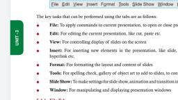
Chapter, , 3, , Word Processing, , Unit - 3, , 3.1, , Introduction, , A word processing software is required for the creation of documents that are text-based. It, has tools that allow the user to edit, format and print document. A word document may also, contain pictures and tables. It may be a report, letter, drawing, webpage etc., OpenOffice Writer is a popular open source software for word processing. It can be, downloaded from Internet and installed for free, on Linux-based machines as well as, Windows-based machines. In this chapter we discuss the usage of OpenOffice Writer, software in detail., , 3.2, , Start Openoffice Writer, , To start using the OpenOffice Writer software, any one of the following steps needs to be, performed<Start> <Programs> <OpenOffice>, , u, , If the OpenOffice icon (Figure 3.1) is on the desktop, double click the icon shown in, Figure 3.1., , u, , Figure 3.1: OpenOffice icon, , 46
Page 59 :
3.3, , Openoffice Screen and its Components, , The main screen of OpenOffice Writer is shown in Figure 3.2. It consists of different, components like Tabs, Ruler bar, Status bar, Scroll bar and Work Area. The Writer layout, and its general features are described as follows:, , Unit - 3, , Figure 3.2: OpenOffice Writer Screen, u, , u, , u, , u, , u, , Tabs: (File, Edit, View, Insert, etc.) contain drop down menu which have commands, provided by the tab., Ruler Bar: There are two rulers – Horizontal and Vertical. The Ruler Bar allows us, to adjust the indentation and margins., Status Bar: It displays information about the current open document. It displays the, current page number, total pages in the document, zoom slider etc., Scroll Bar: There are two scroll bars – horizontal and vertical. They help to scroll the, content or the body of document., Work area: It is the working area where the text of the document is typed., Hide Status Bar - <View><Unselect Status Bar>, , IT Tools Level - 3, , 47
Page 60 :
3.4, , Writer Tabs, , The OpenOffice Writer has the following tabs: File, Edit, View, Insert, Format, Tools,, Modify and Window. There is also a help tab. On clicking any of the tabs, a drop down, menu appears which has several commands and options. Select the command that you want, to execute., , Unit - 3, , The key tasks that can be performed using the tabs are as followsu, , File: To apply commands to current document, to open or close document, , u, , Edit: For editing the current document, for example, cut, paste, , u, , View: For controlling display of document on the screen, Insert: For inserting new elements in document, like, comments, special characters,, graphics, and objects, , u, , Format: For formatting the layout and content of document, , u, , Tools: For spelling check, gallery of object art to add to document, to configure, menus, , u, , u, , Table: To insert, edit, delete a table in a text document, , u, , Windows: For manipulating and displaying document windows, , 3.4.1 File Tab, The OpenOffice Writer is used to create a text document. The document is stored as a file, in the computer with the extension .odt. For example, a document stored as a file Anita.odt., The File tab consists of commands required to perform operations on a file (document). It, contains several commands as shown in Figure 3.3 (a). The commands which are required, to be known at this stage are described in the figure. The commonly used commands allow, the user to – create, save, print, open and close a text document. We use the words file and, document interchangeably., , 48
Page 61 :
Unit - 3, , Figure 3.3(a): File tab, , Figure 3.3(b): The New Option, , IT Tools Level - 3, , 49
Page 62 :
Some operations performed using the commands of the File tab are described as follows Using New: When you click <File><New>, a drop down menu appears Figure 3.3, (b). To create a document, select <Text Document>., , u, , Using Save As: This is used when you want to, , u, , (1) Save a file for the first time, or, (2) Save an already saved file with a different name., , Unit - 3, , When you click <File Tab> <Save As>, a Save As dialog box appears Figure 3.4. You can –, r, , Select folder (directory) where the file is to be saved,, , r, , Type the File name for the document,, , r, , Select “save as type” of document (.odt etc.), , r, , Click “Save: button to save the file., , Figure 3.4: SaveAs option, , To preview your document before printing: <File><Page Preview>. You can see, how the printed page will look like after printing. You can see multiple pages, full, , u, , 50
Page 63 :
pages (use magnifying glass to zoom in and out). Click <Close Preview> to go back, to the document., u, u, , To Make Printer Setting: <File Printer Setting>. Make settings for the printer., To Print:<File><Print>: Print the document to the connected printer. You can select the size of, the paper, print multiple pages on a single sheet etc., , 3.4.2 Edit Tab, The Edit tab consists of commands required to perform editing on the current document. It, contains several commands as shown in Figure 3.5. The commands which are required to, be known at this stage are described in the figure. The commonly used commands allow the, user to – cut, copy, paste, find & replace, undo and redo changes in the current document., , Unit - 3, , Figure 3.5: The Edit Tab, , IT Tools Level - 3, , 51
Page 64 :
Some operations performed using the commands of the Edit tab are described as follows:, Move Text: Remove the text to be moved by selecting the text and then applying, <File><Edit><Cut>. Then take the cursor to the place in document where you, want to move the text. Then do <File><Edit><Paste>., , u, , Copy Text: Select the text to be copied and then apply <File><Edit><Copy>. Then, take the cursor to the place in document where you want the copied text. Then do, <File><Edit><Paste>., , u, , Find and Replace: This is used to find words and then replace it with the new one, (Figure 3.6). This option is useful to find word at multiple places in the document and, replace all of them with the new one., , Unit - 3, , u, , Figure 3.6: Find and Replace dialog box, , 3.4.3 View Tab, The View tab consists of commands required for viewing the current document on the, screen. It contains several commands as shown in Figure 3.7. The commands which are, required to be known at this stage are described in the figure. The commonly used commands, allow the user to view status bar, ruler, sidebar etc., , 52
Page 65 :
Unit - 3, , Figure 3.7: View Tab, , Figure 3.8: View Toolbar Options, , IT Tools Level - 3, , 53
Page 66 :
Some operations performed using the commands of the Edit tab are described as follows u, , Toolbars: Select <View><Toolbars>. A drop down menu appears, as shown in, Figure 3.8. Select the toolbars that you want to be displayed on the screen. A displayed, toolbar shows the icons for the commands, as shown in Figure 3.8. Generally, Standard, and Formatting options of toolbars are always selected., , Figure 3.8: Toolbar on screen, , Unit - 3, , 3.4.4 Insert Tab, The Insert tab consist of commands required for inserting different elements in a document., It contains several commands as shown in Figure 3.9. The commands which are required to, be known at this stage are described in the figure. The commonly used commands allow the, user to insert page number, date, header, footer, tables, hyperlinks etc. in the current document., , Figure 3.9: Insert Tab, , 54
Page 67 :
When using an Insert tab to insert an element, the insertion of element in the document, happens at the location where the cursor is present on the screen. So you must place the, cursor at the right location on the screen before inserting the element. Also, when using, insert, a dialog box may open for further settings and selection. Please choose the options, in the dialog box and proceed further. The dialog box are self-explanatory. Some operations, performed using the commands of the Insert tab are described as follows u, , u, , u, , u, , u, , u, , Insert Footer: <Insert> <Footer> <Default>: A Footer box opens in the lower part, of the document. Enter the content you want to write in the header., Insert Fields: <Insert> <Fields>: A pop-up menu appears (Figure 3.10). Select the, element to be inserted. The selected element will insert at the location of the cursor., If you want to insert the field in the header or footer, then first select header/footer., Place the cursor in the correct position and then insert page number, time, date,, author name, etc., Insert Hyperlink: <Insert> <Hyperlink>: A dialog box opens. On the left side of, the dialog box, select where you want to link – a webpage, document, mail or to a, new document. Then fill the details path, Form (text, button), etc. The Text is the, name that appears in your document as hyperlink. Figure 3.11 shows an example., Insert Table of Content: <Insert> <Indexes & Tables> <Indexes & Tables>: A, dialog box appears. In Type, select Table of Content. Click OK. A table of content, will be inserted in your document., Insert Table: <Insert> <Table>: A dialog box appears. Enter the table name, number, of rows and columns. Click OK. A table is inserted in the document. A table toolbar, appears which allows you to format the table., Insert Formula: <Insert> <Object> <Formula>: A pop up menu of elements, appears (Figure 1.12a). Select the element and write the formula. Figure 1.12b shows, an example., , IT Tools Level - 3, , 55, , Unit - 3, , u, , Insert Header: <Insert> <Header> <Default> : A Header box opens in the upper, part of the document. Enter the content you want to write in the header.
Page 68 :
Unit - 3, , Figure 3.10: Insert Fields Option, , Figure 3.11: Example of Insert Hyperlink, , 56
Page 69 :
Figure 3.12: Insert Formula (a) Formula menu (b) An example, , 3.4.5 Format Tab, , Figure 3.13: Format Tab, , IT Tools Level - 3, , 57, , Unit - 3, , The Format tab consist of commands required for formatting the document. It contains, several commands as shown in Figure 3.13. The commands which are required to be known, at this stage are described in the figure. The commonly used commands allow the user to, format a page, paragraph, insert bullets, styles, formatting, etc. in the current document.
Page 70 :
When using the Format tab, the formatting happens on the text that has been selected. So, you must select the text on which the formatting has to be applied and then use the relevant, command from the Format tab. Some operations performed using commands of the Format, tab are described as follows:, u, , u, , Unit - 3, , u, , u, , u, , u, , u, , Format Character: <Format> <Character>: A dialog box opens (Figure 3.14). Select, the font type, typeface, and size. Select font effects, background etc. The changes happen, to the text selected., Format Paragraph: <Format> <Paragraph>: A dialog box opens (Figure 3.15). You, can change the indentation and spacing, borders, alignment, etc., Format Bullets and Numbering: <Format> <Bullets and Numbering>: A dialog box, opens (Figure 3.16). You can select from bullets of different kinds or numbering. In the, document the bullets are inserted at the location at which the cursor is present., Format Page: <Format> <Page>: A dialog box opens (Figure 3.17). This allows to, format the whole page – borders, color, alignment, number of columns etc., To Change case of Text: <Format> <Change Case>: A dialog box opens, (Figure 3.18a)., To Change Number of Columns: <Format> <Columns>: A dialog box opens. You can, select 2-column page, three column page etc., To Change Alignment of Text: <Format> <Alignment>: A dialog box opens (Figure, 3.18b). Select from left, right, centered, and justified., , Figure 3.14: Format Character, , 58
Page 71 :
Unit - 3, , Figure 3.15: Format Paragraph, , Figure 3.16: Format Bullets and Numbering, , IT Tools Level - 3, , 59
Page 72 :
Unit - 3, , Figure 3.17: Format Page, , Figure 3.18: Format (a) Change Case (b) Alignment, , 3.4.6 Table Tab, The Table tab consists of commands that operate on a table. It contains several commands, as shown in Figure 3.19. The commands which are required to be known at this stage are, described in the figure. The commonly used commands allow the user to insert a table, insert, or delete rows, or columns in a table, etc. in the current document., , 60
Page 73 :
Unit - 3, , Figure 3.19: Table Tab, , Figure 3.20: Table Toolbar, , When using the Table tab, a new table is inserted at the location of the cursor on the screen., For merge or split, select the cells on which the operation has to be applied. When a table is, inserted, a table toolbar appears for the formatting of the table (Figure 3.20). Some operations, performed using the commands of the Table tab are described as follows u, , Convert Table to Text or Text to Table: <Table> <Convert>: A pop up menu, appears. If text is to be converted to table, the Text to Table option appears, Select it, , IT Tools Level - 3, , 61
Page 74 :
to convert text to table. If a table is already present, then Table to Text option appears., Select it to convert table to text., 3.4.7 Tools Tab, , Unit - 3, , The Tools tab consists of commands that can be used on the document for better results. It, contains several commands as shown in Figure 3.21. The commands which are required to, be known at this stage are described in the figure. The commonly used commands allow the, user to check spelling and grammar of the content in the document, and count the number, of words and characters in the document., , Figure 3.21: Tools Tab, , Some operations performed using the commands of the Tools tab are described as follows Check Spellings and Grammar: <Tools> <Spelling and Grammar>: The grammar, and spelling of the document is checked. A window as shown in Figure 3.22 appears, if there are no grammatical and spelling errors in the document. If errors are there,, , u, , 62
Page 75 :
then the errors are displayed with suggestions of correcting it. The user can decide to, accept the suggestion or ignore it., u, , Find Number of Words: <Tools> <Word Count>: If the text is already selected,, then word count displays the number of words and characters in the selected text., Otherwise the word count displays the number of words and character in the whole, document (Figure 3.23)., , Unit - 3, , Figure 3.22: Tools Spelling and Grammar, , Figure 3.23: Tools Word Count, , IT Tools Level - 3, , 63
Page 76 :
3.4.8 Window Tab, The Window tab consists of commands that work on a window, as shown in Figure 3.24., The commands in this tab allow the user to open a new window or close an existing window., Also, the name of all currently open windows is also displayed., , Figure 3.24: Window Tab, , Unit - 3, , 3.4.9 Help Tab, The Help tab consists of commands that provide help to the user of the OpenOffice Writer, software. On clicking on the help tab, a screen as shown in Figure 3.25 appears. You can, browse the Help for the command you want., , Figure 3.25: Help Tab, , Points to Remember, u A, , word processing software has tools that allow creation of text-based documents., , u OpenOffice, , Writer is an open source software for word processing., , u OpenOffice, , Writer consists of different components like tabs, ruler bar, status bar,, scrollbar and work area., File, Edit, View, Insert, Format, Tools, Modify and Window are the tabs in OpenOffice, Writer., , u, , File tab consists of commands like, create, save, print, open and close., , u, , u Save, , As option is used to save a file for the first time, or save an already saved file with, a different name., , 64
Page 77 :
u Edit, , tab consists of commands for editing a document, like, cut, copy, paste, find &, replace, undo and redo changes., , u, , Move Text moves the text from the current location to the target location., , u Copy, u, , Text copies the text from the current location to the target location., , View tab consists of commands like, view status bar, ruler, sidebar, that help during, viewing a document on the screen., , u Insert, , tab allows insertion of page number, date, header, footer, tables, hyperlinks in, a document., , u, , Format tab consist of commands to format a page, paragraph, insert bullets, styles,, formatting in a document., tab commands operate on a table - insert table, insert/delete rows/columns in, a table, in a document., , u Tools, , tab consists of commands to check spelling and grammar of content in the, document and count words/characters., , u, , Window tab allow the user to open a new window or close an existing window., , u The, , user can use Help tab to understand the working of any command of the, OpenOffice Writer., , Exercises, 1., , What is the need of a word processing software?, , 2., , What is the task of a word processing software?, , 3. Name an open source word processing software., 4. List the steps to start an OpenOffice Writer., 5. List the components of the main screen of OpenOffice Writer., 6. Define the following:, a. Tabs, b. Ruler Bar, c. Status Bar, , IT Tools Level - 3, , 65, , Unit - 3, , u Table
Page 78 :
d. Scroll Bar, e., , Work Area, , 7. List the tabs in the OpenOffice Writer. What are the key tasks performed by the tabs., 8., , What is the extension of the file created in OpenOffice Writer?, , 9., , What is the purpose of the following tabs?, a., , File, , b. Edit, c., , View, , d. Insert, Unit - 3, , e., , Format, , f. Table, g. Tools, 10., , What is the difference between Save command and Save As command?, , 11., , What is the difference between Move text and Copy text?, , 12. How is Find and Replace option useful., 13. List the steps for inserting a hyperlink to a web page in a document., 14., , What is the difference between toggle case and sentence case when using change, case?, , 15. Name the tabs in which the following commnds are present:, a. Header, b., , Find&Replace, , c. Status Bar, d. Ruler, e. Hyperlink, f., , Formula, , g., , Paragraph, , h. Alignment, i., , 66, , Word and Count
Page 79 :
16. Use OpenOffice Writer to create the following documents:, a. A Birthday invitation card., b. A farewell invitation card., c. A one page article that lists the steps that you take to clean the environment, (use bullets). Format the page. Insert header and footer in the document., d., , Write the quadratic equation using formula symbols., , e. A grocery bill using tables. Then convert this table to text., f. A 2-page 2-column article having pictures and text. Create a hyperlink to a, web page. Also state the number paragrahs, lines, words and characters in the, document. Perform spell check on the document., g., , 67, , Unit - 3, , IT Tools Level - 3, , Create a document with text and then use find and replace option to replace, a word in the document.
Page 80 :
Chapter, , 4, , Unit - 3, , 4.1, , Spreadsheet, (OpenOffice Calc), , Introduction, , A spreadsheet stores data in the form of a table comprising of rows and columns. It is used, to store, arrange, and sort data, and perform calculations on numeric data. It is similar to the, ruled paper accounting worksheets traditionally used for bookkeeping. The computerized, version of a worksheet is called a Spreadsheet application that lets you quickly perform, calculations on numerical data, represent data with charts, analyze, and print. Spreadsheets, are used in various fields such as banking, finance, accounting, and education. Following are, some of the popular uses of spreadsheets:, 1., , Managing financial data such as bank account information, budgets, transactions,, billing, and receipts., , 2. Handling inventory, reviews, employee information, surveys, etc., using data entry, forms., 3. Tracking student performance by calculating grades and other relevant information, such as attendance, highest score, and lowest score., 4. Creating lists of items which may not be numeric such as student list, grocery list., 5., , Managing company information such as profit and sales by creating graphs from the, data., , There are various spreadsheet applications available that can be used to create and, manipulate a spreadsheet. The most commonly used are – Microsoft Office Excel, Apache, OpenOffice Calc, LibreOffice Calc, Google Sheets etc. Microsoft Excel is a proprietary, software from Microsoft for Windows. Both OpenOffice and Libre Calc are free and opensource alternatives to Excel. Google sheets is a web-based spreadsheet application which, allows you to store and edit the spreadsheets online and access them from any computer. In, this chapter we’ll study spreadsheets using Apache OpenOffice Calc. Figure 4.1 shows how, an OpenOffice Calc spreadsheet looks like., , 68
Page 81 :
Figure 4.1: OpenOffice Calc Spreadsheet, , 4.2, , Installing Calc, , 1. Open the URL: https://www.openoffice.org/download/index.html., 2. Select the operating system and language., 3. Click on – Download full Installation, 4. Installing OpenOffice on Windows, a. Double click on the downloaded exe file and then click Next on the following, screen:, , IT Tools Level - 3, , 69, , Unit - 3, , Calc is offered free of charge and can be downloded from HYPERLINK ‘http://www., openoffice.org’ www.openoffice.org calc is the spreadsheet component of Apache OpenOffice, an open source office software suite. We will install the complete Apache OpenOffice which, include calc
Page 82 :
Unit - 3, , b. Click on Unpack, , c. After unpacking, click on Next, , 70
Page 83 :
d. Enter User information and then click on Next, , Unit - 3, , e. Choose the setup type and then click on Next. It is recommended that the, beginners should choose typical., , IT Tools Level - 3, , 71
Page 84 :
Unit - 3, , f. Click on Install, , g. After installation, click on Finish, , 72
Page 85 :
h. Run OpenOffice to check if it has been installed successfully., i. Click on the Spreadsheet to open OpenOffice Calc., , Unit - 3, , 4.3, , Main Features of OpenOffice Calc, , Calc offers the several features. In this section, we shall describe several features. If you do, not understand everything, do not worry about it. Things will become clear as we move on., 4.3.1 Starting Calc, To start OpenOffice Calc, there are various ways in which you can start it:, u As, u If, , a Windows application, you can click Start -> Programs ->OpenOffice, , the OpenOffice icon as shownin Figure 4.2 is on the desktop, double click the icon., , Figure 4.2: OpenOffice Icon, , IT Tools Level - 3, , 73
Page 86 :
Calc’s default file format is the Open Document Format (ODF), an ISO/IEC standard,, which originated with OpenOffice.org., 4.3.2 Calc Main Window, , Unit - 3, , Before using Calc to create spreadsheets, let us study the various menus and toolbars, available in the main window of Calc as shown in Figure 4.3., , Figure 4.3: Main Window of Calc, , Title Bar: The title bar at the top displays the information about the spreadsheet such, as name of the current spreadsheet (ExampleSheet), extension of the spreadsheet, (.ods), and name of the software (OpenOffice Calc). If the spreadsheet is new then, its name is Untitled N where N is a number. The ellipsis (three dots ...) in front of an, option implies that a dialog box will open when this option is selected. For example,, on selecting the Open option, a dialog box will appear which is meant for the user to, enter the location of the file to be opened., , u, , Menu Bar: Just below the title bar is the menu bar. It contains various menu options., On selecting a menu option, a submenu appears which contains other options related, to the main menu option. The menu options and few of their submenu options are, discussed below:, , u, , 74
Page 87 :
, , , , , , File: It contains commands to create a new file (New), open an existing file, (Open), save a file (Save , Save As), print a file (Print), preview a page (Preview, Page), close a file (Close), exit the software (Exit) etc., Edit: It contains commands to edit a file such as Cut, Copy, Paste, Paste, Special, Select All, Find & Replace, Delete Contents, Delete Cells, Headers &, Footers., View: It contains commands to modify the view of the Calc such as Toolbars,, Full Screen, Zoom. A small in front of the Toolbars options means on selecting, it, another submenu appears as shown in Figure 4.4 which shows the list of all, the toolbars which can be selected or deselected based on the user’s choice of, toolbars to be displayed on the Calc main window., , Unit - 3, , Figure 4.4: Toolbars Options, , , , , , , , , , IT Tools Level - 3, , Insert: It contains commands for inserting Cells, Rows, Columns, Sheet,, Sheet From File, Function, Function List, Picture, Chart etc., Format: It contains commands to alter the layout of the spreadsheet such as, formatting Cells, altering Rows, Columns, Sheet., Tools: It contains options to o spellcheck (Spelling), insert macros (Macros), etc., Data: It contains commands to manipulate data such as Sort, Filter, Validity., Window: It contains commands to modify the window such as New Window,, Close Window., , 75
Page 88 :
, , Standard Bar: It lies below the Menu bar. It contains icons which perform similar, operations as contained in the Menu bar options such as New, Open, Save, Print,, Page Preview, Cut, Copy, Paste, Sort, Chart, Find & Replace, Spelling., , u, , Find Bar: It contains a text box which can be used to enter text which is meant to, be searched in the spreadsheet. It highlights the cell which contains the text to be, searched. Multiple search results can be traversed by clicking on the up and down, arrows or by pressing the Enter key on the keyboard., , u, , Unit - 3, , Help: It contains the options getting help related to OpenOffice Calc such as, OpenOffice Help, What’s This?, Check for Updates etc. Placing the mouse, pointer on any of the icons on the Calc window displays a small box which, is called a tooltip which gives a brief explanation of the icon’s function. For, a more detailed explanation of any icon or function, select Help > What’s, This? and hover the mouse pointer over the icon or function. To turn this, feature off again, click once or press the Esc key twice., , Formatting Bar: In the Formatting toolbar, the leftmost icon is for the Style &, Formatting and the following two boxes are the Font Name and Font Size lists. They, show the current settings for the selected cell or area. Click the down-arrow to the, right of each box to open the list., , u, , , , , , , , , , , , , 76, , Following the boxes, we have the three icons for changing the appearance of, the text such as making the text bold ( ), italics ( ), and underlining ( )., Next we have the icons which are used to align the text within a cell as left (, ), center ( ), right ( ), or justify ( )., Merge cells icon ( ) is used to merge multiple cells and form a single cell. It, becomes active when multiple cells are selected., Format of numbers can be changed by using the Number format icons –, Currency ( ), Percent (, Decimal Place ( )., , ), Standard (, , Indentation of text can be increased (, the indent arrows., , ), Add Decimal Place (, ) or decreased (, , ), Delete, , ) within a cell using
Page 89 :
, , , , , , u, , Borders of cells can be modified by using the border styles available by clicking, on the drop-down of the Border icon (, )., Background Color of cells can be changed by clicking the Background Color, icon (, ). Click on the drop-down for more options of colors., Text color can also be changed by clicking the Font Color icon (, on the drop-down for more options of colors., , ). Click, , Formula Bar: On the left side of the Formula bar is the Name box which contains a, letter and name combination such as C4, whenever you select a cell on the spreadsheet., This combination is called as a cell reference. The cell reference is the address of a, cell. The letter is meant for the column and the number for the row., , The contents of the current cell (data, formula, or function) are displayed in the Input, line, which is the remainder of the Formula Bar. You can either edit the cell contents, of the current cell here, or you can do that in the current cell. To edit inside the Input, line area, click in the area, then type your changes. To edit within the current cell, just, double-click the cell., u, , Sheet Tabs: A single spreadsheet Calc file can contain multiple sheets. You can, traverse individual sheets by using the Sheet tabs. The current active sheet has a, white tab. Clicking on another sheet tab displays that sheet, and its tab turns white., Right click on the Sheet tabs will display various options such as inserting, deleting,, renaming, moving sheets, as shown in Figure 4.5., , IT Tools Level - 3, , 77, , Unit - 3, , To the right of the Name box, one can see the Function Wizard ( ), Sum ( ),, Function ( ) icons. Function Wizard opens a dialog box from which you can search, through a list of available functions. Sum icon inserts a formula into the current cell, that totals the numbers in the cells above the current cell. If there are no numbers above, the current cell, then the cells to the left are placed in the Sum formula. Function icon, inserts an equals (=) sign into the selected cell and the Input line, thereby enabling the, cell to accept a formula. When new data is entered into a cell, the Sum and Function, icons change to Cancel ( ) and Accept ( ) icons.
Page 90 :
Unit - 3, , Figure 4.5: Menu displayed when you right-click any Sheet tab, , Status Bar: Status bar at the bottom provides information about the spreadsheet and, convenient ways to quickly change some of its features. Sheet Sequence number shows, the number of the current sheet / total number of sheets in the spreadsheet as shown in, Figure 4.6., , u, , Selected cell (or cells) information is also displayed on the Status bar. When a group, of cells is selected, the sum of the contents is displayed by default. You can right-click, on this field and select other functions, such as the average value, maximum value,, minimum value, or count (number of items selected) as shown in Figure 4.6., , Figure 4.6: Displaying Information of Selected Cells in Status Bar, , 78
Page 91 :
When the cursor is on an object such as a picture or chart, the information displayed, includes the size of the object and its location as shown in Figure 4.7. To change the view, magnification, drag the Zoom slider (bottom left corner) or click on the + and – signs., , Unit - 3, , Figure 4.7: Information of Chart Displayed in the Status Bar, Zoom Slider, u, , u, , u, , u, , Sidebar: Located on the right side of the edit views of Calc, sidebar contains, frequently used tools grouped in decks such as Properties, Styles and Formatting,, Gallery, Navigator. Clicking on any of the vertical tabs opens the deck for that tab., Active Cell: When you select a cell, you will notice a heavy black border around the, selected cell as shown in Figure 4.3. The heavy black border indicates that selected, cell is the active cell., Row Headers: Row headers are in the form of numbers -1,2,3.... which are present, at the left of each row., Column Headers: Column headers are in the form of alphabets – A,B,C,...shown at, the top of each column., , IT Tools Level - 3, , 79
Page 92 :
4.3.3 Working with Spreadsheets, A Spreadsheet consists of a number of individual sheets, each containing cells arranged in, rows and columns. A particular cell is identified by its column letter and row number. These, cells hold the individual elements—text, numbers, formulas, and so on—that make up the, data to display and manipulate. Each spreadsheet can have many sheets and each sheet can, have many individual cells., Create a New Blank Worksheet : There are many ways to create a new blank, worksheet as discussed below:, , u, , On the menu bar, click File-> New->Spreadsheet as shown in Figure 4.8., , Unit - 3, , , , Figure 4.8: Creating New Blank Spreadsheet Using File Menu, , , 80, , On the Standard bar, click on drop-down of the New icon (, as shown in Figure 4.9., , ) -> Spreadsheet
Page 93 :
Figure 4.9: Creating New Blank Spreadsheet Using Standard Bar, , u, , On the keyboard type – Ctrl + N. The keyboard shortcuts are also displayed, next to the menu options as shown in Figure 4.8 and Figure 4.9., , Open an existing Spreadsheet :, , , On the menu bar, click File->Open as shown in Figure 4.8 and then a dialog, box opens up which is used to locate the spreadsheet to be opened as shown, in Figure 4.10., , Figure 4.10: Open Dialog Box, , IT Tools Level - 3, , 81, , Unit - 3, ,
Page 94 :
, , On the Standard bar, click on the Open icon (, ). Click on the drop-down, to open a list of recently opened OpenOffice files., , Navigating within Spreadsheets: There are many ways to navigate within a, spreadsheet from cell to cell and sheet to sheet., , u, , Accessing a particular cell – Place the mouse pointer over the cell and click to, access that cell. Another way is to type the cell reference or address in the Name, box in the Formula bar and press Enter. For example, if you want to access, cell D5, then type D5 in the Name box and press Enter. You can see cell D5 is, highlighted as shown in Figure 4.11., , Unit - 3, , , , Figure 4.11: Accessing a Cell using Name Box, , You can also use the Calc Navigator ( ) on the Standard bar or Press F5 which, opens the following Navigator dialog box in which you can enter the row number and, column letter which you want to access., , 82
Page 95 :
, , , , Cell to Cell Navigation: You can use the Mouse and various keys on the, keyboard such as Tab, Enter keys, and Arrow keys to navigate from one cell, to another., Sheet to Sheet Navigation: Using sheet tabs at the bottom of the spreadsheet,, you can navigate between sheets. If you have a number of sheets, then some of, the sheet tabs may be hidden behind the horizontal scroll bar at the bottom of the, screen. If this is the case, then the four buttons at the left of the sheet tabs as shown in, Figure 4.13 can move the tabs into view., , Figure 4.13: Sheet Navigation, u, , Saving Worksheet:, , , On the menu bar, click File->Save as shown in Figure 4.8., , , , On the Standard bar, click on Save icon (, , IT Tools Level - 3, , )., , 83, , Unit - 3, , Figure 4.12: Calc Navigator
Page 96 :
Unit - 3, , While saving a new spreadsheet for the first time, a dialog box will open to enter a name and, select the location for saving the spreadsheet. For example, in Figure 4.14 a spreadsheet file, is saved on the Desktop with the name ExampleSheet and type .odf., , Figure 4.14: Saving a Spreadsheet, u, , Closing Worksheet:, , , On the menu bar, click File->Close (Figure 4.8). A dialog box opens up if the, spreadsheet has not been saved as shown in Figure 4.15. The dialog box gives, options to the user to Save the file, Discard the changes or Cancel the close, operation., , Figure 4.15: Save Dialog Box on Closing a File, , , You can also directly close the OpenOffice Calc main window., , 4.3.4 Working with Data:, Data – There are various types of data that can be entered in a cell:, , u, , 84
Page 97 :
, , , , , , u, , Labels – These are alphabetic or alphanumeric entries without numeric value., They can be a combination of letters, numbers, space, special characters etc., Labels are left justified by default., Numbers or Values – These are numeric data which may be integers or can, contain decimals or fractions. Values are right-justified by default., Formulas – Used to perform calculations such as addition, subtraction,, multiplication, division, average. Formulas must begin with an = sign., , Entering Data: Data can be entered in an active cell. Following are the steps to enter, data in say cell A1 (Figure 4.16):, i) Click on the A1 cell which is at the top left of the spreadsheet. The heavy, black border around the A1 cell indicates that it is the active cell., , iii) On pressing Enter the cell below becomes the next active cell. Now the active, cell is now A2., Figure 4.16: Entering Data in Cell A1, u, , Moving Data within a Spreadsheet: For moving data from one cell to another we, have the cut-copy-paste functions. There are various ways to use these functions as, described below:, , , Using the Edit Menu: The Cut, Copy, and Paste functions are available in the, Edit menu. Following example illustrates the steps to do cut/copy-paste using, Edit Menu:, i) Select the cell whose contents you want to cut or copy (say cell D5)., ii) Go to the Edit menu on the menu bar and click on Cut/Copy., iii) Select the cell where you want to paste the contents of cell D5 (say cell, F5)., iv) Go to the Edit menu and click on Paste. If you have selected Cut option, then the contents of D5 will be removed from D5 and pasted in F5., But if you have selected the Copy option, then the contents of cell D5, will remain in intact and the same will be copied in F5., , , , IT Tools Level - 3, , Using the Standard bar: The icons are Cut ( ), Copy ( ), and Paste (, )., Following example illustrates the steps to do cut/copy-paste using Standard, bar:, , 85, , Unit - 3, , ii) Start typing some text or numbers say “Room 1” and press Enter.
Page 98 :
i) Select the cell whose contents you want to cut or copy (say cell D5)., ii) Click on the Cut / Copy icon in the Standard bar., iii) Select the cell where you want to paste the contents of cell D5 (say cell, F5)., iv) Click on the Paste icon in the Standard bar., , , By Right -Click: Following example illustrates the steps to do cut/copy-paste, by right clicking on the cell:, , Unit - 3, , i) Right-Click on the cell whose contents you want to cut or copy (say, cell D5). The following menu is displayed:, , Figure 4.17: Right-Click Menu, , ii) Select the option Cut/Copy., iii) Right-Click on the cell where you want to paste the contents of cell D5, (say cell F5)., iv) Select the Paste option., , 86
Page 99 :
, , Using AutoFill: This feature in Calc is used to automatically generate data, based on a defined series. A very common example is to enter numbers in the, serial number (S.No) column of a table. This is a very frequently used column, which usually contains consecutive numbers. Instead of manually typing the, serial numbers (say 1 to 100), you can use the AutoFill command in Calc. The, procedure to generate the series of numbers from 1 to 5 is as follows (Figure, 4.18):, i) Click on the first cell of the serial number column and type 1., ii) Now drag the fill handle in the bottom right corner of the cell (a solid white, + sign) across the cells that you want to fill (in the given example till 5), and release the mouse button. The cells will be filled with ascending, numbers 2, 3, 4, 5., , Unit - 3, , Figure 4.18: Using AutoFill, , Try doing the same exercise with “Monday” typed a cell and you’ll observe, that the subsequent cells will be filled with the days – Tuesday, Wednesday,…., etc., The AutoFill command also recognizes customized sort lists that are defined, under menu Tools -> Options -> OpenOffice Calc -> Sort Lists. You can also, define your own sort list., In case you want to enter the same value, say, 1 in 10 consecutive cells simply, press the Ctrl key while dragging the fill handle., Suppose you want to enter even numbers in a column. For example entering, 2, 4, 6, 8….20. Then follow the procedure:, i) Type the first two values (2 and 4) in the first two cells., ii) Then select both the cells and drag the fill handle of the cell containing, value 4. You will observe that now the values filled by Calc will be 6,, 8, 10…20., , IT Tools Level - 3, , 87
Page 100 :
Thus if you want to generate your own series, then you have to specify two, values so that Calc can determine how to generate the subsequent values., 4.3.5 Formatting Data, , Unit - 3, , Formatting a document means adding elements of style and presentation to documents, to improve the readability and make them more attractive. To enhance the appearance of, spreadsheets various formatting options are available in the Formatting Bar and Format, Menu such as alignment, font, size, and style. Various formats for numbers are also available, such as percentage and decimals. Following are the various formatting options available on, the Formatting Bar as shown in Figure 4.19., , Figure 4.19: Formatting Bar, , Numbers as Text: Calc evaluates each cell and determines whether the entry is a, Value or Label. Cells containing a combination of values and text is automatically, treated as a label such as code of a product - COMP123. Such entries cannot be used, for calculations. However there might be a requirement that a cell containing numbers, be treated like a label. For example telephone numbers, aadhar card number, ZIP, codes etc. should be treated as labels and not values. Whenever such a requirement, arises, prefix each such entry with a single quotation mark (‘). The quotation mark, will be invisible and the numbers in the cell will be treated as labels., , u, , Font: Font refers to the design for a set of characters. It is the combination of typeface, and other qualities, such as size, pitch, and spacing. The font can be changed from the, Formatting bar., , u, , 88
Page 101 :
Let us discuss various Font changing options on the Formatting bar:, , , Font Name: Various font types are there in Calc such as Arial, Arimo, and, Century Schoolbook L. The font type can be selected from the Font Name, box in the Formatting bar as shown in Figure 4.19. Using the drop down, you, can select from the list of font types available in Calc. The appearance of the, font types listed in the drop down is how the text will look when a font type, setting is applied as shown in Figure 4.20., , Unit - 3, , Figure 4.20: Font Names, , , , , u, , Font Size: Click on the drop down arrow of the font size which is next to the, Font Name box and then select the size you want to use., Font Style: You can also make the text bold, italics or underlined by clicking, on the, , or, icons available on the formatting bar respectively., , Horizontal Alignment: Alignment of data in cell with respect to the border of the, cells can be done by using the Alignment options:, , , , , , IT Tools Level - 3, , Left Align, , : The left edge of the text is along the left cell border., , Center Align, : Both the left and right edges are equally distant from the, left and right cell borders respectively., Right Align, , : The right edge of the text is along the right cell border., , 89
Page 102 :
, , Justify, , : Aligns the text to the left and the right cell borders., , Changing Color : You can easily change the color of the background of the cells as, well as the text color as shown in Figure 4.21. On the left the background color is, changed and on the right the text color is changed., , u, , Figure 4.21: Background and Text Color Change, , Steps to change the background color of cells:, Unit - 3, , i) Select the cells., ii) Click on the Background color icon, , ., , iii) Select the color from the palette as shown in Figure 4.22., , Figure 4.22: Background Color Palette, , Steps to change the text or font color:, i) Select the text or you can select the complete cells., , 90
Page 103 :
ii) Click on the Text color icon, , ., , iii) Select the color from the palette as shown in Figure 4.23., , Unit - 3, , Figure 4.23: Font Color Palette, u, , Gridlines and Borders : The gray gridlines (vertical and horizontal lines) that you can, see in a Calc spreadsheet help you while you’re working in a spreadsheet. Gridlines, appear automatically showing you how the data is organized into rows and columns., Borders are different from gridlines because they help you highlight important, information for people to see as shown in Figure 4.24., , Figure 4.24: Gridlines and Borders, , IT Tools Level - 3, , 91
Page 104 :
Unit - 3, , Borders need to be added if you want to highlight certain cells. One more difference, is that gridlines aren’t automatically printed, while borders are. Thus, to draw borders, around a cell or multiple cells, you can use the Border icon on the Formatting bar, . A drop down (Figure 4.25) in the same icon provides various options to draw, the left or right or top or bottom border, all borders, outer border etc. In order to, create borders, select the cells around which you want borders and then click on the, required border option., , Figure 4.25: Borders, , Flow of Text: In order to control the flow of text within cells, Calc provides various, ways:, , u, , 1), , Merging / Splitting Cells: In order to merge cells, select the cells and click on, the Merge Cells, icon in the Standard Bar. To split the merged cells, select, the cell and click on the Merge Cells icon., , 2), , Wrap Text: It means to break the text into multiple lines i.e., adjusting the, row height to fit the text within the cell but keeping the column width of the, cell same. Steps to wrap text:, i) Right-click on the cell., ii) Select the option – Format Cells., iii) A dialog box opens up. Open the Alignment Tab and check the option, – Wrap text automatically as shown in Figure 4.26., , 92
Page 105 :
Unit - 3, , Figure 4.26: Wrap Text, , 3., , Shrink to Fit : This option shrinks the text to fit in the size of the existing cell., In this case neither the row height nor the column width is changed. The text, size is decreased according to the cell. Steps to shrink the text size to fit the cell:, i) Right-click on the cell., ii) Select the option – Format Cells., iii) A dialog box opens up. Open the Alignment Tab and check the option, – Shrink to fit cell size as shown in Figure 4.26., , Following example illustrates the difference between Wrap text and Shrink to fit. Given the, text “OpenOffice Calc” which cannot fit in a single cell as shown in Figure 4.27, we have, two options – either to wrap the text or to shrink it to fit the cell., , Figure 4.27: Difference between Wrap Text and Shrink to Fit, , IT Tools Level - 3, , 93
Page 106 :
Numeric Data Formatting, , u, , Unit - 3, , In Calc, there are many ways in which numerical data can be formatted i.e., changing, the appearance of numbers. Some of the number formats are available on the Standard, Toolbar (Currency , Percent , Standard , Add/Delete Decimal place, )., For more options, right-click on the cell and click on Format Cells to open a dialog, box as shown in Figure 4.28. Click on the Numbers tab and then you can select the, category of the format as per requirement., , Figure 4.28: Number Formatting Dialog Box, , Some of the commonly used number formats are discussed below:, 1., , 94, , Currency: In the currency format, you can prefix or suffix currency symbols, to the numeric data. The default currency is Rs. which is prefixed to the, number, commas are inserted at the thousand, million, billion positions, and, two decimal places are added to the number.
Page 107 :
2., , Percent: It displays the number as a percentage. Two decimal places are added, to the number and the percent symbol (%) is suffixed at the end., , 3., , Standard: It sets the number in the cell to the default format by removing any, other numeric formatting applied., , 4., , Decimals: Decimal places can be inserted or removed by using the Add, Decimal place or Delete Decimal place icon respectively., , Original, Number, , Currency, , Percent, , Add Decimal, Place, , Delete, Decimal Place, , 23456.78, , 23,456.78, , 2345678.00%, , 23456.78, , 23456.78, , Figure 4.29: Number Formats, , 5., , Date: By default the date format in Calc is dd/mm/yy. But in case you want, to change the format, you can find various date formats in the Format Cells, dialog box., , 4.3.6 Finding and Replacing Data, Data can be searched by using the Find toolbar. If you want to find and replace the data then, perform the following steps:, i) Click on the Edit menu and select the Find & Replace option., ii) A dialog box opens (Figure 4.30) in which you can type the text to be searched, in the “Search for” text box and the replaced text in the “Replace with” text, box. You can find or replace the results individually (Find or Replace) or all, of them at one go by clicking on the Find All or Replace All button., , IT Tools Level - 3, , 95, , Unit - 3, , If you want to remove fractional part of a cell or group of cells then you can, either use the Delete Decimal place icon on the Standard toolbar or another, option is to right-click on the cell (s) and then click on Format Cells to open, the dialog box. On the Number tab, you can see the Decimals spin box in the, Option section. You can increase or decrease the number of decimal places, by using the up and down arrows. Zeros can also be prefixed to the numbers, by setting the number of zeros to be prefixed in the Leading Zeros spin box., Figure 4.29 shows an example of how the number – 23456.78 changes when, different formatting options are applied on it.
Page 108 :
Unit - 3, , Figure 4.30: Find & Replace Dialog Box, , iii) The Match case check box when checked implies that the searching is, sensitive to the case of the text i.e., uppercase and lowercase letters are treated, differently. Otherwise uppercase and lowercase letters are treated as equal., iv) Entire cells check box when checked implies that Calc will search for the, whole words that are identical to the text to be searched and if the text to be, searched is part of some other text then it will not highlight that in its results., If this check box is not checked then the text to be searched is highlighted even, if it is part of cell contents., 4.3.7 Deleting, Delete Data: For removing data from a cell, click inside the cell (double-click) and, then press the Backspace key according to the text you want to delete. However if, you only select the cell (single-click) and then press the Backspace key then this will, result in the deletion of all the text within the cell, though the formatting of the cell, remains., , u, , Deleting Data and Formatting: Delete key (or Right-click the cell and select Delete, All option) can be used to remove data as well as the formatting from a cell. Selecting, the cell and pressing the Delete key opens a dialog box (Figure 4.31) which can be, , u, , 96
Page 109 :
used to delete different aspects of the cell. To delete everything in a cell (contents and, format), check Delete all., , Unit - 3, , Figure 4.31: Delete Contents Dialog Box, u, , Deleting Cell(s): Single or multiple cells can be deleted by selecting them and then, right-click and select the Delete option. On doing so, a dialog box (Figure 4.32) opens, which asks the user to shift cells up or left or delete an entire row or column after, deleting the cell(s)., , Figure 4.32: Delete Cells Dialog Box, , 4.3.8 Inserting/Deleting Rows and Columns, Sometimes when you have finished entering data in a spreadsheet you may need to add or, remove rows and columns. One way is to select the row or column by clicking on the row, header (number) on the left or column header (alphabet) on the top and then right-click. A, , IT Tools Level - 3, , 97
Page 110 :
Unit - 3, , menu appears (Figure 4.33) which can be used to insert and delete rows or columns and also, adjust the height or width of a row or column., , Figure 4.33: Row and Column Menus, , Insertion of row and columns can also be performed by using the Insert menu on the Menu, bar as shown in Figure 4.34., , Figure 4.34: Insert Menu, , 98
Page 111 :
4.3.9 Using Formulas and Functions, Formulas can be used for basic operations such as addition, subtraction, as well as more, complex calculations such as income tax calculations, averaging. The advantage of using, formulas is that even if the data is changed, Calc will automatically recalculate the answer, without the need to rewrite the formula again. Another advantage of using formulas is that, they can be easily copied to a number of cells., Let us study some examples of creating basic formulas in Calc., Example 1: Adding data in two numbers and storing the result in cell D6., Step 1: In cell D6, type the equal sign (=). This informs Calc that D6 will contain a, formula., , Step 3: Press Enter, Cell D6 will contain 9. You can see the formula (=4+5) in the Input line in the, formula toolbar as shown in Figure 4.35., , Figure 4.35: Example of Adding Two Numbers, , In the above example, we have used numbers for addition. What if we were supposed to add, the contents of cell D4 and D5 and then store the result in cell D6? This can be achieved, using cell reference or address of a cell., , IT Tools Level - 3, , 99, , Unit - 3, , Step 2: Now type 4+5
Page 112 :
In Calc, a cell reference identifies the location of a cell or group of cells in the worksheet. The, cell reference is also called address of a cell. Cell references are used in formulas, functions,, and other commands., , , Unit - 3, , , , , , Individual cell reference: Each cell is identified by its column letter and row, number in this order. For example, the cell reference of the topmost and, leftmost cell is A1 (Column=A, Row=1)., Range of cells – You can use cell referencing for a consecutive range of cells, also using a colon (:). For example, cell reference for the range of first five cells, in column D is D1:D5 (i.e., D1, D2, D3, D4, and D5). Cell reference for the, range of first five cells in row 5 is A5:E5 (i.e., A5, B5, C5, D5, and E5). Cell, reference for a group of four cells spanning first 2 columns and first 2 rows of, the spreadsheet is A1:B2 (i.e., A1, A2, B1, and B2)., When you wish to add a reference to a cell in some other cell then there are, two ways. First is to type the cell reference using the keyboard. Second is using, the mouse. The steps to insert cell reference using the mouse is as follows:, Step 1: Double-Click on the cell in which you want to insert cell reference., Step 2: Type equal sign (=), Step 3: Now click on the cell whose reference you want to add. On clicking, you will notice that the address of the cell which you have clicked is, inserted., , For example, steps to add data in two cells D4 and D5 and store the result in cell D6., Step 1: Enter numbers in cell D4 and D5., Step 2: Double-click on the cell D6 and type =., Step 3: Click on cell D4. The address D4 will be inserted in cell D6 after the = sign., Alternatively you can type D4., Step 4: Type plus sign (+) in cell D6., Step 5: Click on cell D5, The address D5 will be inserted in cell D6 after the + sign., Alternatively you can type D5., Formula in cell D6 =D4+D5, , 100
Page 113 :
After you press Enter, D6 will contain the sum of the numbers stored in cells D4 and D5., You can view the formula of cell D6 in the Input line of Formula toolbar as shown in . If, you double-click on cell D6, then also you can see the formula in cell D6., , Unit - 3, , Figure 4.36: Example of Adding Contents of Two Cells, , Try changing the values in cell D4 and D5 and you will observe that the result in cell D6 will, be automatically recalculated and updated. This is one of the most important use of Calc., Just like the plus (+) operator, you can use various other operators in Calc as shown in, Table 1., Type of Operators, Arithmetic Operators, , IT Tools Level - 3, , Operator, +, , Operation, Addition, , -, , Subtraction, , *, , Multiplication, , /, , Division, , ^, , Exponentiation, , Example, =D4 + D5, =5+3, =A2-A3+B1, =3+4+5, =D4 * E4, =56*100, =E3/E2, =34/4, =5/0 will result in an, error, =D4^D5, =5^2, , 101
Page 114 :
Unit - 3, , Type of Operators, Comparison Operators, , Operator, =, , Operation, Equal to, , <, , Less than, , >, , Greater than, , <=, , Less than or equal, , >=, , Greater than or equal, , <>, , Not equal to, , Example, =4=5, =D2=D3, =4<9, =D4<D5, =4>9, =F1>D3, =2<=3, =D2<=A1, =2>=3, =D2>=C2, =2<>5, =A1<>A2, , Table 1: Operations in Calc, Precedence of Operations:, , If multiple operators occur in a formula then the calculation is performed by using the, following order:, 1. Operations enclosed in parentheses., 2. Exponentiation., 3., , Multiplication and division. (If both multiplication and division occurs in a formula, then the calculation is performed from left to right.), , 4. Addition and Subtraction. (If both addition and subtraction occurs in a formula then, the calculation is performed from left to right.), For example, consider the following formula:, =1000+3000*500, In the above formula, multiplication will be performed first and then addition will be, performed. If you want to perform addition first then you have to enclose the addition, operation in parentheses as shown below:, = (1000+3000)*500, , 102
Page 115 :
Functions, , Calc has a set of predefined formulas called functions. They differ from formulas in the, sense that in a formula we provide both the operands and the operator, however in functions, we only provide operands (or arguments) as functions have predefined operation to be, performed on the arguments. Just like a formula, the function also begins with an equal (=), sign. We specify the arguments enclosed in parenthesis () and separated by a comma (,). For, example, SUM function is used to add as shown below:, = SUM (3, 4) – This will add numbers 3 and 4., = SUM (A3, A4) – This will add numbers in cell A3 and A4., = SUM (3, 4, A3, A4) – This will add number 3, 4, contents of cell A3 and A4., , 1., , PRODUCT (n1; n2…) – To calculate the product of arguments n1, n2…, , 2. SQRT (n) – To calculate the square root of a number n., 3., , POWER (n; p) – To calculate power p of a number n., , 4. LOG (n; b) – To calculate log a number n to base b., 5. ROUND (n; d) – To round a number n to digits d., 6. SIN (n), COS (n), TAN (n) – To calculate sine, cosine and tangent of n., 7. RANDBETWEEN (f; l) – Returns a random number between f and l., 8., , QUOTIENT (a; b) – To calculate integer quotient of division a/b., , 9. ABS (n) – To calculate the absolute value of a number n., 10. AVERAGE (n1; n2….) – To calculate average of arguments n1, n2…., For the function which contains multiple arguments such as SUM (), PRODUCT (),, AVERAGE (), if the arguments are consecutive then you can use a range of cells such as, A1:A5 which means cells A1, A2, A3, A4, and A5., For example, addition of the numbers in cells A1:A5 in cell A6 is shown in Figure 4.37., , IT Tools Level - 3, , 103, , Unit - 3, , Apart from SUM () there are various commonly used mathematical functions in Calc which, are discussed as follows:
Page 116 :
Unit - 3, , Figure 4.37: Adding Contents of Consecutive Range of Cells A1:A5, , 4.3.10 Absolute and Relative Addressing:, Relative Addressing: All cell references are by default relative i.e., they adjust and change, when copied or when using AutoFill. When you enter an address A in a cell B then Calc, does not store the actual address of A but instead it stores the number of rows and columns, relative to the cell containing the address B or in other words how to reach A from B. For, example, cell A4 contains the address A3 (=A3). Now, if you will copy the contents of A4 to, B4 then it will contain the address B3 (=B3) because the relative address is used. That means, when A4 contains the address A3, it stores the value of the cell above it (A4-one row) and, hence, when it is copied in cell B4, the address of cell one above B4 (B4-one row) i.e., B3 is, actually stored in B4., Consider the following worksheet as shown in Figure 4.38 which the formula in cell A6 =, SUM (A1:A5) is copied into cell B6. As you can observe that now B6 contains the formula, SUM (B1:B5) and not SUM (A1:A5) due to relative addressing., , 104
Page 117 :
The same example can also be performed by using AutoFill. Instead of copying and then, pasting the formula from cell A6 to B6, you can use AutoFill. Select cell A6 and move the, mouse pointer to the bottom-right corner of the cell A6 until you see a hollow “+” sign. Then, drag this sign towards cell B6. The formula in cell A6 will be copied relatively into cell B6., Absolute Addressing: In some cases the requirement is to retain the cell address even if it, is copied to some other cell or when using AutoFill. In such cases, absolute addressing is, used. Dollar signs ($) are used to hold a column and/or row address constant. When you, enter an address in a cell that is prefixed with a $ sign, then Calc stores the absolute address, of the cell., For example, cell A4 contains the absolute address of A3 (=$A$3). Now if you will copy, the contents of A4 to B4 then it will contain the same address A3 (=$A$3) because absolute, address is used as shown in Figure 4.38., , IT Tools Level - 3, , 105, , Unit - 3, , Figure 4.38: Example of Relative Addressing
Page 118 :
Unit - 3, , Figure 4.39: Example of Absolute Addressing, , Mixed Addressing : Sometimes a combination of absolute and relative addressing is used, such as $A3, B$5, A5+$B4, $A1+B$1. In such cases, whichever part (row or column) is, prefixed with $ remains unchanged and the ones not prefixed with $ are calculated in a, relative manner., For example, cell A4 contains =A3+$B$3. Now if you will copy the contents of A4 to B4, then it will contain =B3+$B$3. Relative address A3 will be converted to B3 and absolute, address $B$3 will remain same as shown in Figure 4.40., , Figure 4.40: Example of Mixed Addressing, , 106
Page 119 :
4.3.11 Sorting and Filtering Data, Sorting: Data can be easily sorted in Calc by using the sort command available on the, Standard toolbar (Sort Ascending , Sort Descending ) and also in the Data menu which, opens a dialog box for more options as shown in Figure 4.41., , Unit - 3, , Figure 4.41: Sort Dialog Box, , Steps to sort data in ascending order using the Standard Toolbar:, Step 1: Select the cells you want to sort., Step 2: Click on the Sort Ascending icon on the Standard Toolbar., Data will be sorted according to the first column of the selected cells., Steps to sort data in ascending order using the Sort command:, Step 1: Select the cells you want to sort., Step 2: Click on the Sort option in the Data menu which opens a dialog box., Step 3: You can change the select the column based on which you want to sort the, data. Also you can select the Ascending or Descending option., Step 4: Click on OK, , IT Tools Level - 3, , 107
Page 120 :
Sorting using Multiple Columns:, , Unit - 3, , You can also select multiple criteria (up to 3) to sort with each criterion applied one after the, other. For example, you have the following data as given in Table 2 and you want to sort it, in ascending order according to the price per item and then if two items have the same price, then in descending order of the number of items and if two items have the same price and, the number then according to their code sorted alphabetically in increasing order., Item Code, , Number of Items, , Price per Item (in Rs.), , B45, , 34, , 234, , A23, , 22, , 234, , A43, , 12, , 65, , S12, , 10, , 30, , S13, , 22, , 234, , Table 2: Example of Sort, , Step 1: Select the cells you want to sort including the headings, Step 2: Since the data you have selected contains headers (Price per Item and Number, of Items) which you don’t want to be included in sorting then open the Options, tab in the same dialog box and check the option Range contains column, headers., Step 3: Click on the Sort option in the Data menu which opens a dialog box., Step 4: In the Sort by section select the Price per Item column and ascending radio, button., Step 5: In the Then by section select the Number of Items column and descending, radio button., Step 6: Lastly in the next Then by section select the Item Code and ascending radio, button as shown in Figure 4.42., , 108
Page 121 :
Unit - 3, , Figure 4.42: Sort Criteria, , Step 6: Click on OK, The result after sorting is shown in Figure 4.43., Item Code, S12, A43, B45, A23, S13, , Number of Items, 10, 12, 34, 22, 22, , Price per Item (in Rs.), 30, 65, 234, 234, 234, , Figure 4.43: After sorting Table 2, , In the Options tab, you can see various other options for sorting as shown below:, Case Sensitive – If the cells to be sorted contain the same letter in the same position but, different in case then the one in uppercase is placed after the one in lowercase if the sort is, ascending and vice versa if the sort is descending., Direction (sorting rows or columns) – It selects whether sorting is to be performed row wise, (vertically) or column wise (horizontally)., , IT Tools Level - 3, , 109
Page 122 :
Filtering Data : Applying a filter means displaying data based on some conditions or filters., Filters can be applied by using the Filter option in the Data menu., Three types of filters can be applied – AutoFilter, Standard Filter and Advance Filter. Let us, study AutoFilter and Standard filter in detail., AutoFilter – This filter is added on the topmost row of the selected data in the, form of a drop down list from which you can select data to be displayed or in, other words apply filters., Example:, , Unit - 3, , Given the following data in Table 3, the following are the steps to apply, AutoFilter to display all the Female candidates., Name of the Student, , Gender, , Marks (out of 100), , Aditi, , Female, , 89, , Piyush, , Male, , 75, , Bharti, , Female, , 98, , Suman, , Female, , 59, , Gaurav, , Male, , 98, , Table 3: Example of Filter, , Step 1: Select the data, Step 2: Select Data menu and click on Filter->AutoFilter, Step 3: On the topmost cell of each column you will observe drop-down boxes. Click, on the drop down in the gender column and you will see all the unique values, in that column., Step 4: Select the Female entry in the drop-down as shown in Figure 4.44., , 110
Page 123 :
Figure 4.44: Selecting Auto Filter Option, , Figure 4.45: After Selecting the AutoFilter option, , You can apply filters to other columns also. Suppose in the above example, data was to be, filtered for all the females students having 98 marks. Then click on the drop-down of the, Marks column and select the 98 entry in the drop-down. The output will be as shown in, Figure 4.46., , Figure 4.46: After Selecting Multiple Auto Filter Options, , 2. Standard Filter, Standard filter is used to provide more options for filtering such as combining multiple, filters by using AND and OR operator. AND operator implies that all the filters must, be satisfied for displaying the data. OR operator implies that at least one filter should, be satisfied for displaying the data., , IT Tools Level - 3, , 111, , Unit - 3, , The resulting sheet will contain all the female entries and the drop-down in the column in, which filter is applied (Gender) will be colored in blue as shown in Figure 4.45.
Page 124 :
AND Operator Example - Suppose in Table 3, you have to select the male students, having more than 75 marks. Following are the steps to filter data based on this, criterion:, Step 1: Select the data, Step 2: Select Data menu and click on Filter->Standard Filter. A dialog box will open., , Unit - 3, , Step 3: Add the criteria for Gender = Male AND Marks > 75 as shown in Figure 4.47., , Figure 4.47: Standard Filter using AND, , The AND operator ensures that all the criterion are satisfied., Step 4: Click on Ok. The output will be as shown in Figure 4.48., Name of the Student, Gaurav, , Gender, Male, , Marks (Out of 100), 98, , Figure 4.48: Output of Standard Filter (AND), , OR Operator Example – Suppose in Table 3, you have to select the female students or, students having more than 75 marks. Following are the steps to filter data based on, these criterion:, Step 1: Select the data, Step 2: Select Data menu and click on Filter->Standard Filter. A dialog box will open., Step 3: Add the criteria for Gender = Female OR Marks > 75 as shown in Figure 2.49., , 112
Page 125 :
Figure 4.49: Standard Filter using OR, , Unit - 3, , Step 4: Click on Ok. The output will be as shown in Figure 4.50., , Figure 4.50: Output of Standard Filter (OR), , AND-OR Operators Example - Suppose in Table 3, you have to select the female, students whose name begins with the letter “S” or male students whose name begins, with letter “G”. Following are the steps to filter data based on this criterion:, Step 1: Select the data, Step 2: Select Data menu and click on Filter->Standard Filter. A dialog box will open., Step 3: Add the criteria for Gender = Female AND Name of the Students Begins with, “S” OR, Gender = Male AND Name of the Students Begins with “G” as shown in Figure 2.51., , IT Tools Level - 3, , 113
Page 126 :
Figure 4.51: Standard Filter using AND-OR, , Unit - 3, , Step 4: Click on Ok. The output will be as shown in Figure 4.52., , Figure 4.52: Output of Standard Filter (OR), , Removing AutoFilter – Select the cells as selected while adding the filter. From the, Data menu, select Filter->Remove Filter as shown in Figure 4.53. The filters will be, removed., , Figure 4.53: Remove Filter, , 114
Page 127 :
5.3.12 Creating Charts and Graphs, In Calc, you can create graphs and charts to represent the data graphically. Sometimes,, it is very difficult to analyze spreadsheets containing huge amount of data. For example,, analyzing the academic performance of students of a school over the past 10 years. Such, analysis can be done effectively by using charts which provide a visual presentation of data., Various types of charts can be created in Calc. It offers a choice of 10 chart types such as, Column chart, Bar chart, Pie chart, Area chart. Each of the chart types has several sub-types., Creating Charts : Following are the steps required to insert a chart:, Step 1: Select the data which is to be included in the chart., , Figure 4.54: Inserting Chart from Menu Bar, , Step 3: Chart wizard dialog box is displayed as shown in Figure 4.55 which is used to, insert various options related to the chart such as the type of chart, data range,, data series and elements of the chart., , IT Tools Level - 3, , 115, , Unit - 3, , Step 2: Go to the Insert menu and select the Chart option as shown in Figure 4.54 or, another way is to click on the Chart icon, in the Standard toolbar.
Page 128 :
Unit - 3, , Figure 4.55: Chart Wizard, , Step 4: Select the chart type (Column chart, Bar chart, Pie chart etc.) and click on the Finish, button., Let us create different types of charts for the following data as shown in Table 4., Month, Jan, Feb, Mar, Apr, May, Jun, Jul, Aug, Sep, Oct, Nov, Dec, , Expenditure, 200, 300, 150, 223, 34, 12, 70, 133, 245, 354, 221, 567, , Table 4: Monthly Expenditure of a Firm for the Year 2015, , 116
Page 129 :
Column Chart: A Column chart is used to compare values across categories by using vertical, bars. The Column chart can be inserted by selecting the Column option in the Chart type of, the Chart Wizard. You can also select from the various subtypes of Column chart from the, Wizard. The Normal Column chart for the data in Table 4 is shown in Figure 4.56., , Unit - 3, , Figure 4.56: Normal Column Chart, , Bar Chart: A Bar chart is the horizontal version of a column chart. It is used if you have, large text labels. Select the Bar chart option in Step 3 above to create a Normal Bar chart for, the Table 4 is shown in Figure 4.57., , Figure 4.57: Normal Bar Chart, , IT Tools Level - 3, , 117
Page 130 :
Unit - 3, , Pie Chart : A Pie chart is used to display the contribution of each value (slice) to a total (pie), i.e., it can be used to plot various pieces of a single entity. The Normal Pie chart for Table 4, is shown in Figure 4.58., , Figure 4.58: Normal Pie Chart, , Line Chart : A Line chart is used to compare trends and changes in values over time. The, line chart (lines only) for the data in Table 4 is shown in Figure 4.59., , Figure 4.59: Lines Only Line Chart, , 118
Page 131 :
Scatter Chart : A Scatter chart is used to display relationships between variables. The scatter, chart for the data in Table 4 is shown in Figure 4.60. Note that the X axis labels are not the, month names as in the case of line chart but numbers., , Unit - 3, , Figure 4.60: Scatter Chart, , Apart from changing the chart type, chart wizard is also used to set various other options of, the chart as discussed below:, u, , Inserting Title : You can insert title and subtitle of the graph and titles of X-axis and, Y-axis in the Chart Elements of the Chart Wizard as shown in Figure 4.61., , Figure 4.61: Chart Elements of the Chart Wizard, , IT Tools Level - 3, , 119
Page 132 :
Unit - 3, , After inserting the chart elements, the Points and Lines chart for the Table 4 is shown in, Figure 4.62., , Figure 4.62: Points and Lines Chart with Chart Elements, u, , Legends : Most commonly located on the right of the chart, legends help the readers, of the chart to decode the charted data by associating descriptive text with the colors, or patterns of data in the chart., , You can modify the placement of legends or even remove them in the chart by using, the Chart Wizard->Chart Elements as shown in the right panel of Figure 4.61., u, , Grids: To make the data in a chart that displays axes easier to read, you can display, horizontal and vertical chart gridlines. By default the horizontal gridlines are, displayed. You can turn on and off the gridlines by using the Chart Wizard->Chart, Elements as shown in Figure 4.61., , Resizing and Moving Charts, After the chart has been inserted, you can easily move and resize it. Click anywhere in, the chart area and drag it to another position in the spreadsheet for moving the chart. For, resizing it, click on the chart and then click and drag any of the chart resizing handle (Eight, green small squares on the border of the chart as shown in Figure 4.63)., , 120
Page 133 :
Figure 4.63: Points and Lines Chart with Resizing Handles, , Unit - 3, , Deleting Charts, Select the chart and then press the Delete key on the keyboard for deleting a chart., Modifying Charts, After the chart has been inserted you easily modify the chart. Double-click on the chart and, then right- click. You can see various options such as Chart type, legends, titles, as shown in, Figure 4.64 which can be changed., , Figure 4.64: Modifying Charts, , 4.3.13 Macros, A macro is a recording of each and every command and action you perform to complete a, task. A macro records your mouse clicks and keystrokes while you work and play them back, , IT Tools Level - 3, , 121
Page 134 :
later. When you run the macro, it plays those actions back in the exact same order. Thus, if, you want to repeat the actions multiple times you just need to run the macro., Create/Record Macros:, Following are the steps to record/create a macro:, , Unit - 3, , 1. Go to the Tools tab on the Menu bar->Macros->Record Macro as shown in, Figure 4.65., , Figure 4.65: Macro, , Observe a small dialog box (Figure 4.66) has appeared on the worksheet displaying Stop, Recording., , Figure 4.66: Stop Recording Dialog Box, , 2. Calc has started recording the Macro. Until you stop the recording, every Calc, command and keystroke will be recorded in the macro, in the order in which, they are entered. Suppose the following tasks were performed:, a), , We created all borders in the cells A1:C3., , b) Then we changed the background color of cells A1:C3 to green., 3. After we have done all the required tasks, we will stop recording the macro by, clicking on the Stop recording option on the dialog box (Figure 4.66). A new, , 122
Page 135 :
dialog box will open (OpenOffice Basic Macros) in which you have to specify, the name of the macro and the location for saving it (We have named the macro, as ColorChange and saved it in My Macros folder) as shown in Figure 4.67., , Now we have a macro that can perform in a single operation all the tasks we have performed, during recording of the macro., Run/Use Macros created:, Following are the steps to run/use a macro that we have already created:, 1. Go to the Tools tab on the Menu bar->Macros->Run Macros (Figure 4.65)., 2. A dialog box will open as shown in Figure 4.68 showing all the macros created. We, will select the one to run and then click on Run button., , Figure 4.68: Macro Selector, , IT Tools Level - 3, , 123, , Unit - 3, , Figure 4.67: Saving a Macro
Page 136 :
3. The tasks performed during recording of the macro will be repeated in the same order, in which they were performed. (Running ColorChange Macro will create borders, around the cells A1:C3 and set their background color to green.), By default, recorded macros use absolute cell referencing, which means that exact cell, locations are recorded into the macro., Delete Macros:, Following are the steps to delete a macro that we have already created:, , Unit - 3, , 1. Go to the Tools tab on the Menu bar->Macros->Organize Macros and select the, OpenOffice Basic option., 2. A dialog box listing the macros created will open as shown in Figure 4.69. Select the, macro you want to delete and then click on the Delete button., , Figure 4.69: Deleting a Macro, , 4.3.14 Printing Spreadsheets, Calc offers various options for printing spreadsheets. Many details can be selected for what, is to be printed and what not., For printing, open the File tab on the Menu bar and select the Print option. A dialog box will, open (Figure 4.70) in which you can select various options such as:, 1. All Sheets, Selected Sheets or Selected Cells., , 124
Page 137 :
2. All pages or specific pages. Specific page numbers separated by comma or range of, pages (such as 1:10) can be entered in the Pages box., 3. Number of Copies, , Unit - 3, , Figure 4.70: Print Dialog Box, , After selecting the options, click on Print to print the spreadsheet(s)., , Points to Remember, u A, , spreadsheet stores data in the form of a table comprising of rows and columns., , u Spreadsheets, , are used to store, arrange, and sort data, and perform calculations on, , numeric data., u OpenOffice, , Calc is a free and open-source spreadsheet application available that can be, used to create and manipulate a spreadsheet., , u Calc, , Main Window contains various toolbars such as – Title Bar, Menu Bar, Standard, Bar, Formatting Bar, Status Bar, Find Bar, Side Bar, etc., , u A, , Spreadsheet consists of a number of individual sheets, each containing cells arranged, in rows and columns., , u A, , particular cell is identified by its column letter and row number., , u The, u, , selected cell is called as an Active Cell., , Various types of data can be entered in a cell such as labels, numbers or values, formulas., , u AutoFill, , feature in Calc is used to automatically generate data based on a defined series., , IT Tools Level - 3, , 125
Page 138 :
u To, , enhance the appearance of spreadsheets various formatting options are available in, the Formatting Bar and Format Menu such as alignment, font, size, color, and style., , u Data, u, , can be searched and even replaced by using the Find toolbar., , Formulas in Calccan be used for basic operations such as addition, subtraction, as well, as more complex calculations such as income tax calculations, averaging., , u The, , advantage of using formulas in thecell is that even if the data in the cell is changed,, Calc will automatically recalculate the answer without the need to rewrite the formula, again. Another advantage of using formulas is that they can be easily copied to a number, of cells., , u A, , cell reference identifies the location of a cell or group of cells in the worksheet. The, cell reference is also called address of a cell., , Unit - 3, , u Calc, u, , has a set of predefined formulas called functions., , Functions differ from formulas in the sense that in a formula we provide both the operands, and the operator, however in functions, we only provide operands (or arguments) as, functions have predefined operation to be performed on the arguments., , u Some, , of the commonly used functions in Calc are: SUM (), PRODUCT (), SQRT (),, POWER (), ROUND (), AVERAGE (), etc., , u All, , cell references are by default relative i.e., they adjust and change when copied or, when using AutoFill., , u Absolute, , addressing is used when the requirement is to retain the cell address even if it, is copied to some other cell or when using AutoFill. Dollar signs ($) are used to hold a, column and/or row address constant., , u, , Mixed addressing is a combination of absolute and relative cell addressing. Whichever, part (row or column) is prefixed with $ remains unchanged and the ones not prefixed, with $ are calculated in a relative manner., , u Data, , can be easily sorted (increasing or decreasing order) in Calc by using the sort, command available on the Standard toolbar and also in the Data menu., , u Data, , can be filtered in Calc for displaying it based on some conditions or filters. Filters, can be applied by using the Filter option in the Data menu., , u Three, , 126, , types of filters can be applied – AutoFilter, Standard Filter, and Advance Filter.
Page 139 :
u In, , Calc, you can create graphs and charts to represent the data graphically which help in, analyzing spreadsheets containing ahuge amount of data., , u, , Various types of charts can be created in Calc. It offers a choice of 10 chart types such, as Column chart, Bar chart, Pie chart, Area chart, Line chart, Scatter chart, etc. Each of, the chart types has several sub-types., , u A, , macro is a recording of each and every command and action you perform to complete, a task., , u Calc, , offers various options for printing spreadsheets such as a number of copies, selected, sheets, selected cells etc., , Exercise, The following table records the number of hours each student uses Internet in a week:, Name, , Monday, , Tuesday, , Wednesday Thursday, , Friday, , Saturday, , Sunday, , a) Copy this data into your spreadsheet., b) Add another column titled “Total hours per user”. Using an appropriate, formula, calculate the total hours each student used in the week., c) Add another column titled “Daily average hours used”. Using an appropriate, formula, calculate the average hours each student used per day. The hours, should be rounded to 1 decimal place., d), , Below the last student, add a row titled “Total hours per day”. Using an, appropriate formula, calculate the total hours used each day of the week., , e) Add another row titled “Minimum hours used”. Using an appropriate, formula, find the minimum number of hours used for each of the days., f) Add another row titled “Maximum hours used”. Using an appropriate, formula, find the maximum number of hours used for each of the days., , IT Tools Level - 3, , 127, , Unit - 3, , 1. Open a new spreadsheet in Open Office Calc and save it as InternetHours
Page 140 :
2. ABC Sports expects its sales figures for 2015 to exceed the sales in 2014 by 10%. Create, the following spreadsheet:, ABC Sports, Yearly Sales Report, 2015 Sales, Increase, , Unit - 3, , 2014, Football, , 102,078, , Basketball, , 202,090, , Tennis, , 20,034, , Netball, , 50,234, , Golf, , 12,211, , 10%, , 2015, , Total, a) Enter a formula in C54 that will calculate the amount of the sales for 2015., Use an absolute reference in order that the manager can change the rate of the, expected increase to be able to view likely sales figures for 2015., b) Change the rate of the sales increase to 20% and then 25% and see what, happens to the 2015 figures., c) Total the sales for the year 2014 and 2015., 3. Create the following worksheet which contains information about the subscribers of a, newspaper “Daily News” during the period 21st – 25th August 2015, Daily News, New Subscribers, August 2015, Date, , Name, , Number of years, , Sunday Special, , State, , 21-Aug-15, , Ayesha Verma, , 2, , Yes, , Delhi, , 21-Aug-15, , NipunSachdeva, , 3, , Yes, , Mumbai, , 21-Aug-15, , Ram Kapoor, , 2, , No, , Kanpur, , 21-Aug-15, , Divya Sharma, , 2, , Yes, , Delhi, , 128
Page 141 :
Date, , Name, , Number of years, , Sunday Special, , State, , 22-Aug-15, , Neha Mehra, , 3, , No, , Madras, , 22-Aug-15, , Varun Dhingra, , 1, , No, , Madras, , 22-Aug-15, , MeghaNangia, , 1, , Yes, , Delhi, , 22-Aug-15, , SnehaBahl, , 1, , No, , Delhi, , 22-Aug-15, , Drishti Khanna, , 2, , Yes, , Mumbai, , 23-Aug-15, , Gauri Yadav, , 1, , Yes, , Kanpur, , 23-Aug-15, , Jasjit Singh, , 2, , Yes, , Madras, , 23-Aug-15, , Tarun Mehta, , 3, , No, , Kanpur, , a) Extract records of subscribers who need Sunday special copy also., , Unit - 3, , b) Sort the table on state and Name of the subscribers., 4. Create the following worksheet:, X, 2, 1, 0, 3, 5, 4, , Y, 5, 3, 4, 7, 7, 5, , a) Create a bar graph for the above data., b) Create a pie chart for column Y., c) Create a line chart between X and Y., 5. Create a macro which will set all borders of the cells D3:J15, set the color of cells as blue, and set the first row to have font style as bold and center aligned text., , IT Tools Level - 3, , 129
Page 142 :
Chapter, , 5, , Presentation, , Unit - 3, , 5.1, , Introduction, , Presentation software is required for the creation of the presentations for a larger audience., The presentation software has tools that allow the user to create presentations with sound,, text, movies, pictures, and tables., OpenOffice Impress is a popular open source software for presentation. The OpenOffice, Impress software can be downloaded from Internet for free, and can be installed on Linuxbased machines and also on Windows-based machines., This chapter discusses the usage of OpenOffice Impress software in detail., , 5.2, , Start Openoffice Impress, , To start using the OpenOffice Impress software, any one of the following steps needs to be, performed:, u, , <Start> <Programs> <OpenOffice> <Presentation> , OR,, , u, , If the OpenOffice Icon (Figure 5.1) is on the desktop, double click the icon, , Figure 5.1: OpenOffice Icon, , 130
Page 143 :
5.3, , Openoffice Screen and its Components, , The main screen of OpenOffice Impress is shown in Figure 5.2. It consists of different, components like Tabs, Ruler bar, Status bar, Scroll bar, and Slide Pane. The Impress layout, and its general features are described as follows:, , Unit - 3, , Figure 5.2: OpenOffice Impress Screen, u, , u, , u, , u, u, , Tabs (File, Edit, View, Insert etc.) contain drop down menu which have commands, provided by the tab., Status Bar: It displays information about the current open presentation. It displays, the current slide number, total slides in the presentation, zoom slider, etc., Scroll Bar: There are two scroll bars – horizontal and vertical. They help to scroll the, content or the body of the slide., Work Area: It is the working area where the text of the slide is typed., View Options: The slides can be viewed in different views – Normal, Outline, Notes,, Handout, and Slide Sorter. Normal is the main view. Notes shows the Notes pane, where notes can be viewed and edited, Outline gives the outline of the slides, Handout, allows the user to print two or more slides on a single page, and Slide Sorter view, presents miniature slides where the user can change the order of the slides, delete the, slide, etc., , IT Tools Level - 3, , 131
Page 144 :
u, , 5.4, , Slide Pane: It displays the slides as thumbnails. The user can view all slides in the, presentation, rearrange them or hide slides., , Impress Tabs, , The OpenOffice Impress has eight tabs – File, Edit, View, Insert, Format, Tools, Slide Show,, and Window. There is also a help tab. On clicking any of the tabs, a drop down menu appears, which have several commands and options. Select the command that you want to execute., , Unit - 3, , The key tasks that can be performed using the tabs are as follows:, u, , File: To apply commands to current presentation, to open or close presentation, , u, , Edit: For editing the current presentation, like cut, paste etc., , u, , View: For controlling display of slides on the screen, , u, , Insert: For inserting new elements in the presentation, like slide, page number,, hyperlink etc., , u, , Format: For formatting the layout and content of slides, , u, , Tools: For spelling check, gallery of object art to add to slides, to configure menus, , u, , Slide Show: To make settings for slide show, animation and transition in a presentation, , u, , Window: For manipulating and displaying presentation windows, , 5.4.1 File Tab, The OpenOffice Impress is used to create a presentation. The presentation is stored as a file, in the computer with the extension .odp. For example, a document stored as a file Anita.odp., The File tab consist of commands required to perform operations on a file (presentation). It, contains several commands as shown in Figure 5.3. The commands which are required to, be known at this stage are described in the figure. The commonly used commands allow the, user to – create, save, print, open, and close a presentation file., , 132
Page 145 :
Unit - 3, , Figure 5.3: File tab, , Some operations performed using the commands of the File tab are described as follows u, , u, , Using New: When you click <File><New>, a drop down menu appears. To create, a presentation, select < Presentation >., Using Save As: This is used when you want to, (1) Save a file for the first time, or, (2) Save an already saved file with a different name., , When you click <File Tab> <Save As>, a Save As dialog box appears. You can –, l, , Select folder (directory) where the file is to be saved,, , l, , Type the File name for the presentation,, , IT Tools Level - 3, , 133
Page 146 :
u, , l, , Select “save as type” of presentation (.odp etc.), , l, , Click “Save: button to save the file., , To Print:<File><Print>: Print the presentation to the connected printer. You can, select the size of the paper, the slides to be printed, the number of slides on a single, sheet to be printed etc., , 5.4.2 Edit Tab, , Unit - 3, , The Edit tab consist of commands required to perform editing on the current presentation., It contains several commands as shown in Figure 5.4. The commands which are required, to be known at this stage are described in the figure. The commonly used commands allow, the user to – cut, copy, paste, find & replace, undo, and redo changes in the current, presentation., , Figure 5.4: The Edit Tab, , 134
Page 147 :
Some operations performed using the commands of the Edit tab are described as follows u, , u, , u, , Move Text: Remove the text to be moved by selecting the text and then applying, <File><Edit><Cut>. Then take the cursor to the place in the slide where you want, to move the text. Then do <File><Edit><Paste>., Copy Text: Select the text to be copied and then apply <File><Edit><Copy>. Then, take the cursor to the place in the slide where you want the copied text. Then do, <File><Edit><Paste>., Find and Replace: This is used to find words then replace it with the new one. This, option is useful to find the word at multiple places in the presentation and replace all, of them with the new one., , 5.4.3 View Tab, , Figure 5.5: View Tab, , IT Tools Level - 3, , 135, , Unit - 3, , The View tab consist of commands required for viewing the current presentation on the, screen. It contains several commands as shown in Figure 5.5. The commands which are, required to be known at this stage are described in the figure. The commonly used commands, allow the user to view slides in different layouts, status bar, ruler, sidebar, etc.
Page 148 :
Some operations performed using the commands of the View tab are described as follows u, , Different ways in which presentation slides can be viewed:, l, , l, l, , Unit - 3, , l, , l, , l, , <View><Normal>: This is the main editing view for writing and creating, slides, <View> <Outline>: This displays an outline of the text in the slides., <View> <Slide Sorter>: This presents all slides of the presentation in a, miniature form. It helps in viewing all slides together and allows easy moving, of slides, <View> <Slide Show>: It shows slides as they will be actually presented. No, editing can take place in this view., <View> <Notes Page>: Allows user to make notes for the selected slide. The, notes can be seen only by the presenter while making a presentation. The note, page is not visible to the audience of the slide show presentation Figure 5.6., <View> <Handout Page>: It displays slides on a page as seen when printed., The user can vary the number of slides to be visible in a handout., , Figure 5.6: Different views (a) Normal (b) Outline (c) Notes (d) Slide Sorter, , 136
Page 149 :
u, , u, , Use Slide Master: Select <View> <Slide Master>: This allows changing the, background color, text color, bullet type, bullet color, etc. The change in the slide, master is visible in all slides of the presentation., Insert Header and Footer in slides: Select <View> <Header and Footer> Figure, 5.7., , Unit - 3, , Figure 5.7: Header and Footer Window, , Tip: First make the Slide Master and then start making the presentation., Formatting of slide master gets applied to all slides., 5.4.4 Insert Tab, The Insert tab consist of commands required for inserting different elements in the slides or, inserting slides itself. It contains several commands as shown in Figure 5.8. The commands, which are required to be known at this stage are described in the figure. The commonly, used commands allow the user to insert slide, page number, date and time, pictures, sound,, hyperlinks, etc. in the current presentation., , IT Tools Level - 3, , 137
Page 150 :
Unit - 3, , Figure 5.8: Insert Tab, , When using an Insert tab to insert an element, the insertion of an element in the presentation, happens at the location where the cursor is present on the slide. So you must place the, cursor at the right location on the screen before inserting the element. Also, when using, insert, a dialog box may open for further settings and selection. Please choose the options, in the dialog box and proceed further. The dialog box is self-explanatory. Some operations, performed using the commands of the Insert tab are described as follows u, , u, , 138, , Insert Page Number, Date and Time: <Insert> <Page Number> : A Header and, Footer Window opens. Make settings here for date, time and page number., Insert Fields: <Insert> <Fields> : A pop-up menu appears (Figure 5.9). Select, the element to be inserted. The selected element will insert at the location of the, cursor.
Page 151 :
Figure 5.9: Insert Fields Option, u, , 4.4.5 Format Tab, The Format tab consist of commands required for formatting the presentation slides. It, contains several commands as shown in Figure 5.10. The commands which are required to be, known at this stage are described in the figure. The commonly used commands allow the user, to format a character, paragraph, slide design and slide layout, etc. in the current presentation., , Figure 5.10: Format Tab, , IT Tools Level - 3, , 139, , Unit - 3, , Insert Hyperlink: <Insert> <Hyperlink> : A dialog box opens. On the left side, of the dialog box, select where you want to link – current presentation slides, new, presentation or Internet link. Then fill the details path, Form (text, button), etc. The, Text is the name that appears in your document as a hyperlink.
Page 152 :
When using the Format tab, the formatting happens on the text or the figure that has been, selected. So you must select the text or the figure on which the formatting has to be applied, and then use the relevant command from the Format tab. Some operations performed using, the commands of the Format tab are described as follows u, , u, , u, , Unit - 3, , u, , Format Character: <Format> <Character>. A dialog box opens. Select the font, type, typeface and size. Select font effects, background etc., Format Paragraph: <Format> <Paragraph>. A dialog box opens. You can change, the indentation and spacing, borders, alignment etc., Format Line: <Format> <Line>. A dialog box opens (Figure 5.11). You can select, from line style, width, color etc. In the slide, formatting applies to the selected line., Format Slide Layout: <Format> <Slide Layout>. You can select a slide layout for, the slide from the different slide layouts presented to you. (Figure 5.12)., , Figure 5.11: Format Line, , 140
Page 153 :
Unit - 3, , Figure 5.12: Format Slide Layout, , 4.4.6 Tools Tab, The Tools tab consists of commands that can be used on the presentation for better results., It contains several commands as shown in Figure 5.13. The commands which are required, to be known at this stage are described in the figure. The commonly used commands allow, the user to check the spelling of content in the presentation., , Figure 5.13: Tools Tab, , IT Tools Level - 3, , 141
Page 154 :
Some operations performed using the commands of the Tools tab are described as follows u, , Check Spellings: <Tools> <Spelling>. The spelling of the presentation is checked., A window appears if there are no spelling errors in the document. If errors are there,, then the errors are displayed with suggestions of correcting it., , 5.4.7 Slide Show Tab, , Unit - 3, , The Slide Show tab consists of commands that can be used on the presentation for better, results. It contains several commands as shown in Figure 5.14. The commands which are, required to be known at this stage are described in the figure., , Figure 5.14: Slide Show Tab, , When using the Slide Show tab, it contains commands that are required during the, presentation of the slide show. Some operations performed using the commands of the Slide, Show tab are described as follows:, u, , u, , u, , 142, , Slide Show Settings: <Slide Show> <Slide Show Settings>. A dialog box opens, (Figure 5.15). Select the slide to start from, animation allowed etc., Custom Animation: <Slide Show> <Custom Animation>. A dialog box opens on, the right side of the screen. Select the element on the slide on which the animation, has to be applied. Click <Add>. Select the animation to be applied., Slide Transition: <Slide Show> <Slide Transition>. A dialog box opens on the, right side. Select the transition you want to apply to the slide.
Page 155 :
There is a difference between animation and transition. Slide transition applies to the pattern, that will show up when one slide goes to the next (for example, wheel, diamond etc.). Slide, animation applies to elements of a single slide, i.e., how the different elements in a slide will, appear on the screen, their order, etc., , Unit - 3, , Figure 5.15: Slide Show Settings, , 5.4.8 Window Tab, The Windows tab consists of commands that work on a window, as shown in Figure 5.15., The commands in this tab allow the user to open a new window or close an existing window., Also, the name of all currently open windows is also displayed., , Figure 5.16: Window Tab, , IT Tools Level - 3, , 143
Page 156 :
5.4.9 Help Tab, The Help tab consists of commands that provide help to the user of the OpenOffice, Impress software. On clicking on the help tab, a screen as shown in Figure 5.17 appears., You can browse the Help for the command you want., , Unit - 3, , Figure 5.17: Help Tab, , Points to Remember, u, , Presentation software allows creation of presentations having text, audio, video and, pictures., , u OpenOffice, , Impress is an open source software for presentation., , u Tabs,, , Ruler bar, Status bar, Scrollbar and Slide Pane are the different components of, OpenOffice Impress., , u OpenOffice, , Impress has eight tabs – File, Edit, View, Insert, Format, Tools, Slide, Show, and Window., , u The, , slides can be viewed in different views – Normal, Outline, Notes, Handout, and, Slide Sorter., , u Normal, u Notes, u Slide, , view is the main editing view for creating slides., , allows the user to make notes for the selected slides., , Sorter view presents slides in a miniature form., , u Slide, , Master allows making changes in appearance of the slides, applying changes to, all slides in the presentation., , u, , 144, , File tab allows operations on a presentation, like, create, save, print, open and close.
Page 157 :
u Edit, , tab is required to perform editing on the presentation, like, cut, copy, paste, find, & replace, undo and redo changes., , u, , View tab consist of commands required for viewing the current presentation on the, screen to view slides in different layouts, status bar, ruler and sidebar., , u Insert, , tab is required for inserting slide, page number, date and time, pictures, sound, and hyperlinks in a presentation., , u, , Format tab allows formatting the slides - character, paragraph, slide design and slide, layout., , u Tools, , tab contains commands to check spelling of content in the presentation., Show tab consists of commands used on the presentation for better results., , u Slide, , transition is the pattern that applies when a slide goes from one to next., , u Slide, , animation is the pattern that applies to elements of a single slide., , u, , Windows tab consists of commands that work on a window, like, open and close a, window., , u Help, , tab provides help to the user of OpenOffice Impress software., , Exercises, 1., , What is the need of a presentation software?, , 2., , What is the task of a presentation software, , 3. Name an open source presentation software, 4. List the steps to start an OpenOffice Impress., 5. List the components of the main screen of OpenOffice Impress., 6. Define the followinga. Tabs, b. Ruler Bar, c. Status Bar, d. Scroll Bar, e. Slide Pane, , IT Tools Level - 3, , 145, , Unit - 3, , u Slide
Page 158 :
f., , Work Area, , 7. List the different view options in OpenOffice Impress., 8. List the tabs in the OpenOffice Impress. What are the key tasks performed by the tabs, 9., , What is the extension of the file created in OpenOffice Impress., , 10., , What is the purpose of the following tabsa., , File, , b. Edit, c., , View, , d. Insert, Unit - 3, , e., , Format, , f. Tools, g. Slide Show, 11., , What is the difference between Save command and Save As command., , 12., , What is the difference between Move text and Copy text., , 13. How is Find and Replace option useful., 14., , What is the purpose of the following views a. Normal, b. Outline, c. Slide Sorter, d. Slide Show, e. Notes Page, f. Handout Page, , 15., , What is the need to use the Slide Master., , 16. List the steps for inserting a hyperlink to a video in a presentation., 17., , What is the difference between slide transition and slide animation., , 18. Name the tabs in which the following commnds are presenta. Header and Footer, , 146
Page 159 :
b., , Find&Replace, , c. Status Bar, d. Ruler, e. Hyperlink, f. Animation, g. Transition, h. Normal view, i. Copy, 19. Use OpenOffice Writer to create the following presentationsa. A five slide presentation showing five years of your life, c. A five slide presentation showing the importance of saving the environment, d. A presentation having hyperlink on each slide to a web resource (audio, page,, video) around the theme of beautiful nature., e. A presentation that tells about you as in your resume., f. Use Animation, Transition and Notes Page in all presentations., , IT Tools Level - 3, , 147, , Unit - 3, , b. A presentation about the farewell party
Page 160 :
148
Page 161 :
Unit - 4, , Unit - 4, , Multimedia Design
Page 162 :
Chapter, , 6, , Multimedia Design : (Open Source Design Tools), 6.1, , Background, , 6.1.1 Multimedia Design Tools, , Unit - 4, , The term multimedia is a combination of two terms multi (meaning more than one) and, media (meaning a mode of transmitting information). Thus, multimedia deals with using, more than one concurrent medium, in an integrated manner. It may include the following, forms of media:, u, , Text, , u, , Graphics and Images, , u, , Audio, , u, , Video, , u, , Animation, , Multimedia design is an art that integrates multiple forms of media for designing various, applications such as video games, educational software, navigation systems, entertainment,, hospital information systems. Multimedia Systems encompass computer and software systems, which could easily be used in an interactive manner. Multimedia development incorporates, rendering the input to multimedia design tools for processing to achieve the final product., , Figure 6.1: Multimedia Development, , 150
Page 163 :
Attractions in using Multimedia Technology:, u Yielding, , Simplicity and Ease of use, , u Interactive, u, , Interface, , Better Understanding of the Content, , u Cost, , Effectiveness, , u Having, , Fun element, , In this chapter, our focus will be on learning open source multimedia design software for, manipulating and enhancing multimedia features of images., Open source multimedia design tools are gaining importance in today’s world as not only, open source software is freely available, its source code is also freely available, and we can, develop new features to enhance its capability., Adobe Photoshop software has been used predominantly over the years for image editing., But now various open source tools for image editing are available. We list below a few of, them and mention the operating environments that support them against their names in, parentheses:, GIMP (Windows, Linux, OSX), , u, , Fotor (Windows, OSX, Android, Online), , u, , Fooflexer (Online), , u, , Snapseed (Android, iOS), , u, , Paint.net (Windows), , u, , Autodesk Pixlr (Windows, OSX, iOS, Android, Online), , u, , Picasa (Google’s photo manager: Windows, OSX), , Unit - 4, , u, , GIMP is multimedia software having a variety of powerful tools for image editing and, manipulation. We will take a tour of GIMP and discuss its important features in the following, sections., GIMP as a Multimedia Tool for Image Manipulation, GIMP is an acronym for GNU Image Manipulation Program. It is an open source software, suite to create, edit, enhance and manipulate images. GIMP is a full software suite consisting, of a variety of painting tools (like brushes, pencil and cloning), image manipulators, built-, , IT Tools Level - 3, , 151
Page 164 :
in filters for rendering effects (like blur, distort, colorize, and transform), layers dialogue to, work in layers, etc. It is designed to support various plugins for extensions and compatibility., By default, the image is stored in .xcf image format., The first version of the GIMP (x0.54) was written by Peter Mattis and Spencer Kimball, students, at Berkeley, back in 1996.Gimp 1.0, an enhanced version, was released in 1998 and an official website, was established for the tool usage. It had extensive functionality for image manipulation from its earlier, versions itself., Gimp is extensible. Nowadays, prevailing Gimp 2 series (version 2.8) is under use for image, manipulation, with enhanced interfaces and design tools. The software suite is available for, download at http://www.gimp.org/. It is supported on operating systems such as UNIX/, LINUX, Windows, and MacOSX., Few attractive features of GIMP, , Unit - 4, , u, , Software suite of painting and drawing tools with various brushes, a pencil, an, airbrush, cloning, etc., , u, , Paint tools supporting high-quality anti-aliasing., , u, , Multiple Layers and channels for image manipulations., , u, , Transformation tools including rotate, scale, shear and flip., , u, , A procedural database for calling internal GIMP functions from external programs, such as Script-Fu and Python-Fu., , u, , Advanced scripting capabilities., , u, , Multiple undo or redo effects on images if sufficient disk space available., , u, , Support for various file formats, including GIF, JPEG, PNG, TIFF, TGA, PS, PDF,, PCX, BMP, XPM, and MPEG etc., , u, , A variety of Selection tools, including rectangle, ellipse, intelligent scissors etc., , u, , Plug-ins supporting easy addition of new file formats and filters., , Installing GIMP, , Installing GIMP is similar to installing any other software package. In the case of Windows,, we download the installer and execute it. In Linux environment (platforms like Ubuntu or, Debian), it could simply be installed by running the following commands in the terminal, window:, , 152
Page 165 :
sudo apt- get update, sudo apt-get install gimp, Alternatively, GIMP is also available in Ubuntu software center in Ubuntu Unity., Installation on Windows, , 1., , Download the Installer: It is downloadable from http://www.gimp.org/downloads/., , Unit - 4, , Figure 6.2: Download Installer, , 2., , Execute the Installer: The installer is usually saved in the Downloads folder. Run the, installer., , IT Tools Level - 3, , 153
Page 166 :
Unit - 4, , Figure 6.3: Execute Installer, , Select the Language for Installation: The “Language” is selected as “English” by, default., , 3, , Figure 6.4: Setting up the Language, , 154
Page 167 :
4., , Start Installation: Click on install button to initiate the process., , Figure 6.5: Download Installer, , Follow the Trailing pPrompts for Installation: The sequences of prompts are executed., , Figure 6.6: Installation Progress, , IT Tools Level - 3, , 155, , Unit - 4, , 5.
Page 168 :
6., , Finish Installation: GIMP will be launched just after the click on Finish button., , Figure 6.7: Finishing the Installation, , Unit - 4, , Installation on Linux, , 1., , Run the command apt-get on the terminal., , Figure 6.8: Running apt-get Install GIMP, , 156
Page 169 :
2., , Continue with installation, , Figure 6.9: Continue with Installation, , 3., , The desired packages are unpacked., , Unit - 4, , Figure 6.10: Installed GIMP, , IT Tools Level - 3, , 157
Page 170 :
The GIMP is also available in UBUNTU Software Center and is directly accessible., , Figure 6.11: GIMP in Software Center, , Unit - 4, , Starting with GIMP, , GIMP may be launched in two ways: i) clicking on a GIMP icon (GUI) or ii) by typing, gimp command on command line interface. It detects and uses the system language by, default and configures various directories and options on start-up. The configuration, information is stored in .gimp-version directory for initialization, recovery or backup. It, supports a variety of image file formats. GIMP startup screen appears as follows with Wilber, as screen mascot:, , Figure 6.12: Starting GIMP, , 158
Page 171 :
1., , Basic Image/File Handling : Opening, Creation, Cropping, Resizing and Saving, Images, , The first thing we are going to do is to open an image file in GIMP. For opening a file, we need to go to:, File Menu, , Open or press Ctrl + O (Figure 6.13)., , Then a dialogue box with Open Image will be displayed. The folders are displayed, on the left hand side of the dialogue box and image file to be opened, is selected. A, preview will appear on the right- hand side of the dialogue box (Figure 6.14)., , Unit - 4, , Figure 6.13: Opening a File, , IT Tools Level - 3, , 159
Page 172 :
Unit - 4, , Figure 6.14: Open Image Dialogue, , To search an image file manually, “Pencil” icon in the “Open Image” box is clicked and a, user may type the location of a file in the “Location” column and then opens the image file, (Figure 6.15)., , Figure 6.15: Open Images Manually, , If an image is too big, such that it does not fit to file window, then window may be resized, by dragging the mouse. After resizing the window, “Zoom to Fit Window” may be chosen, from the “View” menu, and the image will be resized to fit the window (Figure 6.16)., , 160
Page 173 :
Unit - 4, , Figure 6.16: Resizing Images, , IT Tools Level - 3, , 161
Page 174 :
Image could also be resized using “Scale Image” in Image menu (Figure 6.17)., , Unit - 4, , Figure 6.17: Scaling Image, , The image may be cropped using “crop” tool in Toolbar (Transform tools) or by going to, the “Image” menu and choosing “Autocrop.”, The creation of the new file is also one of the initial steps in GIMP which helps users to, create a new image file by setting up height and width properties., The new image file could be created as follows:, File Menu, , New or by pressing Ctrl+N (Figure 6.18 a)., , A dialogue box named “Create a New Image” gets popped up., , 162
Page 175 :
Unit - 4, , Figure 6.18 (a): Creating New Image, , The dialogue “Create a New Image” displays the default image size (Figure 6.18 b). A user, can alter the size either manually or through the up and down arrow keys. A user can also, set the type/nature of picture file size by clicking pixels., “Template” could be used to pre-define the picture size and the “Advanced Options” which, supports additional features like “Resolution, Color space, Fill with and Comment”., After setting these features and finally we can click the Ok button to create a new image box., , IT Tools Level - 3, , 163
Page 176 :
Figure 6.18(b): Setting up Parameters and Click OK, , Unit - 4, , Now the new file has been created. A sample new file created has been shown below (Figure, 6.18 c)., , Figure 6.18(c): New Image Window, , 164
Page 177 :
Finally, the file is saved by choosing “Save” or “Save as” in “File” menu. On clicking, the “Save” button, modifications are done on the current image will be saved whereas on, clicking “Save as”, a dialogue box pops up to indicate , where a user wants to save file,, maybe with a different extension or on a different path (Figure 6.19)., , Figure 6.19: Saving an Image, , GIMP Interface and Drawing Tools, , GIMP is a powerful tool for image processing and its interface has the following, main panels docked with variety of functionalities or dialogue boxes (Figure 6.20):, i), , The Toolbox: A comprehensive set of icons/buttons for selecting tools for, image manipulation., , ii), , Tool Options: The docked window renders options or features available for, currently selected tool., , iii), , An Image Manipulating Window: An image to be modified in GIMP; is, opened in the image manipulating window. Many images could be opened in, parallel for processing., , iv), , Layers Dialog: This allows multiple images to be stacked over each other in, layers for manipulations. Layers can be decomposed into sub-layers known, as Channels. Mostly layers consist of RGB (Red, Green, and Blue) channels., Paths are arcs or curves, and the path tool is powerful for performing the, selection or to paint on an image in the desired area with the help of arc, curves., , IT Tools Level - 3, , 165, , Unit - 4, , 2.
Page 178 :
Brushes/Patterns/Gradients: The docked dialogue for selecting brushes,, patterns, or gradients allows us to colorize an image or fill it with some, pattern. Brushes are pixmaps used for painting, erasing, copying, smudging,, lightening or darkening etc. Patterns are small images used for filling regions, of original images or for changing the background of an image. Gradients are, set of colors arranged in linear ordering and control the way colors could be, filled or modified within the image., , Unit - 4, , v), , Figure 6.20: GIMP Interface, , 166
Page 179 :
Figure 6.21: GIMP Interface, , ** If docks are trashed or closed for some ** The docks could also be added by using, reason; the interface arrangement could, be recovered from, Windows, , 6.2, , Recently, closed, Docks., , Windows, , Dockable Dialogues, , Tool Box, , GIMP has an encircling tool suite, to perform a variety of image manipulations, selection, and enhancement operations., , IT Tools Level - 3, , 167, , Unit - 4, , GIMP is flexible in arranging dialogues which are actually the windows containing, options for a tool or are dedicated to special purpose tasks. The persistent dialogues (Tool, Options, Layers/Channels, Brushes/ Patterns/ Gradients) are dockable. The docks are thus, containers for persistent dialogues. The non-persistent dialogues such as an Image-Window,, Preferences dialogues, etc. are not the part of docks.
Page 180 :
Figure 6.22: GIMP Toolbox Preset, , The tool presets are shown in Figure 6.22., The tools are organized into following main categories in GIMP:, , Unit - 4, , a. Selection Tools, b., , Paint Tools, , c. Transform Tools, d. Color Tools, e. Others, The above-mentioned tools are described as follows:, 6.2.1 Selection Tool, i), , Introduction, , Selection tools form an essential part of GIMP. Often a user wants to operate on a portion, of an image instead of using the whole image. Selection tools (Figure 6.23), support, the functionality of selecting portions/regions from the current layer of an image, for, manipulation. Once a selection is made, anything the user does will apply only to the area, that the selection covers. The selection tools may be accessed in different ways via:, u, , Clicking tool icon in the Toolbox, , u, , Tool Menu Bar (Tools, , u, , Shortcut keyboard key, , 168, , Selection Tools, , Rectangle Select/or any other select)
Page 181 :
The selection area is drawn with left click mouse button, stretching downwards. The, selection could be deleted by clicking anywhere outside the selection area., , Figure 6.23: GIMP Selection Tool, , The selection tools are listed in Table 6.2.1.1., Icon, , Shortcut, key, , Description, , Rectangle, , R, , It selects square or rectangular regions., , Ellipse, , E, , It selects circular or elliptical regions., , Free (Lasso), , F, , Foreground, , (none), , It draws hand drawn region with free-form (polygon), selections., It selects a region containing foreground objects., , Fuzzy, (Magic Wand), By Color, Scissors, , U, , Unit - 4, , Name of the, Feature, , It selects continuous regions on the basis of colors., , Shift + O It selects all regions of similar color in an image., I, , It selects regions using shapes with intelligent edge fitting., , Table 6.2.1.1: Selection Tools in GIMP, , IT Tools Level - 3, , 169
Page 182 :
Amongst the above-listed tools in Table 6.2.1.1, “Rectangle”, “Ellipse”, “Free Select”,, “Foreground and Scissors” are area selection tools whereas “Fuzzy Select” and “By, Color Select” are color selection tools., ii), , Tool Options, , Unit - 4, , The most commonly associated features with selection tools are modes, antialiasing and, feather edges (Figure 6.24)., , Figure 6.24: Tool Options, , Mode governs the interaction of new selection with the already existing selection. Various, modes available with Selection tools are Replace, Add, Subtract, and Intersection, (Figure 6.25 a)., , Figure 6.25(a): Selection Modes, , 170
Page 183 :
u, , Replace mode will cause existing selection is replaced by new selection., , u, , Add mode will cause new selection to be added to existing selection, , u, , Subtract mode will remove the new selection from existing selection., Intersection mode will overlap the new selection with existing selection i.e. final, selection contains the area common to both the selections., , u, , The behavior of selection tools could be altered, if a user presses and holds down the Ctrl,, Shift, and/or Alt keys. These keys and/or combinations of these keys are known as key, modifiers that could be associated with a mode (Table 6.2.1.2)., Key Modifiers, Ctrl, , Purpose, Before drawing a selection: Subtract Mode (Removes from selection)., While drawing the Selection: Expand From Center., , Alt, , Moves frame of current Selection., , Shift, , Switch to Addition Mode to add to a selection., , Ctrl + Shift, , Switch to intersection mode., , Space Bar, , Transforms the tool to navigate across by pressing the space bar instead, of scrolling., , Ctrl + I, , Reverses the selection, Table 6.2.1.2: Key Modifiers with Modes in Selection Tools, , Antialiasing makes the edge boundaries of the selected image smoother. Various selection, tools create sharp selections with selected pixels inside the boundary and unselected pixels, outside the boundary., An option on Feather Edges makes the boundary of selection blur, faded or fuzzy. It also, smoothens the sharp image selections with outside graduated ones like antialiasing. But it, works by setting the radial distance from the selection edge (Figure 6.25 b)., , IT Tools Level - 3, , 171, , Unit - 4, , Ctrl + Alt +Drag Move Selections.
Page 184 :
Unit - 4, , Figure 6.25(b): Radius Setting for Feather Edges, , Feathering edges of an image helps to integrate the image into the background or to tone, down a harsh outline of the image for merging it with the background. This feature is also, useful in cutting and pasting operations., iii), , How to use Selection Tools?, , The steps to execute selection tools on images are listed below:, u, u, , u, , u, , 172, , Step 1 : Click “File” then “Open” to open an image from the computer drive., Step 2 : Click on the selection tool icon in GIMP’s toolbox. Alternatively, the, selection tool could be chosen by selecting “Tools” from the program’s menu, and, then clicking the desired “Selection tools”. The chosen tool is dragged over the, current image to select the desired area., Step 3 : Once the area has been selected, a boundary (rectangle/ellipse/marquee/, etc.) is visible around the selected portion., Step 4 : Selected portion is used for further image manipulations and other operations.
Page 185 :
6.2.2 Rectangle Select, The rectangle is the most commonly used tool that creates a rectangular or square selection, frames with small squares in each corner around the image to select rectangular regions of, the active layer., The steps for rectangular selection are listed below:, 1. Select the tool, click on its tool icon or use the Keyboard shortcut “R”., 2. Draw the rectangle/square selection by placing the Rectangle Selection tool icon at, the top left corner of where you want to initiate your selection and then dragging over, the area to be covered., 3., , When the tool is released the rectangular outline is replaced by a marquee i.e. the, little dash lines moves around the active selection., , 4. Once drawn, the Target icon changes to the “Move” icon indicated by the four, directional arrows. The Move icon allows the selection to be moved anywhere., 5. If we click outside the marquee area, the selection will disappear., 3. Marquee and Move, tool, , Tool Icon to, start rectangle, selection, , Unit - 4, , 2., 1., , Dragging, Selection, , Figure 6.26: Initiating the Rectangle Selection, , The selection will be constrained to a “square” if a user holds down the Shift key while, drawing the selection. It will draw from the center outwards if Alt Key is pressed while, selection., The selection boundary can be expanded or contracted through the corner areas indicated, by small rectangles/squares. Dragging the corner area upwards or outwards (diagonally), expands the selection and dragging down or inwards (diagonally) contracts the selection., An illustration of rectangle selection is shown in Figure 6.27. As the house in the image has, been selected, any action like manipulation/enhancement on the image will only apply to, the selected portion of the house., , IT Tools Level - 3, , 173
Page 186 :
For example, if we use a Brush tool or adjust colors, it would only affect the selected part., The selected image could also be copied and pasted into another image., , Figure 6.27: Illustration of Rectangle Selection on an Image, , Unit - 4, , A few of the other options available with this tool are listed below:, u, , u, , u, u, , Rounded Corners: It is used to make the corners of the current selection, round. A, slider appears for adjusting the radius of the selection on enabling this option., Expand from Center: The point where the selection is started by clicking the mouse, button is used as the center of the image., Fixed: This enables the option for constraining the shape of image selection., Aspect Ratio: This enables a user to resize the selection by changing or inverting the, default aspect ratio of 1:1(square)., , u, , Width: It fixes the width of the selected image., , u, , Height: It fixes the height of the selected image., , u, , Size: It fixes both width and height., , u, , Position: It adjusts selected position by setting the horizontal and vertical coordinates., , u, , 174, , Highlight: It enables the selected area to be emphasized. If the Highlight box is, checked, the image will darken except for the selection area. This enables us to see, exactly what is selected.
Page 187 :
u, , u, , u, , Guides: It creates a compositional grid. It has a variety of guides to make selection, easier in the form of center lines, rules of thirds, the rule of fifths, golden lines,, diagonal lines, no guides etc. it is highly useful in cropping an image., Auto Shrink: It intelligently makes an image to shrink to fit the nearest rectangular, selected shape available over the layers., Sample Merged: It helps Auto Shrink to extract pixel information directly from the, visible display of an image., , 6.2.3 Ellipse Select, The Ellipse Selection tool is used to select circular or elliptical regions by rendering circular, or elliptical boundary on an image., It functions majorly like Rectangle Select but only the shape of selection is different. To, select the tool, we click either on its icon or press the keyboard shortcut “E”. We draw, out the elliptical/circular selection by placing the Ellipse Selection Tool icon at the top left, corner of where we need to begin (can be any corner) and drag over the area to be covered, as shown in Figure 6.28. When the tool is released the elliptical/circular outline is replaced, by the marquee., , Unit - 4, , Figure 6.28: Illustration of Ellipse Selection, , It has mainly the same options as those in Rectangle select discussed above in section 6.2.2., , IT Tools Level - 3, , 175
Page 188 :
6.2.4 Free Select, The Free Select (Lasso) tool uses mouse clicking and dragging in the image window to trace, the selection shape. The action is completed with the release of the mouse button and the, selection is shown by Marching Ants ((Figure 6.29)., It works by choosing tool icon for Free Select, or by using the Keyboard shortcut “F”., It functions in two modes: Straight Line mode or Free Drawing mode as listed in Table, 6.2.1.3., Straight Line, , Free Drawing, , Unit - 4, , 1. Click to create a starting control point 1. Click to create a starting point, but keep, the mouse click (left) button pressed to, (represented by a yellow circle) and, start drawing the line. A yellow circle, release the mouse button., will appear indicating the first starting, 2. Move the mouse downward along the, control point., image to be selected and the line follows, the mouse movement (Don’t press the 2. Keep the mouse button pressed and, trace the path of selecting the portion of, mouse click button down as by doing this, an image., we will go into the Free Drawing mode)., 3. Click to set another point indicated by 3. Click back on the first initial point., the yellow circle to change direction and, 4. The line will turn into the selection, move further around the selection., boundary., 4. The process is continued until we return, 5. Press ENTER key to complete the, to the first point., selection at any time., 5. Click back on the first point., 6. The line segments will turn into the, selection boundary., 7. Press ENTER key to complete the, selection at any time., Table 6.2.1.3: Steps for Free Selection, , 176
Page 189 :
1., , Straight Line, Selection, , 2., , Free Drawing, Selection, , Figure 6.29: Free Selections (Lasso), , The main advantage of Lasso is that it can be used to select arbitrarily number of complex, objects. The disadvantage is that it is difficult to use this tool for precision work as it is, dependent on mouse clicks (which cannot be released in between of any selection). The, predominant options available with this tool are antialiasing and feather edges., 6.2.5 Intelligent Scissors, , This tool works in the following manner., 1. Click and select Intelligent Scissors tool icon or use the Keyboard shortcut “I”., 2., , Point and click at various points around the edge of the input image., , 3. As the anchor points are marked on the edges with this point and click technique, the, tool automatically draws the selection line around the edges that it detects., 4., , Press Enter outside the boundary., , 5. The selection marquee is created., , IT Tools Level - 3, , 177, , Unit - 4, , Intelligent Scissors selects a part of an image automatically by high contrast or differences in, colors, with constant-valued color contours. It is inspired by the features of Lasso and path, tools. The region to be selected is surrounded by boundary created by joining the nodes or, anchor points clicked by mouse at the edges.
Page 190 :
The Scissor Select Tool consists of five different icons during its functioning (Table 6.2.1.4):, Default icon that appears when the Scissor Select tool is activated., It contains a small “+” to indicate that new anchor points can be added, over, existing selection line., Indicates Move allowing selected control point to be moved to another location., Appears when we click back on the first anchor point to complete the selection, boundary., Appears when the selection boundary is complete & clicking within the boundary, of the selection makes the selection marquee., Table 6.2.1.4: Various Icons and their roles in using Intelligent Scissors, , Unit - 4, , The advantage that this tool has for detecting edges is that as we point and click, it, automatically redraws the selection line around the edges for tracing. Hence, we can edit the, current selection line by just adding or repositioning the control points., Also, keeping the anchor points close will aid in more accurate boundary detection for an, image., This tool also supports the option Interactive boundary, besides antialiasing and feather, edges., , 178
Page 191 :
Figure 6.30: Scissors Tool, , 6.2.6 Foreground Select, , u, , Lasso tool: used to select a foreground area (similar to the Free Select tool), , u, , Paintbrush tool: used to paint over selection to indicate the foreground color, , The tool works as follows ( Figure 6.31):, 1. The lasso tool is used to draw around an area that user wants to select., 2. After selection, the image goes dark., 3. Then the paintbrush tool is used to paint a brushstroke over the foreground area so, that the tool can differentiate the foreground colors from the background colors., 4. Once it determines the boundary difference between foreground and background, colors, a “mask” i.e. a bluish marker is placed over the foreground area to mark it., 5., , Pressing ENTER key converts the mask to a selection marquee., , The steps are indicative in Figure 6.31., Besides mode, antialiasing and feather edges, it has the following tool option settings:, , IT Tools Level - 3, , 179, , Unit - 4, , It works on selection by extracting foreground from the current image. This tool works, better when the foreground and background are highly contrasting in color saturation. It is, basically a combination of two different tools:
Page 192 :
Contiguous: To select a contiguous area of color strokes., , u, , Interactive refinement : To handle settings for the brush, , u, , Smoothing : To control the smoothness of selection, , u, , Preview color : To do the background color selection., , u, , Color Sensitivity : To set the color sensitivity of the selected region., , Unit - 4, , u, , Figure 6.31: Foreground Select Tool, , 180
Page 193 :
6.2.7 Fuzzy Select, Fuzzy Select is a color based tool. Fuzzy selection (also called ‘magic wand’) is used for, selecting areas in an image with the similar color component (Figure 6.32). The functionality, of this tool is based on examining the RGB color components of the pixels that it clicks on., It is very important to pick the starting point correctly., To make a selection with the Fuzzy Select tool,, 1., , We first have to click on an image at a point that is the color you want to select., , 2. The pixels immediately surrounding the selected pixel and falling within the threshold, of similarity will be included in the selection., 3. The size of the selection could be adjusted by holding the mouse click button down, and dragging downwards or to the right-hand side to increase the size or dragging, upwards or to the left-hand side to decrease it., This tool has the following additional option-suite:, u, u, , Threshold : It determines the basic range of colors. Increasing the threshold (either, by clicking on the number in a box or by dragging the blue slider), increases the range, of colors to be selected. Most of the color variations in the image will be selected if a, threshold is too high. The maximum value is 255., Select by : To select the color component for calculating the similarity. It has following, available basic options:, r, , Composite : the default setting, , r, , Red : focuses on the selection of red color., , r, , Green : focuses on the selection of green color., , r, , Blue : focuses on the selection of blue color., , r, , Hue : focuses on a specific color, , r, , Saturation : focuses on the purity of colors, , r, , Value : focuses on the light/dark values of colors, , IT Tools Level - 3, , 181, , Unit - 4, , u, , Select transparent areas : To select transparent pixels within the set threshold.
Page 194 :
Figure 6.32: Fuzzy Select Tools, , Unit - 4, , 6.2.8 By Color Select, The selection by color also considers all the pixels with similar color component, but regardless, of where they are located in the image. The similar pixels automatically get selected, even, if they are trapped by other colors, unlike fuzzy tool. As illustrated in Figure 6.33, the blue, pixels are selected in the whole image. It has the same tool options as that of fuzzy select., , Figure 6.33: Illustration of Color Selection Tool, , 182
Page 195 :
6.2.9 Paint Tools, i), , Introduction, , A paint tool is a comprehensive suite consisting of 13 basic paint features as shown in, Figure 6.34, , Unit - 4, , Figure 6.34: Paint Tools in GIMP, , The paint tools could also be selected by clicking an icon in the toolbox or by selecting a tool, from the Paint Tool tab. Shortcut keys may also be used. The functionalities of these tools, are listed in Table 6.2.1.5. The Paint tools share the same basic brushes, and the same options, for choosing colors, either from the basic palette or from a gradient. The Paint tools support, a variety of modes for painting., , IT Tools Level - 3, , 183
Page 196 :
Bucket Fill, Blend, , L, , It fills an area with a gradient., , Pencil, , N, , It paints lines with hard -edges; that is, the pixels are not, anti-aliased., , Paintbrush, , P, , It paints lines with soft- or fuzzy edges; that is, the pixels, are anti-aliased and/or feathered., , Eraser, , Unit - 4, , Shift + B It fills an area with a selected color or pattern., , Shift + E It erases pixels of an image from the current layer., , Airbrush, , A, , It is a paint tool with variable pressure., , Ink, , K, , It paints anti-aliased lines with a simulation of a nib., , Clone, , C, , It copies patterns from one part of an image to another, to make a clone., , Heal, , H, , It hides image irregularities and corrects the defects., , Perspective, Clone, Convolve, (Blur/Sharpen), Smudge, Dodge/Burn, , (none), , It clones from an image source after applying the, perspective transformation., , Shift + U It blurs or sharpens an image., S, , It smears and sprays pixels in the direction of a “push”., , Shift + D It lightens or darkens an image’s shadows, mid tones, or, highlights., Table 6.2.1.5: Paint Tools in GIMP, , i), , Tool Options, , The most common tool options available in paint tools are as follows:, u, , 184, , Mode : The Mode drop-down list provides various application modes such as, Dissolve, Hue, Behind, Soft Light, and Hard Light, supporting a variety of special, effects. The Mode option is suitable for tools that aid in adding color to the image: the
Page 197 :
Pencil, Paintbrush, Airbrush, Ink, and Clone tools. The option is usually grayed, out for rest of the paint tools., u, , u, , u, u, , u, , u, , u, , u, , u, , u, u, , u, , u, , Brush : GIMP allows a user to use various kinds of brushes for all brush tools except, the Ink tool. The Pencil, Paintbrush, and Airbrush tools support the use of colors in, brushes and rest of the tools see intensity distribution by brushes., Scale : The Scale option is used to modify precisely the size of the brush., Brush Dynamics : It majorly considers three dynamics: pressure, velocity, and, random to map brush parameters., Rate : This option is applicable to the Airbrush, Convolve tool, and Smudge tool, for, rendering time-based effects., Size : If enabled, it increases the size of an area affected by the brush., Color : It supports higher gradient colors and is applicable to painting tools such as, pencil, paint brush, air brush., Fade Out : It causes a fade out over the specified distance of a stroke and behaves, equivalently to gradually reduce the opacity along the trajectory of the stroke., Apply Jitter : It controls the spacing in brush stroking to make lines continual or, jittery on shaking of brush strokes., Incremental : This is selected if a user does not want to enhance color strokes while, reducing opacity settings., Color from Gradient : This allows the usage of gradient color in brush strokes., Hard Edge : This places colors in a rough manner when it is applied to a selected, portion of an image., Source : This determines the source of the image which needs to be copied for, cloning., Alignment : This determines the relation between brush position and the source, image that needs to be cloned., , IT Tools Level - 3, , 185, , Unit - 4, , u, , Opacity : The Opacity option is responsible for setting the opacity of the brush, stroke to be applied and hence controls the strength for brush operations in paint, tools. The tool creates a transparent layer above the active layer and acts on that layer, for operations.
Page 198 :
The varieties of brushes (for paint tool), with following setting attributes, are available in, GIMP., u, , Brush Size and Shape : Selecting brush shape and size., , u, , Spacing : By default, it is set to 20.0., , u, , Brush Editor : Editing the properties of customized brushes (Aspect Ratio, Angel,, Radius etc.), , u, , New Brush : Creates a new customized brush., , u, , Duplicate Brush : Create a duplicate of selected brush., , u, , Delete Brush : Deletes the selected brush., , u, , Refresh Brushes : Refreshes the view in brushes dialogue., , iii), , Key Modifiers, , The Key Modifiers associated with Paint tools are:, , Unit - 4, , u, , u, , u, , iv), , Ctrl : The ctrl key has a special effect on every brush tool. It acts as “color picker”, mode and sets the foreground to the active layer’s color for the Pencil, Paintbrush,, Airbrush, Ink Tool, and Eraser tools. It switches between the reference point of, copy and the actual image in the clone painting tool. For the Convolve tool, the, ctrl key toggles blur and sharpen mode and it toggles between dodging and burning, for the Dodge/Burn tool., Shift : Shift key renders an effect of placing the tool into straight line mode especially, with brush tools. First the starting point is chosen and clicked, and then Shift key is, pressed continuously to create line segments., Ctrl + shift : It renders the tool into constrained straight line mode to create perfect, horizontal, vertical or diagonal lines over the image objects. It can be used to constrain, the angle between two successive lines., How to use paint tools?, , The steps to execute paint tools on images are listed below:, u, , 186, , Step 1 : Click on the paint tool icon in GIMP’s toolbox. Alternatively, the paint tool, could be chosen by selecting “Tools” from the program’s menu, and then clicking, the desired “Paint tool”.
Page 199 :
u, , u, , u, , Step 2 : To create a canvas, choose “File” and then “New” from the GIMP menu., One can also paint over an existing image. Click “File” then “Open” to open an, image from the computer drive. Hold the left mouse button and drag the paint tool, icon on the GIMP canvas. A small circle will occur above your mouse cursor over the, GIMP canvas to create strokes of tools like pencil, brush, eraser, etc., Step 3 : The color for your paint tool could be chosen by clicking on the color box,, which is located just under the tool icons on GIMP’s toolbox. The color is black, by default but can be changed by clicking any of the square color samples or by, adjusting the gradient sliders., Step 4 : The paint tool options could be adjusted to customize pencil, brush, eraser,, etc. These options appear on the lower half of the GIMP toolbox when the paint tool, is selected. Slide the “Opacity” slider to determine the translucency of the painting, brush. One can adjust parameters like size, aspect ratio and angle for various paint, tools. Click on the icon next to “Brush” and choose a brush shape and size that alters, the shape of the stroke of paint tools on the canvas. Several other options could be set, according to the chosen paint tool. For example; “Apply Jitter” is used to change the, stroke of brushes from a continuous line to a broken-up, scattered line., , Unit - 4, , Figure 6.35: Setting up canvas for using Paint Tools in GIMP, , A sample image is pictured in Figure 6.35. We will apply few of the paint tools on sample, image and the results are demonstrated in Figure 6.35 (a-d)., , IT Tools Level - 3, , 187
Page 200 :
Figure 6.35(a): Sample Image for applying Paint tools, Bucket Tool for changing the background, 1., , 2., , Click and, choose bucket, OUTPUT, after applying, bucket tool, , Unit - 4, , 5., , 4., 3., , Choose, Color for, bucket, , Figure 6.35 (b): Illustration of Bucket Tool, , 188, , Click File, Menu, and Open, image, , Set up, the tool, options
Page 201 :
Pencil Tool, , 4., , 2., , Use Pencil to, write and modify, the image, , 1., , Click and, choose Pencil, tool, , Choose the color, , 3., , Set up the brush, properties’ like, size and shapes, , Figure 6.35(c): Illustration of Pencil Tool, , Unit - 4, , Figure 6.35(d): Illustration of Eraser Tool, , IT Tools Level - 3, , 189
Page 202 :
Dodge/Burn Tool, , 1., , Click, Dodge tool, 3., , Apply Dodge, tool on image, to produce, OUTPUT, , 2., , Set Tool Options,, brush properties and, select intensities, ranging from, shadows, midtones to, highlights and type, from Dodge or burn, , Figure 6.35(e): Illustration of Dodge Tool, , Unit - 4, , 6.2.10 Smudging and Stamping for images, 6.2.10.1 Smudge Tool, , i), , Introduction, , Smudge tool (Figure 6.36 a), is used for smearing color pixels on a selected layer. Smudging, is used to soften color transitions, make the image blurry, hide objects, and to create textures., smudge When a smudge tool is applied on an image, it selects the available color and merges, it with the other colors present on the image., , Figure 6.36(a): Smudge Tool, , 190
Page 203 :
Unit - 4, , Figure 6.36(b): Smudge Tool Options, , ii), , Tool Options, , The options available with Smudge tools are (Figure 6.36 b):, Mode (disabled), Opacity, Brush, Scale, Brush Dynamics, Rate, Fade out, Apply, Jitter and Hard Edge, iii), , How to use the Tool, , To use smudge tool, firstly a brush type is chosen from the toolbox options and then, the mouse cursor is clicked and dragged over the selected image portion (Figure, 6.36 c)., , IT Tools Level - 3, , 191
Page 204 :
Smudge Tool, , 2., , Original Image, , 1., , Set up tool options, and select the, brush type, , Click, smudge, tool, , 3., , Modified Image, , Click and, drag the, Mouse, Cursor, over the, image, portion, , Figure 6.36(c): Illustration of Smudge Tool, , Unit - 4, , 6.2.10.2 Stamp Tool, , Stamping tool (Figure 6.37 a) is used for copying the pixels from selected portions of an image, to a destination area, the user wants to cover, or for reproducing the selected portions of an, image. It uses the current brush to copy from a source image.It has a variety of applications, and the famous one is to repair digital pictures or images by painting them with cloned, pixels from the selected area., , Figure 6.37(a): Stamp Tool, , 192
Page 205 :
Unit - 4, , Figure 6.37(b): Stamp Tool Options, u, , Tool Options, , The options available with Smudge tools are (6.37 b):, Mode (disabled), Opacity, Brush, Scale, Brush Dynamics, Rate, Fade out, Apply Jitter,, Hard Edge, Source and Alignment, u, , How to use the Tool, , Stamping is done via following steps:, i), “Clone” tool from the toolbox menu is selected. Its icon is shaped like a traditional, stamp., , IT Tools Level - 3, , 193
Page 206 :
ii) One of the brush types is selected from brush Menus in GIMP., iii), , Ctrl key is pressed while using mouse to click and select the area of the source image, for pixel extraction., , iv) The selected pixels are applied by left click of a mouse in the destination areas., v) The process is repeated if necessary., In Figure 6.37 c, star brush is selected; the ctrl key is pressed over a green region of the parrot, appearing in the image. The selected green pixels are stamped in the background by left, clicking of the mouse., , Unit - 4, , Stamping may occur across the layers as shown in Figure 6.37 d. The image of parrot could, also be cloned onto an image having a tree with the house. The brush size is set according to, the size of a selection of parrot. Ctrl key is pressed over the image of parrot and it is released, with a left click of the mouse, on the image having a tree (to clone parrot on the tree)., An interesting feature here is to explore and set up different opacity or transparency levels, while cloning. If we change the opacity level, the clone stamp also changes the brush stroke, intensity over the image. One cannot clone from a fully transparent source. If a user tries to, clone from a partially transparent source, the effect is weighted by the opacity of the source, as shown in Figure 6.37 e., Assuming 100 % opacity and hard brush, as tool options:, 1. Cloning translucent black onto white produces gray, 2. Cloning translucent white onto black produces gray, 3. Cloning translucent black onto black produces black, 4. Cloning translucent white onto white produces white, , 194
Page 207 :
1., , Select Stampp, tool, , Stamping TTool, 3., , 2.., , Select Pixels, P, from, parrot picture by, clickingg over mouse ;, Press Cttrl Key while, clicking stamp tool, , Select Brush, h, Type, , Unit - 4, , 4., , Rellease the mousee by left click andd stamping the, bacckground, , Figure 6.37 (c): Illustration of Stamp Tool, , IT Tools Level - 3, , 195
Page 208 :
3., , Release the held Ctrl Key, with Left mouse click on, the picture having house, and a tree., , Cloning, 1., , 2., , Select suitable, brush type after, the clone tool, , Select Parrot, picture and press, Ctrl Key., , Figure 6.37(d): Illustration of Stamp Tool across image layers, 2., , Open Source, Image/Picture, , Unit - 4, , 1., , Open Destination, Image/Picture, , Opacity: 100, , Opacity: 40.9, 4., , 3., , Apply Stamp, tool, , Click Stamp, Tool and Set, Tool Options, and Change, Opacity level to, ~ 40 from 100, , Figure 6.37(e): Illustration of Stamp Tool with varied Opacity Level, , 6.2.11 Transform Tools, Transform tools tend to modify the presentation of an image or a particular element in, an image. There are 9 such tools (Figure 6.38), each having a variety of features and tool, options., , 196
Page 209 :
The various transform tools in GIMP and their functionalities are listed in Table 6.2.1.6., Align, , Q, , Move, , M, , It is used to align or arrange layers and/or other, image objects., It is used to move layers and selections., , Crop, , Shift + C, , It is used to crop the image., , Rotate, , Shift + R, , It rotates the selected image., , Scale, , Shift + T, , Shear, , Shift + S, , It scales or adjusts the size of the selected image or, portion of the image., It shifts part of the image in some direction., , Perspective, , Shift + P, , Changes the perspective view of the current image., , Flip, , Shift + F, , It flips between layers and image selections., , Cage Transform Shift + G, , It deforms a selection with a cage., , Unit - 4, , Table 6.2.1.6: Transform Tools in GIMP, , Figure 6.38: GIMP Transform Tool, , IT Tools Level - 3, , 197
Page 210 :
GIMP offers three buttons which let the user select portion of an image on which transform, tool will be applied., u, , u, , u, , If the first button is activated,, then the tool works on the active layer. If no, selection exists in this layer, the whole layer will be transformed., If the second button is activated,, then the tool works on the selection contour, only (the whole layer contour if no selection)., If the third button is activated,, , the tool works on the path only., , The commonly used options available in transform tools are as follows in Table 6.2.1.7., Relative To : It allows modification of the edges w.r.t. the left, right, center,, top, bottom and middle of the selected target by applying Selection option., The rest of the options are used to align the layer, path, and channel., Distribute : It distributes the left, right, center edges, top, bottom and middle, edges of the chosen target., Offset : It sets the desired value to align the image., , Move, , Move : It allows the image to be transformed or moved., Tool Toggle : It allows switching from one option to another., , Crop, , Current layer only : It is utilized only for the current layer., Allow Growing : It enables to expand beyond borders., Expand from center : It makes the picked portion bigger., Fixed : It may alter the predefined shape of the rectangle., Position : It acts as the placement of the selection., Size : It lists the length/size of the selection., Highlight : It highlights the marked selection, by darkening everything that, lies in the background of the image., Guides : It chooses the types of guides available within the marked portion., Auto Shrink : It minimizes the size of the selection., , Rotate, , Direction : It enables turning an image either in the Normal or Corrective, manner., 1) Normal, Rotates the image in the forward position., 2) Corrective, Rotates the image in the opposite direction i.e. towards, backward, against the option set in the box., Interpolation : It aids in curving the image and choosing the quality of, transformation. It takes samples from a grid of pixels from known image, areas, and then fits the curve., Clipping : It clips the transformed image to the original image., , Unit - 4, , Align, , 198
Page 211 :
Preview : It helps a user to see the preview of an image. The subsidiary, options available are Outline, Image, and Grid. The Image and Grid can be, used together in an image and viewed or else just the outline/image option, can be seen separately., Opacity : It makes the background of an image to be unclear or vague, when the image is filled with color., A number of grid lines : We set the Grid option in the preview to enable, this option. This option lists the Grids which are placed on the image while, making changes., 15 degrees : This is a default option to turn an image by 15 degrees., Scale, , Same as options in “Rotate” except “15 degrees” option is not available in, Scale., Keep Aspect : This option can be made as default using the Ctrl button., , Shear, , Same as options in “Rotate” except “15 degrees” option is not available in, in “Shear”., , Perspective Same as options in “Rotate” except “15 degrees” option is not available in, in “Perspective”., Horizontal : It turns the image to horizontal position., Vertical : It turns the image to a vertical position., * Shift button is used to switch between the tools available under the Flip., , Cage, Transform, , Create or adjust the cage., Deform the cage to deform the image., Fill the original position of the cage with plain color., Table 6.2.17: Options available with Transform Tools in GIMP, , 6.2.11.1 How to Use Crop Transformation?, , The steps for using “Crop” transformation are listed as follows., 1. Go to Transform Tools, , Crop, , 2. To simply crop an image, just select the required portion in the image., 3. Click the left mouse button on the image, the cursor turns into plus symbol and now, select the portion., 4., , Press “Enter”, , 5. The image gets cropped., , IT Tools Level - 3, , 199, , Unit - 4, , Flip
Page 212 :
Unit - 4, , Figure 6.39 (a): GIMP Crop Transform Tool, , Figure 6.39 (b): GIMP Image after applying Crop Transform Tool, , “Rotate” transformation is shown in Figure 6.40 ., , 200
Page 213 :
Figure 6.40: GIMP Rotate Transform Tool, , An example of applying transformation with “Scale”, “Shear” etc. options is illustrated in, Figure 6.41 a-b., , Unit - 4, , Figure 6.41(a): GIMP Scale Transform Tool, , IT Tools Level - 3, , 201
Page 214 :
Figure 6.41 (b): GIMP Shear Transform Tool, , Unit - 4, , 6.2.12 How to change the perspective/View of an image?, The Perspective of an image can be modified to either forward or backward direction. By, default, the direction is set to be the forward direction., 1. Go to Transform Tools, displayed., , Perspective and the following Perspective box gets, , Figure 6.42: The Perspective Matrix, , 2. On clicking any portion of the image, the selection outline is displayed. A plus sign, appears. Click it and drag the outline to change the borders of the outline., , 202
Page 215 :
3. After altering the outline, just click the Transform button in the “Perspective” box., 4. Image is transformed and new Perspective matrix is displayed., , Figure 6.43: The Perspective Transformation on an Image, , 6.2.13 The Cage Transformation Tool, , Figure 6.44 (a): Applying Cage Transformation on an Image, , IT Tools Level - 3, , 203, , Unit - 4, , It allows selecting an area of an image, just like a Free Select Lasso tool with the help of, anchor points. The anchor points create a cage-like structure around the image and when it, is closed, one can use it to transform/deform an image by dragging the points in the desired, shape of deformation. The image appears in a deformed manner after pressing “Enter” key.
Page 216 :
Unit - 4, , Figure 6.44 (b): Image after Cage Transformation, , The Align, Move and Flip options in transformation tools could be explored by students in, GIMP Editor., 6.2.14 Color Tools, The color tools are used to manipulate colors of images in several ways. They are listed in, Table 6.2.1.8., Icon, , 204, , Name, , Description, , Color Balance, , It modifies and maintains the color balance of the current, image by adjusting color levels of cyan, magenta, yellow and, ranges of red, green and blue., , Hue-Saturation, , It adjusts hue, saturation, and lightness of the current image., , Colorize, , It renders an image into a greyscale image seen through the, colored glass.
Page 217 :
Brightness-Contrast It adjusts brightness and contrast., Threshold, , It transforms the image into a black and white image., , Levels, , It adjusts the intensity range w.r.t. the image in every channel., , Curves, , It modifies the color, brightness, contrast or transparency of, the image., , Posterize, , It tends to reduce the number of colors., , Desaturate, , It converts all color pixels to gray shades., Table 6.2.1.8: Color tools in GIMP, , Unit - 4, , Figure 6.45: GIMP Color Tool, , These are accessible through Color Menu also., , IT Tools Level - 3, , 205
Page 218 :
Figure 6.46: GIMP Color Menus, , Unit - 4, , The color tools except “Desaturate” and “Posterize” have preset. The presets are saved, tool settings which can be retrieved later (Figure 6.47). The features of Hue, Saturation, and, Lightness w.r.t color adjustments could be set with the help of sliders in colorizing the image., , Figure 6.47: GIMP Color Presets, , Some color tools are demonstrated in following Figure 6.48 a-d., , 206
Page 219 :
Figure 6.48 (a): Color Adjustment with Curves, , Unit - 4, , Figure 6.48 (b): Adjustment with color levels, , IT Tools Level - 3, , 207
Page 220 :
Unit - 4, , Figure 6.48 (c): Desaturation of Colors in Images, , Colors of images could also be manipulated from Colors pallet. Some more options like, Color to Alpha that converts specific color to transparency, Maximize RGB (Reduces image, to Red, Green and Blue composition), Info, Map, and Filer Pack are also available in Colors, Menu for changing color composition., , Figure 6.48 (d): Colors to Alpha in GIMP, , 208
Page 221 :
6.2.15 Path tool for Drawing, It is used to create paths which can be edited and may be shifted anywhere in the file. The, tool options with path tool are listed in Figure 6.49., , Unit - 4, , Figure 6.49: Tool Options with Path Tool, , A step by step procedure to create a polygon using the path tool is as follows (Figure 6.50):, i) Set Design and Polygonal options in the toolbox., ii) Draw the path lines for polygon shape with the rider., iii) Use any of the two options available to create a path: Selection from path or Stroke, path., iv) Save the file., , IT Tools Level - 3, , 209
Page 222 :
Unit - 4, , Final Image, , Figure 6.50: Using Path Tool in GIMP, , 210
Page 223 :
6.2.16 Other tools, The other miscellaneous tools in GIMP are listed in Table 6.2.1.9., Color Picker, , Zoom, , The Color Picker Tool is used to select a, color from an image opened on the screen,, by clicking on the particular color of the, image. Both the foreground and background, color can be selected by this tool., , The Zoom Tool enables the user to expand, or compress the entire portion or the selected, part of an image. A user can simply click, the Plus & Minus button to increase and, decrease the image., , Tool Options:, , Tool Options:, , Unit - 4, , Measure, , Text, , It calculates the distance, angle, height, and It is used to create or edit text layer over, width of the selected portion of the image. images., It is used to see the measurement, information of the selected part of the image., , IT Tools Level - 3, , 211
Page 224 :
Tool Options:, , Tool Options:, , Table 6.2.1.9: Other Miscellaneous tools in GIMP, , These tools may further be explored practically., , Unit - 4, , 6.3, , Creating and Editing Images, , Now that, we have studied the basics of the Tool Box, let’s take a tour of Image Menu that, forms part of GIMP interface., , Figure 6.51: GIMP Image Dialogue, , 212
Page 225 :
Image menu supports various operations for image manipulations as listed in Figure 6.51., We may create a new image or open an existing image for manipulation which was described, in section 1., 6.3.1 Creating Images in GIMP, Let’s explore how to create an image in GIMP. We create a sample image of the rectangular, window giving a view of moon and stars. For creating images, we need to use File Menu, and Edit Menu. A step by step procedure for creating a sample image is illustrated below, (Figure 6.52 a-j)., i) Open-File Tab., , Unit - 4, , Figure 6.52(a): GIMP File Menus, , IT Tools Level - 3, , 213
Page 226 :
ii) Choose and click on “New” option., , Figure 6.52(b): Opening New File in GIMP, , Unit - 4, , iii) A new image window will open., A user can click on “Create” tab if the source of image creation is known, for example,, clipboard, webpage, camera, buttons, and logos., , Figure 6.52 (c): Creating New Image in GIMP, , 214
Page 227 :
iv) Let’s create an image by applying rectangular selection manually., , Figure 6.52 (d): Creating Rectangular Selection in GIMP, , Unit - 4, , v) Draw a thick line around the selection using Edit, , Stroke Selection., , Figure 6.52 (e): Making Black Line in the Shape of Selection, , IT Tools Level - 3, , 215
Page 228 :
Unit - 4, , Figure 6.52 (f): Stroked Selection with Black Solid Line in GIMP, , vi) Use paint tool brushes to draw stars and moon effect., , Figure 6.52 (g): Drawing Stars in Selected Window with Paint tool in GIMP, , 216
Page 229 :
Figure 6.52 (h): Drawing Moon in, Selected Window with Paint tool in GIMP, , Unit - 4, , Figure 6.52 (i): Saving the created image in GIMP, , IT Tools Level - 3, , 217
Page 230 :
vii) Save the created image., viii) The image so created is saved in the desired folder and may be opened for further, processing., , Unit - 4, , Figure 6.52 (j): Final version of the Image created in GIMP, , The above-discussed procedure is one only one of different ways in which an image could, be created in GIMP. File Menu plays an important role for handling images such as opening, an image file, exporting images, setting page, saving a file, printing, and closing files., Another sample for creating clouds in the sky is demonstrated below., i) Open a new File to create an image, , Figure 6.53 (a): Opening a New File, , 218
Page 231 :
ii) Select a gradient to fill the background., , Figure 6.53 (b): Selecting a gradient, , Figure 6.53 (c): Creating Clouds, , IT Tools Level - 3, , 219, , Unit - 4, , iii) Use Dodge tool to draw the clouds and smudge tool may be used to give the little, hazy appearance.
Page 232 :
Let’s now create a sample smiley face in GIMP (Figure 6.54 a-f)., , i) Create a new File., , Unit - 4, , ii) Create a face outline by using “Eclipse” as a selection tool., , Figure 6.54 (a): Select Eclipse Tool, , Figure 6.54 (b): Stroke the selection, , 220
Page 233 :
iii) Stroke the eclipse boundary (Edit, , Stroke Selection)., , Figure 6.54 (c): Face outline after Stroke Selection, , iv), , Make eyes and nose of smiley with a paint brush., , Unit - 4, , Figure 6.54 (d): Completing the face of smiley with paint brush, , IT Tools Level - 3, , 221
Page 234 :
v) Let’s make mouth with path tool (Tools, , Path), , Figure 6.54 (e): Completing the face of smiley with path tool, , Stroke Path), , Unit - 4, , vi) Stroke the made path ( Edit, , Figure 6.54 (f): Output Image after path stroke, , 222
Page 235 :
An image dialogue window supports various functionalities for image editing (Table, 6.2.1.10)., Name of the Feature, , Description, It creates a duplicate image., , Mode, , It sets an image mode to RGB, Grayscale, Indexed, Assign, Color Profile, and Convert to color profile., , Transform, , It transforms an image by either flipping horizontally or vertically, or by rotating 90 degrees (clockwise/counterclockwise) or by, 180 degrees., , Canvas size, , It adjusts the size of the image by setting image dimensions., , Fit Canvas to layers, , It sets image size to enclose all layers., , Fit Canvas to, Selection, , It resizes an image to the extents of selection., , Print Size, , It sets print resolution., , Scale Image, , It changes the size of image content, , Crop Image, , It crops an image with the help of extents of a selection., , Auto-Crop Image, , It removes empty borders from an image., , Zealous Crop, , It removes unused space from an image., , Merge visible layers,, Flatten image,, , These options are used for merging and aligning multiple, layers of images., , Unit - 4, , Duplicate, , Align Visible layers, , IT Tools Level - 3, , 223
Page 236 :
Name of the Feature, Guides, , Description, Guides are vertical or horizontal lines which can be temporarily, displayed on an image while a user is working on it., This option adds a guide or line by percentage, orientation/, position or by selection. It also has the functionality to remove, guides., , Configure Grid, , It creates image Grid., , Image Properties, , It displays image information., , Table 6.2.1.10: Image tool features in GIMP, , Unit - 4, , The use of various image menu features is demonstrated in Figure 6.55., , Figure 6.55 (a): Duplicating an image in GIMP by Image, , 224, , Duplicate or pressing Ctr+D
Page 237 :
Figure 6.55 (b): Transforming an image in GIMP by rotating by 180 degrees, , Unit - 4, , Cropping Image, , Cropped Portion, , Figure 6.55 (c): Cropping an image in GIMP by Selection, , IT Tools Level - 3, , 225
Page 238 :
Figure 6.55 (c): Viewing Image Properties in GIMP, , 6.3.2, , Editing Images, , The commonly used functionalities related to image editing are cut, copy, paste, foreground,, background color, pattern, and stroke selection as shown in Figure 6.56., Edit, , Unit - 4, , GIMP, , Figure 6.56: Image Editing features in GIMP, , 226
Page 239 :
6.3.2.1 Cut, Copy & Paste, u, , Open Gimp Image Window, , u, , Select a portion in the image using rectangle/eclipse/free select, , u, , Choose “Cut or Copy” option, to cut or copy the image, , u, , Click Edit, Paste [Paste simply pastes the image. The Paste Into option pastes, the image over the existing image and pasted image may be moved later. The Paste, as option renders four more options (New Image, New Layer, New Brush, and New, Pattern), to paste the image in various styles.], , 6.3.2.2 Foreground Color, , It fills the image with the default foreground color. A user may select any part of an image, and fill it with the foreground color by following the steps given below:, Open Gimp Image Window, , u, , Select a portion in the image using rectangle/eclipse/free select, , u, , Edit, , Fill with FG color, , u, , File, , save, , 6.3.2.3 Background Color, , It fills the image with the default background color. A user may select any part of an image, and fill it with the background color., u, , Open Gimp Image Window, , u, , Select a portion in the image using rectangle/eclipse/free select, , u, , Edit, , Fill with BG color, , u, , File, , save, , 6.3.2.4 Fill with Pattern, , It fills the image with any of the patterns available in GIMP (Figure 6.57)., , IT Tools Level - 3, , 227, , Unit - 4, , u
Page 240 :
Unit - 4, , Figure 6.57: Image Editing Patterns in GIMP, , A user may select any part of an image and fill it with the desired pattern by following the, steps given below:, u, , Open Gimp Image Window, , u, , Select a portion in the image using rectangle/eclipse/free select, , u, , Edit, , Fill with pattern, , u, , File, , save, , 6.3.2.5 Stroke Selection, , It aids in striking the selected portion of the image. The steps are as follows:, u, , Open Gimp Image Window, , u, , Select a portion in the image using rectangle/eclipse/free select, , u, , Edit, , Stroke selection, , u, , File, , save, , 228
Page 241 :
Unit - 4, , Figure 6.58: Stroke Selections in GIMP, , The Antialiasing option softens the curved strokes drawn over an image and makes it, smoother., 6.3.2.6 Stroke with Paint Tool, , It aids in striking the selected portion of the image using the available paint tools (Figure, 6.58, discussed in section 6.2.1) in GIMP. The steps are as follows:, , IT Tools Level - 3, , 229
Page 242 :
Open Gimp Image Window, , u, , Select a portion in the image using rectangle/eclipse/free select, , u, , Edit, , Stroke with Paint tool, , u, , File, , save, , Unit - 4, , u, , Figure 6.59: Available Paint Tools, 6.3.2.7 Preferences, , Preferences tab in GIMP allows adjustment features like configuring keyboard shortcuts,, enabling previews, maintaining interfaces, calibrating monitors, editing window appearances,, and doing color management. It supports the following options:, i) Customize Environment: It enables a user to modify and set the amount of system, memory allocated for various purposes., ii) User Interface: It enables a user to set the layer or channel previews and keyboard, shortcuts in GIMP., iii) Change theme: It enables a user to select a theme which determines the appearance, of GIMP., iv), , Modify Help System: It helps a user to modify help feature of GIMP., , v) Customize Tool Options: It lets a user change the way the tools function in GIMP., , 230
Page 243 :
vi) Customize toolbox appearance: It enables a user to modify the appearance of the, Toolbox., vii) Customize Default Image size: It enables a user to customize the default image size. The, user can alter the default screen size in the “Default New Image” dialog box., viii), , Configure Default Image Grid: It allows altering the default properties of GIMP grid., Show Grid from the image menu., This feature is enabled using View, , ix) Change Image Window: It enables a user to change and set features related to Mouse, Pointer, Space Bar, Zoom, and Resize effects of an image., x) Set Display Mode: It enables a user to set the display modes for customizing the visible/, transparent portion of an image., xi) Color Management: It enables a user to modify the features of the GIMPs Color, Profile., xii) Configure Input Devices: It enables a user to manage and control the input devices, connected to your computer system., xiii) Configure Window Management: It allows a user to customize the appearance of, various windows in GIMP., xiv), , Figure 6.60: Preferences in GIMP, , IT Tools Level - 3, , 231, , Unit - 4, , Folder Options: It enables a user to change and set new location/path for two main, folders utilized by GIMP to store the temporary files.
Page 244 :
6.4, , Applying Filters, , Unit - 4, , Gimp has various powerful graphical features and may render diversified effects or textures, to images. A filter tool (Filters) in GIMP is one such special plug-in feature that may modify, the image appearance on the current layer by running algorithms. These algorithms support, activities like inserting lightening effects on the image, distorting an image etc. and generate, a modified image. There is a variety of effects within filters tool as shown in Figure 6.61., , Figure 6.61: The Filters available in GIMP, , 6.4.1, , A Step by Step Procedure for applying Filters, , The steps for filter application are as follows:, i) Open GIMP and load/create an image with objects on which you want to apply a, filter., ii) Select a portion of the image (if we want to apply the filter on a portion of the, image)., iii) Click on Filters tab and choose any filter tool., iv) Adjust settings., v) See the preview and Click OK when satisfied., vi) Export or save the image., , 232
Page 245 :
GIMP, 6.4.2, , FILTERS, , Click on any fiter to be applied, , Various Filter Tools, , A set of various filters that provide special effects for active images is illustrated as follows., 6.4.2.1 Blur Filter, , It provides a set of filters (Table 6.2.1.11, Figure 6.62 a) to make a whole image or a part of, an image blurry with various parameter settings like defining magnitude or type of blurring., , Unit - 4, , Figure 6.62 (a): Blur Effects, , Blur Effect, Blur, , Purpose, It softens the primary focus of an image and blurs the image a little. The, stronger blur effect could be achieved by repeatedly applying blur effect on, an image or by using Gaussian Blur., , Gaussian Blur It is an effective blur tool that performs in relatively short span of time, by allowing a user to vary the dimensions and magnitude of blurring., It considers the average of all pixel values occurring in defined area of, interest in an image. It supports two methods: IIR (infinite impulsive, response for photographic/scanned images), suitable for images having a, large radius or for non-computer generated images like photographs and, RLE (Run-length coding for computer generated images), suitable for, computer-generated images or those with large areas of constant intensity,, such as logos., , IT Tools Level - 3, , 233
Page 246 :
Blur Effect, , Purpose, , Motion Blur, , It creates motion effects in a particular direction with Linear, Radial or, Zoom movements which could be enhanced with length (1-256) and angle, (0-360) settings., , Pixelize, , It is known as Abraham Lincoln Effect and converts an image into an, array of solid squares. The similar concept is used many times in identity, masking. Pixel width and height of the color blocks of an image could be, set by the user., , Selective, It is used to enhance the depth of an image. It doesn’t consider all the pixel, Gaussian Blur values of an image rather it applies blur effect only if the difference between, current value and value of surrounding pixels is less than some threshold, delta i.e. it sets up a threshold to blur all the pixels similar to each other., A good example of this kind of filter is to highlight the foreground and, making background blur so that the foreground is enhanced and highlighted., , Unit - 4, , It sets Blur radius (Blur intensity) and Max Delta (the difference between, the pixel value and the surrounding ones in the range [0-255])., Tileable, It merges, blurs, and wraps the borders of an image making it appear like, Gaussian Blur a tiling concept. It reduces edge effects. Blur vertically or horizontally, options could be set, besides radius and type of blur regions., Table 6.2.1.11: BLUR Effects/Filters in GIMP, , The three most commonly used Blur filters are illustrated in Figure 6.62 (b-d)., , Blurred Image, , Figure 6.62 (b): Applying Gaussian Blur filter, , 234
Page 247 :
Radial Motion Blurred Image, , Figure 6.62 (c): Applying Radial Motion Blur filter, , Unit - 4, , Figure 6.62 (d): Applying Pixelize filter, , IT Tools Level - 3, , 235
Page 248 :
The rest of the blur filters could be experimented with various options to see the blurriness, effects., 6.4.2.2 Enhance Filter, , It is used to remove image imperfections such as noise distortion (possibly caused due to, dust particles), inappropriate sharpness, and intermixed frames., Enhance Filters, , Purpose, It smoothes the edges by removing artifacts from an image while, converting it to a comparatively lower resolution., , Deinterlace, , It removes extra and undesired image information from interlaced, image frames. It does have an option for keeping odd and even fields, of image interlacing., , Despeckle, , It removes small defects such as noise particles from the current image, area. Median could be set to Adaptive which works by analyzing the, histogram of the surrounding region of selected image or ‘Recursive’, which renders repeated actions for an image enhancement. Radius, size could be set to remove imperfections. There also exists an option, to set Black level and White level for brighter and darker pixels of, the image. A user can select and drag the “Black Level” or “White, Level” slider left and right until he/she reaches the point at which, GIMP removes unwanted pixels without affecting the rest of the, image., , Destripe, , It removes the vertical stripes in an image, caused by poor quality, scanners. It works by adding a pattern which interferes with the, image to remove strips. The strength of the filter is set using “Width”, option, available with this filter., , NL (Non-Linear), Filter, , It combines Despeckle, Sharpen, and Smooth enhancement, functions to improve the appearance of focus on the entire image, not, on any particular selection., , Red Eye Removal, , It performs red-eye corrections. It may set threshold parameter to, eliminate the amount of red eye color., , Unit - 4, , Antialias, , 236
Page 249 :
Enhance Filters, , Purpose, , Sharpen, , It is useful for correction of sharpness in digitized images by, accentuating edges and any kind of noise. It allows a user to set, sharpness for the image and preview it., , UnSharp Mask, , It sharpens the image without increasing noise. It allows a user to, select where sharpening is required and with what strength via, Radius, Amount, and Threshold parameters., Table 6.2.1.12: Enhance Effects/Filters in GIMP, , Unit - 4, , Figure 6.63 (a): Enhance Effects, , IT Tools Level - 3, , 237
Page 250 :
Figure 6.63 (b): Application of Enhance Effects, 6.4.2.3 Distorts Filter, , These filters may transform the shape of an image in several ways (Table 6.2.1.13, Figure, 6.64):, Unit - 4, , Enhance Effect, , Purpose, , Apply Lens, , It renders an elliptical lens over the image., , Blinds, , It skews the input image to sections by generating a blind effect with, horizontal or vertical line battens. These battens may be closed or open., It is supplemented by an option of setting displacement (for angle, settings) and a number of segments., , Curve bend, , It is useful for changing the shape of any layer and usually simulates, by setting up the bending curve to distort an image. The distortion is, applied gradually from an image or selection border to the other in, layers. Curve bending may be controlled by available option settings., One can adjust the top of the layer by setting upper and bottom by, clicking on lower. Mirror will give a lower curve as the mirror image of, the upper curve and Swap will exchange lower and upper curves. Reset, will flatten to the original image., , Emboss, , It simulates embossing on the image. It sets azimuth (lighting, component), elevation and depth of an image using option settings., , 238
Page 251 :
Enhance Effect, , Purpose, It produces an engraving effect, like one found on coins. The image is, simulated with black and white horizontal lines of varying height based, on the value of underlying pixels., , Erase Every Other row, , It erases row and columns by changing them to the background color., , IWarp, , It is useful for deforming some parts of the image interactively with, mouse control., , Lens Distortion, , It allows correcting distortion effect occurred due to the camera lens., , Mosaic, , It cuts the image into various squares or polygons tiles which are slightly, raised and are joined with each other, thus giving an appearance of, mosaic. It allows option setting like Tile size, Height, Direction, Color, Variation etc., , News Print, , It simulates Newspaper like appearance., , PageCurl, , It curls up the image corners., , Polar Coordinates, , It gives a circular or a rectangular representation of the image with all, the possible polar coordinates and intermediates., , Ripple, , It displaces pixel in ripple pattern. It has various options like Edges,, Orientation, and Wrap Type., , Shift, , It shifts pixels rows horizontally or vertically., , Value Propagate, , It works on color borders by spreading pixels that differ in a specified, way from their neighboring pixels and setting mode and propagate, options., , Video, , It simulates distortion produced by low-resolution monitors., , Waves, Whirl, and Pinch, It distorts an image with waves, whirling and pinching and wind-blow, Wind, effects., Table 6.2.1.13: Distortion Effects/Filters in GIMP, , IT Tools Level - 3, , 239, , Unit - 4, , Engrave
Page 252 :
Unit - 4, , Figure 6.64: Applications of Distortion Effects, 6.4.2.4 Light and Shadow Filters, , These filters render various kinds of illuminations or shadows on the current image. The, basic filters are listed in Table 6.2.1.14. , , Effect, , Purpose, , Gradient & Lens Flare, , They simulate the sun like flares in images by putting a lens like effects, in gradients., , Lighting Effects, , Lighting Effects is a powerful tool for creating effects similar to of studio, lighting. One application of such tool is to put spot lights to emphasize, certain parts of the image. The basic settings consider both directional, lights and point lights. Other settings include precise positioning and, glowing settings, intensity settings, and bump & environment map, settings., , 240
Page 253 :
Effect, , Purpose, , Sparkle, , It creates a sparkle-like effect by using a sequence of tiny flare effects, for highlighting areas of the current image. This tool has options, for adjusting the threshold, intensity, spike length, points, and angle, direction with hue, saturation, and transparency., , Supernova, , Supernova tries to create a flare with long lines of light that originate, from the center. The predominant settings available in this filter are, color, the radius of the center, the number of rays or spokes, and a, random hue setting that generates a rainbow kind of effect in the light, rays., Table 6.2.1.14: Light and Shadow Filters in GIMP, , Gimp also supports the following functionality:, i) Drop Shadow effect, which renders a drop shadow behind any selected region/, element (any picture/text), of a GIMP image. It has settings to configure the shadow’s, position and color to meet the required specifications., , iii), , Each Effect to apply the 3D effect to a selected region of an image., , The following image ( Figure 6.65), is taken as input to apply the succeeding filters., , Figure 6.65: An input image for Lighting, Noise, and Edge Detection Filters, , IT Tools Level - 3, , 241, , Unit - 4, , ii) The Perspective shadow which renders a perspective shadow to a selected region, (i.e. it adjusts light to render a new point of view and aids in changing the aspect of, the input image). One may select a color, length, and direction of the shadow as well, as the distance from the horizon.
Page 254 :
Unit - 4, , The basic Lighting filter effects are illustrated in Figure 6.66 (a, b, c, d)., , 242
Page 255 :
Unit - 4, , IT Tools Level - 3, , 243
Page 256 :
Unit - 4, , Figure 6.66: Gradient Flare Effects, , 244
Page 257 :
Figure 6.67 (a): Gradient Flare Effects, , Unit - 4, , Figure 6.67 (b): Lighting Effects, , IT Tools Level - 3, , 245
Page 258 :
Unit - 4, , Figure 6.67 (c): Supernova Effect, , Figure 6.67 (d): Sparkle Effect, Figure 6.67 (a, b, c, d) Lighting Effects in GIMP, , 246
Page 259 :
6.4.2.5 Noise Filters, , Noise filters add noisy pixels/disturbance to the current image. “HSV noise” creates, disturbances in hue, saturation or luminosity value of an image under consideration. “Hurl”, as a Noise filter, adds random pixels to the image, making it look disturbed. “Slur” makes, a ragged edge to all of the elements in an image by sliding the pixels downwards. “Pick”, interchanges few of the pixels with neighboring ones. RGB noise behaves as “Hurl”, besides, it also allows selecting pixel colors. The “Spread” works by swapping pixel in one place, with a randomly chosen pixel from another source considering color transitions. The Figure, 6.68 (a, b, c) demonstrates the application of various noise filters., a), , HSV Noise, , Unit - 4, , IT Tools Level - 3, , 247
Page 260 :
Unit - 4, , b) Random Hurl, Slur, and Pick, , 248
Page 261 :
c) RGB Noise, , Unit - 4, , Figure 6.68 a, b, c Illustrations of Noise Tools and Effects in GIMP, 6.4.2.6 Edge Detection Filters, , GIMP also renders edge-detecting filters for searching boundaries between various colors, of an image based on gradient calculus methods. One of the famous tools is Difference, of Gaussians, which can detect salient details of a photographed figure with an important, feature of controlling edge thickness. “Edge” detects edge boundaries. “Neon” simulates, the glowing boundary on edges, “Laplace” detects high-resolution edges and “Sobel”, simulates direction dependent edge detection (Figure 6.69)., , IT Tools Level - 3, , 249
Page 262 :
250, , Unit - 4
Page 263 :
Figure 6.69: Illustration of Edge Detection in GIMP, , Unit - 4, , 6.4.2.7 Generic Filters, , Generic Filters are divided into three main categories:, i) Convolution matrix: It is meant for studying a pixel value of an image by working, on mathematical algorithms. A matrix of pixels corresponding to an existing image, is enhanced with an extra matrix (kernel matrix), for the effect to be emphasized in, the existing image. This filter multiplies each pixel of an existing image with kernel, matrix image value, to produce the resultant value., For example,, , IT Tools Level - 3, , 251
Page 264 :
Final Value after applying enhancement by multiplying with enhancement/Kernel, matrix is: g × 1 + h × 2 + i × 3+l × 4 + m × 5+ .................................. s × 9., ii) Dilate Filter: It detects lighter areas of an image to widen and enhance them., , iii) Erode Filter: It decreases the size of lighter areas in an image., , 6.4.2.8 Combine Filter, , Unit - 4, , It groups different images of the same size to a single image by:, i), , Depth Merge : It combines two images by comparing and joining depth map of each, image. It is best suitable for black, gray or white scale images., , ii), , Filmstrip : It combines layers in the image into a single image that seems like a, 35mm film strip., , 6.4.2.9 Artistic Filters, , These filters enhance the image with impressionist work of art such as sketches, paintings,, making cartoons etc., Effect, , Purpose, , Apply canvas, , It renders canvas texture to an image., , Cartoon, , It renders cartoon version of an image. This filter has a functionality to adjust, the “Mask” and “Percent” sliders in the Cartoon window to modify the photo., , Clothify, , It renders a cloth-like texture to an image, , Cubism, , It converts an image to cubic art. Cubic art is a form of modern painting., , GIMPressionist, , It performs artistic operations on an image., , GlassTile, , It renders a simulation of distortion caused by glass tiles., , Oilify, , It renders an oil painting effect via smearing colors., , 252
Page 265 :
Photocopy, , It makes the image appear as the output of a copier machine with overdone, edges., , Predator, , It renders a predator effect to an image (i.e. it reduces image into few basic, colors on a dark background)., , Softglow, , It renders an effect that makes a photo softly blurred and overexposed. This, filter allows the user to alter the glow radius (i.e. effect spreads), the brightness, and sharpness (level of detailing in the image)., , Weave, , It renders a knitted texture like of woven bucket., , Van Gogh, , It renders an effect based on the mathematical operation of Line Integral, Convolution., Table 6.2.1.15: Artistic Filters in GIMP, , Various kinds of Artistic filters are depicted in Figure 6.70., Original Image, , Weaves, , Clothify, , IT Tools Level - 3, , Unit - 4, , Apply Canvas, , Glass Tile, , 253
Page 266 :
Oilfy, , Unit - 4, , Soft Glow, , Preda, , Photocopy, , Figure 6.70: Illustrations of Artistic Filters in GIMP, 6.4.2.10 Décor Filters, , This filter provides borders to the selected image.The three main filters under this category, are as follows:, Effect, , Purpose, , Add Bevel, , It adds a bevel to the current image., , Add Border, , It adds borders to the current image., , Round Corners, , It makes corners of the current image, smoother by curving them., Table 6.2.1.16: Décor Filters in GIMP, , 254
Page 267 :
The two filters: Add Border and Round Coroners are illustrated in Figure 6.72., Original Image for décor, Map and Render Filters, , Figure 6.71, Add Borders, , Unit - 4, , IT Tools Level - 3, , 255
Page 268 :
Unit - 4, , Figure 6.72 (a): Illustration of Add Border and, Round Corners, Décor Filter in GIMP, , Under “Décor” there are various features filters like Coffee stain, Fuzzy Border, Old Photo,, Slide that you may like to explore., 6.4.2.11 Map Filter, , Map filters simulate 3D effects in an image by mapping the image into an object. It has the, collection of various filters listed in Table 6.2.1.17 (illustrated in Figure 6.73), Effect, , Purpose, , Bump Map, , It renders an embossing effect., , Displace, , It displaces pixels according to maps., , Fractal Trace, , It transforms image with Mandelbrot fractal., , Illusion, , It superimposes the altered copies of an image., , Make Seamless, , It makes an image seamlessly tileable., , Paper tile, , It cuts and breaks the image into the paper tile-like structure., Table 6.2.1.17: Map Filters in GIMP, , 256
Page 269 :
The other three useful filters: “Tile”, “Small Tiles”, “Warp” are also available for applying, the 3D Tile effects., Bump Map, , Illusion, , Fractal Trace, , Map to Object, Make Seamless, , Paper Tile, , Unit - 4, , Figure 6.73: Illustrations of few of the Map Filters in GIMP, 6.4.2.12 Render Filters, , This class of filters behaves differently, as they may overwrite a current layer by applying the, effect from scratch. It is, therefore, safe to duplicate layer while working with these filters. It, has various filters as listed in Table 6.2.1.18., Effect, Clouds, , Purpose, Difference Clouds: It adds Difference layer Mode in cloud-like areas., Fog: It adds Layer of Fog., Plasma: It generates colorful clouds which can be used for textures., Solid Noise: It adds random gray smoky cloud textures., , Nature, , Flame: It creates cosmic recursive frames., IFS: It is Iterated Function System to create organic shapes., , IT Tools Level - 3, , 257
Page 270 :
Effect, , Purpose, , Patterns, , It renders various patterns to images from check-board, grid, jigsaw,, maze, qbist, Sinus, CML explorer and diffraction patterns., , Circuit, , It superimposes image with traces of circuit boards like pattern., , Gfig, , It renders geometric shapes and scales., , Lava, , It fills the image with lava effects., , Line Nova, , It uses foreground color to generate rays from the center, spreading, in an outward direction., , Sphere Designer, , It adds sphere like texture to the current image., , Spyrogimp, , It adds Spiro-graph curves to the current image., Table 6.2.1.18: Render Filters in GIMP, Flame, , Clouds : Fog, , Unit - 4, , Jigsaw, , Circuit, , Line Nova, , CML Explorer, , Figure 6.74: Illustrations of few of the Render Filters in GIMP, 6.4.2.13 Web Filters, , The web filters support the use of images in Web pages. They are mainly of three kinds:, i. “Image Map”, which runs a javascript engine and allows the user to quickly divide the, image and creates a hyperlink kind of area; where a user can click and reach the various, , 258
Page 271 :
links, ii. “Semi-Flatten” renders semitransparent levels with the background color. “Slice”, generates tiled table of the current image for use in Web pages., 6.4.2.14 Animation, , Animation filter renders a sequence of images, with timing information attached to each, frame of the image. The GIMP considers each layer in an image as an animation frame. It, supports the conversion of layered images to Indexed format and outputs as GIF files. It, has the following emphasizing effects:, Effect, , Purpose, It creates an intermediate layer to blend two or more image, frames over the background., , Rippling, , It applies Ripple effect to the current image to create a, multi-layer effect., , Spinning Globe, , It creates an animation via spinning sphere effect., , Waves, , It creates an animation via an effect which appears as if, the stone was thrown on the image. One can choose the, number of frames required for animation. The amplitude, and wavelength for the animation could be adjusted., , Optimize Difference & GIF, , They help in reducing the size of animation via, optimization (reducing the size of layers by saving only the, changes made with time in layers instead of saving again, the whole image)., , Table 6.2.1.19: Animation Filters in GIMP, , When applying animation is finished, one will see a still image of the effect, in the image, window. But to view the animated effect, FILTERS/ANIMATION and PLAYBACK option, may be selected., The steps to make a sample wave animation in GIMP are listed below:, i) Open an image file in GIMP., ii) Under the FILTERS menu, select ANIMATION and WAVES to open the waves, control panel. A user can choose a number of frames for the animation., , IT Tools Level - 3, , 259, , Unit - 4, , Blend
Page 272 :
iii) Adjust the amplitude and wavelength for the animation which may change the nature, of the wave., iv) The program will begin rendering on click of an OK button. When it is finished a, user can see a still image of the effect (GIF)., v) To view the animation, choose FILTERS/ANIMATION and PLAYBACK, vi) The text could be added and its color, font and others factor could be adjusted., vii) The image is now the way we want it, the text being in the proper place for the final, frame., viii) SAVE AS from the FILE menu is used to save the animation. The animation is saved, as GIF animation and, therefore, selects GIF from the file type menu., ix) The animated image could be exported for future references., 6.4.2.15 Alpha to Logo, , Unit - 4, , This filter is useful in the creation of logos and also in adding special effects to alpha channels, that represent the degree of transparency of the color (majorly red, green and blue channels), in an image. Alpha channels define transparent areas. The various effects in this filter are, listed below:, Effect, , Purpose, , 3D Outline, , It outlines the non-transparent areas of the active layer and adds a drop, shadow., , Alien Glow, , It adds an eerie glow to the image., , Alien Neon, , It adds psychedelic outlines to the image., , Basic I and II, , They add gradient effect, drop shadow and highlighting effects., , Blended, , It adds blended shadows, highlights, and backgrounds., , Bovination, , It adds cow spots to the selected regions., , Chalk, , It creates a Chalk drawing effect., , Chip Away, , It creates a chip wood carving effect., , Chrome, , It adds a simple chrome effect to the image., , Comic Book, , It adds a comic book effect to the image., , Cool Metal, , It adds a metallic effect to the image., , 260
Page 273 :
Effect, , Purpose, , Frosty, , It adds a frost effect to the image., , Glossy, , It adds a glossy effect to the image., , Glowing Hot, , It adds a glowing hot metal effect to the image., , Gradient Bevel, , It adds a shiny look and bevel effect to the image., , Neon, , It converts the image to the neon object., , Particle Trace, , It adds a trace of particles effect to the image., , Textured, , It fills the image with texture and shadows., Table 6.2.1.20: Alpha to Logo Filters in GIMP, , This filter is very useful in adding effects to text in GIMP. The steps for adding effects to text, are as follows:, i) Use “File” from the menu bar to select “New” for creating a new document or, “Open” if the text is to be added to an existing image., ii) Click “Tools” from the menu bar and then click “Text.”, iii) Left-click the canvas to type the text. It might be customized with Tool Options., “Filters” from the menu bar is clicked to select “Alpha to Logo.”, , v) Select one of the preset effects mentioned in Table 6.2.1.20., vi) The selected effect is customized by adjusting the parameters on the Script-Fu, window. For example, when applying the “Alien Glow” effect, a user can adjust the, glow size and color while for the “Bovination” effect one can specify the spot density, and background color., vii) Click “OK” to apply the selected effect to your text., The effect of using Alpha to Logo filters on text is demonstrated in Figure 6.75., , IT Tools Level - 3, , 261, , Unit - 4, , iv)
Page 274 :
Alien Neon, , Chalk, , Cool Metal, , Bovination, , Basic-I, , 3D Outline, , Figure 6.75: Illustrations of few of the Alpha to Logo Filters in GIMP, , Unit - 4, , Gimp has support for extending and applying macros by using the following supporting, language scripts:, u, , Gimp Script-Fu, SCM scripting system, based on the Scheme language, , u, , Gimp-Perl, , u, , Gimp#, , u, , Ruby, , u, , C or C++ to code a binary plugin, , 6.5, , Working with Layers, , Layers in GIMP allow a user to work on images placed onto a stack and are accessed in, layer by layer manner. Each layer could be imagined as clear glass sheet to place an image., If an image is modified on the current layer, it would not affect the layers above and below, the current layer. The Layer Menu is displayed in Figure 6.76. Layers at the top of the layer, stack will appear in the foreground of the image whereas layers at the bottom make up the, background., , 262
Page 275 :
Figure 6.76: Layer Menus in GIMP, , Layer Dialogue has many options available to perform various functionalities. They are, listed as follows (Figure 6.77):, , B. Create New Layer Group: It creates a new layer group and adds it to an image., C., , Move the layer up: It simply moves the layer up in the stack of layers for processing., , D., , Move layer down: It moves the layer down and the layer would be placed underneath, the background layer., , E. Duplicate the layer: It creates an identical layer by duplicating., F. Anchor the layer: It merges the image on current layer to another image on the layer, below Gimp creates a “floating layer” and this layer contains what a user wants to, copy to other layers. Pressing the anchor option will make floating layer disappear,, the contents of the floating layer are transferred to the destination layer., G. Delete the layer: It removes the currently selected layer., , IT Tools Level - 3, , 263, , Unit - 4, , A. Adding a new layer: It allows the user to add a layer by naming the layer, setting up, width and height, and choosing whether it should be transparent, white, or black in, the background.
Page 276 :
Unit - 4, , Figure 6.77 (a): Layer Dialogue Options, , Layers of Images, , Figure 6.77 (b): Layer Options, , The dialogue also has the following features:, Mode: It allows changing appearance (Normal, Dissolve, Darken, Burn etc.) of the selected, layer., , 264
Page 277 :
Opacity: It acts a slider to change the transparency of the selected layer., Lock: A locked layer prevents modification of the Layer’s pixels. ‘Lock Alpha channel’, feature is to keep transparent regions intact and confines editing to only opaque portions of, the layer., Layers are important to make up an image composition if a bunch of different images from, different files are combined into one image. While creating an image composition in this, manner, one could copy and paste images from different files into his/her file but keep them, on separate layers. An image on each layer can be scaled, moved, enhanced, re-colored, etc.,, without affecting the images on the other layers., A simple example is shown below (Figure 6.77 c)., 1., , We have an image of a tree (File, , Open Image)., , 2. Let’s try to put up an apple on the tree., 3., , We open the image of fruit basket in another layer by using File, , Open as Layers., , 4. The Selection tool is used to isolate the apple image pixels., , IT Tools Level - 3, , Paste As, , New, , Unit - 4, , 5. The selection is pasted as a Layer into the tree image (Edit, Layer)., , 265
Page 278 :
Figure 6.77 (c): Layer Image Montage, , 6.5.1 Creating a New Layer in GIMP, , Unit - 4, , The New Layer could also be added by selecting from Layer Menu., The steps are as follows (Figure 6.78 a-b):, i) Open GIMP., ii) Launch a new image file, iii) Click Layer, , New Layer or press Shift+Ctrl+N to create a new layer in an image., , Figure 6.78 (a): Creating New Layers in GIMP, , 266
Page 279 :
iv) The New Layer window opens up., , Figure 6.78 (b): New Layers Dialogue in GIMP, , vi) Save the File., Besides New Layer we have the following options available with Layers in GIMP:, u, u, , u, , u, , u, , Edit Layer Attributes: It allows the user to enter a new name for the layer., New Layer from visible: It creates a new layer comprising of all the elements of the, currently visible layers, merged into one layer., Duplicate/Anchor/Delete Layer: These are similar functions to their icon, counterparts., Merge Down: It merges the currently selected layer with the next visible layer below, it., Layer Boundary Size: Every layer has its boundary and this option adjusts the layer, dimensions making it easier for you to demarcate selected and non-selected layers., , IT Tools Level - 3, , 267, , Unit - 4, , v) Set up the parameters like Layer Name, Height, Width and Fill Type as listed in, Figure 6.78 b.
Page 280 :
u, , Layer to Image Size: It resizes the layer boundary to the image size., , u, , Scale Layer: It changes the size of layer content., , u, , Auto crop: It removes empty borders from the image layer., , u, , Stack: It supports selecting previous, next, top and bottom layers., , u, , u, , u, u, , u, , Unit - 4, , u, , u, , u, u, , Add Layer Mask: It adds a layer mask to the selected layer to avoid destructive, changes in editing transparency. This option lets you choose the type of mask you, want to apply on the particular layer., Apply/Delete Layer Mask: Apply layer mask appends the changes done in the mask, to the current layer and Delete layer removes the mask., Show Layer Mask: It reflects the changes done in the applied mask., Edit Layer Mask: It allows switching between the layer and its applied mask by, either using it or by clicking on the preview., Mask to Selection: It replaces the selection with the mask layer., Add Alpha Channel: It adds transparency to the selected layer. It is a very handy tool, for creating quick animation with the GIMP., Alpha to Selection: An Alpha channel encodes information about how transparent, a selected layer is at each pixel. This option replaces the selection with layer’s alpha, channel., Merge Visible Layer: It merges all the active visible parts of a layer, in the image., Transform: It transforms an image on selected layer by applying rotation by 90 or, 180 degrees (clockwise or counterclockwise) and flipping horizontally or vertically. It, also supports arbitrary rotation., , 6.5.2 Experimenting with few of the GIMP Layer Options, 1., , 268, , Changing the Opacity level of images placed in layers (by scrolling and clicking, mouse): It will change the transparency level of images in layers.
Page 281 :
Figure 6.79 (a): Opacity level of 100, , Unit - 4, , Figure 6.79 (b): Opacity level of 38, , IT Tools Level - 3, , 269
Page 282 :
Unit - 4, , Figure 6.79 (c): Opacity level of 0, , 2., , Adding Text over an Image layer, , A text tool in GIMP adds a new layer automatically. When you view your Layers dialog,, you will see a new layer containing the text you just created. The text could be modified with, editing properties like Font, Style and Color. The correct layer is to be chosen before text, addition and editing., GIMP, , 270, , Choose the layer, , Tools, , Text, , Write the desired text
Page 283 :
Figure 6.80: Adding Text over Image in layers, , 3. Resizing Layer Boundary, Layer Boundary Size, , Unit - 4, , Layer, , Figure 6.81: Resizing layer, , IT Tools Level - 3, , 271
Page 284 :
4., , Scale Layer, Layer, , Scale Layer, , Figure 6.82: Scale layer, , 5., , Transform Image by Rotation, Transform Image, , Rotation by 180 degrees, , Unit - 4, , Layer, , Figure 6.83: Transform Image on the layer, , 272
Page 285 :
6.5.3 Layer Masking, Layer masks in GIMP offer an elegant way to edit specific portions of images placed in layers, within a GIMP document. It may produce more attractive outputs by refining selections., When a layer mask is applied to an image over the layer, the mask makes parts of the layer, transparent so that any layers below are shown through. This could prove to be an impressive, way of combining two or more images to produce a final image which combines selected, portions of each of them., The steps for layer masking are as follows:, i) Right Click on the layer needed to be masked and Click on Add Layer Mask., , Unit - 4, , Figure 6.84: Add Layer Mask Options in GIMP, , ii) A mask layer option is chosen and thumbnail will appear in right layers window with, the image., iii) Now all the operations performed on the canvas will be on the mask., iv) Operations like selection; paint etc. could be applied to the mask., , IT Tools Level - 3, , 273
Page 286 :
v) After operations, setting the transparency levels will generate an effect in which, layer below the mask is visible depending on transparency from black to light gray, gradients., The steps to Add Alpha Channel to a sample image are given below and their use is, demonstrated in Figure 6.85., i) The default layer i.e. background layer opens up in the editor layers dialogue., ii) Give this layer a color, say, sea green., iii) Add another layer and let us call it a tree. Paste an image of some tree on this layer., iv) Drag the background layer above the tree layer. It may be observed that the tree is, hidden in the background., v) Right-click on the background layer and click on Add layer Mask., vi) A window pops up with several options. Select white (full opacity)., vii) A thumbnail mask, indicated by a white box in front of the background layer in the, layers stack, is created., , Unit - 4, , viii) Select the rectangle tool and draw a rectangle via selection on the background layer., ix) Change the color to black from foreground and background color option at the end, of the toolbox., x) Select edit menu and click on fill with FG (foreground) color. This will show the, selected portion of the tree with full transparency., xi) Repeat the steps with some dark shade of gray color, light shade of gray color, and, light shade of white color., Please note that black will mean full transparency and white will mean full opacity. The, colors lying in between will act as translucent according to the shades., , 274
Page 287 :
Figure 6.85 (a): Creating a layer with a Foreground Gradient Fill, , Unit - 4, , Figure 6.85 (b): Selecting a part on the designed layer, , IT Tools Level - 3, , 275
Page 288 :
Unit - 4, , Figure 6.85 (c): Add a layer mask to the image, , Figure 6.85 (d): Added a layer mask thumb to the image, , 276
Page 289 :
Figure 6.85 (d): Selection a portion from an image of mask layer and changing foreground to black, , Unit - 4, , Figure 6.85 (f): Result of transparency after changing foreground, , IT Tools Level - 3, , 277
Page 290 :
Figure 6.85 (g): Result of masking after multiple selections and changing foreground gradients, , Unit - 4, , 6.5.4 Alpha Channels, Alpha channels under Layers Menu are used to signify transparency within an image and, are created automatically while creating a new layer in GIMP. The painted black areas, within the alpha channel indicate that transparency should appear at that part of the image., The creative use of alpha channels allows partial transparency or fading effects due to the, inclusion of a gradient design in the alpha channel., The steps to Add Alpha Channel to a sample image are given below and their use is, demonstrated in Figure 6.86:, 1) Default Background layer will appear in the layers dock with a default color white., Change its color to Yellow., 2) Add another layer from layer menu, , new layer, , 3) Let us name this layer as House and paste the image of some house, 4) Using the selection tool and select a portion the house., 5) Go to Layer menu, , Transparency, , Color to Alpha, , 6) Select white (here white means transparency), 7) The selected portion will get a yellow color similar to the background., , 278
Page 291 :
8) Transparency tool has various other options like removing alpha channel which will, remove this yellow color and the house will revert to its normal color., , Figure 6.86 (a): Layers of background and a house, , Unit - 4, , Figure 6.86 (b): Adding Color to Alpha for selection, , IT Tools Level - 3, , 279
Page 292 :
Unit - 4, , Figure 6.86 (c): Result after applying Color to Alpha for selection, , Channels in GIMP are very similar to layers; however, each layer corresponds to a particular, level in the color model of the image (RGB, HSV or CMYK). Channels dialogues (Figure, 6.87) can be selected in any combination, and appear as gray shaded, if currently active., , Figure 6.87: Channels in GIMP, , 280
Page 293 :
The purpose of ‘Channels’ is to process color channels (applied to images) and maintain, selection masks. And the ‘Path’ dialogue with layers and Channels is used to manage paths, of images for creation, deletion, saving, converting to or from selections etc., GIMP is versatile image manipulation software packed with various attractive features,, many of which are explored in this chapter. It can be explored for other aspects too for image, manipulations and making images more attractive., , Points to Remember, u, u, , GIMP is an acronym for GNU Image Manipulation Program., It is a freely distributed, versatile image manipulation software package with a, customizable interface., , u, , It has support for multiple platforms including Windows and Linux., , u, , It supports various file formats including .gif, .jpeg, .png, .tiff etc., , u, , It is a full suite of painting tools including a variety of brushes, pencil etc., , u, , It has selection tools (Rectangle, Eclipse, free lasso, fuzzy etc., for selecting portions, of an image., It has transformations tools like rotate, flip, scale and shear., , u, , It has support for high-quality antialiasing., , u, , It also supports a variety of Filters for image enhancement or modification in, appearance., , u, , It has full Alpha Channel Support., , u, , It has the functionality of Layers and Channels., , u, , It has the functionality of masking of images., , u, , It also has Plug-ins for easy addition of new file formats, filters and scripting, capabilities., , Exercises, u, , What does GIMP stand for?, , u, , What is Gimp’s default graphics file format?, , u, , List five main components of GIMP environment., , u, , What are Dockable Dialogues in GIMP?, , IT Tools Level - 3, , 281, , Unit - 4, , u
Page 294 :
u, u, , Create a file in GIMP and demonstrate the purpose of paint tools and selection tools., Open an image of human eyes with red eyes effect in GIMP and perform red-eye, correction., , u, , Draw i) a smiley face ii) a house with the help of GIMP., , u, , Apply Comic Book effect to an image in GIMP., , u, , List the steps for cloning in GIMP., , u, , Open an image and change the background of an image in GIMP., , u, , Implement the following features of GIMP on an image:, i) Resize-Crop, ii), , Brightness/Contrast, , iii) Colorize with Hue and Saturation, iv), , Zoom, , v) Add a border to an image, vi) Add text to an image., , Unit - 4, , vii) Rotate an image by 90 degrees, u, , Animate a bouncing ball in GIMP., , u, , Apply Alpha to Logo effects on your name., , u, , Demonstrate working of Layers in GIMP., , u, , What are the layer masks & channels in GIMP?, , u, , Use Gimp to Create a Logo of a Company “ABC”., , u, , How a user can you make only the part of an image, transparent in GIMP?, , u, , What is the purpose of alpha channels in GIMP?, , u, , How can we create an outline around text in GIMP?, , u, , How do we merge an image from a file to the current image in GIMP?, , u, , List steps to perform masking of images in GIMP., , u, , What is the purpose of stamp tool in GIMP?, , u, , List the possible steps to create a polygon in GIMP., , u, , What is the purpose of Scale image in GIMP?, , u, , How can you change the brightness of an image in GIMP?, , u, , List the filters that may aid in blurring an image in GIMP., , 282
Page 295 :
u, , List the possible steps to create a red colored balloon with some text in GIMP., , u, , How can GIMP be used to create a speech bubble on some cartoon?, , u, , List any two plugins with their purpose available in GIMP., , A Partial List of Keywords, , Edge Detect, , RGB, , Alpha to Logo, , File, , Rotate, , Animation, , Filters, , Saturation, , Blend, , Flip, , Scale, , Blur, , Generic, , Selection Editor, , Brushes, , Gradients, , Sharpen, , Channels, , Grayscale, , Shear, , Clone, , Grid, , Smudge, , Color Balance, , Guides, , Threshold, , Color Picker, , Layers, , ToolBox, , Color to Alpha, , Level, , Tools, , Colors, , Mode, , Web, , Combine, , New, , Zoom, , Copy, , Noise, , Crop, , Open, , Curves, , Open as Layers, , Cut, , Paste, , Desaturate, , Patterns, , Dockable Dialogues, , Perspective, , Dodge, , Posterize, , Unit - 4, , Airbrush, , Preferences, , IT Tools Level - 3, , 283
Page 296 :
284
Page 297 :
Unit - 5, , Unit - 5, , Troubleshooting Hardware, Software, and Networking
Page 298 :
Chapter, , 7, , Troubleshooting - Hardware,, Software and Networking, 7.1, , Introduction, , While working with a computer you are sure to come across some hardware, software and, networking problems. The objective of this chapter is to help you find a solution to some, commonly encountered problems. Having gone through this chapter you will be able to, diagnose and fix minor issues. You may need expert advice for advanced problems not, covered here. As you gain experience, you would be more confident to handle problems., , Unit - 5, , Some of these problems would not occur if you work carefully and ensure that connections, are in place and proper settings are done. There could be many reasons/ causes for a problem, on a computer. It is sometimes difficult to judge if it is a hardware-related or software-related, problem. Troubleshooting is generally a trial and error process, requiring persistence and, patience. Starting with the simplest possible cause, we use the process of elimination to, diagnose the problem. One needs to figure out the cause of the problem, i.e., identify the, part of the computer system that is not functioning well., Always take a backup of your important files to another source, like a pen drive or an external, hard disk. In case the problem is not solved, this ensures that a copy of your data is available., , 7.2, , Common Troubleshooting Steps, , When you switch on the system, the power supply detects the CPU and the peripherals, (the other connected devices). The system boots, and if all peripheral devices have been, successfully detected, most systems will produce a beep. If any connected device (such as, monitor, keyboard, mouse, and printer) does not switch on, try the following:, Close running programs that are not being currently used, Check the Cables: Check the cable of the specific computer hardware which is not, working. Ensure that all connections are tight, correctly plugged in, and the Power button, , 286
Page 299 :
of these devices is ON. For wireless devices, make sure it is turned on and the batteries are, charged., For example, a laptop’s battery may not be charged. Plug the AC adapter into the electric, socket, wait a few minutes, and then try to turn on the laptop., Repeat the Steps to See if the Problem Recurs: Repeat the sequence of steps that you, performed before the problem occurred. Observe if it causes the same response from your, computer., Use Help: Access the Help window by pressing the F1 key. This window helps to find a, solution to the problem., Record Error Messages: Record the full error message for future reference., Restart the Computer: Restart the peripheral device. If the device still does not switch on,, shut down the computer and start it again., , 7.3, , Troubleshooting Hardware Problem, , 7.3.1, , Monitor is not Showing any Display/ The Screen is Blank, , The System is in Sleep Mode: The computer may be in Sleep mode. Click the mouse or, press any key on the keyboard to wake it up., Check All Connections: For a desktop, ensure a proper connection of a cable connecting, the monitor and a computer cabinet. Check that the power cables of the monitor and cabinet, are plugged into the electric socket and the power is turned on., , 7.3.2, , Keyboard Troubleshooting, , If the keyboard is not responding, try the following:, Check Connections: Check the connection of the keyboard to the computer. If it is not, connected, or the connection is loose, connect it properly to the computer., Check for any Damage: Inspect the keyboard cord for any damage. If any damage is found,, the keyboard may need to be repaired or replaced., Change Batteries: For a wireless keyboard, the batteries may have discharged. You may, need to change the batteries., , IT Tools Level - 3, , 287, , Unit - 5, , Laptop’s Battery is Low: The laptop’s battery could be very low, causing the laptop to, switch off. Connect the charging cable to the laptop and plug it into the electric socket. The, laptop will start charging, and in a few minutes, the laptop can be switched on.
Page 300 :
Keys are Stuck: If one of the keys on your keyboard is stuck, you need to clean the keyboard., You will have to first turn off the computer. As the keyboard is stuck, you may need to use a, mouse if required. Remove dust with the help of a brush, and wipe the keyboard clean with, a damp cloth (water should not be dripping from the cloth)., 7.3.3, , Mouse Troubleshooting, , In case the mouse is not working, try the following troubleshooting options:, Check Connections: Make sure that the mouse is securely plugged into the computer., Check for any Damage: Inspect the mouse cord for any damage. If the damage is noticed,, the mouse may need to be replaced., Check the Cordless Mouse: For a cordless mouse which is not working, switch off, and, then switch on the cordless mouse. This should re-establish a connection with the system., Clean the Mouse: Try cleaning the mouse with a damp cloth. Clean the area around the, button located on the underside of the mouse., 7.3.4, , Troubleshooting Printer Problems, , 7.3.4.1 Printer is Not Responding (Not Printing), , The printer could not be responding due to a number of reasons. Check for each of the, following causes, taking necessary action as required:, , Unit - 5, , The Printer is Not Connected Properly or Not Switched On: Ensure that the printer cables are, connected properly. If the printer is not switched on, switch it on., The Printer is Out Of Paper: If the printer does not have paper, put paper in the paper tray, and try printing again., The Printer Paper Jam (Paper is Caught in the Printer): Open the printer and remove the paper, caught in the printer. Close the printer and try printing again., The Ink Cartridge of Printer is Empty: Most printers give a warning message when the ink, levels are low (insufficient for printing). Change the ink cartridge and try again., Incorrect Printer Driver: The printer driver may be incorrect. You would need to install a new, printer driver. The latest driver can be downloaded from the manufacturer’s website. Some, printers, when connected to the internet, give a message when driver updates are available., Consult your system administrator before installing any new software., , 288
Page 301 :
The Printer and Computer are Communicating Properly: This problem is more common when, a wireless connection is being used to connect a PC/ laptop to a printer. Check that the IP, address configured on your computer matches the Dynamic IP address allocated to the, printer (If the printer is connected through WI-FI (a wireless network) the configured IP, Address could be different from the one stored on your PC)., Before troubleshooting the printer’s IP address, you need to ensure that both your system, and printer are connected by means of a network – through a wireless connection or through, Ethernet. (Discussed in Section 7.5), You can access your printer settings and check the IP address and change the settings (if, required). Follow the following steps:, Step 1: Open the devices and printer dialog box by clicking Start button > Control, Panel > Hardware and Sound > Devices and Printers (or Start button > Control Panel >, All Control Panel Items > Devices and Printers), and select the printer whose IP address, you wish to check/change. (The example below, Figure 7.1, shows an HP Printer. Other, printer models also have similar interfaces)., , Unit - 5, , Figure 7.1: Screen to select the device (Printer), , IT Tools Level - 3, , 289
Page 302 :
Step 2: Select the desired Printer (here HP Deskjet 3540 was selected). The following screen, (Figure 7.2) shows the programs that can be selected to manage the printer, change its, settings, etc., , Unit - 5, , Figure 7.2: Printer Screen allowing you to choose a program, , Step 3: Run the HP Print Assistant (as shown in Figure 7.3). This program manages, the printer and gives access to the Help information. The HP Print Assistant program may, take some time to open, as your PC/ laptop would try to establish a connection with the, printer., , 290
Page 303 :
Figure 7.3: HP printer Assistant: Processing, , Step 4: Click on the Utilities icon to get the printer utilities screen (Figure 7.4)., , Unit - 5, , Figure 7.4: Printer Utilities, , IT Tools Level - 3, , 291
Page 304 :
Unit - 5, , Step 5: Run the ‘Update IP Address’ utility. Before the utility program starts, a pop-up, message appears - “Do you want to allow the following program to make changes to your computer?”., On confirmation, a screen (Figure 7.5) showing the printer’s Previous IP address appears (in, this case 192.168.1.11). Please note that the box next to the Test button would be blank., , Figure 7.5: Update HP Software with Printer IP Address, , Step 6: We have to now check whether the printer’s Previous IP address matches the Printer’s, current IP address., Your system may be connected to the printer through a wireless or an Ethernet connection., For Wireless Connection: Press the Wireless button or touch the wireless icon on the, printer display. The printer’s IP address appears (see Figure 7.6). As shown in this screen, it, is 192.168.1.5. In case, the printer does not have a display, print the Wireless Network Test, Report. This report includes the printer’s IP address., , 292
Page 305 :
Figure 7.6: Current IP address of Printer, , For an Ethernet Connection: Press the Ethernet icon on the printer display. The printer’s IP, address appears. In case the printer does not have a display, print the Network Configuration, page. This report includes the printer’s IP address., Step 7: Update HP Software with Printer IP Address: From the above screens (Figure 7.5, and Figure 7.6), we can see that the Printer’s previous IP address saved on your system, (192.168.1.11) does not match the Printer’s current IP address (192.168.1.5). Enter, Printer’s current IP address or hostname in the box provided (HP Software screen is shown, in Figure 7.5) and Click Test (to test the printer connection with the changed IP address)., On successfully connecting to a printer with the current IP address, the software shows a, Success message. Click Save to update the software with this new IP address., 7.3.4.2 Print Jobs are Being Sent to the Wrong Printer, , Change the Default Printer, , To change the Default Printer, open the devices and printer dialog box. Click Start button, > Control Panel > Hardware and Sound > Devices and Printers. Alternatively, click Start, button > Control Panel > All Control Panel Items > Devices and Printers. The screen, below (Figure 7.7) shows the default printer as HP Deskjet 3540 (Printer A). There is a tick, inside a small green circle next to its icon (this signifies that HP Deskjet 3540 has been set, as the default printer)., , IT Tools Level - 3, , 293, , Unit - 5, , When there are multiple printers on a network, a possible problem could be that a print, job is being sent to a wrong printer. This is because your system has set the default printer, as Printer A, but you had actually wanted the print job to go to Printer B. You could either, change the default printer to Printer B or choose Printer B for the current job.
Page 306 :
Figure 7.7: Change the Default Printer, , Unit - 5, , Suppose you wish to change the default printer to say, HP Laserjet 1020 (Printer B)., Right click on the icon for this printer, a pop-up menu is displayed (as shown in screen in, Figure 7.7). Select, Set as default printer from this pop-up menu. The screen will now look, like the one below (Figure 7.8). The tick next to the HP Laserjet 1020 icon shows that it is, now the default printer., , Figure 7.8: Default Printer Changed, , 294
Page 307 :
Note: Changing the default printer to Printer B, as described above, is possible even if Printer, B is not connected to your network. Give a print job only if your system and Printer B are, connected via a network. You must ensure that Printer B is on your network and that your, system can establish a connection with it., Choose an Alternate Printer for the Current Print Job, , When you give a print job, a Print screen opens, as shown in Figure 7.9. The Default Printer, (here HP Deskjet 3540) is automatically selected for the print job., , Figure 7.9: Print Screen, , IT Tools Level - 3, , 295, , Unit - 5, , If you wish to change to an alternate printer for the current print job, click on one of, the available printer icons in the list. The next screen (Figure 7.10) shows HP Laserjet 1020, as the printer selected for the current job. As you can see, printer HP Laserjet 1020 is offline, (not connected to your system via a network/ cable). The Print program allows you to select, the printer even when the printer is offline. Ensure that this printer is online (connected to, your system via a network / cable), before you click on the Print button and start the print, job.
Page 308 :
Figure 7.10: Print Screen, 7.3.4.3 Printer is Slow, , The printing speed can be improved by reducing the printing quality and using Fast Draft/, Fast Printing. This works well for everyday printing. Change the default printer quality, setting from Normal to Fast Draft., , Unit - 5, , To do this, click the Preferences button (as seen on the screen in Figure 7.9 and 7.10).This, will open the Printing Preferences screen (Figure 7.11). Under the Printing Shortcuts Tab, choose Fast/ Economical Printing., , Figure 7.11: Change to Fast Printing, , 296
Page 309 :
7.3.5 Sound Troubleshooting, When you are not getting sound from the speakers, troubleshoot using the suggestions given, below:, Check Speaker Volume, Check the volume level of the speakers. Click the Audio button in Task Bar to make sure, the sound is turned on and that the volume is up (Figure 7.12)., , Figure 7.12: Checking for the volume level of the Speaker, , Check Audio Player Controls, , Check the Cables, In case external speakers are used, ensure that the speakers are plugged into the electric, socket, turned on, and connected to the correct audio port or a USB port on your system. If, your computer has color-coded ports, the audio output port will usually be green., Check the Sound Using Headphones, Connect headphones to the audio output port of your computer, and check whether you can, hear sound from the headphones. If you can, that means there is something wrong with your, speakers. Contact a Service Engineer., , IT Tools Level - 3, , 297, , Unit - 5, , Many audios and video players have their own separate audio controls. Ensure that the, sound is turned on and that the volume is set large enough to be heard.
Page 310 :
7.4, , Troubleshooting Software Problems, , 7.4.1, , Common Troubleshooting Technique - Close the Program and Reopen it, , A simple troubleshooting technique would be to close the application/program and reopen, it. If the problem persists, try other troubleshooting techniques., 7.4.2, , An Application is Running Slow, , Check for Available Updates, If restarting the application does not improve the speed of the application, check for updates., Click the Help menu and look for an option to check for Updates. In case this option is, unavailable, you can search online for application updates., 7.4.3, , An Application is Frozen, , Sometimes an application may freeze. When this happens, you will not be able to close the, window or click any button within the application. The following troubleshooting options, may be tried:, Forcefully End the Application, On a PC / Laptop keyboard, press (and hold) Ctrl+Alt+Delete (the Control, Alt, and, Delete keys). This will open the Windows Task Manager (Figure 7.13). Open the, Applications tab on this screen. You will see a list of applications. The applications should, have the status as Running. An application which is not responding would have the status as, Not Responding. Select the application which is not responding from the list and click the End, Task button. This forcefully terminates the application. Now restart the application., Unit - 5, , Restart the Computer, If you are unable to forcefully end an application, close all running programs and restart the, computer., If you are unable to shutdown/ restart your system, perform a hard reboot by pressing, the Power button, i.e. manually turn off the computer. This step should be performed in, extreme situations, as a last resort. Remember that hard reboot may cause data loss., Once the system is responding, run the virus check to scan the system for viruses., 7.4.4, , All Programs on the Computer Run Slowly, , 7.4.4.1 Check for Viruses, , You may have malware running in the background, which is slowing applications on your, , 298
Page 311 :
system. Viruses generally lower the system’s performance. Run the virus scanner installed, on your system., 7.4.4.2 Free Space on the Hard Drive, , Check Minimum Free Disk Space Required, There should be at least 200-500 MB of free hard drive space on your system. Non-availability, of free space slows the functioning of the computer. To check the amount of disk space, available, Open the Windows Explorer Application and click on My Computer. This will, show the different hard disk partitions such as C, and D. To check the amount of disk, space available on the C drive, highlight the C drive and right click to get a pop-up menu, (Figure 7.14)., , Unit - 5, , Figure 7.14: Pop-up Menu showing operations on a Disk, , IT Tools Level - 3, , 299
Page 312 :
Select the Properties option from this pop-up Menu. Choose the General Tab of this application., The screenshot in Figure 7.15 shows the available Free Space on the C Disk, shown by the, purple area in the Pie chart (here 69.1 GB)., , Figure 7.15: Free Space on a Disk, , Run a Disk Clean Up Application, To get some more disk space, run the Disk Cleanup Application. On the General tab shown, in Figure 7.15, click on the Disk Cleanup button, to start disk cleanup., , Unit - 5, , Once the Disk Cleanup is complete, the Disk Cleanup dialog box opens (Figure 7.16). Click, on Clean up system files button. This will delete any unnecessary system-related files from, the local disk., , Figure 7.16: Disk Cleanup, , 300
Page 313 :
Delete Unused Files and Programs, Periodically delete files and programs you do not need. This will increase the free space on, your disk, increasing the performance of your computer. Images and videos take up a lot of, space. These can be moved to an external drive. This will free some space on the disk drive., Empty Your Recycle Bin, This can be done by right-clicking on the Recycle Bin icon (usually on the desktop), and, then selecting Empty Recycle Bin., , Figure 7.17: Empty Recycle Bin, , Remove Temporary files, , IT Tools Level - 3, , 301, , Unit - 5, , It is important to periodically remove the temporary files and the Internet browsing history., This too will increase the free space on your disk. To do this you would need to first open, the network and sharing dialog box. Click Start button> Control Panel > Network and, Internet > Network and Sharing Center (Figure 7.18, same as Figure 7.25). Alternatively, click, Start button> Control panel > All Control Panel Items> Network and Sharing, Center.
Page 314 :
Figure 7.18: Network and Sharing Center Dialog Box, , Unit - 5, , On the bottom left corner of this screen, click on the link Internet Options. This opens, the Internet Properties dialog box (Figure 7.19). Select the General tab. Under Browsing, History, check the Delete browsing history on exit checkbox, and then click the Delete…, button. This deletes the browsing history. Click the OK button to exit., , Figure 7.19: Screen to delete temporary files and browsing history, , 302
Page 315 :
Disk Defragmentation, The information in our files changes frequently. This results in gaps or spaces in the file, stored in the memory (hard disk). The file thus takes more space on the computer, and may, cause the computer to slow down. You need to run a Disk Defragmentation program to, reclaim these gaps in space. This can be achieved as follows., Open the Windows Explorer Application and click on My Computer. Highlight the C drive, and right click to get a pop-up menu (Figure 7.14). Select the Properties option from this popup Menu. The dialog box showing the properties of the local disk (C:) is displayed (Figure, 7.20).Choose the Tools Tab of this application. Click the Defragment now… button., , Unit - 5, , Figure 7.20: Running the Defragmentation Application, , Remove Unused Programs, Old or unused programs that are not being used may still have components running behind, the scenes when you start your computer. This can slow down the system. To prevent these, programs from running when your computer starts, turn off unused program services. For, , IT Tools Level - 3, , 303
Page 316 :
Unit - 5, , this purpose, from the Windows startup, click Start button > All Programs > Startup., Right-click the shortcuts that you do not need and click Delete (Figure 7.21)., , Figure 7.21: Removing unused Shortcuts, , Disable Unused Program Services: This is done in two steps. First, the unused program service, is stopped. It is then disabled so that it does not run at Startup., Click Start button> Control Panel> Administrative Tools> Services. For each program/, service that you are sure that you do not need, click on the Service to highlight it, click the, Stop link to stop the service from running (Figure 7.22)., Now double-click the stopped service and choose Startup Type as Disabled, and click OK, (Figure 7.23)., , 304
Page 317 :
Figure 7.22: Stopping an unused program service, , Unit - 5, , Figure 7.23: Disabling a program Service, , 7.4.5 The Computer is Frozen, Sometimes the computer may become completely unresponsive, or frozen. When this, happens, you won’t be able to click anywhere on the screen, open or close applications or, access shut-down options., , IT Tools Level - 3, , 305
Page 318 :
Force System Restart, In such a situation, you would have to force a system shutdown. Press and hold the Power, button. The Power button is usually located on the front or side of the computer. On a, laptop, the Power button is usually located in the top center or left/ right corner of the, keyboard. Press and hold the Power button for 5-10 seconds to force the computer to shut, down. Now switch on the computer again., , 7.5, , Troubleshooting Networking Problems, , 7.5.1, , Unable to Connect to the Network, , 7.5.1.1 Checking for Network Connectivity, , Unit - 5, , A common problem is that you are unable to open a web page that you had requested. This, could be because you are unable to connect to the Internet. To check the internet connection,, view the Network icon (triangular in shape). This is on the Task Bar (bottom right of the, screen) (Figure 7.24). The screenshot in this figure shows that there is no network connection, (an orange star on the network icon)., , Figure 7.24: Task Bar showing no Internet connection, , An alternate method to check for network connectivity is to click Start button >, Control Panel > Network and Sharing Centre (Figure 7.25). The red cross between the, USER-PC and Internet shows that the computer is not connected to the Internet. You, would have to establish an internet connection. You may need to run the diagnosis to find, the cause of the problem., , 306
Page 319 :
Figure 7.25: Checking for network connectivity through Control Panel, , On the Task Bar, click the Network icon to see the available Internet connections. If you have, opened the Network and Sharing dialog box (Start button > Control Panel > Network and, Sharing Center), click on the link Connect to a network. This will open a list of Wireless, Network Connections in the vicinity of your system, (Figure 7.26). Click on one of the, connections and then click the Connect button., , Unit - 5, , Figure 7.26: Wireless Network Connections in the vicinity of the system, , IT Tools Level - 3, , 307
Page 320 :
Once you have requested for network connectivity, the troubleshooting application will, display a few screens while the system attempts to diagnose the issue: Windows Network, Diagnostics: Investigate router or access point issues, Detecting problems, Resolving the, problems, Detecting additional problems, etc. These screens will guide you in establishing, a connection. For example, while investigating router or access point issues, it would ask you, to turn off the router and restart it again (Figure 7.27)., , Unit - 5, , Figure 7.27: Investigation of router or access point issues, , If you are still unable to connect to the internet, the troubleshooting application would, report the Problem in network connectivity. Figure 7.28 shows ‘Problem with wireless adapter, or access point’. Try Switching Off and then Switching On the adapter. If that still does, not work, repeat the whole process again after some time. Your network connectivity issue, would probably be solved after a few attempts., , 308
Page 321 :
Figure 7.28: Troubleshooting application showing the Problem in network connectivity, 7.5.1.2 Check for the Validity of IP Address, , If the above steps do not help in establishing a network connection, you would have to check, a few more system settings., First check the validity of the IP address of your system. In the bottom left corner of your, Windows screen click Start. In the Search box type CMD and press Enter (Figure 7.29a)., , Unit - 5, , Figure 7.29a: Opening COMMAND PROMPT from the Startup Menu, , IT Tools Level - 3, , 309
Page 322 :
Alternatively, in the bottom left corner of your Windows screen click Start. In the Search, box type Run and press Enter. This will open the Run application, which opens a program or, document that you request it to. Type CMD in the Open textbox and press Enter (Figure 7.29b)., , Figure 7.29b: Opening COMMAND PROMPT using the Run application, , Unit - 5, , The COMMAND PROMPT (an MS-DOS window) will open. Type IPCONFIG and press, Enter. The results should show the Connection-specific DNS Suffix, IP Address, etc.,, as seen in Figure 7.30. This information will only show if your system is connected to the, internet, else, it will show Media State: Media disconnected., , Figure 7.30: IPCONFIG showing the system’s IP address in the COMMAND PROMPT WINDOW, , 310
Page 323 :
7.5.1.3 The Network Fly lead is Not Working Properly, , The fly lead is the cable that connects the network card in your computer to a network point, (usually on the wall). A non-operational network fly lead could also cause failure in the, internet connection. The network fly lead is seated in the network slot on your computer., This slot is located either at the back of the computer or on the side, depending on your, PC/laptop. Ensure that the fly lead is plugged securely into the network point on the wall., Check whether the cable or point has been damaged. If so, seek assistance from a network, administrator., Your fly lead could be faulty or damaged. To check if your fly lead is faulty, borrow a, working fly lead from someone and repeat the previous steps with the borrowed fly lead., If this borrowed fly lead works, your own fly lead is faulty. Seek assistance from a network, administrator., Sometimes, the network point on the wall may not be activated. A network point will not, work until it is activated. For this purpose, get help from your network administrator., 7.5.1.4 The Network Card is Not Working Properly, , A working network card is essential to connect to the Internet. The network card lights, must be flashing or lit up. If there are no lights, either the network card is broken, or there, is no network to connect to. A broken network card needs repair or replacement. Contact a, Service Engineer., , To check whether the network card is working open a command prompt window (Start, >Run >type CMD) (as discussed in Section 7.5.1.2). An MS-DOS window will open, type, ping 127.0.0.1 at the prompt., Alternatively, click Start and in the Search box type ping 127.0.0.1 and press Enter. This, will run the ping command in the command prompt window., If you get a reply (as seen in Figure 7.31), the network card is working., , IT Tools Level - 3, , 311, , Unit - 5, , Seek assistance from a network administrator to check whether the fly lead is plugged into, the correct network card. If the machine has more than one network cards, you need to, ensure that the cable is plugged into the network card configured for it (i.e. the fly lead should, connect the network card to the network point on the wall, for which it is configured).
Page 324 :
Figure 7.31: PING showing that the Network Card is working, , Contact a Service Engineer/ your Network Administrator in case there is no reply when you, ping., , Points to Remember, While working with a computer one comes across hardware, software and networking, problems. In this chapter, we learned how to diagnose and fix minor problems. The following, summarizes what we learned:, is sometimes difficult to judge if the problem is hardware-related or softwarerelated. Identify the part of the computer system that is not functioning properly., , Unit - 5, , u It, , u, , u, , Before handing over your machine to an engineer, take a backup of important files to, another source, like a pen drive or an external hard disk. This would ensure a copy, of your data is available, in case something unforeseen happens while your computer, is being repaired., Most systems produce a beep when a system boots successfully (i.e. all peripheral, devices have been successfully detected). If any connected device does not switch, on, try the common troubleshooting tips: close running programs that are not being, currently used; check the cables; repeat to see if the problem recurs; use help; record, error messages and restart the computer., , u If, , the monitor is not showing any display or the screen is blank: the system could be, in sleep mode; check all the connections; the laptop’s battery may be low., , 312
Page 325 :
u If, , the keyboard is not responding: check connections; check for any damage; try, changing batteries in a wireless keyboard; the keys may be stuck, replacing the, keyboard., , u In, , case the mouse is not working: check connections; check for any damage and, replace the mouse if required; restart the cordless mouse; clean the mouse., , u The, , printer may not be responding because: it may not be connected properly or not, switched on; the printer could be out of paper; there could be apaper caught in the, printer; printer’s ink cartridge could be empty; an incorrect printer driver may be, configured., , u The, , printer and computer may not be communicating properly when a wireless, connection is being used to connect a PC/ laptop to a printer. The IP address, configured on your computer should matches the Dynamic IP address allocated to, the printer., , u, , When the print jobs are being sent to the wrong printer: change the default printer or, choose an alternate printer for the current print job., , u To, , improve the printing speed, reduce the printing quality by using Fast Draft/ Fast, Printing., , u, , u, , When there is no sound from the speakers: check speaker volume; check audio player, controls; check the cables; check the sound using headphones., When an application is running slow, check for available updates., , u Sometimes, , an application may freeze. Forcefully end the application or restart the, , computer., When all programs on the computer run slowly, check for viruses or try freeing space, on the hard disk., , u To, , free space on the hard drive: check minimum free disk space required; run a disk, clean up application; delete unused files and programs; empty the recycle bin; remove, temporary files; run the disk defragmentation program; remove unused shortcuts and, program services, , u, u, , Force system restart when the computer freezes., When the computer is unable to connect to the network: check the network, connectivity; check the validity of IP address; the network fly lead or network card, may not be working properly., , IT Tools Level - 3, , 313, , Unit - 5, , u
Page 326 :
Exercises, 1. List some common troubleshooting steps that you should keep in mind., 2., , What steps would you take if the monitor is not showing any display, or the screen is, blank?, , 3., , What would you do when your keyboard or mouse is not responding/ working, properly?, , 4., , What troubleshooting step will you take when the printer is not responding?, , 5. How can you check the IP address of a printer connected through a wireless, connection?, 6., , What steps do you need to take to change the default printer?, , 7., , What could be the reasons for the print jobs being sent to the wrong printer?, , 8., , What checks would you undertake when the speaker is not working?, , 9., , What are the troubleshooting steps taken when an application freezes?, , 10., , What could be the possible cause for all the applications to be running slow?, , 11. How can one free disk space on the computer?, , Unit - 5, , 12. How do we remove temporary files?, 13., , Why is disk defragmentation required? How can we achieve disk defragmentation?, , 14., , What steps do we take to remove unused shortcuts and program services?, , 15. How can we check the network connectivity of your system?, 16. Explain how you would check the validity of the IP address., 17. How will you check whether the network fly lead is working properly?, 18. Describe the procedure to check whether the network card is working properly., , 314
Page 327 :
Unit - 6, , Unit - 6, , Work Integrated, Learning IT-ISm
Page 328 :
Chapter, , 8, , Work Integrated Learning IT-ISm, , u Identification, , of Work Areas, , Work Experience, , u, , This unit aims at providing an understanding of identification and application of the, knowledge gained in the previous chapters. The key concepts that will be addressed are, u, , Identifying the potential areas of application, , u, , A typical case study, , 8.1, , Introduction, , Previous chapters provided an insight into the working of a computer system, the various, automation tools , multimedia tools and ways of troubleshooting any problem you encounter, while working with a computer. An insight into how computers can be connected together, as a network and the various relevant issues associated with a network, in today’s life, such, as network security, social networking was also presented. This chapter will focus on helping, you understand the various domains where you can apply this knowledge with the help of a, typical case study of an educational organization., , Unit - 6, , 8.2, , Identification of Potential Work Areas, , The IT tools that you have studied in the previous chapters are applicable in almost all, domains .Let’s see a few areas and, by the end of list, we are sure you will be able to create, a much bigger list than this, , 316
Page 329 :
u, , Banking, , u Hotel, , industry, , u Travel, , industry, , u Education, u Research, u, , Medical, , u, , Finance, , u Entertainment, , And the list continues……………, In all these domains you need to communicate where you can use Open office writer for, writing your official letters/memos/notes. The organizations’ financial handling like salary/, budget/profit-loss statements etc can be handled through the Open Office Calc. Projecting, new ideas to peer groups/customers etc can be easily achieved through the Impress., Simultaneously multimedia knowledge can be applied to provide visualization reach to the, prospective client., In all, the complete knowledge can help you move smoothly through organizations’ day-today activities. To enumerate this point further, let’s pick up a case study which will help you, get a clear picture of successful application of these concepts!, , 8.3, , Case study : Educational organization- XYZ school, , Let us just pick up an educational institute; it could be your school or the university where, you plan to go after finishing your school. Now let’s understand how you can sail smoothly, through the working of your institute, by your newly acquired skills explained in the previous, chapters. Not only you yourself, but you can be a big help to your school administration, through this workable knowledge, , IT Tools Level - 3, , 317, , Unit - 6, , To make things easier we go step-by-step through your organization’s automation! For fun,, we will call each step in automation as a Phase of your movement
Page 330 :
Step I : Set up Laboratory, , Figure 8.1: A Computer Laboratory, , Choose your Hardware, The first step towards automation of your institute would be to find appropriate machines, for working environment. This is also important for those buying their own machine!, Remember you need to get the best state-of-art technique, keeping in mind their requirements of your, institute and the financial constraints!, So your choice of machine will be dependent on the following parameters, u, , Processor, r Type, , Unit - 6, , Explore in the market what all type of processors is being offered by various, companies and what will suit your organization. Common examples are Intel, Core i3/i5/i7processors from a leading vendor Intel, AMD’s APU and FX, series. Remember machines are not changed every day, so it is critical that you, choose a reliable vendor!, , 318
Page 331 :
r Speed, , Ideally we want the highest possible speed, but that comes with a high cost., On the other hand a low-speed processor will demotivate the employees from, using the system So balancing the choice of speed, should be your priority., This will depend on the kind of work to be done commonly to be done., u, , Memory, r RAM, , Amount of RAM (preferably in Gigabytes) will decide how many tasks your, computer can perform at hand! So more the memory better it is., r Hard, , disk, , This is the place where almost all of your data is stored. So without much of, reasoning, go for higher capacity (gigabytes/Terabytes) hard disk, unless you, want to use cloud storage. Options of flash hard drive or the solid-state one, should only be used if extra fast speed is required and you can settle in for a, small hard disk, as this is expensive!, u, , Monitor, Various visual display units (popularly known as monitor) are available in the market., The prime purpose of these is to connect the user with the machine, by providing, an interface where the information from the machine can be visualized. There are, three main kind of display devices available: the CRT (the Cathode Ray tube), the, LCD (Liquid Crystal Display) and the LED (Light emitting diodes). The variation, not only is in their back-end technology used but also in the power consumption,, resolution, weight and cost, to name a few. Explore and see what suits best, given the, organization’s resources and constraints, , u, , Networking, , IT Tools Level - 3, , 319, , Unit - 6, , Resources should be pooled. So networking is essential. For a small organization a, LAN will perfectly suit the needs. However connection to the outside world can be, maintained through internet. So choose network connection media suitably from, Optical fiber or the traditional Ethernet cable!
Page 332 :
Choose the Software, u Operating, , System, , As discussed in the previous chapter, if you need a multiuser operating system then, go ahead and choose one such as Linux. A single-user system like Windows is, commonly used, but you need to pay for it., u, , Protecting your machine, , Your computer is susceptible to outside attacks which threaten to destroy your files, and the crucial data/information lying therein. You need to protect your machine, against malicious programs like Viruses, Worms and Trojans. Investment in a good, anti-virus will definitely be a good option., A computer virus is a malicious program that attaches itself to a, program or file (usually an executable file). When this file is executed the infection, spreads from one computer to another,, A worm is similar in nature to virus. However it spreads itself across various, machines by using the internal knowledge of how how things move in a system., It is self replicating in nature and unlike a virus does not need any human, intervention., A Trojan horse appears to be a useful software but can allow for comprising the, confidential information of user. They are not self-replicating in nature as worm,, nor do they reproduce by infecting other files., , Unit - 6, , u, , Software, , For an educational organization, the software requirements will be of primarily two kinds., For general usage such as Open Office etc. and about which education is to be imparted., Your strategy should be to identify the syllabus and provide for few development environments ( C/C++ /Java) ,databases central to the curriculum to be made available in the, laboratory., Step II : Identify the work done in each department, a) Teaching, In teaching work you can utilize the IT tools for the following purpose, – Create Notes (Writer)- The faculty can use Office Writer to create, , 320
Page 333 :
notes for teaching the students. Managing notes digitally not only, keeps them handy, but also allow for easy up gradation as and when, required. Suitable integration with references from related field will, help the current students but will also provide reference points for, coming generations!, – Teaching slides(Impress)- Notes provide detailed information, but, during the class teaching presentations can be more effective as they, provide a point-bu-point information to be disseminated through the, lecture., , Figure 8.2: A Sample Teaching Slide, , – Use of Multimedia techniques for interactive lectures – Visualizing things, is always more effective than normal text language. So simulation of things, using multimedia would not only be more engaging for the students, but also, help them in retaining the knowledge., –, , 321, , Unit - 6, , IT Tools Level - 3, , Maintaining attendance record (Calc)- Keeping record of the attendance, through Calc has the advantage that by applying simple formulas we can, easily calculate total attendance over a period of time, identify which all, students are short in attendance, average attendance of the class/student and, various other attendance based metrics , which are otherwise tedious tasks to, do manually.
Page 334 :
Figure 8.3: Sample attendance sheet of a class of students, , Unit - 6, , – Report generation(Calc): Report generation is a tedious task, but the effort, can be reduced by using the Open Office Calc. Calculation of the students’, scores can be achieved through use of formulas. Any modification in the, policy also can be easily incorporated by a single change and will consistently, change across all the reports. And since it is available electronically, so saving, of physical space., , Figure 8.4: Sample report card of a student, , 322
Page 335 :
–, , Communication with students/parents (Writer): Usually the organization, needs to contact the parents of the students. Sending of customized individual, letters addressed to parents can be easily achieved through the features of, Writer such as Mailmerge., , Figure 8.5 : Communication with parents using Writer, , In a similar manner the Office of your organization can utilize these tools for, u Official, u, , documentation, , Financial management (Fee calculation,Salary generation,Bills ), , And the list is big……, Step III: Web presence, , Step IV: Maintenance, Your work does not end with setting up the laboratory and identifying the correct software., Responsibility of ensuring its smooth functioning and sustainability for a long period of, , IT Tools Level - 3, , 323, , Unit - 6, , The computerization of your organization is not complete, if you have not shown its web, presence. That is creating a web site or most simply put up your organization on a social, network for it to garner more popularity and bind its alumni /students/faculty together., Create a blog for people who want to share their view/knowledge with others!
Page 336 :
time is also yours. This is where your knowledge of trouble shooting skills will help. At times, you may encounter problems such as machine not working. By skilful tracing you need to, decide if you can fix it yourself (if it is a simple case of dangling connection ) or you need, an engineer to handle (if the power supply unit has stopped working), , Exercises, 1. Go ahead and identify the possible areas around you where automation would of, help, 2. List the hardware requirements at each of these places. Remember not each would have, the same requirement, 3. List the software requirements at each of these places. This has to be done keeping in, mind the nature of work done there!, 4. Create a list of vendors and the services provided for possible assistance in case of, technical trouble., Give it back to the community!, , Unit - 6, , You can always bring out your creative spirit and through social networking sites, bring together, all such information which can be of help for automation in your neighbourhood for easy access, to all. Such as Name, Contact numbers, email ids, service provided etc of all service providers, , 324
 Learn better on this topic