Page 1 :
Unit 4, STEAM TURBINE, 4.1 Steam nozzle- continuity equation,, Types of nozzle,, Concept of Mach number,, Critical pressure and choked flow condition,, Application of steam nozzle., , Nozzle, Continuity and steady flow energy, equations through a certain section of the, nozzle:, For steady flow of the steam through a certain, apparatus, principle of conservation of energy, states:, h1 + C12/2 + gz1 + q = h2 + C22/2 + gz2 + w, , For nozzles, changes in potential energies are, negligible, w = 0 and q = 0. z=0
Page 2 :
h1 + C12 /2 = h2 + C22 /2, which is the expression for the steady state flow, energy equation., , Continuity equation:, Volume flow rate ( m3/s) or, mass flow rate (kg/s) is same at both sections., A1V1 = A2V2, Where, A1- area at sec.1, , (m2), , V1-velocity of flow at sec 1, , (m/s), , A2 & V2 at sec.2-2, For mass flow rate, m, m=, , 1 A1V1 =, , 2 A2V2, , - Density of fluid kg/m3, , A steam nozzle may be defined as a passage of, varying cross-section, through which heat energy, of steam is converted to kinetic energy., Steam Nozzle major function is to produce steam, jet with high velocity to drive steam turbines.
Page 3 :
A steam turbine converts the energy of, high-pressure, high-temperature steam, produced by a steam generator into shaft, work., The energy conversion is brought about in the, following ways:, 1. The high-pressure, high-temperature steam, first expands in the nozzles emanates as a highvelocity fluid stream., 2. The high-velocity steam coming out of the, nozzles impinges on the blades mounted on a, wheel. The fluid stream suffers a loss of, momentum while flowing past the blades that is, absorbed by the rotating wheel entailing the, production of torque., 3. The moving blades move as a result of the, impulse of steam (caused by the change of, momentum) and also as a result of the, expansion and acceleration of the steam relative, to them. In other words they also act as the, nozzles., Working of Steam Nozzle:, During the first part of the nozzle, the steam, increases its velocity. And then the later part of, the nozzle, in which the steam derives more in, volume than in velocity.
Page 4 :
1. since the mass of steam which is passed, through any section of the nozzle remains’, constant., 2. The variation of steam pressure in the nozzle, depends upon the velocity, specific volume, and, dryness fraction of steam., Uses: The main use of a steam nozzle in steam, turbines is to produce a jet of steam with a high, velocity. The smallest section of the nozzle is, called the throat., Types of Nozzles:, 1. Convergent Nozzle, 2. Divergent Nozzle, 3. Convergent-Divergent Nozzle, , types of nozzle, Convergent Nozzle:, , A typical convergent nozzle is shown in fig. in a, convergent nozzle, the cross-sectional area, decreases continuously from its entrance to exit., It is used in a case where the backpressure is
Page 5 :
equal to or greater than the critical pressure, ratio., (Critical pressure is a pressure at which nozzle, has maximum discharge), In case of a nozzle,, Critical pressure may be defined as that maximum value, of back-pressure, which gives maximum mass-flow-rate, of the fluid, is called critical pressure., Divergent Nozzle:, , The cross-sectional area of the divergent nozzle, increases continuously from its entrance to exit., It is used in a case, where the back pressure is, less than the critical pressure ratio., Convergent-Divergent Nozzle:, , In this case, the cross-sectional area first, decreases from its entrance to the throat and, then increases from throat to exit.it is widely, used in many types of steam turbines., Flow-Through Nozzles, •, , ▪, , A nozzle is a duct that increases the velocity of, the flowing fluid at the expense of pressure, drop., A duct which decreases the velocity of a fluid, and causes a corresponding increase in, pressure is a diffuser.
Page 6 :
▪, , ▪, , ▪, , ▪, , ▪, , ▪, , The same duct may be either a nozzle or a, diffuser depending upon the end conditions, across it. If the cross-section of a duct, decreases gradually from inlet to exit, the duct, is said to be convergent., Conversely if the cross-section increases, gradually from the inlet to exit, the duct is said, to be divergent., If the cross-section initially decreases and then, increases, the duct is called a convergentdivergent nozzle., The minimum cross-section of such ducts is, known as the throat., A fluid is said to be compressible if its density, changes with the change in pressure brought, about by the flow, If the density does not change or changes very, little, the fluid is said to be in-compressible., Usually the gases and vapours are, compressible, whereas liquids are, incompressible.
Page 7 :
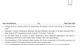
Parameters changing in Nozzle:, , Nozzle, , De Laval nozzle, showing approximate flow velocity, (v), together with the effect on temperature (T) and, pressure (p)
Page 8 :
flow velocity of fluid ,v, Mach number , M =, , Travelling velocity of sound, c, M = v/c, Sonic flow:, , When the fluid flow velocity in an orifice is equal to the, traveling velocity of sound in the fluid under this condition, the, flow is called a sonic flow., Subsonic flow:, , The speed of a subsonic flow of gas will increase if the pipe, carrying it narrows because the mass flow rate is constant., , (Mach number < 1.0 ), Choked flow:, , The gas flow through a de Laval nozzle, is isentropic (gas entropy is nearly constant). In a, subsonic flow sound will propagate through the gas. At, the "throat", where the cross-sectional area is at its, minimum, the gas velocity locally becomes sonic (Mach, number = 1.0), a condition called choked flow., Supersonic flow:, As the nozzle cross-sectional area increases, the gas, begins to expand and the gas flow increases to, supersonic velocities where a sound wave will not, propagate backward through the gas as viewed in the, frame of reference of the nozzle (Mach number > 1.0).
Page 9 :
Shapes of nozzles, , 1. At subsonic speeds (Ma<1) a decrease in the area, increases the speed of flow., 2. In supersonic flows (Ma>1), the effect of area, changes are different., , Significance of Mach number –, •, , •, •, , If the Mach number is less than one, flow is subsonic,, and the nozzle is convergent., If Mach number is equal to one, flow is sonic., If Mach number is greater than one, flow is, supersonic and the nozzle is divergent.
Page 10 :
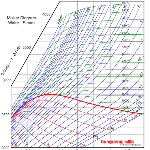
Nozzle efficiency:, It is the ratio of useful heat drop to the isentropic heat drop. It, is denoted by K, K = Useful Heat Drop / Isentropic Heat Drop, , How were we finding Useful heat drop &, isentropic heat drop, so let’s discuss some given, useful points for finding nozzle efficiency?, When the steam flows through a nozzle, some loss in its, enthalpy or total heat takes place due to friction between the, nozzle surface and the flowing steam. This can be best, understood with the help of h-s diagram or Mollier chart, as, shown in Figure:, , Process of h-s Diagram:, , Process of h-s Diagram – nozzle efficiency, , 1. First of all, locate the point A for the initial, conditions of the steam. It is a point, where, the saturation line meets the initial pressure, (P1) line., 2. Now draw a vertical line through A to meet, the final pressure (P2) line. This is done as
Page 11 :
the flow through the nozzle is isentropic,, which is expressed by a vertical line AB. The, heat drop (h1 – h2) is known as the isentropic, heat drop., 3. Due to friction in the nozzle the actual heat, drop in the steam will be less than (h1- h2)., Let this heat drop be shown as AC instead of, AB., 4. As the expansion of steam ends at the, pressure P2, therefore a final condition of, steam is obtained by drawing a horizontal line, through C to meet the final pressure (P2) Line, at B’., 5. Now the actual expansion of steam in the, nozzle is expressed by the curve AB’, (adiabatic expansion) instead of AB, (isentropic expansion). The actual heat drop, (h1 – h3) is known as a useful heat drop., The efficiency of a nozzle generally varies from, 0.85 to 0.95., , Factors affecting nozzle efficiency, 1. Material of the nozzle., 2. Size and shape of the nozzle., 3. Finish of the nozzle., 4. Angle of divergence., 5. Nature of the fluid and its state,, 6. Friction., 7. Fluid velocity., 8. Turbulence in the flow passages
Page 12 :
Selection Criteria of nozzle., Situation first: It is used when the backpressure is, equal or more than the critical pressure ratio. It, is also used for non – compressible fluids., Convergent nozzle: Cross-sectional area is, decreased continuously from entrance to exit., Situation second: When back pressure is less than, the critical pressure divergent nozzle is used., Divergent nozzle: Cross-sectional area is increases, continuously from entrance to exit., Situation third: When back pressure is less than, the critical pressure convergent-divergent nozzle, is used., Convergent and Divergent nozzle: Cross-sectional, area of nozzle first continuously decreases and, then increases from entrance to exit., Application Of Steam Nozzle :, •, , Steam and Gas turbine –, , •, , Jet Engine, , •, , Rocket Motors-, , •, , •, , It is used to measure the discharge of fluid.e.g. Venturimeter, Injectors for pumping feed water to boilers.
Page 13 :
•, , •, , •, , The supersonic gas turbine engine: for the air, intake when the air requirement of the engine, is high., Rockets: for providing sufficient thrust to move, upwards., For removing air from the condenser using the, injector., , •, , Spray painting, , •, , Steam jet refrigeration system, , ----xx-----
Page 14 :
Unit 4.2, Steam turbine – classification of turbines,, Construction and working of impulse, and reaction turbine., Unit 4.3, Compounding of turbines and its types., Regenerative feed heating,, Bleeding of steam,, Governing and its types., Losses in steam turbines., , Introduction to Steam Turbines:, , Steam turbine
Page 15 :
A steam turbine is a form of prime mover in which the, energy available with high-pressure steam is converted, into mechanical power directly in the form of rotary, motion., The operation of steam turbine depends on the dynamic, action of steam expanded through nozzle., The steam turbine develops power from the change of, momentum of steam jet while passing over a smooth, vane or blade (Fig. 4.3)., , High-pressure steam from boiler is expanded in a nozzle, (Fig. 4.4). It is well known that nozzles are used to, convert pressure energy into kinetic energy., The enthalpy of steam is first converted into kinetic, energy in the nozzle or blade passage.
Page 16 :
The high-velocity steam produced by the nozzle flows, over the curved vane or curved blade, thereby gaining a, change in momentum., , Figure 4.5 is the projected view of a set of two nozzles, mounted by the side of a rotor mounted with a number, of blades. They are separated by a gap of 5 mm. The, flow of steam and the motion of blades have been, shown in Fig. 4.5., , The force produced by the change in momentum is, known as impulsive force which tries to push the blade, in forward direction, but the blades are not free to move., They are fixed on wheel or rotor. If a certain number of, blades are fixed on the periphery of the rotor and the
Page 17 :
steam jet is allowed to pass through it, the rotor will start, rotating., The rotor of the turbine is mounted on the shaft and, supported by bearing. Thus, the shaft starts rotating, (Fig. 4.6). A steam turbine is mainly used to drive, electrical generator in thermal power plants to generate, electrical energy., Parts of Steam Turbine:, The main parts of steam turbines are – nozzles, wheel, or rotor, vanes or blades, and casing., , i., , Nozzle:, , A high-pressure steam from the boiler enters into the, convergent divergent nozzle attached with the casing of, the turbine. The expansion of steam takes place through, the nozzle. A high-pressure and relatively low-velocity
Page 18 :
steam is available at the entrance of the nozzle. The, pressure at the exit of the nozzle is found very less due, to the expansion of steam. A high-velocity jet of steam is, produced at the exit section., i., , Rotor:, , It is a wheel mounted on a shaft. The rotor is mounted, on the bearing to have smooth and effective rotation., The blades are erected on the entire circumference of, the rotor. A rotor fitted with blades has been shown in, Fig. 4.7. In actual practice the blades are shrouded from, the top which has not been shown in the figure. It is, provided to keep the blades in their position without, deflecting them by the thrush given by high-pressure, steam and also the steam flowing in blade channel will, not be allowed to leave from the top due to centrifugal, fugal action., , iii. Blades:, On the entire periphery of the rotor, a large number of, blades are erected. Two conjugative blades form a, blade passage through which a jet of steam at high
Page 19 :
kinetic energy impinges on the blade surface into the, blade passage., A change in the momentum is experienced by the flow, of steam, which results in tangential force on the blade., The blade starts moving, but it is not free to move, because it is fixed on the rotor. So, the rotor starts, rotating. The surface of the blades is made very smooth, to minimize the blade friction loss (Fig. 4.8)., , iv. Casing of Turbine:, It is an enclosure which covers the rotor as well as, blades assembly. The nozzle is attached with casing., The casing is kept separate from the rotor by placing, some kind of packing or oil seal to run the shaft freely, and to prevent leakage., , Classification of Steam Turbine:, The classification of steam turbine is given in Fig. 4.9., The most important common divisions are with respect, to the dynamic action of the steam. A steam turbine is, mostly a case of axial flow.
Page 20 :
Based on exhaust condition:, ▪, ▪, ▪, ▪, ▪, ▪, , Condensing, Non condensing, Automatic extraction, Mixed pressure, Regenerative extraction, Reheat, , Based on stage design:, ▪, ▪, , Impulse, Reaction, , Based on steam flow:, ▪, ▪, ▪, , Axial flow, Radial flow, Mixed flow
Page 21 :
Based on stages:, ▪, ▪, , Single stage, Multi stage, , Based on casing or shaft design:, ▪, ▪, ▪, , Single casing, Tandem casing (two or more), Cross compound, , Based on exhaust stages in parallel:, ▪, ▪, , Double flow, Triple flow, , Based on type of drive:, ▪, ▪, , Generator, Mechanical drive, , I., , Impulse Turbine:, , Simple Impulse Turbine (De Laval Turbine):, A simple impulse turbine or single-stage impulse turbine, is suitable for low-pressure steam., An impulse turbine is a type of turbine in which the, pressure drop takes place only in the nozzle., The pressure remains constant throughout while flowing, over the moving blades. In this case, the high-pressure, steam is initially expanded in a nozzle or a set of
Page 22 :
nozzles which is placed by the side of rotor leaving, some gap of about 5-6 mm., As the steam flows through the nozzle, pressure falls, from steam chest pressure to condenser pressure in the, case of condensing type or atmospheric pressure in the, case of non-condensing type of plant., Due to pressure drop, a high velocity is obtained at the, outlet of the nozzle. The steam at this high kinetic, energy flows over the blade channel and then it is, discharged from the turbine., It is evident that if the initial pressure of steam is very, high, the kinetic energy obtained at the exit of the nozzle, is very high and hence the velocity of steam leaving the, moving blade is high in proportion to the maximum, velocity of steam when leaving nozzle. The loss of, kinetic energy at the exit is known as leaving loss. The, velocity of steam at the exit is known as lost velocity., In the beginning, the simplest form of turbine was, developed which was known as De Laval turbine. In this, turbine, the exit velocity or leaving velocity or lost, velocity was about 4-5% of the nozzle outlet velocity. In, addition to this, since all the kinetic energy was to be, utilized by one row of moving blade only, the revolution, of the rotor could be expected about 20,000 rpm., Such a high revolution was rather unmanageable with, balancing point of view. However, the rotor speed could, be reduced by the method of compounding. The, compounding of turbine was done to reduce the rotor, speed.
Page 23 :
Figure 4.10(a) shows the diagrammatic representation, of a simple impulse turbine in which large number of, blades is fitted on the circumference of a wheel, called, rotor., , Figures 4.10(a) and 4.10(b) show the representation of, an impulse turbine. The top portion shows the nozzle, and blades, and the lower portion shows the variation of, the pressure and velocity of steam as it flows over the, nozzle as well as blade channel. Since the expansion of, steam takes place only in the nozzle, the pressure drop, is represented by the curve PQ by dotted line., As there is no change in the pressure of steam while, passing over the row of blade, the pressure is shown by
Page 24 :
the horizontal line QR. Since the velocity of steam, increases due to expansion in the nozzle, an increase in, velocity is represented by AB by a full line. As some of, the kinetic energy is utilized as it flows over the moving, blade, the steam comes out at less velocity represented, by the line BC., , ii. Compounded Steam Turbines:, Due to advancement in technological ability, the trend is, to generate steam at high pressure and temperature, as, high as 100-150 bar pressure and about 550°C super, heat., For obtaining maximum thermal efficiency, the total, pressure drop from boiler to condenser pressure must, be completely converted into kinetic energy., If the entire pressure drop from high to low pressure, takes place only in one set of nozzles, then the turbine, rotor rotates at a very high speed in order of about, 20,000 rpm. Such a high revolution of turbine rotor is not, useful for practical purposes. It poses a number of, technical problems such as structural failure due to high, centrifugal stress developed, increase in vibration,, excessive noise produced, and overheating of bearings., The high speed will require a reduction gear to couple, with generator. In addition to this, the lost velocity at the, discharge point is very high. It is about 5-6% of the initial, velocity. This gives rise to a great loss. Therefore, the, expansion of steam is carried out in several stages
Page 25 :
instead of a single stage. The successful utilization of, total available energy can be done by compounding., The different types of compounded steam turbines are, as follows:, , (a) Velocity-compounded turbines, (b) Pressure-compounded turbines, (c) Pressure-and-velocity-compounded turbines, , a. Velocity-Compounded Turbines (Curtis):, A velocity-compounded turbine is shown in Fig. 4.11. In, this case there is one set of nozzles and two or more, rows of moving blades arranged in series. In between, two rows of moving blades, one set of guide blades, which is fixed and hung from the casing of turbine is, arranged in a suitable manner.
Page 26 :
The placement of the blades in fixed row is just the, reverse of moving blades rows. The steam is expanded, in nozzle from boiler pressure down to condenser, pressure. The high-velocity jet of steam coming out from, nozzle is passed onto the first row of moving blades, where it produces a change of momentum., The kinetic energy gained in nozzle is utilized in the, stages of moving rows and finally the steam is, exhausted from the first row at comparatively less kinetic, energy but in reverse direction. The steam then enters, the first row of fixed blades and is redirected by, changing direction to the second row of moving. This, way the expansion is continued till total kinetic energy is, fully absorbed. A turbine working on this principle is, known as velocity-compounded steam turbine.
Page 27 :
Steam loose its velocity every time when it passes, through the moving blades. So, steam leaves the turbine, with a low velocity. So, we can see that the steam's, pressure can only drop at nozzle and further pressure, drop occurs either in the moving or fixed blades. Velocity, and pressure curves on a base represent the axis of the, turbine. This method is used in CURTIS TURBINE., Advantages velocity compounded steam turbine:, 1. This arrangement needs small space., 2. This is very reliable and easy to operate., 3. Initial cost is low for this arrangement., 4. Since nozzle's steam is considerable, the turbine, does not need to work in high pressure and turbines, structure need not be very strong., , Disadvantages velocity compounded steam turbine:, 1. Friction loss is high due to high velocity of steam of, nozzle., 2. Its efficiency is low. Because the ratio of blade, velocity and steam velocity is not optimum., 3. First, row is developed maximum power in this, system. Later rows are developed very small power, rather than first row. But fabrication and cost of materials, will be same in all rows.
Page 28 :
b. Pressure-Compounded Turbines (Rateau):, Pressure-compounded impulse turbine is one in which a, number of simple impulse turbines are arranged in, series and placed on a common shaft., In this case, a row of fixed nozzles is placed at the entry, of each row of moving blades, i.e., this comprises, alternate rows of fixed nozzles and moving row of, blades in series., The total pressure drop from high pressure to exhaust, pressure is split into series of smaller pressure drop to, take place in different stages in series. Each set, combining one row of fixed and one row of moving blade, is known as one stage., High-pressure steam is expanded in the first row of fixed, nozzles of the first stage with a small pressure drop., Due to small pressure drop, less kinetic energy is, available at the exit of first row of fixed nozzles. The, steam with small kinetic energy enters to the first row of, moving blades where it undergoes a change of, momentum and the kinetic energy is absorbed. The, pressure remains the same while flowing in the first row, of moving blades., The steam from first stage then enters to the second, stage where there is further small pressure drop and, increase in the kinetic energy which is again absorbed., This will continue till the steam pressure becomes equal, to the exhaust pressure.
Page 29 :
Nozzle….small pressure drop and rise in velocity, Moving blade …..pressure remains almost same and, drop in velocity as it imparts its, energy to blades., c. Pressure-and-Velocity-Compounded Turbines:, Such turbines are the combination of pressure and, velocity compounding., If the pressure range is very large, this arrangement is, very much suitable., As we know, a two-row velocity-compounded turbine is, more efficient than a three-stage velocity-compounded, turbine. But the construction of two-row velocity-
Page 30 :
compounded turbine possesses some difficulties as it, increases the velocity per blade., Hence, the total pressure drop of steam from boiler, pressure to exhaust pressure would split up in two and, three steps, as done in pressure compounding, and the, kinetic energy gained in each step is absorbed, completely in two moving wheels before the next, pressure drop occurs., In a two-step pressure-and- velocity-compounded, turbine, the first pressure drop occurs in the first set of, nozzles, the gain in kinetic energy is utilized completely, in two rows of moving blades before the second, pressure drop occurs in second set of nozzles, and the, kinetic energy gained is again utilized in two rows of, moving blades successively.
Page 31 :
A CURTIS TURBINE is an example of pressure velocity, compounded method. Pressure and velocity curve for, this turbine is shown in fig.
Page 32 :
II. Reaction Turbine:, In principle, pure reaction turbine has no meaning with, steam as a working fluid. It is actually with a joint, application of impulse and reaction., In this type of turbine, the high-pressure steam is not, expanded initially in the nozzle only, as in the case of, impulse turbine, but the expansion of steam takes place, in moving blade row also., The moving blade also acts as nozzle. The shape of the, blade is so well-designed (known as aerofoil section, blade) that the blade channel formed between two, consecutive blades acts as a nozzle and forms a narrow, passage at the exit. At the exit of the nozzle, steam will, possess both pressure as well as kinetic energy., The steam which possesses some pressure energy gets, further expanded while passing over in blade channel, and hence further increase of kinetic energy is obtained., Hence, a gradual pressure drop takes place, continuously over the nozzle and moving blades., The increase in the velocity of steam, flowing over the blade passage develops an, opposite reaction., The opposite reaction force acting on the, blade forms a propulsive force. In addition, to this propulsive force, there is also a, change in momentum due to change in, velocity. This causes an impulsive force on, the moving blade. Thus, the net force on
Page 33 :
moving blade in reaction turbine is the, resultant of reaction force and the impulsive, force as shown by the force diagram shown, in Fig. 4.12., Aerofoil shape, Space at exit of, blade is less as, compared to, inlet., , Figure 4.13 shows a four-stage reaction turbine. The, actual reaction turbine (Fig. 4.13), also called impulse, reaction turbine, consists of a number of rows of moving, blades fitted on a single rotor. The fixed blade ring is, hung from the casing of the turbine between the two, rows of moving blade. The blade of fixed row is placed, just reverse to the blade of moving row. The highpressure steam passing in the first row of fixed blade, undergoes a small drop in pressure causing the, increase of velocity of the steam.
Page 34 :
It then enters the first row of moving blades where it, suffers further drop in pressure and the kinetic energy is, converted into mechanical energy in terms of the, rotation of rotors. Thus, the velocity of steam decreases., This continues in the further rows of moving and fixed, blades till the pressure of steam is completely reduced., The variation of pressure and velocity has been shown, in Fig. 4.14.
Page 35 :
Comparison of Impulse and Reaction Turbine:, Impulse Turbine:, i. Pressure drop takes place only in the nozzle and not in, the moving blade. The pressure remains constant in the, moving blade row., ii. The area of blade channel at entrance and exit is, same., iii. Symmetrical profile type blades are used in impulse, turbine which provides a uniform section. Impulse, turbine may be either partial admission or full admission., iv. This occupies less space for the same power.
Page 36 :
v. Not much power can be developed., vi. Efficiency is found low., vii. Suitable for small power generation., viii. High rotor speed requires compounding of turbine., Reaction Turbine:, i. Pressure drop takes place in the fixed blade (nozzle), as well as in the moving blade row also., ii. The area of blade channel at the exit is made narrow., It is of convergent type., iii. Aerofoil types of blades are used in reaction turbine., Reaction turbine is always full admission turbine., iv. This occupies more space for the same power., v. Much power can be developed., vi. High efficiency can be achieved., Vii. Suitable for medium and high power generation., viii. The speed is relatively low and hence no, compounding is required., , Advantages of Steam Turbine over Steam Engines:, (a) The thermal efficiency of a steam turbine plant is, higher.
Page 37 :
(b) Steam turbines are highly simplified in construction, and operation., (c) Condensate can be directly used in boilers., (d) Vibration and noise are minimized., (e) Balancing of rotor can be done accurately., (f) Much higher speed is possible., (g) Steam turbines are suitable for the operation with, high-pressure steam., (h) They are well suited for large steam power plants., , REGENERATIVE FEED HEATING OR BLEEDING OF, STEEM:
Page 38 :
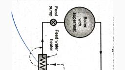
REGENERATIVE FEED HEATING, , Regenerative feed heating, where steam is drawn off, the turbine between stages to preheat the feed water., The process of draining steam from the certain section, of multistage turbine during its expansion and using this, steam for heating feed water supplied to boiler is known, as bleeding of steam and this process of heating feed, water is known as Regenerative feed heating., Feed heating system is of two types:, 2., , Cascade system: when the bleed steam does, not mix with feed water., In this system condensate of condenser, passes through the coil of the feed water, heater which is surrounded by bleed steam, from the turbine. Which heats the, condensate further and raises its, temperature., , 3., , Drain pump system: when the bleed steam mix, with feed water., In this case feed water and bleed steam, comes in direct contact as steam is directly, mixed with feed water. then supplied to boiler., , Advantages:
Page 39 :
1. The thermal efficiency is increases as heat, input decreases as high temp. water is feed, to the boiler., 2. Thermal stresses in the boiler are reduced., 3. Capacity of the condenser is reduced., 4. Reduced fuel consumption., Disadvantages: Cost of the plant increases., , STEAM TURBINE GOVERNING SYSTEM, Steam turbine governing system is a method, used to, maintain a constant steady speed of turbine., The importance of this method is, the turbine can, maintain a constant steady speed irrespective of, variation of its load. A turbine governor is provided for, this arrangement., The purpose of the governor is to supply steam into the, turbine in such a way that the turbine gives a constant, speed as far as possible under varying the load. So,, basically Steam turbine governing system is a, process where turbine maintains a steady output speed, irrespective of variation of load., The different types of steam turbine governor of are:, 1. Throttle Governing Of Steam Turbine, 2. Nozzle Control Governing Of Steam Turbine, 3. Bypass Governing Of Steam Turbine
Page 40 :
1. Throttle Governing Of Steam Turbine:Throttle Governing of steam Turbine is most popular and, easiest way to control the turbine speed., When steam turbine controls its output speed by varying, the quantity of steam entering the turbine is called, Throttle Governing. It is also known as Servomotor, methods., In this system, a centrifugal governor is driven from the, main shaft of turbine by belt or gear arrangement., A control valve is used to control the direction of oil flow, which supplied by the pipe AA or BB., The servomotor or relay valve has a piston which moves, towards left or right depending upon the pressure of oil, flow through the pipes AA or BB., This cylinder has connected a needle which moves, inside the nozzle., When the turbine is running at normal speed, everything, in the turbine such as such control valve, servomotor,, piston position, fly balls of centrifugal governor will be in, their normal position as shown in the figure. The mouth, of both pipes AA or BB is closed into the control valves.
Page 41 :
P, , Assume that the turbine's load increases. It will, decrease its speed which will decrease the centrifugal, force of the turbine. Now fly balls of the governor will, come down thus decreasing their amplitude. These fly, balls also bring down the sleeve. The sleeve is, connected to a control valve rod through a lever pivoted, on the fulcrum. This down word sleeve will raise the, control valve rod. Now oil is coming from the from the oil, sump, pumped by gear pump is just stay at the mounts, of both pipes AA or BB which are closed by the two, wings of control valves. So, raise of control valve rod will
Page 42 :
open the mouth of the pipe AA but BB is still closed., Now the oil pressure is coming from the pipe AA. This, will rush from the control valve which will move the right, side of the piston. As a result, the steams flow rate into, the turbine increases which will bring the speed of the, turbine to the normal range. When speed of the turbine, will come to its normal range, fly balls will come into its, normal position. Now, sleeve and control valve rod will, back to its normal position.
Page 43 :
2. Nozzle Control Governing Of Steam Turbine:It is another interesting method by which turbine's speed, can be controlled., Nozzle control governing of steam turbine is basically, used for part load condition., Some set of nozzles are grouped together (may be two,, three or more groups) and each group of the nozzle is, supplied steam controlled by valves., Every valve is closed by the corresponding set of, nozzle. Steam's flow rate is also controlled by these, nozzles., Actually, nozzle control governing is restricted to the first, stage of turbine whereas the subsequent nozzle area in, other stage remains constant. According to the load, demand, some nozzles are in active and other inactive, position., Suppose turbine holds ten numbers of nozzles. If the, load demand is reduced by 50% then five numbers of, nozzles are in open condition and rest is closed. This, method is suitable for SIMPLE IMPULSE TURBINE. It is, a process where rate of steam flow is regulated, depending on the opening and closing of set of nozzles, rather than regulating its pressure., In nozzle governing the flow rate of steam is regulated, by opening and shutting of sets of nozzles rather than, regulating its pressure. In this method groups of two,, three or more nozzles form a set and each set is, controlled by a separate valve. The actuation of, individual valve closes the corresponding set of nozzle, thereby controlling the flow rate.
Page 44 :
In actual turbine, nozzle governing is applied only to the, first stage whereas the subsequent stages remain, unaffected. Since no regulation to the pressure is, applied, the advantage of this method lies in the, exploitation of full boiler pressure and temperature., Figure 2 shows the mechanism of nozzle governing, applied to steam turbines., As shown in the figure the three sets of nozzles are, controlled by means of three separate valves., , Nozzle Control Governing
Page 45 :
3. Bypass Governing Of Steam Turbine:Occasionally the turbine is overloaded for short, durations. During such operation, bypass valves are, opened and fresh steam is introduced into the later, stages of the turbine., This generates more energy to satisfy the increased, load., The schematic of bypass governing is as shown in, figure3., , Bypass Governing
Page 46 :
Bypass governing of steam turbines a method where a, bypass line is provided for the steam., Especially this is used when turbine is running in, overloaded condition., The bypass line is provided for passing the steam from, first stage nozzle box into a later stage where work, output increase., This bypass steam is automatically regulated by the lift, of valve which is under the control of the speed of the, governor for all loads within its range., Bypass valve is open to release the fresh stem into the, later stage of the turbine. In the later stage output, work, is increased and the efficiency is low due to the throttle, effect., , Losses in Steam Turbine:, Practically turbine's work done is much less than, isentropic heat drop of the steam used. Because some, internal losses occurred at the time of its operation., These losses are directly affected by the turbines output, as well as its efficiency., When turbine works, some factors have reduced the, output of the turbine, known as the losses in steam, turbine or internal loss in the turbine., , 1. Nozzle Friction Loss :It is a very important loss for Impulse Turbine. When, steam passes through the nozzles, friction loss occurs
Page 47 :
and the formation of eddies. Friction occurs in the nozzle, due to the factor of nozzle efficiency and it is the ratio of, actual enthalpy drop to isentropic enthalpy drop.2. Blade, , Friction Loss:This loss is important for both Impulse and Reaction, turbine. Blade friction loss is due to the steam's gliding, over the blades and friction of the surface of the blades., The effect of turbine blades is considered as a blade, velocity coefficient. The relative velocity of steam is, reduced for this loss., , 3. Wheel Friction Loss :When steam passes through the rotating turbine wheel,, it produces some resistance on the turbine wheel. As a, result, it rotates in lower speed from its original speed. It, is the loss in both Impulse and Reaction turbine. The, total frictional loss is about 10% of total turbine loss., , 4. Losses due to mechanical friction :This loss is for turbine's bearing. Mechanical friction loss, is due to the friction between the shaft and wheel, bearing and also the regulating valve of the turbine. This, loss may be reduced by proper lubrication of the moving, parts of the turbine. This loss occurs both Impulse and, Reaction turbine., , 5. Losses due to leakage :Leakage loss is different in both Impulse and reaction, turbine. In Impulse turbine, leakage loss occurs between, the shaft, bearings, nozzles and stationary diaphragms., For Reaction turbine, it may occur at the blade tips. This, loss is due to the leakage of steam on each stage of the, turbine. Total leakage loss is about 1 to 2% of total, turbine loss.
Page 48 :
6. Residual Velocity loss :When kinetic energy of steam leaves from the turbine, wheel, it happens. Actually, steam leaves from the, turbine with some certain absolute velocity. That's why, steam loses some kinetic energy. Residual velocity loss, can be reduced by multistage turbines. This loss is, about 10 to 12% in a single stage turbine., , 7. Loss in regulating valves :Before entering the steam to the turbine, it passes, through the boilers stop and regulating valve. Steam, gets throttled in these regulating valves and as a result, steam pressure will be less than the boiler pressure at, the entry of turbine., , 8. Loss due to wetness of steam:This loss is due to the moisture present in the turbine., When steam passes through the lower stage of the, turbine, it becomes wet. At the lower stage, the velocity, of water and steam are different and will not form a, homogeneous mixture. That's why the velocity of water, particle is less than that of steam and water particle has, to be dragged with the steam and some part of kinetic, energy of steam is lost. This loss occurs both impulse, and reaction turbine., , 9. Radiation Loss:This loss mainly takes place due to the temperature, difference between turbine casing and its surrounding, atmosphere. This loss can be minimized by the heavily, insulated turbine. This loss is in also both impulse and, reaction turbine.
Page 49 :
10. Governing loss:It is the loss in both impulse and reaction turbine and, this loss is due to the throttling of the steam at the main, stop valve of the governor., -------xxx------