Page 1 :
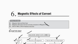
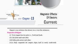
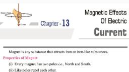
2, , MAGNETIC EFFECT OF CURRENT, , CHAPTER, , CONTENTS, , , , , , , , , , , , , , , , , , Magnetism, Types of magnets, Two Poles of a Magnet, Magnetic field, Earth magnetic field, Orested's experiment, Magnetic field due to current, carrying wire, Magnetic force, E M I, Electric Motor (D.C.Motor), Alternating Current (AC), Generator, , , , , , Earthing, Over-loading & ShortCircuiting, , Magnetism : The property due to which a, substance attracts iron pieces towards it, is, called magnetism., The substance having property of magnetism,, is called magnet., , TYPES OF MAGNETS, , , Properties : These have following two, properties., (i) Attractive property: They attract small iron, pieces towards them., (ii) Directive property: When suspended freely,, their ends would point in geographical north–, south direction. For this reason, the, suspended piece is called lode stone or, leading stone., Disadvantage : These have following two, , , demerits :, (i) They have irregular shape., (ii) They are weak., , Domestic electric circuits, , MAGNETISM, , , (A) Permanent (Natural & Artificial magnets), Natural magnets, Definition : Pieces of naturally occurring iron, ore lode–stone or magnetic or black iron, oxide (Fe2O3), are called natural magnets., , , , Artificial Magnets, , , Description : These magnets are made of, hard steel or special alloys. The substances of, these magnets have many small ‘atomic’, magnets. Ordinarily they are all oriented in, random directions (Fig.). Then the substance, is unmagnetised., , (a) Unmagnetised, S, , N, , Types of Magnets, (A) Permanent (Natural & Artificial magnets), (B) Temporary (Electromagnets), , (b) Magnetised., When such a piece is put in North–South, direction and hammered, the atomic magnets
Page 2 :
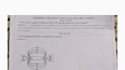
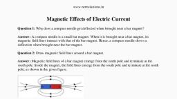
, , align themselves in the direction of the, earth’s field fig. They retain this alignment, and the piece becomes a magnet with North, (N) and (S) pole near ends. This magnet with, two poles, is called a magnetic dipole., Advantage : These have following two, , its ends only and not to its sides. It means that, , merits, , two ends point in north–south direction. The, , in magnets, centres of attraction are located, near ends only. These centres of attraction, near the ends of a magnet are called poles., When this magnet is freely suspended, the, , (a) They may be given desired regular shape., , pole near the end pointing towards North, , (b) They are strong., , (north–seeking end) is called North pole. The, , (B) Electromagnet, Electromagnets are based on the magnetic, effect of electric current. An electromagnet is, usually prepared by placing a soft iron core in, a solenoid, or by winding a large number of, turns of an insulated wire (generally the, insulated copper wire) on a cylindrical soft, iron core. An electromagnet shows magnetic, properties only as long as the electric current, flows, through, the, solenoid., Thus,, electromagnets are temporary magnets., Difference between electromagnet and, permanent magnet, Electromagnet :, Nature of magnetism : Temporary. An, electromagnet shows magnetism only as long, as current flows through it., Polarity : The polarity of an electromagnet, can be changed by reversing the direction of, the current., Strength : The strength of an electromagnet, can be increased or decreased by increasing, or decreasing the current., Permanent magnet (or Bar magnet) :, Nature of magnetism : Permanent (or bar), magnets show permanent magnetism., Polarity : Polarity of a permanent magnet, cannot be changed., Strength : The strength of a permanent, magnet cannot be changed., , pole near the end pointing towards South, (south–seeking end) is called South pole., , , Interaction between poles : The magnetic, poles exert forces on each other. Like pole, repel each other, i.e., one north pole will, repel another north pole or unlike poles, attract each other i.e., north pole attract south, pole., , MAGNETIC FIELD, Lines of Magnetic field (Magnetic lines of, force), , , Definition : A magnetic line of force, is a line, straight or curved, in the magnetic field of a, magnetic pole of magnetic dipole, such that, the tangent at any point of this line gives the, direction of the magnetic field at that point., , Properties of Magnetic Lines of Force, These have following properties :, , , They are always nearly normal to the surface, of magnet at every point., , N, , S, , TWO POLES OF A MAGNET, , , , Poles of a magnet : When ends of a magnet, are dipped in iron filings, the filings stick to, , They start from a north (positive) pole and, end at a south (negative) pole.
Page 3 :
, , , , , , Two lines of force do not intersect each, other., They tend to contract longitudinally, (longitudinal contraction)., They tend to expand laterally (lateral, repulsion) so as to exert lateral pressure on, neighboring lines., (The above two properties are similar to that, of a stretched rubber band)., The number of magnetic lines of force, passing normally per unit area about a point,, gives the intensity of the magnetic field at the, point., , ORESTED'S EXPERIMENT, , , , , Arrangement : A straight wire AB is, connected to a battery V and key K. The wire, is held horizontally over a magnetic needle., I, , S, , I, , B, , (a), I, , V, + –, , K, , Earth Magnetism : Earth behaves as a huge, , , this huge magnetism is given as the molten, charged metallic fluid giving rise to a current, flowing inside the core of the earth. This core, has a radius of about 3500 km (earth’s radius, is 6400 km)., Some Associated Terms, , 1. South Magnetic Pole (S) : It is near north, geographical pole N., 2. North Magnetic Pole (N) : It is near south, , S, , I, , A, , magnet (or a giant solenoid). The source of, , I, N, , I, , geographical pole S., , I, N, , A, , , , , , K, , I, , EARTH’S MAGNETIC FIELD, , , V, + –, , B, , (b), , Working : When key is closed, current flows, in the wire in the direction as shown. The, needle deflects one side. When key is taken, out and current in wire becomes zero, needle, returns back to its initial position (S – N). This, shows that a magnetic field is associated with, an electric current., When direction of current in wire is reversed,, direction of deflection of needle is also, reversed. If direction of current be kept same, and wire be put under the needle, direction of, deflection of needle again becomes reversed., , , , MAGNETIC FIELD DUE TO CURRENT, CARRYING WIRE, , Geographical, north, , , , N, S, , Magnetic, South, Geographical, equator, , N, Magnetic, north, , Magnetic, equator, S, , Geographical, south, , (A) Straight wire :, It means that when the current flows in a, straight wire, the magnetic field produced has, circular lines of force surrounding the wire,, having their centres at the wire as shown in, fig., , The, , plane, , of, , circular, , is, , perpendicular to the length of the wire. Their, direction is marked by arrows., , , , lines
Page 4 :
In case 2, curled fingers represents the, direction of the current in circular wire and, thumb represents the direction of the straight, magnetic lines of force. (Fig.), , Straight wire, Battery, , , B, , I, Current, , Current, , Fig. (a) Current straight, magnetic field, circular, (B) Circular coil :, , Right hand thumb rule for direction of, magnetic field., (C) Solenoid :, Definition : A solenoid is a straight, cylindrical core on which a large number of, turns of a insulated copper wire are wrapped., It is shown in fig., , Magnetic, field lines, , Magnetic fields, ., , fig, (b) Current circular, magnetic field straight, It means that when the current flows in a, circular wire (coil), the magnetic field, produced has straight lines of force near the, centre of the coil, as shown in figure. The, parallel lines are in a plane perpendicular to, the plane of the coil. Their direction is, marked by the arrows., Rule : The direction of the magnetic lines of, force is related with the direction of the, current by the right hand thumb rule., The rule states :, Curl the four fingers of the right hand on the, palm, keeping the thumb stretched out at right, angles. The thumb is straight and the fingers, are circular., In case 1. thumb represents the direction of, the current in the straight wire and curling of, fingers represents the direction of the circular, magnetic lines of force (fig.)., , , S, N, Solenoid carrying a current and polarity of its, face, , , , MAGNETIC FORCE, Force on a Current Carrying Wire due to, Magnetic Field :, Introduction : A current carrying conductor, produces a magnetic field around it. When it, is placed in a magnetic field, the two, magnetic fields interact. A force acts on the, conductor., A, , B, Y', , , , Y, , I, A', Force on a conductor, , i, , , B, , F, , Expression : It is found by calculation that if, the conductor of, length be carrying a, current I lying inside a magnetic field of, intensity B and making an angle with it, the, force acting on it is given by, F = I B sin
Page 5 :
Fleming’s Left–Hand Rule :, , , F, , , , 90°, 90°, , B, , i, , Fleming’s left–hand rule is used to find out, the direction of motion of a current–carrying, conductor when placed in a magnetic field., This rule states as follows., Stretch out the thumb, the forefinger, and the, second (middle) finger of the left hand so that, these are at right angles to each other. If the, forefinger gives the direction of the magnetic, field (N to S), the second (middle) finger the, direction of current (+ to –), then the thumb, gives the direction of the force acting on the, conductor., Since the conductor will move in the, direction of the force acting on it hence the, thumb gives the direction of motion of the, conductor., Force on a moving charge, A current–carrying conductor (e.g., a wire), experiences a force when placed in a, magnetic field. The current represents a, collection of charged particles in motion., Therefore, each moving charged particle in a, magnetic field will also experience a force,, called Lorenz force., The direction of the force experienced by a, positive charge is the same as that on the current, and is given by Fleming’s left-hand rule., The force, experienced by a current carrying, conductor in a magnetic field is given by,, F=BI, If Q is the charge passed through the, conductor in time t, we can write, I=, , , Q, t, , The above relationships, when combined, give,, F=, , BQ, = BQv, t, , where v is the velocity of the charged particle, perpendicular to the direction of the field, , EMI (ELECTROMAGNETIC INDUCTION), , , Introduction : Whenever magnetic flux, linked with a closed loop changes, an electric, current is produced in the loop (a, galvanometer connected with closed loop,, shows a deflection). The current lasts only so, long as the flux is changing., This phenomenon is called electromagnetic, induction. The electric current produced, is, called induced current. The e.m.f. which, produces this current, is called induced e.m.f., , ELECTRIC MOTOR (D.C. MOTOR), (A) Principle : It works on the principle of, motion of a current carrying conductor in a, magnetic field, according to Fleming’s Left, Hand Rule., It is a device which converts electrical energy, into mechanical energy of rotation., (B) Diagram :, , B, , C, Field, , N, , S, D, , A, B1, , R1, , R2, , B2, , (a), , C, , B, Field, , N, , S, A, , D, B1, , R2, , R1, , (b), Figure : DC Motor, , B2
Page 6 :
(C)Construction : It has four mains parts,, named below., A field magnet having concave magnetic, poles N–S, which provides a strong magnetic, field., An armature, which is moving part of the, motor. It has two parts :, (i) Laminated shaft X–Y., (ii) Copper coil ABCD wrapped on end X of, the shaft inside the field., A pair of metallic split rings R1 and R2, (commutator)., A pair of metallic carbon brushes B1 and B2., (D)Working : A direct current (D.C.) source is, connected between metallic brushes B1 and, B2. When current passes through the coil, it, flows in arms CB and AD in a direction, perpendicular to the magnetic field. Equal, and opposite forces act on these arms (in a, direction according to Fleming’s Left hand, Rule) and they form a couple. The coil rotates, in clockwise direction (Fig.). After half, rotation, split parts of ring change brushes., Current becomes reverse in the arms but, couple acts in same direction as before. The, coil continues rotating the shaft on which it is, wrapped. Thus, rotatory motion (motor, action) becomes available., The rotation is not smooth with single coil. It, is made smooth by increasing number of coils, (multiphase motor) or preferably by having a, continuous winding., , , , compared to those operated on direct current, (DC)., Alternating current (AC) can be controlled by, a choke coil at very low energy loss. On the, other hand, direct current (DC) can be, controlled only by ohmic resistances at, relatively much higher energy loss., , GENERATOR, AC Generator, , , Construction of an ac generator : It consists, of a rectangular coil of insulated copper wire., This coil is placed in a magnetic field, between the poles of a strong permanent, horseshoe magnet. This magnet is known as, the field magnet. In actual practice, a large, number of turns of the insulated copper wire, are suitably wound on an iron core called, armature., , B, , C, , A, , D, , R1, , P, B1, , R2, , B2, , Q, , (a), , ALTERNATING CURRENT (AC), The electric current which changes its, direction (or polarity) after a certain fixed, interval of time is called alternating current or, AC. Thus, in AC, the polarity (+ or –) is not, fixed. The electricity supplied to our homes, and industry in our country is alternating, current (AC)., Advantages of the alternating current (AC) :, The alternating current (AC) has the, following advantages., The alternating current (AC) can be, transmitted over long distances without much, loss of energy and at low rate of transmission., The alternating current (AC) operated, machines such as electric fan, electric motor, etc., are more durable and convenient as, , S, , Field, , N, , C, , B, S, , Field, , N, , A, , D, , R1, , P, B1, Q, , B2, (b), , R2
Page 7 :
The two free ends of the coil are connected to, the two slip rings R1 and R2. Current, , DC generator, A DC generator stands for direct current, electric generator. A DC generator produces, direct current. A DC generator is also called, DC dynamo. A simple DC generator is shown, in fig., , generated in the coil is taken out through the, two carbon brushes B1 and B2 pressed lightly, against the slip rings., , Working of an AC generator : Let the coil, ABCD be initially in the horizontal position,, and is rotated in the anticlockwise direction., When the coil is rotated anticlockwise, the, arm AB moves downwards and the arm CD, moves upwards. The coil during this, movement cuts the magnetic lines of force,, and produces induced current in the coil., According to the Fleming’s right–hand rule,, during this downward motion of the arm AB,, the induced current flows from B to A in the, arm AB, and from D to C in the arm CD. The, current so produced is taken out through the, two slip rings, and the carbon brushes., After half the rotation (after rotating through, 180º), the arms of the coil interchange their, position; the arm AB becomes the right arm, and the arm CD becomes the left arm. Then,, the arm CD starts moving downwards and the, arm AB upwards. During this half–rotation,, the induced current flows from C to D in the, arm CD, and from A to B in the arm AB. The, two slip rings also rotate with the coil. As a, result, their polarities (+ and – poles) keep, changing at every half–rotation., The current which changes its polarity after, regular intervals of time is called alternating, current (AC). So, this electric generator, produces alternating current (AC)., Frequency of the alternating current :, Alternating current (AC) so produced has a, definite frequency. This frequency is equal to, half the number of times the polarity changes, in one second. In our country, the frequency, of the alternating current supplied by the, power generation units is 50 cycles per, second (or Hz). This means, the alternating, current (AC) produced in our country changes, polarity 100times in one second., , , , B, , C, Field, , N, , S, D, , A, B1, , R1, , R2, , Q, , P, , C, , B, Field, , N, , S, A, , D, B1, P, , , B2, , R2, , R1, , B2, Q, , Construction of a DC generator : A simple, DC generator consists of a coil of insulated, copper wire. The coil is placed between the, two poles of a strong horseshoe magnet. In, actual practice, a large number of turns of the, insulated copper wire are wound on a soft, iron core., The two ends of the coil are connected to the, two halves of a split ring (R1, R2 called, commutator). Two carbon brushes press, against the two half–rings lightly. The current, is taken out through the brushes B1 and B2., , , Working, , of a DC generator : Let the coil, ABCD be initially in the horizontal position,, and be rotated anticlockwise. When the coil is, rotated anticlockwise, the arm AB moves, downwards and the arm CD moves upwards.
Page 8 :
The coil during this motion cuts the magnetic, lines of force and an induced current is, produced in the coil. According to Fleming’s, right hand rule, during the downward motion, of the arm AB, the induced current flows, from B to A in the arm AB, and from D to C, in the arm CD. The current so produced is, taken out through the two half–split rings, and, the carbon brushes., After half the rotation (rotation through 180º),, the arms of the coil interchanged their, positions; the arm AB comes to right and the, arm CD to the left. Then the arm CD starts, moving downwards, and the arm AB, upwards. During this half–rotation, the, induced current flows from C to D in the arm, CD, and from A to B in the arm AB., The two half–split rings (R1 and R2) rotate, with the coil and touch the two carbon, brushed (B1, B2) one by one. As a result, each, carbon brush continues to have the same, polarity, (+ or –). The brush B2 always, remains positive (+) terminal, and the brush, B1 remains negative (–) terminal. The current, , , so produced is called direct current (DC)., DC generator differ from an AC generator, : The basic design of AC and DC generators, is similar. The two generators differ only in, the design of slip rings at the ends of the coil, wire. An AC generator use two full rings, called slip rings, one at each end of the coil, wire, while an DC generator has two half–, rings (called split rings) of a commutator., , DOMESTIC ELECTRIC CIRCUITS, (A) Main board :, It is provided outside the building under a, covered place (varandah or poarch). It, contains the meter (energy–meter) and the, main switch., From the street electric pole a thick rubber, insulated cord reaches the main board. It, contains two thick copper or aluminium, wires, one covered with red and the other, covered with black (or brown) plastic, , covering., Main board, Live wires, From electric, pole, , Meter, , L Live, , 2146, kwh, , Main board, F, , Neutral, N, , L (Red), To inside, N (Black) building, , E, E, (copper), , P, , They from the live line wire (L) and neutral, line wire (N) respectively. Live line has a, potential of 220V whereas the neutral wire, has zero potential (with respect to the earth)., They enter the main board and are connected, to the meter., Wiring ahead is provided by the house owner, himself. These wires are also red and black, plastic covered. From the meter the wires, enter the main switch. In the main switch, a, fuse F is provided in the live wire., A third wire is a thick bare wire of copper,, called earth wire E. It is connected to an, earth connection which consists of a thick, copper plate P buried deep inside the moist, earth., (B) Inside the building :, It is a well known fact that inside the house,, connections to all the devices are made in, parallel, each having independent switch and, fuse (if necessary). Thus, whenever some, fault occurs in circuit of one particular device, in one room, devices in other rooms do not, suffer., L, N, E, S1, , B, , S2, F, , S3, , R, , P, , E, L, N, , S, A, A, , F
Page 9 :
As shown in fig. connection to low power, devices like bulb B and fan F are made with, lines N and L only, putting switch in line L., For devices of more power and with whom, the body remains in contact (like electric, press or refrigerator), we use connections, through a 3 pin plug–socket (show in fig. b), system., A three pin plug P and three pin socket S are, shown in diagram. The three points of the, socket are connected to the three lines as, shown in diagram. (fig. b) A fuse F is also, introduced to avoid damage to the appliance., The three pin plug uses a three wire cord, which has three plastic wires inside a single, rubber insulating cover. The wire are, coloured red, black and green to serve an, extension of live, neutral and earth wires for, the appliance. The three wires are connected, to the three holes in the socket as shown in, diagram. When the plug is inserted in the, socket, proper lines become connected to the, appliance., (C) Function of earth wire :, Due to long use some covered wires inside, the appliance may become bare and make, contact with metallic body of the appliance., In such a case the appliance gives a shock if, not earthed. The earth wire keeps the, potential of the appliance zero and shock is, avoided., , EARTHING , OVERLOADING &, SHORT CIRCUITS, Earthing, Definition : Connecting the metallic body of, a high powered electrical appliance (e.g., electric iron, refrigerator, oven, etc.) to the, earth wire of domestic circuit, is called, ‘earthing’., E, , L, N, Cable, (Red) L, , N (Black), E, (Green), , E, L, N, (c) Inside the plug, , In three pin plug, has three pins forming a, triangle. The upper pin is thicker than the two, lower pins. (fig.) The pins are connected, inside the body of the plug to the three, different coloured wires of a three–cored,, wire cable [Fig.]. The colour code of the, wires is green (Earth–E), Red (Live–L),, Black or Brown (Neutral–N)., Benefits : Due to wear and tear with long, use, the live wire inside the appliance, becomes bare (uncovered) and touches the, body of the applicance. This contact raises the, potential of the body to the huge potential of, the live wire. If we operate that appliance, with bare foot, we will be getting a severe, shock., If the appliance is earthed, its body potential, remains zero due to contact with the earth., Nothing is felt when such an appliance is, operated., We may conclude that we save ourselves, from severe electric shocks, by earthing our, electrical appliances., Over–Loading and Short–Circuiting, The current exceeds the limit under two, situations., (i) over–loading, (ii) short–circuiting, They are discussed ahead., Over–Loading : When high powered electric, appliances like refrigerator, airconditioner, and electric iron are switched on, simultaneously, total current through main, wire may exceed the tolerance limit causing, damage and fire. This situation causes over–, loading., Short–Circuiting : Due to long use wear and, tear or defective insulating material, the live, and the neutral wires may become bare at, some points and come in direct contact. Due, to zero resistance, a large current is produced, and a huge sparking is caused at the point of, contact. It may cause damages and fire. This, situation is called short–circuiting., ,
Page 10 :
Electric Fuse, , , , , Introduction : It is a small, simple and cheap, but very useful electric appliance used in, domestic electric circuits., Working : Whenever there is sudden voltage, rise in mains or “over–loading” or short–, circuiting’ in domestic electric circuits, the, current becomes very large and exceeds, current tolerance of the electric appliance,, the fuse becomes hot and melts to break the, circuit. The appliance is saved from the, damage to be caused by the large current., , , , , , , , POINTS TO BE REMEMBER, , , , , , , , , , , , , , , , , A freely suspended magnet always stays, north–south., The region around a magnet in which its, magnetic force can be detected is called the, magnetic field., Magnetic field is represented by magnetic, field lines., The tangent at any point of a magnetic field, line represents the direction of magnetic field, at the point., The number of lines of force passing through, a unit area represents the strength of the field., If the lines of force are closer, the magnetic, field is stronger., The magnetic field lines around a current–, carrying straight conductor are concentric, circle around the conductor., The direction of magnetic field due to a, current–carrying straight conductor is given, by Fleming’s right–hand rule., The magnetic field due to a current–carrying, solenoid is similar to that of a bar magnet., The magnetic field inside a solenoid is nearly, , , , , , , , uniform and is parallel to the axis of the, solenoid., A magnet formed due to the magnetic field of, a current is called an electromagnet. An, electromagnet essentially consists of a soft, iron core wrapped around with an insulated, copper wire coil., An electric motor is a device that converts, electrical energy into mechanical energy. It is, based on the principle that : When a current, carrying coil is placed in a magnetic field, a, torque acts on it., When a conductor moves perpendicular to a, magnetic field, an emf is induced across its, ends. The direction of induced emf or the, induced current is determined by the, Fleming’s right–hand rule., Generator is based on the principle of, electromagnetic field, with a continuous, change in flux due to which an emf is, induced., Power is transmitted from the power station, to cities at high voltage and low current to, minimize power loss., A fuse is a wire of high resistance and made, up of a material of low melting point.
Page 11 :
EXERCISE - 1, AVery Short Answer Type Questions, Q.1, , When can an electric charge give rise to a, magnetic field ?, , Q.2, , Draw a diagram showing the magnetic field, lines due to a current–carrying straight wire., , Q.3, , Name the law which determines the direction, of magnetic field round a current–carrying, solenoid., , Q.4, , Name the rule by which the direction of a, magnetic field inside a current–carrying, solenoid is determined., , Q.5, , Draw a diagram of an electromagnet. How is, the polarity of the ends determined by the, diagram?, , Q.6, , State two ways by which the strength of an, electromagnet can be increased., , Q.7, , Differentiate between an electromagnet and a, permanent magnet., , Q.8, , Which law determines the direction of force, on a current–carrying conductor placed in a, magnetic field ?, , Q.9, , How will the direction of force be changed, if, the current is reversed in the conductor placed, in a magnetic field ?, , Q.10, , Give the unit of intensity of magnetic field., , Q.11, , On one face of a solenoid the current is, clockwise, when looked towards it. The, particular face will act as a–north pole or, south pole ?, , Q.12, , State two factors on which the magnitude and, direction of an induced emf depends., , Q.13, , A bar magnet is moved with the north pole, towards a coil. At this face of the coil the, induced current will be clockwise or, anticlockwise ?, , Q.14, , What will be the effect on the magnitude of, induced current if the magnet moves faster, towards the coil ?, , Q.15, , On what principle does an electric motor, work ?, , Q.16, , On what principle does the working of a, generator depend ?, , Q.17, , What type of energy conversion takes place, in an electric motor ?, , Q.18, , What type of energy conversion takes place, in a generator ?, , Q.19, , State two characteristics of a fuse wire., , Q.20, , Does a fuse wire have low resistance or high, resistance ?, , Q.21, , Fuse wire should be made up to a material of, low melting point. Why ?, , Q.22, , Why is a fuse wire fitted in a porcelain case ?, , Q.23, , A fuse wire is connected to a live–wire or a, neutral wire ?, , Q.24, , Why are the switches put in the live wire ?, , Q.25, , Which of the cables–rated 5A and the other–, 15 A–will be thicker ?, , Q.26, , Name the place on earth where a freely, suspended magnetic needle will stay, (i) horizontal, (ii) vertical, , BShort Answer Type Questions, Q.27, , What is the shape of the magnetic field lines, due to current–carrying straight conductor ?, , Q.28, , State a law which determines the direction of, magnetic field around a current–carrying, wire., , Q.29, , If a wire is bent into a circle, current flows in, an anticlockwise direction. What polarity, does this face of the coil exhibit ?
Page 12 :
Q.30, , What is the direction of magnetic field at the, centre of a current carrying coil if the current, is in (i) anticlockwise direction (ii) clockwise, direction., , Q.43, , Draw a diagram to show the magnetic field, lines due to a current–carrying straight wire., , Q.44, , Draw a diagram to show the set up of a, current–carrying loop producing magnetic, field and show the direction of the magnetic, field., , Q.45, , Describe an experiment to show that a, magnetic field exerts a force on a current–, carrying conductor., , Q.46, , Describe Fleming’s left–hand rule., , Q.47, , How is an electromagnet made ? Give the, principle of an electromagnet. How will you, determine the polarities ?, , Q.31, , A freely suspended current–carrying solenoid, rests along a particular direction. Explain., , Q.32, , A magnetic compass is brought near a, current–carrying solenoid. What will be the, effect on the compass needle ?, , Q.33, , How is the direction of magnetic field, determined inside a current–carrying solenoid ?, , Q.34, , State any three uses of an electromagnet., , Q.35, , State two advantages of an electromagnet, over a permanent magnet., , Q.48, , Explain Fleming’s right–hand rule., , Q.36, , Differentiate between an electromagnet and a, permanent magnet., , Q.49, , Describe the construction and working of an, electric motor with the help of a diagram., , Q.37, , Define electromagnetic induction., , Q.50, , Q.38, , What kind of energy change takes place when, a magnet is moved towards a coil having a, galvanometer connected to its ends ?, , Describe with a well–labeled diagram, the, construction and working of an AC generator., , Q.51, , Describe the construction and working of a, DC generator., , Q.39, , What is the use of commutator in a DC, motor ?, , Q.52, , Define live, neutral and earth wires., , Q.53, , Describe the use of an electric fuse. How are, electric fuses of different ratings are used ?, , Q.54, , What do you mean by short circuit and, overloading ? How does an electric fuse help, in both the cases ?, , Q.55, , You are required to make an electromagnet, from a soft iron bar. Draw a circuit diagram, using a cell, an insulated copper coil and a, soft iron bar., , CLong Answer Type Questions, Q.40, , What do you mean by a natural magnet ?, Define a loadstone. Describe its main, properties., , Q.41, , Take a bar magnet and a compass needle., Draw a diagram for the magnetic field lines., , Q.42, , Describe an experiment to demonstrate that a, current–carrying conductor produces a, magnetic field around it.
Page 13 :
EXERCISE - 2, , , Q.1, , Q, , Single Correct Answer Type Questions, When a bar magnet is broken into two pieces-, , P, , (A) we will have a single pole on each piece, (B) each piece will have two unlike poles, , R, , (C) each piece will have two like poles, , (A) upward, (C) east, , (D) none of these, Q.2, , The magnetic field intensity produced due to, , A length of wire carries steady current. It is, bent first to form a circular plane coil of one, turn. The same length is now bent to give a, double loop of smaller radius. The magnetic, field produced at the centre by the same, current will be(A) a quarter of its first value, (B) a half of first value, (C) four times its first value, (D) unaltered, , Q.7, , A wire as shown in figure carriers a current I, ampere. The semicircle has a radius r. The, magnetic field at the centre C will be-, , (A) any point, (B) the centre of the coil, (C) any point lying on the axis of the coil, (D) points lying between centre of the coil, and its circumference, , Q.4, , The direction of magnetic lines of force, produced by passing a direct current in a, conductor is(A) perpendicular to the conductor and, coming outwards, (B) parallel to conductor, (C) surrounding the conductor and of circular, nature, (D) perpendicular to the conductor & coming, inwards, , (B) north, (D) west, , Q.6, , a current carrying coil is maximum at-, , Q.3, , l, , r, , I, C, , Which of the following datermine the, , (A) zero, , direction of magnetic field due to a current, carrying conductor ?, (A) Faraday's laws of electromagnetic, induction, (B) Fleming's left-hand rule, (C) Lenz's law, , (B), , I, 10 7 Newton/ampere-meter, r, , (C), , I, Newton/ampere-meter, r, , (D), , I, gauss, r, , (D) Maxwell's cork screw rule, Q.5, , In the figure QR is a vertical conductor and, the current I flows R to Q. P is point on the, horizontal plane and is to the south of the, wire. The direction of the magnetic field at P, due to the current will be towards –, , Q.8, , The intensity of a magnetic field is defined as, the force experienced by a(A) standard compass, (B) unit positive charge, (C) unit negative charge, (D) unit north pole
Page 14 :
Q.9, , Q.10, , A wire carrying a current of 5A is placed, perpendicular to a magnetic induction of 2T., The force on each centimeter of the wire is (A) 1N, (B) 100N, (C) 0.1 N, (D) 10 N, If a soft iron piece is buried under the surface, of earth in the north and south direction, then(A) it will acquire the properties of a magnet, (B) its properties will not change, (C) it will behave like an insulator, (D) can't say with surity, , Q.11, , Force acting on a stationary charge Q in the, magnetic field B is(A)BQV, (B) BV/Q, (C) Zero, (D) BQ/V, , Q.12, , A proton is moving with velocity 104 m/s, parallel to the magnetic field of intensity S, tesla. The force on the proton is (A) 8 × 10–15 N, (B) 104 N, –19, (C) 1.6 × 10 N, (D) Zero, , Q.13, , A wire of length is placed in a magnetic, field B, If the current in the wire is I, then, maximum magnetic force on the wire is B, (A) BI, (B), I, I, I, (C), (D), B, B, , Q.14, , The permanent magnets are kept with soft, iron pieces at ends as keepers :, (A) to magnetise the soft iron pieces, (B) to increase the strength of the magnets, (C) to avoid self demagnetisation, (D) for physical safety of the magnets, , Q.15, , Which of the following statement is not, correct about two parallel conductors carrying, equal currents in the same direction ?, (A) Each of the conductors will experience a, force, (B) The two conductors will repel each other, , (C) there are concentric lines of force around, each conductor., (D) Each of the conductors will move if not, prevented from doing so., Q.16, , Lenz's law is a consequence of the law of, conservation of:, (A) energy, (B) momentum, (C) angular momentum, (D) charge and mass, , Q.17, , The induced emf produced when a magnet is, inserted into a coil does not depend upon:, (A) the number of turns in the coil, (B) the resistance of the coil, (C) the magnetic moment of the magnet, (D) the speed of approach of the magnet, , Q.18, , Lenz's law:, (A) is the same as the right hand palm rule, (B) determines the magnitude of an induced, e.m.f., (C) bears no relation to the law of, conservation of energy, (D) is useful in deciding about the direction, of an induced e.m.f., , Q.19, , When the current through a solenoid, increases at a constant rate, the induced, current:, (A) is a constant and in the direction of, inducing current, (B) is a constant and is opposite to the, direction of inducing current, (C) increases with time and is in the direction, of inducing current, (D) increases with time and is opposite to the, direction of inducing current, , Q.20, , A.C. used in our domestic consumption has a, frequency(A) 60 Hz, , (C) 50 Hz, , (C) 30 Hz, , (D) 100 Hz
Page 15 :
Q.21, , A solenoid having an iron core has its, , Q.23, , AC is preferred because -, , terminals connected across an ideal D.C., , (A) it is cheap, , source. If the iron core is removed the current, , (B) it is easily reproducible, , flowing through solenoid:, , (C) it is economical in transmission, , (A) increases, , (D) it is not dangerous, , (B) decreases, (C) remains unchanged, (D) nothing can be said, , Q.24, , A cylindrical bar magnet is kept along the, axis of a circular coil. If the magnet is rotated, about its axis, then., , Q.22, , Current is induced in a coil by, , (A) a current will be induced in the coil, , electromagnetic induction when, , (B) no current will be induced in the coil, , (A) Only the coil moves in a magnetic field, , (C) only emf will be induced in the coil, , (B) Only the magnetic is moved into a coil, , (D) an emf and current both will be induced, , (C) Coil and the magnet move with respect to, each other, (D) None of the above, , in the coil
Page 16 :
ANSWER KEY, EXERCISE – 2, Ques, Ans, Ques, Ans, , 1, B, 16, A, , 2, B, 17, B, , 3, C, 18, D, , 4, D, 19, B, , 5, C, 20, B, , 6, C, 21, A, , 7, B, 22, C, , 8, D, 23, C, , 9, C, 24, B, , 10, A, , 11, C, , 12, D, , 13, A, , 14, C, , 15, B