Page 1 :
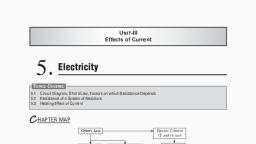
Unit-III, Effects of Current, , 5, , Electricity, , Topics Covered, 5.1, 5.2, 5.3, , Circuit Diagram, Ohm’s Law, Factors on which Resistance Depends, Resistance of a System of Resistors, Heating Effect of Current, , C hapter map, Electric Current, (I) and its unit, , Ohm’s Law, , Resistance, Factors, affecting, resistance, , Resistivity, Factors affecting, resistivity, , Advantage, Disadvantage, , Electric, Power, Safety Devices, , Combination of Resistances, In series, RS = R1 + R2 + R3, , Heating, Effect, , In parallel, , Electric, Fuse, , Earth, Wire, , 1= 1, 1, 1, + +, RP R1 R2 R3, Advantage, Disadvantage, , Topic 1. Circuit Diagram, Ohm’s Law, Factors on which Resistance Depends, , Circuit diagram: The schematic diagram in which different components of the circuit are represented by the, symbols conveniently used., Sl. No., Components, 1., Electric cell, 2., , A battery, , 3., , Plug key (switch open), , 4., , Plug key (switch closed), , 5., , A wire joint, , Symbols
Page 2 :
6., , Wire crossing without joining, , 7., , Electric bulb, , 8., , A resistor of resistance R, , 9., , Variable resistor or Rheostat, , 10., , Ammeter, , 11., , Voltmeter, , R, , Ohm’s law: It states ‘the potential difference across the given metallic wire in an electric circuit is directly, proportional to the electric current flowing through it, if the temperature remains constant’., V ∝I, V, V, = R ⇒ V = IR, = constant ⇒, I, I, , ‘R’ is a constant for a given metallic wire at a given temperature and is called resistance., Resistance: It is the property of a conductor to resist the flow of charges through it. Its S.I. unit is Ω (ohm)., Ohm: The resistance of a conductor is 1 ohm if 1 ampere current is passed across the two ends of conductor, having a potential difference of 1 V., 1 volt, V, 1 ohm =, R=, 1 ampere , I, •, , I=, , V, , The current through a resistor is inversely proportional to its resistance., R, , • If resistance is doubled, current gets halved if ‘V’ remains the same., Variable resistance (Rheostat): It is a device which is used to change the resistance in the circuit due to, which current flowing through the circuit will change., • Different components of an electric circuit, ammeter, voltmeter, torch bulb, Nichrome wire have different, resistance, therefore flow of current will be different in different components., • Motion of electrons in an electric circuit constitutes an electric current. The electrons are not completely, free to move within a conductor. They are held by attractive forces of the atoms in which they move., • Motion of electrons is retarted by resistance., • A good conductor offers low resistance., • A component of electricity that offers high resistance is a poor conductor., • An insulator offers maximum resistance and does not allow the current to flow., Factors on which resistance of a conductor depend:, (i) Length: Resistance of a wire is directly proportional to its length. If length of the wire is doubled,, resistance will also become double., (ii) Area of cross-section: Resistance is inversely proportional to the area of cross section of a conductor., A thin wire will have more resistance than a thick wire., (iii) Temperature: When we increase the temperature, resistance of metallic conductor will increase., (iv) Nature of material: A material may be a conductor with low resistance, semiconductor with medium, resistance, or an insulator having high resistance., R ∝l R∝, , l, l, 1, ⇒ ⇒ R = ρ., A, A, A, , , r(rho) is a constant of proportionality called resistivity of the material of conductor., Resistivity (r): Resistivity is defined as the resistance of a metallic wire whose area of cross section is 1 m2, and of length 1 m
Page 3 :
If A = 1 m2,, , , l = 1 m,, , then r = R, , ρ=R×, , A, l, , 2, ρ = ohm × m = ohm m, m, Its S.I. unit is Ω m (Ohm –metre)., Resistivity is a characteristic property of a material., Metals have low resistivity (10–8 to 10–6 Ω m), therefore they are good conductors., Insulators like rubber and glass have high resistivity, 1012 to 1017 Ω m., Resistance and resistivity of a material vary with temperature., Resistivity of an alloy is generally higher than the constituent metals. Alloys do not oxidise (burn) readily at, high temperature, therefore these are used in making heating devices like electric iron, toaster, immersion, rod, heaters, etc., Tungsten is used for filaments of electrical bulbs due to their high resistivity and high melting points., Copper and aluminium are used for electrical transmission lines due to their low resistance and high, conductance., , , •, •, •, •, •, •, •, •, , I. Multiple Choice Questions, , Exercise 5.1, , (1 Mark), , Choose the correct answer from the given options., 1. Electrical resistivity of a given metallic wire depends upon, (a) its length , (b) its thickness, (c) its shape , (d) nature of the material, 2. Identify the circuit (Fig) in which the electrical components have been properly connected., +, , –, , +, , –, , –, , V, , R, , A, , +, –, , +, , 4., 5., , 6., , +, –, , V, , (iii), , 3., , A, , +, , R, , –, , (iv), , (a) (i), (b) (ii), (c) (iii), (d) (iv), Electric current flows from ‘A’ to ‘B’ in metallic conductor. The point is at higher potential is, (a) A , (b) B, (c) Both have equal potential, (d) Both have lower potential, If electrons flow from A to B, current will flow from, (a) A to B, (b) B to A, (c) It will not flow (d) None of these, When a 4V battery is connected across an unknown resistor there is a current of 100 mA in the circuit., The value of the resistance of the resister is:, (a) 4 Ω, (b) 40 Ω, (c) 400 Ω, (d) 0.4 Ω�, [CBSE Sample Paper 2019-2020], A cell, a resistor, a key and ammeter are arranged as shown in the circuit given below. The current, recorded in the ammeter will be, K – +, R, R, –, + –, + –, A+, K, –, K, R, A, –, +, A+, (i), (ii), (iii), (a) maximum in (i) , (c) maximum in (iii) , , (b) maximum in (ii), (d) the same in all the cases, , II. Assertion-Reason Type Questions, (1 Mark), , For question numbers 1 and 2 two statements are given-one labeled as Assertion (a) and the other labeled, Reason (R). Select the correct answer to these questions from the codes (a), (b), (c) and (d) as given below:, (a) Both ‘A’ and ‘R’ are true and ‘R’ is correct explanation of the Assertion., (b) Both ‘A’ and ‘R’ are true but ‘R’ is not correct explanation of the Assertion.
Page 4 :
(c) ‘A’ is true but ‘R’ is false., (d) ‘A’ is false but ‘R’ is true., 1. Assertion: Resistance depends on length and area of cross-section of material and temperature., , Reason: Resistivity is a characteristic property of material., 2. Assertion: Fuse wire is thin and has high resistance., , Reason: Alloys do not oxidise readily at high temperature., , III. Very Short Answer Type Questions, , (1 Mark), , 1. Let the resistance of an electrical component remain constant, while the potential difference across the, two ends of the component decreases to half of its former value. What change will occur in the current, through it?�, [NCERT] [HOTS], 2. Which among iron and mercury is a better conductor?, , (Given: rFe = 10.0 × 10⁻⁸ W – m, rHg = 95 × 10–8 W – m, 3. Write the S.I. unit of resistivity.�, [Delhi 2015, 16], 4. Mention two reasons why tungsten is used for making filaments of electric lamps., [Delhi 2016], 5. How does resistivity of alloys compared with those of pure metals from which they have been, formed? , [CBSE 2014], 6. State the difference between a wire used in the element of electric heater and in fuse wire., [Delhi 2013] [CBSE 2014], 7. Name a device which helps to maintain the potential difference across a conductor., [CBSE 2014], 8. Draw a circuit diagram having the following components:, (a) Bulb (b) A two cell battery (c) Ammeter (d) A closed key, 9. Name the factors on which the resistance of a conductor depend?, [NCERT], OR, List the factors on which the resistance of a conductor in terms of shape of a wire depends., 10. What happens to the resistance of a conductor when its temperature is increased?, [CBSE 2010], 11. Nichrome is used to make the element of an electric heater, why?, [CBSE 2010], 12. Mention two special features of the material to be used as an element of an electric iron.�[CBSE 2014], 13. What happens to resistance of a conductor when its area of cross section is increased?, [Delhi 2011], 14. What does electric circuit mean?�, [NCERT], 15. List two factors on which resistance depends.�, [CBSE 2015], 16. In an electric circuit, state the relationship between the direction of conventional current and the, direction of flow of electrons.�, [CBSE 2014], 17. A given length of wire is doubled on itself and the process is repeated once again. By what factor does, the resistance of wire will change? , [CBSE 2011], , IV. Short Answer Type Question-I�, , (2 Marks), , 1. Out of the two wires ‘X’ and ‘Y’ of the same material as shown below, which one has greater resistance?, Justify your answer.�, [Delhi 2012], , V. Short Answer Type Questions-II�, , (3 Marks), , 1. Resistance of a metal wire of length 1 m is 26 Ω at 20°C. If the diameter of the wire is 0.3 mm, what will, be the resistivity of the metal at that temperature?, [NCERT] [HOTS], 2. The figure below shows three cylindrical copper conductors along their face areas and lengths. Discuss, in which geometrical shape the resistance will be the highest., [Delhi 2013]
Page 5 :
3. Calculate the resistance of 1 km long wire of copper of radius 1 mm. (Resistivity of copper is, 1.72 × 10⁻⁸ Ω m.)�[Delhi 2013], 4. The resistance of a wire of 0.01 cm radius is 10 Ω. If resistivity of the material of wire is 50 × 10–8 ohm, metre, find the length of the wire. , [Delhi 2016], 5. The resistance of a wire of length 250 m is 1 ohm. If the resistivity of the material of wire is, 1.6 × 10⁻⁸ ohm metre, find the area of cross-section of the wire. How much does the resistance change, if the diameter of the wire is doubled?�, [Delhi 2016], 6. The electrical resistivity of three materials A, B, C are given below:, ‘A’ = 2.3 × 10³ ohm metre ‘B’ = 2.63 × 10⁻⁸ ohm metre ‘C’ = 1.0 × 10¹⁵ ohm metre, Which material will you use for making (i) electric wires, (ii) handles for soldering iron and (iii) solar, cells? Give reason to support your answer., 7. Suppose the ammeter or voltmeter you are using in Ohm’s law experiment do not have +ve and –ve, terminal markings, how will you use such an ammeter or voltmeter in the circuit?�, [Delhi 2015], 8. Study the V–I graph for a resistor as shown in the figure and prepare, a table showing the values of I (in amperes) corresponding to four, different values of V (in volts). Find the value of current for V = 10, volts. How can we determine the resistance of the resistor from this, graph?, 9. Name and define SI unit of resistance. Calculate the resistance of a, resistor if current flowing through it is 200 mA, when the applied, [CBSE 2014], potential difference is 0.8 V., 10. V–I graph for two wires A and B are shown in the figure. If both the wires are of same, length and same thickness, which of the two is made of a material of high resistivity?, Give justification for your answer., 11. The figure below shows three cylindrical copper conductors along with their face, areas and lengths. Compare the resistance and the resistivity of the three conductors. Justify your, answer.�, , , 12. The potential difference between the terminals of an electric heater is 60 V when it draws a current of, 4 A from the source. What current will the heater draw if the potential difference is increased upto 120, V?�[NCERT], 13. (i) �How much current will an electric bulb draw from a 220 V source, if resistance of the filament of a, bulb is 1200 Ω?, , (ii) How much current will an electric heater coil draw from a 220 V source, if the resistance of the, heater coil is 100 Ω? �, [NCERT] [Delhi 2012], 14. A wire of given material having length l and area of cross-section A has a resistance of 4 Ω. What would, be the resistance of another wire of the same material having length l/2 and area of cross-section 2A?, �[NCERT] [HOTS], 15. A copper wire has diameter 0.5 mm and resistivity of 1.6 × 10⁻⁸ Ω m. What will be the length of this, wire to make its resistance 10 Ω? How much does the resistance change if the diameter of the wire is, doubled?�[NCERT]
Page 6 :
16. The values of current I flowing in a given resistor for the corresponding values of potential difference, V across the resistor are given below :, I (amperes), , 0.5, , 1.0, , 2.0, , 3.0, , 4.0, , V (volts), , 1.6, , 3.4, , 6.7, , 10.2, , 13.2, , Plot a graph between V and I and calculate the resistance of that resistor. �[NCERT] [HOTS], 17. When a 12 V battery is connected across an unknown resistor, there is a current of 2.5 mA in the, circuit. Find the value of the resistance of the resistor.�, [NCERT], 18. A piece of wire of resistance 20 Ω is drawn out of a material so that its length, B, is increased to twice of its original length. Calculate the resistance in the, new situation.�, [HOTS], A, 19. V-I graph for two wires ‘A’ and ‘B’ are shown in the figure. If both the wires, are of same length and are of same thickness, which of these two is made of, the material of higher resistivity? Give justification for your answer., 20. (i) What are the values of mA and mA in amperes?, , (ii) Draw the symbols of battery and rheostat?�, [CBSE 2014], , VI. Long Answer Type Questions�, , (5 Marks), , 1. (i) Write an expression for the resistivity of a substance., , (ii) State the SI unit of resistivity., , (iii) Distinguish between resistance and resistivity., , (iv) Name two factors on which the resistivity of a substance depends and two factors on which it does, not depend. �, [Delhi 2015], 2. List two distinguishing features between the resistance and resistivity of a conductor. A wire is, stretched so that its length becomes 6/5 times of its original length. If its original resistance is 25 W,, find its new resistance and resistivity. Give justification for your answer in each case.� [Delhi 2016], 3. State Ohm’s law. Draw a labelled circuit diagram to verify this law in the laboratory. If you draw a, graph between the potential difference and current flowing through a metallic conductor, what kind of, curve will you get? Explain how would you use this graph to determine the resistance of the conductor., �[Delhi 2016], 4. You have been assigned a duty to create awareness in your school, about saving electricity., , (i) Write any two ways by which you will create awareness, among your schoolmates about saving electricity., , (ii) Explain how saving electricity is important at individual level, as well as at national level. [Delhi 2015], 5. (i) Draw a closed circuit diagram consisting of a 0.5 m long, nichrome wire XY, and ammeter, a voltmeter, four cells of 1.5, V each and a plug key., , (ii) Following graph was plotted between V and I values:, What would be the values of V/I ratios when the potential, difference is 0.8 V, 1.2 V and 1.6 V respectively? What, conclusion do you draw from these values?, , Answers 5.1, I. 1. (d) It depends only upon nature of the material. Resistance depends on the length of wire and area of, cross section., , 2. (b) It is correct because Ammeter should be connected in series and voltmeter should be connected in, parallel., , 3. (a) ‘A’ because current flow from higher to lower potential., , 4. (b) Current flows in opposite direction to the direction of flow of electrons, B to A., , 5. (b) V = IR, V = 4V, I = 100 mA = 0.1 A; Hence, R = V/I = 4/0.1 = 40., , 6. (d) It will be same in all cases, II. 1. (b) Both ‘A’ and ‘R’ are true but ‘R’ is not correct explanation of the assertion., , 2. (b) Both ‘A’ and ‘R’ are true but ‘R’ is not correct explanation of the assertion.
Page 7 :
The current flowing through the electrical component will get halved., Iron, Ω m (ohm metre), (i) High resistivity, (ii) High melting point, Alloys have higher resistivity as compared to pure metals., The wire used in the elements of an electric heater has high melting point whereas a fuse wire has low, melting point., 7. Cell or battery eliminator., 8., , III. 1., 2., 3., 4., 5., 6., , 9. (i) Nature of material, (ii) Length of conductor [or R µ l], , (iii) Area of cross section of the conductor [or R µ 1/A], (iv) Temperature, 10. Its resistance increases., 11. It is an alloy with high resistivity and high melting point., 12. The material should have (i) high resistivity, (ii) high melting point., l, 13. Resistance decreases, ... R ∝, , Resistance is directly proportional to length but inversely proportional, A, to area of cross-section., 14. It is a continuous and closed path in which current flows with the help of conducting wires. It consists, of a cell, an ammeter, voltmeter, plug key, bulb, etc., 15. (i) Length, (ii) Area of cross section, It is directly proportional to the length and inversely proportional to the area of cross section of a, resistor., 16. The direction of conventional current is opposite to the direction of flow of electrons., 1, 17. Length becomes 4 times whereas area becomes, times of the original value. Since,, 4, L, 4L, 16 L, L, R=ρ =ρ, =ρ, = 16 ρ, where r (rho) is resistivity, L is length and ‘A’ is area of cross section., , A, A, A, A, 4, , \ Resistance will become 16 times of the original value., IV. 1. ‘Y’ has more resistance because resistance is directly proportional to the length of the wire., V. 1. R = 26 Ω, l = 1 m, d = 0.3 mm = 3 × 10⁻⁴ m, d 3 × 10 −4, r= =, = 1.5 × 10 −4 m, 2, 2, 22, A = pr2 ⇒ A =, × (1.5 × 10⁻⁴)2, 7, R × A 26 × 22 × 2.25 × 10 −8, = 1.84 × 10⁻⁶ W m, , ρ=, =, l, 7 × 1m, L, A, 2L, L, R2 = ρ ×, = 4ρ × = 4 R 1, A/2, A, L/2 1, L 1, R3 = ρ ×, = × ρ × = R1, 2A 4, A 4, , 2. R1 = ρ ×, , (i), (ii), (iii), , Thus in figure (b) the resistance is maximum., So, from equations (i), (ii) and (iii), we get R2 > R1 > R3.
Page 8 :
Hence, the cylinder having length (2L) and area of cross-section (A/2) has the highest resistance, followed by the cylinder having length (L) and area of cross section (a), while cylinder with length, (L/2) and area of cross-section (2A) has the least resistance. This is because resistance of a substance, is directly proportional to the length and is inversely proportional to the area of cross-section., 3. R = ρ ×, , l, A, , 22, × 1 × 10⁻⁶, , r = 1.72 × 10⁻⁸ Ω m; r = 1 mm = 1 × 10⁻³ m; A = pr2 =, 7, l = 1 km = 1000 m, ⇒ R=, , 4. R = r ×, , 1.72 × 10 −8 × 1000 × 7 12.04, 120.4, =, × 10 −8 + 3 + 6 =, = 5.473 Ω, 22 × 1 × 10 −6, 22, 22, l, A, , R = 10 W,, r = 50 × 10–8 W m, , \ l=, 5. R = r, , r = 0.01 × 10⁻² m = 1 × 10⁻⁴ m, A = pr2 =, , 22, × 1 × 10⁻⁸, 7, , R × A 10 × 22 × 10 −8 220, = 0.628 m = 62.8 cm, =, =, ρ, 50 × 10 −8 × 7, 350, , ρl, l, ⇒ A=, R, A, , 1.6 × 10 −8 Ω m × 250 m, = 4 × 10⁻⁶ m2, 1Ω, If diameter is doubled then area of cross-section becomes four times and the resistance will become one, fourth, i.e., 0.25 W., 6. (i) �‘B’ will be used for electric wires because it has lowest resistivity, therefore current can flow easily., , (ii) ‘C’ will be an insulator, so it can be used for handles of soldering iron. Since its resistivity is very, high, therefore current cannot pass through it., , (iii) ‘A’ will be used in solar cells because it is a semiconductor which can convert solar energy into, electric energy., 7. (i) Connect the device in the circuit with battery., , (ii) Close the circuit and notice the deflection of the pointer., , (iii) If the deflection is in the opposite direction i.e. below zero, then interchange the terminals., , A =, , 8., , I (in amp), , 2, , 4, , 6, , 8, , V (in Volt), , 1, , 2, , 3, , 4, , When V = 10 Volts, I = 5 amperes, then, , R=, , V 10 V, =, =2Ω, I, 5A, , 9. (i) The SI unit of resistance is Ohm (W)., , (ii) If the current of 1 ampere flows through a wire on applying a potential difference of one volt across, it, then the resistance of the wire is said to be 1 W., , (iii) I = 200 mA = 200 × 10–3 A, V, 0 .8, =, = 4 ohms, 0 .2, I, 10. Greater the slope of V–I graph, greater will be the resistance of the given metallic wire. In the given, graph, wire A has greater slope than B. Hence, wire A has greater resistance., For the wires of same length and same thickness, resistance depends on the nature of the material of, wire, i.e., R1, ρ, l, l, , R1 = ρ1 and R 2 = ρ2, ⇒, = 1 or R ∝ ρ, A, A, R2, ρ2, , R =, , Since, R1 > R2. Hence, wire ‘A’ is made of a material of high resistivity.
Page 9 :
11. For the geometrical shapes shown in figure:, , l, ρL, L / 3 1 ρL 1, 3L , Ra = ρ A ; Rb = ρ A / 3 = 9 A = 9R a ; Rc = ρ 3 A = 9 A = 9 R a, , , Hence Rb > Ra > Rc, ρ = ρb = ρc because all the three conductors are of same material., a, , , 12. V = 60 V, I = 4 A, V 60, =, = 15Ω [ By Ohm’s Law: V = IR], R=, , I, 4, Now, V = 120 V, I = ? R = 15 Ω, V 120, I=, =, =8A, R, 15, , 13. (i) V = 220 V, R = 1200 Ω, V, 220, I=, =, = 0.18 A [ By Ohm’s Law: V = IR], , R 1200, , (ii) Now, V = 220 V, R = 100 Ω, 220, I=, = 2 .2 A, , , 100, 14. R1 = ρ ×, , l, = 4 Ω�, A, , Also, R 2 = ρ ×, , l/2, 1 l, = ρ× ×, 2A, 4 A, , 1, 1, , R 2 = R1 = × 4 = 1 Ω, 4, 4, 15. ρ = 1.6 × 10 −8Ω m ; R = 10 Ω, d = 0.5 mm = 5 × 10⁻⁴ m [ 1 mm = 10–3 m], 22, 5, × 10–4 m = 2.5 × 10⁻⁴ m; A = pr2 =, × (2.5 × 10⁻⁴)2 m2, 7, 2, A, , ρ=R×, l, 22 6.25 × 10 −8, 10 × 22 × 6.25 × 10 −8 1375, ×, 1.6 × 10–8 = 10 ×, ⇒ l=, =, = 122.77 m, 7, l, 7 × 1.6 × 10 −8, 11.2, r =, , 16. The slope of the graph is equal to the resistance., Change in V ∆V 13.2 − 1.6 ,, , =, =, R=, Change in I, ∆I, 4 .0 − 0 .5, 11.6, , R=, = 3.314 Ω, 3 .5, 17. V = 12 V, I = 2.5 mA = 2.5 × 10⁻³ A, , (1 mA = 10–3 A), 12, 12000, V, R=, =, =, = 4800 Ω = 4.8 k Ω, , I 2.5 × 10 −3, 2 .5, , ( By Ohm’s Law: V = IR), l, 2l, 18. R1 = r ×, ; R2 = r ×, A, A, 2l, ρ×, R2, A, , \, =, l, R1, ρ×, A, , ⇒ R2 = 2R1 = 2 × 20 = 40 W, , A, , ∵ R = ρ × l , ,
Page 10 :
19. ‘A’ has greater resistivity than ‘B’. It depends upon the nature of material. High resistivity means, lower value of electric current flowing through the wire., 20. (i) 1mA = 10–3A, 1mA = 10–6A., , (ii), , is the symbol of battery, and, , or, , is the symbol of rheostat., , RA, , (ii) Its SI unit is W m., l, (iii) Resistivity is a characteristic property of a material that does not depend upon the dimensions, of the material whereas resistance depends upon the dimensions of the material., VI. 1. (i) Resistivity (r) =, , , (iv) Resistivity does not depend on the:, , (a) length of conductor,, Resistivity depends on the:, , (a) nature of material of conductor, 2., , (b) area of cross section of conductor, (b) temperature of conductor, , Resistance, , Resistivity, , (i) �It is the ratio of voltage over current at a, particular temperature., , (i) �It is the resistance of a wire of length 1 m and, area of cross section 1 m2., , (ii) �Its S.I. unit is ohm., , (ii) �Its S.I. unit is ohm metre., , (iii) It is the property of a conductor., , (iii) It is the property of the material of the conductor., , �, (Any two), Since resistance is directly proportional to the length and is inversely proportional to the area of cross, section., 25, 150, 216, 6, \ New Resistance: R = ×, × 36 =, = 43.20 ohms, 2 =, 5 5, 5 × 25, 5, 6 , When the wire is stretched, its length becomes 6/5 times of its original length, and area of cross-section, will become 5/6. Resistivity will remain the same because it does not depend upon the length and area, of cross section. It depends on the nature of material of the substance and the temperature., 3. Ohm’s Law: It states that ratio of potential difference and current is constant and is equal to the, resistance of the conductor at a particular temperature. In other words, the current flowing through a, conductor is directly proportional to the potential difference at a constant temperature., The graph between V and I will be a straight line., Slope = tan θ = ‘R’, BC, Slope =, =R, AC, 4. (i) �Speaking over it in the morning assembly in school., , • Putting posters over it on the school notice board., , (ii) If we save electricity, it can be used by those villages which do not have electricity., , • It can be used in industries, agriculture and for other useful purposes., , • It improves the national economy because high speed trains, industries, development in villages, depends upon electricity., 5. (i)
Page 11 :
(ii) The V/I ratio for, 0.8, V, V, 1 .2, = 2.67 ; • V = 1.2 V,, is, =, • V = 0.8 V,, = 2.67, 0.3, I, I, 0.45, V 1 .6, • V = 1.6 V,, =, = 2.67, I, 0 .6, It shows that V a I or, , V, = constant., I, , Topic 2. Resistance of a System of Resistors, There are two methods of joining the resistors together., , Resistors in Series, When resistors are joined end to end, it is called that resistors are connected in series., (i) The value of current in the ammeter remains the same, independent of its position in the electric circuit., It means that in a series combination of resistors, the current remains the same in every part of the circuit, or same current flows through every resistor., , (ii) In the above circuit in V is equal to the sum of V1, V2, V3, that is total potential differences (V) across a, combination of resistors in series is equal to sum of potential difference across the individual combinations,, i.e., , V = V 1 + V2 + V 3, (iii) The current through each resistor and all the three resistors is I., V = IR, , \ , V1 = IR1, V2 = IR2 and V3 = IR3, So,, V = V1 + V2 + V3 ⇒ IR = IR1 + IR2 + IR3, or R = R1 + R2 + R3, Thus we can conclude that when several resistors are joined in series combination, then equivalent, resistance of the combination is equal to the sum of their individual resistances and is thus greater than, any of the individual resistance., RS = R1 + R2 + R3, , Resistors in Parallel, (i) Suppose we connect three resistances R1, R2, R3 in parallel combination as shown in the diagram., (ii) Let us connect it with the battery, a plug key, an ammeter as shown in the diagram., (iii) Also connect voltmeter in parallel combination with the resistors as shown.
Page 12 :
By applying a potential difference V, the current flowing in the, circuit be I. This circuit is distributed in different branches., Suppose I1, I2, I3 be the current in each resistor., Then we observe, I = I1 + I2 + I3, According to Ohm’s Law, , , ∵, , , I=, , V, Rp, , I1 =, , V, ;, R1, , I2 =, , V, ;, R2, , I3 =, , V, R3, , V, V, V, V, =, +, +, R p R1 R 2 R 3, , I = I1 + I2 + I3 ⇒, , 1, 1, 1, 1, =, +, +, R, R, R, R, 1, 2, 3, p, , Circuit in series vs Circuit in parallel (Disadvantages of series circuit), , (i) �We have observed in series circuit, the current is constant throughout the electric circuit. Thus, it is not, practical to connect an electric bulb and electrical heater in series, because they need current of widely, different values to operate properly. Total resistance increases in a series connection., , (ii) �Another disadvantage of series circuit is that when one component fails, the entire circuit is broken and, current stops flowing in the circuit. You must have seen in ‘fairy lights’ used in diwali, if one bulb fuses,, the circuit is broken, none of the small bulbs work or light up., , Parallel Circuit Advantages, , (i) �It divides the current through the electric gadgets., , (ii) �The total resistance in a parallel circuit decreases. It is helpful when gadgets have different resistances, and they require different current to operate., , Exercise 5.2, I. Multiple Choice Questions, , (1 Mark), , Choose the correct answer from the given options., 1. When the current passing through each resistor is same, the circuit is called, (a) series circuit, (b) parallel circuit, (b) Both (a) and (b) (c) None of these, 2. In parallel circuit, which of the following is same across resistors, (a) Current , (b) Potential difference, (c) Resistance , (d) Resistivity, 3. When resistance is doubled at constant voltage, current will become., 1, 1, (b) 2 times, (c), (d) 4 times, (a), 2, 4, 4. Resistance in a circuit if current flowing is doubled will become, (a) double, (b) half, (c) four times, (d) remains same, 5. A piece of wire of resistance R is cut into five equal parts. These parts are then connected in parallel., If the equivalent resistance of this combination is R′, then the ratio R/R′ is, (a) 1/25, (b) 1/5, (c) 5, (d) 25, [CBSE 2020, NCERT], 6. Two conducting wires of the same material and of equal lengths and equal diameter are first connected, in series and then in parallel in a circuit across the same potential difference. The ratio of heat produced, in series and parallel combinations would be, (a) 1:2, (b) 2:1, (c) 1:4, (d) 4:1�, [NCERT], , II. Assertion-Reason Type Questions, (1 Mark), For question numbers 1 and 2 two statements are given-one labeled as Assertion (a) and the other labeled, Reason (R). Select the correct answer to these questions from the codes (a), (b), (c) and (d) as given ahead:, (a) Both ‘A’ and ‘R’ are true and ‘R’ is correct explanation of the Assertion., (b) Both ‘A’ and ‘R’ are true but ‘R’ is not correct explanation of the Assertion.
Page 13 :
(c) ‘A’ is true but ‘R’ is false., (d) ‘A’ is false but ‘R’ is true., 1. Assertion: In parallel circuit, the current is divided into electrical gadgets, therefore, used in domestic, circuit., , Reason: The resistance in parallel circuit decreases, therefore, useful., 2. Assertion: Fairy lights circuit is connected in series connection., , Reason: In series combination, if one component fails then complete circuit is broken., , III. Very Short Answer Type Questions�, , (1 Mark), , 1. Draw a schematic diagram of a circuit consisting of a battery of three cells of 6 V each, a, 5 W resistor, an 8 W resistor and a 12 W resistor and a plug key, all connected in series., [NCERT], 2. Judge the equivalent resistance when the following are connected in parallel:, (i) 1 W and 106 W, (ii) 1W, 103 W and 106 W�[NCERT], 3. What are the advantages of connecting electrical devices in parallel with the battery instead of, connecting them in series?�, [NCERT], 4. Two unequal resistances are connected in parallel. If you are not provided with any other parameters, (eg. numerical values of I and R), what can be said about the voltage drop across the two resistors?, �[CBSE Sample Paper 2020-21], , IV. Short Answer Type Questions-I�, , (2 Marks), , 1. If you connect three resistors having values 2 W, 3 W and 5 W in parallel, calculate the equivalent, resistance., 2. B1, B2, B3 are three identical bulbs connected as shown in the figure., When all the three bulbs glow, a current of 3 A is recorded by the, ammeter A., , (i) What happens to the glow of the other two bulbs when bulb B1 gets, fused?, , (ii) What happens to the reading of A1, A2, A3 and A when bulb B2 gets, fused. [CBSE 2010], 3. Redraw the circuit in the above question, putting an ammeter to, measure the current through the resistors and a voltmeter to measure, I, →, the voltage across the 12 W resistor. What would be reading in the, A, ammeter and the voltmeter?�, [NCERT] [HOTS], 4. A student has two resistors- 2 W and 3 W. She has to put one of them, R1 = 4W, 12V, R2, in place of R2 as shown in the circuit. The current that she needs in, the entire circuit is exactly 9A. Show by calculation which of the two, B, resistors she should choose., , V. Short Answer Type Questions-II�, , (3 Marks), , 1. What is (a) the highest, (b) the lowest total resistance that can be secured by combination of four coils, of resistances 4 W, 8 W, 12 W, 24 W?�, [NCERT], 2. Show how you would connect three resistors, each of resistance 6 W, so that the combination has a, resistance of (i) 9 W, (ii) 4 W.�, [HOTS], 3. (i) What are the disadvantages of resistances connected in a series circuit?, , (ii) Find the resistance between A and B in the following network., [Delhi 2014]
Page 14 :
4. What are the advantages of connecting electrical devices in parallel combination with the battery, rather than in series combination?, 5. Find the current drawn from the battery by the network of four resistors as shown in the figure., , 6. Show how would you join three resistors, each of resistance 9 Ω so that the equivalent resistance of the, combination is (i) 13.5 Ω, (ii) 6 Ω?�[CBSE 2018], 7. If three resistors of 6 Ω, 9 Ω and 21 Ω are connected in series to a 12 V battery, find:, , (a) The total resistance of the circuit., , (b) The current flowing through the circuit., , (c) The potential difference across the 21 Ω resistor., 8. An electric lamp of 100 W, a toaster of resistance 50 W, and a water filter of resistance 500 W are, connected in parallel to a 220 V source. What is the resistance of an electric iron connected to the same, source that takes as much current as all the three appliances, and what is the current flowing through, it?�[NCERT], 9. Study the following electric circuit and find the, , (i) current flowing through the circuit and, , (ii) the potential difference across 10 W resistor.�, , [Delhi 2016], , 10. Figure shows a 2 W resistor and a 6 W resistor connected in series, 2, with a 4 V battery. Calculate:, , (a) the combined resistance of the resistors., , (b) the current in the battery., , (c) the current in 2 W resistor., 11. How can three resistors of resistances 2 W, 3 W, and 6 W be, connected to give a total resistance of (a) 4 W, (b) 1 W?�[NCERT], 12. The parallel combination of two 10 W resistors are placed across, 4V, the terminals of a 24 V battery., , (a) What is the effective resistance of the parallel combination of resistances in the circuit?, , (b) What is the current through the entire circuit?, , (c) What is the current through each branch of the circuit?, 13. How many 176 W resistors (in parallel) are required to carry 5 A current on a 220 V line?, 14. A hot plate of an electric oven connected to a 220 V line has two coils A and B, each of 24 W, resistance, which may be used separately, in series, or in parallel. What are the values of current in, the these cases?�, [NCERT]
Page 15 :
VI. Long Answer Type Questions�, , (5 Marks), , 1. (i) �, What is meant by series combination and parallel combination of, resistances?, , (ii) In the circuit diagram given below five resistances of 5W, 20W, 15W, 20W, and 10 W are connected as given in the figure to a 6 V battery., Calculate: (a) Total resistance in the circuit., , (b) Total current flowing in the circuit. [Delhi 2016], 2. Study the following electric circuit and find (i) the current flowing in the, circuit and (ii) the potential difference across the 10 W resistor., , 20 Ω, 15 Ω, 20 Ω, 5Ω, 6V, , , 3. Find the net current flowing through the following electric circuit:, , , 4. (a) �, With the help of suitable circuit diagram prove that the, reciprocal of the equivalent resistance of a group of resistances, joined in parallel is equal to the sum of the reciprocal of the, individual resistances., , (b) �In an electric circuit two resistors of 12 W each are joined in, parallel to a 6V battery. Find the current drawn from the, battery., 5. Figure shows a 3 W resistor and a 6 W resistor connected in parallel, across a 1.5 V cell., Calculate the current across: (i) 3 W resistor, (ii) 6 W resistor, (iii), the cell, (iv) calculate the resistance of the parallel combination of, 3 W and 6 W resistors., , Answers 5.2, I. 1. (a) The circuit is called series circuit., , 2. (b) Potential difference is same., V, 1, I =, R, 2, 4. (d) Resistance does not depend upon current., , 3. (a) It will became, , 5. (d), , , , 1, R, , ′, , =, , R′ =, , 1, 1, 1, 1, 1 25, +, +, +, +, =, R R R R R, R, 5, 5, 5, 5, 5, R, Ω, 25, , ⇒, , R, = 25 . So option (d) is correct., R′, , 1.5 V, , 10 Ω
Page 16 :
6. (c) �Resistances of identical conducting wires are equal. Let R be the resistance of each resistor in series, combination., \ Rs = R + R = 2R, V2, 2R, 1, 1 1, 2, When resistances are connected in parallel,, =, +, =, RP R R R, V2, H, =, P R / 2, , Hs = Heat produced in series. Hence Hs =, , RP =, , R, , 2, , HS V 2, 1, R, =, ×, = . So option (c) is correct., HP 2R 2V 2 4, II. 1. (a) Both ‘A’ and ‘R’ are true and ‘R’ is correct explanation of the assertion., , , , 2. (b) Both ‘A’ and ‘R’ are true but ‘R’ is not correct explanation of the assertion., III. 1., , 2. Equivalent resistance in parallel combination of resistances is always less than the lowest individual, resistance i.e. less than 1 Ω in both the cases (i) and (ii)., 3. Parallel circuit advantages:, , (a) Voltage is same across all the components when connected in parallel., , (b) Parallel combination of resistances helps us to obtain an overall lower potential than the resistances, used., , (c) In household circuit, parallel connection is useful because each appliance has its own ON/OFF, switch., , (d) A fault in one appliance will not affect the working of other appliances.�, (Any two), 4. Voltage-drop is same across both resistors., 1, 1, 1, 1, 1 1 1, 15 + 10 + 6 31, +, +, = + + =, =, IV. 1., =, R, R1 R 2 R 3 2 3 5, 30, 30, 30, = 0.967 Ω, 31, 2. (i) The glow of bulbs B2 and B3 will remain same because they are in parallel connection with bulb B1., , (ii) A 1 shows 1 ampere reading, A 2 shows zero and A 3 show 1 ampere reading. ‘A’ will show, 2 A reading., 3. RS = R1 + R2 + R3 = 5 + 8 + 12 = 25 Ω; V = 6 V, , , , R=, , V, 6V, =, = 0.24 A, , I=, R 25 Ω, In series combination current in all resistances is same., Here, I = 0.24 A across 12 Ω resistance, , \ Voltmeter reading, V = IR = 0.24 × 12 = 2.88 V, , \, I = 0.24 A,, V = 2.88 V, 4. The overall current needed = 9A. The voltage is 12V, Hence by Ohm’s law V=IR,, 4, 12, =, Ω. = R, The resistance for the entire circuit =, 3, 9, R1 and R2 are in parallel., (R1R 2 ) = 4R 2 = 4 �, Hence, R =, (R1+R 2 ) (4 + R 2 ) 3, R2 = 2Ω
Page 17 :
V. 1. (a) The highest resistance can be obtained by connecting all resistances in series, i.e., Rs = R1 + R2 + R3 + R4 = 4 Ω + 8 Ω + 12 Ω + 24 Ω = 48 Ω, (b) The lowest resistance can be obtained by parallel combination:, 1, 1, 1, 1, 1, 1, 1, 6 + 3 + 2 + 1 12, 1 1, =, =, +, +, +, = + +, +, =, R p R1 R 2 R 3 R 4 4 8 12 24, 24, 24, , Rp = 2 Ω, (i) When two 6 Ω resistances are connected in parallel and connected to another 6 Ω in series, we get, 9 Ω resistance., 1, 1 1 2 1, = + = = ⇒ R p = 3 Ω ⇒ RNet = R3 + RP = 6 + 3 = 9 Ω, Rp 6 6 6 3, , (ii) When two resistors are connected in series and third one is in parallel, we get 4 Ω resistance., Rs = R1+ R2 = 6 + 6 = 12 Ω, 2., , 1, 1, 1, 1, 1 1+2, 3, , =, +, =, + =, =, R p R s R 3 12 6, 12, 12, , fi Rp = 4 Ω, , 3. (i) Circuit in series vs Circuit in Parallel (Disadvantages of series circuit):, , (a) If one electrical appliance stops working due to some factor, then all the other appliances also stop, working., , (b) All the electrical appliances have only one switch due to which they can’t turned on or off individually., , (c) The appliances do not get the same voltage as of the input power supply., , (d) Overall resistance increases due to which the current from the input power supply becomes low., , (ii) Two resistances of 2 Ω are in series \ Rs = R1 + R2 = 2 + 2 = 4 Ω, , The third resistance of 4 Ω is parallel to Rs \, , 1, 1, 1, 1 1 2, =, +, = + =, Rp Rs R3 4 4 4, , , ⇒ RP = 2 Ω, 4. (1) �The current required by each device is different which is possible only in parallel combination., , (2) If one device fails others can still work., , (3) Total resistance in the circuit is decreased., 5. R1, R2, R3 are in series combination and R4 is in parallel combination to these combination of resistors., Equivalent resistance of the given network is given as:, 1, 1, 1, 1, 1, 1, 1, 3+1, 4, +, +, =, +, =, =, =, =, R, R 4 R1 + R 2 + R 3, 10 10 + 10 + 10 10 30, 30, 30, , , , 30, = 7 .5 Ω, 4, 30 2, V, 3, =, =, =, Current drawn from the battery I =, R 7.5 75 5, , \R=, , 6., , (i) �, , ⇒ I = 0.4 A, , �, , Two 9 ohm resistors in parallel combination are connected to one 9 ohm resistor in series;, 1, 1 1 2, 9, , = + = \ R p = Ω, Rp 9 9 9, 2, R = 9 Ω +, , 9, Ω = 13.5 Ω, 2, , , (ii) Two 9 ohm resistors in series connected are connected to one 9 ohm resistor, in parallel;
Page 18 :
Rs = 9 Ω + 9 Ω = 18 Ω, , , 1, 1 1, 3, =, + =, R 18 9 18, (b) I =, , 7. (a) 36 W, , \ , , R=6Ω, , V 12 V, =, = 0.33 A, R 36 Ω, , (c) V = R × I ⇒ V = 21 × 0.33 = 6.93 V, , 8. R1 = 100 Ω, R2 = 50 Ω, R3 = 500 Ω, V = 220 V, , , 1, 1, 1, 1, 1, 1, 1, 5 + 10 + 1, 16, =, =, +, +, +, +, =, =, R p R1 R 2 R 3, 100 50 500, 500, 500, , RP =, , 500 125, =, Ω = 31.25 Ω, 16, 4, , V 220 × 4 880, =, =, = 7.04 A, R, 125, 125, Current will remain the same if the electric iron is connected with the same source, i.e., , I = 7.04 A, 125, = 31.25 Ω across the electric iron., R =, 4, 9. (i) Rs = R1 + R2 = 10 Ω + 20 Ω = 30 Ω, , Current through all appliances =, , I =, , V, 3V, =, = 0 .1 A, R 30 Ω, , , (ii) V = I × R = 0.1 × 10 = 1 V, 10. (a) Rs = R1 + R2 = 2 W + 6 W = 8 W, V 4, = = 0 .5 A, R 8, (c) Current across the 2 W resistor = 0.5 A, 11. (a) In order to get 4 W resistance, 2 W resistance should be, connected in series with a combination of 3 W and 6 W, resistances connected in parallel with each other., , , (b) I =, , 1, 1, 1, 1 1 3, =, +, = + = ⇒ Rp = 2 Ω, , R p R1 R 2 3 6 6, , Rs = R3 + Rp = 2 W + 2 W = 4 W, , (b) In order to get 1 W resistance all the three resistors should be, connected in parallel., 1, 1, 1, 1, =, +, +, R p R1 R 2 R 3, =, , 1 1 1 3+2+1 6, + + =, = =1, 2 3 6, 6, 6, , , Rp = 1 W, 12. (a), , 1, 1, 1, 1, 1, 2 1, +, =, +, =, =, ⇒ RP = 5 Ω, =, RP, R1 R 2 10 10 10 5, , , (b) From Ohm’s law, I =, , (c) I1 =, , V 24, =, = 2 .4 A, R 10, , V 24, =, = 4 .8 A, R, 5, V 24, = 2 .4 A, I2 = =, R 10, , 13. When ‘N’ resistors each of resistance ‘R’ are connected in parallel, then R p =, , R, N
Page 19 :
Current drawn from the cell, I =, , , ⇒, , V, V V×N, =, =, R, Rp, R, N, 220 × N, 5A =, 176 Ω, , , 14. I =, , N=, , 5 × 176 880, =, =4, 220, 220, , V 220, =, = 9.17 A, R, 24, , When coils are used in series, Rs = R1 + R2 = 24 + 24 = 48 W ⇒ I =, , V 220, =, = 4.58 W, R, 48, , When coils are used in parallel,, 1, 1, 1, 1, 1, 2, +, =, +, =, =, ⇒ Rp = 12 W, R p R1 R 2 24 24 24, , ⇒, , I=, , V 220, =, = 18.3 A, R, 12, , VI. 1. (i) Resistors in Series: When resistors are joined end to end, it is called, series combination of resistances., In series combination of resistors, the current remains the same through, each resistor. Therefore the value of current in the ammeter remains the, same, independent of its position in the electric circuit., In the above circuit, V is equal to the sum of V1, V2, V3, that is the total, potential difference (V) across a combination of resistors in series is equal, to the sum of potential differences across the individual resistors., V = V1 + V2 + V3, The current through each resistor is I., V = IR, V1 = IR1 V2 = IR2 V3 = IR3, As V = V1 + V2 + V3 ⇒ \ IR = IR1 + IR2 + IR3 ⇒, , RS = R1 + R2 + R3, , \ We can conclude that when several resistors are joined, in series, then equivalent resistance of the combination, is equal to the sum of their individual resistances and, is thus greater than any of the individual resistance., , Resistors in Parallel:, When the resistances, says, R1, R2, R3 are connected, in in parallel combination as shown in the diagram,, then the potential difference remains the same, across each resistor in parallel combination of, resistors. In parallel combination the current is, distributed in different resistances in different, branches., As, I = I1 + I2 + I3, V, V, V, V, , I2 =, , I3 =, According to Ohm’s Law, I =, ⇒ I1 =, R1, R2, R3, Rp, , \ I = I1 + I2 + I3, 1, 1, 1, 1, V, V, V V, =, +, +, +, +, Or, ⇒, =, , R, R, R, R, Rp, R1 R 2 R 3, p, 1, 2, 3, (ii) (a) Resistance across parallel combination,, 1, 1, 1, 1, 1 + 1, , +, +, =, +, R3 R4 R5, R p R1 R 2, , Resultant resistance of 5 Ω, 20 Ω, 15 Ω, 10 Ω, and 20 Ω resistances is given as:, , 20 Ω, 15 Ω, 20 Ω, 5Ω, 6V, , 10 Ω
Page 20 :
1, 1 1, 1, 1, 1, = +, +, +, +, R p 5 20 15 10 20, 1, 28, =, R p 60, , ⇒, , Rp =, , , (b) V= 6 V, Resistance =, , ⇒, , 1 12 + 3 + 4 + 6 + 3, =, Rp, 60, , 60, Ω ⇒ R p = 2.14 Ω, 28, 60, Ω, 28, , V 6 × 28, =, ⇒ I = 2.8 A, R, 60, 2. 10 W and 20 W resistances are connected in series, therefore their equivalent resistance is given by: R1, = R1 + R2 = 10 + 20 = 30 W, V, 3, 1, , (i) Current flowing in the circuit, I =, =, =, = 0 .1 A, R S 30 10, , , \I=, , 1, × 10 = 1 volt, 10, 3. Series combination of 1 W and 3 W resistance is in parallel combination with 6 W resistor. Their, equivalent resistance is, , , (iii) Potential difference across the 10 W resistor, V = IR =, , 1, 1, 1, 1 1 2+3, = + =, = +, RP, 6 3+1 6 4, 12, , ⇒ RP =, , 12, = 2 .4 Ω, 5, , Now, 3.6 W, 2.4 W and 3 W resistors are connected in series, therefore their equivalent resistance be, given by: RS =R1 + R2 + R3 = 3.6 + 2.4 + 3 = 9 W, V 4.5 45 1, =, =, = = 0 .5 A, Hence, the current flowing through the circuit is, I =, R, 9, 90 2, 4. (a) Refer to Answer 1(i) — Long Answer Type Questions., 1, 1, 1, 1, 1, 1+1, 2, =, ⇒ R p = 6 Ohms, , (b) R = R – R = 12 + 12 =, 12, 12, p, 1, 2, , , I=, 5., , V, 6V, =, = 1 Ampere, R 6 ohm, , (i) I1 =, , V, 1 .5, ⇒ I1 =, = 0 .5 A ,, R, 3, , (ii) I2 =, , , (iii) ITotal = I1 + I2 = 0.50 + 0.25 = 0.75 A (iv), , Topic 3. Heating Effect of Current, , V, 1 .5, ⇒ I2 =, = 0.25 A, R, 6, , 1, 1, 1, 1 1 3 1, =, +, = + = =, R p R1 R 2 3 6 6 2, , ⇒ R p = 2Ω, , • Battery or cell is a source of electrical energy in any electric circuit., • The chemical energy is converted into electrical energy in a cell or a battery., • Chemical reaction generates the potential difference that sets, the motion of electrons, current flow through the resistors, connected to the battery., • The source keeps on expending its energy in maintaining the, current., • A part of energy is converted into useful work, e.g. rotation of, motor of fan or mixer and grinder or juicer., • When electric current is passed through a conductor, generated, by it heat due to the resistance it offers to the current flow. The, work done in overcoming the resistance is generated as heat. This is called the heating effect of current.
Page 21 :
Heat produced by a heating element (resistor) is directly proportional to the (i) Square of the current (I2), passing through the conductor, (ii) Resistance R of the conductor, (iii) Time it for which the current is, passed through the conductor., • Heating effect of current has its application in appliances like electric iron, microwave, immersion rod,, induction cooker, heater as these are based on heating effect of current., • Let there be a current I flowing through the resistor of resistance (R). Let the potential difference be ‘V’., • Let ‘t’ be the time during which charge ‘Q’ flows. , (W) Work done = Charge (Q) × Potential difference (V), Power is defined as the energy consumed or work done per unit time., P =, , QV, t, , ⇒, , P=, , I×t×V, = V ×I�, t, , Amount of heat produced in time ‘t’, H = V × I × t, , ⇒, , H = I2 R t �, , ( Q = It), ( V = IR), , Joule’s Law of Heating: It states heat produced in a resistor is, , (i) directly proportional to the square of current for a given resistor., (ii) directly proportional to the resistance for a given resistor., , (iii) directly proportional to the time for which the current flows through a resistor., Practical Applications of Heating Effect of Current, , • The unavoidable heating can increase the temperature of electrical appliances and can alter their properties,, or they may be damaged due to excessive heat., • The electric laundry iron, electric toaster, oven, electric kettle, electric heater, all are based on heating, effect of current., • �Heating effect of current in filament produces light in a bulb. It does not melt at high temperature due to, its high resistance. Tungsten has melting point 3380°C. So it is used as a filament in an electric bulb., • Electric bulbs are filled with inert gas like Argon to prevent its oxidation or burning of filament., • �Fuse in an electric circuit is most important and is based on heating effect of current. It protect electric, circuits from overvoltage and high current., • The fuse is placed in series combination with the electric device. It is a thin wire of an alloy of copper,, aluminium, iron, etc., • �If high current flows in a fuse wire, as the temperature of fuse wire increases, it melts and circuit is, broken., • �In domestic circuits different type of fuse wires are used, depending upon the load of the circuit., , Electric Power, The rate of consumption of electric energy in a electric circuit is called electric power, e.g. a 100 watt bulb has, power 100 watt or 100 J s–1. The S.I. unit of power is Watt (W)., , P=V×I, , , \ , , , fi , , R=, , V, I, , fi, , I=, , V, R, , V V2, V2, =, ∴ P=, R, R, R, P = V × I ⇒ P = R × I × I = I2 × R�, P=V×, , ( V = R × I), , P = I2 R, , Watt: It is the power consumed by a device that carries 1 A of current when operated at a potential difference, of 1 V., 1 W = 1 volt × 1 ampere = 1 V A, The unit of electric energy is kilowatt hour (kW h). 1 kilowatt (kW) = 1000 watt, 1 kW h = 1000 watt × 3600 seconds = 3.6 × 10⁶ Watt seconds = 3.6 × 10⁶ J, Important Note: Electrons are not consumed in an electric current, only electrical energy is consumed., Direct current (D.C.): The current which flows only in one direction is called direct current (DC)., • It is produced by a cell or battery., • �Circuits in which direct current flow are called D.C. circuits. Both AC and DC can give electric shock.
Page 22 :
AC circuit: The current that flows in two directions alternatively is called alternating current., • It is supplied by electricity department., • �Voltage is 220 V to 250 Volt for domestic supply, current is 5 A, frequency is 50 cycles per second or 50, Hertz., • Power is transmitted by AC current., • It gives electric shock if live wire is touched., , Earth wire: It is connected to the metal case of an electrical appliance. In case of leakage of electricity, we may, get shock if live wire is connected to the metal case., • �The earth wire allows the current to flow through it to the ground. It can protect us from fatal electric, shock., • �In a three pin plug, blue is neutral wire, red is live wire. Earth wire is green or yellow. The earth pin is, longer and thicker than live and neutral pins. The sockets are mechanically protected. The earth pin must, enter in the top hole and other two pins in the bottom holes., , Exercise 5.3, I. Multiple Choice Questions, , (1 Mark), , Choose the correct answer from the given options., 1. In an electrical circuit three incandescent bulbs A, B and C of rating 40 W, 60 W and 100 W respectively, are connected in parallel to an electric source. Which of the following is likely to happen regarding, their brightness?, (a) Brightness of all the bulbs will be the same, (b) Brightness of bulb A will be the maximum, (c) Brightness of bulb B will be more than that of A, (d) Brightness of bulb C will be less than that of B, 2. In an electrical circuit two resistors of 2 Ω and 4 Ω respectively are connected in series to a 6 V battery., The heat dissipated by the 4 Ω resistor in 5 s will be, (a) 5 J (b) 10 J, (c) 20 J (d) 30 J, 3. An electric kettle consumes 1 kW of electric power when operated at 220 V. A fuse wire of what rating, must be used for it?, (a) 0.454A (b) 2 A, (c) 4 A (d) 5 A, 4. The type of current supplied by cell or battery is, (a) A.C (b) D.C, (c) Both (a) and (b) (d) None of these, 5. Unit of electric power may also be expressed as:, (a) volt-ampere (b) kilowatt-hour, (c) watt-second (d) joule-second, �[CBSE Sample Paper 2019-2020], II. Assertion-Reason Type Questions, (1 Mark), For question numbers 1 to 3 two statements are given-one labeled as Assertion (a) and the other labeled, Reason (R). Select the correct answer to these questions from the codes (a), (b), (c) and (d) as given ahead:, (a) Both ‘A’ and ‘R’ are true and ‘R’ is correct explanation of the Assertion., (b) Both ‘A’ and ‘R’ are true but ‘R’ is not correct explanation of the Assertion., (c) ‘A’ is true but ‘R’ is false., (d) ‘A’ is false but ‘R’ is true., 1. Assertion: Electric toasters are made up of alloys., , Reason: Alloys have high resistivity and do not get oxidised at high temperature., 2. Assertion: The commercial unit of electrical energy is 1 kWs, , Reason: 1 kWh = 3.6 × 10⁶ J., 3. Assertion: A fuse wire is always connected in parallel with the mainline., , Reason: If a current larger than the specified value flows through the circuit, fuse wire melts., �, [CBSE Sample Paper 2019-2020], , III. Very Short Answer Type Questions�, 1. What determines the rate at which energy is delivered by a current?�, 2. Which uses more energy, a 250 W TV set in 1 hr, or a 1200 W toaster in 10 minutes?, 3. Name the type of current used in household supply., , (1 Mark), [NCERT], [Delhi 2016]
Page 23 :
4. Write the relationship between heat energy produced in a conductor when potential difference V, is applied across its terminals and a current, I flows through it for the time ‘t’. �, [Delhi 2016], 5. Why does the cord of an electric heater not glow while the heating element does?, [NCERT], 6. Why heat is produced when current is passed through a conductor?, 7. Explain the role of fuse wire connected in series with any electrical appliance in an electric circuit., Why should a fuse with a defined rating for an electric circuit not be replaced by the one with a larger, rating?, 8. Why are heating elements made of alloys rather than metals?, OR, Why are alloys commonly used in electrical heating devices like toasters and electric iron? Give reason., �[CBSE 2019 AI], 9. A bulb gets dimmer when an electric iron or geyser is switched on, why?, , IV. Short Answer Type Questions-I�, , (2 Marks), , 1. Compute the heat generated while transferring 96000 coulomb of charge in one hour through a, potential difference of 50 V.�, [NCERT], 2. An electric iron of resistance 20 W takes a current of 5 A. Calculate the heat developed in 30 s., �[NCERT], 3. An electric motor takes 5 A from a 220 V line. Determine the power of the motor and the energy, consumed in 2 hours.�, [NCERT], 4. Several electric bulbs designed to be used on a 220 V electric supply line are rated 10 W. How many, lamps can be connected in parallel with each other across the two wires of 220 V line, if the maximum, allowable current is 5 A? , [NCERT], 5. Find the resistance of bulb rated as 100 W at 250 V., [CBSE 2014], 6. Name the commercial unit of energy. Convert it into Joules. What is other name of commercial unit of, energy?, 7. Find the minimum rating of fuse that can be safely used on a line on which two 1.1 kW rating electric, geysers are to be run simultaneously. The supply voltage is 220 V., [Delhi 2016], , V. Short Answer Type Questions-II�, , (3 Marks), , 1. An electric heater of resistance 8 W draws 15 A current from the supply mains for 2 hours. Calculate, the rate at which heat is developed in the heater.�, 2. A potential difference of 4 V derive a current of 3 A through a resistor. How much electrical energy will, be converted into heat during 10 seconds?, 3. An electric fan has a rating of 460 W on the 230 V mains line. What fuse should be fitted in the plug?, 4. What is the cost of running an AC with average power of 1000 W for 8 hours for 30 days. The cost of, electric energy is `4.70 per kW h., 5. Why do we get electric shock in damp conditions?, 6. Compare the power used in the 2 W resistor in each of the following circuits: (i) a 6 V battery in, series with the 1 W and 2 W resistors, and (ii) a 4 V battery in parallel with 12 W and 2 W resistors., �[NCERT], 7. Two lamps, one rated 100 W at 220 V, and the other 60 W at 220 V, are connected in parallel to, electrical mains supply. What current is drawn from the line if the supply voltage is 220 V?, [Delhi 2018] [NCERT], 8. (i) Explain what is the difference between direct current and alternating current. Write one important, advantage of using alternating current., , (ii) An air conditioner of 2 kW is used in an electric circuit having a fuse rating of 10 A. If the potential, difference of the supply is 220 V, will the fuse be able to withstand when the air conditioner is, switched on? Justify your answer.�, [Delhi 2016], 9. What is meant by ‘electrical resistance’ of a conductor? State how resistance of a conductor is effected, when, , (i) Low current passes through it for a short duration., , (ii) A heavy current passes through it for 30 seconds. �, [Delhi 2015], 10. An electric kettle of 2 kW works for 2 hours daily. Calculate the, , (a) Energy consumed in SI unit and commercial unit., , (b) Cost of running it in the month of June at a rate of ` 3.00 per unit., [Delhi 2014], 11. An electric bulb is rated 220 V and 100 W, when it is operated at 110 V. What will be the power, consumed? , [Delhi 2010]
Page 24 :
12. An electric iron has a rating of 750 W, 220 V. Calculate the, , (i) Current flowing through it and (ii) Its resistance when it is in use., 13. Draw a circuit diagram of an electric circuit containing a cell, a key, an ammeter, a resistor of 4 W, in series with a combination of two resistors (8 W each) in parallel and a voltmeter across parallel, combination. Each of them dissipate maximum energy and can withstand a maximum power of 16 W, without melting. Find the maximum current that can flow through the three resistors., , , [CBSE Sample Paper 2017-2018], , 14. Two lamps, one rated 100 W at 220 V and the other 200 W at 220V are connected (i) in series and, (ii) in parallel to electric main supply of 220V. Find the current drawn in each case., 15. How many 40 W; 220 V rating lamps can be safely connected to a 220 V, 5 A line? Justify your answer., �[Delhi 2015], , VI. Long Answer Type Questions�, , (5 Marks), , 1. An electric circuit two resistors of 20 W and a conductor of resistance, 4W are connected to a 6 V vattery as shown in the figure. Calculate:, , (a) The total resistance of the circuit,, , (b) the current through the circuit,, , (c) the potential difference across the (i) electric lamp and (ii) conductor,, and, , (d) �power of the lamp., 2. Explain the following:, , (i) Why is tungsten used almost exclusively for filament of electric lamps?, , (ii) Why are the conductors of electric heating devices, such as bread-toaster and electric iron, made of, an alloy rather than a pure metal?, , (iii) Why is series arrangement not used for domestic circuits?, , (iv) How does the resistance of a wire vary with its area of cross-section?, , (v) Why are copper and aluminium wires usually used for the transmission of electric current?, �[NCERT], 3. (a) Define electric power. Express it in terms of potential difference, V and resistance, R., , (b) An electrical fuse is rated at 2 A. What is meant by this statement?, , (c) An electric iron of 1 kW is operated at 220 V. Find which of the following fuse that are respectively, rated at 1 A, 3 A and 5 A can be used for it., 4. (a) Write two points of differences between electric energy and electric power., , (b) Out of 60 W and 40 W lamps, which one has higher electrical resistance when in use., , (c) What is the commercial unit of electric energy? Convert it into the units of Joule., 5. Two identical wires, one of nichrome and other of copper are connected in series and a current (i) is, passed through them. State the change observed in the temperature of the two wires. Justify your, answer. State the law which explains the above observations., 6. (a) State Ohm’s law. Derive the relation and give graphical representation for it., , (b) An electric oven rated at 500 W is connected to a 220 V line and used for 2 hours daily. Calculate, the cost of electric energy per month at the rate of ` 5 per kW h., 7. In the given circuit, A, B, C and D are four lamps connected with a battery of 60V., , 60 V, , 3A, , A, , Analyse the circuit to answer the following questions., , 4A, , B, , 5A, , C, , 3A, , D
Page 25 :
(i) What kind of combination are the lamps arranged in (series or parallel)?, , (ii) Explain with reference to your above answer, what are the advantages (any two) of this combination, of lamps?, , (iii) Explain with proper calculations which lamp glows the brightest?, , (iv) Find out the total resistance of the circuit.�, [CBSE Sample Paper 2020-21], 8. (a) What is the function of fuse wire in an electric circuit?, , (b) What would be the rating of the fuse for an electric kettle which is operated at 220 V and consumes, 500 W power?, , (c) How is the SI unit of electric energy related to its commercial unit?, 9. (i) Consider a conductor of resistance ‘R’, length ‘L’, thickness ‘d’ and resistivity ‘ρ’., Now this conductor is cut into four equal parts. What will be the new resistivity of each of these, parts? Why?, , (ii) Find the resistance if all of these parts are connected in: (a) Parallel (b) Series, , (iii) �Out of the combinations of resistors mentioned above in the previous part, for a given voltage which, combination will consume more power and why? [CBSE Sample Paper 2019-2020], , Answers 5.3, I. 1. (c) Higher the wattage (power), more will be brightness, 2. (c) H = I2× R × t = 1 × 4 × 5 = 20 J. I = V = 6 V = 1A, R 6Ω, P 1000 W, =, 3. (a) I =, = 0.454 A, V, 220 V, 4. (b) D.C (Direct current) which flows only in one direction., , 5. (a) volt-ampere, Power = Voltage × Current., II. 1. (a) Both ‘A’ and ‘R’ are true and ‘R’ is correct explanation of the assertion., , 2. (d) ‘A’ is false and ‘R’ is true because commercial unit is kW h and not kW s., , 3. (d) ‘A’ is false and ‘R’ is true., III. 1. Electric power is the rate at which energy is delivered by a current., 2. Energy consumed by 250 W TV in 1 h = 250 × 1 = 250 W h, Energy consumed by 1200 W toaster in 10 minutes = 1200 × 10 = 200 W h, 60, Here total energy consumed by the TV is more than toaster., 3. Alternate current, 4. H = VIt, 5. The cord of the electric heater is made up of copper or aluminium which has lower resistance and, higher conductance, therefore very less heat energy is produced., Heating element is made up of alloys which have high resistance and lot of heat is produced, and only, a little amount of electric energy makes it to glow., 6. The electrons collide with each other while moving and loses some kinetic energy which is converted, into heat energy., 7. Fuse wire is a safety device connected in series with the live wire of the circuit, since it has high, resistivity and low melting point. It melts when a sudden urge of large current passes through it and, disconnects the entire circuit from the electrical supply. But in case if we use a larger rating fuse wire, instead of a defined rating fuse wire then it will not protect the circuit as high current will easily pass, through it and it will not melt., 8. Alloys have high resistivity/high melting point/alloys do not oxidise (or burn readily at high, temperatures)., 9. It is because electric iron or geyser draws heavy current from the circuit, takes heavy power and, therefore bulb becomes dimmer due to decrease in voltage., IV. 1. Q = 96000 C, t = 1 hr = 3600 s, V = 50 volt, H = V × I × t = V × Q = 50 × 96000 C =, , 50 × 96000, kJ = 4800 kJ, 1000
Page 26 :
2., , 3., , , 4., , R = 20 Ω, I = 5 A, t = 30 s, H = I2 × R × t = 5 × 5 × 20 × 30 = 15000 J = 15 kJ, I = 5 A, V = 220 V, P = ?, E = ?, t = 2 hours, P = V × I = 220 V × 5 A = 1100 W, E = P × t = 1100 W × 2 h = 2200 W h = 2.2 kW h, Total power = N × P where ‘N’ is the number of bulbs, ‘P’ power of each bulb., , , I=, 5. P =, , N×P, V, , V2, R, , ⇒ 5=, , ⇒ R=, , N × 10, 220, , ⇒ N=, , 5 × 220, = 110, 10, , 250 × 250, V2, =, = 625 Ω, 100, P, , 6. The commercial unit of electrical energy is kW h. (Kilowatt hour), 1 kW h =1 kW × 1 hour = 1000 W × 3600 s = 3.6 × 10⁶ J, P 1.1 × 1000 1100, =, =, =5A, V, 220, 220, The rating of fuse that can be used is more than 5 A., It is also called Board of Trade Unit (BOTU), V. 1. R = 8 Ω, I = 15 A, t = 2 hours, H I2 × R × t, =, = I2 × R, Rate of heat developed =, t, t, 7. I =, , , = 152 × 8 = 1800 J s–1 = 1800 Watt = 1.8 kW, V 4, 2. R =, = = 1.33 Ω, I, 3, 4, H = I2 × R × t = 3 × 3 × × 10 = 120 J, 3, 3. P = V × I ⇒ 460 = 230 × I ⇒ I = 2 Ampere, A 3A fuse should be fitted (It should be slightly more than 2A)., 4. E = P × t = 1000 W × 8 × 30 = 240000 W h = 240 kW h, Cost of electric energy = 240 × 4.70 = ` 1128., 5. Water provides conducting path for a current to flow through the human body in damp conditions like, bathroom. We get electric shock if we are bare footed. Wet body has low resistance, high current can, easily pass through, leading to electric shock., 6. (i) Rs = R1 + R2 = 1 Ω + 2 Ω = 3 Ω, V = 6 V, I = V = 6 = 2 A, R 3, , P = I2 × R (Since same current flows through each resistor) = 2 × 2 × 2 = 8 W, , (Q R = 2 Ω), , 1, 1, 1 1+6, 7, 1, 1, 1, 12, =, + =, =, =, +, , (ii), ⇒, Ω, ⇒ Rp =, R p 12 2, 12, 12, R p R1 R 2, 7, , Resistance will change, voltage remains the same., , V2 4 × 4, =, =8W, 2, R, Power used are in the ratio 1 : 1., , Power across 2 W resistor, P =, , 7. R100 W =, I =, , V 2 220 × 220, V 2 220 × 220, =, ; R60 W =, =, P, P, 100, 60, , V, 220 × 100 100, V, 220 × 60, 6, =, =, = 0.45 A ; I =, =, =, = 0.27 A, R100 220 × 220 220, R 60 220 × 220 22, , , \ Total current = 0.45 A + 0.27 A = 0.72 A, 8. (i) The current whose direction gets reversed after every half cycle is called alternating current or A.C., There is no change in the direction of D.C. D.C. is a uni directional current.
Page 27 :
�The most important advantage of using A.C. over D.C. is that in the A.C. mode electric power can, be transmitted over long distances at a high voltage and low current with very little loss of power., , (ii) Here P = 2 kW = 2000 W, V = 220 Volt, P 2000, = 9.09 A, , P = VI, so the current, I =, =, V, 220, As the current is 9.09 A below the rating of fuse, therefore the fuse will withstand, i.e. it will not, blow off when A.C. is on., 9. It is in opposite direction offered to the flow of electric current., , (i) No effect on resistance, low current, hence no appreciable rise in temperature so there no change, in resistance., , (ii) Heavy current for 30 seconds may increase the temperature so resistance will increase., 10. (a) P = 2 kW, t = 2 h, E =P × t = 2 × 2 h = 4 kW h, , (b) Total energy consumed per month = 4 kW h × 30 = 120 kW h, Total cost = 120 × 3 = ` 360., 11. R =, P =, 12., , V2, 220 V × 220 V, = 484 Ω, =, P, 100 W, V2, 110 × 110, =, = 25 W, R, 484, , (i) P = 750 W, V = 220 V, , P = V × I ⇒ 750 = 220 × I ⇒ I =, , (ii) P =, , V2, R, , ⇒, , R=, , V 2 220 × 220, =, P, 750, , 750, = 3.409 A, 220, ⇒ R = 64.53 Ω, , 13., , , , Maximum current through 4 W resistor =, , , , Maximum current through each 8 W resistor =, , 14. R1 =, , P, 16 W, =, =, R, 8Ω, , 2 = 1.414 A, , V 2 220 220, V 2 220 220, , 242 , , 484 ; R2 =, P2, 200, P1, 100, In series: Rs= R1 + R2 = 484 + 242 = 726 W, , , , In parallel:, , , P, 16 W, =2A, =, R, 4Ω, , ∴ Is =, , V 220 10, =, = A = 0.30A, R s 726 33, , 484, 1, 1, 1, 1, 1, Ω, , , =, ⇒ Rp =, +, 3, R p R1 R 2, 484 242, V 220 3 30, , , A 1.36A, Ip =, RP, 484, 22
Page 28 :
N × 40 W, 220 V × 5 A 110, N×P, ⇒ 5A =, ⇒N=, =, = 27 lamps, 220, V, 40 W, 4, V, VI. 1. (a) Rs = R1 + R2 = 20 Ω + 4 Ω = 24 Ω, 15. I =, , V, 6V, , (b) I = R = 24 Ω = 0.25A, , (c) (i) V = I × R = 0.25 A × 20 Ω = 5 V, , (ii) V = I × R = 0.25 A × 4 = 1V, 2, , 1, 1, × 20 = 1.25 W, , (d) (i) P = I2 × R = × 20 =, 4, 16, 2. (i) �It has high resistance and high melting point. So it does not melt when current is passed through, it., , (ii) Alloys have more resistivity and higher melting point., , (iii) It increases the resistance and current decreases. Also if one component fails to work, others will, also not work, , (iv) Resistance is inversely proportional to the area of cross section., , (v) It is because Cu and Al have low resistivity and it allows current to flow., 3. (a) Electric power is the rate of doing work by an energy source or the rate, at which the electrical energy dissipated or consumed per unit time in the, electric circuit., So,, , , , Power (P) =, , Work done (W), Time (t), , Electrical energy dissipated, =, Time (t), ⇒ VI or P =, , 3, V (Volt) 2, 1, , V2, R, , 1, 0.5, 1.5, I (Ampere), , , (b) It means the maximum current will flow through it is only 2 A. Fuse wire will melt if the current, flowing through it exceeds 2 A value., , (c) Given:, P = 1 kW = 1000 W, V = 220 V, P, 1000, 50, =, =, = 4.54 A, V, 220, 11, To run electric iron of 1 kW efficiently, rated fuse of 5 A should be used., , Current drawn, I =, , , 4. (a) Difference between electric energy and electric power:, Electric Energy, , Electric Power, , (i) The work done or energy supplied by the (i) The time rate at which electric energy is, consumed or dissipated by an electrical device, source in maintaining the flow of electric, is called electric power and is given by:, current is called electrical energy. It, appears in the form of heat and is given, V2, = I2 R, P = VI =, , by:, R, V2t, H = VIt =, = I 2 Rt, , R, (ii) It is also equal to the product of power and (ii) It is also equal to the rate of doing work by an, time taken:, energy source and is given by:, , E=P×t, W, P=, , t, (iii) Its SI unit is Joule (J), (iii) Its SI unit is Watt (W), , 1J=1W×1s, 1 W = 1 J s–1 (Any two)
Page 29 :
1, ,, R, i.e. smaller the power of electrical device, higher is its electrical resistance., So a 40 W lamp has higher electrical resistance than a 60 W lamp., , (c) Kilowatt hour – Commercial unit of electrical energy., 1 kW h = 1000 W h = 1000 J/s × 3600 s = 3600000 J = 3.6 × 10⁶ J, 5. The resistivity of nichrome is more than that of copper, so its resistance is also high. Therefore large, amount of heat is produced in the nichrome wire for the same current passed as compared to that of, the copper wire. Accordingly greater change in temperature is observed in case of nichrome wire. This, can be explained by Joule’s law of heating., Joule’s law of heating states that the amount of heat produced in a conductor is:, , (i) Directly proportional to the square of current flowing through it, i.e., , H ∝ I2, , (ii) Directly proportional to the resistance offered by the conductor to the flow current, i.e., H ∝ R, , (iii) Directly proportional to the time for which current is flowing through the conductor, i.e., H ∝ t, Combining these, we get, H ∝ I2Rt, or H = KI2Rt, where K is a proportionality constant and in SI units, it is equal to unity., , (b) For the same applied voltage, P ∝, , 6. (a) Linear equation, hence a straight line passing through the origin, is obtained as follows:, Ohm’s law states that potential difference across the given metallic, wire in an electric circuit is directly proportional to the electric, current flowing through it, if the temperature remains constant., Mathematically, V ∝ I., or, or, , V, = Constant, I, V = IR (where R is a constant known as the, constant of proportionality)., , , (b) Energy consumed per day = 1 kW h., , , P = V × I, E = P × t E = V × I × t = 220 × 2.27 × 2 = 1 kWh, 500 , P, 500, , =, = 2.27 A�, ∵P = V × I ∴I =, , , V, 220, 220 , Cost of electric energy for 30 days = 1 × 5 × 30 = ` 150.00, 7. (i) The lamps are in parallel., , (ii) Advantages:�, If one lamp is faulty, it will not affect the working of the other lamps., They will also be using the full potential of the battery as they are connected in parallel., , (iii) The lamp with the highest power will glow the brightest.�, , P = VI, In this case, all the bulbs have the same voltage. But lamp C has the highest current.�, Hence, for lamp C, P = 5 × 60 Watt = 300 W. (the maximum)., , (iv) The total current in the circuit = (3 + 4 + 5 + 3) A = 15A, , The Voltage = 60V, , V = IR and hence R = V/I, , R = 60/15 W = 4 W, 8. (a) Fuse wire protects the electrical circuits from over voltage and high current., , (b) 2.2 A flows through the circuit, fuse should be rated 3 A., , (c) 1 kW h = 3.6 × 10⁶ J, 9. (i) Resistivity will not change as it depends on the nature of the material of the conductor., , (ii) The length of each part becomes L/4. While ρ, A remain constant. R = ρL/A., Resistance of each part = Rpart = (ρL/4)/A = R/4., So, I =
Page 30 :
(a) In parallel connection,, , 1, 1, 1, 1, 1, 4, 16, R, =, +, +, +, =, =, ⇒ R eqv =, Ω�, R eqv R part R part R part R part R part R, 16, , , (b) In series connection, Reqv =, , R R R R, + + +, = R Ω (ohms), 4 4 4 4, , , (iii) P = V2/R., If Reqv is less, power consumed will be more., �In the given case, Reqv is lesser in the parallel connection and the power consumed will be more., , C ase study questions, , 1. Ohm’s law gives the relationship between current flowing, , through a conductor with potential difference across it, provided the physical conditions and temperature remains, constant. The electric current flowing in a circuit can be, measured by an ammeter., Potential difference is measured by voltmeter connected, in parallel to the battery or cell. Resistances can reduce, current in the circuit. A variable resistor or rheostat is used, to vary the current in the circuit., , (i) What type of conductor is represented by the following, graph?, , Current, , I, , V, Voltage, , , (a) Non-ohmic conductor like thermistor, (b) Non-ohmic conductor like metal filament, , (c) Ohmic conductor like copper, (d) None of these, , (ii) What type of conductors are represented by the following graph?, , Current, , I, , V, Voltage, I, , Current, , , (a) Non-ohmic conductor like thermistor, , (b) Non-ohmic conductor like metal filament, , (c) Ohmic conductor like copper, , (d) None of these, , (iii) Which type of conductor is represented by the graph given alongside?, , (a) Non-ohmic conductor like thermistor, , (b) Non-ohmic conductor like metal filament, , (c) Ohmic conductor like copper, , (d) None of these, , V, Voltage
Page 31 :
(iv) What is the slope of graph in (i) equal to?, , (a) V, , (b) I, , (c) R, , (d) VI, , , (v) Which of the following is the factor on which resistance of a conductor does not depend?, , (a) Length, (b) Area, (c) Temperature, (d) Pressure, Ans. (i) (c) (ii) (b) (iii) (a) (iv) (c) (v) (d), 2. Study this table related to material and their resistivity and answer the questions that follow., Material, , Resistivity (W m), , Conductors, , Silver, Copper, Sluminium, Tungsten, Nickel, Iron, Chromium, Mercury, Manganese, , 1.60 × 10⁻⁸, 1.62 × 10⁻⁸, 2.63 × 10⁻⁸, 5.20 × 10⁻⁸, 6.84 × 10⁻⁸, 10.0 × 10⁻⁸, 12.9 × 10⁻⁸, 94.0 × 10⁻⁸, 1.84 × 10⁻⁶, , Alloys, , Constantan (alloy of Cu and Ni), Manganin (alloy of Cu, Mn and Ni), Nichrome (alloy of Ni, Cr, Mn and Fe), , 49 × 10–6, 44 × 10–6, 100 × 10–6, , Insulators, , Glass, Hard rubber, Ebonite, Diamond, Paper (dry), , 1010 – 1014, 1013 – 1016, 1015 – 1017, 1012 – 1013, 1012, , , (i) What is the range of resistivity in metals, good conductors of electricity?, (b) 10–6 to 10–4 Ωm (c), (a) 10–8 to 10–6 Ωm , (d) 1012 to 1014 Ωm, 1010 to 1014 Ωm , , (ii) Which property of the alloy makes it useful in heating devices like electric iron, toasters,, immersion rods, etc.?, (a) Higher resistivity, (b) Do not oxidise at low temperature, (c) Do not reduce at high temperature, (d) Oxidise at high temperature, , (iii) Which of the following is used in transmission wires?, (a) Cr (b) Al, (c) Zn, (d) Fe, , (iv) Which is the best conducting metal?, (a) Cu (b) Ag, (c) Au, (d) Hg, , (v) Which of the following is used as a filament in electric bulbs?, (a) Nichrome (b) Tungsten (c) Manganese, (d) Silver, Ans. (i) (a) (ii) (a) (iii) (b) (iv) (b) (v) (b), , Quick revision notes, , • Resistance is the property of a conductor that resists or opposes the flow of current through it. It controls the, magnitude of current passing through the substance., • Higher resistance reduce the current in a circuit., • The S.I. unit of resistance is Ohm (W).
Page 32 :
• Rheostat is used to provide variable resistance, e.g. speed of fan can be decreased by increasing the resistance, and can be increased by decreasing the resistance., • Ohm’s law gives the relationship between potential difference (V) and current (i):, V ∝ I or V = RI, where R is a constant called resistance of the conductor., • The resistance of a wire is directly proportional to the length of wire and is inversely proportional to its area, of cross section., • Thinner the wire, more will be resistance, that is why a thin wire is used in electric fuse which can resist, high voltage only to some extent and prevent electric circuit from damage., • Longer the wire, more will be resistance., • Resistance also depends upon the material of conductor, e.g. copper is a good conductor of electricity due to, its low resistance., • Temperature also affects the resistance, e.g. resistance of metals increases with increase in temperature and, decreases with decrease in temperature., • That is why some metals become superconductors at very low temperature because practically they offer no, resistance in the path of flow of current., • The equivalent resistance of many resistors connected in series is equal to the sum of the resistances of, individual resistors: RS = R1 + R2 + R3 + …, • The equivalent resistance of resistors connected in parallel is given by:, 1, 1, 1, 1, =, +, +, +…, RP, R1, R2, R3, • A cell can supply energy but not charge. Its function is to drive the free electrons in a circuit to flow., • The electrical energy dissipated (lost) in a resistor is given by:, W=V×I×t, where ‘V’ is voltage, ‘I’ is current, ‘t’ is time for which current flows., • Electric kettles, cookers, electric iron and heaters make use of electric energy which is converted into heat, energy. The heating element is made up of a material having high resistance., • When electrons pass through the metal wire, they give some of their energy to the particles of wire and make, them vibrate more randomly, and that is why wire gets hotter., • For the same current flowing in the circuit, greater the resistance, the hotter it becomes. That is why electric, iron, immersion rod becomes red hot but electric transmission wires remain cool due to low resistance., • Energy is measured in Joules., • Electric power is the rate of using electrical energy. It is measured in joules per second J s –1 or, in a unit called Watt (W)., • One watt power is consumed when 1 Ampere (a) current flows at a potential difference of 1 Volt., • The commercial unit of electrical energy is kilowatt hour (kW h)., , 1 W = 1 J s–1, , 1 kW = 1000 W, , 1 hour = 3600 seconds, , \ , 1 kW h = 1 × 1000 × 60 × 60 J = 36 × 105 = 3.6 × 10⁶ J, • Power (P) = V × I, where ‘V’ is voltage (potential difference) and I is current in Ampere., V, V, \ I=, , Ohm’s law, R =, I, R, P=V × I =V×, , , , V, V2, =, R, R, , ⇒, , • Electric energy (E) = V × I × t, E=, , V2t, R, , E = I2 Rt, , V, , , ∵ I = R by Ohm’s law , , [∵, , V = I × R by Ohm’s law ], , P=, , V2, or P = I 2 R, R
Page 33 :
important Formulae, 1. Ohm’s law: V = IR , where R is resistance., l, 2. R = ρ, where, ‘l’ is length of conductor, ‘A’ is, A, area of cross section, rho (r) is resistivity., 3. R S = R1 + R 2 + R3, , where,, , RS, , is, , total, , resistance connected in series combination, In series combination, current across each, resistor remains same, 1, 1, 1, 1, =, +, +, 4., where RP is equivalent, R P R1 R 2 R 3, resistance in parallel combination; R1, R2, R3, are resistors connected in parallel., , In parallel combination potential difference across, each resistor remains same., 5. H = VIt ; H = P × t, ‘H’ is heat produced in a conductor, I is current, t, is time, ‘V’ is voltage (Potential difference), ‘P’ is, power., 6. Joule’s Law: H = I 2Rt, 7. P = I2 × R, , 13. P =, , V2, R, , 6, 8. 1 kW h = 3.6 × 10 J, , Common Errors, Errors, ●, ●, , ●, , ●, , ●, , ●, , ●, , Students do not write the correct SI units., , Corrections, , ☞ Always write the correct SI unit., , Students do not show arrowhead in circuit ☞ Direction of current should be shown by arrowhead, diagrams., in circuit diagram., Students connect Ammeter in parallel and ☞ Ammeter is always connected is series, Voltmeter, Voltmeter in series., in parallel., Students do not write formulae in numericals., , ☞ Formula must be written before starting a, numerical., , Students interchange or write incorrect formulae ☞ Rs = R1 + R2 + R3: for series combination;, for series and parallel combination of resistances., For parallel combination:, 1, 1, 1, 1, and not, =, +, +, RP, R1, R2, R3, 1, 1, 1, +, +, RP =, R1, R2, R3, Students get confused between resistance and ☞ ‘R’ (resistance) depends upon length, area,, resistivity., temperature; while resistivity only depends upon, temperature and nature of material., Circuit diagrams and other diagrams are not ☞ Circuit diagrams and other diagrams must be, drawn and properly labeled., made with pencil with proper labeling.
Page 34 :
Assignment, I. Multiple Choice Questions, , Total Marks : 20, (1 Mark), , Choose the correct answer from the given options., 1. Which of the following does not represent electric power?, (a) I2R, (b) IR2, (c) VI, (d) V2/R, [CBSE 2020], 1, 2. If a person has five resistors each of value Ω , then the maximum resistance he can obtain by, 5, connecting them is, (a) 1 W, (b) 5 W, (c) 10 W, (d) 25 W , [CBSE 2020], II. Assertion-Reason Type Questions, (1 Mark), , Note: Use instructions as given in topical exercises of the chapter., 1. Assertion: �The graph between V and I is a straight line., , Reason: V is directly proportional to ‘R’ and the slope gives value of ‘R’., 2. Assertion: At high temperature, metal wires have greater chances of short circuiting., , Reason: Both resistance and resistivity of metallic wires varies with temperature., , III. Very Short Answer Type Questions�, , (1 Mark), , 1. What is the function of rheostat?, 2. List two factors on which resistance depends., , IV. Short Answer Type Questions-I�, , (2 Marks), , 1. Which has more resistance, ammeter or voltmeter? Give reason., 2. How are voltmeter and ammeter connected in an electric circuit?, 3. If you connect three resistors having values 2 W, 6 W and 8 W in parallel, calculate the equivalent, resistance., , V. Short Answer Type Question-II�, , (3 Marks), , 1. (a) Write mathematical expression for Joule’s Law of heating., , (b) Compare the heat generated while transferring 96500 coloumb of charge in two hours through a, potential difference of 40 V.�, [CBSE 2020], , VI. Long Answer Type Question�, , (5 Marks), , 1. (a) Two lamps rated 100 W, 200 V and 10 W, 220 V are connected in parallel to 220 V supply. Calculate, the total current through the circuit., , (b) Two resistors X and Y of resistance 2 W and 3 W respectively are first joined in parallel and then in, series. In each case the voltage is 5 V., (i) Draw circuit diagram to show the combination of resistors in each case., (ii) Calculate the voltage across the 3 W resistor in the series combination of resistors., �[CBSE 2020]
Page 35 :
6, , Magnetic Effects of Current, , Topics Covered, 6.1 Magnetic field and Field lines, 6.2 �Magnetic field due to Current carrying conductors in Magnetic Field., 6.3 Electric Motor, Electromagnetic Induction, , C hapter map, Magnetic effects of Current, , Magnetic, field, , Straight, conductor, Direction by, Right hand, Thumb Rule, , Electricity and Magnetism, , Electric effect of moving magnet, , Magnetic effect of moving charges, , Induced Current, , Magnetic field lines, , Direction, , Solenoid, , Current, through, circular loop, , Force on, current-carrying, conductor in, magnetic field, , Direction of Magnetic field, Clock face rule, , Fleming’s Right, hand Rule, , Fleming left hand Rule, Electric motor, , Topic 1. Magnetic field and field lines, , Magnet: It is a substance which has the property to attract certain substances like iron, cobalt, nickel, steel,, , etc. These are known as magnetic substances., Poles of magnet: One end of the magnet points towards the north pole of the earth and it is called North, pole, the other end which points towards the south pole of the earth is called the South pole of the magnet., Induced magnet (Artificial magnet): It is a temporary magnet made up of iron or steel or a magnetic material, when it is near to or in contact with the magnet., Magnetic substances: Those substances which are attracted by magnets, e.g. Fe, Co, Ni, Alnico (alloy of Al,, Co, Ni, Fe)., Non-magnetic substances: Those substances which are not attracted by magnet, e.g. Copper, Zinc,, Aluminium, Brass, Wood, Glass, Rubber, Plastic, etc., Uses of Magnet: Magnets are used in Fridge doors so that they close automatically.
Page 36 :
• Electric motor, fan, electric generators, etc., • MRI (Magnetic Resonance Imaging) scan uses magnetic field to create a picture of internal organs., • Hard discs, audio-video tapes etc. use magnetic substances., Characteristics of Magnets:, • Like poles repel and unlike poles attract each other., • Magnet attracts magnetic substances., • Freely suspended magnet aligns itself to the north-south direction as the geographic north-south direction., • Magnetic poles cannot be separated. Every magnet has two poles, i.e. monopoles does not exist., Magnetic compass: It has a freely suspended magnet enclosed in a small glass case. It rests in north-south, direction. It is used to find Earth’s north and south direction. It is used in navigation of ships, aeroplanes., Magnetic needle is a permanent magnet., Magnets can be made by stroking or electric method., Oersted Experiment: He showed that a current carrying conductor behaves like a magnet., Magnetic field: The region around a magnet where its magnetic effect can be observed is called magnetic field., The strength of magnetic field depends on the closeness of magnetic field lines of force. Its unit is Weber per, m2 or Tesla. It is a vector quantity, i.e. it has magnitude as well as direction. The direction of magnetic field is, the direction in which a north pole of a compass needle moves when it is kept in the magnetic field., Magnetic lines of Force (Magnetic field lines): It is the closed path traced by the unit north pole, in a, magnetic field. These can be drawn on the paper using a bar magnet and a compass needle., , Properties of magnetic field lines:, , N, , S, , S, , N, N, , Iron filings near the bar magnet, align themselves along the field lines., , •, •, •, •, •, •, , N, , S, , S, , Drawing a magnetic field line with, the help of a compass needle, , These lines start from N-pole and goes to to S-pole outside the magnet., These lines never intersect with each other., These lines tend to shorten themselves due to magnetic force., These lines repel each other sideways., Higher the density of the magnetic field lines of force, greater is the magnetic field strength., Magnetic field lines are closed curves., , Magnetic field due to a current carrying conductor:, N, E, W, , North, , North, , S, East, K, , K, N, , West, N, , S, +, , S, , –, , (a), (b), A simple electric circuit in which a straight copper wire is placed parallel to and over a compass needle., The deflection in the needle becomes opposite when the direction of the current is reversed., , • An electric current through a conductor produces a magnetic field. It causes deflection in the magnetic, compass needle when placed near it., • If the current flows from north to south, the north pole of the compass needle would move towards the east, direction., • If the direction of current is reversed, the needle will move in the opposite direction.
Page 37 :
Magnetic field due to current through a straight conductor:, , • A pattern of concentric circles indicates the field lines of the, • magnetic field around a straight conducting wire as shown in the Fig. (a) above. Magnetic, These circles become larger and larger as we move away from it., Field, • The magnetic field strength at any point is inversely proportional to the distance, of that point from the current carrying wire., Current, Fleming’s Right hand thumb rule: It states that if we hold a current carrying, Right-hand thumb rule, conductor in the right hand in such a way that the thumb is stretched along the, direction of the current, then fingers will wrap around the conductor in the direction of the field lines of the, magnetic field., , Exercise 6.1, I. Multiple Choice Questions, , (1 Mark), , Choose the correct answer from the given options., 1. Choose the incorrect statement from the following regarding magnetic lines of force, (a) The direction of magnetic field at a point is taken to be the direction in which the north pole of a, magnetic compass needle will point, (b) Magnetic field lines are closed curves, (c) If magnetic field lines are parallel and equidistant, they represent zero field strength, (d) Relative strength of magnetic field is shown by the degree of closeness of the field lines, 2. If the key in the arrangement is taken out (the circuit, Variable resistance, is made open) and magnetic field lines are drawn over, R, A, the horizontal plane ABCD, the lines are, A, Long straight, (a) concentric circles, conductor, (b) elliptical in shape, B, O, (c) straight lines parallel to each other, D, (d) concentric circles near the point O but of elliptical, shapes as we go away from it, C, 3. A circular loop placed in a plane perpendicular to the, plane of paper carries a current when the key is ON., K, The current as seen from points A and B (in the plane, of paper and on the axis of the coil) is anti clockwise and clockwise respectively. The magnetic field, lines point from B to A. The N-pole of the resultant magnet is on the face close to, (a) A, (b) B, (c) A if the current is small, and B if the current is large, (d) B if the current is small and A if the current is large, 4. Two organs where magnetic field is produced are, (a) Heart and lungs , (b) Heart and brain, (c) Brain and lungs , (d) Heart and Liver, II. Assertion-Reason Type Questions, (1 Mark), For question numbers 1 and 2, two statements are given-one labeled as Assertion (A) and the other labeled, Reason (R). Select the correct answer to these questions from the codes (a), (b), (c) and (d) as given below:, (a) Both ‘A’ and ‘R’ are true and ‘R’ is correct explanation of the Assertion., (b) Both ‘A’ and ‘R’ are true but ‘R’ is not correct explanation of the Assertion.
Page 38 :
(c) ‘A’ is true but ‘R’ is false., (d) ‘A’ is false but ‘R’ is true., 1. Assertion: Magnetic field lines do not intersect., , Reason: Magnetic field lines are closed curves., 2. Assertion: A compass needle gets defected when electric current is passed through the nearly metallic, wire., , Reason: The S.I unit of magnetic field strength is Oersted., , III. Very Short Answer Type Questions�, , (1 Mark), , 1. Why does a compass needle get deflected when brought near a bar magnet?�, [NCERT], 2. Why don’t two magnetic lines of force intersect each other?�, [NCERT] [Delhi 2014], 3. A current through a horizontal power line flows from east to west direction. What is the direction of, magnetic field at a point directly below it and at a point directly above it?�, [NCERT], 4. If in a straight wire ‘A’, current is flowing in vertically downward direction whereas in the straight, wire ‘B’ current is flowing in vertically upward direction. What is the direction of magnetic field (a) in, wire ‘A’, (b) in wire ‘B’.?, 5. A bar magnet is placed between two iron bars. Draw a diagram to show the induced poles., 6. Identify the poles of the magnet as shown in the given figure:�, [CBSE 2014], , A1, , B1, , 7. State the direction of magnetic field inside a bar magnet.�, [CBSE 2014], 8. Mention the special feature regarding the shape of magnetic field lines.�, [CBSE 2014], 9. If magnetic field lines are crossed at a point, what does it indicate?�, [CBSE 2014], , OR, Explain why two magnetic lines of force do not intersect., 10. Draw a diagram to represent the uniform magnetic field in the region around the magnet., �[CBSE 2014], 11. What type of core is used in electromagnets?�, [CBSE 2014], 12. Draw the magnetic field lines around a straight current carrying conduction., , IV. Short Answer Type Questions-I�, , (2 Marks), , 1. Draw magnetic field lines around a bar magnet.�, [NCERT], 2. What are magnetic field lines? Explain why magnetic field lines are closed curves?�, [Delhi 2014], 3. The given magnet is divided into three parts A, B and C as:, A, B, C, Name the part when the strength of magnetic field is (i) maximum, (ii) minimum. How will the density, of magnetic field lines differ at these parts?�, [Delhi 2012], 4. A compass needle is placed near a current-carrying wire. State your observation for the following, cases, and give reason for the same in each case.�, [Delhi 2012], (a) Magnitude of electric current in the wire is increased., (b) The compass needle is displaced away from the wire., 5. (a) �Two magnets are lying side by side as shown below. Draw magnetic field lines between the poles P, and Q:, S, , N, , S, , N, , P, Q, (b) What does the degree of closeness of magnetic field lines near the poles signify?, 6. Magnetic field lines of two magnets are shown in figure A and figure B., , (A), , (B), , Select the figure that represents the correct pattern of field lines. Give reasons for your answer. Also, name the poles of the magnets facing each other.�, [Delhi 2012]
Page 39 :
7. Identify the poles of the magnet in the given figure (1) and (2).�, , , , [Delhi 2011], , (1) (2), , 8. The magnetic field associated with a current carrying straight conductor is in anticlockwise direction., If the conductor was held along the east-west direction, what will be the direction of current through, it? Name and state the rule applied to determine the direction of current.�, [Delhi 2011], 9. (a) �In a pattern of magnetic field lines due to bar magnet, how can the regions of relative strength be, identified?, (b) �Compare the strength of magnetic field near the poles and the middle of a bar magnet.�[CBSE 2014], , V. Short Answer Type Questions-II�, , (3 Marks), , 1. What are magnetic field lines? How is the direction of magnetic field at a point deter- mined?, 2. Describe an activity to determine the direction of magnetic field produced by a current carrying straight, conductor. Also show that the direction if the magnetic field is reversed on reversing the direction of, the current.�, [Delhi 2015], , VI. Long Answer Type Question�, 1. PQ is a current carrying conductor in the plane of the paper as shown in the figure, below., , (i) Find the directions of the magnetic fields produced by it at points R and S?, , (ii) Given r1> r2, where will the strength of the magnetic field be larger? Give reasons., , (iii) If the polarity of the battery connected to the wire is reversed, how would the, direction of the magnetic field be changed?, , (iv) Explain the rule that is used to find the direction of the magnetic field for a straight, current carrying conductor., , (5 Marks), P, r1 R, S, , r2, Q, , Answers 6.1, I. 1., , 2., , 3., , 4., II. 1., , 2., III. 1., 2., 3., 4., 5., 6., 7., 8., 9., , 10., , (c) If magnetic field lines are parallel and equidistant, they represent zero field strength, (c) It is because only earth’s magnetic field will be present, (a) Magnetic field lines emerge out from North pole and enter into south pole., (b) In heart and brain magnetic field is produced., (b) Both ‘A’ and ‘R’ are true but ‘R’ is not correct explanation of the assertion., (c) ‘A’ is true but ‘R’ is false., A compass needle behaves like a small bar magnet when it is brought near a bar magnet. Its magnetic, field lines interact with that of bar magnet. Hence compass needle gets deflected., No two magnetic field lines intersect each other because if they did, it would mean that at the point of, intersection, the compass needle would point towards two direction, which is not possible., At a point below it, the direction is from North to South and at a point above it, the direction is from, South to North., (a) Anticlockwise, (b) Clockwise, N S, N S, N S, Both the iron bars get magnetised as shown in the figure, Iron bar 1, Bar Magnet, Iron bar 2, A1 represents North pole and B1 represents South pole., It is from South pole to North pole., Magnetic field lines are closed curves., The magnetic lines of force do not intersect with each another due to the fact that resultant force on, the north pole at any point can only be in one direction. But if the two magnetic lines of force intersect, one another, then the resultant force on the north pole placed at the point of intersection will be along, two directions, which is not possible., 11. Soft iron core.
Page 40 :
IV. 1., , 2. The closed path traced by the unit North pole (imaginary) in a magnetic field are called magnetic field, lines., They are continuous closed curves because they diverge from the north pole of a bar magnet and, converge to its south pole., 3. (i) Maximum of magnetic field strength is at ‘A’ and ‘C’, (ii) Minimum of magnetic field strength is at ‘B’., At ‘A’ and ‘C’ magnetic field lines are crowded whereas these are spread out at ‘B’., 4. (a) Observation: The compass needle is deflected more., Reason: Current carrying wire produces magnetic field, (B µ I)., (b) Observation: The deflection of magnetic needle decreases., , Reason: The strength of magnetic field decreases with increase in distance from, 1, the wire. B ∝ , , d, 5. (a) Magnetic field lines are shown below:, , P, , Q, , (b) It shows that magnetic field is stronger near the poles, i.e. the pole of another magnet when placed, in the magnetic field of a magnet will experience greater force. That is why field lines are crowded., 6. Figure ‘B’ represents correct pattern of magnetic field lines because magnetic field lines never, intersect each other. If these intersect there will be two directions of the magnetic field at the point of, intersection, which is not possible. In figure B. field lines are emerging (going away) from the magnet,, so both the poles are north poles., 7. Field lines emerge from North pole and merge at South pole (S). So, X represents North pole and Y, represents South pole., , 8. When the observer observes the direction of magnetic field from west then the direction of current is, from east to west and if observer is at east side then the direction of current is from west to east., , Right hand thumb rule: If we hold a current carrying conductor in our right hand in a such a way, that stretched thumb is along the direction of the current, then curls of fingers around the conductor, represents the direction of magnetic field lines., 9. (a) The closeness of lines measures the relative strength of magnetic field., (b) �The strength of magnetic field is highest near the poles whereas minimum in the middle of bar, magnet., V. 1. (i) The magnetic field lines produced is into the plane of the paper at R and out of it at S.�, 1, (ii) Field at S > Field at P
Page 41 :
Magnetic field strength for a straight current carrying conductor is inversely proportional to the, distance from the wire.�, 2, (iii) The current will be going from top to bottom in the wire shown and the magnetic field lines are now, in the clockwise direction on the plane which is perpendicular to the wire carrying current.�, 1, (iv) Right hand thumb rule. The thumb is aligned to the direction of the current and the direction in, which the fingers are wrapped around the wire will give the direction of the magnetic field.�, 1, , 2. (i) �Take a straight vertical wire AB passing through a horizontal cardboard ‘C’., B, (ii) The ends of wires are connected to a battery and a switch., (iii) When the current is passed through the wire AB, it produces a, magnetic field around it, which can be shown by sprinkling iron, ‘C’, filings on the cardboard ‘C’., (iv) The iron filings get magnetised and arrange themselves in, concentric circles around the wire., ‘C’, (v) It shows that magnetic field of lines are circular in nature., A, (vi) When current passed in the wire it flows in upward direction, the, lines of force are in anticlockwise direction., (vii) Now pass current from B to A, i.e. in downward direction, the magnetic lines of force will be, clockwise., VI. 1. (i) The Magnetic field lines produced is into the plane of the paper at R and out of it at S., (ii) Field at S > Field at P, Magnetic field strength for a straight current carrying conductor is inversely proportional to the, distance from the wire., (iii) The current will be going from top to bottom in the wire shown and the magnetic field lines are now, in the clockwise direction on the plane which is perpendicular to the wire carrying current., (iv) Right hand thumb rule. The thumb is aligned to the direction of the current and the direction in, which the fingers are wrapped around in wire will give the direction of the magnetic field., , Field due to Current Carrying Conductors in Magnetic, Topic 2. Magnetic, Field, Magnetic field due to current in circular loop and circular coil, , • The magnitude of magnetic field is directly proportional to the current passing through the circular loop or wire., • It is inversely proportional to the radius of circular loop or wire., Maxwell Cork Screw Rule: If we consider ourselves driving a corkscrew in the direction of the current, then, the direction of the advancement of corkscrew is the direction of magnetic field. This is Right Hand Thumb, Rule, it is also called Maxwell’s cork screw rule., • At every point of current carrying circular loop, the concentric circles of magnetic field become larger and, larger as we move away from the wire., • Near the center of loop, magnetic field appears as straight lines., , N, , S, , –, +, Magnetic field lines of the field produced, by a current-carrying circular loop.
Page 42 :
• In a circular coil, if there are ‘n’ turns, the field produced will be ‘n’ times as large as produced by the single, turn because the current in each circular turn has the same direction and the field due to each turn that will, just add up., If the direction of current in a loop appears to be flowing in the anticlockwise, direction then that end of the loop will be or behave as north pole or and if, the direction of the current in the loop appears to be flowing in the clockwise, direction then it will be the south pole or behaves like south pole., , Solenoid: The solenoid is a long coil containing large number of turns of an, , insulated copper wire wrapped around a soft iron or steel core in the shape of a cylinder., • The pattern of magnetic field lines due to a solenoid are shown in the figure depicted below:, , Field lines of the magnetic field through and, around a current carrying solenoid., , A current-carrying solenoid coil is used to magnetise, a steel rod inside it – an electromagnet., , • These magnetic field lines are similar to the magnetic field lines produced by a bar magnet., • One end of the solenoid behaves like north pole and other behaves as the south pole., • The field lines inside the solenoid are in the form of parallel straight lines, which shows that magnetic field, is same at all the points in solenoid and the magnetic field is uniform inside., • When soft iron is placed inside the solenoid, it can also be magnetised., , Elecro-magnet: The magnet formed with the help of electric current is called Electro-magnet. It works on, magnetic effect of current., • Larger the number of turns in the solenoid, greater will be the magnetism, produced in the soft iron core, • The magnetic field produced is directly proportional to the current passed, through the solenoid., • The use of soft iron rod as core of solenoid produces strong magnetism., , Force on a current carrying conductor in magnetic field:, , S, , B, , A, N, , – +, • When a current carrying conducter is placed in a magnetic field it experiences, K, a force., • When the direction of current is reversed, the direction of force is also A current-carrying rod AB, experiences, a force perpendicular to its length, reversed., and the magnetic field, • If the direction of magnetic field is reversed by interchanging the poles of, magnet, the direction of force is also reversed., • The force is maximum when the direction of current is at 90° to the direction of magnetic field. The direction, of force is given by Fleming’s left hand rule., , Fleming’s left hand rule: According to this rule, stretch the thumb, fore, , finger and middle finger perpendicular to each other. If the force finger, points in the direction of magnetic field, middle finger in the direction of, current, then the thumb will point in the direction of force or motion of, the conductor., • Electric motors, electric generators, loudspeakers, microphones are, based on the use of conductor carrying current and magnetic field, produced by them.
Page 43 :
Exercise 6.2, I. Multiple Choice Questions, , (1 Mark), , Choose the correct answer from the given options., 1. The magnetic field inside a long straight solenoid-carrying current, (a) is zero. (b) decreases as we move towards its end., (c) increases as we move towards its end. (d) is the same at all points.�, [NCERT], 2. Which of the following property of a proton can change while it enters freely in a magnetic field? (There, may be more than one correct answer.), (a) mass (b) speed, (c) velocity (d) momentum�, [NCERT], 3. For the current in a long straight solenoid N- and S-poles are created at the two ends. Among the, following statements, the incorrect statement is, (a) The field lines inside the solenoid are in the form of straight lines which indicates that the magnetic, field is the same at all points inside the solenoid, (b) The strong magnetic field produced inside the solenoid can be used to magnetise a piece of magnetic, material like soft iron core, when placed inside the coil, (c) The pattern of magnetic field associated with the solenoid is different from the pattern of the, magnetic field around a bar magnet, (d) The N- and S-poles exchange positions when the direction of current through the solenoid is, reversed, II. Assertion-Reason Type Questions, (1 Mark), For question numbers 1 and 2 two statements are given-one labeled as Assertion (A) and the other labeled, Reason (R). Select the correct answer to these questions from the codes (a), (b), (c) and (d) as given below:, (a) Both ‘A’ and ‘R’ are true and ‘R’ is correct explanation of the Assertion., (b) Both ‘A’ and ‘R’ are true but ‘R’ is not correct explanation of the Assertion., (c) ‘A’ is true but ‘R’ is false., (d) ‘A’ is false but ‘R’ is true., 1. Assertion: Compass is a small magnet and gives direction of magnetic field lines., , Reason: It gets deflected when brought near a bar magnet., 2. Assertion: A current carrying solenoid behaves like a bar magnet., , Reason: When soft iron is placed inside the solenoid it can also be magnetised., , III. Very Short Answer Type Questions�, , (1 Mark), , 1. Consider a circular loop of wire lying in the plane of the table. Let the current pass through the loop, clockwise. Apply the right-hand rule to find out the direction of the magnetic field inside and outside, the loop.�, [NCERT], 2. What type of core is used to make electromagnets?�, [CBSE 2014], , OR, What type of core should be put inside a current-carrying solenoid to make an electromagnet?, 3. Give the factors on which magnetic field produced by a current carrying solenoid will depend., 4. Name the factors on which force acting on a current carrying conductor will depend., 5. State the direction of magnetic field in the following case:�, [CBSE 2014], Force on the conductor, , Current, , 6. A beam of alpha particles enters a chamber moving along the magnetic field. What is the magnetic, force experienced by the beam?, 7. When is the force experienced by a current carrying conductor placed in a magnetic field greatest?, �[CBSE 2012], 8. What is the pattern of field lines inside a solenoid? What do they indicate?, [CBSE 2010], 9. How is magnetic field produced in a solenoid used?�, [CBSE 2010], 10. What does the direction of thumb indicate in the right hand thumb rule?�, [CBSE 2010], 11. Suggest one way to distinguish a wire carrying current from a wire carrying no current.�[CBSE 2012], 12. Why are magnetic field lines form closed curves?�, [CBSE 2012]
Page 44 :
13. Imagine that you are sitting in a chamber with your back to one wall. An electron beam, moving, horizontally from the back wall towards the front wall, is deflected by a strong magnetic field to your, right side. What is the direction of the magnetic field?, , IV. Short Answer Type Questions-I�, , (2 Marks), , 1. (a) �Draw magnetic field lines of a current carrying circular loop. Identify the region where field is, strongest and why?, (b) List two properties of magnetic field lines.�, [Delhi 2016], 2. Why and when does a current carrying conductor kept in magnetic field experiences force? List the, factors on which direction of force will depend.�, [Delhi 2014] [HOTS], 3. How is the strength of magnetic field near a straight current-carrying conductor, (i) related to the strength of current in the conductor?, (ii) is affected when the direction of flow of current is reversed?, 4. State two ways by which the strength of an electromagnet is increased.�[CBSE 2014], 5. An alpha particle (positively charged) enters a magnetic field at right, +, angle to it as shown in figure. Explain with the help of relevant rule,, the direction of force acting on the alpha particle.�, [CBSE 2014], Alpha particle, 6. (i) A compass needle gets deflected when brought near a current, carrying conductor. Why?, (ii) What happens to the deflection of needle when current in the conductor is increased? [CBSE 2014], 7. Identify the type of magnetic field represented by the magnetic field lines, given below and name the type of conductors which can produce them., �[CBSE 2014], 8. Define a solenoid. Compare the magnetic field produced by a solenoid with, that of a bar magnet.�, [CBSE 2019], (a), (b), 9. Distinguish between a bar magnet and an electromagnet., 10. Can a freely suspended current carrying solenoid stay in any direction? Justify your answer. What will, happen when the direction of current in the solenoid is reversed? Explain.�, [CBSE 2015], 11. A uniform magnetic field is directed vertically upwards. In which direction in this field forces an, particle (+ve charged) be projected to that it is deflected southward? Name and state the rule you have, to use to find the direction in this force.�, [CBSE 2015], , V. Short Answer Type Questions-II�, , (3 Marks), , 1. For the circular coil carrying current shown below draw magnetic, field lines. Decide which of its face behaves as north pole and which, face behaves as south pole. Give reason to justify your answer., �[Delhi 2016], 2. You are given three identical looking bars one of which is a magnet,, the other made of a magnetic material and the third made of a non, magnetic material. Using just these three bars how will you find out, which is which?�, [Delhi 2016], 3. Describe an activity to show magnetic field lines are produced when, current is passed through circular coil.�, [Delhi 2015], 4. What is meant of solenoid? How does a current carrying solenoid behave? Give its main use., [Delhi 2015], 5. With the help of diagram of experimental set up describe an activity to show that the force acting on a, current carrying conductor placed on magnetic field increases with increase in field strength., [Delhi 2015], 6. Write one application for each of the following:, (a) Right-hand Thumb Rule,, (b) Fleming’s left Hand Rule,, (c) Fleming’s Right Hand Rule., 7. How will the magnetic field produced at a point due to a current carrying circular coil change if we:, (i) increase the current flowing through the coil, (ii) reverse direction of current through coil,, (iii) increase the number of turns in the coil?�, [Delhi 2011], 8. (a) �Mention the factors on which the direction of force experienced by a current carrying conductor, placed in a magnetic field will depend.
Page 45 :
(b) Under what conditions is the force experienced by a current carrying conductor placed in a magnetic, field maximum?, (c) A proton beam is moving along the direction of a magnetic field. What force is acting on proton, beam?�[Delhi 2011], 9. List three sources of magnetic field.�, [CBSE 2014], , VI. Long Answer Type Questions�, , (5 Mark), , 1. (a) Draw the pattern of magnetic field lines through a bar-magnet and around a current carrying, solenoid., (b) What is the pattern of magnetic field lines inside the solenoid and what does these indicate?, (c) How can a solenoid be utilised to make an electromagnet?�, [Delhi 2015], (d) State two ways by which the strength of this electromagnet can be increased., 2. With the help of a labelled circuit diagram describe an activity to illustrate the pattern of the magnetic, field lines around a straight current carrying long conducting wire., (i) Name the rule that is used to find the direction of magnetic field associated with a current carrying, conductor., (ii) Is there a similar magnetic field produced around a thin beam of moving:, (a) alpha particles and (b) neutrons? Justify your answer., 3. What is meant by magnetic force? Name and explain the rule to determine the direction of force, experienced by a current carrying conductor in a magnetic field. How does this force gets affected on:, (i)doubling the magnitude of current, (ii) reversing the direction of flow of current, (iii) reversing the, direction of magnetic field.�, [Delhi 2015], , Answers 6.2, I. 1. (d) It is same at all points, , 2. (b) The velocity and momentum are changing when a charged particle enters a magnetic field, and it, moves in a circular path so that its velocity will change at every point, so also its momentum., , 3. (c) The pattern of the magnetic field associated with the solenoid is different from the pattern of the, magnetic field around a bar magnet, II. 1. (b) Both ‘A’ and ‘R’ are true but ‘R’ is not correct explanation of the assertion., , 2. (b) Both ‘A’ and ‘R’ are true but ‘R’ is not correct explanation of the assertion., III. 1. The direction of magnetic field will be perpendicular to the plane of paper inwards inside the loop and, perpendicular to the plane of paper outwards from inside., 2. Soft Iron, 3. (i) The current through the solenoid. (ii)The number of turns in the solenoid, (iii) Nature of core on which wires are wound in solenoid., 4. (i) The current through the conductor. (ii)The strength of magnetic field., (iii) The length of the conductor., 5. Direction is out of the page., Force on the conductor, , Current, , Magnetic field, , 6. Zero, it is because beam is moving parallel to the magnetic field., 7. When the current in the conductor flows perpendicular (90°) to the direction of the magnetic field,, maximum force is generated., 8. The magnetic field is in the form of parallel lines. It indicates a uniform magnetic field because, magnetic field lines are parallel., 9. It is used to magnetise a soft iron bar to form an electromagnet., 10. The thumb indicates the direction of current in the straight conductor held by curved fingers of our, hand., 11. The magnetic compass needle will get deflected near the wire current carrying but not near the wire, with no current.
Page 46 :
12. It is because outside the magnet, magnetic field lines start from north pole and merge at south pole, whereas inside the magnet they start from south pole and merge at, north pole, therefore these lines from closed curves., 13. The direction is vertically downwards., IV. 1. (a) On observing the field lines, it shows that magnetic field due to, the current carrying circular loop is maximum and normal to, the current carrying loop at its center because magnetic field, due to each part of loop adds up., (b) (i) No two magnetic field lines intersect with each other at any, point., (ii) More crowded field lines means a stronger magnetic field., 2. The movement of electrons takes place in the conductor in a particular direction when current is, passed through it. These charged particles are moving in the magnetic field which experiences force., The current carrying conductor has its own magnetic field, when it superimpose the magnetic field, of magnet. Due to this, current carrying conducter experiences a force. Thus conductor experiences a, force when placed in a uniform magnetic field., , Factors on which direction of force depends:, (i) The direction of force depends upon the direction of magnetic field., (ii) It also depends upon the direction of current flowing through the conductor., 3. (i) The strength of magnetic field is directly proportional to the strength of current., (ii) If we reverse the direction of current, the direction of magnetic field will also be reversed., 4. (i) Increase in number of turns in the solenoid., (ii) Increase in the strength of current flowing in the solenoid., 5. The force will act in upward direction given by thumb, if forefinger points in the direction of magnetic, field and the middle finger points in the direction of current, according to Fleming’s left hand rule., 6. (i) It is because current carrying conductor produces a magnetic field which superimposes with magnetic, field of compass needle due to which needle of compass gets deflected., (ii) The deflection in the magnetic needle will increase as the strength of current increases., 7. (a) These magnetic field lines are produced by a current carrying loop., (b) These are magnetic field lines produced by solenoid., 8. A coil of many circular turns of copper wire wrapped in the shape of a cylinder, is called a solenoid., The magnetic field lines in a solenoid, through which current is passed, is very similar to that of a bar, magnet. One end of the coil acts like the magnetic north pole, while the other acts like the magnetic, south pole. The magnetic field produced by a long solenoid has all the properties of the field produced, by a bar magnet., 9., , S.No., , Bar Magnet, , Electromagnet, , 1., , The bar magnet is a permanent magnet., , 2., , It produces a comparatively weak magnetic It produces a very strong magnetic force., force., The strength of a bar magnet cannot be The strength of an electromagnet can be, changed., changed by changing the number of turns in, its coil or by changing the current passing, through it., , 3., , 4., , An electromagnet is a temporary magnet., , The polarity of a bar magnet is fixed and The polarity of an electromagnet can be, cannot be changed., changed by changing the direction of current, in its coil., , 10. A current carrying solenoid behaves like a bar magnet. When it is suspended freely it will stay in, north–south direction. On reversing the direction current, it will turn to 180�° because its polarity will, be reversed., 11. The direction of motion of particles is from west to east. Fleming’s left hand rule is used to find the, direction of force.
Page 47 :
V. 1. Front face behaves like a north pole as field emerges out of it. Rear face behaves as south pole as field, enters into this face., , 2. Bring one bar close to the other two one by one: if the bar attracts one of these and does not attract the, other one, the bar which is not attracted is made of non-magnetic material and the bar in our hand is, a magnet or a bar of magnetic material. Keep one bar on the table and move other bar along its length, from one end to the other, if uniform attraction is felt the bar in our hand is a magnet and vice versa., 3. (i) �Take a rectangular cardboard having two holes., (ii) Insert a circular coil through these holes, normal to the plane of, paper., (iii) Connect the ends of coil in series with a battery, and key., (iv) Sprinkle iron filings uniformly on the cardboard., (v) Plug the key., (vi) Tap the cardboard gently a few times. Note the pattern of the, iron filings., (vii) The pattern of magnetic field lines will be same as the pattern of, iron filings., 4. The long coil containing large number of close turns of insulated, copper wires wrapped around, is called a solenoid., Insulated, Current carrying solenoid behaves like a bar magnet. It is called, Cardboard ring, an electromagnet., conducting, It is used for making electromagnets., copper wires, 5. (i) Take an aluminium rod, AB of size 3 inches., (ii) Suspend it horizontally using connecting wires, (iii) Place a horse-shoe magnet in such a way that the rod lies between, the two poles with magnetic field directed upwards., (iv) Put north pole of the magnet vertically below and south pole, B, S, vertically above the rod., A, (v) Connect aluminium rod in series with the battery and key., N, (vi) Now pass the current in the rod from B to A., – +, (vii) Aluminium rod will be displaced towards the left., K, (viii) �, Now bring a stronger horse-shoe magnet and observe the, A current-carrying rod AB, experiences, displacement of rod., a force perpendicular to its length, and the magnetic field, (ix) The displacement of rod will increase with the increase in strength of, the magnetic field., 6. (a) It is used to find the direction of magnetic field in a coil of wire and electric current in a straight, conductor., (b) It is used to find the direction of force exerted on a current carrying conductor in a magnetic field., (c) It is used to find the direction of induced current in a closed circuit placed in a changing magnetic, field, e.g. in an electric generator., 7. (i) �The strength of magnetic field will increase. ( B µ I), (ii) The direction of magnetic field will be reversed., (iii) The magnetic field produced will increase because magnetic field produced is directly proportional, to the number of turns in the coil., 8. (a) (i) direction of current, (ii) direction of magnetic field., (b) When direction of current is perpendicular to the direction of magnetic field, the force experienced, will be maximum., (c) No, force is exerted by a proton beam because proton beam is moving along the direction of magnetic, field.
Page 48 :
10. (i) Magnetic field is associated with bar magnet, (ii) A current carrying conductor produces magnetic field., (iii) A current carrying curricular loop also produces magnetic field., VI. 1. (a), , , (b) These are parallel straight lines indicating that magnetic field is uniform inside the solenoid., (c) By inserting a soft iron rod into the middle part of solenoid it is used to make an electromagnet, (d) (i) By increasing the number of turns., (ii) By increasing the strength of current., 2. (i) Take a battery (12 V), a variable resistor (rheostat),, Variable resistance, an Ammeter (0.5 A), a plug key, a long thick straight, – A +, copper conducting wire., (ii) Insert the thick wire through the centre normal to the, plane of rectangular cardboard., +, (iii) Take care that cardboard is fixed and does not slide up, P, –, or down., (iv) Connect the copper wire vertically between points X, and Y as shown in diagram in series with battery, plug, and a key., (v) Sprinkle some iron flings unformly on the cardboard., Pattern of Magnetic field lines, (vi) Keep the variable resistance in fixed position., (vii) Close the key so that current flows through the wire., (viii) Ensure the copper wires placed remains vertically straight., (ix) Gently tap the iron filings., Observation:, Iron filings align themselves showing a pattern of concentric circles around the copper wire which, represents magnetic lines of force., (i) Right hand rule., (ii) (a) Yes, alpha particle being positively charged constitutes a current in the direction of motion., , (b) No, neutrons being electrically neutral constitute no current., 3. The force experienced by a current carrying conductor when placed in a magnetic field or the force, experienced by a charged particles moving in a magnetic field is called magnetic force., , Fleming left hand rule: According to this rule, on stretching the thumb, forefinger and the middle, finger of your left hand such that these are perpendicular to each other, if the force finger points, in the direction of magnetic field and middle finger in the direction of current, then the thumb will, point in the direction of motion of force acting on the conductor., (i) If magnitude of current is doubled, then force is doubled., (ii) If direction of flow of current is reversed, the direction of force is also reversed., (iii) If direction of magnetic field is reversed, the direction of force is also reversed., , Topic 3. Electric Motor, Electromagnetic Induction, , Electric Motor: It is a rotating device which converts electrical energy into mechanical energy. It is based on, magnetic effect of current., • It is used in electric fans, refrigerators, mixer and grinder, juicer, washing machine, computers, submersible, pump, flour mill, etc., Commercial Motors:, • An electromagnet is used instead of a permanent magnet in commercial motors., • Large number of turns of conducting wires are used in current carrying coils.
Page 49 :
• An electric motor consists of a soft iron core on which coil is wounded which is called the armature. It, increases the power of motor., Electromagnetic induction: It is the phenomena of production of induced current and potential difference, in a conductor by changing the magnetic flux associated with the conductor., Galvanometer: It is an instrument used to detect the presence of current in, a circuit. A pointer in it deflects to the left or right depending on the direction, of the current., Fleming’s Right hand rule for the direction of Induced current: Hold, the thumb, the forefinger and central finger of your right hand perpendicular, to each other in such a way that forefinger represents the direction of magnetic, field, the thumb points in the direction of motion of conductor, then the central, finger will give the direction of induced current in the conductor., Faraday’s Law of Electromagnetic Induction: The strength of induced, current and potential difference are directly proportional to the magnetic flux., Faraday and Henry made the following observations on the basis of experiments about electromagnetic induction., (i) A current and potential difference are produced in the coil when there is relative motion between the coil, and magnet., (ii) A current and potential difference is also induced in the fixed coil when either the magnet or coil is rotated., We can keep the magnet at rest and move the coil or vice versa., (iii) No current flows if both coil and magnet are stationary. No potential difference and current are induced if, magnet and solenoid are moving at same speed, or if there is no relative motion between them., (iv) When the direction of movement of coil is reversed, the direction of current induced is also reversed., (v) The magnitude of induced current and potential difference can be increased by:, (a) wounding coils on soft iron core, (b) increasing number of turns on the coil, (c) increasing the speed of rotation of magnet or coil, (d) increasing the strength of magnet, (vi) The direction of induced e.m.f. (electromotive force) and induced current is reversed when the magnet is, moved out of the solenoid., E.M.F. (electromotive force): It is equal to the maximum potential difference when no current is drawn, from the cell., , Variation in which the moving magnet is replaced by current carrying coil and the current in the, coil is varied:, I, II, • As soon as coil I reaches either a steady value or zero, the galvanometer, in coil shows no deflection., • When current in coil I is changing, potential difference in coil II is, induced., • Take the two coils, coil I as primary coil and coil II as secondary coil., • As the current in the first coil changes, magnetic field associated with, the first coil also changes., • The change in magnetic field in coil I is the cause of induced potential, difference in coil II., • The induced current is maximum when direction of motion of coil is at right angle to the magnetic field., , Exercise 6.3, I. Multiple Choice Questions, , (1 Mark), , Choose the correct answer from the given options., 1. When the speed of rotation of coil is doubled, the frequency of current will be, (a) same, (b) doubled, (c) half, (d) qudrapled times, 2. If a rectangular copper wired coil is rotated in magnetic field, in how many revolutions, the direction, of induced current will be change?, (a) one, (b) two, (c) half, (d) three
Page 50 :
II. Assertion-Reason Type Questions, (1 Mark), For question numbers 1 and 2 two statements are given-one labeled as Assertion (A) and the other labeled, Reason (R). Select the correct answer to these questions from the codes (a), (b), (c) and (d) as given below:, (a) Both ‘A’ and ‘R’ are true and ‘R’ is correct explanation of the Assertion., (b) Both ‘A’ and ‘R’ are true but ‘R’ is not correct explanation of the Assertion., (c) ‘A’ is true but ‘R’ is false., (d) ‘A’ is false but ‘R’ is true., 1. Assertion: Galvanometer is used to detect current., , Reason: Ammeter is used measure current generated in A.C. generator, 2. Assertion: When the direction of movement of coil is reversed, the direction of induced current is also, reversed., , Reason: Fleming’s right hand thumb rule detects the direction of induced current., III. Very Short Answer Type Questions�, , (1 Mark), , 1. When a magnet is moved into the coil of wire as shown in the figure, there, is small reading in the ammeter. How can we increase the reading?, 2. What is the principle of an electric motor?�, [NCERT], 3. Meena draws magnetic field lines of field close to the axis of a current, carrying circular loop. As she moves away from the centre of the circular loop, she observes that the, lines keep on diverging. How will you explain her observation?�, [NCERT Exemplar], 4. What does the divergence of magnetic field lines near the ends of a current carrying straight solenoid, indicate?�[NCERT Exemplar], 5. What is the role of the two conducting stationary brushes in a simple electric motor?, 6. State Faraday’s first law of electromagnetic induction., 7. A square coil moves in a plane with uniform velocity ‘V’ parallel to its sides and magnetic field acts at, 90�° into the loop. What is the induced current in the coil?, 8. How is induced current in a secondary coil related to the current flowing in the primary coil?, �[CBSE 2009], 9. Name any one method to induce current in a coil.�, [CBSE 2013], 10. State Faraday’s second law of electromagnetic induction., 11. In the arrangement shown in figure there are two coils wound on a nonconducting cylindrical rod., Initially the key is not inserted in the circuit. Later the key is inserted and then removed shortly after., I, , II, , What are the two observations that can be noted from the galvanometer reading?, [CBSE Sample Paper 2020-21], , IV. Short Answer Type Questions-I�, , (2 Marks), , 1. When a magnet was pushed towards a solenoid, the galvanometer connected to the solenoid showed, a deflection in right direction. When the same magnet was pulled away from the solenoid at a faster, speed, what was the deflection in the galvanometer?
Page 51 :
2. What is the role of split rings in an electric motor?�, [NCERT], 3. Explain different ways to induce current in a coil.�, [NCERT], 4. Imagine that you are sitting in a chamber with your back to one wall. An electron beam moves, horizontally from back wall towards the front wall and by a strong magnetic field to your right side., What is the direction of magnetic field?�, [NCERT], 5. Two circular coils A and B are placed closed to each other. If the current in the coil A is changed, will, the same current be induced in the coil B? Give reason.�, [NCERT], 6. It is established that an electric current through a metallic conductor produces a magnetic field, around it. Is there a similar magnetic field produced around a thin beam of moving (i) alpha particles,, (ii) neutrons? Justify your answer. , [NCERT Exemplar], 7. State Fleming’s right Hand Rule., , V. Short Answer Type Questions-II�, , (3 Marks), , 1. Figure shows equipments used to demonstrate, electromagnetic induction., Two pieces of soft iron core ‘A’ and ‘B’ each, having a coil of insulated wire wrapped around, them. The coil around ‘A’ is connected to a switch, and a cell. The coil around ‘B’ is connected to a, galvanometer. When the switch is closed, the galvanometer shows a rapid deflection to the left before, returning to zero., (i) Explain why the galvanometer shows a rapid deflection to the left before returning to zero?, (ii) Explain what, if anything, would be observed on the galvanometer as the switch is opened?, 2. A coil of insulated copper wire is connected to a galvanometer. What will happen if a bar magnet is (a), pushed into the coil, (b) withdrawn from inside the coil, (c) held stationary inside the coil?, �[NCERT] [CBSE 2020], 3. A magnetic compass needle is placed in the plane of paper near point A as shown in the figure. In, which plane should a straight current carrying conductor be placed so that it passes through A and, there is no change in the deflection of the compass? Under what conditions is the deflection maximum, and why?�, [NCERT Exemplar], , 4. Under what conditions a permanent electromagnet is obtained if a current carrying solenoid is used?, Support your answer with the help of a labeled circuit diagram.�, [NCERT Exemplar] [CBSE 2020], , 5. What is meant by electromagnetic induction? State the rule which helps to determine the direction of, induced current.�, [CBSE 2015], 6. State the condition for electromagnetic induction to take place. A cylindrical bar magnet is kept along, the axis of circular coil as shown in the figure. Will there be a current induced in the coil, if the magnet, is rotated about its axis? Discuss. , [CBSE 2014], , , S, , VI. Long Answer Type Questions�, , N, , (5 Marks), , 1. Explain the principle and working of an electric motor with the help of a labelled diagram. What is the, function of a split ring commutator?
Page 52 :
(i) �With the help of an activity, explain the method of inducing electric current in a coil with a moving, magnet. State the rule used to find the direction of electric current thus generated in the coil., (ii) Two circular coil-1 and coil-2 are kept close to each other as, I, II, shown in the diagram.Coil-1 is connected to a battery and, key and coil-2 with a galvanometer. State your observation, in the galvanometer:, (a) When key K closed;, (b) when key K is opened;�, Give reason for your observations.�, [CBSE Sample paper 2018-19], 3. (a) State Fleming’s left hand rule., (b) Write the principle of working of an electric motor., (c) Explain the function of the following parts of an electric motor., (i) Armature, (ii) Brushes, (iii) Split ring, 2., , Answers 6.3, I. 1. (b) Frequency is directly proportional to speed of rotation of coil., , 2. (c) I� f rectangular copper wire coil is related in magnetic field, the direction of induced current will be, change every half revolution., II. 1. (b) Both ‘A’ and ‘R’ are true and ‘R’ is correct explanation of the assertion., , 2. (c) ‘A’ is true but ‘R’ is false., III. 1. It can be done by pushing the magnet or coil faster towards, respectively the magnet or coil., 2. It is based on the principle that a force is experienced by the current carrying conductor in a magnetic, field. The two forces on the opposite sides of current carrying rectangular coil in a magnetic field will, act in different lines, thus bringing the rotational motion., 3. Strength of magnetic field decreases with increase in distance from the from the magnetic substance., That is why magnetic lines keep on diverging due to decrease in magnetic field., 4. It indicates that strength of magnetic field decreases near the end of the solenoid., 5. They make the contact between the two halves of the split rings and the battery. Current from the, battery enters a conducting brush and flows back to the battery through the brush., 6. When magnetic field in around a conducting coil is changed, induced emf is produced., 7. Zero, it is because there is no change in magnetic flux., 8. It may be greater than or less than primary coil., 9. It can be done by moving a magnet towards the coil., 10. The induced e.m.f depends directly upon the relative speed between the coil and the magnet., 11. There are momentary galvanometer deflections that die out shortly; the deflections are in opposite, directions., IV. 1. Deflection in galvanometer will be towards the left, because when the direction of movement of magnet, is reversed, the direction of induced current is also reversed. The induced current is increased but it is, flowing in opposite direction when the magnet is moving faster and in opposite direction., 2. It act as a commutator in D.C (direct current) motor. The direction of current through the coil is, reversed with the help of split rings after every half rotation of the coil, direction of current in the, rotating coil remains the same and the coil continues to rotate in the same direction, thus producing, direct current., 3. (i) By changing the direction of current in the conductor., (ii) By changing the magnetic field in around the coil., current, , electrons, 4. BackWall electron beam, , Front wall, , (Right side), , Magnetic field, Current will move in the opposite direction to the flow of electrons. The direction of magnetic field will, be downwards as shown in the figure.
Page 53 :
on, , ctr, , ele, , ele, ctr, , on, , mo, , mo, , tio, , n, , tio, n, , 5. No, the induced current in coil ‘B’ will change. It is because magnetic field produced in coil ‘A’ will, change, therefore magnetic field induced in coil ‘B’ will also change. Hence induced current in the coil, will also change., 6. (i) Yes, similar magnetic fields are produced. α-particles are positively charged particles, so current, will be in the direction of motion of beam of particles., (ii) No, in neutrons no current will be produced, as these are neutral particles., 7. According to Fleming’s right hand rule, when the thumb, fore finger and the central finger of our, right hand are kept perpendicular to each other when the thumb shows the direction of motion of the, conductor, the forefinger shows the direction of magnetic field when current induced is in the direction, of central finger as shown in the figure., V. 1. (i) �When the switch is closed, a changing magnetic field is produced in A which produces a, change in magnetic field in ‘B’ resulting in induced current. However, the magnetic field in A, becomes steady after sometime. Therefore, there is no more induced current in B as there is, no change in the magnetic flux and the reading is zero., (ii) �When the switch is opened, there is deflection in the galvanometer but in the opposite direction., The decreasing magnetic field in A produces an induced current in B. Since the change is reversed,, the direction of induced current is also reversed., 2. (a) It will show deflection., (b) The deflection will be in the opposite direction., (c) The galvanometer will not show any deflection., 3. Straight current carrying conductor should be placed in the plane of paper. The magnetic field produced, will be at 90° to the plane of paper and parallel to the vertical axis of magnetic needle. The deflection, will be maximum when current carrying conductor is at 90�°to the plane of paper and magnetic field, will be in the direction parallel to the plane of paper., 4. (i) Direct current should be used., (ii) Magnitude of current should be large., (iii) The number of turns in solenoid are more and close to each other, like windings in an electric motor., (iv) The soft core inside the solenoid should be made up of steel., 5. It is the phenomena of production of induced current and potential, difference in a conductor by moving a magnet or if there is a change in, magnetic field or flux., , Fleming’s right hand rule for determining the direction of induced current: Hold the thumb,, the forefinger and central finger of your right hand perpendicular to each other in such a way that, forefinger represents the direction of magnetic field, the thumb points in the direction of motion of, conductor, then the central finger will give the direction of induced current in the conductor., 6. • Either the coil or the magnet should be in motion, • �If there is relative motion between a coil carrying current and coil not carrying current, there will, be induced current in the second coil., • No current will be induced because there is no change in magnetic field which is essential to, produce induced current., VI. 1. An electric motor converts electrical energy into, mechanical energy. It works on the principle that a, current carrying conductor placed in a magnetic field, experiences a force., N, S, Following are the essential parts of an electric motor., (i) Coil: It is a rectangular coil of insulated copper wire, having large number of turns., (ii) A large permanent magnet provides strong magnetic, field between its pole pieces. The coil rotates between brush, brush, these pole pieces., (iii) Split rings: The two ends of coil are connected to two, split rings, which are two halves of slip rings., , Working, split ring commutator, When a current is passed through the coil, the direction, of current in AB and CD is in opposite direction but, both are perpendicular to magnetic field. Therefore, by, Fleming’s left hand rule, arm AB of the coil experiences, DC power supply
Page 54 :
an upward force and arm CD experiences a downward force. These two forces being equal and opposite, to each other form a couple which rotates the coil. Arms BC and DA are parallel to the field and the, force between them is zero. The forces on AB and CD turns the coil in clockwise direction. After half, revolution, the split rings change their position. So the direction of current in the coil reverses. The, couple now acting on the coil again moves it in clockwise direction. Due to the function of split ring, commutator and brushes, coil continues to turn in clockwise direction., Split ring commutator changes direction after every half rotation, so that the direction of current going, in the coil also reverses. As a result, the coil continues to rotate in one direction. So, the electrical, energy given to the coil changes into mechanical energy., 2. (i) • Take a coil of wire AB having a large number of turns., • Connect the ends of the coil to a galvanometer as shown in, figure., • Take a strong bar magnet and move its north pole towards the, end B of the coil., • There is a momentary deflection in the needle of the, galvanometer, say to the right. This indicates the presence of a, current in the coil AB. The deflection becomes zero the moment, the motion of the magnet stops., • Now withdraw the north pole of the magnet away from the coil., Now the galvanometer is deflected toward the left, showing that the current is now set up in the, direction opposite to the first., Fleming’s right hand rule is used find the direction of electric current generated in the coil., (ii) (a) The galvanometer needle deflects momentary in one direction because when the key, is closed, magnetic field lines around coil-2 increases momentarily that causes induced current, in coil-2., (b) �The galvanometer needle deflects momentarily but in opposite direction because when the, key is opened, magnetic field lines around coil-2 decreases momentarily that causes induced, current in coil-2., 3. (a) Fleming’s left-hand rule: Stretch the forefinger, middle finger and thumb of left hand in such a, way that they are mutually perpendicular to each other. If the forefinger points in the direction of, magnetic field, middle finger points in the direction of current then the thumb shows the direction, of force or motion of the current carrying conductor.�, (b) Principle of working of electric motor: A coil carrying electric current placed in an external magnetic, field experiences a force or torque.�, (c) (i) Function of armature: Enhances the power of the motor/induces motion.�, (ii) �Function of brushes: Helps easy transfer of charge between the coil and the external circuit., (iii) Function of split rings: Reverses the direction of current after every half rotation of the coil, so, that coil can keep rotating continuously., , C ase study questions, , 1. Study this table related to wattage of home appliances and answer the questions that follow., Home Appliance, , Wattage, , Home, Appliance, Bulb, , Wattage, , LED, , CFL, , 100 Watt, , 12 Watt, , 23 Watt, , 1. Air conditioner, , 3517 per ton, , 2. Blender, , 350 Watt, , Bulb, , 75 Watt, , 11 Watt, , 3. Washing machine, , 500 Watt, , Bulb, , 60 Watt, , 8 Watt, , 15 Watt, , 4. Dish washer, , 1200–1500 Watt, , Bulb, , 40 Watt, , 6 Watt, , 11 Watt, , 5. Geyser, , 1000–2000 Watt, , 6. Iron, , 500–750 Watt, , 7. Coffee maker, , 800 Watt, , 8. Fridge, , 475–540 Watt, , 9. Laptop, , 20–75 Watt
Page 55 :
10. Desktop, , 80–200 Watt, , 11. Ceiling fan, , 10–50 Watt, , 12. Blow dryer, , 1000–1500 Watt, , 13. Vacuum cleaner, , 200–700 Watt, , 14. Microwave, 600–1500 Watt, , (i) Which of the following home applicance is not based on magnetic effect of current?, , (a) Ceiling fan, (b) Blender, (c) Geyser, (d) Washing Machine, , (ii) Which of the following lighting device is best to use in terms of power consumption?, , (a) Bulb, (b) CFL, (c) Tube light, (d) LED, (iii) Which of the following will to consume least power?, , (a) Laptop, (b) Desktop, (c) Printer, (d) Blender, , (iv) Which of the following will consume maximum power?, , (a) Fridge, (b) Iron, (c) Air conditioner, (d) Coffee maker, , (v) Many appliance works on the principle of electromagnetic induction. The role which depicts the, direction of induced current is as, , (a) Faraday’s rule , (b) Henery’s rule, , (c) Fleming’s rule , (d) Maxwell’s rule, Ans. (i) (c), (ii) (d), (iii) (a), (iv) (c), (v) (c), 2. A magnetic stripe card, also referred to as a swipe card or magstripe, is a plastic card with a magnetic, strip attached on its surface. This stripe is made of tiny iron-based components whose magnetism can, be modified and can therefore be used to store information. A magstripe is quite similar to a magnetic, recording tape, which you might find in videotape or a music cassette. The magnetic strip on a card can, be ‘written’ or encoded with information because the tiny iron-based particles that make up the strip can, be magnetised in different directions by a device that produces a strong magnetic field. This device is a, ‘solenoid’, which is basically a coil wound into a tightly packed helix. The wire is wound around a highpermeable, metallic core that produces a strong magnetic field when a current is passed through it. This, device encodes the required information onto the stripe, which is then pasted on a plastic card. When a, card with a magnetic strip is moved back and forth over the ‘reader head’ , a voltage is induced in the, coils of the card reader device. A card reader consists of solenoid too – the same component that is used, to write information in the magnetic strip., This voltage can be amplified and recorded electronically, which is finally read by a computer (or a processor, installed within the reader) to authenticate a user (in the case of identity cards) or a transaction (in the, case of credit/debit cards)., , (i) Which of the following are the devices that uses magnetic theory to record data, (a) The hotel key cards, (b) Audio tapes, (c) CD’s , (d) All of the above, , (ii) Name the scientist who gave the principle of electromagnetic field, (a) Oersted, (b) Faraday, (c) Bohr, (d) Ampere, (iii) The force on a wire inside a magnetic field increase when, (a) The current is increased, (b) Strength of magnetic field increases, (c) Length of wire is increased, (d) All of above, (iv) The information of users which are read by the ATM machines are stored on, (a) Magnetic box on card, (b) Magnetic strip on card, (c) Inside ATM machine, (d) None of above, (v) The factors on which one magnetic field strength produced by current carrying solenoids depends are, (a) Magnitude of current, (b) Number of turns, (c) Heat produced , (d) Both (a) and (b), Ans. (i) (d), (ii) (a), (iii) (d), (iv) (b), (v) (d), 3. A solenoid is a long helical coil of wire through which a current is run in order to create a magnetic field., The magnetic field of the solenoid is the superposition of the fields due to the current through each coil. It, is nearly uniform inside the solenoid and close to zero outside and is similar to the field of a bar magnet, having a north pole at one end and a south pole at the other depending upon the direction of current flow., The magnetic field produced in the solenoid is dependent on a few factors such as, the current in the coil,, number of turns per unit length etc.
Page 56 :
The following graph is obtained by a researcher while doing an experiment to see the variation of the, magnetic field with respect to the current in the solenoid., The unit of magnetic field as given in the graph attached is in milli-Tesla (mT) and the current is given, in Ampere., 18, 16, , Magnetic field B (mT), , 14, 12, 10, 8, 6, 4, 2, 0, 0.0, , 0.2, , 0.4, , 0.6, , 0.8, , 1.0, , 1.2, , Current (A), , , (i) What type of energy conversion is observed in a linear solenoid?, (a) Mechanical to Magnetic, (b) Electrical to Magnetic, (c) Electrical to Mechanical, (d) Magnetic to Mechanical, , (ii) What will happen if a soft iron bar is placed inside the solenoid?, (a) The bar will be electrocuted resulting in short-circuit., (b) The bar will be magnetised as long as there is current in the circuit., (c) The bar will be magnetised permanently., (d) The bar will not be affected by any means., , (iii) The magnetic field lines produced inside the solenoid are similar to that of …, (a) a bar magnet , (b) a straight current carrying conductor, (c) a circular current carrying loop, (d) electromagnet of any shape, , (iv) After analysing the graph a student writes the following statements., I. The magnetic field produced by the solenoid is inversely proportional to the current., II. The magnetic field produced by the solenoid is directly proportional to the current., III. The magnetic field produced by the solenoid is directly proportional to square of the current., IV. The magnetic field produced by the solenoid is independent of the current., Choose from the following which of the following would be the correct statement(s)., (a) Only IV, (b) I and III and IV (c) I and II, (d) Only II, , (v) From the graph deduce which of the following statements is correct., (a) For a current of 0.8A the magnetic field is 13 mT, (b) For larger currents, the magnetic field increases non-linearly., (c) For a current of 0.8A the magnetic field is 1.3 mT, (d) There is not enough information to find the magnetic field corresponding to 0.8A current., , Quick revision notes, , • An electric current carrying wire behaves like a magnet., • A magnetic field is produced near a current carrying conductor. This is called magnetic effect of current., • When a magnetic compass is placed near the conductor through which current is passed there is a deflection, in the compass.
Page 57 :
• Electric motors, fans, generators are based on magnetic effect of current., • A magnet attracts magnetic materials like iron, cobalt, nickel and some alloys like steel., • Each magnet has two poles. One end of the magnet points towards the north end of the Earth, which itself, is a huge magnet. It is called north pole, the other end of the magnet points towards the south end of the, Earth & is called the south pole of the Earth., • Law of magnetic poles: Like poles repel, unlike poles attract each other., • The region around a magnet in which its effect can be observed is called magnetic field. It is a vector quantity,, it has magnitude as well as direction., • Magnetic field lines can be drawn around a magnet with the help of compass needle., • The relative strength of magnetic field is shown by the degree of closeness of magnetic field lines., • A compass needle is a small magnet. Its one end which point towards the north direction is called north pole,, and the other end pointing towards the south direction is called the south pole., • Magnetic field lines are used to represent magnetic field., • A magnetic field is associated with a current carrying conductor., • The direction of magnetic field lines about the wire consist of concentric circles whose direction is given by, Anpere’s right hand thumb rule., • The pattern of magnetic field around a conductor depends on the shape of the conductor., • A current carrying solenoid behaves like a bar magnet, • The magnetic field of a solenoid carrying current is similar to that of a bar magnet., • An electromagnet is a type of magnet in which the magnetic field is produced by current., • If the direction of magnetic field and the current in the conductor are perpendicular to each other, the force, acting on the conductor will be perpendicular to both, current as well as magnetic field. It is Fleming’s left, hand rule., • An electric motor works on Fleming’s left hand rule. It converts electrical energy into mechanical energy., • The production of emf (voltage) in a conductor when there is a change in magnetic flux linked with the conductor, is called electromagnetic induction. The emf so produced is called induced emf., • The strength of the induced emf (electromotive force) is directly proportional to the rate of change of the, magnetic flux. It is Faraday’s law of electromagnetic induction., • The magnitude of induced emf increases when the magnet is (i) moved quickly, (ii) number of turns in the, solenoid increases, (iii) the strength of magnet is increased, (iv) change the angle between coil and magnetic, field., • The direction of the induced current in a conductor is given by Fleming’s right hand rule., , Common Errors, Errors, , Corrections, , • Students write the SI unit of magnetic field ☞ Tesla (T) is the SI unit of magnetic field., , wrongly., , • Students do not show magnetic field lines correctly ☞ Magnetic field lines start from North to South, , with proper arrowhead., , and must be shown by using proper arrow head, (→)., , • Students get confused between Fleming’s left hand ☞ Right hand thumb rule gives the direction of, , rule, right hand thumb rule and Fleming’s right, hand rule., , magnetic field, Fleming left hand rule gives, the direction of force or motion, Fleming, right hand rule gives the direction of induced, current., , • Students, , do not know the relationship ☞ Direction of force is reversed if the direction of, between direction of current and direction of force., current is reversed., , • Students do not know the full form of MRI, MCB., , ☞ MRI is magnetic resonance imaging, MCB is, , miniature circuit breaker., , • Students write lengthy answers for short answer ☞ Answer should be given according to the marks., , type questions and short answers for long answer, type questions., , All parts should be answered carefully, especially, 3 marks and 5 marks questions have many parts.
Page 58 :
Assignment, , Total Marks : 20, , I. Multiple Choice Questions, , (1 mark), Choose the correct answer from the given options. , 1. Fleming’s Right-hand rule gives, (a) magnitude of the induced current, (b) magnitude of magnetic field, (c) direction of induced current, (d) both direction and magnitude of induced current, �[CBSE 2020], 2. If a rectangular copper wired coil is rotated in magnetic field, in how many revolutions, the direction, of induced current will be change?, (a) one, , (b) two, , (c) half, , (d) three, , II. Assertion-Reason Type Questions, , (1 mark), , , Note: Use instructions as given in topical exercises of the chapter., 1. Assertion: �The energy of charged particles moving at right angles to a uniform magnetic field does not, change., , Reason: No work is done by the magnetic field on the charged particles., 2. Assertion: �Magnetic field lines do not intersect., , Reason: Magnetic field lines are closed curves., , III. Very Short Answer Type Questions�, , (1 Mark), , 1. Define the term induced electric current.�, [CBSE 2020], 2. The change in magnetic field lines in a coil is the cause of induced current in it. Name the underlying, phenomenon.�[CBSE 2020], , IV. Short Answer Type Questions-I�, , (2 Marks), , 1. Give four differences between electromagnet and permanent magnet., 2. How can we demagnetise a magnet?, 3. Define trophic level. Name the first trophic level.�, , [Delhi 2011] [CBSE 2020], , V. Short Answer Type Question-II�, , (3 Marks), , 1. (a) �A coil of insulated wire is connected to a galvanometer. Explain what happens if a bar magnet with, its pole towards one face of the coil is (i) moved quickly towards the coil, (ii) kept stationary inside, the coil and (iii) moved quickly away from the coil., (b) Name the phenomenon involved., (c) State the conclusion based on the observation in (i), (ii) and (iii)�[CBSE 2020], , VI. Long Answer Type Questions�, , (5 Marks), , 1. (a) State Fleming’s Left Hand rule., (b) List three characteristic features of the electric current used in our homes., (c) What is a fuse? Why is it called a safety device., (d) Why is it necessary to earth metallic electrical appliances.�, , [CBSE 2020]