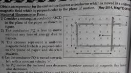
Page 1 :
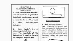
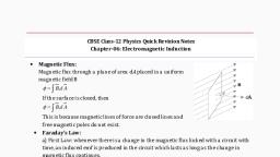
CHAPTER 6, ELECTROMAGNETIC, INDUCTION, 1. Define electromagnetic induction., Ans: Whenever the magnetic flux, linked with a coil changes, an emf, is induced in the coil. This process, is, , called, , electromagnetic, , induction., , 2., State Faraday’s law of, electromagnetic induction., Ans: The magnitude of the, induced emf is equal to the rate, of change of magnetic flux., , , , d, dt, , Eddy Currents, 6. What are Eddy currents?, Ans: Whenever the magnetic flux, liked with a metallic block changes, an, e.m.f. is induced in it. And due to this, e.m.f. circulating currents are, produced in the metallic block. These, circulating currents are called eddy, currents., , ϕ is, , the magnetic flux., 3., , The magnetic flux linked with a, , loop placed in field is given by, ϕ = 6t2 + 7t + 1, where t is in seconds, and ϕ is in milliweber. How much emf, will be induced at t = 2s?, 4. State Lenz’s law., Ans:, The direction of the, induced e.m.f. is always such as, to oppose the rate of change of, magnetic flux., , , , d, dt, , The negative sign shows that, induced emf opposes the change of, flux., Lenz’s law gives the direction of, induced e.m.f., 5. The current passing through the, wire AB is increasing. In which, direction does the induced current, flow in the loop?, , The direction of eddy currents also is, given by Lenz’s law., 7. What are the disadvantages of, eddy currents?, Ans: Eddy currents are undesirable, in, most of the electrical devices like, transformer, induction coil, choke coil, etc. Eddy currents produce heating in, these devices, which is a wastage of, energy., 8., How can you minimize eddy, currents?, Ans: Eddy currents can be minimized, by increasing the resistance of the, metal. This can be done by using, laminated thin sheets of metal,, instead of a single metallic block., , SAJU K JOHN, M.Sc. Physics, NET, PhD Research Scholar at NIT Calicut, , 1
Page 2 :
9. What are the practical uses of, eddy currents?, Ans: The main applications of eddy, currents are the following:, (i) Electromagnetic damping, In a moving coil galvanometer when, the coil oscillates in the m.f. eddy, currents are set up in the frame (core), according to Lenz’s law. These eddy, currents oppose the oscillations and, damping is produced very quickly., This helps for quick measurements., (ii), Induction furnace, The metal to be heated is placed in a, rapidly varying magnetic field, produced by a high frequency AC. The, eddy currents set up in the metal, produce so much heat that the metal is, melted., (iii) Electric brakes (Brakes of, train), A strong magnetic field is applied, across a metallic drum rotating with, the axis of the train. The force, developed due to the eddy currents is, proportional to the speed of the train., So the breaking effect is smooth., (iv) Induction motor, In the induction motor a rotating m.f. is, produced with the help of two single, phase A.C. Which have a phase, difference of, , , 2, , . A metallic cylinder is, , pivoted between the electromagnets., When the m.f. is rotated eddy currents, are developed in the cylinder. To, reduce the relative motion, the cylinder, also rotates with the rotating m.f., (v) Speedometer, In the speedometer an aluminium drum, rotates according to the speed of the, , vehicle. The aluminium drum is, carefully pivoted and a magnet is, placed inside it. As the vehicle moves, the magnet rotates, the eddy currents, are produced in the aluminium drum., These eddy currents try to reduce the, relative motion. For this, the cylinder, also rotates with the magnet. The, pointer of the speedo meter moves, according to the rotation of the drum., 10. An aluminium ring is placed, around the projecting core of a, powerful electromagnet as shown in, the figure below. When the circuit is, closed the ring jumps up to a, surprising height. Why?, , 11[Q]. The motion of copper plates is, damped when it is allowed to, oscillate between the two poles of a, magnet. If slots are cut in the, how, will the damping be affected?, Self Induction, 12. What is Self induction, Ans: When the current through a, coil changes, an e.m.f. is induced, in it. This is called self induction, , SAJU K JOHN, M.Sc. Physics, NET, PhD Research Scholar at NIT Calicut, , 2
Page 3 :
ϕαI, , ϕ= LI, L is called self inductance of the coil or, coefficient of self induction, According to Lenz’s law., ε=, =, , d , dt, d(LI), dt, , dI, dt, , turns are doubled (without any, change in its length), what is its new, self-inductance?, , = 1A /s, , The self inductance of a coil is, as, , the, , induced, , 18. Current in a circuit falls from 5A, to 1A in 0.1 second. If an average emf, of 200 volts is induced, find the self inductance of the coil., , Then, ε= L (numerically), defined, , L = μ0n2Al, , self-inductance L henry. If number of, , 13. Define self-inductance of a, solenoid., dI, Ans: We have ε = L dt, Let, , , , 17. A solenoid of length l metre has, , dI, dt, , ε = L, , Magnetic flux linked with the solenoid., ϕ = BAN, But the m.f. inside the solenoid., B = μ0nI, Therefore,, ϕ = μ0nI AN, , L I = μ0nIAN, , L = μ0nAN, , L = μ0nA(nl), , e.m.f, , developed in the coil when the, rate of change of current through, it is unity., , 19.A plot of magnetic flux(ɸ) versus, , current(I) is shown in the figure for, the two inductors A and B. Which of, the two has larger value of self, inductance?, , 14. What is back emf ?, Ans: The induced emf in a coil, opposes the growth or decay of current, through it. Therefore, it is called back, emf., 15. What is the S.I. unit of selfinductance?, Ans: henry (H), 16. Derive an expression for the, self-inductance of a solenoid., Ans: Consider a solenoid total no. of, turns N, number of turns per unit, length ‘n’ and length l., , 20. Which of the following can, produce maximum induced emf?, (a) 50A, DC, (b) 50A, 50Hz AC, , SAJU K JOHN, M.Sc. Physics, NET, PhD Research Scholar at NIT Calicut, , 3
Page 4 :
k coefficient of coupling, for tight, coupling k = 1, for loose coupling,, k< 1, , (c) 50A, 500Hz AC, (d) 100A, DC, Mutual Induction, 21. Define mutual induction, Ans: When current through a coil, changes an e.m.f. is induced in the, neighboring coil. This is called, mutual induction., , 24. What is tight coupling?, Ans: If the primary and secondary, coils are wound closely in such a way, that the complete flux linked with the, primary is available to the secondary,, then the coupling is called tight, coupling., 25. What is the SI unit of mutual, inductance?, Ans: SI unit of mutual inductance is, henry (H), 26., , ϕ α I1, , ϕ = MI1, Therefore,, ε=, , mutual inductance of 1.5H. If the, current in one coil changes from 0 to, , d2 d, , [MI1], dt, dt, , 20A in 0.5s, (i) what is the change of, , dI, ε = M dt1, 22. Define mutual inductance of two, coils., dI, , Ans: We have, ε = M dt1, Let, , dI1, dt, , as, , the, , induced, , e.m.f, , developed in the secondary coil,, when, , the, , flux linkage with the other coil? (ii), what is the emf induced in the other ?, 27. Derive an expression for the, energy stored in an Inductor., Ans:, , =1, , Then, ε= -M, ε= M (numerically), “Mutual inductance of two coils is, defined, , A pair of adjacent coils has a, , rate, , of, , change, , of, , current through the primary is, unity”., , 23., Give the relation between, mutual inductance and selfinductances., Ans:, M L1L2, M = k L1L2, , When current through a coil, increases, back e.m.f. is developed., This e.m.f. opposes the growth of, current, through, the, circuit., Therefore some work has to be done, by the voltage source to establish a, current in the circuit.This work, done is stored as the energy of the, inductor., Workdone in dt time, dW = Pdt, = εI.dt, , SAJU K JOHN, M.Sc. Physics, NET, PhD Research Scholar at NIT Calicut, , 4
Page 5 :
By Kirchhoff’s voltage rule,, L, , dI, =0, dt, , => ε = L, , ε-, , dI, dt, , Therefore, dW= L, , dI, Idt, dt, , , dW = LIdI, Therefore the total work done in, increasing the current from ‘0’ to I0, is given by,, I0, , W = dW, 0, , 31. Derive an expression for mutual, inductance of two coils., Ans: Consider two coaxial solenoids, S1 and S2 each of length l. Let r1 and r2, be their radii, n1 and n2, the number of, turns per unit length and N1 and N2 the, total number of turns., , I0, , = LIdI, 0, I0, , = L IdI, 0, , =, , I2 , L , 2 0, , I, , 2, , I0, , 02 , , = L 0 , 2, 2, =, , LI 0 2, 2, , W = ½ LI02, Therefore, Energy of the inductor, , 1 2, LI, 2 0, 28. What is the form of energy, stored in an inductor?, Ans: Energy stored in an inductor is in, the form of a magnetic potential energy, UB , , 29. A 50mH coil carries a current of, 2 amperes. Determine the energy, stored in the inductor., 30. Lenz’s Law is a statement of, conservation of energy. Explain, Ans: When a magnet is brought near, to a coil, an induced emf is developed, in the coil. And the coil gets, magnetized so as to oppose the motion, of the magnet. Due to repulsion work, has to be done to bring the coil towards, the magnet. And this work is stored as, energy, in the coil. Here mechanical, energy is converted to electrical, energy., , Let a current I2 flows through S2. Then, the magnetic flux linked with S1 is, Φ1=M12 I2 ---------------- (1), M12 is called the mutual inductance of, the solenoid S1 with respect to the, solenoid S2., Magnetic field due to the current I2 in, the solenoid S2., B2 = μ0n2I2, Then the resulting flux through S1, Φ1=B2A1N1, = μ0n2I2(πr12)(n1 ), , n1 =, , N1, l, , = [μ0n1n2(πr12) ] I2-------------(2), Comparing equations (1) and (2), M12= μ0n1n2(πr12), If we consider the reverse case, we can, show that, , M21 = μ0n1n2πr12, Thus M21 = M12 = M, 32. Define magnetic flux, Ans:, Magnetic flux B A =BAcosθ, where θ is the angle between magnetic, field and normal to the plane of the, coil., , SAJU K JOHN, M.Sc. Physics, NET, PhD Research Scholar at NIT Calicut, , 5
Page 6 :
33. What is the SI unit of magnetic, flux?, Ans: S.I. unit of magnetic flux is, weber (Wb)., Magnetic flux is a scalar quantity., 34. What is motional emf? Derive an, expression for motional emf., Ans: Consider a rectangular frame, MSRN in which the conductor PQ can, move, in the r m.f. directed inwards, the plane of paper., , Ans: Stretch the 3 fingers in, the right hand in 3 mutually r, directions. If the forefinger, gives the directions of magnetic, field and the thumb gives the, direction of motion of the, conductor, then the middle, finger will give the direction of, the induced emf., 36. A jet plane is travelling towards, west at a speed of 1800km/h. What is, the voltage difference developed, between the ends of the wing having, a span of 25m, if the earth’s magnetic, field at the location has a magnitude, , The straight conductor PQ is moved, towards the left with a constant, velocity v perpendicular to the uniform, magnetic field B., The magnetic flux linked with the, rectangular loop PQRS., Φ=BA = B(lx), As PQ moves the value of ‘x’, changes, there by changing the, magnetic flux. Whenever the magnetic, flux changes, an emf is induced., Induced e.m.f., , d , , ε = dt, =, , of 5x 10⁻⁴T and dip angle is 30o., , 37., Explain, the, principle,, construction and working of an A.C., Generator., Ans:, Construction, An ac generator consists of:, (i), , Field magnet, , (ii), , Armature, , (iii), , Slip rings, , (iv), , Brushes, , d(Blx), dt, , dx, = Bl dt, dx, , ε = Bl dt, , ε = Blv, The induced e.m.f., ε = Blv is called, the motional e.m.f., The direction of motional emf is given, by Flemming’s right hand rule., 35. State Flemming’s right hand, rule., SAJU K JOHN, M.Sc. Physics, NET, PhD Research Scholar at NIT Calicut, , 6
Page 7 :
emf is induced in the coil. The ends of, the coil are connected to external, circuit by means of slip rings and, brushes., 38. Why a.c. is preferred for all, commercial purposes?, Ans: This is because a.c. voltage can, be easily converted from one voltage to, another using transformer. At the, transmitting station current is reduced, to a very small value using step up, transformer. This is to reduce I2R loss, while transmitting through the power, lines. At the places of distribution the, current is increased to the required, value using step down transformers., , Principle, A.C. generator works on the, principle, of, electro-magnetic, induction. In a generator mechanical, energy is converted in to electric, energy, When the armature coil rotates, between the pole pieces of field, magnet, the effective area of the coil is, A cos θ, where θ is the angle between, A and B., The flux at any time is ϕ=BAN cosθ, => ϕ= BAN cos ωt, Where ω is the angular velocity, of the coil., The induced e.m.f., ε=, , d , dt, , d, = N dt (BA cos t), = -NAB × -sin ωt × ω, , 39., Match the devices and the, principle behind the working of the, following devices., AC generator, Self-Induction, Choke Coil, Mutual, Induction, Transformer, Speedometer of, Vehicles, Eddy Currents, Electromagnetic, Induction, Ans:, , AC generator, Choke Coil, Transformer, Eddy Currents, , Electromagnetic, Induction, Self-Induction, Mutual, Induction, Speedometer of, Vehicles, , ε = NABω sin ωt, When sin ωt = +1 or -1, ε = NABω (numerically), which is the, maximum value of induced emf. I.e.,, when ωt = 900 or 2700, the change of, flux is maximum., When the armature coil is, mechanically rotated in a uniform, magnetic field, the magnetic flux, through the coil changes and hence an, , SAJU K JOHN, M.Sc. Physics, NET, PhD Research Scholar at NIT Calicut, , 7