Notes of BTech 2nd Sem Agriculture, Workshop Practice Welding - Study Material
Page 1 :
WELDING
Page 2 :
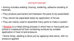
Welding is the process of joining two metallic, pieces together in permanent manner. Heat and/or, pressure is applied to get the joint., •Gas welding, •Arc welding, •Resistance welding, •Solid state welding
Page 3 :
HISTORY OF WELDING….., •Began when people found they could shape rocks by chipping them with, other rocks, •Copper probably first metal to be worked, Ductile (easily hammered, bent or drawn), In Egypt as early as 4000 B.C. and USA before 2000 B.C., •Welding began more than 3000 years ago, •Bronze developed between 3000 and 2000 B.C.
Page 4 :
•Iron became known to Europe about 1000 B.C., , •Working of metals followed one another in great ancient civilizations, Copper, bronze, silver, gold, and iron, •Chinese developed ability to make steel from wrought iron in 589 A.D., • Belgians responsible for progress with steel in Europe, • Japan manufactured steel by repeated welding and forging and, controlling amount of carbon by use of fluxes
Page 5 :
•Industrial Revolution in the middle of the eighteenth century brought, many improvements, •Working of dies and molds became commonplace by beginning of, nineteenth century
Page 6 :
Early Developments in Welding, Edmund Davy discovered acetylene at beginning of nineteenth century, Sir Humphrey Davy discovered the electric arc in 1801, Workable electrical generating devices invented and developed on, practical basis by 1850
Page 7 :
Bare Metal Electrode Welding, Introduced in 1888 by N. G. Slavianoff (Russian), Discovery first recognized in western Europe in 1892, C. L. Coffin was pioneer of welding industry in United States, , 1889 received patent on equipment and process for flash-butt, welding, 1890 received additional patents for spot welding, In 1908, Benardos patented electroslag process of welding thick, plates in one pass
Page 8 :
Welding Associations, •, •, •, •, •, , American National Standards Institute (ANSI), American Petroleum Institute (API), American Society of Mechanical Engineers (ASME), American Welding Society (AWS), American Bureau of Shipping (ABS)
Page 9 :
Welding is joining two pieces of metal by:, • Heating to temperature high enough to cause softening, or melting, • With or without application of pressure, , • With or without use of filler metal
Page 10 :
ELEMENTS OF WELDING PROCESS, • FILLER MATERIAL, Filler materials are used to fill the space between the welded joint., , Filler material is melted and added to the joint during the welding process., It adds strength to the joint.
Page 11 :
FLUXESis a cleaning agent used to avoid the contamination of welded joint, , by impurities like oxides, by oxygen combined with metal during welding., , Flux dissolve oxide, trapped gases and slag(impurities) from base metal.
Page 12 :
WELD POOL dime-sized workable portion of a weld where the base metal has, reached its melting point and is ready to be infused with filler material., , Weld pool is central to the success of the welding process., , Weld pool solidifies to become weld beed.
Page 14 :
WELDING
Page 15 :
Classification of Manufacturing Processes
Page 16 :
Classification of Joining Processes
Page 17 :
Different Welding Processes
Page 18 :
Five basic joint designs
Page 19 :
Four basic types of fusion welds
Page 20 :
Five Welding Positions, Arrow shows the direction of, motion of the electrode / torch., The torch is held approximately, normal to this direction.
Page 22 :
Classification of Welding
Page 23 :
Terminology in welding, •Traverse rate : velocity of the welding source : m/s, •Heat Input : ratio of power to velocity : J/m, •Rate of heat input or heat intensity : W/m2, •Heat intensity distribution
Page 24 :
Arc Welding (AW), A fusion welding process in which coalescence of the metals is, achieved by the heat from an electric arc between an electrode and, the work, , Energy from the arc produces temperatures ~ 10,000 ͦ F (5500ᵒ C),, hot enough to melt any metal, Most AW processes add filler metal to increase volume and strength, of weld joint
Page 25 :
ELECTRIC ARC ?, An electric arc is a discharge of electric current across a gap in a, circuit, , It is sustained by an ionized column of gas (plasma) through which, the current flows, , To initiate the arc in AW, electrode is brought into contact with work, and then quickly separated from it by a short distance
Page 26 :
Two Basic Types of AW Electrodes, • Consumable, o consumed during welding process, o Source of filler metal in arc welding, , • Nonconsumable, o not consumed during welding process, o Filler metal must be added separately if it is added
Page 27 :
Arc Shielding, •At high temperatures in AW, metals are chemically reactive to, oxygen, nitrogen, and hydrogen in air, Mechanical properties of joint can be degraded by these reactions, To protect operation, arc must be shielded from surrounding air in, AW processes, , •Arc shielding is accomplished by:, Shielding gases, e.g., argon, helium, CO2, Flux
Page 28 :
Flux, • A substance that prevents formation of oxides and other, contaminants in welding, or dissolves them and facilitates removal, , Provides protective atmosphere for welding, Stabilizes arc, Reduces spattering
Page 29 :
Various Flux Application Methods, • Pouring granular flux onto welding operation, • Stick electrode coated with flux material that melts during welding to, cover operation, • Tubular electrodes in which flux is contained in the core and released, as electrode is consumed
Page 30 :
Power Source in Arc Welding, Direct current (DC) vs. Alternating current (AC), • AC machines less expensive to purchase and operate, but generally, restricted to ferrous metals, • DC equipment can be used on all metals and is generally noted for, better arc control
Page 36 :
Consumable Electrode, AW Processes, , • Shielded Metal Arc Welding (SMAW), • Gas Metal Arc Welding (GMAW), • Flux-Cored Arc Welding (FCAW), • Electrogas Welding, , • Submerged Arc Welding (SAW)
Page 37 :
Shielded Metal Arc Welding (SMAW), Uses a consumable electrode consisting of a filler metal, rod coated with chemicals that provide flux and shielding, , Sometimes called "stick welding"
Page 39 :
Welding Stick in SMAW, • Composition of filler metal usually close to base metal, • Coating: powdered cellulose mixed with oxides and carbonates, and held, together by a silicate binder, , • Welding stick is clamped in electrode holder connected to power source, Disadvantages of stick welding:, Sticks must be periodically changed, High current levels may melt coating prematurely
Page 40 :
SMAW Applications, Used for steels, stainless steels, cast irons, and certain, nonferrous alloys, Not used or rarely used for aluminum and its alloys,, copper alloys, and titanium
Page 41 :
Gas Metal Arc Welding (GMAW) or MIG, • Uses a consumable bare metal wire as electrode with shielding by, flooding arc with a gas, • Wire is fed continuously and automatically from a spool through the, welding gun, • Shielding gases include argon and helium for aluminum welding, and, CO2 for steel welding, • Bare electrode wire plus shielding gases eliminate slag on weld bead
Page 43 :
GMAW Advantages over SMAW, •, •, •, •, •, •, •, , Better arc time because of continuous wire electrode, Sticks must be periodically changed in SMAW, Better use of electrode filler metal than SMAW, End of stick cannot be used in SMAW, Higher deposition rates, Eliminates problem of slag removal, Can be readily automated
Page 44 :
Flux-Cored Arc Welding (FCAW), Adaptation of shielded metal arc welding, to overcome limitations of, stick electrodes - two versions, Self-shielded FCAW - core includes compounds that produce, shielding gases, Gas-shielded FCAW - uses externally applied shielding gases, , Electrode is a continuous consumable tubing (in coils) containing flux, and other ingredients (e.g., alloying elements) in its core
Page 45 :
Flux-Cored Arc Welding, Presence or absence of externally supplied shielding gas distinguishes:, (1) self-shielded - core provides ingredients for shielding,, (2) gas-shielded - uses external shielding gases
Page 47 :
Submerged Arc Welding (SAW), • Uses a continuous, consumable bare wire electrode, with arc shielding, by a cover of granular flux, , • Electrode wire is fed automatically from a coil, • Flux introduced into joint slightly ahead of arc by gravity from a hopper, • Completely submerges operation, preventing sparks, spatter, and, radiation
Page 48 :
SAW
Page 50 :
SAW Applications, •, •, •, •, •, , Steel fabrication of structural shapes (e.g., I-beams), Seams for large diameter pipes, tanks, and pressure vessels, Welded components for heavy machinery, Most steels (except hi C steel), Not good for nonferrous metals
Page 51 :
ELECTROSLAG WELDING, , This initial charge heats a layer of loose flux that becomes molten and, extinguishes the arc.
Page 53 :
TIG WELDING or GTAW, , Typical flow rate of shielding inert gas may vary from 5-50 liters/min.
Page 58 :
PROPERTIES OF ELECTRODES, SHIELDING GAS, AND FLUX, , • Consumable electrodes materials are selected such that finished weld, metal should have similar mechanical properties that of base metal, with no defects,, Consumable Electrodes contains de-oxidising metals (Si, Mn, Ti,, Al) and de-nitriding metals (zirconium) in small percentages to, prevent entrapment of oxygen and nitrogen in the weld, reducing the, porosity and giving continuous weld., • Shielding gas is necessary to protect weld area from atmospheric, gases, thereby reducing porosity and cracking., EG. argon, helium, carbon dioxide etc, • Flux when melted by the arc, mixes with the impurities in the weld, pool and forms slag and covers the weld pool from contamination., E.G. lime, silica, manganese dioxide, calcium flouride etc, flux is either coated on the electrode surface, or inside the, electrode, or provided additionally(non-consumable electrodes).
Page 59 :
GAS WELDING
Page 63 :
• Gas welding is a fusion welding process., • Acetylene burned in oxygen is used as source of heat. This heat is used to fuse the metal joints., ADVANTAGES, 1. Simple, 2. Portable, 3. Easy maintenance, , 1., 2., 3., 4., , DISADVANTAGES, Very low welding speed,, Large amount of heat is required, some amount of heat is wasted, since heat is distributed, over a large area., large heat affected zones., Should not be used with reactive metals like Titanium and Zirconium.
Page 64 :
TYPES OF FLAMES
Page 78 :
WELD DEFECTS, , • WELD SPATTER-, , Caused by a long arc length, very high current, or a phenomenon called, arc blow (electric arc being deflected away from the weld pool by, magnetic forces)., Damages appearance of the weld and increases cleaning cost., , • POROSITYCaused due to arc blow, • POOR FUSION-, , Caused by low current, contaminated joint surface, improper electrode, • SHALLOW PENETRATION –, Caused by decreased melting of electrodes. This can be prevented by, decreasing weld speed, increasing the current , using smaller electrodes, • CRACKINGHigh carbon content, high allow content, high sulphur content and, Excessive restraining of base metal which causes internal stress inside, the weld, which leads to cracking when cools down or contracts.
Page 79 :
TYPES OF WELD JOINTS, , BUTT JOINT, CORNER JOINT, LAP JOINT, TEE JOINT, EDGE JOINT
Page 80 :
FLANGE WELDS AND SURFACING WELDS
Page 81 :
GROOVE WELDS
Page 82 :
CONSUMABLE TYPE, ELECTRODE WELDING, , ELECTRODE, HOLDER, , Electrode is made anode, (high heat concentration), to melt more and, penetrate the joint fast, , POWER SUPPLY, STEP DOWN, TRANSFORMER, , SHIELDING GAS, PROTECTION, Flux mixes with, the impurities, and rises to top, of weld pool, , low voltage , short arc length, , High current , faster melting, , Base metal is, made cathode(-), , HEAT, AFFECTED, AREA, , filler metal, mixed with, molten metal, and penetrates, the joint, , WELD POOL
Page 83 :
NON-CONSUMABLE TYPE, ELECTRODE WELDING, , FILLER ROD, , ELECTRODE HOLDER, Electrode is made, cathode (-)to prevent, electrode melting, , POWER SUPPLY, STEP DOWN, TRANSFORMER, Low voltage , Short arc length, , SHIELDING GAS, PROTECTION, Flux mixes with, the impurities, and rises to top, of weld pool, , filler metal, mixed with, molten metal, and penetrates, the joint, , high current, Faster melting, Base metal is made, anode (high heat, concentration), , HEAT, AFFECTED, AREA, , WELD POOL
Page 86 :
METAL INERT GAS WELDING, DISADVANTAGES, METALS, • MIG is a semi-automatic, or automatic,, since itAPPLICATIONS, uses constant, 1. Speed due to, 1. cannot be used in, 1. welding metals, automobile industries., voltage(arc, continuously fed length), areassupply., of high air, with high thermal, filler electrodes, Because conductivities like, • consumable, wiremovement,, acting, as bothaluminium, electrode, and filler metal, of the need to, and, is continuously fed,, maintain a stable, other nonshroud of shielding, ferrous, steels., • inert or semi-inert, gasshielding gas like carbon dioxide flowed, 2. to, Pority, of the welded, around the wire, protect, the weld site from, because, contamination. joints, solidification of the, weld, pool, takes source is most commonly used, • Constant voltage,, DC, power, place before the, with GMAW, but escape, constant, current alternating current are, of entrapped, gas., used as well., ADVANTAGES, , 3. Forms Solid impure, Aluminium dross, floating on the weld, pool, 4. complicated, equipment
Page 87 :
FLUX-CORED ARC WELDING, • Flux-cored arc welding (FCAW or FCA) is a, semi-automatic or automatic arc, welding process., • Tubular consumable electrode containing, a flux which provides necessary protection, from the atmosphere and metal impurities, is, continuously-fed to weld point., • constant-voltage or, less commonly, a, constant-current welding power supply., • An externally supplied shielding gas is, sometimes used
Page 89 :
ADVANTAGES, 1., 2., 3., 4., , All position welding, high welding speed, Portability, thicker and out-ofposition metals, 5. higher production, rate, 6. fewer weld defects, 7. slag is also easy to, remove, , DISADVANTAGES, , METALS, , 1. cannot be used in a, 1. Alloy steels, windy environment, 2. Nickel alloys, 2. excessive, noxious, smoke (making it, difficult to see the weld, pool), 3. Skilled operation, 4. Contact tip melting,, preventing flux flow., 5. Costly electrode, 6. Irregular wire feed, , APPLICATIONS, 1. Construction, 2. Automotive industries
Page 90 :
SUBMERGED ARC WELDING, • Arc, is struck beneath, a covering layer of granular, ADVANTAGES, DISADVANTAGES, METALS flux, APPLICATIONS, • The flux starts depositing on the joint to be welded, No is, weld, 1. Limited, flatmelted, 1. Steels, 1. Structural, and, •1.Flux, insulator when, cold, to, once, by arc, it becomes, conductive, spatters, horizontal between, 2. Nickel, alloys electrode, ship/barge, and, current flow is maintained, consumable, and, 2.base, No fumes, constructions, metal through surfaces, the molten metal., 3. No visible, 2. Non visibility of, • The, upper, portion, ofprocess., the flux in contact with the atmosphere and, spark, remains in granular shape and can be reused, 4. High welding, • Lower, speedportion melts and becomes slag, and must be removed after, 5.welding., Deep weld, penetration for, thick plates, 6. Suitable for, indoor and, outdoor work, 7. Minimal weld, defect
Page 91 :
TUNGSTEN INERT GAS WELDING, • Uses non-consumable tungsten electrode., ADVANTAGES, DISADVANTAGES, METALS, APPLICATIONS, •1.Great, Weldcontrol, areaover, is protected, by inert gases, 1. Complex, 1. Stainless steel, 1. Aerospace, weld, area need to manually, 2. More operator, 2. Aluminium, industryboth, • Welder, feed the filler, metal, which required, 2. Strong high quality, skill, 3. magnesium, 2. Space vehicles, hand., welds., 3. Slower process, 4. Zinc and alloys, 3. Bycycle industry, 3., not is, in struck, 4. Manual, Naval, aplications, • Filler, Oncemetal, theisarc, the filler, welder moves the torch in a 4., small, circle, to, direct, contact, with, metal, feed metal is then added manually into the, create, a welding, pool., Filler, the arc, so no filller, 5. Difficult to, molten, weld, pool, but, away from the arc., metal is wasted by, maintain short arc, vaporization, • Filler metal and, , length is advanced to the weld pool alternatively, electrode, Ultra-violet, while keeping the6.filler, metal inside the shielding gas., radiation, 7. Formation of, ozone due to arc, plasma, 8. If current exceeds,, tungsten inclusion, may take place in, the base metal.
Page 92 :
CONSUMABLE ELECTRODE, , FLUX SUPPLY, , CONSUMABLE GUIDE TUBE, , ELECTRODE WIRE SPOOL, FOR CONTINUOUS FILLER FEED, , ELECTRO –SLAG, WELDING, SCHEMATIC, VERTICAL JOINT
Page 93 :
ELECTRO SLAG WELDING, METALS, • ADVANTAGES, Electric arc isDISADVANTAGES, struck in the base, metal joint atAPPLICATIONS, a desired, 1. point., Single pass, is 1., Restricted, to 1. Cast iron, 1. Ship building, Then, flux, is added, sufficient, vertical, 2. Aluminium, 2. Building Construction, •2. This, the joint. 3. Machine frames, Thick flux then melt, positionand fills, 3. Magnesium, materials, 2. High heat, 4. Copper, 4. Heavy pressure vessels, •3. Flux, is, added, until, molten, slag, rises, and, extinguishes the, High filler, input leads to 5. titanium, 5. Joining turbine casting, arc., metal, poor weld, utilization, quality., •4. But, current will still be flowing through the molten flux and, No weld, still, hot due to electrical resistance., spatter,, because no, • Filler, arc metal is then continuously fed into this molten slag, 5. through, Skilled, a consumable guide tube and molten filler metal, operators, not, then, fills, the joint.., required, 6. Minimum, joint, preparation, and cleaning
Page 94 :
PLASMA ARC WELDING, • Similar to TIG, • But Tungsten Electrode is positioned inside the torch body, and not exposed., • Electric arc is struck between non-consumable electrode and, work piece., • This ionizes the inert gas flowing through the nozzle and his, ionized high velocity plasma is then used to melt the base, metal and filler metal., • Two inert gases are used, one to ionize, and other as, shielding gas
Page 96 :
STEP, 3:, 1:, 2:, STEP, 5:, STEP 4:, 6:, Heat, thethe, refractory, coating, joint, toisbe, weld, with, a metal, boxisbox, Enclose, solidified, wax, with, another, Place, barrel, containing, The mixture, is ignited, and, Refractory, coating, then, removed, and metal, joint, allowed to solidify, Wax, melts, and, flows, down, creating, a cavity, inside, refractory, the, joint, with, molten, wax, and, allow, the wax, to the, solidify, Fill, gap, with, aon, refractory, material, thermite, mixture, the, thermite, reaction, takes, Extra, metal, is, then, removed, by, grinding, coating, Remove, the box coating, top, of to, refractory, place, form, Cover, the, bottom, part of refractory cavity with a plug, To, initiate, the, thermite, molten, iron, and, reaction,, mixture, aluminium, oxide. should, be, ignited, Iron, being denser than, Fe2 O3 + Al Fe + Al2O3 + heat, For, this an ignition, wire, aluminium, oxide will, be is, inserted, into the, at the bottom, of mixture, the, barrel, This molten iron then fills, the refractory cavity, , WAX, , THERMITE, WELDING
Page 97 :
PRESSURE WELDING METHODS
Page 98 :
FRICTION, WELDING
Page 99 :
TYPES OF FRICTION WELDING PROCESSES
Page 100 :
FRICTION STIR WELDING
Page 102 :
RESISTANCE WELDING, Resistance welding process makes use of the electrical resistance for, generating heat required for melting the workpiece. It is generally used for, , joining thin plates and structures. It has different variants such as Seam, welding, Projection welding and Spot welding.
Page 110 :
ADVANTAGES OF RESISTANCE WELDING
Page 111 :
DISADVANTAGES OF RESISTANCE WELDING
Page 112 :
RESISTANCE SEAM WELDING, , Seam consists of, a, series, of, overlapping spot, welds.
Page 121 :
UPSET WELDING/BUTT WELDING
Page 122 :
HOW TO, ACHIEVE, HEAT, BALANCE
Page 123 :
PERCUSSION WELDING
Page 124 :
PERCUSSION WELDING, PROCESS IN WHICH HEAT IS PRODUCED FROM AN, ARC THAT IS GENERATED BY THE RAPID DISCHARGE OF, ELECTRICAL ENERGY BETWEEN THE WORKPIECES AND, FOLLOWED BY IMMEDIATELY BY AN IMPACTING FORCE, WHICH WELD THE PIECES TOGETHER
Page 125 :
CROSS SECTION OF A TYPICAL FUSION WELDED JOINT, , The fusion zone consists of a mixture of filler metal and base metal that have, completely melted.
Page 126 :
Electrical, , Solid, State, Welding, , Chemical, Friction, Mechanical, , Pressure, , Ultrosonic, Weld
Page 127 :
Ultrasonic welding (USW), Moderate pressure is applied between the two parts, and an oscillating motion at ultrasonic frequencies, is used in a direction parallel to the contacting, surfaces. The combination of normal and vibratory, forces results in shear stresses that remove surface, films and achieve atomic bonding of the surfaces.
Page 128 :
Definition of Ultrasonic Welding, A solid state welding process in which coalescence is, produced at the faying surfaces by the application of, high frequency vibratory energy while the work pieces, are held together under moderately low static pressure.
Page 129 :
Ultrasonic Welding Process, Process, Description:, • Components, of, ultrasonic welding, system include:, • Transducer, • Sonotrode, • Anvil, , Clamping, force, Mass, , wedge Transducer, , Sonotrode, tip, , Vibration, , Weldment, Anvil, Force
Page 130 :
Ultrasonic Welding Mechanism, • A static clamping force is applied, perpendicular to the interface, between the work pieces., • The contacting sonotrode, oscillates parallel to the interface., • Combined effect of static and, oscillating force produces, deformation which promotes, 10-75 KHz, welding., , Clamping, force, Mass, , wedge Transducer, , Sonotrode, tip, workpiece, Anvil, Force
Page 131 :
ultrasonic, spot-type welding machine, Courtesy AWS handbook
Page 132 :
AWS Welding Handbook
Page 133 :
Advantages of Ultrasonic Welding, • No heat is applied and no melting occurs., • Permits welding of thin to thick sections., • Welding can be made through some surface coatings., • Pressures used are lower, welding times are shorter, and the thickness, of deformed regions are thinner than for cold welding.
Page 134 :
Limitations of Ultrasonic Welding, • The thickness of the component adjacent to the sonotrode tip must not, exceed relatively thin gages because of power limitations of the, equipment., • Process is limited to lap joints., • Butt welds can not be made because there is no means of supporting, the workpieces and applying clamping force.
Page 135 :
SOLDERING, , •Soldering is a process in which two or more metal items are joined, together by melting and flowing a filler metal (solder) into the joint, •the filler metal having a lower melting point than the adjoining, metal., •Soldering differs from welding in that soldering does not involve, melting the work pieces., •In brazing, the filler metal melts at a higher temperature, but in, soldering filler alloy melts at lower temperature than brazing., •Used for low strength applications like electronics and plumbing
Page 137 :
TYPES OF SOLDERS, • Tin Lead solders, • 60% Tin and 40% lead, • 50% Tin and 50% lead, • Tin-Antimony-Lead solders, • Lead Silver solders, • Cadmium Silver Solders
Page 138 :
FLUXES USED FOR SOLDERING, , 1.INORGANIC ACIDS, 2.NON CORROSIVE RESIN BASED FLUXES
Page 139 :
TYPES OF SOLDERING METHODS, , 1. SOLDERING IRON METHOD, 2. DIP AND WAVE METHOD
Page 142 :
BRAZING, , Brazing is a metal-joining process in, which two or more metal items are, joined together by melting and flowing, a filler metal into the joint, the filler, metal having a lower melting point than, the adjoining metal., Brazing differs from welding in that it, does not involve melting the work, pieces and from soldering in using higher, temperatures for a similar process., It is similar to soldering, except the, temperatures used to melt the filler, metal are higher for brazing than, soldering., , Aluminum or copper alloys, are used as filler materials, , A major advantage of brazing is the, ability to join the same or different, metals with considerable strength.
Page 144 :
FILLER METALS IN BRAZING, , 1.ALUMINIUM & SILICON, 2.COPPER & PHOSPHEROUS, 3.COPPER & ZINC
Page 145 :
BRAZING PROCESSES, , 1. TORCH BRAZING, 2. VACUUM BRAZING
Page 151 :
Multipass Welds, Ability to make multipass welds, such as this one, on plate and pipe,, led to growth of industry. Welds are, sound and have uniform appearance.
Page 152 :
•Patent issued in 1930 to Hobart and Devers for use of electric arc, within inert gas atmosphere, , •Tungsten electrode replace magnesium procedure Patent issue in 1942, •Linde Company developed gas tungsten arc welding (GTAW), Also called tungsten inert gas (TIG) process or HELIARC
Page 153 :
An aluminum weld made using, the TIG process., The welding, of aluminum is no longer a, problem and can be done with, the same ease as that of steel.
Page 154 :
HIGH ENERGY BEAM WELDING, - ELECTRON BEAM WELDING, , - LASER BEAM WELDING
Page 155 :
ELECTRON BEAM WELDING, EBW set up, , a) Electron gun,, b) Power supply,, c) Vacuum Chamber,, d) Work piece handling device
Page 164 :
RUBY LASER
Page 165 :
LASER WELDED RAZOR BLADE
Page 166 :
WELDING DEFECTS
 Learn better on this topic