Page 1 :
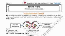
Unit 3: Gear Trains, , T. Y. BTech (Mech), , Content, Velocity ratios, Types of gear trains, Tooth load, Torque transmitted and holding torque., , 3.1 Introduction, Sometimes, two or more gears are made to mesh with each other to transmit, power from one shaft to another. Such a combination is called gear train or train of, toothed wheels. The nature of the train used depends upon the velocity ratio required and, the relative position of the axes of shafts. A gear train may consist of spur, bevel or, spiral gears., , 3.2 Types of gear trains, Following are the different types of gear trains, depending upon the arrangement of, wheels:, A. Simple gear train,, , B. Compound gear train,, , C. Reverted gear train, D. Epicyclic gear train, In the first three types of gear trains, the axes of the shafts over which the gears, are mounted are fixed relative to each other. But in case of epicyclic gear trains, the axes, of the shafts on which the gears are mounted may move relative to a fixed axis., A. Simple Gear Train, When there is only one gear on each shaft, as shown in Fig. 3.1, it is known as, simple gear train. The gears are represented by their pitch circles. When the distance, between the two shafts is small, the two gears 1 and 2 are made to mesh with each other, to transmit motion from one shaft to the other, as shown in Fig. 3.1 (a). Since the gear 1, drives the gear 2, therefore gear 1 is called the driver and the gear 2 is called the driven, or follower. It may be noted that the motion of the driven gear is opposite to the motion, of driving gear., , Fig.3.1. Simple gear train, Prof. Sachin M. Shinde,KECSP, , Page 1
Page 2 :
Unit 3: Gear Trains, , T. Y. BTech (Mech), , Let, N1 = Speed of gear 1(or driver) in r.p.m.,, N2 = Speed of gear 2 (or driven or follower) in r.p.m.,, T1 = Number of teeth on gear 1, and, T2 = Number of teeth on gear 2., Since the speed ratio (or velocity ratio) of gear train is the ratio of the speed of, the driver to the speed of the driven or follower and ratio of speeds of any pair of gears, in mesh is the inverse of their number of teeth, therefore, Speed ratio =, It may be noted that ratio of the speed of the driven or follower to the speed of the driver, is known as train value of the gear train. Mathematically,, Train value =, From above, we see that the train value is the reciprocal of speed ratio., Sometimes, the distance between the two gears is large. The motion from one gear to, another, in such a case, may be transmitted by either of the following two methods:, 1. By providing the large sized gear, or 2. By providing one or more intermediate gears., A little consideration will show that the former method (i.e. providing large sized, gears) is very inconvenient and uneconomical method; whereas the latter method (i.e., providing one or more intermediate gear) is very convenient and economical., It may be noted that when the number of intermediate gears are odd, the motion of both, the gears (i.e. driver and driven or follower) is like as shown in Fig. 3.1 (b).But if the, number of intermediate gears are even, the motion of the driven or follower will be, in the opposite direction of the driver as shown in Fig. 3.1 (c).Now consider a simple, train of gears with one intermediate gear as shown in Fig.3.1 (b)., Let, N1 = Speed of driver in r.p.m.,, N2 = Speed of intermediate gear in r.p.m.,, N3 = Speed of driven or follower in r.p.m.,, T1 = Number of teeth on driver,, T2 = Number of teeth on intermediate gear, and, T3 = Number of teeth on driven or follower., Since the driving gear 1 is in mesh with the intermediate gear 2, therefore speed ratio for, these two gears is, ………………………..(i), , Prof. Sachin M. Shinde,KECSP, , Page 2
Page 3 :
Unit 3: Gear Trains, , T. Y. BTech (Mech), , Similarly, as the intermediate gear 2 is in mesh with the driven gear 3, therefore speed, ratio for these two gears is, ………………………..(ii), The speed ratio of the gear train as shown in Fig. 3.1 (b) is obtained by multiplying the, equations (i) and (ii)., , i.e. Speed ratio =, , =, , and Train value =, , =, , Similarly, it can be proved that the above equation holds good even if there are, any number of intermediate gears. From above, we see that the speed ratio and the train, value, in a simple train of gears, is in-dependent of the size and number of inter-mediate, gears. These intermediate gears are called idle gears, as they do not affect the speed ratio, or train value of the system. The idle gears are used for the following two purposes:, 1. To connect gears where a large centre distance is required, and, 2. To obtain the desired direction of motion of the driven gear (i.e. clockwise or, anticlockwise)., B. Compound Gear Train, When there is more than one gear on a shaft, as shown in Fig. 3.2, it is called a, compound train of gear. We have seen in simple gear train that the idle gears, in a simple, train of gears do not affect the speed ratio of the system. But these gears are useful in, bridging over the space between the driver and the driven But whenever the distance, between the driver and the driven or follower has to be bridged over by intermediate, gears and at the same time a great ( or much less ) speed ratio is required, then the, advantage of intermediate gears is intensified by providing compound gears on, intermediate shafts., In this case, each intermediate shaft has two gears rigidly fixed to it so that they, may have the same speed. One of these two gears meshes with the driver and the other, with the driven or follower attached to the next shaft as shown in Fig.3.2., In a compound train of gears, as shown in Fig. 13.2, the gear 1 is the driving gear, mounted on shaft A, gears 2 and 3 are compound gears which are mounted on shaft B., Prof. Sachin M. Shinde,KECSP, , Page 3
Page 4 :
Unit 3: Gear Trains, , T. Y. BTech (Mech), , The gears 4 and 5 are also compound gears which are mounted on shaft C and the gear 6, is the driven gear mounted on shaft D., , Fig. 3.2. Compound gear train., Let N1= Speed of driving gear 1,, T1 = Number of teeth on driving gear 1,, N2 ,N3 ..., N6 = Speed of respective gears in r.p.m., and, T2 ,T3..., T6 = Number of teeth on respective gears., Since gear 1 is in mesh with gear 2, therefore its speed ratio is, ………………………..(i), similarly, for gears 3 and 4, speed ratio is, ………………………..(ii), and for gears 5 and 6, speed ratio is, ………………………..(iii), The speed ratio of compound gear train is obtained by multiplying the equations (i), (ii), and (iii),, , Prof. Sachin M. Shinde,KECSP, , Page 4
Page 5 :
Unit 3: Gear Trains, , T. Y. BTech (Mech), , Since gears 2 and 3 are mounted on one shaft B, therefore N2 = N3. Similarly gears 4 and, 5 are mounted on shaft C, therefore N4 = N5., Speed ratio =, , =, , Train value =, The advantage of a compound train over a simple gear train is that a much larger, speed reduction from the first shaft to the last shaft can be obtained with small gears. If a, simple gear train is used to give a large speed reduction, the last gear has to be very, large. Usually for a speed reduction in excess of 7 to 1, a simple train is not used and a, compound train or worm gearing is employed., Note: The gears which mesh must have the same circular pitch or module. Thus gears 1, and 2 must have the same module as they mesh together. Similarly gears 3 and 4, and, gears 5 and 6 must have the same module., C. Reverted Gear Train, When the axes of the first gear (i.e. first driver)and the last gear (i.e. last driven, or follower) are co-axial, then the gear train is known as reverted gear train as shown in, Fig. 3.3.We see that gear 1 (i.e. first driver) drives the gear 2 (i.e. first driven or, follower) in the opposite direction. Since the gears 2 and 3 are mounted on the same, shaft, therefore they form a compound gear and the gear3 will rotate in the same, direction as that of gear 2. The gear 3 (which is now the second driver) drives the gear 4, (i.e. the last driven or follower) in the same direction as that of gear 1. Thus we see that, in a reverted gear train, the motion of the first gear and the last gear is like., , Fig 3.3 Reverted gear train, Prof. Sachin M. Shinde,KECSP, , Page 5
Page 6 :
Unit 3: Gear Trains, , T. Y. BTech (Mech), , Let, T1 = Number of teeth on gear 1,, r1 = Pitch circle radius of gear 1, and, N1 = Speed of gear 1 in r.p.m., Similarly,, T2, T3, T4 = Number of teeth on respective gears,, r2, r3, r4 = Pitch circle radii of respective gears, and, N2, N3, N4 = Speed of respective gears in r.p.m., Since the distance between the centers of the shafts of gears 1 and 2 as well as gears 3, and 4 is same, therefore, r1 + r2 = r3 + r4..................... (i), Also, the circular pitch or module of all the gears is assumed to be same; therefore, number of teeth on each gear is directly proportional to its circumference or radius., ∴ *T1 + T2 = T3 + T4............................. (ii), ………………….(iii), , and Speed ratio =, …………………………… (iv), , From equations (i), (ii) and (iii), we can determine the number of teeth on each, gear for the given centre distance, speed ratio and module only when the number of teeth, on one gear is chosen arbitrarily. The reverted gear trains are used in automotive transmissions, lathe back gears, industrial speed reducers, and in clocks (where the minute, and hour hand shafts are co-axial)., D. Epicyclic Gear Train, , Fig 3.4 Epicyclic gear train, We have already discussed that in an epicyclic gear train, the axes of the shafts,, over which the gears are mounted, may move relative to a fixed axis. A simple epicyclic, gear train is shown in Fig. 3.4, where a gear A and the arm C have a common axis at O1, Prof. Sachin M. Shinde,KECSP, , Page 6
Page 7 :
Unit 3: Gear Trains, , T. Y. BTech (Mech), , about which they can rotate. The gear B meshes with gear A and has its axis on the arm, at O2, about which the gear B can rotate. If the arm is fixed, the gear train is simple and, gear A can drive gear B or vice- versa, but if gear A is fixed and the arm is rotated about, The axis of gear A (i.e. O1), then the gear B is forced to rotate upon and around gear A., Such a motion is called epicyclic and the gear trains arranged in such a manner that one, or more of their member’s moves upon and around another member are known as, epicyclic gear trains (epi. means upon and cyclic means around). The epicyclic gear, trains may be simple or com-pound. The epicyclic gear trains are useful for transmitting, high velocity ratios with gears of moderate size in a comparatively lesser space. The, epicyclic gear trains are used in the back gear of lathe, differential gears of the, automobiles, hoists, pulley blocks, wrist watches etc., , 3.3 Velocity Ratio of Epicyclic Gear Train, The following two methods may be used for finding out the velocity ratio of an epicyclic, gear train., 1. Tabular method, and 2. Algebraic method., These methods are discussed, in detail, as follows:, 1. Tabular method. Consider an epicyclic gear train as shown in Fig. 3.5., , Fig 3.5 Epicyclic gear train, Let TA = Number of teeth on gear A, and, TB = Number of teeth on gear B., First of all, let us suppose that the arm is fixed. Therefore the axes of both the, gears are also fixed relative to each other. When the gear A makes one revolution, anticlockwise, the gear B will make (TA / TB) revolutions, clockwise. Assuming the, anticlockwise rotation as positive and clockwise as negative, we may say that when gear, A makes + 1 revolution, then the gear B will make (– TA / TB) revolutions. This, Prof. Sachin M. Shinde,KECSP, , Page 7
Page 8 :
Unit 3: Gear Trains, , T. Y. BTech (Mech), , statement of relative motion is entered in the first row of the table (see Table, 3.1).Secondly, if the gear A makes+ x revolutions, then the gear B will make (– x × TA /, TB ) revolutions. This Statement is entered in the second row of the table. In other, words, multiply he each motion (entered in the first row) by x., Thirdly, each element of an epicyclic train is given + y revolutions and entered in the, third row. Finally, the motion of each element of the gear train is added up and entered, in the fourth row., Table 3.1 Table of motions, Step, , Conditions of motion, , No, 1, , 2, , Revolutions of elements, Arm C, , Arm fixed-gear A rotates through +, 1 revolution i.e. 1 rev. anticlockwise, Arm fixed-gear A rotates through +, x revolutions, , Gear A, , Gear B, , 0, , +1, , -, , 0, , +x, , -x, , 3, , Add + y revolutions to all elements, , +y, , +y, , 4, , Total motion, , +y, , x+y, , +y, +y - x, , A little consideration will show that when two conditions about the motion of rotation, of any two elements are known, then the unknown speed of the third element may be, obtained by substituting the given data in the third column of the fourth row., 2. Algebraic method. In this method,, The motion of each element of the epicyclic train relative to the arm is set down, in the form of equations. The number of equations depends upon the number of elements, in the gear train. But the two conditions are, usually, supplied in any epicyclic train viz., some element is fixed and the other has specified motion. These two conditions are, sufficient to solve all the equations; and hence to determine the motion of any element in, the epicyclic gear train., Let the arm C be fixed in an epicyclic gear train as shown in Fig. 3.5. Therefore speed of, the gear A relative to the arm C, = NA – NC, and speed of the gear B relative to the arm C,, = NB – NC, Since the gears A and B are meshing directly, therefore they will revolve in opposite, directions., Prof. Sachin M. Shinde,KECSP, , Page 8
Page 9 :
Unit 3: Gear Trains, , T. Y. BTech (Mech), , =Since the arm C is fixed, therefore its speed, NC = 0, =If the gear A is fixed, then NA= 0., == 1+, Note: The tabular method is easier and hence mostly used in solving problems on, epicyclic gear train, , 3.4 Compound epicyclic gear train—sun and planet gear, , Fig. 3.6. Compound epicyclic gear train., A compound epicyclic gear train is shown in Fig. 3.6.It consists of two co-axial shafts, S1 and S2, an annulus gear A which is fixed, the compound gear (or planet gear) B-C, the, sun gear D and the arm H. The annulus gear has internal teeth and the com-pound gear is, carried by the arm and revolves freely on a pin of the arm H. The sun gear is co-axial, with the annulus gear and the arm but independent of them. The annulus gear A meshes, with the gear B and the sun gear D meshes with the gear C. It may be noted that when, the annulus gear is fixed, the sun gear provides the drive and when the sun gear is fixed,, the annulus gear provides the drive. In both cases, the arm acts as a follower., Note: The gear at the centre is called the sun gear and the gears whose axes move are, called planet gears., Prof. Sachin M. Shinde,KECSP, , Page 9
Page 10 :
Unit 3: Gear Trains, , T. Y. BTech (Mech), , Let TA , TB , TC , and TD be the teeth and NA, NB, NC and ND be the speeds for the gears, A, B,C and D respectively. A little consideration will show that when the arm is fixed, and the sun gear D is turned anticlockwise, then the compound gear B-C and the annulus, gear A will rotate in the clockwise direction. The motions of rotations of the various, elements are shown in the table below., Table 3.2 Table of motions of Compound epicyclic gear train, Step, , Conditions of motion, , No, , Revolutions of elements, Arm C, , Gear D, , 0, , +1, , -, , -, , 0, , +x, , -x, , -, , +y, , +y, , +y, , x+y, , Compound, gear B-C, , Gear A, , Arm fixed-gear D rotates, 1, , through + 1 revolution i.e. 1, rev. anticlockwise, , 2, , 3, 4, , Arm fixed-gear D rotates, through + x revolutions, Add + y revolutions to all, elements, Total motion, , +y, +y - x, , +y, y--, , 3.5 Torques in epicyclic gear trains, , Fig. 3.7. Torques in epicyclic gear trains, When the rotating parts of an epicyclic gear train, as shown in Fig. 3.7, have no angular, acceleration, the gear train is kept in equilibrium by the three externally applied torques,, viz., 1. Input torque on the driving member (T1),, 2. Output torque or resisting or load torque on the driven member (T2),, , Prof. Sachin M. Shinde,KECSP, , Page 10
Page 11 :
Unit 3: Gear Trains, , T. Y. BTech (Mech), , 3. Holding or braking or fixing torque on the fixed member (T3)., The net torque applied to the gear train must be zero. In other words,, T1 + T2 + T3 = 0 ……………………………………….(i), ∴ F1.r1 + F2.r2 + F3.r3 = 0 …………………………….. (ii), where F1, F2 and F3 are the corresponding externally applied forces at radii r1, r2 and, r3.Further, if ω1, ω2 and ω3 are the angular speeds of the driving, driven and fixed, members respectively, and the friction be neglected, then the net kinetic energy, dissipated by the gear train must be zero, i.e., T1.ω1 + T2.ω2 + T3.ω3 = 0 ……………………….. (iii), But, for a fixed member, ω3 = 0, ∴ T1.ω1 + T2.ω2 = 0 ……………………………………………………... (iv), Notes: 1. from equations (i) and (iv), the holding or braking torque T3 may be obtained, as follows:, …………………….... [From equation (iv)], T3 = - (T1 + T2) ………………………….. [From equation (i)], T3 = -, , (, , =- (, , 2. When input shaft (or driving shaft) and output shaft (or driven shaft) rotate in the, same direction then the input and output torques will be in opposite directions. Similarly,, when the input and output shaft rotate in opposite directions, then the input and output, torques will be in the same direction., , Prof. Sachin M. Shinde,KECSP, , Page 11