Notes of BTech-V, TOM-II Unit 2 Toothed Gears - Study Material
Page 1 :
Unit 2: Toothed Gears, , T.Y. BTech (Mech), , Content, Classification of gears, Terminology of spur gears, Conjugate action, Involute and, cycloidal profiles, Path of contact, Contact ratio, Interference, Undercutting, Rack shift,, Effect of center distance variations, Friction between gear teeth, Internal gears. Helical, gear terminology, Normal and transverse module, Virtual number of teeth, Torque, transmitted by helical gears, Spiral gears, Efficiency of spiral gears, Worm gears, Bevel, gear terminology, Tooth forces and geometric relationship, Torque capacities., , 2.1 Introduction, We have discussed in the previous chapter, that the slipping of a belt or rope is a, common phenomenon, in the transmission of motion or power between two shafts. The, effect of slipping is to reduce the velocity ratio of the system. In precision machines, in, which a definite velocity ratio is of importance (as in watch mechanism), the only, positive drive is by means of gears or toothed wheels. A gear drive is also provided,, when the distance between the driver and the follower is very small., Advantages and Disadvantages of Gear Drive, The following are the advantages and disadvantages of the gear drive as compared to, belt, rope and chain drives:, Advantages, 1. It transmits exact velocity ratio., 2. It may be used to transmit large power., 3. It has high efficiency., 4. It has reliable service., 5. It has compact layout., Disadvantages, 1. The manufacture of gears require special tools and equipment., 2. The error in cutting teeth may cause vibrations and noise during operation., , 2.2 Classification of Toothed Wheels, The gears or toothed wheels may be classified as follows:, 1. According to the parallel shaft of axes gears., In this arrangement the shaft axis are parallel to each other on which gears are, maintained, A., , Spur gear: The two parallel and co-planar shafts connected by the gears is, , shown in Fig. 2.1. These gears are called spur gears and the arrangement is known as, Prof. Sachin M. Shinde, KECSP, , Page 1
Page 2 :
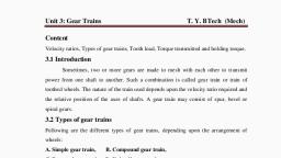
Unit 2: Toothed Gears, , T.Y. BTech (Mech), , spur gearing. These gears have teeth parallel to the axis of the wheel as shown in Fig., 2.1., , Fig 2.1 Spur gear, Advantage, , , Efficiency is more these gears (97-98%), , , , Cost is less, , , , Easy to manufacture, , Disadvantage, , , Noisy operation, , , , Not used for high speed operations, , Applications, , , Automobile gear boxes, watches etc., , B .Helical Gear, , Fig 2.2. (a) Helical Gear, Prof. Sachin M. Shinde, KECSP, , Page 2
Page 3 :
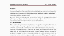
Unit 2: Toothed Gears, , T.Y. BTech (Mech), , Fig 2.2.(b) Helical Gear, Another name given to the spur gearing is helical gearing, in which the teeth are inclined, to the axis. The single and double helical gears connecting parallel shafts are shown in, Fig. 2.2 (a) and (b) respectively. The double helical gears are known as herringbone, gears., Advantage, , , Efficiency is high up to 98-98%, , , , Smooth in operation, , , , Stronger than spur gear, , Disadvantage, , , Cost is more, , , , Difficult to manufacture, , , , Wear and tear of those types of gear is high, , Applications, , , Automobile gear boxes, rolling mills, machine tool gear box sand high speed, applications etc., , C. Rack and pinion, , Fig 2.3 Rack and pinion, Prof. Sachin M. Shinde, KECSP, , Page 3
Page 4 :
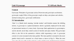
Unit 2: Toothed Gears, , T.Y. BTech (Mech), , These types of gear arrangement converts rotary motion of pinion into reciprocating, motion of rack, arrangement is as shown fig 2.3, Applications, , , Automobile steering gear box, lathe machine, milling, drilling machine etc., , D. Internal gear, In these types of gear, the teeth’s are inner surface which are may be spur or helical as, shown in figure 2.4, , Fig 2.4 Internal gear, Advantage, , , Space required is less, , , , Less friction between the teeth, , , , High efficiency, , Applications, , , Used in internal clutches and heavy duty vehicle., , E. Herringbone gears, The double helical gears are known as herringbone gears as shown in fig 2.5. A pair of, spur gears is kinematically equivalent to a pair of cylindrical discs, keyed to parallel, shafts and having a line contact., Advantage, , , Smooth and quite operation, , , , High load carrying capacity, , , , Reduces and thrust on bearing, , Prof. Sachin M. Shinde, KECSP, , Page 4
Page 5 :
Unit 2: Toothed Gears, , T.Y. BTech (Mech), , Disadvantage, , , Difficult to manufacture /machining, , , , Cost is more than and helical gear, , Fig 2.5 Herringbone gears, 2. Intersecting shaft axes gears, Bevel gears, Generally bevel gear are used when two shaft are at right angles to each other. Bevel, gears are available with straight .helical and spiral teeth as shown in fig 2.6 and 2.7, , Fig 2.6 straight bevel gear, Prof. Sachin M. Shinde, KECSP, , Page 5
Page 6 :
Unit 2: Toothed Gears, , T.Y. BTech (Mech), , Fig 2.7 spiral bevel gear, , Advantages, , , Noise is less, , , , Space required less as compared to helical ,spur gears, , , , Efficiency is high, , , , Can transmit motion between two intersecting shaft, , Disadvantage, , , Cost is more, , , , Difficult to manufacture, , Application, , , Differential gear boxes of automobiles, , 3. Non intersecting and perpendicular shaft axes gears, Worm gear, Worm and worm gears are used to transmit motion between two non-intersecting and, perpendicular shafts. The important property of gear is that it is non-reversible; it means, worm is always driver and worm gear is driven as shown in fig 2.8, , Prof. Sachin M. Shinde, KECSP, , Page 6
Page 7 :
Unit 2: Toothed Gears, , T.Y. BTech (Mech), , Fig 2.8 worm and worm gear, Advantages, , , Utilized for high reduction ratio, , , , Compact is size, , , , Smooth operation, , , , Self-locking gears, , Disadvantages, , , More expensive, , , , Efficiency is less, , , , More heat generated, , Application, , , Due to self-locking property, they are commonly used in steering mechanism,, hoisting devices, dam gates etc., , 4. Non intersecting and non-perpendicular shaft axes gear, Spiral gear, For transmitting motion between two Non intersecting and non-perpendicular shaft axes, spiral gear are used.it has line contact, the rotation of about which axes generates pitch, surfaces, called as hyperboloids., , Fig 2.9 spiral gear, Prof. Sachin M. Shinde, KECSP, , Page 7
Page 8 :
Unit 2: Toothed Gears, , T.Y. BTech (Mech), , 5. According to the peripheral velocity of the gears. The gears, according to the, peripheral velocity of the gears may be classified as :, (a) Low velocity, (b) Medium velocity, and (c) High velocity., The gears having velocity less than 3 m/s are termed as low velocity gears and gears, having velocity between 3 and 15 m/s are known as medium velocity gears. If the, velocity of gears is more than 15 m/s, then these are called high speed gears., , 2.3 Terminology of spur gears, The following terms, which will be mostly used in this chapter, should be clearly, understood at this stage. These terms are illustrated in Fig. 2.10., , Fig. 2.10. Terms used in gears., 1. Pitch circle. It is an imaginary circle which by pure rolling action, would give, the same motion as the actual gear., Prof. Sachin M. Shinde, KECSP, , Page 8
Page 9 :
Unit 2: Toothed Gears, , T.Y. BTech (Mech), , 2. Pitch circle diameter. It is the diameter of the pitch circle. The size of the gear, is usually specified by the pitch circle diameter. It is also known as pitch, diameter., 3. Pitch point. It is a common point of contact between two pitch circles., 4. Pitch surface. It is the surface of the rolling discs which the meshing gears have, replaced at the pitch circle., 5. Pressure angle or angle of obliquity. It is the angle between the common, normal to two gear teeth at the point of contact and the common tangent at the, pitch point. It is usually denoted by φ., The standard pressure angles are 14(1/2)0 , and 20°., 6. Addendum. It is the radial distance of a tooth from the pitch circle to the top of, the tooth., 7. Dedendum. It is the radial distance of a tooth from the pitch circle to the bottom, of the tooth., 8. Addendum circle. It is the circle drawn through the top of the teeth and is, concentric with the pitch circle., 9. Dedendum circle. It is the circle drawn through the bottom of the teeth. It is, also called root circle., Note: Root circle diameter = Pitch circle diameter × cos φ, where φ is the, pressure angle., 10. Circular pitch. It is the distance measured on the circumference of the pitch, circle from a point of one tooth to the corresponding point on the next tooth. It is, usually denoted by Pc, Mathematically,, Circular pitch,, Where D = Diameter of the pitch circle, and, T = Number of teeth on the wheel., A little consideration will show that the two gears will mesh together correctly, if, the two wheels have the same circular pitch., Note: If D1 and D2 are the diameters of the two meshing gears having the teeth, T1 and T2 respectively, then for them to mesh correctly,, , or, Prof. Sachin M. Shinde, KECSP, , Page 9
Page 10 :
Unit 2: Toothed Gears, , T.Y. BTech (Mech), , 11. Diametral pitch. It is the ratio of number of teeth to the pitch circle diameter in, millimeters. It is denoted by Pd. Mathematically,, Diametral pitch, Pd, , Where T = Number of teeth, and, D = Pitch circle diameter., 12. Module. It is the ratio of the pitch circle diameter in millimeters to the number, of teeth. It is usually denoted by m. Mathematically,, Module, m = D /T, Note: The recommended series of modules in Indian Standard are 1, 1.25, 1.5, 2,, 2.5, 3, 4, 5, 6, 8, 10, 12, 16, and 20. The modules 1.125, 1.375, 1.75, 2.25, 2.75,, 3.5, 4.5, 5.5, 7, 9, 11, 14 and 18 are of second choice., 13. Clearance. It is the radial distance from the top of the tooth to the bottom of the, tooth, in a meshing gear. A circle passing through the top of the meshing gear is, known as clearance circle., 14. Total depth. It is the radial distance between the addendum and the dedendum, circles of a gear. It is equal to the sum of the addendum and dedendum., 15. Working depth., , It is the radial distance from the addendum circle to the, , clearance circle. It is equal to the sum of the addendum of the two meshing gears., 16. Tooth thickness. It is the width of the tooth measured along the pitch circle., 17. Tooth space. It is the width of space between the two adjacent teeth measured, along the pitch circle., 18. Backlash. It is the difference between the tooth space and the tooth thickness, as, measured along the pitch circle. Theoretically, the backlash should be zero, but, in actual practice some backlash must be allowed to prevent jamming of the teeth, due to tooth errors and thermal expansion., 19. Face of tooth. It is the surface of the gear tooth above the pitch surface., 20. Flank of tooth. It is the surface of the gear tooth below the pitch surface., 21. Top land. It is the surface of the top of the tooth., 22. Face width. It is the width of the gear tooth measured parallel to its axis., 23. Profile. It is the curve formed by the face and flank of the tooth., 24. Fillet radius. It is the radius that connects the root circle to the profile of the, tooth., Prof. Sachin M. Shinde, KECSP, , Page 10
Page 11 :
Unit 2: Toothed Gears, , T.Y. BTech (Mech), , 25. Path of contact. It is the path traced by the point of contact of two teeth from, the beginning to the end of engagement., 26. *Length of the path of contact. It is the length of the common normal cut-off, by the addendum circles of the wheel and pinion., 27. ** Arc of contact. It is the path traced by a point on the pitch circle from the, beginning to the end of engagement of a given pair of teeth. The arc of contact, consists of two parts, i.e., (a) Arc of approach. It is the portion of the path of contact from the beginning, of the engagement to the pitch point., (b) Arc of recess. It is the portion of the path of contact from the pitch point to, the end of the engagement of a pair of teeth., Note: The ratio of the length of arc of contact to the circular pitch is known as, contact ratio i.e. number of pairs of teeth in contact., , 2.4 Gear Materials, The material used for the manufacture of gears depends upon the strength and service, conditions like wear, noise etc. The gears may be manufactured from metallic or nonmetallic materials. The metallic gears with cut teeth are commercially obtainable in cast, iron, steel and bronze. The nonmetallic materials like wood, raw hide, compressed paper, and synthetic resins like nylon are used for gears, especially for reducing noise., The cast iron is widely used for the manufacture of gears due to its good wearing, properties, excellent machinability and ease of producing complicated shapes by casting, method. The cast iron gears with cut teeth may be employed, where smooth action is not, important. The steel is used for high strength gears and steel may be plain carbon steel or, alloy steel. The steel gears are usually heat treated in order to combine properly the, toughness and tooth hardness. The phosphor bronze is widely used for worm gears in, order to reduce wear of the worms which will be excessive with cast iron or steel, , 2.5 Law of Gearing, Consider the portions of the two teeth, one on the wheel 1 (or pinion) and the other on, the wheel 2, as shown by thick line curves in Fig. 2.11. Let the two teeth come in contact, at point Q, and the wheels rotate in the directions as shown in the figure. Let TT be the, common tangent and MN be the common normal to the curves at the point of contact Q., From the centers O1 and O2, draw O1M and O2N perpendicular to MN. A little, consideration will show that the point Q moves in the direction, when considered as a, Prof. Sachin M. Shinde, KECSP, , Page 11
Page 12 :
Unit 2: Toothed Gears, , T.Y. BTech (Mech), , point on wheel 1, and in the direction when considered as a point on wheel 2. Let v1 and, v2 be the velocities of the point Q on the wheels1 and 2 respectively. If the teeth are to, remain in contact, then the components of these velocities along the common normal, MN must be equal., , Fig 2.11 law of gearing, , ∴ v1, , = v2, , Also from similar triangles O1MP and O2NP, , Combining equations (i) and (ii), we have, , Combining equations (i) and (ii), we have, , Prof. Sachin M. Shinde, KECSP, , Page 12
Page 13 :
Unit 2: Toothed Gears, , T.Y. BTech (Mech), , From above, we see that the angular velocity ratio is inversely proportional to the ratio, of the distances of the point P from the centers O1 and O2, or the common normal to the, two surfaces at the point of contact Q intersects the line of centers at point P which, divides the centre distance inversely as the ratio of angular velocities., Therefore in order to have a constant angular velocity ratio for all positions of the, wheels, the point P must be the fixed point (called pitch point) for the two wheels. In, other words, the common normal at the point of contact between a pair of teeth must, always pass through the pitch point. This is the fundamental condition which must be, satisfied while designing the profiles for the teeth of gear wheels. It is also known as law, of gearing., Notes:, 1. The above condition is fulfilled by teeth of involute form, provided that the root, circles from which the profiles are generated are tangential to the common normal., 2. If the shape of one tooth profile is arbitrarily chosen and another tooth is designed to, satisfy the above condition, then the second tooth is said to be conjugate to the first. The, conjugate teeth are not in common use because of difficulty in manufacture, and cost of, production., 3. If D1 and D2 are pitch circle diameters of wheels 1 and 2 having teeth T 1 and T2, respectively, then velocity ratio,, , Velocity of Sliding of Teeth, The sliding between a pair of teeth in contact at Q occurs along the common tangent T T, to the tooth curves as shown in Fig. 2.11. The velocity of sliding is the velocity of one, tooth relative to its mating tooth along the common tangent at the point of contact., The velocity of point Q, considered as a point on wheel 1, along the common tangent TT, is represented by EC. From similar triangles QEC and O1MQ,, , Similarly, the velocity of point Q, considered as a point on wheel 2, along the common, tangent TT is represented by ED. From similar triangles QCD and O2NQ,, , Prof. Sachin M. Shinde, KECSP, , Page 13
Page 14 :
Unit 2: Toothed Gears, , T.Y. BTech (Mech), , 2.6 Conjugate tooth action, We have seen that one essential for correctly meshing gears is that the size of the teeth, (the module) must be the same for the two gears. We now examine another requirement, - the shape of teeth necessary for the speed ratio to remain constant during an increment, of rotation; this behaviour of the contacting surfaces (ie. the teeth flanks) is known, as conjugate action., , Fig 2.11, Consider the two rigid bodies 1 and 2 which rotate about fixed centers, O, with angular, velocities ω. The bodies touch at the contact point, C, through which the common, tangent and normal are drawn. The absolute velocity v of the contact point reckoned as a, point on either body, is perpendicular to the radius from that body's centre O to the, contact point. For the bodies to remain in contact, there must be no component of, relative motion along the common normal, so that from the velocity triangles: v2 cosθ2 = v1 cosθ1, Where v1 = ω1 . O1C;, , v2 = ω2 . O2C, , Note that the tangential components of velocity are generally different, so sliding must, occur. For the speed ratio to be constant therefore, from the above and similar triangles:, ω2 /ω1 = v2 . O1C/v1 . O2C = O1C.cosθ1 /O2C.cosθ2= O1 C1 /O2 C2 = O1 P / O2 P, ie. this ratio also must be constant. This indicates that, since the centers are fixed, the, point P is fixed too. In general therefore, whatever the shapes of the bodies, the contact, Prof. Sachin M. Shinde, KECSP, , Page 14
Page 15 :
Unit 2: Toothed Gears, , T.Y. BTech (Mech), , point C will move along some locus as rotation proceeds; but if the action is to be, conjugate then the body geometry must be such that the common normal at the contact, point passes always through one unique point lying on the line of centers - this point is, the pitch point referred to above, and the pitch circles' radii are O 1 P and O2 P., There exists a host of shapes which ensure conjugacy - indeed it is possible, within, certain restrictions, to arbitrarily choose the shape of one body then determine the shape, of the second necessary for conjugacy. But by far the most common gear geometry, which satisfies conjugacy is based on the involute, in which case both gears are similar, in form, and the contact point's locus is a simple straight line - the line of action., , 2.7 Involute and cycloidal profiles, A) Involute profile, An involute of a circle is a plane curve generated by a point on a tangent, which rolls on, the circle without slipping or by a point on a taut string which in unwrapped from a reel, as shown in Fig. 2.12., , Fig. 2.12 Involute profile, In connection with toothed wheels, the circle is known as base circle. The, involute is traced as follows: Let A be the starting point of the involute. The base circle, is divided into equal number of parts e.g. AP 1, P1P2, and P2P3 etc. The tangents at P1, P2,, P3 etc. are drawn and the length P1A1, P2A2, P3A3 equal to the arcs AP1, AP2 and AP3 are, set off. Joining the points A, A1, A2, A3 etc. we obtain the involute, curve AR. A little consideration will show that at any instant A3, the tangent A3T to the, involute is perpendicular to P3A3 and P3 A3 is the normal to the involute. In other words,, normal at any point of an involute is a tangent to the circle, Prof. Sachin M. Shinde, KECSP, , Page 15
Page 16 :
Unit 2: Toothed Gears, , T.Y. BTech (Mech), , B) Cycloidal profiles, A cycloid is the curve traced by a point on the circumference of a circle which rolls, without slipping on a fixed straight line., , Fig. 2.13 cycloid, When a circle rolls without slipping on the outside of a fixed circle, the curve traced by a, point on the circumference of a circle is known as epicycloid., , Fig. 2.13 Epicycloid and hypocycloid, On the other hand, if a circle rolls without slipping on the inside of a fixed circle, then, the curve traced by a point on the circumference of a circle is called hypo-cycloid., Prof. Sachin M. Shinde, KECSP, , Page 16
Page 17 :
Unit 2: Toothed Gears, , T.Y. BTech (Mech), , Difference between Involute and cycloidal profiles, Sr no, 1, , Involute profiles, Pressure angle remains same, throughout the operation., , 2, 3, , Teeth’s are weaker., It is easier to manufacture due to, convex surface., , 4, , The velocity is not affected due to, variation in centre distance., Interference takes place., More wear and tear as contact takes, place between convex surfaces., , 5, 6, , Cycloidal profiles, Pressure angle keeps on changing during, the operation. The angle is maximum at, the start and end of engagement. It is zero, at pitch point., Teeth’s are stronger., It is difficult to manufacture due to, requirement of hypocycloid and, epicycloids., The centre distance should remain the, same., There is no interference., Less wear and tear as concave flank, makes contact with convex flank., , 2.8 Length of Path of Contact, Consider a pinion driving the wheel as shown in Fig. 2.14. When the pinion rotates in, clockwise direction, the contact between a pair of involute teeth begins at K (on the, flank near the base circle of pinion or the outer end of the tooth face on the wheel) and*, ends at L (outer end of the tooth face on the pinion or on the flank near the base circle of, wheel). MN is the common normal at the point of contacts and the common tangent to, the base circles. The point K is the intersection of the addendum circle of wheel and the, common tangent. The point L is the intersection of the addendum circle of pinion and, common tangent., , Fig. 2.14. Length of path of contact, Prof. Sachin M. Shinde, KECSP, , Page 17
Page 18 :
Unit 2: Toothed Gears, , T.Y. BTech (Mech), , We have discussed in Art. 2.4 That the length of path of contact is the length of common, normal cut-off by the addendum circles of the wheel and the pinion. Thus the length of, path of contact is KL which is the sum of the parts of the path of contacts KP and PL., The part of the path of contact KP is known as path of approach and the part of the path, of contact PL is known as path of recess., Let rA = O1L = Radius of addendum circle of pinion,, RA = O2K = Radius of addendum circle of wheel,, r = O1P = Radius of pitch circle of pinion, and, R = O2P = Radius of pitch circle of wheel., From Fig. 2.14, we find that radius of the base circle of pinion,, O1M = O1P cos φ = r cos φ, and radius of the base circle of wheel,, O2N = O2P cos φ = R cos φ, Now from right angled triangle O2KN,, , 2.9 Length of Arc of Contact, We have already defined that the arc of contact is the path traced by a point on the pitch, circle from the beginning to the end of engagement of a given pair of teeth. In Fig. 2.14,, the arc of contact is EPF or GPH. Considering the arc of contact GPH, it is divided into, two parts i.e. arc GP and arc. The arc GP is known as arc of approach and the arc PH is, called arc of recess. The angles subtended by these arcs at O are called angle of, approach and angle of recess respectively., Prof. Sachin M. Shinde, KECSP, , Page 18
Page 19 :
Unit 2: Toothed Gears, , T.Y. BTech (Mech), , We know that the length of the arc of approach (arc GP), , =, , =, and the length of the arc of recess (arc PH), , =, , =, , Since the length of the arc of contact GPH is equal to the sum of the length of arc of, approach and arc of recess, therefore,, Length of the arc of contact, = arc GP + arc PH =, , +, , =, , =, 2.10 Contact Ratio (or Number of Pairs of Teeth in Contact), The contact ratio or the number of pairs of teeth in contact is defined as the ratio of the, length of the arc of contact to the circular pitch. Mathematically, Contact ratio or, number of pairs of teeth in contact, , =, where Circular pitch, and Pc =π m and m = Module., Notes: 1. The contact ratio, usually, is not a whole number. For example, if the contact, ratio is 1.6, it does not mean that there are 1.6 pairs of teeth in contact. It means that, there are alternately one pair and two pairs of teeth in contact and on a time basis the, average is 1.6., 2. The theoretical minimum value for the contact ratio is one, that is there must always, be at least one pair of teeth in contact for continuous action., 3. Larger the contact ratio, more quietly the gears will operate., , 2.11 Interference in Involute Gears, Fig. 2.15 shows a pinion with centre O1, in mesh with wheel or gear with centre O2. MN, is the common tangent to the base circles and KL is the path of contact between the two, mating teeth., A little consideration will show that if the radius of the addendum circle of, pinion is increased to O1N, the point of contact L will move from L to N. When this, radius is further increased, the point of contact L will be on the inside of base circle of, wheel and not on the involute profile of tooth on wheel. The tip of tooth on the pinion, Prof. Sachin M. Shinde, KECSP, , Page 19
Page 20 :
Unit 2: Toothed Gears, , T.Y. BTech (Mech), , will then undercut the tooth on the wheel at the root and remove part of the involute, profile of tooth on the wheel. This effect is known as interference, and occurs when the, teeth are being cut., , Fig. 2.15. Interference in involute gears., In brief, the phenomenon when the tip of tooth undercuts the root on its mating gear is, known as interference. Similarly, if the radiuses of the addendum circle of the wheel, increases beyond O2M, then the tip of tooth on wheel will cause interference with the, tooth on pinion. The points M and N are called interference points. Obviously,, interference may be avoided if the path of contact does not extend beyond interference, points. The limiting value of the radius of the addendum circle of the pinion is*O 1N and, of the wheel is O2M.From the above discussion, we conclude that the interference may, only be avoided, if the point of contact between the two teeth is always on the involute, profiles of both the teeth. In other words, interference may only be prevented, if the, addendum circles of the two mating gears cut the common tangent to the base circles, between the points of tangency., When interference is just avoided, the maximum length of path of contact is MN when, the maximum addendum circles for pinion and wheel pass through the points of, tangency N and M respectively as shown in Fig. 2.15. In such a case,, Maximum length of path of approach,, MP = r sin φ, and maximum length of path of recess,, Prof. Sachin M. Shinde, KECSP, , Page 20
Page 21 :
Unit 2: Toothed Gears, , T.Y. BTech (Mech), PN = R sin φ, , ∴ Maximum length of path of contact,, MN = MP + PN = r sin φ + R sin φ = (r + R) sin φ, and maximum length of arc of contact, , Note: In case the addenda on pinion and wheel is such that the path of approach and path, of recess are half of their maximum possible values, then, , Path of approach, KP = (1/2) MP, , and path of recess, PL= (1/2) PN, , ∴ Length of the path of contact, , 2.11 .1 Minimum number of teeth on the pinion in order to avoid interference, We have already discussed in the previous article that in order to avoid interference, the, addendum circles for the two mating gears must cut the common tangent to the base, circles between the points of tangency. The limiting condition reaches, when the, addendum circles of pinion and wheel pass through points N and M (see Fig. 2.15), respectively., Let t = Number of teeth on the pinion,, T = Number of teeth on the wheel,, m = Module of the teeth,, r = Pitch circle radius of pinion = m.t / 2, G = Gear ratio = T / t = R / r, φ = Pressure angle or angle of obliquity., From triangle O1NP,, , Prof. Sachin M. Shinde, KECSP, , Page 21
Page 22 :
Unit 2: Toothed Gears, , T.Y. BTech (Mech), , ∴ Limiting radius of the pinion addendum circle,, , Let AP.m = Addendum of the pinion, where AP is a fraction by which the standard, addendum of one module for the pinion should be multiplied in order to avoid, interference., We know that the addendum of the pinion, = O1N – O1P, , This equation gives the minimum number of teeth required on the pinion in order to, avoid interference., Notes : 1. If the pinion and wheel have equal teeth, then G = 1. Therefore the above, equation reduces to, , 2.11.2 Minimum number of teeth on the wheel in order to avoid interference, Let , T = Minimum number of teeth required on the wheel in order to avoid interference,, and AW. m = Addendum of the wheel, where AW is a fraction by which the standard, Prof. Sachin M. Shinde, KECSP, , Page 22
Page 23 :
Unit 2: Toothed Gears, , T.Y. BTech (Mech), , Addendum for the wheel should be multiplied., Using the same notations as in Art. 2.11,1 We have from triangle O2MP, , ∴ Limiting radius of wheel addendum circle,, , We know that the addendum of the wheel, , Prof. Sachin M. Shinde, KECSP, , Page 23
Page 24 :
Unit 2: Toothed Gears, , T.Y. BTech (Mech), , 2.11.3 Minimum number of teeth on a pinion for involute rack in order to avoid, interference, A rack and pinion in mesh is shown in Fig. 2.16., Let t = Minimum number of teeth on the pinion,, r = Pitch circle radius of the pinion = m.t / 2, and, φ = Pressure angle or angle of obliquity, and, AR.m = Addendum for rack, where AR is the fraction by which the standard addendum, of one module for the rack is to be multiplied., , Fig. 2.16. Rack and pinion in mesh, We know that a rack is a part of toothed wheel of infinite diameter. Therefore its base, circle diameter and the profiles of the involute teeth are straight lines. Since these, straight profiles are tangential to the pinion profiles at the point of contact, therefore they, are perpendicular to the tangent PM. The point M is the interference point., Addendum for rack,, , 2.12 Undercutting, Fig 2.17 shows, base circle of pinion is more than the addendum circle of gear. The part, of tooth below the base circle is not involute and it will interface tip of the tooth on, mating pinion which is an involute .if pinion is cut by standard tool like gear hob which, also interface with portion of the tooth below the base circle and will cut away the, Prof. Sachin M. Shinde, KECSP, , Page 24
Page 25 :
Unit 2: Toothed Gears, , T.Y. BTech (Mech), , interfacing material, then this processes is called as undercutting. Due to pinion will, weak and fail early., , Fig 2.17, , 2.13 Rack shift, The involute tooth profile will get affected when number of teeth is below minimum., The shape look like a shape scooped by cutter tool. The distorted involute curve or the, scooped out shape condition from base circle is called undercut. The strength of gear, reduces and it has bad influence to gear contact due shortened involute curve., The calculation formula for minimum number of teeth to prevent under cut is as follows, , Where, Ø is cutter pressure angle, The undercut is generally appears when number of teeth is less than 17 or pressure angle, is less than 200. According to DIN standards, minimum number of teeth is 14accepting, slight undercut which may cause no serious influence, , Fig 2.18, Prof. Sachin M. Shinde, KECSP, , Page 25
Page 26 :
Unit 2: Toothed Gears, , T.Y. BTech (Mech), , Profile shifted gear, Usually a rack tool (like hob tool) for fabricating profile shifted gear has following, advantage, , , Adjust tooth thickness for gear pair to achieve equal gear strength, , , , Prevent undercut for gear with less than minimum number of teeth., , , , For deviated center distance, fabricate a modified gear to correct the fault center, distance, , , , Less gear noise level with suitable contact ratio., , , , The wear of flank to adjust specific sliding, , Positive profile shifts (+): reference pitch line of rack type cutter shifts x-times of, module towards outer radius direction, Negative profile shifts (-): reference pitch line of rack type cutter shifts x-times of, module towards inner radius direction, x.m is commonly called the amount of rack shift where x is called rack shift, coefficient, , Fig 2.19 rack shift for spur gear, Rack shift coefficient to prevent undercut, The undercut is generally appears when number of teeth is less than 17 or pressure, angle is less than 200. The undercut can be prevented using theoretical rack shift, coefficient by following calculation formula, X= 17- (t /17), Where, t = practical number of teeth, Prof. Sachin M. Shinde, KECSP, , Page 26
Page 27 :
Unit 2: Toothed Gears, , T.Y. BTech (Mech), , Theoretical rack shift coefficient for spur gear with number of teeth 10 with pressure, angle 200 is given by following formula, X = 17 – 10/17, = 0.412, , Fig 2.20 spur gear with full depth (rack shift coefficient x = 0), , Fig 2.24 positive (+) profile shifted gear (rack shift coefficient x = 0.25), Rack shift coefficient to adjust Centre distance, Below is the explanation using examples. For example, calculate Rack shift, coefficient for adjustable gear with Centre distance of 80.5mm (Proper distance is, 80.0mm) with:, Gear: Spur gear,, Pressure angle:20°,, Prof. Sachin M. Shinde, KECSP, , Page 27
Page 28 :
Unit 2: Toothed Gears, , T.Y. BTech (Mech), , Module: 2.0mm,, Number of teeth for Pinion: 20,, Number of teeth for Gear: 60,, Centre distance modification coefficient, y = (a'−a) / m = (80.5 − 80) / 2 = 0.25, , a’ : Actual centre distance (mm), a : Proper centre distance (mm), z1 : Number of teeth for Pinion, z2 : Number of teeth for Gear, α0 : Pressure angle of Cutter (°), αw: pressure angle (°), y : Centre distance increment coefficient, x1 : Rack shift coefficient for Pinion, x2 : Rack shift coefficient for Gear, invα0 : Functional involute for Cutter pressure angle, invα0 = tanα0 −α0 inv20° = 0.0149044, (The lastα0 is in Radian Unit), One may provide the sum (0.2557) of this Rack shift coefficient to Pinion only or, can divide between Gear and Pinion., Prof. Sachin M. Shinde, KECSP, , Page 28
Page 29 :
Unit 2: Toothed Gears, , T.Y. BTech (Mech), , 2.14 Effect of center distance variations, Now, let O1 and O2 be the fixed centre of the two base circles as shown in Fig. 2.25 (a)., Let the corresponding involutes AB and A1B1 are in contact at point Q. MQ and NQ are, normal to the involutes at Q and are tangents to base circles. Since the normal of an, involute at a given point is the tangent drawn from that point to the base circle, therefore, the common normal MN at Q is also the common tangent to the two base circles. We see, that the common normal MN intersects the line of centre O1O2 at the fixed point P, (called pitch point). Therefore the involute teeth satisfy the fundamental condition of, constant velocity ratio., , Fig. 2.25. Involute teeth, From similar triangles O2NP and O1MP,, , This determines the ratio of the radii of the two base circles. The radii of the base circles, is given by, , Also the centre distance between the base circles,, , Prof. Sachin M. Shinde, KECSP, , Page 29
Page 30 :
Unit 2: Toothed Gears, , T.Y. BTech (Mech), , where φ is the pressure angle or the angle of obliquity. It is the angle which the common, normal to the base circles (i.e. MN) makes with the common tangent to the pitch circles., When the power is being transmitted, the maximum tooth pressure (neglecting friction at, the teeth) is exerted along the common normal through the pitch point. This force may, be resolved into tangential and radial or normal components. These components act, along and at right angles to the common tangent to the pitch circles., If F is the maximum tooth pressure as shown in Fig. 2.25 (b), then Tangential force,, FT = F cos φ, and radial or normal force, FR = F sin φ., ∴, , Torque exerted on the gear shaft = FT × r, where r is the pitch circle radius of the, , gear., Note: The tangential force provides the driving torque and the radial or normal force, produces radial deflection of the rim and bending of the shafts., we have seen that the velocity ratio for the involute teeth gears is given by, , Let, in Fig. 2.19 (a), the centre of rotation of one of the gears (say wheel 1) is shifted, from O1 to O1’. Consequently the contact point shifts from Q to Q '.The common normal, to the teeth at the point of contact Q ' is the tangent to the base circle, because it has a, contact between two involute curves and they are generated from the base circle. Let the, tangent M' N’ to the base circles intersects O1′O2 at the pitch point P’. As a result of this,, the wheel continues to work* correctly., Now from similar triangles O2NP and O1MP,, , and from similar triangles O2N'P' and O1'M'P',, , But O2N = O2N', and O1 M = O1'M'. Therefore, from equations (ii) and (iii),, , Thus, we see that if the centre distance is changed within limits, the velocity ratio, remains unchanged. However, the pressure angle increases (from φ to φ′) with the, increase in the centre distance., Prof. Sachin M. Shinde, KECSP, , Page 30
Page 31 :
Unit 2: Toothed Gears, , T.Y. BTech (Mech), , 2.15 Friction between gear teeth, The motion and power transmitted by gears is kinematically equivalent to that, transmitted by friction wheels or discs. In order to understand how the motion can be, transmitted by two toothed wheels, consider two plain circular wheels A and B mounted, on shafts, having sufficient rough surfaces and pressing against each other as shown in, Fig. 2.26 (a). Let the wheel A be keyed to the rotating shaft and the wheel B to the shaft,, to be rotated. A little consideration will show that when the wheel A is rotated by a, rotating shaft, it will rotate the wheel B in the opposite direction as shown in Fig. 2.26, (a). The wheel B will be rotated (by the wheel A) so long as the tangential force exerted, by the wheel A does not exceed the maximum frictional resistance between the two, wheels. But when the tangential force (P) exceeds the *frictional resistance (F), slipping, will take place between the two wheels. Thus, the friction drive is not a positive drive., , Fig 2.26, In order to avoid the slipping, a number of projections (called teeth) as shown in Fig., 2.26 (b), are provided on the periphery of the wheel A, which will fit into the, corresponding recesses on the periphery of the wheel B. A friction wheel with the teeth, cut on it is known as toothed wheel or gear. The usual connection to show the toothed, wheels is by their **pitch circles. Note: Kinematically, the friction wheels running, without slip and toothed gearing are identical. But due to the possibility of slipping of, wheels, the friction wheels can only be used for transmission of small powers., The frictional force F is equal to µ. RN, where µ = Coefficient of friction between the, rubbing surface of two wheels, and RN = Normal reaction between the two rubbing, surfaces., Prof. Sachin M. Shinde, KECSP, , Page 31
Page 32 :
Unit 2: Toothed Gears, , T.Y. BTech (Mech), , 2.16 Helical gears, There is a basic difference between spur and helical gears. While the teeth of spur gears, are cut parallel to the axis of the shaft, the teeth of helical gears are cut in the form of a, helix on the pitch cylinder. In spur gears, the contact between meshing teeth occurs, along the entire face width of the tooth, resulting in sudden application of the load,, which in turn, results in impact conditions and generates noise in high speed, applications. In helical gears, the contact between meshing teeth begins with a point on, the leading edge of the tooth and gradually extends along the diagonal line across the, tooth. There is a gradual pick-up of load by the tooth, resulting in smooth engagement, and quiet operation even at high speeds. Helical gears are used in automobiles, turbines, and high-speed applications even up to 3000 m/min. There are two basic types of helical, gears, parallel and crossed. Parallel helical gears operate on two parallel shafts. In this, case, the magnitude of the helix angle is the same for the pinion and the gear, however,, the hand of the helix is opposite. A right-hand pinion meshes with a left-hand gear and, vice versa. Crossed helical gears are mounted on shafts with crossed axes. Their teeth, may have the same or opposite hand of the helix. The discussion in this chapter is, mainly limited to the design of parallel helical gears, , 2.17 Terminology of helical gear, , Fig. 2.27 Tooth Relationships, Prof. Sachin M. Shinde, KECSP, , Page 32
Page 33 :
Unit 2: Toothed Gears, , T.Y. BTech (Mech), , 1. Helix angle (ψ): It is defined as the angle between the axis of the shaft and the centre, line of the tooth taken on the pitch plane. The angle A1B2 A2 is the helix angle ψ, 2. Transverse circular pitch (pt): The distance between corresponding points on, adjacent teeth measured along pitch circle in transverse plane is called the transverse, circular pitch (p), The distance A1 A2 is called the transverse circular pitch (pt), 3. Normal circular pitch (pn): The distance between corresponding points on adjacent, teeth measured along pitch circle in normal plane is called the normal circular pitch (pn), From fig 2.27, =, Or, We know that, circular pitch = π x module, Above equation can rewritten as, π mn = π mt, mn = mt, =, Where, mn = normal module, mt = transverse module, 4. Transverse pressure angle (αt): transverse pressure angle measured along in, transverse plane is called as transverse pressure angle., 5. Normal pressure angle (αn): normal pressure angle measured along in normal plane, is called as normal pressure angle, =, 6. Pitch circle diameter (d): The normal pressure angle is usually 20°. The pitch circle, diameter d of the helical gear is given by,, , 7. The centre to centre distance (a): The centre to centre distance a between the two, helical gears having zl and z2 as the number of teeth is given by,, , Prof. Sachin M. Shinde, KECSP, , Page 33
Page 34 :
Unit 2: Toothed Gears, , T.Y. BTech (Mech), , The speed ratio i for helical gears is determined in the same manner as for the spur, gears, i.e.,, , where suffix p and g refer to the pinion and gear respectively., , 2.18 Virtual number of teeth, The pitch cylinder of the helical gear is cut by the plane A–A, which is normal to the, tooth elements as shown in Fig. 2.28. The intersection of the plane A–A and the pitch, cylinder (extended) produces an ellipse. This ellipse is shown by a dotted line. The semimajor and semi-minor axes of this ellipse are (, , ) and ( ) respectively. It can be, , proved from analytical geometry that the radius of curvature r’ at the point B is given by,, …………………………...i, where a and b are semi-major and semi-minor axes respectively. Substituting the values, of a and b in the expression for r’,, , r’=, , ………………………………ii, , Fig. 2.28 Formative Gear, Prof. Sachin M. Shinde, KECSP, , Page 34
Page 35 :
Unit 2: Toothed Gears, , T.Y. BTech (Mech), , In the design of helical gears, an imaginary spur gear is considered in the plane A–A, with centre at Ol having a pitch circle radius of rl and module mn. It is called a, ‘formative’ or ‘virtual’ spur gear. The pitch circle diameter d1 of the virtual gear is given, by,, dl = 2 r’=, , Put, , ……………………………. iii, , in following equation, , We get, , where z is the actual number of teeth, , 2.19 Force analysis and torque transmitted by helical gears, The resultant force P acting on the tooth of a helical gear is resolved into three, components, Pt, Pr and Pa as shown in Fig. 2.29 (a), where, Pt = tangential component (N), Pr = radial component (N), Pa = axial or thrust component (N), The normal pressure angle αn is in the plane ABC shaded by dots, while helix angle ψ is, in the lower plane BCD., From the triangle ABC,, , From the triangle BDC,, , From Eqs (c) and (d),, Pa = Pt tan ψ……………………………………… (i), From Eqs (a) and (d),, Pr = Pt *, , +.................................................................... (ii), , Prof. Sachin M. Shinde, KECSP, , Page 35
Page 36 :
Unit 2: Toothed Gears, , T.Y. BTech (Mech), , Fig. 2.29 Components of Tooth Force, The tangential component is calculated from the relationship, Pt =, , ………………………………………………………...(iii), , Where, Mt = transmitted torque (N-mm), d = pitch circle diameter (mm), In examples of gear tooth forces, it is often required to find out the magnitude and, direction of the three components. The magnitudes are determined by using the, following four equations,, Mt = (, , Pr = Pt *, , ), , +, , Pa = Pt tan ψ, Where the suffix p is used for pinion, Prof. Sachin M. Shinde, KECSP, , Page 36
Page 37 :
Unit 2: Toothed Gears, , T.Y. BTech (Mech), , The following information is required in order to decide the direction of the three, components:, (i) Which is the driving element? Which is the driven element?, (ii) Is the pinion rotating in clockwise or anticlockwise direction?, (iii) What is the hand of the helix? Is it right-handed or left-handed?, The directions of tangential and radial components are decided by the same method that, is used for spur gears., (i) Tangential Component (Pt), (a) The direction of tangential component for a driving gear is opposite to the direction, of rotation., (b) The direction of tangential component for a driven gear is same as the direction of, rotation., (ii) Radial Component (Pr), (a) The radial component on the pinion acts towards the centre of the pinion., (b) The radial component on the gear acts towards the centre of the gear., (iii) Thrust Component (Pa), The following guidelines can be used to determine the direction of the thrust component:, (a) Select the driving gear from the pair., (b) Use right hand for RH-helix and left hand for LH-helix., (c) Keep the fingers in the direction of rotation of the gear and the thumb will indicate, the direction of the thrust component for the driving gear., (d) The direction of the thrust component for the driven gear will be opposite to that for, the driving gear, , 2.20 Spiral Gears, We have already discussed that spiral gears (also known as skew gears or screw gears), are used to connect and transmit motion between two non-parallel and non-intersecting, shafts. The pitch surfaces of the spiral gears are cylindrical and the teeth have point, contact. These gears are only suitable for transmitting small power. We have seen that, helical gears, connected on parallel shafts, are of opposite hand. But spiral gears may be, of the same hand or of opposite hand., 2.20.1 Centre Distance for a Pair of Spiral Gears, The centre distance, for a pair of spiral gears, is the shortest distance between the two, shafts making any angle between them. A pair of spiral gears 1 and 2, both having left, Prof. Sachin M. Shinde, KECSP, , Page 37
Page 38 :
Unit 2: Toothed Gears, , T.Y. BTech (Mech), , hand helixes (i.e. the gears are of the same hand) is shown in Fig. 2.30. The shaft angle θ, is the angle through which one of the shafts must be rotated so that it is parallel to the, other shaft, also the two shafts be rotating in opposite directions., , Fig 2.30 Centre distance for a pair of spiral gears., Let α1 and α2 = Spiral angles of gear teeth for gears 1 and 2, , respectively,, , pc1 and pc2 = Circular pitches of gears 1 and 2,, T1 and T2 = Number of teeth on gears1 and 2,, d1 and d2= Pitch circle diameters of gears 1 and 2,, N1 and N2 = Speed of gears 1 and 2,, G = Gear ratio =, , =, , pN = Normal pitch, and, L = Least centre distance between the axes of shaft, , Prof. Sachin M. Shinde, KECSP, , Page 38
Page 39 :
Unit 2: Toothed Gears, , T.Y. BTech (Mech), , Notes: 1. if the pair of spiral gears have teeth of the same hand, then, θ = α1 + α2, and for a pair of spiral gears of opposite hand,, θ = α1 – α2, 2. When θ = 90°, then both the spiral gears must have teeth of the same hand., , 2.21 Efficiency of Spiral Gears, A pair of spiral gears 1 and 2 in mesh is shown in Fig. 2.31. Let the gear 1 be the driver, and the gear 2 the driven. The forces acting on each of a pair of teeth in contact are, shown in Fig. 2.31. The forces are assumed to act at the centre of the width of each teeth, and in the plane tangential to the pitch cylinders., , Fig 2.31 Efficiency of spiral gears., Let F1 = Force applied tangentially on the driver,, F2 = Resisting force acting tangentially on the driven,, Prof. Sachin M. Shinde, KECSP, , Page 39
Page 42 :
Unit 2: Toothed Gears, , T.Y. BTech (Mech), , From fig 2.32, Component of VA along tooth profile = VA, Component of VB along tooth profile = VB, Velocity of sliding between spiral gear A and B is, VS= VA, VS =, , + VB, +, , 2.23 Worm gears, Worm gear drives are used to transmit power between two non-intersecting shafts,, which are, in general, at right angles to each other. The worm gear drive consists of a, worm and a worm wheel. The worm is a threaded screw, while the worm wheel is a, toothed gear. The teeth on the worm wheel envelope the threads on the worm and give, line contact between mating parts., , Fig 2.33 worm and worm wheel, Advantages, The advantages of worm gear drives are as follows:, (i) The most important characteristic of worm gear drives is their high-speed reduction., A speed reduction as high as 100: 1 can be obtained with a single pair of worm gears., (ii) The worm gear drives are compact with small overall dimensions, compared with, equivalent spur or helical gear drives having same speed reduction., (iii) The operation is smooth and silent., (iv) Provision can be made for self-locking operation, where the motion is transmitted, only from the worm to the worm wheel. This is advantageous in applications like, cranes and lifting devices, Disadvantage, The disadvantage of the worm gear drives are as follows:, (i) The efficiency is low compared with other types of gear drives., (ii) The worm wheel, in general, is made of phosphor bronze, which increases the cost., Prof. Sachin M. Shinde, KECSP, , Page 42
Page 43 :
Unit 2: Toothed Gears, , T.Y. BTech (Mech), , (iii) Considerable amount of heat is generated in worm gear drives, which is required to, be dissipated by lubricating oil to the housing walls and finally to the surroundings., (iv) The power transmitting capacity is low. Worm gear drives are used for up to 100, kW of power transmission, , 2.24 Terminologies of worm gears, , Fig 2.34 Worm Gear Terminology, A pair of worm gears is specified and designated by four quantities in the following, manner: z1/z2/q/m, Where,, z1 = number of starts on the worm, z2 = number of teeth on the worm wheel, q = diametral quotient, m = module (mm), The diametral quotient is given by,, …………………………………………(i), Prof. Sachin M. Shinde, KECSP, , Page 43
Page 44 :
Unit 2: Toothed Gears, , T.Y. BTech (Mech), , where d1 is the pitch circle diameter of the worm A schematic diagram of the worm and, worm wheel is shown in Fig. 2.34(a). d1 and d2 are pitch circle diameters of the worm, and the worm wheel respectively. The worm is similar to a screw with single-start or, multi-start threads. The threads of the worm have an involute helicoid profile. The, following terms are used in terminology of worm gear drives:, (i) Axial Pitch: The axial pitch (px) of the worm is defined as the distance measured, from a point on one thread to the corresponding point on the adjacent thread, measured, along the axis of the worm., (ii) Lead: The lead (l) of the worm is defined as the distance that a point on the helical, profile will move when the worm is rotated through one revolution. It is the thread, advance in one turn. For single-start threads, the lead is equal to the axial pitch. For, double start threads, the lead is twice the axial pitch, and so on. Therefore,, l = px z1…………………………………. (ii), The pitch circle diameter of the worm wheel is given by, d2 = mz…………………………………. (iii), As seen in the figure 2.34, the axial pitch of the worm should be equal to the circular, pitch of the worm wheel. Therefore,, , px = πm …………………………………. (iv), From Eqs (ii) and (iv),, l = πmz1 …………………………………. (v), When one thread of the worm is developed, it becomes the hypotenuse of a triangle as, shown in Fig. 2.34(b). The base of this triangle is equal to the lead of the worm, while, the altitude is equal to the circumference of the worm. There are two angles related to, this triangle, namely, lead angle and helix angle., (iii) Lead Angle: The lead angle (γ) is defined as the angle between a tangent to the, thread at the pitch diameter and a plane normal to the worm axis. From the triangle in, Fig. 2.34(b),, …………………………………. (vi), From Eqs (i) and (v),, , Prof. Sachin M. Shinde, KECSP, , Page 44
Page 45 :
Unit 2: Toothed Gears, , T.Y. BTech (Mech), , …………………………. (vi), (iv) Helix Angle: The helix angle (ψ) is defined as the angle between a tangent to the, thread at the pitch diameter and the axis of the worm. The worm helix angle is the, complement of the worm lead angle., , (v) Pressure Angle: The tooth pressure angle (α) is measured in a plane containing the, axis of the worm and it is equal to one-half of the thread angle. It is illustrated in Fig., 2.33(c). The pressure angle should not be less than 20° for single and double start, worms and 25° for triple and multi-start worms., (vi) Centre distance: From Fig. 2.34(a), the centre distance is given by, , 2.25 Force Analysis of worm gear, The analysis of three components of the resultant tooth force between the meshing teeth, of worm and worm wheel is based on the following assumptions:, (i) The worm is the driving element, while the worm wheel is the driven element., (ii) The worm has right-handed threads., (iii) The worm rotates in anti-clockwise directions as shown in Fig. 2.35., , Fig 2.35 Components of Tooth Force, Prof. Sachin M. Shinde, KECSP, , Page 45
Page 46 :
Unit 2: Toothed Gears, , T.Y. BTech (Mech), , The three components of the gear tooth force between the worm and the worm wheel are, shown in Fig. 2.35. Suffix 1 is used for the worm, while suffix 2 for the worm wheel., The components of the resultant force acting on the worm are as follows:, (P1)t = tangential component on the worm (N), (P1)a = axial component on the worm (N), (P1)r = radial component on the worm (N), The components (P2)t, (P2)a and (P2)r acting on the worm wheel are defined in a similar, way. The force acting on the worm wheel is the equal and opposite reaction of the force, acting on the worm., Therefore,, (P2)t = (P1)a …………………………..(i), (P2)a = (P1)t ………………..………. (ii), (P2)r = (P1)r………………………….. (iii), In the present analysis, the expressions are derived for the components of force acting on, the worm. The components of force acting on the worm wheel can be determined by the, above relationship. It is difficult to understand the directions of components with the, help of two views shown in Fig. 20.4. It is better to construct an isometric sketch of the, worm and worm wheel for understanding the directions. The directions can be decided, with the help of such isometric sketches illustrated in Fig. 2.36., , Fig 2.36 Direction of Force Components, Prof. Sachin M. Shinde, KECSP, , Page 46
Page 47 :
Unit 2: Toothed Gears, , T.Y. BTech (Mech), , (i) Tangential Component (P1)t The worm is the driving element. It is rotating in an, anti-clockwise direction, when viewed from A. For the driving element, the direction of, tangential component is opposite to the direction of rotation. Therefore, (P1)t will act in, the positive X direction at the point of contact., (ii) Axial Component (P1)a The worm has right-hand threads and when the right-hand, thumb rule is applied, by keeping the fingers in the direction of rotation, the thumb will, be projecting along the positive Y-axis. Therefore, if we treat the worm as ‘screw’ and, the worm wheel as ‘nut’, the screw will have a tendency to move in the direction of the, thumb or along the positive Y-axis. The nut or the worm wheel will have a tendency to, move in the opposite direction, i.e., along the negative Y-axis. Therefore, the worm, wheel will rotate in the anti-clockwise direction when observed from the bearing B. The, worm wheel is the driven member and the direction of (P 2)t will be the same as the, direction of rotation or along the negative Y-axis. Since, (P1)a and (P2)t are equal and, opposite, the axial component (P1)a will act in the positive Y direction at the point of, contact., (iii) Radial Component (P1)r The radial component always acts towards the centre of, gear. Therefore, (P1)r will act towards the centre of the worm or along the negative Zdirection at the point of contact., The resultant force acting on the worm consists of two components—components of, normal reaction between the meshing teeth and components of frictional force. The two, components are superimposed to get the resultant components. The components of the, normal reaction P acting on the worm are shown in Fig. 2.37. Here, α is the normal, pressure angle, while γ is the lead angle. Note that the angle α is in the plane ABCD, shaded by dots, while the angle γ is in the top plane AEBF. Resolving the normal, reaction P in the plane ABCD shown in Fig. 2.37(b), , Resolving the component PN in the plane AEBF shown in Fig. 2.37 (c),, , From relationships (a), (b), (c) and (d),, , …………………………………………...(i), Prof. Sachin M. Shinde, KECSP, , Page 47
Page 48 :
Unit 2: Toothed Gears, , T.Y. BTech (Mech), , Fig 2.37 Components of normal reaction, The frictional force is significant in worm gear drives, because there is sliding motion, between the threads of the worm and the teeth of the worm wheel, as compared with the, rolling motion between the teeth of the pinion and gear in other types of gears. The, resultant frictional force is (μP) where m is the coefficient of friction. The direction of, the frictional force will be along the pitch helix and opposite to the direction of rotation,, as shown in Fig. 2.38. There are two components of the frictional force:, , Fig. 2.38 Components of Frictional Force, Prof. Sachin M. Shinde, KECSP, , Page 48
Page 49 :
Unit 2: Toothed Gears, , T.Y. BTech (Mech), , (i) Component (μP cos γ) in the tangential direction. The direction of this component is, same as that of Pt., (ii) Component (μPsinγ) in the axial direction. The direction of this component is, opposite to that of Pa., Superimposing the components of normal reaction and frictional force, we have, , ……………………………………(ii), , ………………………………………(iii), ………………………………. (iv), In practice, the tangential component (P1)t on the worm is determined from the torque, that is transmitted from the worm to the worm wheel., ……………………………...(v), From Eqs (ii) and (iii),, , …………………………. (vi), From Eqs (ii) and (iv),, ……………………………...(vii), , 2.26 The efficiency of the worm gear, The efficiency of the worm gear drive is given by,, , From equation iv, Prof. Sachin M. Shinde, KECSP, , Page 49
Page 50 :
Unit 2: Toothed Gears, , T.Y. BTech (Mech), , From equation v, , The efficiency of spur or helical gears is very high and virtually constant in the range of, 98% to 99%. On the other hand, the efficiency of worm gears is low and varies, considerably in the range of 50% to 98%. In general, the efficiency is inversely, proportional to speed ratio, provided the coefficient of friction is constant. In general, the, worm is the driver and the worm wheel is the driven member and the reverse motion, is not possible. This is called ‘self-locking’ drive, because the worm wheel cannot drive, the worm. As for screw threads, the criterion for self-locking is the relationship between, the coefficient of friction and lead angle. A worm gear drive is said to be self-locking if, the coefficient of friction is greater than tangent of lead angle, i.e., the friction angle is, more than the lead angle. This approximate condition is rewritten as,, μ > tan γ, There is another term, ‘reversible’ or ‘overrunning’ or ‘back-driving’ worm gear drive., In this type of drive, the worm and worm wheel can drive each other. In general, the, worm is the driver and the worm wheel is the driven member. If the driven machinery, has large inertia and if the driving power supply is cut off suddenly, the worm is freely, driven by the worm wheel. This prevents the damage to the drive and source of power., A worm-gear drive is said to be reversible if the coefficient of friction is less than, tangent of lead angle, i.e., the friction angle is less than the lead angle. This approximate, condition is rewritten as,, μ < tan γ, , 2.27 Bevel gear, Bevel gears are gears where the axes of the two shafts intersect and the tooth-bearing, faces of the gears themselves are conically shaped. Bevel gears are most often mounted, on shafts that are 90 degrees apart, but can be designed to work at other angles as well., Prof. Sachin M. Shinde, KECSP, , Page 50
Page 51 :
Unit 2: Toothed Gears, , T.Y. BTech (Mech), , Types of bevel gear, , , Straight bevel gears have conical pitch surface and teeth are straight and tapering, towards apex., , , , Spiral bevel gears have curved teeth at an angle allowing tooth contact to be, gradual and smooth., , Advantages, , , Quiet Operating noise (Quiet operation is particularly advantageous in, environments such as theatres or airports.), , , , Increased torque capacity compared to worm gears of the same size., , , , High efficiency (rolling of bevel gears is very efficient compared to the sliding, effect of worm gears (98.5%). The metal bevel gear teeth never come into direct, contact with an oil film.), , , , Hollow shaft possible, , Disadvantages, , , High costs., , , , Bevel gears are manufactured in pairs. For maintenance and repair, both gears, must be replaced., , , , In order to achieve high efficiency, bevel gear sets must be positioned exactly, so, the shafts must be adjusted very precisely., , , , Limited translation range. Maximum ratio of 6:1 per bevel gear set. Spur gear, stages are necessary in order to achieve a higher overall gear ratio., , , , Bevel gears are not recommended for high-speed reduction. At high speed, a, bevel gear unit generates noise., , 2.28 Terminology of bevel gears, A bevel gear is in the form of the frustum of a cone. The dimensions of a bevel gear are, illustrated in Fig.2.39(a) and (b). The following terms are important in terminology of, bevel gears:, (i) Pitch Cone Pitch cone is an imaginary cone, the surface of which contains the pitch, lines of all teeth in the bevel gear., (ii) Cone Centre The apex of the pitch cone is called the cone centre. It is denoted by O., (iii) Cone Distance Cone distance is the length of the pitch-cone element. It is also, called pitch-cone radius. It is denoted by A0., , Prof. Sachin M. Shinde, KECSP, , Page 51
Page 52 :
Unit 2: Toothed Gears, , T.Y. BTech (Mech), , (iv) Pitch Angle The angle that the pitch line makes with the axis of the gear, is called, the pitch angle. It is denoted by γ. The pitch angle is also called centre angle., (v) Addendum Angle It is the angle subtended by the addendum at the cone centre. It is, denoted by α., (vi) Dedendum Angle It is the angle subtended by the dedendum at the cone centre. It is, denoted by δ., , Fig 2.39 Terminology of Bevel Gear, (vii) Face Angle It is the angle subtended by the face of the tooth at the cone centre., Face angle = pitch angle + addendum angle = γ + α., (viii) Root Angle It is the angle subtended by the root of the tooth at the cone centre., Root angle = pitch angle – dedendum angle = γ – δ., (ix) Back Cone The back cone is an imaginary cone and its elements are perpendicular, to the elements of the pitch cone., (x) Back Cone Distance It is the length of the back-cone element. It is also called back, cone radius. It is denoted by rb, A pair of bevel gears is shown in Fig. 2.40. Dp and Dg are the pitch circle diameters of, pinion and gear respectively. γ is the pitch angle of the pinion, while β is the pitch, angle of the gear. Line AB is perpendicular to the line OB. Consider the triangle OAB,, , Prof. Sachin M. Shinde, KECSP, , Page 52
Page 53 :
Unit 2: Toothed Gears, , T.Y. BTech (Mech), , Therefore, , Similarly, it can be proved that, , Also, , Fig 2.40 Pair of bevel gears, The cone distance A0 is given by, , 2.29 Tooth forces and geometric relationship, In force analysis, it is assumed that the resultant tooth force between two meshing teeth, of a pair of bevel gears is concentrated at the midpoint along the face width of the tooth., This is illustrated in Fig. 2.41 (a), where the resultant force P, shown by the dotted line,, , Prof. Sachin M. Shinde, KECSP, , Page 53
Page 54 :
Unit 2: Toothed Gears, , T.Y. BTech (Mech), , acts at the midpoint D of the face width of the pinion. The resultant force has following, three components:, Pt = tangential or useful component (N), Pr = radial component (N), Pa = axial or thrust component (N), Consider the plane ABCD shaded by dots in Fig. 2.41 (a) and again shown in Fig. 2.41, (b). From the triangle BCD,, , where,, Ps = separating component (N), α = pressure angle (degrees), From (a),, , Refer to, , Fig 2.41 Components of Tooth Face, , Prof. Sachin M. Shinde, KECSP, , Page 54
Page 55 :
Unit 2: Toothed Gears, , T.Y. BTech (Mech), , Fig. 2.41(a). The separating force Ps is perpendicular to the pitch line OD. Therefore,, AD perpendicular to OD and Line FD is vertical, while the line OX is horizontal., Therefore, FD perpendicular OX, There are two pairs of perpendicular lines and their, included angle should be equal. The angle between lines OD and OX should be equal to, the angle between the lines AD and FD. The angle between lines OD and OX is the, pitch angle γ. Therefore, the angle between lines AD and FD should, , Substituting Eq. (b) in the above expressions,, ………………………………………. (i), …………………………………………. (ii), The tangential component is determined from the following relationship:, , …………………………………………………………(iii), where,, Mt = torque transmitted by gears (N-mm), rm = radius of the pinion at midpoint along the face width (mm), Equations (i), (ii) and (iii) are used to determine the components of the tooth force on the, pinion. The components of the tooth force acting on the gear can be determined by, considering actions and reactions as equal and opposite. A two- dimensional, representation of force components is illustrated in Fig. 2.42. As shown in Fig. 2.42(b),, the mean radius (rm) where the resultant force acts, is given by,, , …………………………………………...(iv), where b = face width of the tooth (mm) .As seen in Fig.2.42 (c), the radial component on, the gear is equal to the axial component (Pa) on the pinion. Similarly, the axial, component on the gear is equal to the radia1 component (P r) on the pinion, Prof. Sachin M. Shinde, KECSP, , Page 55
Page 56 :
Unit 2: Toothed Gears, , T.Y. BTech (Mech), , Fig 2.42 Force Analysis, . In two-dimensional representation of forces, very often (•) and (x) are used to indicate, forces perpendicular to the plane of the paper. (•) Indicates a force that is perpendicular, to the plane of paper and which is towards the observer. (x), Indicates a force that is perpendicular to the plane of the paper and which is away from, the observer. In examples of bevel gear tooth forces, it is often required to fi nd out the, magnitude and direction of three components acting on the pinion and gear., Force Components on Pinion, The magnitudes are determined by using the following five equations:, , Note that the notations (Pt), (Pr) and (Pa) are used for components of force on pinion, only. The directions of tangential and radial components acting on the pinion and gear, are decided by same method that is used for spur gears., Prof. Sachin M. Shinde, KECSP, , Page 56
Page 57 :
Unit 2: Toothed Gears, , T.Y. BTech (Mech), , (i) Tangential Component (Pt), (a) The direction of tangential component for the driving gear is opposite to the, direction of rotation., (b) The direction of tangential component for the driven gear is same as the direction of, rotation., (ii) Radial Component (Pr), (a) The radial component on the pinion acts towards the centre of the pinion., (b) The radial component on the gear acts towards the centre of the gear., (iii) Thrust Component (Pa), The following guidelines can be used to determine the direction of the thrust component:, (a) The thrust component on the pinion is equal and opposite of the radial component on, the gear., (b) The thrust component on the gear is equal and opposite of the radial component on, the pinion., , 2.30 Force Analysis of spur gear, , Fig 2.43 Spur gear tooth force, In gears, power is transmitted by means of a force exerted by the tooth of the, driving gear on the meshing tooth of the driven gear. Figure 2.43 shows the tooth of the, driving pinion exerting a force PN on the tooth of the driven gear. According to the, fundamental law of gearing, this resultant force P N always acts along the pressure line., The resultant force PN can be resolved into two components—tangential component Pt, Prof. Sachin M. Shinde, KECSP, , Page 57
Page 58 :
Unit 2: Toothed Gears, , T.Y. BTech (Mech), , and radial component Pr at the pitch point as shown in Figure 2.44. The tangential, component Pt is a useful load because it determines the magnitude of the torque and, consequently the power, which is transmitted. The radial component Pr is a separating, force, which is always directed towards the centre of the gear., , Fig. 2.44 Components of Tooth Force, The torque transmitted by the gears is given by,, , Where,, Mt = torque transmitted by gears (N-mm), KW = power transmitted by gears (kW), n = speed of rotation (rpm), The tangential component Pt acts at the pitch circle radius. Therefore,, , From Fig. 2.44, , Prof. Sachin M. Shinde, KECSP, , Page 58
Page 59 :
Unit 2: Toothed Gears, , T.Y. BTech (Mech), , The resultant force PN is given by, , The above analysis of the gear tooth force is based on the following assumptions:, (i) As the point of contact moves, the magnitude of the resultant forces PN changes., This effect is neglected in the above analysis., (ii) It is assumed that only one pair of teeth takes the entire load. At times there are two, pairs, which are simultaneously in contact and share the load. This aspect is, neglected in the analysis., (iii) The analysis is valid under static conditions, i.e., when the gears are running at very, low velocities. In practice, there is dynamic force in addition to force due to power, transmission. The effect of this dynamic force is neglected in the analysis., , Prof. Sachin M. Shinde, KECSP, , Page 59
 Learn better on this topic