Notes of BTech-V, TOM-II Unit 1 Belt & Rope Drive - Study Material
Page 1 :
Unit 1: Belt and Rope Drives, , T. Y. BTech (Mech), , Content, Flat belts, Effect of slip, Centrifugal tension, Creep, Crowing of pulley, and Initial, tension in belts. V- Belts, Virtual coefficient of friction, Effect of V-groove on torque, transmitted. Rope drives, Rope constructions, Advantages of rope drives., , 1. Introduction, The belts or ropes are used to transmit power from one shaft to another by means of, pulleys which rotate at the same speed or at different speeds. The amount of power, trans-mitted depends upon the following factors:, 1. The velocity of the belt., 2. The tension under which the belt is placed on the pulleys., 3. The arc of contact between the belt and the smaller pulley., 4. The conditions under which the belt is used., It may be noted that, (a) The shafts should be properly in line to insure uniform tension across the belt, section., (b) The pulleys should not be too close together, in order that the arc of contact on the, smaller pulley may be as large as possible., (c) The pulleys should not be so far apart as to cause the belt to weigh heavily on the, shafts, thus in-creasing the friction load on the bearings, (d) A long belt tends to swing from side to side, causing the belt to run out of the, pulleys, which in turn develops crooked spots in the belt., (e) The tight side of the belt should be at the bottom, so that whatever sag is present on, the loose side will increase the arc of contact at the pulleys., (f) In order to obtain good results with flat belts, the maximum distance between the, shafts should not exceed 10 meters and the minimum should not be less than 3.5 times, the diameter of the larger pulley., 1.1. Selection of a Belt Drive, Following are the various important factors upon which the selection of a belt drive, depends:, 1. Speed of the driving and driven shafts, 2. Speed reduction ratio,, 3. Power to be transmitted, 4. Centre distance between the shafts,, 5. Positive drive requirements, 6. Shafts layout,, 7. Space available, and 8. Service conditions., , Prof. Sachin M. Shinde,KECSP, , Page 1
Page 2 :
Unit 1: Belt and Rope Drives, , T. Y. BTech (Mech), , 1.2 Types of Belt Drives, The belt drives are usually classified into the following three groups :, 1. Light drives. These are used to transmit small powers at belt speeds up to about 10, m/s, as in agricultural machines and small machine tools., 2. Medium drives. These are used to transmit medium power at belt speeds over 10 m/s, but up to 22 m/s, as in machine tools., 3. Heavy drives. These are used to transmit large powers at belt speeds above 22 m/s,, as in compressors and generators., 1.3 Types of Belts, , (a) Flat belt. (b) V-belt. (c) Circular belt., Fig. 1.1. Types of belts., Though there are many types of belts used these days, yet the following are important, from the subject point of view:, 1. Flat belt. The flat belt, as shown in Fig. 1.1 (a), is mostly used in the factories and, workshops, where a moderate amount of power is to be transmitted, from one pulley to, another when the two pulleys are not more than 8 meters apart., 2. V-belt. The V-belt, as shown in Fig. 1.1 (b), is mostly used in the factories and work, shops, where a moderate amount of power is to be transmitted, from one pulley to, another, when the two pulleys are very near to each other., 3. Circular belt or rope. The circular belt or rope, as shown in Fig. 1.1 (c), is mostly, used in the factories and workshops, where a great amount of power is to be transmitted,, from one pulley to another, when the two pulleys are more than 8 meters apart., If a huge amount of power is to be transmitted, then a single belt may not be sufficient., In such a case, wide pulleys (for V-belts or circular belts) with a number of grooves are, used. Then a belt in each groove is provided to transmit the required amount of power, from one pulley to another., 1.4. Material used for Belts: The material used for belts and ropes must be strong,, flexible, and durable. It must have a high coefficient of friction. The belts, according to, the material used, are classified as follows:, , Prof. Sachin M. Shinde,KECSP, , Page 2
Page 3 :
Unit 1: Belt and Rope Drives, , T. Y. BTech (Mech), , 1. Leather belts. The most important material for the belt is leather. The best leather, belts are made from 1.2 meters to 1.5 meters long strips cut from either side of the back, bone of the top grade steer hides. The hair side of the leather is smoother and harder than, the flesh side, but the flesh side is stronger. The fibres on the hair side are perpendicular, to the surface, while those on the flesh side are interwoven and parallel to the surface., Therefore for these reasons, the hair side of a belt should be in contact with the pulley, surface, as shown in Fig. 1.2. This gives a more intimate contact between the belt and, the pulley and places the greatest tensile strength of the belt section on the outside,, where then tension is maximum as the belt passes over the pulley., , (a) Single layer belt. (b) Double layer belt., Fig. 1.2. Leather belts., The leather may be either oak-tanned or mineral salt tanned e.g. chrome tanned. In order, to increase the thickness of belt, the strips are cemented together. The belts are specified, according to the number of layers e.g. single, double or triple ply and according to the, thickness of hides used e.g. light, medium or heavy. The leather belts must be, periodically cleaned and dressed or treated with a compound or dressing containing, neat’s foot or other suitable oils so that the belt will remain soft and flexible., 2. Cotton or fabric belts. Most of the fabric belts are made by folding canvass or, cotton duck to three or more layers (depending upon the thickness desired) and stitching, together. These belts are woven also into a strip of the desired width and thickness. They, are impregnated with some filler like linseed oil in order to make the belts water proof, and to prevent injury to the fibers. The cotton belts are cheaper and suitable in warm, climates, in damp atmospheres and in exposed positions. Since the cotton belts require, little attention, therefore these belts are mostly used in farm machinery, belt conveyor, etc., 3. Rubber belt. The rubber belts are made of layers of fabric impregnated with rubber, composition and have a thin layer of rubber on the faces. These belts are very flexible, but are quickly destroyed if allowed to come into contact with heat, oil or grease. One of, , Prof. Sachin M. Shinde,KECSP, , Page 3
Page 4 :
Unit 1: Belt and Rope Drives, , T. Y. BTech (Mech), , the principal advantages of these belts is that they may be easily made endless. These, belts are found suitable for saw mills, paper mills where they are exposed to moisture., 4. Balata belts. These belts are similar to rubber belts except that balata gum is used in, place of rubber. These belts are acid proof and water proof and it is not affected by, animal oils or alkalis. The balata belts should not be at temperatures above 40° C, because at this temperature the balata begins to soften and becomes sticky. The strength, of balata belts is 25 per cent higher than rubber belts., 1.5. Types of Flat Belt Drives, The power from one pulley to another may be transmitted by any of the following types, of belt drives:, 1. Open belt drive. The open belt drive, as shown in Fig. 1.3, is used with shafts, arranged parallel and rotating in the same direction. In this case, the driver A pulls the, belt from one side (i.e. Lower side RQ) and delivers it to the other side (i.e. upper side, LM). Thus the tension in the lower side belt will be more than that in the upper side belt., The lower side belt (because of more tension) is known as tight side whereas the upper, side belt (because of less tension) is known as slack side, as shown in Fig. 1.3, , Fig. 1.3. Open belt drive., 2. Crossed or twist belt drive. The crossed or twist belt drive, as shown in Fig. 1.4, is, used with shafts arranged parallel and rotating in the opposite directions., , Fig. 1.4. Crossed or twist belt drive., , Prof. Sachin M. Shinde,KECSP, , Page 4
Page 5 :
Unit 1: Belt and Rope Drives, , T. Y. BTech (Mech), , In this case, the driver pulls the belt from one side (i.e. RQ) and delivers it to the other, side (i.e. LM). Thus the tension in the belt RQ will be more than that in the belt LM. The, belt RQ (because of more tension) is known as tight side, whereas the belt LM (because, of less tension) is known as slack side, as shown in Fig. 1.4., A little consideration will show that at a point where the belt crosses, it rubs against each, other and there will be excessive wear and tear. In order to avoid this, the shafts should, be placed at a maximum distance of 20 b, where b is the width of belt and the speed of, the belt should be less than 15 m/s., 3. Quarter turn belt drive. The quarter turn belt drive also known as right angle belt, drive, as shown in Fig. 11.5 (a), is used with shafts arranged at right angles and rotating, in one definite direction. In order to prevent the belt from leaving the pulley, the width, of the face of the pulley should be greater or equal to 1.4 b, where b is the width of belt., In case the pulleys cannot be arranged, as shown in Fig. 1.5 (a), or when the reversible, motion is desired, then a quarter turn belt drive with guide pulley, as shown in Fig. 1.5, (b), may be used., , (a) Quarter turn belt drive., , (b) Quarter turn belt drive with guide pulley., , Fig. 1.5 Quarter turn belt drive, 4. Belt drive with idler pulleys. A belt drive with an idler pulley, as shown in Fig. 1.6, (a), is used with shafts arranged parallel and when an open belt drive cannot be used due, to small angle of contact on the smaller pulley. This type of drive is provided to obtain, high velocity ratio and when the required belt tension cannot be obtained by other, means., , Prof. Sachin M. Shinde,KECSP, , Page 5
Page 6 :
Unit 1: Belt and Rope Drives, , T. Y. BTech (Mech), , (a) Belt drive with single idler pulley. (b) Belt drive with many idler pulleys., Fig. 1.6, When it is desired to transmit motion from one shaft to several shafts, all arranged in, parallel, a belt drive with many idler pulleys, as shown in Fig. 1.6 (b), may be employed., 5. Compound belt drive. A compound belt drive, as shown in Fig. 1.7, is used when, power is transmitted from one shaft to another through a number of pulleys., , Fig. 1.7. Compound belt drive., 6. Stepped or cone pulley drive. A stepped or cone pulley drive, as shown in Fig. 1.8,, is used for changing the speed of the driven shaft while the main or driving shaft runs at, constant speed. This is accomplished by shifting the belt from one part of the steps to the, other., 7. Fast and loose pulley drive. A fast and loose pulley drive, as shown in Fig. 1.9, is, used when the driven or machine shaft is to be started or stopped whenever desired, without interfering with the driving shaft. A pulley which is keyed to the machine shaft, is called fast pulley and runs at the same speed as that of machine shaft. A loose pulley, runs freely over the machine shaft and is incapable of transmitting any power. When the, , Prof. Sachin M. Shinde,KECSP, , Page 6
Page 7 :
Unit 1: Belt and Rope Drives, , T. Y. BTech (Mech), , driven shaft is required to be stopped, the belt is pushed on to the loose pulley by means, of sliding bar having belt forks., , Fig. 1.8. Stepped or cone pulley drive, , Fig. 1.9. Fast and loose pulley drive., , 1.7. Velocity Ratio of Belt Drive, It is the ratio between the velocities of the driver and the follower or driven. It may be, expressed, mathematically, as discussed below:, Let d1 = Diameter of the driver,, d2 = Diameter of the follower,, N1= Speed of the driver in r.p.m., and, N2 = Speed of the follower in r.p.m., ∴ Length of the belt that passes over the driver, in one minute = π d1.N1, Similarly, length of the belt that passes over the follower, in one minute= π d2. N2, Since the length of belt that passes over the driver in one minute is equal to the length of, belt that passes over the follower in one minute, therefore, π d1.N1= π d2. N2, Velocity ratio,, When the thickness of the belt (t) is considered, then velocity ratio,, , 1.8 Velocity Ratio of a Compound Belt, Sometimes the power is transmitted from one shaft to another, through a number of, pulleys as shown in Fig. 1.7. Consider a pulley 1 driving the pulley 2. Since the pulleys, 2 and 3 are keyed to the same shaft, therefore the pulley 1 also drives the pulley 3 which,, in turn, drives the pulley 4., , Prof. Sachin M. Shinde,KECSP, , Page 7
Page 8 :
Unit 1: Belt and Rope Drives, , T. Y. BTech (Mech), , Let d1 = Diameter of the pulley 1,, N1 = Speed of the pulley 1 in r.p.m.,, d2 , d3 , d4 , and N2 , N3 , N4 = Corresponding values for pulleys 2, 3 and 4., We know that velocity ratio of pulleys 1 and 2,, , Similarly, velocity ratio of pulleys 3 and 4,, , Multiplying equations (i) and (ii),, , A little consideration will show, that if there are six pulleys, then, , =, , 1.9 Slip of Belt, In the previous articles, we have discussed the motion of belts and shafts assuming a, firm frictional grip between the belts and the shafts. But sometimes, the frictional grip, becomes insufficient. This may cause some forward motion of the driver without, carrying the belt with it. This may also cause some forward motion of the belt without, carrying the driven pulley with it. This is called slip of the belt and is generally, expressed as a percentage. The result of the belt slipping is to reduce the velocity ratio of, the system. As the slipping of the belt is a common phenomenon, thus the belt should, never be used where a definite velocity ratio is of importance (as in the case of hour,, minute and second arms in a watch)., Let s1 % = Slip between the driver and the belt, and, s2 % = Slip between the belt and the follower., ∴ Velocity of the belt passing over the driver per second, , Prof. Sachin M. Shinde,KECSP, , Page 8
Page 9 :
Unit 1: Belt and Rope Drives, v=, , -, , x, , =, , (, , T. Y. BTech (Mech), )……………………………….(i), , and velocity of the belt passing over the follower per second,, , Substituting the value of v from equation (i),, , If thickness of the belt (t) is considered, then, , =, , (, , ), , Example 1.1. An engine, running at 150 r.p.m., drives a line shaft by means of a belt., The engine pulley is 750 mm diameter and the pulley on the line shaft being 450 mm. A, 900 mm diameter pulley on the line shaft drives a 150 mm diameter pulley keyed to a, dynamo shaft. Find the speed of the dynamo shaft, when 1. there is no slip, and 2. there, is a slip of 2% at each drive., Solution: Given: N1 = 150 r.p.m. ; d1 = 750 mm ; d2 = 450 mm ; d3 = 900 mm ; d4 = 150, mm. The arrangement of belt drive is shown in Fig. 1.10., , Figure 1.10, , Prof. Sachin M. Shinde,KECSP, , Page 9
Page 10 :
Unit 1: Belt and Rope Drives, , T. Y. BTech (Mech), , Let N4 = Speed of the dynamo shaft, 1. When there is no slip, We know that, , 2. When there is a slip of 2% at each drive, We know that, , 1.10. Creep of Belt, When the belt passes from the slack side to the tight side, a certain portion of the belt, extends and it contracts again when the belt passes from the tight side to slack side. Due, to these changes of length, there is a relative motion between the belt and the pulley, surfaces. This relative motion is termed as creep. The total effect of creep is to reduce, slightly the speed of the driven pulley or follower. Considering creep, the velocity ratio, is given by, , =, , X, , √, √, , Where, σ1 and σ2 = Stress in the belt on the tight and slack side respectively, and, E = Young’s modulus for the material of the belt., , Example 1.2. The power is transmitted from a pulley 1 m diameter running at 200 r.p.m., to a pulley 2.25 m diameter by means of a belt. Find the speed lost by the driven pulley, as a result of creep, if the stress on the tight and slack side of the belt is 1.4 MPa and 0.5, MPa respectively. The Young’s modulus for the material of the belt is 100 MPa., Solution. Given: d1 = 1 m ; N1 = 200 r.p.m. ; d2 = 2.25 m ; σ1 = 1.4 MPa = 1.4 × 10⁶ N/, m2; σ2 = 0.5 MPa = 0.5 × 10⁶ N/m2 ; E = 100 MPa = 100 × 106 N/ m2, Let N2 = Speed of the driven pulley., , Prof. Sachin M. Shinde,KECSP, , Page 10
Page 11 :
Unit 1: Belt and Rope Drives, , T. Y. BTech (Mech), , Neglecting creep, we know that, , Considering creep, we know that, , ∴ Speed lost by driven pulley due to creep = 88.9 – 88.7 = 0.2 r.p.m. Ans., , 1.11. Length of Open Belt Drive, , Fig. 1.11. Length of an open belt drive., We have already discussed in Art. 1.6 that in an open belt drive, both the pulleys rotate, in the same direction as shown in Fig. 1.11., Let r1 and r2 = Radii of the larger and smaller pulleys,, x = Distance between the centers of two pulleys (i.e. O1 O2), and, L = Total length of the belt., Let the belt leaves the larger pulley at E and G and the smaller pulley at F and H as, shown in Fig. 1.11. Through O2, draw O2M parallel to FE., From the geometry of the figure, we find that O2M will be perpendicular to O1E., Let the angle MO2O1 = α radians., We know that the length of the belt,, L =Arc GJE + EF + Arc FKH + HG, = 2 (Arc JE + EF + Arc FK) ...................................................................................... (i), From the geometry of the figure, we find that, , Prof. Sachin M. Shinde,KECSP, , Page 11
Page 12 :
Unit 1: Belt and Rope Drives, , T. Y. BTech (Mech), , Since α is very small, therefore putting, , sin α = α (in radians) = (, ∴ Arc JE = r1 (, , )…………………………………………...(ii), , )…………………………………………………. (iii), , Similarly,, , Expanding this equation by binomial theorem,, , Substituting the values of arc JE from equation (iii), arc FK from equation (iv) and EF, from equation (v) in equation (i), we get, , Substituting the value of, , Prof. Sachin M. Shinde,KECSP, , Page 12
Page 13 :
Unit 1: Belt and Rope Drives, , T. Y. BTech (Mech), , 1.12. Length of a Cross Belt Drive, We have already discussed in Art. 1.6 that in a cross belt drive, both the pulleys rotate in, opposite directions as shown in Fig. 1.12., , Fig. 1.12: Length of a cross belt drive., Let r1 and r2 = Radii of the larger and smaller pulleys,, x = Distance between the centers of two pulleys (i.e. O1O2), and, L = Total length of the belt., Let the belt leaves the larger pulley at E and G and the smaller pulley at F and H, as, shown in Fig. 1.12. Through O2, draw O2M parallel to FE., From the geometry of the figure, we find that O2M will be perpendicular to O1E., Let the angle MO2 O1 = α radians., We know that the length of the belt,, L =Arc GJE + EF + Arc FKH + HG, = 2 (Arc JE + EF + Arc FK) ......................................................................................(i), From the geometry of the figure, we find that, , Prof. Sachin M. Shinde,KECSP, , Page 13
Page 14 :
Unit 1: Belt and Rope Drives, , T. Y. BTech (Mech), , Since α is very small, therefore putting, , Expanding this equation by binomial theorem,, , Substituting the values of arc JE from equation (iii), arc FK from equation (iv) and EF, from equation (v) in equation (i), we get, , Prof. Sachin M. Shinde,KECSP, , Page 14
Page 15 :
Unit 1: Belt and Rope Drives, , T. Y. BTech (Mech), , It may be noted that the above expression is a function of (r1 + r2). It is thus obvious that, if sum of the radii of the two pulleys be constant, then length of the belt required will, also remain constant, provided the distance between centers of the pulleys remain, unchanged., , 1.13. Power Transmitted by a Belt, Fig. 1.14 shows the driving pulley (or driver) A and the driven pulley (or follower) B., We have already discussed that the driving pulley pulls the belt from one side and, delivers the same to the other side. It is thus obvious that the tension on the former side, (i.e. tight side) will be greater than the latter side (i.e. slack side) as shown in Fig. 1.14., Let T1 and T2 = Tensions in the tight and slack side of the belt respectively in newton’s,, r1 and r2 = Radii of the driver and follower respectively, and, v = Velocity of the belt in m/s, , Fig. 1.14 Power transmitted by a belt., The effective turning (driving) force at the circumference of the follower is the, difference between the two tensions (i.e. T1 – T2)., ∴ Work done per second = (T1 – T2) v N-m/s, and power transmitted,, , P = (T1 – T2) v, , W ...(∵ 1 N-m/s = 1 W), , A little consideration will show that the torque exerted on the driving pulley is (T1 – T2), r1.Similarly, the torque exerted on the driven pulley i.e. follower is (T1 – T2) r2., , Prof. Sachin M. Shinde,KECSP, , Page 15
Page 16 :
Unit 1: Belt and Rope Drives, , T. Y. BTech (Mech), , 1.14. Ratio of Driving Tensions for Flat Belt Drive, Consider a driven pulley rotating in the clockwise direction as shown in Fig. 1.15., , Fig. 1.15. Ratio of driving tensions for flat belt., Let T1 = Tension in the belt on the tight side,, T2 = Tension in the belt on the slack side, and, θ = Angle of contact in radians (i.e. angle subtended by the arc AB, along which the belt, touches the pulley at the centre)., Now consider a small portion of the belt PQ, subtending an angle δθ at the centre of the, pulley as shown in Fig. 1.15. The belt PQ is in equilibrium under the following forces:, 1. Tension T in the belt at P,, 2. Tension (T + δ T) in the belt at Q,, 3. Normal reaction RN, and, 4. Frictional force, F = µ × RN , where µ is the coefficient of friction between the belt, and pulley., Resolving all the forces horizontally and equating the same,, , Since the angle δθ is very small, therefore putting sin δ θ / 2 = δθ / 2 in equation (i),, , Now resolving the forces vertically, we have, , Since the angle δ θ is very small, therefore putting cos δ θ / 2 = 1 in equation (iii),, , Prof. Sachin M. Shinde,KECSP, , Page 16
Page 17 :
Unit 1: Belt and Rope Drives, , T. Y. BTech (Mech), , Equating the values of RN from equations (ii) and (iv),, , Integrating both sides between the limits T2 and T1 and from 0 to θ respectively,, , Equation (v) can be expressed in terms of corresponding logarithm to the base 10, i.e., , The above expression gives the relation between the tight side and slack side tensions, in, terms of coefficient of friction and the angle of contact., 1.15. Determination of Angle of Contact, When the two pulleys of different diameters are connected by means of an open belt as, shown in Fig. 11.16 (a), then the angle of contact or lap (θ) at the smaller pulley must be, taken into consideration., Let r1 = Radius of larger pulley,, r2 = Radius of smaller pulley, and, x = Distance between centres of two pulleys (i.e. O1O2)., From Fig. 1.16 (a),, , =, Prof. Sachin M. Shinde,KECSP, , =, , =, Page 17
Page 18 :
Unit 1: Belt and Rope Drives, , T. Y. BTech (Mech), , ∴ Angle of contact or lap,, , A little consideration will show that when the two pulleys are connected by means of a, crossed belt as shown in Fig. 1.16 (b), then the angle of contact or lap (θ) on both the, pulleys is same. From Fig. 1.16 (b),, , Fig. 1.16, , 1.16. Centrifugal Tension, Since the belt continuously runs over the pulleys, therefore, some centrifugal force is, caused, whose effect is to increase the tension on both, tight as well as the slack sides., The tension caused by centrifugal force is called centrifugal tension. At lower belt, speeds (less than 10 m/s), the centrifugal tension is very small, but at higher belt speeds, (more than 10 m/s), its effect is considerable and thus should be taken into account., Consider a small portion PQ of the belt subtending an angle dθ the centre of the pulley, as shown in Fig. 1.17., , Fig.1.17. Centrifugal tension, Prof. Sachin M. Shinde,KECSP, , Page 18
Page 19 :
Unit 1: Belt and Rope Drives, , T. Y. BTech (Mech), , Let m = Mass of the belt per unit length in kg,, v = Linear velocity of the belt in m/s,, r = Radius of the pulley over which the belt runs in meters, and, TC = Centrifugal tension acting tangentially at P and Q in newton’s., We know that length of the belt PQ, = r. dθ, and mass of the belt PQ = m. r. dθ, ∴ Centrifugal force acting on the belt PQ,, =(, , ), , = m., , The centrifugal tension TC acting tangentially at P and Q keeps the belt in equilibrium., Now resolving the forces (i.e. centrifugal force and centrifugal tension) horizontally and, equating the same, we have, , ( )+, , ( )=, , = m.dθ.v2, , Since the angle dθ is very small, therefore, putting in the above expression, ( )=( ), , ( ) = m. dθ.v2 or TC = m.v2, Notes : 1. When the centrifugal tension is taken into account, then total tension in the, tight side, Tt1 = T1 + TC and total tension in the slack side,Tt2 = T2 + TC, 2. Power transmitted, P = (Tt1 – Tt2) v ...(in watts), =[( T1 + TC) – (T2 + TC)] v = (T1 – T2) v ...(same as before), Thus we see that centrifugal tension has no effect on the power transmitted., , 1.17. Maximum Tension in the Belt, A little consideration will show that the maximum tension in the belt (T) is equal to the, total tension in the tight side of the belt (Tt1)., Let σ = Maximum safe stress in N/mm2,, b = Width of the belt in mm, and, t = Thickness of the belt in mm., We know that maximum tension in the belt,, T = Maximum stress × cross-sectional area of belt = σ. b. t, When centrifugal tension is neglected, then, T (or Tt1)= T1, i.e. Tension in the tight side of the belt, , Prof. Sachin M. Shinde,KECSP, , Page 19
Page 20 :
Unit 1: Belt and Rope Drives, , T. Y. BTech (Mech), , and when centrifugal tension is considered, then, T (or Tt1)= T1 + TC, , 1.18. Condition for the Transmission of Maximum Power, We know that power transmitted by a belt,, P =(T1 – T2) v ………………………………………………………………..(i), where T1 = Tension in the tight side of the belt in newton’s,, T2 = Tension in the slack side of the belt in newton’s, and, v = Velocity of the belt in m/s., From Art. 1.14, we have also seen that the ratio of driving tensions is, , =, , =, , or, , ……………………………...(ii), , Substituting the value of T2 in equation (i),, P=(, , )v=, , =(, , …………………………………...(iii), , )v=, , Where, C=1 We know that T1 = T – TC, where T = Maximum tension to which the belt can be subjected in newton’s, and, TC = Centrifugal tension in newton’s., Substituting the value of T1 in equation (iii),, P =(T – TC) v.C, =(T – m.v2) v.C = (T.v – m v3) C ... (Substituting TC = m. v2), For maximum power, differentiate the above expression with respect to v and equate to, zero,, (, , ), , ∴ T – 3 m . v2 =0, or, , T – 3 Tc = 0 or T = 3 Tc ...............................................(iv), , It shows that when the power transmitted is maximum, 1/3rd of the maximum tension is, absorbed as centrifugal tension., Notes : 1. We know that T1 = T– TC and for maximum power, TC =, T1 = T–, , =, , 2. From equation (iv), the velocity of the belt for the maximum power,, , Prof. Sachin M. Shinde,KECSP, , Page 20
Page 21 :
Unit 1: Belt and Rope Drives, , T. Y. BTech (Mech), V= √, , 1.19. Initial Tension in the Belt, When a belt is wound round the two pulleys (i.e. driver and follower), its two ends are, joined together ; so that the belt may continuously move over the pulleys, since the, motion of the belt from the driver and the follower is governed by a firm grip, due to, friction between the belt and the pulleys. In order to increase this grip, the belt is, tightened up. At this stage, even when the pulleys are stationary, the belt is subjected to, some tension, called initial tension., When the driver starts rotating, it pulls the belt from one side (increasing tension in the, belt on this side) and delivers it to the other side (decreasing the tension in the belt on, that side). The increased tension in one side of the belt is called tension in tight side and, the decreased tension in the other side of the belt is called tension in the slack side., Let T0 = Initial tension in the belt,, T1 = Tension in the tight side of the belt,, T2 = Tension in the slack side of the belt, and, α = Coefficient of increase of the belt length per unit force., A little consideration will show that the increase of tension in the tight side, = T1 – T0, and increase in the length of the belt on the tight side, = α (T1 – T0) ...........................................................................................................(i), Similarly, decrease in tension in the slack side, = T0 – T2, and decrease in the length of the belt on the slack side, = α (T0 – T2) ..........................................................................................................(ii), Assuming that the belt material is perfectly elastic such that the length of the belt, remains constant, when it is at rest or in motion, therefore increase in length on the tight, side is equal to decrease in the length on the slack side. Thus, equating equations (i) and, (ii),, α (T1 – T0)= α (T0 – T2) or T1 – T0 = T0 – T, , T0 =, T0 =, , Prof. Sachin M. Shinde,KECSP, , ... (Neglecting centrifugal tension), ... (Considering centrifugal tension), , Page 21
Page 22 :
Unit 1: Belt and Rope Drives, , T. Y. BTech (Mech), , 1.20. V-belt drive, We have already discussed that a V-belt is mostly used in factories and workshops, where a great amount of power is to be transmitted from one pulley to another when the, two pulleys are very near to each other., The V-belts are made of fabric and cords moulded in rubber and covered with fabric and, rubber, as shown in Fig. 1.19 (a). These belts are moulded to a trapezoidal shape and are, made endless. These are particularly suitable for short drives i.e. when the shafts are at a, short distance apart. The included angle for the V-belt is usually from 30° – 40°. In case, of flat belt drive, the belt runs over the pulleys whereas in case of V-belt drive, the rim, of the pulley is grooved in which the-belt runs. The effect of the groove is to increase the, frictional grip of the V-belt on the pulley and thus to reduce the tendency of slipping. In, order to have a good grip on the pulley, the V-belt is in contact with the side faces of the, groove and not at the bottom. The power is transmitted by the wedging action between, the belt and the V-groove in the pulley., , (a) Cross-section of a V-belt., , (b) Cross-section of a V-grooved pulley., , Fig. 1.19. V-belt and V-grooved pulley., A clearance must be provided at the bottom of the groove, as shown in Fig. 1.19 (b), in, order to prevent touching to the bottom as it becomes narrower from wear. The V-belt, drive, may be inclined at any angle with tight side either at top or bottom. In order to, increase the power output, several V- belts may be operated side by side. It may be, noted that in multiple V-belt drive, all the belts should stretch at the same rate so that the, load is equally divided between them. When one of the set of belts breaks, the entire set, , Prof. Sachin M. Shinde,KECSP, , Page 22
Page 23 :
Unit 1: Belt and Rope Drives, , T. Y. BTech (Mech), , should be replaced at the same time. If only one belt is replaced, the new unworn and, unstressed belt will be more tightly stretched and will move with different velocity., , 1.21. Advantages and Disadvantages of V-belt Drive over Flat Belt, Drive, Following are the advantages and disadvantages of the V-belt drive over flat belt drive., Advantages, 1. The V-belt drive gives compactness due to the small distance between the centres of, pulleys., 2. The drive is positive, because the slip between the belt and the pulley groove is, negligible., 3. Since the V-belts are made endless and there is no joint trouble, therefore the drive is, smooth., 4. It provides longer life, 3 to 5 years., 5. It can be easily installed and removed., 6. The operation of the belt and pulley is quiet., 7. The belts have the ability to cushion the shock when machines are started., 8. The high velocity ratio (maximum 10) may be obtained., 9. The wedging action of the belt in the groove gives high value of limiting ratio of, tensions. Therefore the power transmitted by V-belts is more than flat belts for the, same coefficient of friction, arc of contact and allowable tension in the belts., 10. The V-belt may be operated in either direction with tight side of the belt at the top or, bottom. The centre line may be horizontal, vertical or inclined., Disadvantages, 1. The V-belt drive cannot be used with large centre distances., 2. The V-belts are not so durable as flat belts., 3. The construction of pulleys for V-belts is more complicated than pulleys for flat belts., 4. Since the V-belts are subjected to certain amount of creep, therefore these are not, suitable for constant speed application such as synchronous machines, and timing, devices., 5. The belt life is greatly influenced with temperature changes, improper belt tension and, mismatching of belt lengths, 6. The centrifugal tension prevents the use of V-belts at speeds below 5 m/s and above, 50m/s., , Prof. Sachin M. Shinde,KECSP, , Page 23
Page 24 :
Unit 1: Belt and Rope Drives, , T. Y. BTech (Mech), , 1.22. Ratio of Driving Tensions for V-belt, V-belt or Rope The V-belt or rope makes contact on the two sides of the groove as, shown in Figure 1.20, , Figure 3.13 : Ratio of Tension in V-Belt, Let the reaction be ‘Rn’ on each of the two sides of the groove. The resultant reaction, will be 2Rn sin α at point S. resolving all the forces tangentially in the Figure 3.13(b), we, get, 2 μ Rn + T, Or, , – ( T +δT ), , =0, , 2 μ Rn = δT, , Resolving all the forces radially, we get, 2 μ Rn, , =T, , + (T +δT), , = (2T +δT), Since δθ is very small, =, 2 μ Rn, , = =( 2T +δT ), , =T δθ +δT, , Neglecting the product of the two infinitesimal quantities, , Prof. Sachin M. Shinde,KECSP, , Page 24
Page 25 :
Unit 1: Belt and Rope Drives, 2 μ Rn, , T. Y. BTech (Mech), , = T δθ, , Rn =, Substituting the value of Rn and using the approximation,, We get, 2 μ Rn = δT, 2μ, , = δT (1), , μ, , = δT, , or, , =, , Taking the limits and integrating between limits, we get, ∫, , dθ, , =∫, , Or, , ln, , Or, , =, , Virtual coefficient of friction, We know that tension ratio for v belt drive, =, Where,, T1 = Tension in the tight side of the belt,, T2 = Tension in the slack side of the belt, and, μ = coefficient of friction, 2 α = Angle of the groove., θ = angle of contact, Introducing new constant, μ1 =, Where, μ1 is known as Virtual coefficient of friction, Rewriting above equation as, , Prof. Sachin M. Shinde,KECSP, , Page 25
Page 26 :
Unit 1: Belt and Rope Drives, , T. Y. BTech (Mech), =, , Effect of V-groove on torque transmitted, T1 = Tension in the tight side of the belt in newton’s,, T2 = Tension in the slack side of the belt in newton’s, and, v = Velocity of the belt in m/s., P = power transmitted by belt, The power can be defined as, P = net force x distance moved per second, P = (T1 – T2) v, Rearranging above equation, P = T2 (, , ), , ...................................................... (i), , Equation (i) is independent of whether the belt is on the point of slipping or not, For flat belt drive tension ratio is given by, …………………………………….(ii), , =, , Substitute in equation, P = T1 (, , ) ......................................... (iii), , Similarly, for v belt drive, =, μ1 =, Where, α = groove angle, substitute in above equation, P = T1 (, , ), , 1.23. Rope Drive, The rope drives are widely used where a large amount of power is to be transmitted,, from one pulley to another, over a considerable distance. It may be noted that the use of, flat belts is limited for the transmission of moderate power from one pulley to another, when the two pulleys are not more than 8 meters apart. If large amounts of power are to, be transmitted by the flat belt, then it would result in excessive belt cross-section. It may, be noted that frictional grip in case of rope drives is more than that in V-drive. One of, the main advantages of rope drives is that a number of separate drives maybe taken from, the one driving pulley. For example, in many spinning mills, the line shaft on each floor, , Prof. Sachin M. Shinde,KECSP, , Page 26
Page 27 :
Unit 1: Belt and Rope Drives, , T. Y. BTech (Mech), , is driven by ropes passing directly from the main engine pulley on the ground floor., The rope drives use the following two types of ropes:, 1. Fibre ropes,, , and 2. Wire ropes., , The fibre ropes operate successfully when the pulleys are about 60 meters apart, while, the wire ropes are used when the pulleys are up to 150 meters apart., , 1.24. Fiber Ropes, The ropes for transmitting power are usually made from fibrous materials such as hemp,, manila and cotton. Since the hemp and manila fibres are rough, therefore the ropes made, from these fibres are not very flexible and possesses poor mechanical properties. The, hemp ropes have less strength as compared to manila ropes. When the hemp and manila, ropes are bent over the sheave (or pulley), there is some sliding of fibres, causing the, rope to wear and chafe internally. In order to minimize this defect, the rope fibres are, lubricated with a tar, tallow or graphite. The lubrication also makes the rope moisture, proof. The hemp ropes are suitable only for hand operated hoisting machinery and as tie, ropes for lifting tackle, hooks etc. The cotton ropes are very soft and smooth. The, lubrication of cotton ropes is not necessary. But if it is done, it reduces the external wear, between the rope and the grooves of its sheaves. It may be noted that manila ropes are, more durable and stronger than cotton ropes. The cotton ropes are costlier than manila, ropes., Note: The diameter of manila and cotton ropes usually ranges from 38 mm to 50 mm., The size of the rope is usually designated by its circumference or ‘girth’., 1.25. Advantages of Fibre Rope Drives, The fibre rope drives have the following advantages:, 1. They give smooth, steady and quiet service., 2. They are little affected by outdoor conditions., 3. The shafts may be out of strict alignment., 4. The power may be taken off in any direction and in fractional parts of the whole, amount., 5. They give high mechanical efficiency., , 1.26. Sheave for Fibre Ropes, The fibre ropes are usually circular in cross-section as shown in Fig. 1.22 (a). The, sheave for the fibre ropes is shown in Fig. 1.22 (b). The groove angle of the pulley for, rope drives is usually45°. The grooves in the pulleys are made narrow at the bottom and, , Prof. Sachin M. Shinde,KECSP, , Page 27
Page 28 :
Unit 1: Belt and Rope Drives, , T. Y. BTech (Mech), , the rope is pinched between the edges of the V-groove to increase the holding power of, the rope on the pulley., , (a) Cross-section of a rope., , (b) Sheave (Grooved pulley) for ropes., , Fig. 1.22. Rope and sheave., , 1.27. Wire Ropes, When a large amount of power is to be transmitted over long distances from one pulley, to another (i.e. when the pulleys are up to 150 meters apart), then wire ropes are used., The wire ropes are widely used in elevators, mine hoists, cranes, conveyors, hauling, devices and suspension bridges. The wire ropes run on grooved pulleys but they rest on, the bottom of the *grooves and are not wedged between the sides of the grooves. The, wire ropes have the following advantage over cotton ropes., 1. These are lighter in weight, 2. These offer silent operation, 3. These can withstand, shock loads, 4. These are more reliable, 5. They do not fail suddenly, 6. These are more, durable, 7. The efficiency is high, and 8. The cost is low., , 1.28. Ratio of Driving Tensions for Rope Drive, The ratio of driving tensions for the rope drive may be obtained in the similar way as Vbelts. We have discussed in Art. 1.22 that the ratio of driving tensions is, 2.3 log ( ) =, where, µ, θ and β have usual meanings, , 1.29 Rope constructions, The wire ropes are made from various grades of steel wire having a tensile strength, ranging from 1200 to 2400 MPa as shown in the following table:, , Prof. Sachin M. Shinde,KECSP, , Page 28
Page 29 :
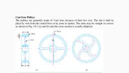
Unit 1: Belt and Rope Drives, , T. Y. BTech (Mech), , Table 1.1 Grade and tensile strength of wires., Grade of, 120, 140, 160, 180, 200, wire, Tensile, 1200 – 1500 1400 – 1700 1600 – 1900 1800 – 2100 2000 – 2400, strength, The wires are first given special heat treatment and then cold drawn in order to have, high strength and durability of the rope The steel wire ropes are manufactured by, special machines. First of all, a number of wires such as 7, 19 or37 are twisted into a, strand and then a number of strands, usually6 or 8 are twisted about a core or centre to, form the rope as shown in Fig. 1.23. The core may be made of hemp, jute, asbestos or a, wire of softer steel., , Wire strands, , Fig.1.23. Cross-sections of wire rope., The core must be continuously saturated with lubricant for the long life of the core as, well as the entire rope. The asbestos or soft wire core is used when ropes are subjected, to radiant heat such as cranes operating near furnaces. However, a wire core reduces the, flexibility of the rope and thus such ropes are used only where they are subjected to high, compression as in the case of several layers wound over a rope drum., , 1.30 Crowning of pulleys, The rim of pulley of flat belt drive is slightly crowned to prevent the slipping off the belt, from pulley. The crowning can be in form of conical surface or convex surface. Assume, that somehow a belt comes over conical portion of pulley and takes the position as, shown in fig 1.23 i.e., the center lines remains in, plane the belt will touch the rim, , Prof. Sachin M. Shinde,KECSP, , Page 29
Page 30 :
Unit 1: Belt and Rope Drives, , T. Y. BTech (Mech), , surface at its outer edge only. This is impractical .owing to pull, the belt always tend to, stick to rim surface. The belt has lateral stiffness., , Fig. 1.24., Thus a belt has to bend in the way as shown in fig 1.23 to be on the conical surface of, pulley. Let the belt travel in direction of arrow.as the belt touches the cone, the point a, on it tends to adhere to the cone surface due to pull on the belt. This means as the pulley, will take quarter turn, the point a on the belt will be carried to b which is towards, midplane of pulley than previously occupied by edge of the belt. But again, the belt, cannot stable on the pulley in upright position and has to bend to stick to cone surface,, i.e., it will occupy the position shown by dotted lines., Thus, if a pulley is made of two equal cones or of convex surfaces, the will tend to climb, on the slopes and will thus, run with its center lines on the mid plane of the pulley. The, amount of crowning is usually 1/96 of the pulley face width., , Prof. Sachin M. Shinde,KECSP, , Page 30
 Learn better on this topic