Page 1 :
Combustion in S.I. Engines, 5.1. Introduction-Definition of combustion-Ignition limits. 5.2. Combustion phenomenon-, Normal combustion-Abnormal combustion. 5.3. Effect of engine variables on ignition lag., 5.4. Spark advance and factors affecting ignition timing. 5.5. Pre-ignition. 5.6. Detonation-, Introduction-Process of detonation or knocking-Theories of detonation-Effects of, detonation-Factors affecting detonation/knock. 5.7. Performance number (PN). 5.8. Highest, useful compression ratio (HUCR). 5.9. Combustion chamber design-S.I. engines--Induction, swirl-Squish and tumble-Quench area-Turbulence-Flame propagation-Swirl ratio-, Surface-to-volume ratio-Stroke-to-bore ratio-Compression ratio (C.R.). 5.10. Some types of, mbustion chambers-Divided combustion chambers-Worked Examples-Highlights-, Objective Type Questions-Theoretical Questions., 5.1. INTRODUCTION, 5.1.1. Definition of Combustion, Combustion may be defined as a relatively rapid chemical combination of hydrogen and, carbon in the fuel with the oxygen in the air, resulting in liberation of energy in the form of heat., Following conditions are necessary for combustion to take place :, 1. A combustible mixture., 2. Some means to initiate combustion., 3. Stabilization and propagation of flame in the combustion chamber., In spark ignition (S.I.) engines, a carburettor generally supplies a combustible mixture and, the electric spark from a spark plug initiates the combustion., 5.1.2. Ignition Limits, It has been observed through experiments that ignition of charge is only possible within, certain limits of fuel-air ratio., The 'ignition limits' correspond approximately to those mixture ratios, at lean and rich, ends of the scale, where the heat released by the spark is no longer sufficient to initiate, combustion in the neighbouring unburnt mixture., • Fig. 5.1 shows the ignition limits for hydrocarbons., Practical limit for, carburetted engine, Too rich, Ignition limits for hydrocarbons, Too lean k+, 7 9, 14.5, 21, 30, Air-fuel ratio, Fig. 5.1. Ignition limits for hydrocarbons., 201, Scanned by CamScanner
Page 2 :
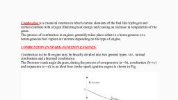
reaction and higher thermal diffusivity coefficients of the mixture., In a S.I. engine a single intensely high temperature spark passes across the electrodes, In case.of hydrocarbon fuel the stoichiometric fuel-air ratio is about 1: 15 and the fuel, The lower and upper limits of ignition of the mixture depend upon the temperature and, INTERNAL COMBUSTION ENGINES, According to Ricardo, the combustion process can be imagined as if developing in the follom., presenting a far greater area of surface from which heat is being radiated ; hence its advance is, turbulent condition. The turbulence breaks the filament of a flame into a ragged front, thus, The ignition limits are wider at increased temperatures because of higher rates, mixture immediately surrounding it at a rate which depends primarily upon the temperature of, the flame front itself and to a secondary degree, upon both the temperature and the density of the, surrounding envelope. In the actual engine cylinder, the mixture is not at rest but is in highly, leaving behind a thin thread of flame. From this thin thread, combustion spreads to the envelope, 202, mixture ratio., air ratio lies between about 1: 30 and 1:7., 5.2. COMBUSTION PHENOMENON, 5.2.1. Normal Combustion, speeded up enormously., ing two stuges :, (i) The growth and development of a self-propagating nucleus of flame (ignition Inc, is a chemical process and depends upon the following :, The nature of fuel;, The temperature and pressure;, The proportion of the exhaust gas ;, Tne temperature co-efficient of the fuel i.e., the relationship between temperature, and rate of acceleration of oxidation or burning., (ii) The spread of the flame throughout the combustion chamber., Fig. 5.2 shows the p-0 diagram of a petrol engine :, p (bar), For best performance, at 10° to 12°, Мах. pr., 40, Expansion, Ignition, advance, Compression, Qi, L, BDC 150° 120° 90° 60° 30° TDC 30° | 60° 90° 120° 150° BDC, Negative work, Positive work, Fig. 5.2. Pressure-crank angle diagram of a petrol engine., Scanned by CamScanner
Page 3 :
203, COMBUSTION IN S.I. ENGINES, LNQM assumes compression curve having no ignition., • First stage of combustion, the ignition lag, starts from this point and no pressure rise, is noticeable., • Q is the point where the pressure rise can be detected. From this point it deviates from, the simple compression (motoring) curve., The time lag between first igniting of fuel and the commencement of the main phase of, combustion is called the period of incubation or is also known as ignition lag. The, time is normally about 0.0015 seconds. The maximum pressure is reached at about 12°, after top dead centre point. Although the point of maximum pressure marks the, completion of flame travel, it does not mean that at this point the whole of the heat of, fuel has been liberated, for even after the passage of the flame, some further chemical, adjustments due to reassociation, etc., will continue to a greater or less degree throughout, the expansion stroke. This is known as after burning., Effect of engine variables on flame propagation :, 1. Fuel-air ratio. When the mixture is made leaner or is enriched and still more, the, velocity of flame diminishes., 2. Compression ratio. The speed of combustion increases with increase of compression, ratio. The increase in compression ratio results in increase in temperature which increases the, tendency of the engine to detonate., 3. Intake temperature and pressure. Increase in intake temperature and pressure in-, creases the flame speed., 4. Engine load. As the load on the engine increases, the cycle pressures increase and, hence the flame speed increases., 5. Turbulence. The flame speed is very low in non-turbulent mixture. A turbulent motion, of the mixture intensifies the processes of heat transfer and mixing of the burned and unburned, portions in the flame front. These two factors cause the velocity of turbulent flame to increase, practically in proportion to the turbulent velocity., 6. Engine speed. The flame speed increases almost linearly with engine speed. The crank, angle required for flame propagation, which is the main phase of combustion, will remain ulmost, constant at all speeds., 7. Engine size. The number of crank degrees required for flame travel will be about the, same irrespective of engine size, provided the engines are similar., 5.2.1.1. Factors affecting normal combustions in S.I. engines., The factors which affect normal combustion in S.I. engines are briefly discussed below :, 1. Inductior pressure. As the pressure falls delay period increases and the ignition, must be earlier at low pressures. A vacuum control may be incorporated., 2. Engine speed. As speed increases the constant time delay period needs more crank, angle and ignition must be earlier. A centrifugal control may be employed., 3. Ignition timing. If ignition is too early the peak pressure will occur too early and, work transfer falls. If ignition is too late the peak pressure will be low and work trans-, fer falls. Combustion may not be complete by the time the exhaust valve opens and the, valve may burn., 4. Mixture strength. Although the stoichiometric ratio should give the best results, the, effect of dissociation shown in Fig. 5.3 is to make a slightly rich mixture necessary for, maximum work transfer., 5. Compression ratio. An increase in compression ratio increases the maximum pres-, sure and the work transfer., Scanned by CamScanner
Page 4 :
maximum temperature. This mixture ratio is somewhat richer than stoichiometric, 2. Mixture ratio. Ignition lag is the smallest for the mixture ratio which gives the, 1. Fuel. Ignition lag depends on chemical nature of fuel. The higher the self ignition, Ignition lag (the time lag between first igniting of fuel and the commencement of the main, phase of combustion) is not a period of inactivity but is a chemical process. The ignition lag in, INTERNAL COMBUSTION ENGINES, 204, -Ideal combustion, Maximum, Combustion with, dissociation, Weak+, Rich, Stoichiometric, Air-fuel ratio, ->, Fig. 5.3, 6. Combustion chamber. The combustion chamber should be designed to give a short, flame path to avoid knock and it should promote optimum turbulence., 7. Fuel choice., The induction period of the fuel will affect the delay period., The calorific value and the enthalpy of vaporisation will affect the temperatures, achieved., 5.2.2. Abnormal Combustion, Due to excessively weak mixtures combustion may be slow or may be mis-timed. These are, however obvious., There are two combustion abnormalities, which are less obvious:, The first of these is pre or post ignition of the mixture by incandescent carbon, particles in the chamber. This will have the effect of reducing the work transfer., The second abnormality is generally known as knock and is a complex condition with, many facets. A simple explanation shows that knock occurs when the unburnt portion, of the gas in the combustion chamber is heated by combustion and radiation so that us, temperature becomes greater than the self ignition temperature. If normal progressve, combustion is not completed before the end of the induction period then a simultaneo, explosion of the unburnt gas will occur. This explosion is accompanied by a detonau, (pressure) wave which will be repeatedly reflected from the cylinder walls setting up, high frequency resonance which gives an audible noise. The detonation wave caule, excessive stress and also destroys the thermal boundary layer at the cylinder wes, causing overheating., Note. Refer articles 5.5 and 5.6 for details of pre-ignition and detonation respectively., 5.3. EFFECT OF ENGINE VARIABLES ON IGNITION LAG, terms of crank angles is 10° to 20° and in terms of time, 0.0015 second or so., The duration of ignition lag depends on the following factors :, temperature (S.I.T.) of fuel, longer the ignition lag., ratio., Scanned by CamScanner, Temperature -
Page 5 :
COMBUSTION IN S.I. ENGINES, 205, 3. Initial temperature and pressure. Ignition lag is reduced if the initial tempera-, ture and pressure are increased and these can be increased by increasing the compres-, sion ratio)., 4. Turbulence. Ignition lag is not much affected by the turbulence., 5.4. SPARK ADVANCE AND FACTORS AFFECTING IGNITION TIMING, Spark advance. In order to obtain maximum power from an engine, the compressed mix-, ture must deliver its maximum pressure at a time when the piston is about to commence its, outward stroke and is nearest to T.D.C. Since there is a time lag between the occurrence of spark, and the burning of the mixture, the spark must take place before the piston reaches T.D.C. on its, compression stroke, .e., the spark timing is advanced. Usually the spark should occur at about, 15° before T.D.C., The correct instant for the introduction of spark is mainly determined by the "ignition, lag". The factors affecting the ignition timings are discussed below :, 1. Engine speed. Suppose an engine has an ignition advance of 0 degrees and operating, speed in n r.p.s. Then time available for initiation of combustion is, seconds. Now if the, 360n, engine speed is increased to 2n r.p.s. then in order to have the same time available for combustion,, an ignition advance for 20 degrees is required. Thus as the engine speed is increased, it will be, necessary to advance the ignition progressively., 2. Mixture strength. In general rich mixtures burn faster. Hence, if the engine is operat-, ing with rich mixtures the optimum spark timings must be retarded, i.e., the number of crank, angle before T.D.C. at the time of ignition is decreased and the spark occurs closer to T.D.C., 3. Part-load operation. Part-load operation of a spark-ignition engine is affected by throt-, tling the incoming charge. Due to throttling a small amount of charge enters the cylinder, and the, dilution due to residual gases is also greater. In order to overcome the problem of exhaust gas, dilution and the low charge density, at part-load operation the spark advance must be increased., 4. Type of fuel. Ignition delay will depend upon the type of fuel used in the engine. For, maximum power and economy a slow burning fuel needs a higher spark advance than a fast, burning fuel., 5.5. PRE-IGNITION, Refer Fig. 5.4., • Pre-ignition is the ignition of the homogeneous mixture in the cylinder, before the, timed ignition spark occurs, caused by the local overheating of the combustible mixture., For premature ignition of any local hot-spot to occur in advance of the timed spark on, the combustion stroke it must attain a minimum temperature of something like 700-, 800°C., • Pre-ignition is initiated by some overheated projecting part such as the sparking plug, electrodes, exhaust valve head, metal corners in the combustion chamber, carbon, deposits or protruding cylinder head gasket rim etc., However, pre-ignition is also caused by persistent detonating pressure shockwaves, scoring away the stagnant gases which normally protect the combustion chamber, walls. The resulting increased heat flow through the walls, raises the surface, temperature of any protruding poorly cooled part of the chamber, and this there-, fore provides a focal point for pre-ignition., • The initiation of ignition and the propagation of the flame front from the heated hot-, spot is similar to that produced by the spark-plug when it fires, the only difference, Scanned by CamScanner