Page 1 :
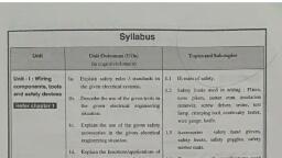
Chapter . .1, FUNDAMENTALS, CONTENTS, 1.1 Functions of Protective System, 1.2 Normal and Abnormal Conditions, 1.3 Reasons for Fault Occurrance, 1.3.1 Types of Faults, 1.3.2 Fault Statistic, 1.4 Short Circuit Calculations (Symmetrical Faults Only), 1.4.1 Symbols Used in Representing a System, 1.4.2 Single Line Diagram, 1.4.3 Percentage Reactance, 1.4.4 Base kVA, 1.4.5 Short Circuit kVA, 1.4.6 Steps in Solving Numerical Examples on Symmetrical Faults, 1.5 Use of Current Limiting Reactors and Their Arrangementm, 1.5.1 Advantages of Reactors, 1.5.2 Location of Reactors, Exercise, 1.1, The function of protective system is to disconnect the faulty part due to short circuit or to, disconnect the circuit under abnormal conditions which might cause a great damage to the rest, of the power system. For this purpose relays are used. The relay senses the fault current through, C.T. and energises the trip coil which causes the opening of C.B. of that particular system and, the faulty section is disconnected. The remaining part of the power system is not affected., The C.Bs. are located in such a way that each generator, transformer, transmission line,, feeders etc. are completely disconnected from the rest of the system till fault is cleared. The, other function of protective system is to provide indication, location of fault and type of fault., Thus fault clearing process becomes more easier., The protective system should have the following essentials properties :, 1. Very quick operation : If the protective system operates quickly and fault is cleared in a, shorter time, the components of the systems are protected from the probable damage, and insulation provided remains unaffected., 2. Reliability : The ability of the protective system to operate under the predetermined, conditions is called its reliability. It is an essential requirement for the system to be, protected., FUNCTIONS OF PROTECTIVE SYSTEM, (1-1), Scanned By Scanner Go
Page 2 :
Switchgear and Protection (Sem. - V), 1-2, Fundamentals, 3. Discrimination The protective system should have the ability to discriminate, between faulty sections and healthy sections. It should immediately isolate the faulty, section from the system without affecting the healthy section so that continuity of, supply can be maintained., 4. Provision for instruments : The protective system shall provide the proper place for the, instruments like CTs, PTs etc. on the panels easily accessible and seen for observations/, inspections., 1.2, NORMAL AND ABNORMAL CONDITIONS, (NORMAL/ABNORMAL OPERATION OF SYSTEM), 1. Normal Conditions : It is the state of the system network in which below normal or, normal current flows and voltage and frequency remains normal. The current is not diverted to, the other non-intended paths or earth and it is confined to pass in the devised path without, disturbance and the system works normally., (a) In the normal conditions the power producing device like 3-phase alternator should, run at the proper speed by the prime mover with the "speed governing arrangement" so, that it produces a desired voltage at the desired frequence (may differ by ± 1%)., (b) All the 3-phase voltages must be of equal in magnitude having phase displacement of, 120°. This is shown in the Fig. 1.1., (c) All the three live voltages VRY, VYB and VBR are also balanced and symmetrical., (d) The provision of protective system should be such that it should be most economical at, the same time it should provide satisfactory protection.COm, (e) Due to load variations impedance drop (Iz) varies which varies the voltage at the, consumer's end. It should not cross the limits of ± 5% on load top changer shall be, provided., (f) Stand by generator is provided to add into the system in peak load hours., VR, VRB, VRY, 120, 120, Vy, VBY, VB, Fig. 1.1: Balanced Condition, 2. Abnormal Conditions It is the defect in any part of the system which produce, abnormalities like, over current, over voltage, disturbance in frequencies and the elements are, likely to be damaged and system is disturbed., In the supply system, right from the generating station to consumer though the generators, produced balance symmetrical 3-phase voltages. The operation becomes abnormal due to, various faults in the system as mentioned below. Due to abnormalities following are the defects, observed :, Scanned By Scanner Go
Page 3 :
Switchgear and Protection (Sem. - V), 1-3, Fundamentals, (a) Voltage and current unbalanced, (c) Reversal power, (e) Under frequency, (g) Unstability of system., (b) Over voltages, (d) Power swinging, (f) Temperature rise, 1.3, REASONS FOR FAULT OCCURRENCE, 1. Due to failure of insulation of components and equipment parts. It may lead to short, circuit., 2. Due to mechanical injuries and over temperature conductor may break., 3. Lightnings and switching surges may damage the transmission and distribution lines., Lines are also affected by birds and objects, trees falling on them or due to wind pressure., 4. Harmonics produced in rotating machines due to unbalanced currents produce over, heating., 5. Drawbacks in system designing, lack of selection of good quality material, equipment, machinery, protective elements etc. may cause damage to the system., 6. Due to mal-operation by operators., 7. Earthquakes, lightning, storms, ice forming are also responsible to disturb the system., 1.3.1 Types of Faults, Types of Faults, Symbols, Causes, 1. Single line to ground, fault., One line any how touches to, ground or support., OBookangacom, Two lines connected together, due to insufficient distance or, 2. Line to line fault., Fault, wind pressure., 3. Double line to ground, fault., Two conductors touches, together and touches to, ground or pole/tower., All the three lines make, contact in abnormal situation, such as storm, falling of trees., 4. Three phase short circuit., Fault, 5. Open circuit fault., Open, Conductor may be broken., Two conductors touches and 3rd, conductor touches to support/, 6. Simultaneous faults., tower., Fig. 1.2: Types of Fault, Scanned By Scanner Go
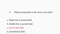
Page 4 :
Switchgear and Protection (Sem. - V), Fundamentals, 1-4, 1.3.2 Fault Statistic, Due to various causes as explained above following is the collected statistical data for, faults on various elements., Table 1.1, Sr. No., Element, % Total Faults, 1., O.H. Lines, 50%, 2., Under Ground Lines (cables), 9%, 3., Generators, 7%, 4., Transformers, 10%, 5., Switchgears, 12%, 6., Protective devices like CT,, 12%, PT, relay etc., Table 1.2, Sr. No., Types of Fault, % Total Faults, 1., Line to ground, 85%, 2., Line to line, 8%, 3., Line to line to ground, 5%, 2% very rare, 1.4, SHORT CIRCUIT CALCULATIONS (SYMMETRICAL FAULTS ONLY), Most of the faults in power systems are due to short circuits which lead to a very heavy, short circuiting current which may damage the equipments. Hence, it becomes necessary to, determine the S.C. currents which enable us to determine the capacity of C.B. relays, C.Ts. etc., The faults may be (1) Symmetrical, (2) Unsymmetrical., 1. Symmetrical Fault : In the system, if the short circuit currents are equal in different, conductors, if the short circuit occurs in both the conductors of a single phase line or across three, wires in a 3-phase system, then the fault is a symmetrical fault. Current in all conductors are, equal in magnitude and displaced by 120°., 2. Unsymmetrical Fault : The fault in a 3-phase system which occurs across the two of the, three-phases or between one or two-phases and earth causing unequal currents in the conductors, is called as an unsymmetrical fault., Our study is limited to calculations of S.C. currents in symmetrical faults only. The, calculations become less laborious because of the balanced nature of fault. Only one phase need, to be considered in calculations. The results of the other two will be same., Note that most of the faults are unsymmetrical whereas the symmetrical faults are rare., Symmetrical faults are most severe and hence C.B. shall be of bulk capacity., Scanned By Scanner Go