Page 1 :
KAS 101T, , Engineering Physics, Unit-4-Wave Optics, , CO4, , INTERFERENCE, 4.1 Coherent Sources, It is found that it is not possible to show interference due to two independent sources of light because a, large number of difficulties are involved. Two sources may emit light wave of different amplitude and, wavelength and the phase difference between the two may change with time. The fundamental, requirement to get will defined interference pattern is that the phase difference between the two waves, should be constant. The two sources are said to be coherent if they emit light waves of same, frequency nearly the same amplitude and are always in phase with each other., There are two type of coherence, 1. Temporal coherence (Coherence in time): Longitudinal coherence is also known as temporal, coherence. It is a measure of phase relation of a wave reaching at given points at two different, times. Example- In Michelson-Morley experiment waves reaching at a given point at the same, time., 2. Spatial coherence (Coherence in space): Transverse coherence or lateral coherence is also known, as spatial coherence. It is a measure of phase relation between the waves reaching at two different, points in space at same time. Example- In Young double slit experiment waves reaching at two, different points in space at the same time., In actual practice it is not possible to have two independent sources which are coherent. But for, experimental purpose two virtual sources formed from a single source can act as coherent sources., A coherent source forms sustained interference patterns when superimposition of waves occur and the, positions of maxima and minima are fixed., Methods for producing interference pattern: It is divided in following two classes for obtaining, , interference, Division of wave front: interference of light take place between waves from two sources formed due to, single source. Example interference by Young double slit., Division of amplitude : interference takes place between the waves from the real source and virtual, source. Example interference by thin film, , 4.2 Interference in thin film, An optical medium of thickness in the range of 0.5, Interference can take place in a thin film by, i), Interference due to reflected light, ii), Interference due to transmitted light, 53, , to 10, , may be considered as thin film.
Page 2 :
KAS 101T, , Engineering Physics, Unit-4-Wave Optics, , CO4, , 4.3 Interference in a Thin Film Due to Reflected Light, transparent film of uniform thickness t as shown in the fig. The ray SA is partly reflected along AB and, partly refracted along AC at an angle r. The refracted ray AC is reflected from point C on the lower, surface of the film along CD and finally emerges out along DE. To evaluate the path difference between, AB & DE draw perpendiculars DL & CN on AB & DE respectively. As the paths of the rays AB & DE, beyond DL are equal so the optical path difference between these two rays is given by, µ(AC+CD)-AL -------------- (1), In right angled triangle CNA we have, Ac =, , =, , = cos r or, , -------------- (2), , ACN =r and CN =t, similarly in another right-angled triangle CND, we have, , = cos r or CD =, , =, , -- --(3), , where NCD =r, In right angled triangle ADL sin i =, , or AL = AD Sin i = (AN+ND)Sin i ------- (4), , Again in triangles CNA & CND, , = tan r and, , = tan r, , AN = NC tan r and ND= NC tan r, AN = t tanr and ND = t tan r, From equation (4) AL= 2t tan r (Sin i), , AL = 2 µt, , ------------ (5), , Substituting the values in equation (1), +, Hence,, , ) - 2 µt, -------------------- (6), , As the ray AB is reflected from the denser medium therefore there occurs an additional path difference of, between AB and DE., -, , ------------------- (7), 54
Page 3 :
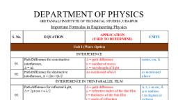
KAS 101T, , Engineering Physics, Unit-4-Wave Optics, , CO4, , This is the actual path difference produced between interfering reflected rays AB and DE., Condition for constructive interference and destructive interference, Constructive interference (Condition of Maxima ):, , In the case of maxima, the path difference will be even mu, 2 µt cos r-, , 2 n( /2), , 2 µt cos r-, , This is the condition for constructive interference and the film will appear bright., Destructive interference (Condition of Minima ):, , In the case of maxima, the path difference will be odd, 2 µt cos r2 µt cos r = n, , This is the condition for destructive interference and the film will appear dark., , 4.4 Interference in a Thin Film Due to Transmitted Light, thickness t and refractive index µ at an angle i as shown in fig. The ray SA is refracted along AB at an, angle r. The refracted part AB is partly reflected along BC and partly refracted along BP at an angle i. The, reflected part BC is again reflected from point C on the upper surface of the film along CD and finally, emerges out along DQ, which are derived from the same incident ray and hence are coherent. To evaluate, the path difference between BP & DQ the, perpendiculars DN & CM are drawn on BP & BD, respectively., - BN, , --- (1), , In right angled triangle CBM we have, BC =, , =, , = cos r or, , ----(2), , BCM =r and MC =t, similarly, in another right-angled triangle MDC, 55
Page 4 :
KAS 101T, , Engineering Physics, Unit-4-Wave Optics, we have, , = cos r or CD =, , CO4, =, , -- --(3) where MCD =r, , In right angled triangle BND sin i =, , or BN = BD Sin i = (BM+MD) Sin i, , Again, in triangles BMC & CDM, , = tan r and, , ---- (4), , = tan r, , BM = CM tan r and MD= CM tan r, BM = t tan r and MD = t tan r, From equation (4) BN= 2t tan r (Sin i), BN = 2t tan r (µ Sin r), BN = 2 µt, , ---- (5), , Substituting the values in equation (1), +, , ) - 2 µt, ------ (6), , This is the path difference produced between interfering refracted rays BP and DQ., Condition for constructive interference and destructive interference, Constructive interference (Condition of Maxima ):, , In the, , This is the condition for constructive interference and the film will appear bright., Destructive interference (Condition of Minima ):, , In the case of maxima, the path difference will be odd, 2 µt cos r = (2n +, , This is the condition for destructive interference and the film will appear dark. Hence the conditions of, maxima and minima in transmitted light are just opposite to the reflected light., 56
Page 5 :
KAS 101T, , Engineering Physics, Unit-4-Wave Optics, , CO4, , Colours of thin films: When white light is incident on a thin film only few wavelengths will satisfy, the condition of maxima and therefore corresponding colours will seen in the pattern. For other, wavelengths condition of minima is satisfied, and so corresponding colours will be missing in the pattern., The coloration of film varies with t and r. Therefore, if one varies either t or r a different set of colours, will be observed. Since the condition for maxima and minima are opposite in case of reflected and, transmitted pattern. So the colours found in two patterns will be complimentary to each other., , 4.5 Necessity of broad source or extended Source: When point source is used only a small, portion of the film can be seen through eye and as a result the whole interference pattern cannot be seen., But when a broad source is used rays of light are incident at different angles and reflected parallel beam, reach the eye and whole beam and complete pattern is, visible., , 4.6 Interference Due to non-uniform Thin film, (Wedge shaped thin film), The wedge-shaped film as shown in Figure 4.5. Let a ray, from S is falling on the film and after deflections produce, interference pattern. The path difference between PQ and EH, film, , - (PK)air], , = µ (PF + FE) (PK), = µ (PN + NF + FE) PK, *In triangle PKE, , = µ (PN + NF + FE PN)*, , In triangle PNE,, , = µ (NF +FE), , =µ, , = µ (NF + FL) **, , NL = EL Cos(, , = µ , then PK = µPN, , **In triangles EFR & FRL, FR is common, ER= RL=t, , = µ (NL), In Triangle ENL, , *, , = Cos(, ) = 2t Cos(, , ), ), , Therefore, Then total path difference considering refraction from denser medium is taking place, , 57
Page 6 :
KAS 101T, , Engineering Physics, Unit-4-Wave Optics, , CO4, , Condition for maxima, where, This is the condition for constructive interference and the film will appear bright., Condition for minima, where, This is the condition for destructive interference and the film will appear dark., , 4.7, It is a special case of interference in a film of variable thickness such as that formed, between a plane glass plate and a convex lens in contact with it. When monochromatic light falls over it, normally we get a central dark spot surrounded by alternatively bright and dark circular rings. When, white light is used the rings would be coloured., Experimental Arrangement: Let S be the extended, source of light, rays from which after passing through a, lens L falls upon a glass plate Gat 45°. After partial, reflection these rays fall on a plano convex lens P placed, on the glass plate E. The interference occurs between the, rays reflected from the two surfaces of the air film and, viewed through microscope M as shown Figure., Theory: The air film formed is of wedge shape so the, path difference produced will be, ,, For normal incident r = 0 and is very small because of large radius of curvature, So neglecting r and, the path difference will be, So, , = 2 µt-, , At the point of contact t = 0, So, , , The central fringe will be dark., , Condition for maxima :, , where n = 0, 1, 2, 58
Page 7 :
KAS 101T, , Engineering Physics, Unit-4-Wave Optics, , CO4, , This is the condition for constructive interference and the film will appear bright., Condition for minima:, , where n = 0, 1, 2, This is the condition for constructive interference and the film will appear bright. we get alternatively, bright and dark rings., Diameter of the rings:, , NP x NQ = ND x NO, NP= NQ= r, radius of ring under consideration., NO =t, ND= OD-ON, OD= 2R, r2= t (2R- t) = 2Rt- t2 = 2Rt, , Then, , t = r2/2R, Diameter of bright rings, , : From the condition of maxima put the, , value of t we get, =, r2n =, Dn2, , =, =, , Dn2 = 2, , (For air, µ = 1), , Dn, Dn, Thus, the diameter of bright rings are proportional to the square root of the odd natural numbers., Diameter of dark ring, , : Using the condition for minimum and put the value of t, , 59
Page 8 :
KAS 101T, , Engineering Physics, Unit-4-Wave Optics, , CO4, , which gives, (Dn)2, Or Dn =, Dn, Thus, the diameter of dark rings are proportional to the square root of natural numbers., , 4.8, 4.8.1 Measurement of Wavelength of sodium, For dark rings we know that, , To avoid any mistake one can consider two clear fringes nth and (n + p)th, So,, , (Dn)2 = 4n, (Dn+p)2, , --------(1), ------(2), , Subtracting these two equation we get ((Dn+p)2 - (Dn)2) = 4, Or, Wavelength can be calculated if you know diameters of the rings, order of the ring and radius of curvature, (R), , 4.8.2 Measurement of, For this purpose liquid film is formed between the lens and glass plate., For dark rings we know that, To avoid any mistake one can consider two clear fringes nth and (n + p)th, So,, , (Dn)2 =, , and (Dn+p)2 =, , 60
Page 9 :
KAS 101T, , Engineering Physics, Unit-4-Wave Optics, , CO4, , Subtracting these two we get [(Dn+p)2 - (Dn)2)]liquid =, , -----(1), , For air µ=1, equation (1) can be written as [(Dn+p)2 - (Dn)2)]air = 4p, Divide equation (2) by equation (1), , One can see that rings contract with the introduction of liquid., , 61, , -----(2)
Page 10 :
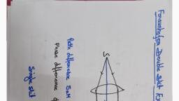
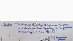
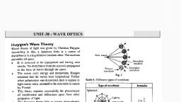
KAS 101T, , Engineering Physics, Unit-4-Wave Optics, , CO4, , DIFFRACTION, The phenomenon of bending of light round the corners of an obstacle and their spreading into the, geometrical shadow (of an object) is called diffraction and the distribution of light intensity resulting in, dark and bright fringes (that is, with alternate maxima and minima) is called a diffraction pattern., This phenomenon was first discovered in 1665 by an Italian scientist named Grimaldi and was studied by, Newton. Fresnel was able to explain successfully the phenomenon of diffraction by considering that the, diffraction phenomenon is caused by the interference of innumerable secondary wavelets produced by the, unobstructed portions of the same wave front., The diffraction phenomenon is usually divided into two categories:, In this class either the source of light or screen or both are in general at a finite, distance from the diffracting element but no lenses are needed for rendering the rays parallel or, convergent. Therefore the incident wave front is either spherical or cylindrical instead of being plane., In this class both the source and the screen are effectively at infinite, distance from the diffracting element. It is observed by employing two convergent lenses: one to render, the incoming light parallel and the other to focus the parallel diffracted rays on the screen. Therefore the, incident wave front is plane., , 4.9 Fraunhofer diffraction at a single Slit, , is focused at the screen. A diffraction pattern is obtained on the screen which consists of central bright, band having alternate dark and bright bands of decreasing intensity on both the sides. The complete, arrangement is shown in Figure., Analysis, , and Explanation: According to, heory a point in AB send out secondary, waves in all directions. The diffracted ray along, the direction of incident ray is focussed at C and, at equidistant from all slits points, secondary wave, will reach in same phase at point C and so the, intensity will be maximum there. For the intensity, at P, let AN is normal to BN, then path difference, between the rays emanating from extreme points, A and B of the slit AB is given by, 62
Page 11 :
KAS 101T, , Engineering Physics, Unit-4-Wave Optics, , CO4, , Corresponding phase difference is, , 2, , a sin, , which is zero for the ray from A and maximum for the ray from B. Let AB consists of n secondary, sources then the phase difference between any two consecutive source will be, 1 2, a sin, n, According to the theory of composition of n simple harmonic motions of equal amplitude (a) and, common phase difference between successive vibrations, the resultant amplitude at P is given by, sin, R, , a, , n, 2, , sin, , R, , R, , na, , sin a sin, sin a sin, , n, , 2, , sin, , a, , sin, R, , a, , a sin, n, , n, , sin, , A sin, , Where A=, , (1), , The resultant intensity at P, which is the square of the resultant amplitude R, is given by, I = R2 = A2 sin2, , 2, , ...................................................... (2), , Condition of Maxima and Minima, , Principal Maximum(central maxima), The resultant amplitude given by equation (1) can be expanded as, R, , A sin, , A, , 3, , 6, , 5, , 120, , ........., , 63
Page 12 :
KAS 101T, , Engineering Physics, Unit-4-Wave Optics, , CO4, , the maximum value of resultant amplitude R at C is A and the corresponding maximum intensity is, proportional to A 2 ., Positions of Minima, From, Then, , , 2 , 3 ......... n ,, a sin, n, a sin, , n, , Where n=1,2,3..... gives the directions of first, second, third,...... minima., Secondary Maxima, from equation (2) secondary maxima will be,, , =0, , =>, , [A2 sin2, , 2, , ]=0, , A2, i.e either, the equation, gives the value of (except, for which the, intensity is zero on the screen. Hence position of secondary maxima are given by the roots of the equation, , The value of satisfying the above equation are obtained, graphically by plotting the curves, , The point of intersection of two curves give the value of, which satisfy the above equation, ., The point of intersection will give, , 64
Page 13 :
KAS 101T, , Engineering Physics, Unit-4-Wave Optics, , CO4, , =0,, The first value, maxima., , ., , Intensity Distribution:, , a) Intensity of Central Maxima: at,, I= Lt A2 [ sin2, , 2, , ]= A2 = I0, , b) Intensity of First Secondary Maxima: for first(n=1) secondary maxima,, (2) will be, I1 = A 2, , 2, , 2, , = 4 I0, , 2, , = I0 /22, , c) Intensity of second Secondary Maxima: for second(n=1) secondary maxima,, equation (2) will be, I2 = A 2 (sin 5, , 2, , /(5, , 2, , = 4 I0, , 2, , = I0 /62, , The diffraction pattern consists of a bright central maximum surrounded by minima and the intensity of, secondary maxima goes on decreasing very rapidly., , 4.10, Let us suppose two parallel slits AB and DE each of wi, , a, , b . Let a, , light diffracted by the slits be focused by a convex lens L on the screen XY situated in the focal plane of, the lens. The diffraction pattern obtained on the screen is characterized by a number of equally spaced, interference maxima and minima in the region normally occupied by the central maximum in the single, slit diffraction., 65
Page 14 :
KAS 101T, , Engineering Physics, Unit-4-Wave Optics, , CO4, , Explanation: According to the theory of diffraction at a single slit, the resultant amplitude due to all the, wavelets from each slit is given by, A sin, , R, , ,, , ............... (1), , We can replace all secondary waves from the slit AB by a, middle point S1. Similarly all the secondary wavelets in the, second slit DE can also be replaced by the similar wave originating from its middle point S2. Hence the, resultant amplitude at a point P on the screen will be due to, the interference between the two waves of same amplitude, S1 and S2., Let us drop a perpendicular S1M on S2M. The path, difference between the two wave originating from S1 and, S2, be, S2, , (3), , Therefore the corresponding phase difference between, them is, 2, , a b sin, , .......................... (4), , The resultant amplitude at P can be obtained by the vector amplitude diagram QR and RS represent the, amplitude of the two waves originating from S1 and S2, QS 2, R, , QR 2, , ,2, , R, , 2, , RS 2, R, , 2, , 2, , 2 R (1 cos ), 4 R 2 cos 2, , 2(QR)( RS ) cos, , 2 R.R. cos, .................................. (5), , 2, , 66
Page 15 :
KAS 101T, , Engineering Physics, Unit-4-Wave Optics, R '2, , 4 A2, , sin 2, , cos 2, , 2, , (6), , a b) sin, , 2, , CO4, , (7), , Therefore, the resultant intensity at P is, , I, , R '2, , 4A 2, , sin 2, 2, , cos 2, , ................... (8), , This is the required expression for the intensity distribution d, slit., It is clear from equation (8) that the resultant intensity at any point on the screen depends on two factors:, 1., , sin 2, 2, , which gives diffraction pattern due to each single slit, , 2. cos 2 which gives the interference pattern due to two waves of same amplitude (R) originating, from the mid-points of their respective slits., Hence the resultant intensity, due to double slit of equal width, at any point on the screen is given by, sin 2, the product of, and cos 2 . If either of these factor is zero, the resultant intensity will also be, 2, zero. Let us now consider the effect of each factor., Principal maxima is given by A2, , (i), , sin 2, 2, , Position of minima are given by, -zero, , m=1,2,3............, , m, , a sin, sin, , m, m, a, , , m=1,2,3..........., , Position of secondary maxima approach to, 67
Page 16 :
KAS 101T, , Engineering Physics, Unit-4-Wave Optics, , CO4, , 3, 5 7, ,, ,, ,.........., 2, 2 2, According to interference term, cos 2, , (ii), n, , a, a, , ,, , =1, , n=0,1,2,3........., , b sin, b sin, , , I is maximum when cos 2, , n, , n=0,1,2,3.........................., , n, , Intensity is minimum when cos 2, a b sin, , Thus, the entire pattern due to double slit may be considered as consisting of interference fringes due, to light from both slits. The intensities of these fringes being governed by diffraction occurring at the, individual slits., 68
Page 17 :
KAS 101T, , Engineering Physics, Unit-4-Wave Optics, , CO4, , 4.11 Plane Transmission Diffraction Grating (N-Slits Diffraction/Diffraction due, to double slits), A plane diffraction grating is an arrangement consisting of a large number of close, parallel, straight,, transparent and equidistant slits, each of equal width a, with neighbouring slits being separated by an, opaque region of width b. A grating is made by drawing a series of very fine, equidistant and parallel lines, on an optically plane glass plate by means of a fine diamond pen. The light cannot pass through the lines, drawn by diamond; while the spacing between the lines is transparent to the light. There can be 15,000, lines per inch or more is such a grating to produce a diffraction of visible light. The spacing (a + b), between adjacent slits is called the diffraction element or, grating element. If the lines are drawn on a silvered surface of, the mirror (plane or concave) then light is reflected from the, positions of mirrors in between any two lines and it forms a, plane concave reflection grating. Since the original gratings, are quite expensive for practical purposes their photographic, reproductions are generally used., The commercial gratings are produced by taking the, cast of an actual grating on a transparent film such as cellulose, acetate. A thin layer of collodin solution (celluloid dissolved in a volatile solvent) is poured on the surface, of ruled grating and allowed to dry. Thin colluding film is stripped off from grating surface. This film,, which retains the impressions of the original grating, is preserved by mounting the film between two glass, sheets. Now-a-days holographic gratings are also produced. Holograpic gratings have a much large, number of lines per cm than a ruled grating Theory of Grating: Suppose a plane diffraction grating,, consisting of large number of N parallel slits each of width a and separation b, is illuminated normally by, a plane wave front of monochromatic light of wavelength A. as shown in Figure . The light diffracted, through N slits is focused by a convex lens on screen XY placed in the focal plane of the lens L. The, diffraction pattern obtained on the screen with very large number of slit consists of extremely sharp, principle interference maximum; while the intensity of secondary maxima becomes negligibly small so, that these are not visible in the diffraction pattern. Thus, if we increase the number of slits (N), the, intensity of principal maxima increases., Explanation, , , all points within each slit become the source of secondary wavelets,, which spread out in all directions. From the theory of Fraunhofer diffraction at a single slit, the resultant, A sin, s given by R, , where A, h, waves, each starting from the middle points S1, S2, S3,.... Sn-1, Sn of slits. Draw perpendicular S1Kn-1 from, S1 on SnKn-1, then the path difference between the waves originating from the slits S1 and S2 is, 69
Page 18 :
KAS 101T, , Engineering Physics, Unit-4-Wave Optics, , CO4, , S2K1=S1S2, Similarly, between rays from S2 and S3 will be, S3K2=S2S3 sin, Therefore the, increases in arithmetical progression. therefor the problem reduces to, A sin, find the resultant amplitude of N waves of equal amplitude R, and period but the phase, given by, , R', , R, , sin N, sin, , A, , sin, , ., , sin N, sin, , The corresponding intensity at P is given by, , I, , R '2, , A 2 sin 2, 2, , ., , sin 2 N, ., sin 2, , The first factor of equation (1), that is, , ................ (1), , A2 sin 2, 2, , represents intensity distribution due to diffraction at a, , sin 2 N, gives the distribution of intensity in the, sin 2, diffraction pattern due to the interference in the waves from all the N slits., single slit, whereas the second factor. That is,, , Principal maxima:, , The condition for principal maxima is, , = 0 and equation (1) gives the direction of zero, , by putting n = 1, 2, 3, . .. in equation (1)., Minima: The intensity is minimum, when, 70
Page 19 :
KAS 101T, , Engineering Physics, Unit-4-Wave Optics, , CO4, , Th, , gives the positions of principal maxima. Positive and negative signs show that the minima lie, symmetrically on both sides of the central principal maximum. It is clear from equation (2) that form= 0,, we get zero order principal maximum, m = 1, 2, 3,4, = (N -1) gives minima governed by equation (2) and, then at m = N, we get principal maxima of first order. This indicates that, there are (N -1) equispaced, minima between zero and first orders maxima. Thus, there are (N 1) minimum between two successive, principal maxima., Secondary Maxima: The above study reveals that there are (N- 1) minima between two successive, principal maxima. Hence there are (N -2) other maxima coming alternatively with the minima between, two successive principal maxima. These maxima are called secondary maxima. To find the positions of, the secondary maxima, w, 2, , sin2 a /a2, , -, , To find the intensity of secondary maximum, we make, these of the triangle shown in Figure., 2, tan 2, Therefore sin 2, sin 2, , 2, , 2, 2, , 2, , tan 2, , tan 2, , 2, 2, , 2, , tan 2, , ) /sin 2, , = N 2(1+n2 sin 2, Putting this value of sin 2, IS =A2 sin 2, , 2, , 2, , =N2/[1+(N2-1) SIN2, , This indicates the intensity of secondary maxima is, proportional to, N 2 /[1+(N2-, , whereas the intensity of principal maxima is proportional to N2., 71
Page 20 :
KAS 101T, , Engineering Physics, Unit-4-Wave Optics, , CO4, , 4.12 Absent Spectra with a Diffraction Grating, It may be possible that while the first order spectra is clearly visible, second order may be not be visible at, all and the third order may again be visible. It happen when for again angle of diffraction 0, the path, difference between the diffracted ray from the two extreme ends of one slit is equal to an integral multiple, of A if the path difference between the secondary waves from the corresponding point in the two halves, will be A/2 and they will can all one another effect resulting is zero intensity. Thus the mining of single, slit pattern are obtained in the direction given by., , If the two conditions given by equation (2) are simultaneously satisfied then the direction in which the, grating spectrum should give us a maximum every slit by itself will produce darkness in that direction and, hence the most favourable phase for reinforcement will not be able to produce an illumination i.e., the, resultant intensity will be zero and hence the absent spectrum. Therefore dividing equation (2) by, equation (1), , (a+ b) /a =n/m, This is the condition for the absent spectra in the diffraction pattern, If a= b i.e., the width of transparent portion is equal to the width of opaque portion then, from equation (3) n = 2m i.e., 2nd, 4th, 6th etc., orders of the spectra will be absent corresponds to the, minima due to single slit given by m = 1, 2, 3 etc., b = 2a & n=3m, i.e., 3rd, 6th, 9th etc., order of the spectra will be absent corresponding to a minima due to a, single slit given by m = 1, 2, 3 etc., , 4.13 Number of Orders of Spectra with a Grating, The number of spectra that are visible in a given grating can be easily calculated with the help, of the equation., 72
Page 21 :
KAS 101T, , Engineering Physics, Unit-4-Wave Optics, , CO4, , Here (a+ b) is the grating element and is equal to 1/N = 2.54 N cm, N being number of lines per inch in, maximum possible order of spectra., N max, If (a + b) is between, n max, and hence only the first order of spectrum is seen., , 4.14 Dispersive Power of a plane diffraction grating, The dispersive power of a diffraction grating is defined as the rate of change of the angle of diffraction, with the change in the wavelength of light used., , For plane diffraction grating, we have the grating equation for normal incidence as, , th, , (a b) cos, Therefore, the dispersive power,, , d, d, , n, a b cos, , ........................................ (2), , 73, , d, d, , n, , order spectrum.
Page 22 :
KAS 101T, , Engineering Physics, Unit-4-Wave Optics, d, d, , n, 1, , a b 1 sin, n, 1, , n, a b, , a b 1, d, d, , CO4, , 2, , 2, , 1, a b, n, , 2, 2, , separation between two spectral lines with difference in, , 4.15 Resolving Power of Optical Instruments, When two objects are very class to each other, it may not be possible for our eye to see them separately. If, we wish to see them separately, then we will have to make use of some optical instruments like, microscope, telescope, grating, prism etc. The ability of an optical instrument to form distinctly separate, images of two objects, very close to each other is called the resolving power of instrument. A lens system, like microscope and telescope gives us a geometrical resolution while a grating or a prism gives a spectral, resolution. In fact the image of a point object or line is not simply a point or line but what we get is a, diffraction pattern of decreasing intensity. For a two point system two diffraction patterns are obtained, which may and may not overlap depending upon their separation. The minimum separation between two, objects that can be resolved by an optical instrument is called resolving limit of that instrument. The, resolving power is inversely proportional to the resolving limit., , 4.15.1 Rayleigh Criterion of Resolution, position of central maximum of one coincides with the first minima of the other or vice versa., , 74
Page 23 :
KAS 101T, , Engineering Physics, Unit-4-Wave Optics, , CO4, 1, , -, , 1, 2 There may be, ), is, sufficiently, large, so, that, central, maximum, are quite, 2, , due to one falls on the first minima of the other. The resultant intensity curve shows a distinct dip in the, middle of two central maxima. This situation is called just resolved as the intensity of the dip can be, resolved by our eyes., ldip = 0.81 Imax, 1- 2) is very small such that they come still closes as shown in Figure. The intensity, curves have sufficient overlapping and two images cannot be distinguished separately. The resultant curve, almost appears as one maxima. This case is known as unsolved. Thus the minimum limit of resolution is, that when two patterns are just resolved., , 4.15.2 Resolving Power of Plane Diffraction Grating, We know that the diffraction grating has ability to produce spectrum i.e., to separate the lines of nearly, equal wavelengths and therefore it has resolving capability. The resolving power of a grating may be, defined as its ability to form separate diffraction maxima of two wavelengths which are very close to each, other. If A. is the mean value of, Expression for resolving power:, 1, 2 is falling, normally on a grating AB which has (a + b) grating element and N number of slits as shown in Figure·., After passing through grating rays forms the diffraction patterns which can be seen through telescope., Now, if these patterns are very close together they overlap and cannot be seen separately. However, if, they satisfy the Rayleigh criterion, that is the wavelengths can be just resolved when central maxima due, to one falls on the first minima of the other., Let the direction of nth principal maxima for wavelength, A.1 is given by, n, , l, , n, , 1, , and the first minima will be in the direction given by, n, , n, , 1, , these values condition of maxima will be, satisfied. The first minima adjacent, , n, , when m = (nN + 1). Thus, 75, , n, , ) only
Page 24 :
KAS 101T, , Engineering Physics, Unit-4-Wave Optics, n, , CO4, , n, , 1, , Therefore, , n, , n, , or, , 2, , n, , n, , 2, , Now equating the two equations, or, , 1, , 2, , -, , 1, , (nN + 1), , 2, , Thus resolving power of grating is found as, , Resolving power = order of spectrum x total number of lines on grating which can also be written as, /, , n, , where, m= N(a +b) is the total width of lined space in grating., R .P. MAX =, , when, , n=, , 90°, , Relation between Resolving Power and Dispersive Power of a Grating, , We know that resolving power,, and dispersive power, Therefore,, , n, n, , n, , Resolving power = total aperture of telescope objective x dispersive power., The resolving power of a grating can be increased by, (i) Increasing the number of lines on the grating N., (ii) Increasing the sides of spectrum n., telescopes objective., 76