Page 1 :
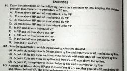
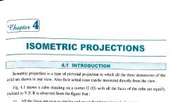
Unit I, orthographic Pojections, , 7, , orthographic Projections, 7.1, , NTRODUCTON, , length, breadth and thickness. In graphic language, te, of the object formed by rays ofsight, sapeof an ojrt is desrid by prjection which is the inmage, Any otit has thee dinensicns ie,, , taken in same partiular dirxtion trom the okjxt into a picture plane, as it appears to an observer, , sainad at the point frnor towarnds which the prjection is made. The following are the elemenb to, , ecorsidernd while drawing a projertion:, () The plane of projection, , Theobjt, , (i)The lines of sight, , Thepoint ofsight, 72, , METHODS OF PROJECTIONS, , hanngineering drawirng four methods of projections are generally used which are as follows:, () Axonometric Projections, Cthographic Projections, , () Ferspective Projections, (0ique, Projections, In the orthographic prnjections, an object is represented by two or more than two views on the, utual perpendiularplanes of projections or picture planes. Each view represents two dimensions, , of an ajeci. For the complete description of the thre dimensional object, at least two views are, eqied, , Inthe other three methods, the objects are represented by a pictorial view only. In these methods, of projections, a three dimensional object is represented on a projection plane by single view only., , 73, , PLANES OF PROJECTION, The plane on which the projection is taken is called as plane of projection or picture plane. in, , orthographic projections, three planes are used for getting the different views of an object. One is set, , up in the vertical position is called the Vertical Plane (VP) or Frontal Plane (FP). The second, set up in, horizantal position ie. perpendicular to the VP, is called Horizontal Plane (HP). The third plane, se, , up perpendicular to both HP and VP is called Profile Plane (PP)., , Both horizontal and vertical planes, which are called as principal planes, divide the whole spa, 5de ot the profile plane in four parts, called the four dihedral angles or quadrants as shown, , Fe7.1. Thelines of intersection of these three planes are called coordinate axes. The line of intersection, , of HP and VPis commonly called as reference line and is generally denoted by the letters zy. The, , projection, , on VPis alled the front, , view, , orelevation of the object. The projection, , on HP is called the
Page 2 :
ORTHOGRAPHIC PROJECTIONS, view or plan of the object. The, n, top, v, , elevati, wation of the object., , projection on the PP is called the side view or end, of, , The point intersection of the three, coordinate, , po, ends of lines, corners, this book, actual points,, of, , 87, , view or ena, , planes is called the origin. n, solids etc. inspace, are denoted by capital letters A, B,, st, , Cetc, Their top views or plan are marked, by corresponding small letters a, b, cetc. and front, olevation by small letters with dashes a',, views, The side views or, mall letters with double dashes a", b", b',cetc., are denoted, elevation, end, d' etc. These are the standard conventions that will be, used throughout in this book., , orelev, b y sma, , Vertical Plane (VP), Profile Plane (PP), , 2d Quadrant 1, , Quadrant, Horizontal Plane (HP), , 3 Quadrant, , 7.4 FOUR QUADRANTS, , 4 Quadrant, , Fig. 7.1 Three planes of projections, , When the planes of projections are extended, four, beyond the line of intersection, objectform, quadrants or dihedral angles, which may be numbered as shown in Fig. 7.2. Thethey, may be, situated in any one of the quadrants, its relative position to the planes being described as 'above or, below the HP and 'infront of or behind the VP'., VerticalPlane( V P ) /, , Second Quadrant, Above HP, Behind VP, , First Quadrant, Above HP, Infront of VP, Reference LIne, Horizontal Plane (HP), , Second Angle, Third Angle, , First Angle, , Fourth Angle, Fourth Quadrant, , Third Quadrant, , Below HP, , Below HP, Behind VP, , Infront of VP, , Fig. 7.2 Four quadrants
Page 3 :
cOMPUTER AIDED ENGINEERING GRAPHI, , 88, , HICS, , when theohi, second angle, third angle, iourth angle, A projection is said to be the first angle,, or, fourth, quadt, second quadrant, third quadrant, to be either in first quadrant,, or, , imagined, in one plane by holding VP and rotatinaht, are made to lie, two, planes, The, principal, respectively., first and third angle projections are, two systems i.e., the, through 90°, clockwise. However, only, out while rotating the planesbeing, TL, are always opened, third, The, and, quadrants, first, because, only, followed,, Whereas in second and fourth quadrants t, these quadrants., the, positions of views donot overlap in, fourth angle projections are not used., and, second, is, That, is, , why, , positions of views overlap., 7.5, , FIRST-ANGLE PROJECTION, , to be positioned in first quadrant. The front view, ew is, In first-angle projection, an object is imagined, this case, the objectwill be in betwe, In, of, side, quadrant., veen, obtained by looking at the object from right, , observer and plane of projection., obtained by looking at the object, normal to its surface. A., Similarly, top view and side view are, so two possible views from the side ie., leh, there are two sides for an object (left side and right side),, for any object., side view and right side view may be obtained, , In the first-angle projection, a left side view is obtained on the proile plane by placing it to the, projection any view is so placed that it represents the side, of, Thus, in, , right side, , first-angle, , the object., , of the object away from it,, , as, , shown in Fig. 7.3., , Top view, VP, , PP, Front view, , Left side view, , °4545, , HPY, Left side view, , Top view, , Front vieW, , Fig.7.3 Presentation of orthographic views in first angle projection, 7.6, , THIRD-ANGLE PROJECTIOON, , In third-angle projection, an, object is imagined to be positioned in third quadrant. The front vie, is obtained by looking at the object from, In this, right side of, , quadrant., case, the plane of projection, The, of, is, and observer. plane projection ímagined to be transparent and ray, sight pass through it and then reach the object., Similarly, its top view and side view are obtained by looking at the object, normal to its surtace, may be noted that in third-angle projection, a left side view is obtained by placing the, profile plan, the left side of the object. Thus in third-angle, projection any view is so placed that it represents tne s, in between the object, , of the object nearer to it, as shown in Fig. 74.
Page 4 :
ORTHOGRAPHIC PROJECTIONS, Top view, , 89, , HP, , Left side view, , PP, , VP, , Front view, , Z, , Top view, , 45, , A, , Left side view, , Table 7.1, , No., , z, , Front view, , Fig. 7.4 Presentation of orthographie views in, third-angle projection, Difference between first-angle, Common point, , Quadrant, , projection method and third-angle projection method, , First-angle projection method, The object lies in the first, quadrant., , Third-angle projection method, The, , object, , is, , assumed to lie in the, , third quadrant, , 2. Octant, Position of object, , 4.Plane of projection, , The object, , The, , lies in the first octant., , object, , lies in between the, , The object lies in the seventh octant., , The plane, , of, , lies in, , projection, observer and plane of projection. between the object, and the observer., The plane of projection is assumedThe plane of projection is assumed, to be non-transparent., , 5., , Position of views, , to be transparent, In this method, front view or | In this method, front view or, elevation lies above the xy, top view elevation lies below the xy, top view, , or plan below the ay and left side or plan above the xy and left side, , Commonly, , Countries, , Used, , view is drawnto the rightof elevation. view isdrawntothe leftofelevation., This method is commonly used by his method is commonly used in, , the Bureau of Indians Standards USA and other countries., (BIS) and European countries.
Page 5 :
90, 7.7, , SYMBOLS USED FOR FIRST-ANGLE, , cOMPUTER AIDED ENGINEERING GRAP, PROJECTION METHOD, THIRDA, oD AND, AND THIRD-ANG, , PROJECTION METHOD, For every drawing, it is absolutely essential to indicate the method of projection adopted, , done by means of a symbolic figure drawn on a title block. The symbol drawn for first-angle r a, , method is shown in Fig. 7.5, while that for the third-angle projection method is shownin, of frustum ofa cone., These symbols are actually obtained from the projections, , Front view, , Fig., , 7.5, , Symbol, , Left side view, for first-angle projection method, , Left side view, , Fig., , 7.6, , Front view, , Symbol for third-angle projection mette, , EXERCISES, , 7.1 What do you meanby orthographic projection. Describe briefly the method ofobtaininge, , orthographic projection of an object?, , 7.2 Explain with the help of neat sketches, the difference between first-angle projection metho, and third-angle projection method ?, , 7.3 Why the projections of an object are not drawn in second and fourth quadrants?, 7.4 Write short notes on, , ( Principal planes (i), , (io) Front view, , Reference line, , ()Top view, , (i) Projection, (vi) Side view, , OBJECTIVE QUESTIONS, 7.1 In, , projection, the objectis positionedin between the observer and the plane ofprojectiar, , 7.2 In third angle projection, the . . i s positioned in between the observer and object., 7.3 Draw the symbols for first-angle projection method and third-angle projection method., 7.4 ASurtace of an object appears in its true shape, when it is., 7.5 What is a plane of projection?, , to the plane of projectian., , 7.6 In orthographic projection the lines of sight are. . t o the, plane, 7.7 The three planes of, and.., projection are., 7.8 Following symbol represents first or third, , of projection., , angle projectio, , ANSWERS, 7.1 First-angle, 7.6, , Perpendicular, , 7.2 Plane of, 7.7 Horizontal, vertical,, , projection, , 7.4 Parallel, , profile planes, , 7.8, , Third-angle projection
Page 6 :
Theory ot, , 4, , Projections, LEARNING OBJECTIVES, After, , reading this chapter, you will be able, , to, , understand the, , .The relevance of projection., , .Types of projection orthographic, perspective,, axonometric., , following:, Basic principles of axonometric, Basic principles of, , projection., , perspective projection., , System of orthographic projections in quadrants and, Octants, , 4.1 Introduction, , e, , In the field of engineering, for building or, constructing, any object, we require true shapes and sizes of the object., Most of the objects in the field of engineering fall in to, the category of three-dimensional objects., Any object, which has only two dimensions can be depicted on a sheet, of paper to its true shape and sizes as the paper is also a, two dimensional thing. When a three dimensional object is, , depicted on a two dimensional paper, it can only be represented in a pictorial manner. With this pictorial description,, one can never be able to illustrate it to true shape and sizes;, the shape of the object gets distorted., The distorted shape of the object brings difficulty in, reading and understanding the details of such an object. So, ultimately it would diminish the opportunity for performance with reference to construction., , Therefore there is a need for us to depict a three dimensional object in the form of a two dimensional sketch and, it has been made possible by a concept called projection., , which is held perpendicular to the direction of the, sight, of an observer who is, observing the object. This concept, is similar to the way in which we watch a motion, picture, in a theatre. When an object is, kept in the path of a light, ray, (A light ray may be considered to becoming out of, an observer's, eye) a shadow is created on a plane placed, behind the object. This shadow is considered as a view of, the object and this view is an information carrier of the, , object.The size of the shadow depends on the condition of, the path of light rays that is whether it is inclined, (Fig. 1), or perpendicular (Fig., 2) to the plane of projection., , o j Diverging light rays, (Inclined to projection plane), , 4.2 Relevance of Projection, The concept of projection was invented by a French, Mathematician by name Gaspard Monge in 1800s and, today it has become a very powerful tool for engineers., The word projection has its origin in Latin and it means, , Projection plane, , to throw forward'., In projection concept, all the visible and invisible, faces of the object get thrown forward on to a plane, , Figure 1 Projection inclined to the projection plane.
Page 7 :
6 6Chapter 4 Theory of Projections, (a) Isometric projections, , Parailel light rays, (Perpendicular to projection plane), , (h) Diametrie projections, (c) Trimetric projections, 3., , Observer is, at infinity, , the view, , this projection,, is Dre, proOblique projection: In, that make Som, projectors, duced by using parallel, ome, the plane of projection. One, angle, other than 0 with, to the picture plane, is, parallel, faces, placed, and, of the, the projection lines are taken at an angle to the picture, to the front, face, Since the picture plane is parallel, , plane., of, the object, the image of front face will project true, , shape and size. It is used with an advantage for objects, with curved features., , Figure, , 2, , Projection perpendicular, , to, , projection plane., , 4.3 Types of Projections, Solid geometry deas with the representation of points,, surfaces such as, achieved, is, by means, representation, of projection. If on the contour (outline shape) of an object,, , lines planes or solids, a sheet of paper. This, , straight, , on two-dimensional, , lines are drawn from various, , Convergent projections, 4. Perspective projection: This is also called central pro., and, approximates how the object is seen, , points to meet a plane,, , the object is said to be projected on that plane. The projecformed, tion of the object on the plane is the figure that is, in, meet, the, lines, these, which, plane,, at, by joining the points, are, corect sequence. The lines from the object to the plane, called projectors The three important elements of projec-, , closely, jection, or camera., human, eye, by, , It is more commonly used by, architects and less by engineers because it shows an, , object, , how it appears instead of showing the true, , shape, , and size. It is further classified into three basic types, on the angular position of the object relative, , depending, , to the plane of projection as:, , (a) Parallel perspective, , (b) Angular perspective, , (c) Oblique perspective, , tions are: the object, observer and plane of projection., The diferent methods of projections used in enginee, , In orthographic projection, each projection view represents, two dimensions of the object. The other three methods of, , ring drawing are:, , projection yield pictorial, , Parallel projections, 1. Orthographic projection: This projection is obtained, when the projectors are parallel to each other and per-, , pendicular to the plane of projection (picture plane)., In this projection the object is placed with one of its, , faces parallel to the plane of projection. The projection, obtained is of the same size and shape as the facing surface of the object. The technique involves drawing an, object from three directions normal to the respective, planes and project three different views on those planes,, that is, front view, top view and side view., 2. Axonometric projection: In this projection, the object, is placed such that its faces are inclined to the planes, of projection so that its three principle faces are repre, sented in one view. These are further classified as:, , eye. In, , these,, , the projection plane in one view only. The different methods, of projections are discussed in detail in the following sections, , Theory of Orthographic, , 4.4 Projections, , AAGeneral, Principles of Orthographic, .1, , 4.1Projections, , In general, orthographic projection is a system of drawing, views of an object using perpendicular lines from the object, to a plane of projection. These lines are called projectors., Figure 3 shows the front view projection of an object., , Front view, , Width-, , -Depth7, , (a), , Figure, , 3, , object as seen by the, object is represented on, , view of the, , the three-dimensional, , (a) Front view direction and (b) front view, , Width, , (b), , projection.
Page 8 :
4.4 Theory of Orthographic Projections 6 7, Plane of, projoction, , (frontal), , Object, Line of sight, perpendicular, plane, , Projection, porpendicular, to plane, , (a), , (b), , Front, , View, , Figure 4 Projection of a object, The projection of the object on a plane perpendicular to, the line of sight is represented in Fig. 4., , two, , planes, , used for the purpose of, , orthographic, , projections are called principal planes of projection or, and these intersect each other at, right, , plane, , 4.4.3, , Six Views of an Object, , For most obj, two views, that is, the front and top views, sufficient to describe the object. Sometimes in addition,, the side views (left-hand side or, right-hand side) are drawn, , reference planes, angles, 2. The, , perpendicular plane., , are, , 4.4.2 Terminology, 1. The, , on, , (C), , in front of the observer is the vertical, , plane, , and is denoted by VP. It is also called the frontal, , plane (FP)., , to describe the object completely. These three views are not, , sufficient to describe objects very complex in nature, so five, or six views are required to describe the object. The planes, of projection for additional views are imaginary. These six, views are, 1. Front view (FV)., 2. Top view (TV)., , 3. The other plane of projection is at right angles to VP, and is called the horizontal plane (HP)., , 3. Left-hand side view (LHSV)., , 4. The plane which is at right angles to the two, planes is called the profile plane (PP)., , 5. Back view., , principal, , 5. A plane placed at an angle to the principal planes is, called the auxiliary plane., , 4., , Right-hand side view (RHSV)., , 6. Bottom view., , Figures 5 and 6 show the orthographic projections of six, views of an object using the first and third angle methods, , 6. The line of intersection of both the planes is known as, reference line denoted by XY., , respectively., , ., , When the object is viewed from the front side, it is called, the front view or elevation. The front view of an object is, , 4.4.4 Projection Quadrants, , projected on vertical plane (VP)., , When the planes of projection are extended beyond the, line of intersection, they form four quadrants as shown in, Fig. 7 The object may be situated in any one of the quadrants and its position is defined with reference to principal, , 8. When the object is view from over the object, it is called, or, top, plan. The top view is is projected on, , the, view, horizontal plane (HP)., , 9. When the object is viewed either from left or right side,, it is called the side view or end view. The side view is, projected on profile plane., , By studying, , the, , projections,, , it, , can, , be, , seen, , that when the, , object is viewed from the front (i.e., front view is consid-, , ered), the HP coincides with the reference line XY. So, , planes as: above or below HP and in front of or behind VP., First quadrant, , Above HP and in front of VP, , Second quadrant, , Above HP and behind VP, , Third quadrant, , Below HP and behind of VP, , Fourth quadrant, , Below HP and in front of VP, , we can say that XY represents the HP. Similarly when the, , object is viewed from the top (i.e., top view is considered), the VP coincides with XY. So when the two projections are, drawn in correct relationship with each other, XY repre, sents both the HP and VP., The views of an object are projected on the respective, planes generally by means of two methods for drawing projections, that is first-angle and third-angle methods., , 4.4.5 Types of Orthographic Projections, Based on the placement of an object in a quadrant, there, , are four types of orthographic projections possible:, 1. First-angle projection, , 2. Second-angle projection
Page 9 :
68, , Chapter 4 I Theory of Projections, , Top, , / B o t t o mv i e w, , view, , Backv1eW, , RHSV, , F r o n tv i e w, , LHSV, LHSV, , B a c kv i e w, , RHSV, , F r o n tv i e w, , Bottom, view, , Topview, , Top view, , Bottom view, , RHSV, , Front view, , HE, LHSV, , RHSV, , Back view, , Bottom view, , Top view, Figure 5, , Front view, , LHSV, , Back view, , TT, , Figure 6, , Six orthographic views of an object in first-angle, , Six views of an object by third-angle projection., , projection., , 2nd Quadrant, , VP, , 1st Quadrant, , F V, , 2nd Quadrant, , 1st Quadrant, , Y, , Observer, , 3rd Quadrant, HP, , Observer, /VP, , 3rd Quadrant, , 4th Quadrant, Figure 7 Drawing quadrants., , 4th Quadrant, , elapoid, , 9, bees d o d
Page 10 :
4.4 1Theory of Orthographic Projøctions69, 3. Third-angle projection, , 2. The object lies between the observer and the plane of, , 4. Fourth-angle projection, , projection., , of these the first and third-angle projections are actually, 1Seful to project clear views of the objects and are gen-, , erally used. Currently it is the first-angle method that is, , 3. The top view is drawn exactly below the front view as, shown orthographic projections for object I (Fig. 9)., 4. The side view from left is drawn to the right of the front, view and side view from right is drawn to the left of the, , recommended for use in engineering drawing., , front view, as shown in orthographie projections for, objects II (Fig. 10) and I1 (Fig 11), respectively., , 4.4.5.1 First-Angle Projection, In the first-angle projection method, the object is placed, above HP and in front of VP in between observer and, plane (i.e. in first quadrant) and orthographic projections, , are drawn (Fig. 8)., , The characteristic features of first-angle method of, projection are:, , 1. The object is si ated in the first, HP and in front of VP, , quadrant, that is, above, , 5. Invisible edges or hidden edges are shown by dashed, lines and visible edges are shown by dark lines, as shown, in Figs. 10 and 11., , 4.4.5.2 Second-Angle Projection, In this projection, the object is, placed in the second quadrant, that is above HP and behind VP and the, projections, are obtained on these, planes. The plane of projection lies, between the observer and the, object. Both front and, , top, , For TV, , PP, , VP, , For TV, FV, , Object, , SV, , FV LSV, Orthographic projections, Object, , Front view, , LHSV, , or Fy, , For, S, , F, , o, , r, S, , y, , TV, , ***, , Top viewN, , H P, , Figure 8, , First-angle projection., , Figure 10 Orthographic views of an object I., , ForTV, , SV, , V, , Object, Orthographic projections, , Front view, , LHSV, , X, , Front, , Object 11, , For, S, , Hight side, , V, , Top view, , Figure, , 9, , Orthographic projections of an object, , Front view, , I., , Figure 11, , Top view, , Right-side view, , Orthographic view of an object I1I.
Page 11 :
70 Chapter 4 Theory of Projections, 1, , p, , op view, , Top horizontal plane, , Top view, , Glass projection bOx, , Front vieW VP, , First quadrant, , Third quadrant, Front vertical plane, , Obiech, Left slde, , For, , View, , FV, , Front view, , Figure 12 Otthographic vew by second-angle projection, View of the, , orthographic, , object, , are, , view of, , an, , formed above the XY line. The, object in second-angle is shown, , Left profile plane, , in Fig. 12., , front views, Snce in this angle projection, the top and, ae above AY line and the pnojections line eross each other, the projection obtained is not very clear. So second-angle, , projection, , method is, , generally, , not, , Figure 14, , Third-angle projection of an object., , used., , 3. The top view is drawn exactly above the front view., , 4.4.5.3 Third-Angle Projection, In the third-angle projection,. the object is assunmed to be, situated in third quadrant which implies that it is below HP, and behind VR as shown in the Fig. 13., , 4. The side view from the left is drawn to the left of the, front view and side view from right is drawn to the right, of the front view., , For TV, , 4.4.5.4 Fourth-Angle Projection, In this projection the object is placed in the fourth quadrant,, that is, below HP and in front of VP and the projections are, , obtained on these two planes. In the orthographic projecTV, LSV, , tions, both the top and front view of, , an, , object, , are, , formed, , below the XY line (Fig. 15)., Since the top and front views are below XY line and, , FY, , the projection lines also cross each other here, the projections are not clear. So fourth angle projection is generally, not used for obtaining orthographic views., , For, , Figure 13, , Third-angle projection and view direction., HP, , Figure 14 illustrates the tront view, top view, and left, hand side view of the object in third-angle projection., , HP, , Top view, , The characteristic features of the third-angle method, of projection are as follows:, , 1. The object is placed in the third quadrant, that is, below, HP and behind VP, , 2. Plane of projection lies between the object and the, observer., , W, , Front view VP, , Figure 15 Orthographic view by fourth-angle projection.
Page 12 :
4.4, , A.4.5.5 Comparison Between First- and, , distinguishing, , projections, , are, , features of firstin, given Table 1., , and, , 71, , 4.4.7 Orthographic Symbols, , Third-Angle Projection, The, , Theory of Orthographic Projections, , third-angle, , Projections in Octants, , In engineering, various, symbols are used to communicate, and detail the characteristics of, drawing. For instance, you, can use symbols to indicate the method of, projection on a, , drawing. Figure 17 shows two symbols indicating the two, , 4.4.0 (Three-Coordinate Plane), , methods of projection., , that sometimes only two, views, that is, FV, be, insufficient to construct an, and TV may, object and, hence an additional view is drawn on a profile plane., With the inclusion of a profile plane, each, quadrant, gets divided in to two parts. In total four, , We have, , seen, , quadrants, , divided in to eight Spaces called octants. The concept get, of, octants is depicted in Fig. 16., , TABLE 1, Differences Between, , the First- and, , Projections, , First- Angle Projection, , Third-angle projection, Figure 17 Orthographic drawing symbols., , 4.4.8, , Third-Angle, , Third-Angle Projection, , Object lies in the first, quadrant, , First-angle projection, , Preparing Orthographic Views, , In the first- and, third-angle projections, to layout the three, views obtained on the paper, the, is to:, , practice, , 1. Consider the frontal, sheet., , Object lies in the third, quadrant, , plane, , as, , 2. The top and side views are, the sheet by revolving their, , lying, , in the, , plane, , of the, , Object is present between, the observer and the plane, of projection, , Plane of projection is, present between the, observer and the object, , Non-transparent plane of, projection is assumed to, draw projections, , Transparent plane of, projection is assumed to, draw projections, , The points to be considered while orthographic views are, listed as follows:, , Front view is always drawn, above the XY line or, , Front view is always drawn, below the XY line or, reference line, , 1. In any view, only two of the three dimensions are available., , reference line, Top view is always drawn, below the XY line or, , reference line, , Top view is always drawn, above the XY line or, reference line, , Left view is, , Left view is, , always projected, , always projected, , on the right side of front view, , on the left plane of front view, , This system of projection is, , This system of projection is, , generally followed in India, , generally followed in the US, , and European countries, , brought into the plane of, respective planes of projec-, , tion in a direction away from their respective planes of, projection., , 2. Both top view and the front view are always in vertical, , line., 3. Both front view and side view are always in horizontal, line., 4. The hidden lines or parts should be shown in all views, , by dashed lines and visible edges should be shown as, , solids, 5. If a surface is parallel to a projection plane, its projection on that plane will give its true shape and size., , 6. Suitable radius may be assumed for small curves or fillet., if not provided., 7. Holes, grooves and slots are assumed to be drilled in all, views., , Direction of, , rotation of PP, about Z-Z axis, o open first octant, , The steps involved in preparation of orthographic views, are as follows:, 1. First determine the overall dimensions of the required, , views, so that they can be accommodated on the draw, ing sheet., 2. Mark the direction of the arrow from which the object, is to be seen for its front view. If not given, the side containing the most information is selected as front view., , lo, , 3. The other views are obtained by viewing in directions, parallel to the other two axes., , 4. Surfaces that are parallel to the line of vision are seen as, , Figure, , 16, , Drawing, , octants., , linesand edges parallel to i t, , are, , seen as points
Page 13 :
7 2Chapter 41 Theory of Projections, , first quadrant, th, the object is in the, We know that when, behind it; top vie, VP, the imaginary, front view appears in, view will appear, o, below and the side, will appear in HP, upon the side from, depending, view, front, of, left, or, the, , 5. All views are then drawn in the following order:, , (a) The circles and arcs of circles, (6) Straight lines for proper shape, , (c) Straight, , lines and the small, , of the, , curves, , right, , object, , which it is, , for minor details, , lines and, 6. Darken the required portions of, erase unnecessary lines, , curves, , and, , for front view, , object is, , When the, , views of an object, steps in drawing the orthographic, Consider, example., the following, can be illustrated with, and width W that, H, L,, height, with, length, L-shaped object, is placed in the first quadrant (Fig. 18(a))., The, , Steps, , viewed., , being, , viewed in the direction of the arrow, observe a rectangle with height, , VP you will, , towards, , and width W, , on, , view:, VP To draw this front, , line, 1. Drawa reference, , XYwhich represents, , rectangle with width, to XY., keeping the parallel, , 2. Draw, , Top view, , the, , intersec., , tion of VP and HP., a, , W and, , height H above XY, , 1-2 of thickness h, then, line parallel to the line, of the horizontal:, view, front, the, is, rectangle 1-2-4-3, 18(b)]., stem of the object [refer Fig., , 3. Draw, , a, , L-shaped, , VP, , PP, Steps for top, When the, , of, , 9, , length, , view, , object, , is observed from the top,, , L and width W is, , seen o n, , a, , rectangle, plane., , the horizontal, , To draw the top view:, , from points 1 and 2 and extend, 1. Draw vertical projectors, XY., them below the reference line, and parallel to it., 2. Draw line 9-10 below XY, to the length L of the, 3. Draw lines 9-3 and 10-4 equal, , A, HP, , object., , Front view, , Left view, , 9-10-3-4 which is the top, 4. Join 3-3 to obtain a rectangle, view of the object., thickness h. Then the, Below, 9-10, drawa line 11-12 with, 5., vertical stem, 9-11-12-10 is the top view of the, , rectangle, , of L-shaped object [refer Fig. 18(b)]., , (a), P, , Steps for side, , Left side view, , Front view, , When the object is viewed from the left-side, a L-shaped, and height H on the, image is observed with length L, of front view. To draw, to, the, right, adjacent, , 11, , 9, , view, , auxiliary plane,, the side view:, 3, , 1. Draw, , a, , vertical reference line, , PQ, , it at R. From R make, , at, , right angle, , to, , XY, , construction line in, , and cutting, to the fourth quadrant at an angle of 45°., W, , a, , 2. From points 10, 12 and 4 of the top view, draw projectors, to meet the inclined line at 10, 12' and 4'., , 10, , h 11, , 12, , 3. From points 2,4 and 12 of the front view, draw horizon, tal projectors parallel to line XY. From points 10, 12, , 10, 2", , and 4, project lines vertically to meet these lines, , 4. The side view of the object is obtained by joining points, 5, 1,3, 711,and 9 [refer Fig. 18(b)]., , Solved Problems, , Top view, , (b), Figure 18, , 1. Draw the front, top and side views ofthe object gaven, in Fig. 19.
Page 14 :
4.5 I Axonometric Projections 7 3, Solution: Refer to Fig. 22 for the required views., 5, , 5, , 15, , 2118, , \20, , 50, , 15, 21, , LHSV, , FV, , X, Figure 19, 18, , Solution: Refer to Fig. 20 for the required views., , TV, Figure 22, , 4.5 Axonometric Projections, , 20, , 80, , 50, , FV, , LHSV, , Axonometric projection is a type of parallel projection that, is used to create a pictorial drawing of an object. In other, words, it is a type of orthographic projection where the, object is rotated along one or more of its axes relative to, the plane of projection. Axonometric projection shows more, than one side of an object in the same picture, as it allows, , you to view the object from a skew direction. In axonometric, projection, the plane or axis of the object is never parallel, to the projection plane. If the projectors are perpendicular, to the plane of projection, the pictorial projection obtained, TV, Figure 20, , 2. For the object given in Fig 21, draw the orthographic views, , front, top and side) usingfirst-angle projection method., , 10, , is called normal axonometric projection and if the projec, tor is inclined it is called an oblique axonometric projection., An axonometric projection generally refers to the normal, axonometric projection as it is more commonly used., An axonometric projection can be classified as:, (a) Isometric projections: In this the three axes or the, principal edges of the object form equal angles of 120°, to the plane of projection, so only one scale is suficient, for measurement along the three axes., (b) Diametric projections: In this only two of the three, , angles formed between the axes are equal, so two different foreshortened (described later in the section), , 20, , Scales are required to measure distance along the, , respective axes., , () Trimetrie projections: In this all three angles formed, between the axes are different, so three different foreshortened scales are required for measurement., 2, , 21, , 0, , Figure 23 shows three types of axonometric projection,, where in the line of sight is perpendicular to projection, plane and the principal axes of the object are inclined to, , projeclion plane., , The isometric type of axonometric projections is less com-, , Figure 21, , plex in construction than diametric and trimetric projections, and is hence more commonly uscd.
Page 15 :
74 Chapter 4, , i, , Theory of Projections, other lines, such as diagonal are distorted by 120° or, instead of true angle of 90°. This method of representa, , 60, , is most popularly used either in drawing in scale or s k n, etch., Figure 24 shows the projection of an object and, , its, , Isometrie view., The following are the steps to draw an isOmetric drawing, , 1. Sketch an enclosing isometrie box., , 2. On the surfaces of this box, draw the orthographic view., 120, , 1.20, , 140, , oY10, , 110, , 10, , 3. CompBete each feature by projecting it into the box., , 120, , 0N30, (C), , ia, (a) A, , B e2O\A, , 110B- 120, C, , 130°), , b)ACaB\A-C-110.B 140), , c)A, Figure, , BC 120, , 23, , Axonometre projection: (a) Trunetrie (b) dimetrie, and (c) ismetric., , 4.5.1 Isometric Projection, The word " i means cqual (in Greek) and metric means, measure. Hence isametric projection is termed as asystem of, prjction of equality of measure of an object. It is a form of, , axonometric, , projection in, , which there, , are, , three coordinate, , aus with 120 angie between any two axes An isometrie, eW of an object canbe obtained by viewing an object from, a direction that the angles between the projections of all the, anes appear to be same or 120. 1t is a method of visually, representing three-dimensional objects in two dimensions, In other words isomnetric projection is a mathematical, method of constructing a three-dimensional (3D) object, without using perspective. This method helps to draw nmore, reaiistic drawings The mathematics involved in isometric, mean that all lengths when drawn at 30° can be, drawn using their tTue length. In other words, lires are not, shortened 1n isometric drawings, , drawings, , 4.5.1.1 Terminology, 1he following are the important definitions on isometric, drawing (see Fig. 25):, , 1. Isometric axes: Refers to the lines meeting at a point, and making an angle of 120" with each other (see Po., PS, PC in Fig. 25)., 2. Isometric lines: Refers to the lines which are parallel to, isometric axes, 3. Non-isometric lines: Refers to the lines which are nonparallel to the isometric axes., , 4. Isometric planes: Refers to the planes representing the, faces of all the cubes as well as other planes that are, parallel to these planes, 5. Isometric view: Refers to the view drawn with true or, natural scale., , 6. Isometric projection: Refers to the view drawn with the, isometric scale., 7. Isometrie scale: Refers to the reduction in scale, which, is calculated by using the scale known as isometric scale., As all the edges of the cube are equally reduced, the, square faces are seen as rhombus., , 8. Isometric angle: Refers to the angle specitied in degrees, that o not appear in their true size on an isometric drawing. In isometric drawing. three mutually perpendicular, axes appear at 120° to each other., , In an isometnc projection, the length and width of a, rectangular object is drawn to scale along lines set at 30° to, horizontal. while height is drawn by vertical line. Two adjacent, faces and the top of the object can be shown in one drawing., It should be noted that an isometric drawing is only, true to scale along its vertical lines inclined at 30°. All, , True length, , Iso length, 20, , 40, , 30, Iso axes, , 120, , Top view, , 30, , 30, , Isometric drawing, , 30, , Front view, , Figure 24, , Isometric view of an object., , Figure 25, , Base line, , 30, Isometric projection of a cube.
Page 16 :
4.61 Perspective Projection 7 5, 4.5.1.2 Isometric Scale, , isometric projection, , ol, , planes, , and solids is drawn, Msine isometric scale. The isometrie scale is the scale which, nverts the true length of the object into isometric, which are foreshortened as shown in Figs. 26(a) and length, (b)., The, , (Length is foreshortened to 0,.816 times the actual, , length.), , 4.6.1 Terminology, Some important terms related to, are listed as follows:, , perspective projection, , 1. Ground Plane (GP): The horizontal plane in which the, object is assumed to be placed on ground., 2. Picture Plane (PP): An, imaginary plane which is vertical on which the, perspective view if the object is, , pro-, , jected. It lies between the observer and object:, , True size of the, in PP, , object, , will be, , seen, , when the, , object, , is, , Enlarged size will be seen when the object is placed in, front of PP, , Reduced size will be, , length, , seen, , when the, , behind PP., , actual, , object, , is, , placed, , 3. Horizontal Plane (HP): An, , imaginary horizontal, plane which is placed at the observer's eye level. It is, above GP and parallel to it and perpendicular to PP., , or, , length, True, , 4. Saturation Point: It is a, position fixed at any convenient distance either from the picture plane or from the, , object which gives the position of the observer's eye., 5. Ground Line (GL): The line which intersects GP with, the PP, , Iso lengths, , 6. Horizontal Line (HL): The line which intersects HP, , with PP and is parallel to GL., 7. Central Plane (CP): An imaginary vertical plane which, is passing through S and C, is perpendicular to both PP, and GP., , 30 45, (a), , 8., , 9., , Isometriclength, , Auxiliary Ground Plane (AGP): Horizontal plane parallel to GP. The top view and perspective element is, projected on this plane., Vanishing, , Point (VP): It is, , jections converge to a point., , a, , point, , where all the pro-, , 10. Axis of Vision (AV)/Perpendicular Axis (PA): A line, drawn perpendicular to PP from station point S., , 15, , 11. Centre of Vision (C,): It is the point at which the axis, True length or actual length, , of vision passes through the PP and point of intersection of HL with AV., , b), Figure 26, , Figure 27 is a graphical explanation for the various terms, , Isometric scales., , Isometric projections are discussed in detail in Chapter 10., , 4.6.2I Types of Perspective Drawings, Based on the number of vanishing points, we can classify, the perspective drawings as follows:, , 4.6 Perspective Projection, , 1. Parallel perspective (One-point perspective):, , realistic, representation of an object, such drawing is not common, , Though perspective drawing sketch gives a, , more, , wilh engineers. Perspective projection is the graphic repreor solid on a single plane in between, of an, , sentation, , object, , the observer and the object. The plane is called picture, plane (PP) and the object is placed behind the PP. When, eye the object is cut, the rays are passed from the observer form, an image on it, and, by the PP; the rays pierce the PP, called as perspective view of the given object., , 2. Angular perspective (Two-point perspective)., 3., , Oblique perspective (Three-point perspective)., , 4.6.2.1 Parallel or One-Point Perspective, This point is called the vanishing point (VP). This gives, objects an impression of depth. When a drawing is created, using one-point perspective, all the objects vanish to one, common point somewhere on the horizon.
Page 17 :
76 Chapter 4 I Theory of Projections, a, , Picture plane (PP), , Central plane (CL), , Hornzontal plane, , (HL), , Axis of, vision, , Visual rays, , (Observer) S, , Ground plane, (GL), , rectilinear (or Cartesian), , posed entirely, right angles If, , of inear, one, , then all elements, , axis is, , (a scene, which, , parallel, , are either, , that, , ieS, , intersects, , com, , with the, , picturea, , to the, , picture e ,, , parallel, , or, perpendicular to e, (either horizontally vertically), to the painting plate are d, elements that are parallel, as parallel lines. All elements that are perpendicular tothe, drawn as converging at a single, point, painting plate are, the horizon. Figure 27 shows, (a-vanishing point) on, the, or, , one-point perspective., In, , mage, , scene, , elements), , Fig., , 28, sides of, , vanishing point., , an, , object diminishing towards, lines are dra, , All vertical and horizontal, , without any perspective, that is face on. One-point pDer, , spective is of only, perspective is that, , Object, , limited use. The main problem, it is too pronounced for small, , with thie, , producte, , making them looking bigger than they actually are. One, area where one-point perspective can be quite useful is, , Figure, , 27, , Various, , terms, , used in perspective, , projection., , sketching room layouts, , It is possible to sketch objects in one-point perspective,, One vanishing point is typically used for roads railway, the, tracks or buildings so that the front is directly facing, viewer. Any objects that are made up of lines either directly, parallel with the viewer's line of sight or directly perpendic-, , but this perspective is too aggressive. In this perspective, , small objects look bigger than their normal shape., , 4.6.2.2 Two-Point Perspective, , ular (the railroad slats) can be represented with one-point, , Two-point perspective is a much more useful drawing, , perspective., One-point perspective exists when the painting plate, , system than the, , (also known, , as, , the, , picture plane), , is, , parallel, , to two axes, , Horizon anishing point, , of, , point perspective. Objects drawn in, , one, , have a more natural look., In two-point perspective, the sides of an object vanish, horizon. Vertical lines, to one or two vanishing points on the, have no, applied to them, as shown, the, , two-point perspective, , in, , object, , perspective, , in Fig. 29., , Procedure for, , drawing, , a, , box in, , two-point perspective, , is, , as, , follows:, Construction, lines, , 1. Put two vanishing, horizontal line., , points, , at, , opposite, , ends of the, , vanishing points in the front vertical of the, box. Draw the line below the horizontal to look at the, , 2. Draw two, , object from above. To look at the object from, draw the front vertical above the horizontal., , VP, , VP, , VP, , Figure 28 One-point perspective projection., , Figure 29 Two-point perspective projection., , below,
Page 18 :
Exercises 7 7, VPL, , Horizon, , Step 3, , Step 3, , VPR, , VPR, , VPL, , Step 1, , Step5, , Step 6, , Step4, , Step 4, , Step 7, Step 2-, , Figure 30 Two-point perspective projection., , Draw lines from the, , top of the, , both of the, , vertical, which disappear, , vanishing points. Repeat the process, for the bottom of the line., hack, , to, , VP, , 4 Draw in the back verticals to complete both the, sides, , 5., , Draw lines from the back verticals to the, ishing points to draw the top of the box., , Figure, , 30 shows how to draw, , a, , Figure 31, , Three point perspective projection., , opposite van-, , bOx in, , perspective., , two-point, , 4.6.2.3 Three-Point Perspective, When the, , object, , has three faces inclined to the PP, its, per, as, three-point of oblique perspective, , spective is known, (Fig. 31)., , EXERCISES, Short Answer Questions, 1. Comment, , on, , the, , drawing., 2. What do you, , 8. What, , importance of projection in engineering, , mean, , by orthographic projections?, , 3. What are the principal planes of projections? Show them, with free hand sketch., 4. Differentiate, , between, , projections., , first-angle, , and, , third-angle, , 5. Define the terms, , G) Reference line, Gi) Projector, (ii) Ground line, What are the types of perspective, , 9. Draw the, , the four, , quadrants of the quadrant system?, , symbol of first, , and third, , angle projection., , 10. In orthographic projection, identify the views formed in, (a) first quadrant and (b) third quadrant?, 11. How is the, , projection?, , object imagined, , to be, , placed, , in, , third-angle, , 12. What is meant by rotation of planes and how is, it carried out for obtaining first and third, angle, projections?, 13. What do you mean by an orthographic projection? How it is, , different from isometric projection?, 14. What is meant, , 6. What is axonometric projection? How is it classified?, 7., , are, , projection systems?, , 15., , by isometric scale and how is it constructed?, , Why the projections of, and fourth quadrants?, , an, , object are, , not, , drawn in second
Page 20 :
Coordinates of a Point Depending on its Position in an, Octant, Position of the Point, , Coordinates, , First octant, , +X, +Y,+Z, , Second octant, , +X,-Y, +Z, , Third octant, , +X,-Y,-Z, , Fourth octant, , +X,+Y,-Z, , Fifth octant, , -X,+Y. +Z, , Sixth octant, , -X,-Y, +Z, , Seventh octant, , -X,-Y,-Zz, , Eighth octant, , X+Y,-Z, , Z, , op, , PP, Left, , Side, , Froht, (a, , Fi