Page 1 :
Lecture Not es, on, , Welding, Technology, Co M P IL E D, By, , A s s i s t a n t Pr o f e s s o r ( G ), , A . K UM A R
Page 2 :
Declaration, Notes on Welding Technology are prepared with the, use of content freely available online and several text, books on Welding Technology, Workshop Technology,, Production Engineering Sciences. These notes are, purely for academic purpose that can be used by, students as reference for the course of Foundry and, Welding Technology. Reproduction of these notes, by any means for any commercial activity is strictly, prohibited.
Page 3 :
C ontents, Chapter, Chapter 1, Chapter 2, Chapter 3, Chapter 4, Chapter 5, Chapter 6, Chapter 7, Chapter 8, Chapter 9, Chapter 10, References, , Title, Introduction, Gas Welding, Gas Cutting, Arc Welding, Brazing and Soldering, Resistance Welding, Submerged Arc Welding, Solid State Welding, Thermit Welding and Other Welding, Welding Defects, , Page, 3, 17, 41, 51, 67, 77, 93, 99, 107, 125, 147
Page 4 :
Welding, Technology, 1, , 1
Page 5 :
Chapter 1, , Introduction, 3, , Survey of Welding and Allied Processes, Shaping Processes, , Solidification Processes, Particulate Processing, Deformation Processes, , Processing Operation, , Material Removal, Property Enhancing Processes, , Heat Treatment, Cleaning & surface Treatm., , Surface Processing Operation, , Coating & deposition Pro., Manufacturing Processes, Welding, Permanent Joining Processes, Brazing &Soldering, , Adhesive bonding, , Assembly Operation, , Mechanical Testing, , Threadedfasteners, Permanent Fastining, , 4, , 2
Page 6 :
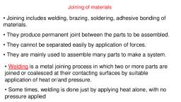
WELDING, – Welding is a materials jo ining process which produces coalescence, of materials by heating them to suitable temperatures with or, without the application of pressure or by the application of pressure, alone, and with or without the use of filler material., – Welding is used for making permanent joints., – It is used in the manufacture of automobile bodies, aircraft frames,, railway wagons, machine frames, structural works, tanks, furniture,, boilers, general repair work and ship building., , 5, , TYPES, • Plastic Welding or Pressure Welding, The piece of metal to be joined are heated to a, plastic state and forced together by external pressure, , (Ex) Resistance welding, • Fusion Welding or Non-Pressure Welding, The material at the joint is heated to a molten state and, allowed, to solidify, (Ex) Gas welding, Arc welding, , 6, , 3
Page 7 :
Classification of welding processes:, (i). Arc welding, •, Carbon arc, •, Metal arc, •, Metal inert gas, •, Tungsten inert gas, •, Plasma arc, •, Submerged arc, •Electro-slag (ii)., Gas Welding, •, Oxy-acetylene, •, Air-acetylene, •Oxy-hydrogen (iii)., Resistance Welding, •, Butt, •, Spot, •, Seam, •, Projection, •, Percussion, , (iv)Thermit Welding, (v)Solid State Welding, Friction, Ultrasonic, Diffusion, Explosive, (vi) Newer Welding, Electron-beam, Laser, (vii) Related Process, Oxy-acetylene cutting, Arc cutting, Hard facing, Brazing, Soldering, 7, , Arc welding, •, •, •, •, •, •, •, •, •, •, , Equipments:, A welding generator (D.C.) or Transformer (A.C.), Two cables- one for work and one for electrode, Electrode holder, Electrode, Protective shield, Gloves, Wire brush, Chipping hammer, Goggles, 8, , 4
Page 8 :
Power Source in Arc Welding, • Direct current (DC) vs. Alternating current (AC), – AC machines less expensive to purchase and operate, but, generally restricted to ferrous metals, – DC equipment can be used on all metals and is generally, noted for better arc control, , 9, , Arc Welding Equipments, , 10, , 5
Page 9 :
Arc Welding, , Uses an electric arc to coalesce, metals, Arc welding is the most common, method of welding metals, Electricity travels from electrode to, base metal to ground, , 11, , Fusion Welding: Arc Welding (AW), A fusion welding process in which coalescence of the metals is, achieved by the, heat from an electric arc between an electrode and the work, 1., , Electric energy from the arc produces temperatures ~ 10,000 F, (5500 C), hot enough to melt any metal., , 2., , Most AW processes add filler metal to increase volume and, strength of weld, joint., A pool of molten metal is formed near electrode tip, and as, electrode is moved along joint, molten weld pool solidifies in its, wake, , 3., , 12, , 6
Page 10 :
Arc and Power Source Characteristics in Arc Welding, , Arc Characteristics, , Power Source Characteristics, , 13, , Two Basic Types of Arc Welding, (Based on Electrodes), 1. Consumable electrodes, ❑ consumed during welding process, ❑ added to weld joint as filler metal, ❑ in the form of rods or spools of wire, , 2. Non-consumable electrodes, ❑ not consumed during welding process but does get gradually, eroded, ❑ filler metal must be added separately if it is added, 14, , 7
Page 11 :
Arc welding (AW): Arc Shielding, 1. At high temperatures in AW,metals are chemically reactive to, oxygen, nitrogen, and hydrogen in air, ❑ Mechanical properties of joint can be degraded by these, reactions, ❑ Arc must be shielded from surrounding air in AWprocesses, to prevent reaction, 2. Arc shielding is accomplished by, ❑ Shielding gases, e.g., argon, helium, CO2, ❑ Flux, 15, , Arc welding (AW): Flux, ❑ A substance that prevents formation of oxides and other, contaminants in welding, which comes from, 1. granules that are created from the welded material., 2. a coating on the stick electrode that melts during welding to, cover operation., 3. a core that is within tubular electrodes and is released as, electrode is consumed., ❑ Melts during welding to be liquid slag that hardens when, cooled. The slag should be removed for a clean look by, brushing or grinding off., , 16, , 8
Page 12 :
Oxyacetylene Welding (OAW), , The oxyacetylene welding process uses a, combination of oxygen and acetylene gas to, provide a high temperature flame., 19, , Oxyacetylene Welding (OAW), , • OAW is a manual process in which the, welder must personally control the the torch, movement and filler rod application, • The term oxyfuel gas welding outfit refers, to all the equipment needed to weld., • Cylinders contain oxygen and acetylene gas, at extremely high pressure., 20, , 10
Page 13 :
Typical Oxyacetylene Welding, (OAW) Station, , 21, , Oxygen Cylinders, • Oxygen is stored within cylinders of various, sizes and pressures ranging from 2000- 2640, PSI. (Pounds Per square inch), • Oxygen cylinders are forged from solid, armor plate steel. No part of the cylinder, may be less than 1/4” thick., • Cylinders are then tested to over 3,300 PSI, using a (NDE) hydrostatic pressure test., , 22, , 11
Page 14 :
Oxygen Cylinders, • Cylinders are regularly, re-tested using, hydrostatic (NDE), while in service, • Cylinders are regularly, chemically cleaned, and annealed to relieve, “jobsite” stresses, created by handling ., 23, , Oxygen Cylinders, • Oxygen cylinders, incorporate a thin metal, “pressure safety disk”, made from stainless steel, and are designed to, rupture prior to the, cylinder becoming, damaged by pressure., • The cylinder valve should, always be handled, carefully, 24, , 12
Page 15 :
Pressure Regulators for, Cylinders, • Reduce high storage, cylinder pressure to, lower working, pressure., • Most regulators have a, gauge for cylinder, pressure and working, pressure., 25, , Pressure Regulators for Cylinders, , • Regulators are shut off, when the adjusting screw, is turn out completely., • Regulators maintain a, constant torch pressure, although cylinder pressure, may vary, • Regulator diaphragms are, made of stainless steel, 26, , 13
Page 16 :
Pressure Regulators Gauges, Using a “Bourdon” movement, • Gas entering the gauge fills a, Bourdon tube, • As pressure in the semicircular, end increases it causes the free, end of the tube to move, outward., , • This movement is transmitted, through to a curved rack which, engages a pinion gear on the, pointer shaft ultimately, showing pressure., 27, , Regulator Hoses, • Hoses are are fabricated from, rubber, • Oxygen hoses are green in, color and have right hand, thread., • Acetylene hoses are red in, color with left hand thread., • Left hand threads can be, identified by a grove in the, body of the nut and it may, have “ACET” stamped on it, 28, , 14
Page 17 :
Check Valves & Flashback, Arrestors, • Check valves allow gas, flow in one direction only, • Flashback arrestors are, designed to eliminate the, possibility of an explosion, at the cylinder., • Combination Check/, Flashback Valves can be, placed at the torch or, regulator., 29, , Acetylene Gas, • Virtually all the acetylene distributed for welding and cutting use, is created by allowing calcium carbide (a man made product) to, react with water., , • The nice thing about the calcium carbide method of producing, acetylene is that it can be done on almost any scale desired., Placed in tightly-sealed cans, calcium carbide keeps indefinitely., For years, miners’ lamps produced acetylene by adding water, a, drop at a time, to lumps of carbide., • Before acetylene in cylinders became available in almost every, community of appreciable size produced their own gas from, calcium carbide., 30, , 15
Page 18 :
Acetylene Cylinders, • Acetylene is stored in cylinders specially designed, for this purpose only., • Acetylene is extremely unstable in its pure form at, pressure above 15 PSI (Pounds per Square Inch), • Acetone is also present within the cylinder to, stabilize the acetylene., • Acetylene cylinders should always be stored in the, upright position to prevent the acetone form, escaping thus causing the acetylene to become, unstable., 31, , Acetylene Cylinders, • Cylinders are filled with a, very porous substance, “monolithic filler” to help, prevent large pockets of, pure acetylene form, forming, • Cylinders have safety, (Fuse) plugs in the top and, bottom designed to melt at, 212° F (100 °C), 32, , 16
Page 19 :
Acetylene Valves, • Acetylene cylinder shut, off valves should only be, opened 1/4 to 1/2 turn, • This will allow the, cylinder to be closed, quickly in case of fire., • Cylinder valve wrenches, should be left in place on, cylinders that do not, have a hand wheel., 33, , Oxygen and Acetylene Regulator, Pressure Settings, • Regulator pressure may vary with different, torch styles and tip sizes., • PSI (pounds per square inch) is sometimes shown as, PSIG (pounds per square inch -gauge), • Common gauge settings for cutting, – 1/4” material Oxy 30-35psi Acet 3-9 psi, – 1/2” material Oxy 55-85psi Acet 6-12 psi, – 1” material Oxy 110-160psi Acet 7-15 psi, , • Check the torch manufactures data for, optimum pressure settings 34, , 17
Page 20 :
Types of Flame, • There are three distinct types of oxy-acetylene, flames, usually termed:, – Neutral, – Carburizing (or “excess acetylene”), – Oxidizing (or “excess oxygen” ), • The type of flame produced depends upon the, ratio of oxygen to acetylene in the gas mixture, which leaves the torch tip., 35, , FLAME Settings, •, , •, , Oxygen is turned on, flame immediately changes into a long white inner, area (Feather) surrounded by a transparent blue envelope is called, Carburizing flame (30000 c), Addition of little more oxygen give a bright whitish cone surrounded by the, transparent blue envelope is called Neutral flame (It has a balance of fuel, gas and oxygen) (32000 c), , •, •, , Used for welding steels, aluminium, copper and cast iron, If more oxygen is added, the cone becomes darker and more pointed, while, the envelope becomes shorter and more fierce is called Oxidizing flame, , •, , Has the highest temperature about 34000 c, , •, , Used for welding brass and brazing operation, , 36, , 18
Page 21 :
Pure Acetylene and Carburizing, Flame profiles, , 37, , Neutral and Oxidizing Flame, Profiles, , 38, , 19
Page 22 :
Three basic types of oxyacetylene flames used in oxyfuel-gas welding and cutting, operations: (a) neutral flame; (b) oxidizing flame; (c) carburizing, or reducing flame., , 39, , •Three basic types of oxyacetylene flames used in, , oxyfuel-gas welding and cutting operations:, •(a) neutral flame; (b) oxidizing flame; (c), carburizing, or reducing flame., 40, , 20
Page 23 :
Chapter 3, , Gas Cutting, 41, , GAS CUTTING, • Ferrous metal is heated in to red hot condition and a jet of pure, oxygen is projected onto the surface,which rapidly oxidizes, • Oxides having lower melting point than the metal, melt and are, blown away by the force of the jet, to make a cut, • Fast and efficient method of cutting steel to a high degree of, accuracy, • Torch is different from welding, • Cutting torch has preheat orifice and one central orifice for oxygen, jet, • PIERCINGand GOUGINGare two important operations, • Piercing, used to cut a hole at the centre of the plate or away from, the edge of the plate, • Gouging,to cut a groove into the steel surface, 42, , 21
Page 24 :
Flame Cutting, , • Metal is merely melted by the, flame of the oxyfuel gas torch, and blown away to form a gap or, kerf., • When ferrous metal is cut,, actually burning of iron takes, place according to one or more, of the following reactions, Fe+ O, Feo+ Q, 3Fe+2 O2 Fe3 O4 + Q, 4Fe+3 O2, 2Fe2 O3 + Q, 43, , • Because, these reactions cannot take place below 815°C o xyfuel flame is first, used to raise the metal temperature where burning can be initiated. Then a stream, of pure o xygen is added to the torch (or the oxygen content of the oxyfuel, mixture is increased) to oxidize the iron. The liquid iron and iron oxides are then, expelled from the joint by the kinetic energy of the oxygen gas stream., • Low rate of heat input, and need of preheating ahead of the cut, oxyfuel produces, a relatively large heat affected zone and thus associated distortion zone., • The process is suitable when edge finish or tolerance is not critical., • Theoretically heat generated due to burning of Fe is sufficient to continue cutting, however due to losses additional heat supply is needed. If the work is already hot, due from the other processes, supply of oxygen through a small diameter pipe is, needed to continue cut. This is called Oxygen Lance Cutting. A work piece, temperature of 1200°C is needed to sustain the cutting., • Low carbon steel from 5 to 75 mm can be cut., , 44, , 22
Page 25 :
GAS CUTTING…, , Manual Gas Cutting, , 45, , Weld joints, , 46, , 23
Page 26 :
SOLID / LIQUID STATE BONDING, • Low temperature joining methods are used when the metal to, be joined cannot withstand high temperature, or intricate, sections are to be joined, or dissimilar metals are to be joined,, or weldability of material is poor., • In these methods, the gap between the metal pieces to be, joined is filled with molten filler material after heating the, base metal. Melting point of filler material is much lower than, base metals., , • The bonding is not due to melting of parent metal and fusio, , •, , 47, , • Filler material is drawn into the gap between the metal pieces, to be joined by capillary action and the bond formation is, initiated when the molten filer metal comes under intimate, contact with the solid surface as in solid state welding., • The nature of bond formed is much complex here, and, invariably there is some degree of intersolubility between filler, and base metals., • This inter-diffusion at the base metal surface and resulting, alloy has a strength which is very close to that the base metal., 48, , 24
Page 27 :
• For a good joint strength the liquid filler, metal; must flow into the gap between, the metal pieces to be joined and cover, the entire surface area, without gaps or, blow holes. The following usually, insures good bonding:, – Clean base metal surfaces, – Maintain optimum gap, –Heat the joining area above melting, temperature of the filler material, –Use fluxes for welding of base metal, surfaces., • Joint strength is sensitive to the gap and, there exists an optimum gap for a filler, material., , 49, , 50, , 25
Page 28 :
Chapter 4, , Arc Welding, 51, , Consumable Electrode AWProcesses, ❑ Shielded Metal Arc Welding (or Stick Welding), , ❑ Gas Metal Arc Welding (or Metal Inert Gas Welding), ❑ Flux-Cored Arc Welding, ❑ Electro-gas Welding, ❑ Submerged Arc Welding, , 52, , 26
Page 29 :
AW: Consumable: Shielded Metal Arc Welding, (SMAW), ❑, , Uses a consumable electrode consisting of a filler metal rod and coating, around rod., , ❑, , Coating composed of chemicals that provide flux and shielding., , ❑ Low cost welding system: Power supply, connecting cables, and electrode, holder available for $300 to $400., , 53, , SMAWApplications, , ❑ Used for steels, stainless steels, cast irons, and certain, nonferrous alloys., ❑ Not used or rarely used aluminum and its alloys, copper, alloys, and titanium., ❑ Can be used in windy weather., ❑ Can be used on dirty metals (i.e. painted or rusted surfaces)., ❑ Good for repair work., ❑ Makes thick welds., , 54, , 27
Page 30 :
AR: Consumable: Gas Metal Arc Welding (GMAW), Metal Inert Gas (MIG) Welding, Uses a consumable bare metal wire as electrode with shielding by, flooding arc with a gas, 1. Wire is fed continuously and automatically from a spool, through the welding gun., 2. Shielding gases include argon and helium for aluminum, welding, and CO2 for steel welding., 3. Bare electrode wire (no flux) plus shielding gases eliminate, slag on weld bead. No need for manual grinding and cleaning, of slag, 4. Medium cost welding system: $1000 to $1200, 55, , Gas Metal Arc Welding, , 56, , 28
Page 31 :
GMAW Advantages over SMAW, 1. Continuous welding because of continuous wire electrode., , Sticks must be periodically changed in SMAW., 2. Higher deposition rates., 3. Eliminates problem of slag removal., , 4. Can be readily automated., 5. Has better control to make cleaner & narrower welds than, SMAW., , 57, , GMAWApplications, , 1. Used to weld ferrous and various non-ferrous and metals., 2. Good for fabrications such as frames and farm equipment., , 3. Can weld thicker metal (not as thick as SMAW)., 4. Metal must be clean to start weld., , 58, , 29
Page 32 :
Non-consumable Electrode Processes, ❑ Gas Tungsten Arc Welding, ❑ Plasma Arc Welding, ❑ Carbon Arc Welding, , ❑ Stud Welding, , 59, , AW: non-consumable: Gas Tungsten Arc Welding, (GTAW) or Tungsten Inert Gas (TIG) Welding, Uses a non-consumable tungsten electrode and an inert gas for arc, shielding, 1. Melting point of tungsten = 3410C (6170F)., 2. Used with or without a filler metal. When filler metal used, it is, added to weld pool from separate rod or wire., , 3. Applications: aluminum and stainless steel mostly., 4. High cost for welding system: $4000., 60, , 30
Page 33 :
Gas Tungsten Arc Welding, , Filler rod, , 61, , Advantages and Disadvantages of GTAW, , Advantages:, 1. High quality welds for suitable applications, - Welds are cleaner and narrower than MIG, 2. No spatter because no filler metal through arc, 3.Little or no post-weld cleaning because no flux, Disadvantages:, , 1. More difficult to use than MIG welding, 2. More costly than MIG welding, , 62, , 31
Page 34 :
GTAWApplications, 1. Used to weld ferrous and various non-ferrous and metals., 2. Can weld various dissimilar metals together., 3. Good for fabrications such as aircraft or race car frames., , 4. Used for welding thinner metal parts (not as thick as MIG)., 5. Metal must be very clean to start weld., , 63, , Plasma Arc Welding, , 64, , 32
Page 35 :
Advantages and Disadvantages of PAW, Advantages:, • Good arc stability and excellent weld quality, • Better penetration control than other AWprocesses, • High travel speeds, •Can be used to weld almost any metals, Disadvantages:, • High equipment cost, • Larger torch size than other AWprocesses, – Tends to restrict access in some joints, , 65, , THANKS, , 66, , 33
Page 36 :
Chapter 5, , Brazing and, Soldering, 67, , Brazing and Soldering, • Brazing, It is a low temperature joining process. It is performed at, temperatures above 840º F and it generally affords strengths, comparable to those of the metal which it joins. It is low, temperature in that it is done below the melting point of the base, metal. It is achieved by diffusion without fusion (melting) of the, base, , Brazing can be classified as:, Torch brazing, Dip brazing, Furnace brazing, Induction brazing, , 68, , 34
Page 37 :
BRAZING, , Brazing methods, (a) Torch and filler rods, (b)Ring of filler metal at, entrance of Gap, (c)Foil of filler metal, between flat part surfaces, , 69, , • In brazing the joint is made by heating the base, metal red hot and filling the gap with molten, metal whose melting temperature is typically, above 450°C but below melting temperature o, base metal. The filler metals are generally, copper alloys. Cu-Zn and Cu-Ag alloys are, used for brazing because they form alloy with, iron and have good strength., 70, , 35
Page 38 :
VARIOUS BRAZING JOINTS, , (a) Conventional butt, (b) Scarf joint, (c) Stepped joint, (d) Increased crossest ion, (a) Conventional Lap, (b) Cylindrical part, (c) Sandwiched part, (d) Use of sleeve, , 71, , Brazing, , 72, , Prof MA Saloda, , 36
Page 39 :
Advantages & Disadvantages, Advantages, •, •, •, •, , Dissimilar metals which can not be welded can be joined by brazing, Very thin metals can be joined, Metals with different thickness can be joined easily, In brazing thermal stresses are not produced in the work piece., Hence there is no distortion, • Using this process,carbides tips are brazed on the steel tool holders, , Disadvantages, • Brazedjoints have lesser strength compared to welding, • Joint preparation cost is more, • Can be used for thin sheet metal sections, , 73, , SOLDERING, • Soldering is very similar to brazing except that filler material, is usually a lead-tin based alloy which has much lower, strength and melting temperature around 250°C., , • In this process less alloying action between base metal and, filler material as compared to brazing takes place hence the, strength of joint is lesser., •, , It is carried out using electrical resistance heating, , 74, , 37
Page 40 :
Soldering, • It is a low temperature joining, process. It is performed at, temperatures below 840ºF for, joining., • Soldering is used for,, • Sealing, as in automotive, radiators or tin cans, • Electrical Connections, • Joining thermally, sensitive components, • Joining dissimilar metals, , 75, , THANKS, , 76, , 38
Page 41 :
Chapter 6, , Resistance, Welding, 77, , Resistance Welding (RW), Agroup of fusion welding processes that use a combination of, heat and pressure to accomplish coalescence, • Heat generated by electrical resistance to current flow at, junction to be welded, • Principal RW process is resistance spot welding (RSW), , 78, , 39
Page 42 :
Resistance Welding, , • Resistance, welding,, showing components in, spot welding, the main, process in the RW, group, , 79, , Components in Resistance Spot Welding, • Parts to be welded (usually sheet metal), • Two opposing electrodes, • Means of applying pressure to squeeze parts between, electrodes, • Power supply from which a controlled current can be applied, for a specified time duration, , 80, , 40
Page 43 :
Resistance Spot Welding (RSW), , Resistance welding process in which fusion of faying surfaces of, a lap joint is achieved at one location by opposing electrodes, • Used to join sheet metal parts, • Widely used in mass production of automobiles, metal, furniture, appliances, and other sheet metal products, – Typical car body has ~ 10,000 spot welds, – Annual production of automobiles in the world is, measured in tens of millions of units, , 81, , Spot Welding Cycle, , • (a) Spot welding cycle, • (b) Plot of force and, current, • Cycle:, (1), parts, inserted, between, electrodes,, (2), electrodes close, (3), current on, (4) current, off, (5) electrodes, opened, , 82, , 41
Page 44 :
Advantages and Drawbacks of Resistance Welding, Advantages:, • No filler metal required, • High production rates possible, • Lends itself to mechanization and automation, • Lower operator skill level than for arc welding, • Good repeatability and reliability, Disadvantages:, • High initial equipment cost, • Limited to lap joints for most RW processes, , 83, , Resistance Seam Welding (RSEW), , Uses rotating wheel electrodes to produce a series of, overlapping spot welds along lap joint Can produce airtight joints., Applications:, – Gasoline tanks, – Automobile mufflers, , – Various sheet metal containers, , 84, , 42
Page 45 :
Resistance Seam Welding, , 85, , Resistance Projection Welding (RPW), Aresistance welding process in which coalescence occurs at one, or more small contact points on the parts, • Contact points determined by design of parts to be joined, • May consist of projections, embossments, or localized, intersections of parts, , 86, , 43
Page 46 :
Resistance ProjectionWelding, , (1) Start of operation, contact between parts is at projections;, (2)when current is applied, weld nuggets similar to spot welding, are formed at the projections, , 87, , Other Resistance Projection Welding Operations, • (a) Welding of fastener on sheet metal and (b) cross-wire, welding, , 88, , 44
Page 47 :
Arc welding, Advantages, – Most efficient way to join, metals, – Lowest-cost joining, method, – Affords lighter weight, through better utilization, of materials, – Joins all commercial, metals, – Provides design flexibility, , Limitations, • Manually applied, therefore, high labor cost., • Need high energycausing, danger, • Not convenient for, disassembly., • Defects are hard to detect at, joints., , 89, , Comparison of A.C. and D.C. arc welding, Alternating Current (from Transformer), More efficiency, Power consumption less, Cost of equipment is less, , Higher voltage – hence not safe, Not suitable for welding non ferrous metals, Not preferred for welding thin sections, Any terminal can be connected to the work or electrode, , 90, , 45
Page 48 :
Direct Current (from Generator), Less efficiency, Power consumption more, Cost of equipment is more, Low voltage – safer operation, suitable for both ferrous non ferrous metals, preferred for welding thin sections, Positive terminal connected to the work, Negative terminal connected to the, , electrode, 91, , Electric arc welding --Polarity, SMAW - DC Polarity, Reverse Polarity, , Straight Polarity, , (–), (+), Shallow penetration, (thin metal), , (+), (–), Deeper w eld penetration, , AC- Gives pulsing arc, - used for w elding thick, sectionssection, 92, , 46
Page 49 :
Chapter 7, , Submerged, Arc Welding, 93, , INTRODUCTION, ➢, , In submerged-arc welding (SAW), the weld arc is shielded by a, granular flux consisting of lime, silica, manganese oxide,, calcium fluoride, and other compounds., , ➢, , The flux is fed into the weld zone from a hopper by gravity flow, through a nozzle., , ➢, , The thick layer of flux completely covers the molten metal., , ➢, , It prevents spatter and sparks and suppresses the intense, ultraviolet radiation and fumes characteristic of the SMAW, process., , 94, , 47
Page 50 :
Schematic illustration of the submerged-arc welding proces s and equipment, , 95, , ➢ The flux acts as a thermal insulator by promoting deep penetration, , of heat into the workpiece., ➢ The consumable electrode is fed automatically through a tube called, , welding gun., ➢ Electrical currents range between 300 & 2000 A., ➢ Because the flux is gravity fed, the SAW process is limited largely to, , welds in a flat or horizontal position., ➢ Circular welds can be made on pipes and cylinder by rotating the, , workpiece., ➢ The process is automated and is used to weld variety of carbon and, , alloy steel and stainless-steel sheets or plates at speeds as high as, 5 m/min., ➢ Weld quality is very high – good toughness, ductility and uniformity, of properties., ➢ SAW process provides very high welding productivity, depos iting 4, , to 10 times the amount of weld metal per hour as the SMAW, process., ➢ Suitable for thick-plate welding for shipbuilding and pressure, vessels., , 96, , 48
Page 51 :
Advantages of SAW, -, , -, , High deposition rates (over 100 lb/h (45 kg/h) have been reported);, High operating factors in mechanized applications;, Deep weld penetration;, Sound welds are readily made (with good process design and, control);, High speed welding of thin sheet steels at over 100 in/min (2.5, m/min) is possible;, Minimal welding fume or arc light is emitted., , Limitations of SAW, , - Limited to ferrous (steel or stainless steels) and some nickel based, alloys;, - Normally limited to the 1F, 1G, and 2F positions;, - Normally limited to long straight seams or rotated pipes or vessels;, - Requires relatively troublesome flux handling systems;, - Flux and slag residue can present a health & safety issue;, 97, , THANKS, , 98, , 49
Page 52 :
Chapter 8, , Solid State, Welding, 99, , Solid state welding processes, , Friction Welding, Ultrasonic Welding, , Diffusion Welding, , Resistance Welding, , 100, , 50
Page 53 :
Inertia Welding, • One part rotated, one stationary, •Stationary part forced against, rotating part, •Friction converts kinetic energy to, thermal energy, •When sufficiently hot, rotation, is stopped & axial force, increased, •Metal at interface melts and is, joined, , 101, , Friction Welding (FRW), SSW process in which coalescence is achieved by frictional heat, combined with pressure, • When properly carried out, no melting occurs at faying, surfaces, • No filler metal, flux, or shielding gases normally used, • Process yields a narrow HAZ, • Can be used to join dissimilar metals, • Widely used commercial process, amenable to automation and, mass production, 102, , 51
Page 54 :
FrictionWelding, • (1) Rotating part, no contact; (2) parts brought into contact to, generate friction heat; (3) rotation stopped and axial pressure, applied; and (4) weld created, , 103, , Applications and Limitations of FrictionWelding, Applications:, • Shafts and tubular parts, • Industries: automotive, aircraft, farm equipment, petroleum, and natural gas, Limitations:, • At least one of the parts must be rotational, • Flash must usually be removed (extra operation), • Upsetting reduces the part lengths (which must be taken into, consideration in product design), , 104, , 52
Page 55 :
Diffusion Welding, , •Parts forced together at high temperature, , (< 0.5Tm absolute) and pressure, • Heated in furnace or by resistance heating, • Atoms diffuse across interface, • Good for dissimilar metals, •After sufficient time the interface disappears, •Bond can be weakened by surface, impurities, , 105, , THANKS, , 106, , 53
Page 56 :
Chapter 9, , Thermit, Welding &, Other Welding, 107, , THERMIT WELDING (TW), , •, •, •, •, , FW process in which heat for coalescence is produced by, superheated molten metal from the chemical reaction of, thermite, Thermite = mixture of Al and Fe3 O4 fine powders that produce, an exothermic reaction when ignited, Also used for incendiary bombs, Filler metal obtained from liquid metal, Process used for joining, but has more in common with casting, than welding, , 108, , 54
Page 57 :
Thermit Welding, , • (1) Thermit ignited; (2) crucible tapped, superheated metal, flows into mold; (3) metal solidifies to produce weld joint, , 109, , TW Applications, • Joining of railroad rails, • Repair of cracks in large steel castings and forgings, • Weld surface is often smooth enough that no finishing is, required, , 110, , 55
Page 58 :
WELDING METALLURGY, • In fusion welded joint, where three distinct zones can be, identified:• The base metal, • The heat affected Zone, • The fusion Zone, , 111, , Two major concerns occur in the heat affected zone which, effect weldability these are, a.) changes in structure as a result, of the thermal cycle experienced by the passage of the weld, and the resulting changes in mechanical properties coincident, with these structural changes, and b.) the occurrence of cold or, delayed cracking due to the absorption of hydrogen during, welding., , 112, , 56
Page 59 :
Heat Affected Zone, •, , •, , The Heat-Affected Zone (HAZ) is an area of a base metal which, while, not melted, still has had its chemical properties altered by high temperature, heat. This phenomenon primarily occurs during welding or high-heat, cutting. The high temperature fro m the welding process and eventual recooling causes this change from the weld interface to the end of the, sensitizing temperature in the metal. These areas can be varying sizes and, levels of severity., The metallurgical changes that can occur at the HAZ tend to cause stresses, that reduce the strength of the material. The HAZ can also suffer fro m a, decreased resistance to corrosion and/or cracking (i.e, sensitization). These, metallurgical changes can also lead to the formation of nitrides at the HAZ,, which can affect weldability. In addition, the microstructure at the HAZ can, be altered in a way that increases its hardness compared to the surrounding, material. Hardness, sensitization, and high local stresses in or near the HAZ, may be mitigated by practices such as controlled pre- and post-weld heat, treatment and solution annealing., , 113, , How much these changes in metallurgical and physical, properties can affect the HAZ of the material is dependent, on a number of factors, including the base material, the, weld filter metal, and the amount and concentration of heat, input during the welding process., , 114, , 57
Page 60 :
115, , Hardfacing, Hard facing is a metalworking process where harder or tougher, material is applied to a base metal. It is welded to the base, material, and generally takes the form of specialized electrodes, for arc welding or filler rod for oxyacetylene and TIG welding., Powder metal alloys are used in (PTA) also called Powder plasma, welding system and Thermal spray processes like HVOF, Plasma, spray, Spray and Fuse, etc., , 116, , 58
Page 61 :
• Hard facing may be applied to a new part during production to, increase its wear resistance ,or it may be used to restore a worndown surface. Hard facing by arc welding is a surfacing operation, to extend the service life of industrial components, pre-emptively, on new components, or as part of a maintenance program. The, result of significant savings in machine down time and production, costs has meant that this process has been adopted across many, industries such as Steel, Cement, Mining, Petro chemical, Power,, Sugar cane and Food. According to the results of an experimental, study, the SMAW (Shielded Metal Arc Welding) and the GMAW, (Gas Metal Arc Welding)hard facing processes were effective in, reducing the wear on the mould board ploughshare. With the, SMAW and GMAW hard facing processes, the life span of the, ploughshare was increased approximately 2 times., 117, , Cladding, Cladding is the bonding together of dissimilar metals. It is, different from fusion welding or gluing as a method to fasten the, metals together. Cladding is often achieved by extruding two, metals through a die as well as pressing or rolling sheets together, under high pressure., , 118, , 59
Page 62 :
Microstructure Welding, , The microstructural studies of friction welding helps in, understanding microstructural changes occurred during, friction welding process. High temperature and strain during, friction welding process changes the microstructure of the, parent material., , 119, , Welding Symbols, Representationof welds on drawings requires the use of following, elements1. A basic symbol to specify each type of weld., 2. A reference line and an arrow to indicate the location the weld in a, joint., 3. Supplementary symbols to mark weld-all-round, finish of welds, etc., 4. Weld dimensions in cross-section and in length., , 120, Salo, , 60
Page 63 :
Basic Weld Symbols, FILLET, , SQUARE BUTT, , SINGLE V-BUTT, , AND MANY MORE SYMBOLS….., , 121, , WELDING DESIGN, Before an arc can be struck on metal, the product must be designed to serve its, purpose, the material chosen and the method of welding determined in more or, less detail., The weldment design engineer must, I., Know the limitations and specific requirements of the processes as well, as the equipment available on the shop floor., , II., , Have a good working knowledge of the shop problems of shrinkage and, distortion., , III. Have accurate knowledge not only of suitability but also of availability of, materials or the costs of extras., IV. Be able to calculate stresses, strengths and determine weld sizes and put, these together to work out a design that meets all service requirements., , 12, 2, , 61
Page 64 :
Welding Joint Design, Since, welding joins metals, design for welding is chiefly concerned with, joints-when to use a joint, how to weld it, where to place it, what to do and, what not to do., Selection and preparation of weld joints is an important step in the fabrication, of a weldment., , Selection of correct joint design is very essential if welded members are to, perform within the load service, corrosive atmosphere and safety requirements., , 12, 3, , Welding, , Summary, , Fusion Welding (FW), Solid StateWelding (SSW), Oxyfuel welding, , Arc wel ding, , Shi elding, Fl ux, , Cons umable electrodes, , Non-consumable electrodes, , Va rious welding processes (AW) are developed to address the two issues: s hielding a nd fl ux, , 12, 4, , 62
Page 65 :
Chapter 10, , Welding, Defects, 12, 5, , Types of defects, Slag Inclusion, Undercut, Porosity, Incomplete fusion, Overlap, Underfill, Spatter, Excessive Convexity, Incomplete Penetration, Excessive Penetration, , 12, 6, , 63
Page 66 :
Slag Inclusion, Slag is the waste material created and bits of this solid material can, become incorporated into wel d. Bits of flux and rust can be counted, as slag., , Cause:- Low amperage, improper techniques, slow travel rate, Prevention:- Increase amperage, increase travel rate, Repair:- Remove by grinding or other mechanical process, , 12, Salod, , UNDERCUT, Undercutting is an extremely common welding defect. It happens when, your base metal is burned away at one of the toes of a weld. portion of, base metal melted away, Cause:- High amperage, wrong electrode angle, long arc length,, electrode is too large for the base metal, Prevention:- clean metal before welding, Repair:- Weld with smaller electrode, sometimes must be low hydrogen, with preheat., , 12, 8, , 64
Page 67 :
POROSITY, In this defect, air bubbles or gases are present in the weld zone, Cause:- inclusion of atmospheric gases, sulfur in weld metal, or surface, contaminants, , Prevention:- slower speed to allow gases time to escape, , 12, 9, , INCOMPLETE FUSION, A weld bead in which fusion has not occurred throughout entire cross, section of joint, , Cause:- Low amperage, fast travel speed, short arc gap, lack of preheat,, electrode too small, unclean base metal, Prevention:- Eliminate the potential causes, Repair:- Remove & reweld, being careful to completely remove the, defective area., , 13, 0, , 65
Page 68 :
Cracks, It is a discontinuity in the metal that significantly reduces strength, Cause:- low ductility of weld, solidification shrinkage, , Prevention:When finishing move back the electrode to fill up the crack, Increase, crater fill time by power source., , 13, 1, , OVERLAP, Weld metal spills beyond joint onto part surface but no fusion occurs, , Cause:- Improper welding technique, steep electrode angle, fast travel, speed, Prevention:- Overlap is a contour problem. Proper welding technique, will prevent this problem, , 13, 2, , 66
Page 69 :
UNDERFILL, Depression in weld below adjacent base metal surface, Cause:- Improper welding techniques, , Prevention:- Apply proper welding techniques for the weld type &, position. Use stripper beads before the cover pass., Repair:- Simply weld to fill. May require preparation by grinding., , 13, 3, , SPATTER, Small particles of metal that attach themselves to the surface of the, material, Cause:- High arc power, Damp electrodes, , Prevention:- Reduce arc power, reduce arc length, use dry electrodes, Repair:- Remove by mechanical process, , 13, 4, , 67
Page 70 :
INCOMPLETE PENETRATION, Incomplete penetration happens when your filler metal and base metal, aren’t joined properly, and the result is a gap or a crack of some sort., Cause:- Low amperage, low preheat, tight root opening, fast travel speed,, short arc length, Prevention:- Correct the contributing factors., Repair:- Back gauge and back weld, , 13, 5, , EXCESSIVE PENETRATION, , 13, 6, , 68
Page 71 :
EXCESSIVE CONVEXITY, Cause:- Amperage & travel speed, Prevention:- Observe proper parameters & techniques, , Repair:- Must blend smoothly into the base metal, , 13, 7, , EXCESSIVE CONCAVITY, Cause:- Amperage & travel speed, Prevention:- Observe proper parameters & techniques, Repair:- Must blend smoothly into the base metal, , 13, 8, , 69
Page 72 :
Arc blow, Arc deflection as a result of magnetic effects into the opposite direction of, the earth lead clamp., Arc deflection as a result of magnetic effects in the direction of heavy part of, work piece especially at corner and edges., Remedies:, Use AC electrode where possible., Try welding away from earth clamp connection. Try splitting the earth clamp, and correct to both side of the joint., , 13, 9, , Fusion Weld Zone, , 14, 0, , 70
Page 73 :
Weldability, • Capacity of a metal or combination of metals to be welded into a, suitable structure, and for the resulting weld joint(s) to possess, the required metallurgical properties to perform satisfactorily in, intended service, • Good weldabilitycharacterized by:, , • Absence of weld defects, • Strength, ductility, and toughness in welded joint, , 14, 1, , Inspection and TestingMethods, • Visual inspection, • Nondestructive evaluation, • Destructive testing, , 14, 2, , 71
Page 74 :
Visual Inspection, • Most widely used welding inspection method, • Human inspector visuallyexaminesfor:, , • Cracks, cavities, incomplete fusion, and other surface, defects, • Limitations:, , • Only surface defects are detectable, • Welding inspector must also decide if additional tests, are warranted, , 14, 3, , Nondestructive Evaluation (NDE)Tests, • Ultrasonic testing - high frequency sound waves through, specimento detect cracks and inclusions, • Radiographic testing - x-rays or gamma radiation provide, photograph of internal flaws, • Dye-penetrant and fluorescent-penetrant tests - to detect small, cracks and cavities at part surface, • Magnetic particle testing – iron filings sprinkled on surface reveal, subsurface defectsby distorting magnetic field in part, , 14, 4, , 72
Page 75 :
Destructive Testing, Tests in which weld is destroyed either during testing or to prepare, test specimen, • Mechanical tests - purpose is similar to conventional testing, methods suchas tensile tests, shear tests, etc, • Metallurgical tests - preparation of metallurgical specimens (e.g.,, photomicrographs) of weldment to examine metallic structure,, defects, extent and condition of heat affected zone, and similar, phenomena, , 14, 5, , Mechanical Tests in Welding, •, •, •, •, , Tension-shear test (a), Filletbreak test (b), Tension-shear of spot weld (c), Peel test for spot weld(d), , 14, 6, , 73
Page 76 :
References, • S.K. Hajra Choudhury and A.K. Hajra Choudhury: Elements of, Workshop Technology, Vol. I, Media Promoters & Publishers, Pvt. Ltd., Bombay., • JS Campbell: Principles of Manufacturing Materials and, Processes, TMH, • Richard L. Little: Welding and Welding Technology, TMH Co., Ltd., New Delhi., • R. K. Purohit: Mechanical Engineering, Scientific Publishers,, Jodhpur, • O.P. Khanna and M. Lal, Production Technology, , 147, , 74