Page 1 :
LCD LED T.V Panels Modification, and Major Repairs, , ImagineX ElectronicS
Page 2 :
1|Pag e, , M, Myy SSppeecciiaall R, Reeqquueesstt::, Please cannot give this E-book away for free and you do not have the, rights to redistribute this E-book anywhere on web., Copyright @ All Rights Reserved, Disclaimer And/ Or Legal Notices, The reader is expressly warned to consider and adopt all safety precaution that might be indicated by the activities herein and to avoid all potential hazards. This E-Book is for INFORMA-, , TIONAL PURPOSES only and the author do not accept any responsibilities or liabilities resulting from the use of this information. While every attempt has been made to verify the infor-, , mation provided here, the author cannot assume any responsibility for any loss, injury, errors,, , inaccuracies, omissions or inconvenience sustained by anyone resulting from this information., Most of the repair tips and solution given should only be carried out by suitable qualified electronics engineers/technicians. Please be careful as all electrical equipment is potentially dangerous when dismantled. Any perceived slights of policy, specific people or organizations are, unintentional., , Limit of Liability/ Disclaimer of Warranty, The author Imran Ashraf and publisher of this E-book and the accompanying materials have,, , Complied from various sources and also own knowledge of repair filed and his best efforts in, , preparing this book. The authors and publisher make no representation or warranties with, respect to the accuracy, applicability, fitness, or completeness of the contents of this Book., , They disclaim any warranties (expressed or implied), merchantability, or fitness for any particular purpose. The reader is expressly warned to consider and adapt all Safety precautions, , that might be indicated by the activities here in and to avoid all potential hazards. By following, the instructions contained herein, the reader willingly assumes all risks in connection with, such instructions. The authors and publisher shall in no event be held liable for any loss or, , other damages, including but not limited to special, incidental, consequential, or other damages. As always, the advice of a competent legal, tax, accounting or other professional should be, 1, , ImagineX ElectronicS
Page 3 : 2|Pag e, , sought. No this parts of this E-book/Guide/Manual shall be reproduced or transmitted by any, , means, electronic, mechanical, photocopying, printing and recording or otherwise . Any unau-, , thorized use of this material is prohibited. All product illustration, product names and logo are, trademark of their respective manufacturers. If you have any information regarding the ille-, , gal reselling or duplication of the E-book, please report it to
[email protected] for your, reward., , Dedication, , This E-book Dedicate to my late father Muhammad Ashraf, my Sweet, family and my Friends around the globe and My Pakistani friend, Naseeb Jan, they all helps me and support me a lot for preparation, this great e-book, Thanks all of you., , 2, , ImagineX ElectronicS
Page 4 :
3|Pag e, , LCD LED Panel Failure and Cure, COLLECTION OF TRICKS & HOW-LED LCD TV SERVICE FROM, VARIOUS SOURCES RELIABLE TECHNICIANs, , Here is I reveal a big secrete of Panel repairing for you and a Chance to earn big money, from it, Some LCD panel failures could possibly mistake for T-Con board issues. Other, than damage to the LCD glass, most panel failures are isolated to a particular area of the, screen. Since the T-Con disperses the pixel data to groups of line and column drive IC’s, situated on the outer edges of the panel, it is unlikely that more than one of these IC’s, would fail at the same time. Multiple columns of struck on or stuck off pixels are therefore, more likely to be the fault of the T-Con circuits. The same applies to a single row, of lit or unlit pixels. The T-Con simply cannot cut out a single line of information., , L.C.D L.E.D T.V Panels Connection and Voltages Understanding, , Here we talking about the main voltages and pin connection of L.C.D and L.E.D T.Vs, Panels, every technician should know where to test and how to check voltages of each, connection as they mention in Service Manual or schematic diagram or at least you, should know the basic working voltages., Connection Name, 1. VGL in, 2. VCL in, 3. VSS, 4. VDD, 5. VGH, 6. STV, , 7. CPV1, , 3, , Connection Working, Driver negative P.supply1, Driver negative p.supply2, Digital ground, , Voltages, Around -10.5v, Around -10v to -12v, GND, , Supply LCM driver output, , Around 12v+ to 19.5v+, Pulse, , VDD is the logic supply input for, the scan driver., Vertical Sync Input. The rising, edge of STV begins a frame of, data. The STV input is used to, generate the high-voltage STVP, output., Vertical Clock-Pulse Input. CPV1, controls the timing of the CKV1, and CKVB1 outputs, which, change state (by first sharing, charge) on its falling edge., , ImagineX ElectronicS, , Pulse
Page 6 :
5|Pag e, , low and is connected to VON when STV is high and CPV1 is low. When both STV, and CPV1 are high, STVP is high impedance., DLY Startup Delay Setting. Connect a capacitor to adjust the delay, DISH VOFF Discharge Connection. Pulling DISH below ground activates an internal connection between VOFF and GND, rapidly discharging the VOFF supply. Typically, DISH is capacitive connected to VDD, so that when VDD falls, VOFF is discharged., VCOM Operational Amplifier Output, , CKV High-Voltage, Gate-Pulse Output. When enabled, CKV toggles between its, high state (connected to GON) and its low state (connected to GOFF) on each falling edge of the CPV input. Further, CKV is high impedance whenever CPV and OE, are both low and whenever CPV is low and OECON is high., CKVCSCKV Charge-Sharing Connection. CKVCS connects to CKV whenever CKV is, high impedance to allow connection to CKVB, sharing charge between the capacitive loads on these two outputs., CKVBCS, CKVB Charge-Sharing Connection. CKVBCS connects to CKVB whenever CKVB is high impedance to allow connection to CKV, sharing charge between, the capacitive loads on these two outputs., CKVB High-Voltage, Gate-Pulse Output. CKVB is the inverse of CKV during active, states and is high impedance whenever CKV is high impedance., STVP High-Voltage, Start-Pulse Output. STVP is low (connected to GOFF) whenever STV is low and is high (connected to GON) only when STV is high and CPV and, OE are both low. When STV is high and either CPV or OE is high, STVP is high impedance., STV Vertical Sync Input. The rising edge of STV begins a frame of data. The STV, input is used to generate the high-voltage STVP output., OECON, Active-Low, Output-Enable Timing Input. OECON is driven by an RCfiltered version of the OE input signal. If OE remains high long enough for the resistor to charge the capacitor up to the OECON threshold, the OE signal is masked, until OE goes low and the capacitor is discharged below the threshold through the, resistor., OE, Active-High, Gate-Pulse Output Enable. CKV and CKVB leave the highimpedance charge-sharing state on the rising edge of OE., CPV Vertical Clock-Pulse Input. CPV controls the timing of the CKV and CKVB, outputs that change state (by first sharing charge) on its falling edge., GND Logic Ground, DISH GOFF Discharge Input. Pulling DISH below ground activates an internal, connection between GOFF and GND, rapidly discharging the GOFF supply. Typically, DISH is capacitively connected to IN, so that when VIN falls GOFF is discharged., VDD Supply Input. Logic supply input for the VCOM calibrator. Bypass to GND, through a minimum 0.1μF capacitor., WPN Active-Low, Write-Protect Input. When WPN is low, I2C commands are ignored and the VCOM calibrator settings cannot be modified., SCLS Alternate I2C-Compatible Clock Input. When WPN is high, SCLS connects to, SCL to drive SCL from an alternate clock source., SCL I2C-Compatible Clock Input and Output, SDA I2C-Compatible Serial Bidirectional Data Line, 5, , ImagineX ElectronicS
Page 7 :
6|Pag e, , WPP Write-Protect Output. WPP is the inverse of WPN. It can be used to control, active-high, write-protect inputs on other devices., SET Full-Scale, Sink-Current Adjustment Input. Connect a resistor, RSET, from, SET to GND to set the full-scale adjustable sink current that is VBOOST / (20 x, RSET). IOUT is equal to the current through RSET., VL, 3.3V On-Chip Regulator Output. This regulator powers internal analog circuitry for the step-up regulator, op amp, and VCOM calibrator. External loads up to, 10mA can be powered. Bypass VL to GND with a 0.22μF or greater ceramic capacitor., BGND Amplifier Ground, BOOST, Operational Amplifier Supply Input. Connect to VMAIN (Figure 2) and, bypass to BGND with a 1μF or greater ceramic capacitor., OUT Adjustable Sink-Current Output. OUT connects to the resistive voltagedivider at the op amp input POS (between BOOST and GND) that determines the, VCOM output voltage. IOUT lowers the divider voltage by a programmable, amount., POS Operational Amplifier No inverting Input, NEG Operational Amplifier Inverting Input, VCOM Operational Amplifier Output, SHDN Shutdown Control Input. Pull SHDN low to disable the step-up regulator., The VCOM calibrator, op amp, and scan driver functions remain enabled., IN, Step-Up Regulator Supply Input. Bypass IN to AGND (pin 34) with a 1μF or, greater ceramic capacitor., LX, Switching Node. Connect inductor/catch diode here and minimize trace area for lowest EMI., PGND Power Ground. Source connection of the internal step-up regulator power, switch., FB, Feedback Input. Reference voltage is 1.24V nominal. Connect external resistor-divider midpoint here and minimize trace area. Set VOUT according to: VOUT, = 1.24V (1 + R1/R2)., COMP Compensation Input for Error Amplifier. Connect a series RC from COMP to, AGND. Typical values are 180k and 470pF., AGND Ground, GOFF Gate-Off Supply. GOFF is the negative supply voltage for the CKV, CKVB, and, STVP high-voltage driver outputs. Bypass to PGND with a minimum of 0.1μF ceramic capacitor., GON Gate-On Supply. GON is the positive supply voltage for the CKV, CKVB, and, STVP high-voltage driver outputs. Bypass to VMAIN or PGND with a minimum of, 0.1μF ceramic capacitor., EP, Exposed Backside Pad. Connect to the analog ground plane through multiple vias to enhance thermal performance., CKVB1, High-Voltage Scan-Drive Output. CKVB1 is the inverse of CKV1 during, active states and is high impedance whenever CKV1 is high impedance., STVP High-Voltage Scan-Drive Output. STVP is connected to VOFF when STV is, low and is connected to VON when STV is high and CPV1 is low. When both STV, and CPV1 are high, STVP is high impedance., CKVB2, High-Voltage Scan-Drive Output. CKVB2 is the inverse of CKV2 during, 6, , ImagineX ElectronicS
Page 11 :
10 | P a g e, , Solution: As an alternative supply instead VGH and Von I use injection of, 24v volts from the back light power supply, to be more safety majors I put, up their respective series 100 ohm 0.25watt input, Now set works very, good., , Understanding the Tab, COF, and T-BGA, , 10, , ImagineX ElectronicS
Page 12 :
11 | P a g e, , Types of panels, Here we show you the types of Panels, 1. S-PWB with gate PCB (Side Pads) We found many open connection and we use, jumper wire (I took this kind of wires from old dc motor of tape recorder), 11, , 2. S-PWB without PCB (Side Pads) we also found open connection in these types of, panels but fixing these types of panels is very extra ordinary delicate art and you, , ImagineX ElectronicS
Page 13 :
12 | P a g e, , should be aware how to deal with soft hands with extra care in this kind of operation., , 3. S-PWB without Gate Driver PCB or Chip (No Side Pad) Chance is very low for, modification of this kind of panels, but we still using some tricks on that., , AFC Bonding for Understanding, 1.COF, 2.COG, , 12, , Chip on Film, Chip on Glass, , ImagineX ElectronicS
Page 15 :
14 | P a g e, , Panel Cut-Circumcision, LED, LED panel damage of this kind is one of the damage that is often experienced. Although in a different shape or position, such as partial or one-third of the panel, but the, source of the damage is still almost the same. We can try to modify the source voltage, supply part (output voltage I.c scan MAX 17108) in order to supply voltage could be, close to normal, because we know that this kind of panel does not have the FPC to Raw, driver (scan driver)., , Table for understanding, , 1. Unloading the entire casing panels to ensure that there is no path FPC (column) was burned., 2. Check all output voltages power Ic TCON correction when there were fewer, than all system voltages., 3. Bias problems arise here, in the IC MAX17108 scan driver. All normal voltage, but when flickering appears, then the level output voltage at pin 13-22 decreased, but remained constant in Ic output power (24V)., 4.Coba disconnect pin out 21 lines leading to the FPC / panel, and re-measure, the voltage in the no-load condition (on tv), usually be constant pin 21 (+ / _, 24v)., 5. There is two alternative / option here could i.c are damaged (replace), or indeed the damaged panel., 6.When panel is damaged we can do a direct jumper between voltage power, 14, , ImagineX ElectronicS
Page 16 :
15 | P a g e, , ICs out with path way in at FPC / panel we broke up earlier, r 10 ohm jumper, with a couple / safety., 7.Wait for a minute, and observe, if there is no path at FPC burning, and the, whole ic in TCON in normal temperature means successfully .But there is no, possibility of modification Set up the track, FPC burning, meaning that the panel is already severe (failed) clincher in circumcision (cut) ckv track, ckvb mas instead von, Voff one of circumcision Antecedent circumcision (cut) ckv track, ckvb mas instead von, Voff one of circumcision Samsung not succeeded in connecting again replace the existing right that, vv posts kb etc., In Panel Repair and Modification we try to connect open links from PCB to Pads as, shown in picture there is Side PCB Gate Driver boards of Panel, Some times we cuts, Signals like CKV Tracks., , TEST CASE TV - SONY KLV-32EX300 (PANEL) - LTY320AP04, T-CON ON A PLATE: 320AP04S4L V1.7,, Defect The image is not clear with horizontal stripes., , Solution: Was found On the recommendation by my friend, Cuts the track signals, , CKV1, CKV2, CKVB1, CKVB2, STVP, and VOFF not planted, artifacts found. Running, footage disappeared, increased clarity, some loss of rows left to repair., , TV - SONY KLV-32EX300 (PANEL) - LTY320AP04, 15, , ImagineX ElectronicS
Page 18 :
17 | P a g e, , Example of TCP, , Here we show you the new TAB COF I.Cs and there is a method with pasting and bonding using with machine, these kind of Tab are available in world market like china and, Singapore, you can order online from the internet., , 17, , ImagineX ElectronicS
Page 19 :
18 | P a g e, , Only Bonding Machine can replace New Tabs, , TAB COF for LCD & LED TV, LCD LED Panel Repair Machine, , Test Case for Model: TLM4236P Movement: LCD-MST6, Symptom: Have audio but No Picture and black screen, 18, , ImagineX ElectronicS
Page 20 :
19 | P a g e, , Analysis of maintenance: power on check the backlight is bright, detecting screen power supply 12V normal. Normal remote control switch machine, indicating the control, part of the motherboard is working properly. Focusing on the logic board on the check, Logic board mainly by the format converter and DC/DC converter circuit. Because the, screen is not lit, so focus on DC/DC converter circuit check, for easy maintenance, a, brief analysis at the circuit control process., VCC-PANEL enter the UP1, 21, 22 feet, converted through a chip from the 18th pin, (SWB) UP5 output 2.5V voltage regulators get 1.8V provides format conversion chip, supply. UP1 11th foot (DRN) DP7, C227, UP1 foot booster circuit consisting of an output, voltage of around -5.6V VGL provides negative pressure for driving power.2.5V UP1, chip detected after work, LP7, LP2, DP2, DP6, UP1 feet (SW) 5 pin (SW) internal circuit, voltage boosting circuit start? Work? the output voltage of 16V, UP1 feet (GD) provides, an open signal for QP1 and QP2, 16V over QP1,QP2 VDA voltage driving circuit for, power supply., When the above circuit normally work, VAAP vetted by DP5, CP18, UP1 feet (DRP) consisting of internal voltage boosting circuit was working properly, and got VGHP by, RP21 current voltage, VGHP QP8 output voltage of 22V about VGH provide power for, the drive., From the above analysis we can see that when the circuit starts working normally, strictly temporal relationship exists. This timing check voltage of all found only 10.5V, VGHP voltage, normal for 19.5V.VGH voltage is 0V, normally should be 18V. There is a, clear problem is caused by VGHP voltage is not boosting properly., , The UP1 10th pin voltage is 0V, normally pin 10 should be able to detect the 2.25V of, DC voltage, AC test 5V AC voltages, but measuring AC and DC voltage not detected., Measurement of resistance the feet on the ground, nothing suspected UP1 foot internal, damage, troubleshooting after replacement., , 19, , ImagineX ElectronicS
Page 21 :
20 | P a g e, , V420H1-C07 logic board picture Model: TLM40V68P Movement: LCD, LCD-MST6M68FQ., Symptoms: Test Case of LCD, LED white screen., Analysis of maintenance: Power the inspection showed that the machine starts, normally, but hold on longer, after and lit a white screen, sound and other functions are, normal, so the fault identified on the logic board., , First detection logic board the road powered, found VGHP detection points no voltage,, and normally this detection points due 19.5V voltage, again measuring other several, detection points voltage normal, remove logic board, measuring VGHP voltage output, end on to resistance for 0 volts, apparently this problem is due to no VGHP voltage, caused, dang remove filtering capacitor CP19 , complex measuring VGHP output end on, to resistance recovery normal, will logic board loaded back original machine, boot fault, remained, again measuring still no VGHP voltage., Test UP1 pin forward normal DC 5V output 2.25V and communication, VAA 13V normal voltage detection point, led to the identification of VGHP voltage is for DP5-free, way, Directly after the replacement boot test after normal 19.5V voltage VGHP voltage, output, machine back to normal., 20, , ImagineX ElectronicS
Page 22 :
21 | P a g e, , Formation because the failure analysis VGHP voltage is provided to gate-level of high, potential, which opens the gate-level voltage, when LCD LCD screen loses the voltage, will cause internal TFT LCD LCD screen is not working properly with this type of fault., Conclusion: logic board mainly consists of a format converter and DC/DC converter, circuit. By the process of analyzing and removing these two faults, we can see that most, of the fault lies with the logic board DC/DC converter circuit. For the maintenance of, this portion of the circuit, as far as the structure of its circuits are not difficult to understand, the key point is to familiarize yourself with its timing control and 5 large voltage, DC/DC converter circuit. Also needed a mention of is, in we of maintenance practice exploration in the found, logic board Shang by with of components in market is completely can procurement to of, and price very low, on above two a fault of maintenance, its, maintenance cost are insufficient 30 USD, only for Board level maintenance price of, one-tenth, so for LCD TV logic board of maintenance not only is technology level of development and beyond, and also is more with Future of., , 21, , ImagineX ElectronicS
Page 23 :
22 | P a g e, , Example VGH voltage timing control circuit diagram, , Format converter part CM2679B-KQ voltage regulator power supply, schematic diagram, , 22, , ImagineX ElectronicS
Page 24 :
23 | P a g e, , LCD TV Philips 26PF3320 LC4.1EAB,, Philips LCD With long-suffering QD26HL02 Panel Production QUANTA DISPLAYS., , Fault: Black screen When testing regimes on board T-Con, it was revealed that the, , drain of the transistor Q101, instead of 12 volts in just 0.5. Transistor Q101 (marking, WZ) - P-channel field researcher. Through the transistor, organized DC-DC power converter after replacing all return, the picture is back to normal., , Many Friends of mine ask me For Self Monitoring System of LCD LED TVs’, Actually in some brands Like Sony Sharp Panasonic and many other have, their own detecting method of problems, they use Front LED blinks as a, , code, when you trying to service these types of Brands you should aware, , Blink codes of specific models, here is an example of few LCD LED TVs’ for, understanding blinks code., , 23, , ImagineX ElectronicS
Page 25 :
24 | P a g e, , Sony LCD Blink Code, , Sony LCD TVs’ Blink Codes, , 24, , ImagineX ElectronicS
Page 27 :
26 | P a g e, , Study Case, , Panel failure of LCD-TV using BN07-00364A (V260B1-L04) -LE26R32,, LE26R81, We usually met below symptoms:, This is a Test Case and this will be helps you a lot in future repairing., , Blank image (white) at startup, correct image appearing after 5-20 min - sometimes over, blank Image appear some H-lines, the number of lines and position on display is different at, consecutive startups. During operation, the image becomes “still” and after turning to, white, disappearing. In both above cases the display is sensitive when torsion it, close to, moment the image appear (first case ) or “still” ( second case ) ., The cause of above symptoms is the failure of one of contacts between the first IC-FPCB in, the upper-left corner of display and upper long and narrow PCB of display. Unlike the rest of, FPCBs with drivers for vertical lines , this one have some circuits that just passing through it, , to some circuits over panel glass , and through these , to the first of three drivers for H-lines, on left side of panel glass ., The access to “long-and-narrow” PCB in the upper part of display, and to FPCBs is only, possible after removing of front metal frame of LCD display (fixed in 10 screws) ., The T-Con board must also be removed., The repair solution described below requires good skills, so please don’t do it if, 26, , ImagineX ElectronicS
Page 28 :
27 | P a g e, , you haven’t done operations of similar complexity. In pictures P01, P04, P05, P06 is, described the correspondence between pads on first upper H-driver (please note that, pads are accessible below H-driver FPCB when LCD display is on the table) ., Attention! All of these pads (numbered in P01 from 1 to 15) are covered with a green flexible paint. To detect the interrupted circuit, please scratch gently the paint on the center of, each pad (P03.jpg) to can contact them with the tester of multi-meter., I recommend using for scratch a new surgical scalpel (curved, not straight). It is very important that the scalpel to be a new one, not a blunt one. Attention!!! Be careful when scratch, center of pads; don’t touch with scalpel the thin circuits near the pads., For easily access to pads and to avoid the dust and foreign materials to enter between, backlight and LCD-panel, carefully and gently lift up the driver FPCB and fix it with adhesive tape in vertical position to don’t excessive stress the FPCB, but enough to can access the, pads with scalpel, tester and soldering iron. If you consider unsafe lifting of driver FPCB, is, better to lift the whole LCD-panel (glass) and put it “up side down “ , but take care of any, dust and foreign object to avoid dirty the display . Take care also of driver FPCBs between, the long upper PCB and display, don’t excessive stress them., The most frequent circuit found interrupted is that one corresponding to pad numbered 10, ( P01.jpg ) and indicated in P03D.jpg ., For easily measurement, please measure the continuity of this circuit to the pad numbered, 10 in P06.jpg, near the connector to T-Con board., You can read below the normal resistance values for all circuits (all are so big values, because of thin circuits on the glass) ., There are also the normal voltage value that can be measured during function and the, voltage drop on each circuit (where is not specified, is below 0.1mV), Please note that pads numbered with 11, 12, 14 are not connected, so don’t, measure them., st, , 1 -> 1 line (-5.5V), 2 -> 13Ω ( -5.51V , 7mV ), 3 -> 17Ω ( +21V , 12mV ), 4 -> 13Ω ( -5.51V , 8mV ), 5 -> 50Ω ( 3.29V , 4.1mV ), 6 -> 61Ω ( GND , 3.5mV ), 7 -> 91Ω ( 3.3V ), 8 -> 84Ω ( 917mV ), 9 -> 84Ω ( 1.73V ), 10 -> 84Ω, 13>20Ω(+5.37V), 15 -> 84Ω ( 3.3V), 27, , ImagineX ElectronicS
Page 29 :
28 | P a g e, , In case you find interrupted circuit corresponding to pad 10 (or resistance >> 84 Ω), , this must be bypassed with a thin wire 0.15 mm ( thermoplastic insulation preferably ) ., Please cut first the wire at 120mm length and tin it with soldering iron ( max 1mm ) .Also ,, tin with soldering iron ( adjusted at 270°C )the pad numbered 10 on FPCB , only where paint, is scratched ( P07.jpg ) . Please use normal soldering alloy (40/60) not Lead-free ., All these operations must be done with the display disconnected (and completely isolated, from any metal part of table), using the antistatic bracelet connected to soldering iron, ground contact., Please solder an end of prepared thin wire to pad 10 (P08.jpg, P09.jpg) .Release the driver, FPCB by carefully and gently unstuck of adhesive tape. Don’t excessive stress the FPCB, .Prepare a 5mm strip of adhesive tape and stick the FPCB ( P10.jpg ) .Position carefully the, wire ( P11.jpg ) , fixing it from place to place with thin ( 3mm) strips of adhesive tape .Find, the crossing hole numbered 10 in P04.jpg , P05.jpg and tin it with soldering iron ., If you consider difficult to use this point to solder the wire, you can use the pad near the, T-Con connector (P06.jpg) – but you must use a longer wire. You also must take care to, isolate it along its route., Solder the end of wire on prepared cross hole ( P13.jpg , P14.jpg , P15.jpg ) - or to above, specified point , and after , fix the rest of wire (P13.jpg ) ., In case you don’t find at first measurement an evident interruption of circuit corresponding to pad 10, before solder the wire to cross hole connect again the ohmmeter, between end of wire and pad 10 near connector, and gently touch the side of upper, driver FPCB (the side near the display side) and look for a resistance variation. If you, don’t observe any variation, you must search another interrupted circuit, and bypass it, too. ( 10 must be bypassed anyway ) ., , Picture01, 28, , Picture02, , ImagineX ElectronicS
Page 37 :
36 | P a g e, , When you try to Modify LCD Panels you should know the Basic knowledge of, these connection as I mention., 1: VGH: V gate high refers to the gate-level of high potential, which is open, the gatelevel voltages., , 2: VGL: V gate low, is a gate-level low voltage, that is, close the gate-level voltage, this, , voltage when the second order driven, Third-order driven, this voltage is only used to create V gate off low., , 3: VgoffL: V gate off low, the gate-level closed low voltage level (using the third order, driven, by a voltage conversion circuit VGL get)., , 4: VgoffH: V gate off high the gate-level close the high voltage level (used in a third-, , order-driven, to get rid of when you closed a gate-level by the storage capacitor (CS ON, GATE) caused by voltage change), it basically can be thought of as the value of Vgoffl+Vcom, Some IC information above only refer to VGH and VGL, because this IC support second order-driven, some IC information above VGH, VGL, VGOFFH, VGOFFL, it is because of this IC, support second-order and third-order driven. VDDG,VEEG for second order-driven GATE, switching levels., , 5: VCOM: Deflection of LCD reference voltage; VDDA on the PCB through the voltage di-, , vider circuit split into 10~14 Group, as IC VGMA the output of the internal DAC reference, voltage through the PCB potentiometer circuit, resulting in multiple sets of reference voltage, IC internal voltage divider circuit can be reduced., , Samsung LE40B553M3W use Panel LTF400HA08, 602WK81ACX01., 36, , ImagineX ElectronicS
Page 38 :
37 | P a g e, , Fault: Braking out with periodic disappearance and falling in inhibiting vertical, colored stripes., Measurements of the left side showed., Von -11.8 ohms , CPV2 -114,8 Ohm , CPV1 - 114,9 ohm , STV - 118,2 Ohm, In any case, they duplicated (pic1 and pic2) But with the right side interesting:, Von - open permanent, CPV1 - 121,3 Ohm, CPV2 - 119,0 ohm, STV - is 115.7 ohms, breakage,, duplicated (see pic3 and pic4) .Note the sequence of different signals on the sides and, CPV2 CPV1., Here we show you connection in yellow mark for circuit board., , Here is a Circuit board for yellow to red mark connection, , 37, , ImagineX ElectronicS
Page 39 :
38 | P a g e, , Here is a 2nd side of the side board and main circuit board, use thin wire for this connection, , Samsung LE32T51BX. Panel T315XW01 V.5 T-con, T315XW01_V5 05A09-1C.In t-con available DC/DC MAX1518E, 38, , ImagineX ElectronicS
Page 40 :
39 | P a g e, , Symptoms: when you turn on a dark gray background, sometimes turning into white, dark gray. May be involved with the normal image if distort plug supply. When the, normal image after a while the right half of the mattress can go vertical stripes pillars., When you turn on a gray background, it was revealed the absence of voltage 13,3 V,, VGH, VGL with MAX1518E., Solution: In the end, after three days of suffering with this panel, MAX1518E replacement several times (initially went astray with MAX1518E, panel and lay down, mattress I could see only a certain part of the left panel), the throttle PWM entire binding - was identified B1 unpredictable the choke plate on the right mattress for 3,3 V (J3, connector 16-19pin) on decoders, which gave an overload when the MAX1518E and, maintenance thereof in protection or the right half of the strip if the throttle broke off, after the normal image., , 39, , ImagineX ElectronicS
Page 41 :
40 | P a g e, , LTA320AP02, Fault: 3/4 bottom image shows the distortion, the top band is the norm., T-CON: 320AP03C2LV0.1, Sharp: 320AP02S2LV0.1, , CURE: On the right side strap cut the wires: CKV1, CKVB1, CKV2, CKVB2, STVP2., band remained., , A similar panel LTA320AP02, Defect: The screen is divided almost in half, top normal, low distortion., CURE: first tried to loop tape slapped: CKV2, CKVB2. The image became normal, the, , band was not, but began to show artifacts (toffee), and only on the schedule! When the, graph disappears, and a minute later they disappeared. From static channel icons did, not show up. Finally on the right side strap cut the conductors: CKV2, CKVB2 and put, them together. Artifacts were gone, out. Normal, but there was a band barely noticeable. (Most on a blue background), , 40, , ImagineX ElectronicS
Page 42 :
41 | P a g e, , HOW TO DIAGNOSE A FAILED T-CON BOARD - HOW TO REPAIR A T-CON, BOARD, T-Con boards, , Sony KLV-32T400A AS-15F Problem, , 41, , ImagineX ElectronicS
Page 43 :
42 | P a g e, , T-Con board AS-15HG problem, , DIAGNOSING A FAILED T'CON BOARD, All video inputs received by the video process circuits are handled on a frame-byframe basis. The video frames are converted and scaled to 8 to 10 bit RGB information., It is virtually impossible for the video process circuit to cause a problem on a specific, area of the screen. Failures on this board usually appear as distortions, color level, shifts, video level shifts or noise that involves the entire picture. The T-Con can generate symptoms that appear to be video process related, but the video process circuit, cannot produce the symptoms of a failed T-Con board circuit., , T'CON FAILURES, Failures in the timing control circuits of the T-con can produce symptoms of absolutely no video or generate lines and patterns that usually cover all or a substantial part of, the screen. Determining if the T-Con is the cause of a ‘No Video’ condition is a bit more, difficult since there are no indications on the screen to analyze. Negative picture also, comes from bad Gamma correction i.c of AS-15F, many of the Sony TV models of the last, few years will detect a T-Con that has completely failed. The communications data between the video process circuits and the T-Con will cease to communicate, if the T-Con, fails completely. This will cause the TV to shut down and display a diagnostic code, in42, , ImagineX ElectronicS
Page 44 :
43 | P a g e, , dicating a failure of the T-Con. Not all chassis designs have this feature and it is not, found on older models. The typical scenario when this failure arises is for the technician to bring a video process board to the repair location., , Gamma Correction AS15-F, , HX8915-A, , SL1014, , Bad Gamma Correction Examples, , SL1014 Fails, , 43, , HX8915-A Fails, , ImagineX ElectronicS
Page 45 :
44 | P a g e, , Samsung T-CON Problem, , 12v Missing, , Samsung T-con Faulty SMD, , It is usually safe to assume that the problem lies on the T-Con board, if the replacement, video board dos not give a solution to the problem since it is highly unlikely that a replacement board with the same failure was received. One trick to check most T-Cons, for functionality is to loosen the LVDS connector at the T-Con while unit is turned ON., Handle the LVDS connector with care and be certain to fully release the lock tabs. Gently rock the cable in and out of the connector while observing the screen for any response., Depending on the chassis, the symptoms of the screen ma be gentle white flashes, intermittent colored lines, or a screen full of random patterns. The idea at this point is to, provoke some kind of response on the screen. Another helpful procedure is to rapidly, heat and/cool the T-Con with a hot air devices or circuit coolant and watch for patterns, appear on the screen, Here we show some different voltages and signals of Samsung, BN96-07611C T-Con board for understanding when you test t-con boards you should, know the basic voltages., , 44, , ImagineX ElectronicS
Page 47 :
46 | P a g e, , Sharp 46” T-Con Failed X3853TPZ, , Samsung T-Con Failed, , 46, , ImagineX ElectronicS
Page 48 :
47 | P a g e, , Sony Bravia T-Con Failed, , Philips T-Con Failed, , 47, , ImagineX ElectronicS
Page 49 :
48 | P a g e, , Modification of AS-15-F IC in Sharp LCD TV, , Problem: Picture shows like a green Ghost all over the screen also OSD shows with, Green Shadow., , SOLUTION:, This is a typical AS-15-F Problem and we show the Solution By pass method, just open, pin 20 and pin 23 and use jumper wire pin 18 to R431 set works fine, you can use this, trick in many other brands., , SANYO 42CA8Z:, 48, , ImagineX ElectronicS
Page 50 :
49 | P a g e, , Problem: Blurry images or blur increasingly graying faintly visible image, , Solution:, , Timing control T-Con that uses ICAS15G Damage occurred in the T-Con block we use, hot air for replacing this I.C., , 49, , ImagineX ElectronicS
Page 51 :
50 | P a g e, , Understanding of LVDS cable failures, , Although the problem with LVDS cable or connectors can generate symptoms of T-Con, failures this usually tends to be intermittent and wiggling of the connectors will usually, provoke a change in the symptom on the screen. LVDS cable and connectors have became rather robust over the past few years. Technicians who damage them cause most, problems and this is generally quite oblivious upon close examination., LVDS CABLE, , T-CON REPLACEMENT, In many instances, replacement of the T-Con board will be relatively straight forward., In some case, the other boards may have to be loosened or removed to allow access to, the mounting screws and clearance to remove the T-Con board. The issue of most concern is keeping track of the heat transfer pads, stand offs and insulators. The T-Con is, heavily shielded and it is ease to have one or more of these components accidentally fall, out of the assembly when removing. T-Con assemblies that use multiple heat transfer, pads must be removed slowly and every attempt must be made to keep the shield and, circuit board together as they are removed from the unit. Check for any service bulletins pertaining to the model and panel design that contain the subject lie of T-Con heat, transfer pad locations’ for pictures to show the proper location of these components., This site itself has covered disassembly procedure to some model LCD TVs, here. Pull, 50, , ImagineX ElectronicS
Page 52 :
51 | P a g e, , up older posts here, or see the site in Time Slide option, which can be accessed by the, drop down at the top left side of the display window. It will make search the easily., Cable Fault, , Remove the screw from the LVDS cable ground strap so the cable can be moved away., Unplug the connector to inverter board and remove harness from the retainer. Remove, all screws securing the board sub-chassis to the panel. Pull the top of the board toward, you and downward to allow access to the bottom screws securing T-Con. The position, of screws and disassembly method may vary set to set., Carefully unpeel the conductive tape from the top bracket taking care not to tear, them. Leave the tape attacked to the T-Con shield. Remove the top bracket covering, the gate and source driver components. This will allow access to the upper flat cable, connectors, if any. Carefully lift the locking tabs securing the flat cables. Leave the fat, cables attached to the T-Con and shield assay. The T-Con board will have an insulating, pad between it and the LCD panel that will cause the board to stick. Not much effort is, required to release it. The goal at this point is to remove the board and shield together, so as to avoid dropping heat transfer pads and insulators located between the front of, the board and the shield. If successful, both components should stay together as insulated. Note the spaces mounted on the backside of the board. These will need to be, transferred to the replacement board. Lift the circuit board upward slowly while observing the location of the heat transfer and insulating pads. In most cases the heat, transfer pad will remain attached to their appropriate ICs and the insulating pads will, be struck to the shield. If anything falls off, use the instruction to return them to their, proper position. Transfer all heat and insulating pads along with the flat cables to the, replacement board. Once the components have been transferred to the front of the circuit board, attach the shield and flip the assembly. Transfer any spacers or insulating, pads to the replacement bard. Temporarily secure the T-Con board to the shield with, electrical tape. This helps in preventing movements of the circuit bard while installing, the assembly back into the LCD panel. Once the T-Con assay is secured to the panel, insert and lock the flat cables., 51, , ImagineX ElectronicS
Page 53 :
52 | P a g e, , Plug in all connectors and secure the board sub chassis. Do not forget about the wire, harness that was removed from its retainer., , SAMSUNG UN40C5000QFXZA TROUBLESHOOTING VIDEO PROBLEMS, , 1. Verify Video Operation a. Customer Picture Test (models available)b., “Display” (If display is OK source is suspected)C. Substitute with known, good Source(external DVD or Signal Generator), 2. Using Test Patterns in Service Mode -ENTER SERVICE MODE –1. Select an, active source signal. (HDMI preferred)Test Pattern may rely on signal, Source to appear. Customer Remote Service Remote2.Power off 2. Power On, 3. Mute, 182, Power 3. Info, Test, Pixelization can be caused by the main board, but is more commonly a source error, , 52, , ImagineX ElectronicS
Page 54 :
53 | P a g e, , If Picture & Display errors Defective Main Board, LVDS, or T-CON, , Green lines or a green screen defective main board , LVDS , or T-CON., , Vertical or Horizontal Lines: Defective Panel likely but also T-CON, LVDS, or Main, Board. Use Test Patterns in Factory Service Mode to determine error., , 53, , ImagineX ElectronicS
Page 55 :
54 | P a g e, , Check/Perform Firmware Upgrade for all repairs., Perform reset in Service Mode & Plug and Play if Main board is replaced., , ALIGNMENTS:, 1. Check/Set Option Bytes:, 2. Check/Perform Firmware Upgrade for all repairs., 3. Perform reset in Service Mode & Plug and Play if Main board is replaced., , To enter Samsung Factory Mode:, , 54, , ImagineX ElectronicS
Page 56 :
55 | P a g e, , Toshiba 32AV500PSG, Some Times Problem similar types like a bad T-con or a Bad Panel but in Toshiba, 32AV500PSG we Found Bad eeprom in main board Fault, See this picture., , 55, , ImagineX ElectronicS
Page 57 :
56 | P a g e, , SAMSUNG LE32A430T1XRU model LE32A430T1 version CN04, , Defect: low-contrast negative image with a blue-green moiré in the light areas, and dark red on. When you turn on AV signal without a dark screen instead of uniformly red. Screen, Have tested T-CON normal (compared with a working t-Con), flashing, eeprom (bin with the worker) did not produce results. SDRAM also found good., , Cure: Composition : Panel CHI MEI V315B1-L01 T-CON ,LVDS controller CM2681-KQ, 56, , ImagineX ElectronicS
Page 58 :
57 | P a g e, , ,24LC128 ,AS15-G DC-DC + AT1380AP field researcher sois8 ,SD Ram 2p.EM636165TS7G Main Board Voltages 2V5, 3V3 are good, Work on resistors from LVDS to CM2681, updated. Replaced AS15-F to HX8915 tested Fine., , QUANTA QD32HL01, T-CON V32C SF0.17MB15E MAIN-3,BP 17PW15-8, FAILURE: When the screen is dark then (1 min) horizontal bars passing through a, couple of minutes in the 1-3 inch vertical column., , S, SO, OLLU, UTTIIO, ON, N:: Here is I reveal a big secrete of Panel repairing for you Connect, Bracket T-CON side board with matrix checkpoints VGL I use a thin Enameled wire of, copper to the end (of course wires) can use the side pad VGL point, Inverter board also, had bad electrolytes capacitor and were replaced with new one, Set works like new., , 57, , ImagineX ElectronicS
Page 59 :
58 | P a g e, , Samsung LE32B450C4WXRU, Purple color all over the screen also when you try to enter the setting manually TV reports that "all stored settings will be erased, also replace eeprom but not correct the, color problem now check 24v at AUO board its shows low to 18v ., , 58, , ImagineX ElectronicS
Page 60 :
59 | P a g e, , AUO Board, , Horizontal stripes Panel Number T315XW01 VC V, This is a T315XW01 VC V Panel and its used in many LCDs T.Vs and Very, common Fault in this kind of panel famous for open VGH and VGL Top Board, to Side motherboard of Panel contacts VGL and VGH respectively open when, its test by digital meter, I put a two jumper wires between (See Arrow mark), VGL and VGH to side board VGL and VGH points, Now panel Works Fine. I fix, many of them., 59, , ImagineX ElectronicS
Page 63 :
62 | P a g e, , solved., , Here is I reveal a big secrete of LED Panel CLAA215FA04S, LED panel CLAA215FA04S As it turned out, the problem is quite typical for these panels open signal VDDG_FLK. Only problem is only that the "pads" no checkpoint, VDDG_FLK, which can be soldered, link wire directly to the track. Here I can show you, the check points Solder VDDG_FLK to Board., , 62, , ImagineX ElectronicS
Page 64 :
63 | P a g e, , SAMSUNG LE26C350DW SAMSUNG LE26C350DW and they use Panel, T260HA01-DB., , Problem: Plain white screen now here is I reveal a big secrete for you its OOppeenn, , VVGGH, H Sold a thin link wire to VGH Side board and Panel VGH point….Happy Repairing, Day., , 63, , ImagineX ElectronicS
Page 65 :
64 | P a g e, , LCD TV Use Panel V315B1-L01 T-CON V315B1-C01, Symptom: When using the screen goes blank, white screen appears with bands, propagate at Different times but in10 minutes. They appear faster in heated machine., , I reveal a big secrete for you !, In the diagnosis of detecting the absence of VGL And understated VGH (18V)., Now Here is I reveal a big secrete of this fault its Periodic open capacitor C45 1,8nF, connect to processor pin 41. Replace with new capacitor restore the original picture., , Periodic open capacitor C45 1,8nF, , 64, , ImagineX ElectronicS
Page 66 :
65 | P a g e, , Samsung LE26S81B, V260B1XX, , Problem: Bands appear immediately after switching on the power supply, all other, , voltages are normal in power supply., Now I reveal a big secrete for you!, Point STV-1 between the top-and medium-side driver board are open. Sold a thin wire, with STV-1 to side board, Now Set works fine., , LCD TV Polar 32”, Problem: Ghost image on every channel you can see the picture of culprit., Now I reveal a big secrete for you!, , There is NO voltage on the T-CON at the point of V ON, Must have +20 to +24 V., , Now I Pick a piece of insulated wire and soldered point V ON ,the T-CON board via resistor 15k ohms with +20 V (VD806, C817 +) on plate -PLT 203-2 BP + inverter.(See the, modification Method in picture two)., 65, , ImagineX ElectronicS
Page 68 :
67 | P a g e, , Panel LC420WX5 Used in Many LCDs TVs’ LG, PHILIPS, Defect; Dark screen, insulation and OSD interment problem. Picture come and blank, him self, some times its come back him self. Inscription on Shield panels LC42WX5 (SL), (D1) on the T-Con LC42WX5-SLC2, , VGH VGL,VCOM,5v and other shows in pictures you can soldered from the left, , tabs to driver upper board ,use a thin wire to reconnect it. (Many Thanks to my Russian, Friend), , 67, , ImagineX ElectronicS
Page 70 :
69 | P a g e, , SAMSUNG LTA320WT-L05, Samsung Panels major problem at No Supply Von-24V to side drive. Its was caused to, faint image, some times slow motion picture Von on the panel jumper and the thin wire, to circuit board as show in picture, , 69, , ImagineX ElectronicS
Page 71 :
70 | P a g e, , Panel Samsung LTA320W2-L13, pay T-CON: 320W2C4LV6.4, , Composition Motherboards T-CON: controller LRX4222T3, K4D263238F RAM,, EEPROM 24S64WP., , Problem: Still Image Some blurry picture, Slow Motion Pictures, OSD also react very, slow., , Cure: Von should be 24v volts but there is nothing at side pad, I use thin wire for, , connection V-on as I show in picture where and how to sold the jumper wire., 70, , ImagineX ElectronicS
Page 73 :
72 | P a g e, , Samsung LE32R71, , Composition: Scalar SVP-PX56, VIDEO RAM K4D263238, percent S3F866B, and Panel, AUO. Photo number 1 and number 2: Taken from Solution: Problem was resolved by, replacing the chip scalar IC500 SVP-PX56-7256.A so- same for a given fault is possible, manifestation failure of IC222 (RAM K4D263238) X500 (28 MHz) replacement., , ,, , SHARP LC Models ,LC Model P50-70 and LC ** GA (D) Type., INGREDIENTS: CPU, IT ALSO SCALAR MICRONAS VCT6973G, , SOLUTION: IN THE SERVICE MENU TO PERFORM EEPROM CLEAR B (RESTORE NVM DATA, TO DEFAULT VALUES EXCEPT ADJUSTMENT DATA)., SO ALSO, IN CASE OF FAILURE OF THE RESET SERVICE MENU, PROBLEM SOLVED BY FLASHING, MICRONS., HERE I TELL YOU HOW?, LOG IN SERVICE : 1 - UNPLUG THE AC POWER CORD OF TV SET TO FORCE POWER OFF., 2 - WHILE HOLDING DOWN THE "VOL (-)" AND "INPUT" KEYS ON THE SET AT ONCE, PLUG, IN THE AC POWER CORD TO TURN ON THE, SET. THE LETTER K APPEARS ON THE SCREEN., 3 - NEXT, HOLD DOWN THE "VOL (-)" AND "P (V)" KEYS ON THE SET AT ONCE., 4. THE SERVICE MENU K_MODE: TURN OFF THE TV FROM THE NETWORK , PRESS THE VOL (72, , ImagineX ElectronicS
Page 74 :
73 | P a g e, , ) "AND" INPUT "KEYS, PLUG IN AND HOLD THE VOL (-)" AND "INPUT" KEYS UNTIL THE, PICTURE APPEARS . INFORMATION TAKEN FROM., , 73, , ImagineX ElectronicS
Page 75 :
74 | P a g e, , Photos defects panel Not Repairable, , 74, , ImagineX ElectronicS
Page 76 :
75 | P a g e, , Plasma Displays SAMSUNG Models, ** 42D5S *, ** 42S5S *, ** 42P5S *, ** 42V6S, ** 42C7, ** 42C9,, Fault occurs defective discharge. Problem may occur immediately or with heating, in most cases, helps software update fees CTRL. It can also help control reset pulse, fronts; knobs are located on the Y-board., , Samsung LTA320WT-0, Problem is the failure of the backlight (CCFL)., At the time of inclusion, clearly visible uneven illumination, where light-dead pay, attention. First photo spot is seen in the lower right corner. Treatment method is simple- change the lamps., , 75, , ImagineX ElectronicS
Page 77 :
76 | P a g e, , LG model15LS1R CL-81.Fault Menu does not appear correctly Problem-bus interruption SCL about Eeprom. After Replace the unit turns on normally,, , LG LCD 22C30 Plain White Screen, CASE:, , LCD LG 22C30 (T.con board so one panel) Problem lit only plain white screen, Experience on a small screen LCD LG - plain white screen lights can usually be caused, by Last LVDS cable to the panel not getting supply (6 or 12v) Fuse-chip to supply to, disconnect panel ., , SOLUTIONS, , After opening the rear cabinet cover - directly open the lid cover panel-board, Fuse check-chip LVDS connector is very close and disconnect or break Try using alternate fuse fusible resistors ohm 1/4W 0:22 and as a result directly out of the picture, screen .Its relief me that panel not damaged., Dictionary: Fusible resistors (FR) is a resistor that specifically designed it all as a fuse., Signs of this type of resistor is dirty white body or abu2 (not shiny). Commonly found, for example in the fly back circuit supply to the instructions in the vertical or 180V., , 76, , ImagineX ElectronicS
Page 78 :
77 | P a g e, , Model: Sony KDL-40W3000 Panel:LTY400HA01 Fault:, , Frequent vertical stripes in the image across the screen Solution Problem T-CON board, was in comparison modes and charts with the workers managed to localize the defect, came under suspicion SDRAM (IKM1- K4D263238) - dips in packages targeted, ,unfortunately Sony does not allow repair T-con boards and provide SDRAM., , Model: Sony KDL-40W3000, , 77, , ImagineX ElectronicS
Page 79 :
78 | P a g e, , Apparatus BBK model LD1906K,, Fault: lay in the fact that when the image appeared in just 30 seconds, the red almost, , was not there, in service mode, it was clear that the scale of adjustment red 10 units, (the other more 100deleny), after adjusting the image became normal, but still turned, off in standby incorporating image in just 30 seconds to appear, but the red color is not, lost. If you disconnect from the network and a minute later to include all repeated together with the loss of the red color., , CURE: The fault was on-chip DC-DC converter (U506) instead of 5V which he had to, give, it output 11,5 V. The most interesting thing that the unit did not suffer after replacing all normal., , 78, , ImagineX ElectronicS
Page 81 :
80 | P a g e, , HITACHI C20-LC880SNT, FAULT : Trouble-C warming from 5 to 20 minutes (cold) a horizontal bar moves vertically then another and another, 10 seconds through out completely disappears, the, problem occurs only with a tuner, AV on all normal., , Cure: The culprit turned out to be quartz (14.318 MHz) of the commutated, chipTVP5146PFP., , 80, , ImagineX ElectronicS
Page 82 :
81 | P a g e, , Plasma panel Samsung PS-42E7S, Snow on the screen with spots on providing participants Ghosting color shadow, Problem resolved by replacing Y-MAIN , Y-SCAN Boards., , 81, , ImagineX ElectronicS
Page 85 :
84 | P a g e, , Use pin hole hot air gun with pasting glue, In Urdu I.C ko terka lagaow, , KDL46X3500 UNEVEN BACKLIGHTING, , Defect: lights in the center of the raster for defects in KDL46X3500.TV have a new, type of LCD (from SAMSUNG) with four blocks bulbs 16pcs. In each block, two inverter, master slave, 4 powerful high transformer, two in each inverter. BLK and WHT confused with the plant in the second KDL52H Driver IC IC6701 on both outputs gave, common mode., 84, , ImagineX ElectronicS
Page 88 :
87 | P a g e, , PHILIPS LC4.1EAB DISPLAYS ON QUANTA 26PF3320, Fault: No picture and sometimes colored vertical thin black horizontal stripes across, , the screen (see photo). problem is caused by the fact that the LCD panel production, QD26HL02 QUANTA DISPLAYS INC used signaling and power supply from MAIN, BOARD ( on the main board on which connector LVDS) for GATE BOARD (board on the, side of the panel) on wirings on the glass., Solution: Allowed to exclude the flat cable between the boards, but if the signal transmission paths acceptable resistance to power is too high and the GATE BOARD is deenergized., , LCD LG RZ-27LZ55, Composition: Interest VCT49X3F, scalar GM5221, SOCKET (CIRC) IC900, CCSD-32T-SM, IC800 PERIPHERALS SM5301BS, IC 600 PERIPHERAL S, MST9883C-LF, IC500 MICRO CONTROLLER FLI2300BD, RAM M12L64322A,, IC200 LINEAR LA7222., 87, , ImagineX ElectronicS
Page 89 :
88 | P a g e, , Fault: The screen is horizontally moved on top of the bottom band image is, not visible but the graphics is visible clearly, if a signal DVI input on the picture shows. Other AV inputs also strip., , Solution:: Replace DRAM M12L64322A-6T solved the problem, , SAMSUNG LE32S81.Composition: Main CPU - MT8202, FBE -SDP64, Panel, AUO T315XW02., Fault: Slowly illuminates the image, turning into two part .Pre diagnostics detect, missing voltage VGH1 (25V) DC / DC converter T-CON., , 88, , ImagineX ElectronicS
Page 90 :
89 | P a g e, , Solution: Replacement diode assembly D502 in DC / DC converter T-CON, , 89, , ImagineX ElectronicS
Page 91 :
90 | P a g e, , PHILIPS26PF9946/12, CHASSIS AND LC4.2E PHILIPS 26PF9320 in the, same chassis. Panel LC260W01 (LPL). All in: *, Problem: one of the addresses with a defective hand there is no signal on the control, point SSP1 (Source Scanning Right Start Signal), Cure: On the operating side, from the point of SSP1, wire catches on with the same, name to be defective., , 90, , ImagineX ElectronicS
Page 92 :
91 | P a g e, , HITACHI 37LD9000TA NA TV scalars on Genesis FLI8532-LF, Problem: Stripes, ghost pictures. Customer says with warming up about an hour to, , restore the picture. Been with me this was not In this paper, 6 months, the defect became apparent at 4 months. Capacitors tested voltage signed on board (5v, 12v, 24v,, 3.3v, 1.8v) are also normal, normal pulsation. Flex on the matrix tested. CompositionGenesis FLI8532-LF Scalar MSP4458 Multi standard Sound Processor Compatible, CXA2069Q S2-7-Input 3-Output Audio / Video Switch HDMI SIL9011CLU bit (50, degrees basked scalar). When focus forum chain VS warmed scalar using alcohol-rosin, flux. Warming because: 1min and 2min 280grad 360grad soldering station without, nozzle top. From a distance of 25-30mm After warming image back to normal Operation., , 91, , ImagineX ElectronicS
Page 96 :
95 | P a g e, , Panel M260TWR1, Open fields STV signal change on the side of the driver, if the finger could move on the, side, the picture may appear on leads, use jumper wire for connection VGL, VGH, 3.3v, , V315B3-L04 Panel Connection, , 95, , ImagineX ElectronicS
Page 99 :
98 | P a g e, , LCD TV SONY KDL-32EX402 PANEL LTY320HM01 A02, Came to malfunction doubles the image vertically and "banding" in the upper part of, the image., , Fault panel. Solution - Reduce stress VOFFE from-12V to-19V. In the T-con in-, , stalled DC-DC MAX1722, change resistor RD18 leg FB3 12kOm with nominal 7.5 ohms., VOFFE voltage drops to-19V, double vision disappears, only the top of the image there, are hardly identify blackout strips. But the client is satisfying with the result., , 98, , ImagineX ElectronicS
Page 100 :
99 | P a g e, , SAMSUNG they USE PANEL LTA320WT-L05. Lack of supply Von-24v on the, , side loop Pad, Von panel use jumper and planted gum on trail disappears. Photos are, attached., , 99, , ImagineX ElectronicS
Page 102 :
101 | P a g e, , PANEL LTY460HB08 460HBSR2LV1.1 -RIGHT, 460HBSL2LV1.1 -LEFT, , Pads on one side CS19C , with other 5090-A ., Problem occurs immediately after the blackout and retardation with tails on the right, side. After 10 minutes of normal picture. Identified chaotic changes resistance from 150, ohms to nothing STV, CPV1, CPV2, VCOMG2 VCOMG3 and between the right and the, upper plate side driver. Stir loop right fielder vertical driver helps restore . Reconnects, helped restore the picture., 101, , ImagineX ElectronicS
Page 103 :
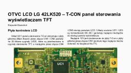
102 | P a g e, , See all of these connection and use thin wire and connect at PCB points., , 102, , ImagineX ElectronicS
Page 106 :
105 | P a g e, , LTA320WT-L15 , STRAP 320WTSL4LV0.0 , PETAL S6CG21551B, , TOSHIBA, SHARP, PANEL LC420WUD (SB) (M2) .LC420WUN SBA1-731-LEFT, P / N, 6870S-0642D - LEFT STRAP.LC420WUN SBA1-731-RIGHT, P / N 6870S-0643D, , Test Case Read Carefully., LC420WUD-SBM2 T-con. Television with 10cm band image at the top of the screen., Also there's the band a few pixels on the right side between the 3rd and 4th from the, top side pads . Gradually fills white with clearly visible transitions between drivers. It, was found on the sagging VGH_M T-con 10.7v to 24.7v with VGH. Strongly heated third, top right side strap when tilting right from T-con VGH_M = 23.5v, VGH = 27.1v and the, picture appears on the left, but with greenish artifacts and without contrast. All connections between the slats and ears in order conditionally, because some go up to 200, ohms but not jump but presumably GSP_REV - 3.2kOm or wrongly location. Honestly, decision yet, but since have information on the panel decided to immediately post in, this section. Burn not see any sense, because it is not clear between what, and make a, hole in the tail easily. While I tend to remove the side lobes. Finally got around to the, panel. It was revealed VGH in the right half. When disconnecting appeared full picture, but with shading and tails on the right side. VGH was clipped on the driver who basked, (third right top). Appeared normal in the upper half of the picture and brake in right., Were then removed the right driver. The left side does not pull the whole screen, which, 105, , ImagineX ElectronicS
Page 107 :
106 | P a g e, , can be seen on a white field on color and dynamic picture all perfect., Connect these points with thin wires., , 106, , ImagineX ElectronicS
Page 114 :
113 | P a g e, , Panel LC320WUE-SAA1 stands in 32PFL5604, Missing the lower half of the, , image, with the heating pours milk. Underestimated VGH to 1V on the two side address, driver, threw jumper panel board. More detailed measurements of stay was not possible, resting visiting relatives, suitcase accidentally left in the trunk before you go to, them second such panel this month with similar defects., , Matrix (panel) - LTA320AB02 T-CON - 320AB02CP2LV0.3, , very popular defect "Running Picture", There are two drivers in positions ICS1 ICS2 and from which signals STVP1, CKVB1,, CKV1 and STVP2, CKVB2, CKV2 go to the row driver say so drayverov1 group and, group 2 drivers (as it is there precisely arranged known only to developers but let's just, say that one group of duplicates another group) and so one group of drivers has a broken case that spoils us a picture, in my case it group1 controlled corresponding signals, with index 1 through driver ICS1. Evaluate to what group accidents Register disconnecting power turns with Von ICS1 And ICS2, and landing legs 1 chips to the body, where no longer run after shots off Von, then that driver controls the group with broken register. might seem that removing power from Von (+28 v) with the desired driver problem is solved, but it is not so, but to become a great picture but eventually 5, minutes if the picture has static objects such as a channel logo (pictured logo and Rossiya24 NTV), the artifacts appear as intermittent bands cm photos. But it is also solved, simply be removed from the board and apply for a driver signals STVP, CKVB, CKV, power Voff (-12v) 8 foot driver chip. And in general, is all almost perfect picture! , Only, fifteen minutes on NTV was seen faintly artifact, almost discernible unless you know, where to look not possible, it is possible to win by increasing negative voltage Voff to16 --- 17volt. Voff I installed 16., 3v, adjustment Voff I realized zener 9,1 v included as, shown in the picture (between the emitter and collector of Q2, to the emitter cathode,, anode collector). This method to combat "running shots" can be applied to other matri113, , ImagineX ElectronicS
Page 120 :
119 | P a g e, , V260B1-L11 and V260B1-L12bring more to the discussion information, this issue - V260B1-L04 REV.C2 Covered:, 1. Identity data pads, 2. Correctness of the information provided in the image signal STV and STV_R ., , 3. Defining and Identifying Facilities lowercase drivers (petals) to the type of, panel (if there are differences between them). Here note - T-CON located on a, separate board and with its location on the plate glass panel., 4. Amendments and additions., , For objectivity give their information for consideration on this issue. producing reconstituted panel V260B1-L11 Rev.C1 T-CON Bracket V260B1-XC11 (Philips, 26PFL5403S/60 TCM2.0E LA) discovered in part difference signal STV and STV_R . Data breakpoints on the petal is not identical . . waveform are identical but are out of, phase . In my case was open signal STV . When duplicating conductor STV_R , as has, been suggested (two equivalent top and bottom lobe) in the photo (quote already corrected version on STV ) - - from the upper lobe of the control point (near to the bar) to, the signal STV_R Bracket - operation panel is restored, but only for a while , until you, have a primary conductor breakage in glass (or contact on cable). With his spontaneous, recovery in the operation after the closure of duplication between the signals obtained, STV and STV_R panel and again becomes defective. In my case (almost immediately revealed when running) observed the effect of "running footage." A colleague came repeated two weeks later - "the cold is no ISO first 15 minutes." I believe that the manifestation of the defect can be varied depending on the degree of resistance to breakage, and recombination it ... I enclose a photo correct location signal STV on the petal panel, V260B1-L11 Rev.C1 and planks overhead T-CON V260B1-XC11 Petal - CBH1 / 8658-B, (the inscriptions top / bottom respectively lobe location relative to the panel) Driver 821SSU371-00B (Philips 26PFL5403S/60 TCM2.0E LA) signal STV_R and its location, (top photo) on the petal driver remains unchanged and the same name, including and, on the bar. Changes and corrections to apply only to the lower (erroneously called, STV_R ) on STV and added point (s) of its origin with straps. Displaying two points signal STV , which comes with a signal to the loop in the panel, but soldered to them is, problematic. Therefore, you can traverse the backup conductor further to the checkpoint, as in the photo - is under the third vertical train drivers from the side of line, drivers. At the bottom (or right) photo reference point is located in the third vertical, driver to the center panel from the side of line. Have an opinion on personal experience, that these messages occur in direct relation to the above error -, , 119, , ImagineX ElectronicS
Page 124 :
123 | P a g e, , Philips 32pf5321/12 faulty RAM K4D263238., , Philips 32PF3320/10, Main LC4.5E AA QD32HL02 REV: 01 and T-con V32BC3, Color distortion in the form of dirty greenish-brown shades (visible on the face of his, grandfather) and lack of semitones (seen on the shirt of his grandfather.), The module T-con voltage VCOM3 instead it was 6,5 V 12V - broken output circuits, AS34-G. The second picture after troubleshooting. AS34-G gamma corrector and defect, quite often worth and Samsung., , 123, , ImagineX ElectronicS
Page 125 :
124 | P a g e, , T260XW05 V0. T-con built on the top plate., Classic problem - periodically lost control signals driver - side screen is dark , then, slowly appear colored vertical stripes . Reach the ear proved difficult - the glass is glued, to the plastic frame. Turn down seemed dangerous - some coppers very close to the, glass. Risk did not turned out that bad contact - at the extreme conclusions , where loop, is attached to the plate. Screw length pressed iron plate with gasket . Three days normal flight . Thought for the future: if you still have to climb into the ear , then it is best, to remove the glass together with the frame , and then break out the relevant section of, wire cutters Worked all night. Solder - did not help. Hence, in the glass. Tore off the, glass from the frame it turned out all the same STV. Throw wire., , 124, , ImagineX ElectronicS
Page 128 :
127 | P a g e, , Panasonic TX-R32LE8., Negative. The problem is T-con, namely the ill-fated gamma corrector. Although it was, much more prosaic. When measuring out voltages the control points: VREFU_L - 8,8 V,, VREFL_L - 0,15 V, VREFL_H - 6,1 V (all voltages removed after repair, so relative). When, continuity strapping Shorty MAX9590 circuit to ground - 25 pin (C360). Banality - solder wicking .., , 127, , ImagineX ElectronicS
Page 132 :
131 | P a g e, , SAMSUNG LA46M81B. Panel LTA460HB05. T-con, 404652FHDSC4L 0.0, Left part of the frame is repeated vertically, right-norm. Left out slightly blurry. That, broke off to find out there was no time. Hurried customers. So just cleared out the loop, on the main board and soldered properly. Every restored. That he managed to tracespread. By the way, was not in place on the board 24S64 Tcon. Set and poured firmware, from Tcon panel LTY320HA03-01., , 131, , ImagineX ElectronicS
Page 133 :
132 | P a g e, , Matrix AUO T420XW01 V0 (LCD TV Sharp LC-42PD2RU), Petal - NOVATEK NT39329H-C0258A, , Defects occur as a periodic appearance of the left vertical braking murky background, (usually on a cold), happened when you click on the top corner, the picture is restored., On the face of an explicit address blade side loop, but rather the power going through it, on the driver side., Tried to catch what supply is lost, but was worn out, only slightly tronesh top dress, with a train, the picture is normalized after recovery images can be switched both day, and two normal., Duplicated once both supply VGH and VGL, passing something., conclusions on a connector J3:, 8 - VGH, 10 - VGL, 12 - U_D aka V3D3, 15 - YDIOU (human), 17 - YCLK (lowercase), 21 - YDE1 (pictured food -5,9 v with a question, do not call with VGL) PS A year has, passed since the date of repair As a result, all duplicated synchronic: YDIOU, YCLK,, YDE1. Concludes that it was necessary to duplicate all at once., , 132, , ImagineX ElectronicS
Page 136 :
135 | P a g e, , Panel LTA320WT-L06 T-CON 320WTC2LV3.7 bracket, 320WTS2LV2.6 SAMSUNG (TV BLAUREN COMFORT 32), The image long loops in dynamic objects, the effect of "icing" and "retardation" fine, arts, when changing a new frame slow disappearance of the previous, OSD - similarly., Static image is normal., , Defect: VON bus interruption in the glass., , After duplication performance tires VON panel restored., , Resistance power and signal conductors in the glass matrix TFT (values ??are rounded, to the range of 5-10%) VON - OPEN!, , VOFF - 15 Om, STV - 300 Om, , VCOMG2 - 100 Om, VCOMG1 - 150 Om, , VST1 - (not identified), CPV1 - 300 Om, 135, , ImagineX ElectronicS
Page 138 :
137 | P a g e, , Panel LC320WUE-SAA1 stands in 32PFL5604,, Missing the lower half of the image, with the heating pours milk. Underestimated VGH, to 1V on the two side address driver threw jumper panel board. More detailed measurements of stay was not possible, resting visiting relatives, suitcase accidentally left in, the trunk before you go to them second such panel this month with similar defects., , 137, , ImagineX ElectronicS
Page 140 :
139 | P a g e, , Model Samsung LE37M87BDX/BWT -Matrix T370HW02 v.2, T-con T370HW02 V0, After replacing the blown capacitors, including but distorted colors. Perhaps this characteristic picture when such a failure - measurements showed that died AS15-F smooth top lighting on color raster, no clarification on smooth gray, white and black, squares. Note the channels and VGMA9 VGMA10., , 139, , ImagineX ElectronicS
Page 143 :
142 | P a g e, , Matrix LG LC470WUE (SA) (A1)., Defect appears within half an hour in the right third of the screen., Pictured are already showing football close-up, and right field is not yet disappeared., Also clearly seen when switching channels when screen goes blank, the remnants of a, galloping right image., , Pads T7C75A1 Do matrix 4 lobe on each side. Photo painted with top drivers, working, from the left side. On the right there is no lower petals 3V3, and feeding it the right side, of the screen darkens. If you bind this point to ground via a resistor 200 300Om, the defect does not appear. The fault could touch the bottom of the instrument probe point, 3V3 or heating hairdryer any of the four right drivers. After connecting with the earth,, such a manifestation disappeared. It remains unclear what potential db at the lowest, point in the right 3V3 drivers, same as in the left, or tied to ground?, , 142, , ImagineX ElectronicS
Page 144 :
143 | P a g e, , Matrix M260TWR1 ,INFOVISION OPTOELEKTRONICS,TV Akai, LTA-26N680HCP., The white screen and with warming up vertical strips. Were in VGL break - 8.6v, VGH, 19.4v, 3.3v.On an ear of the Piglet only two. It was necessary to solder to paths. I added, a photo of drawing of side pad from my records. To the right of the driver to glass go, some of paths, then the round patch, again the path following more widely to it we solder VGH19.4v, to the second wide VGL - 8.6v, to the third wide 3,3v. I hope with such, , 143, , ImagineX ElectronicS
Page 145 :
144 | P a g e, , explanation it will be more clear., , Matrix LC420WUL SB M2 marking driver (lobe) 943ST65, , Hinders right half. Open signal OPT_P, control the direction of signal flow through the, GSP drivers. For the right half of the matrix OPT_P = "0" for the left OPT_P = "1". Accord144, , ImagineX ElectronicS
Page 146 :
145 | P a g e, , ingly, if you look at the ear (right side of the matrix) input signal GSP left out - right., And vice versa (for the left side of the matrix) input signal GSP right way - on the left., , 145, , ImagineX ElectronicS
Page 149 :
148 | P a g e, , M, MO, OD, DEELL:: LLN, NT, T44666655FFXX//XXA, AA, A LLCCD, DT, TVV, SYMPTOMS: Lost brightness when you replaced main pcb., CURE: Because main pcb bn94-01199e is designed to work with both models, lnt4665fx/xaa and lnt4661fx/xaa when you replaced the board is possible to lost the, brightness. go in service mode and turn value lvds byte from 8 to 10., , M, MO, OD, DEELL:: LLN, NSS44005511D, DXX//XXA, AA, A LLCCD, DT, TVV, SYMPTOMS: Dead backlight flashes on then off, CURE: Unit would flash on then off and audio would work. You could see video with a, flashlight. Sometimes unit would stay on and run if you cycled on and off many times., Found bad solder connection on ip board Ti801 on primary side. Reordered and corrected problem., , M, MO, OD, DEELL::, LLN, N4466A, A554400PP22FFXXZZA, A,,LLN, N4466A, A885500SS11FFXXZZA, A,,LLN, N4466A, A663300M, M11FFXXZZA, A,,LLN, N4466A, A558800PP66FFXXZZA, A,,LLN, N5522, A, A553300PP11FFXXZZA, A,,LLN, N5522A, A775500R, R11FFXXZZA, A.., SYMPTOMS: Unit cycles on/off during startup., CURE: if the unit tries to turn on but begins to cycle on and off before any video is displayed and all of the SMPS voltages are good, disconnect the LVDS cable at the t-con, board. If the set starts and the backlights come on, replace the t-con board. If the set, does not start, disconnect the LVDS cable at the main board. If the set starts, replace the, LVDS cable. If the set still does not startup, replace the main board., , M, MO, OD, DEELL:: LLN, NT, T33225533H, HXX//XXA, AA, A LLCCD, DT, TV, V, , SYMPTOMS: After a few minutes when TV warms-up picture becomes distorted., CURE: 10-15 minutes after you turned on the unit panel warms-up and picture becomes distorted, If you just push the TV’s frame picture becomes even more distorted,, On the back of the panel the control i.c area is very hot. Replace the panel to fix the, problem., , M, MO, OEELL:: LLN, N3322A, A445500CC11D, DXXZZA, A,,LLN, N3322A, A445500CC11H, HXXZZA, A,,LLN, N3322A, A445500CC33H, HXXZZA, A,,LLN, N3322A, A333300JJ11D, DXXZZ, A, A,,LLN, N3322A, A333300JJ11N, NXXZZA, A LLCCD, D.., SYMPTOMS: Video will intermittently turn mostly white. White display with a, faint image of osd and video in the background., Video will intermittently turn mostly white with the osd barely visible in the background. Even a black image or when the panel should not be showing any video, it is, white’s found that one of the sub-boards inside the panel, the boards that the ribbon, cable from the t-con connect to, are not seated properly and the larger smd capacitors, on the board are intermittently making contact with the metal frame of the set, effectively creating a short to ground. This is one of the panels that is mounted upside down,, so the stand mounts just below and behind the panel frame. Any slight pressure from, the stand can cause the frame to make contact. In many cases, the tv can be slightly, flexed to make this issue occur., 148, , ImagineX ElectronicS
Page 152 :
151 | P a g e, , Samsung LE26S81B, The failure of the synchronization is shown only when receiving a signal from the antenna, menus and AV signals reproduced without problems., Cure: The fault on the circuit formation 5V power tuner S152., , 151, , ImagineX ElectronicS
Page 153 :
152 | P a g e, , Samsung LE37S81BX / BWT, Fault : Image distortion, Cure: When you install an alternate panel BN07-00446A (CLAA370WA03SC), instead, of the original BN07-00366A (CLAA370WA03S) possible occurrence of this problem, with the image. TV must be attached to flash firmware and after flashing, change the, value of Spread Spectrum -> FBE Spectrum to "0"., , 152, , ImagineX ElectronicS
Page 154 :
153 | P a g e, , Sharp LC-42DH77RU,, Problem: There is a Test Pattern when start the LCD TV., , AU Optronics LCD panel T315XW01 V5, Panel Testing:: Mode AGMODEN closed point on the ground - starts to finger test, fields in a circle. To open the exit.., 153, , ImagineX ElectronicS
Page 155 :
154 | P a g e, , Some LCD,LED TV Factory Reset, Over time, I have created a listing of manufacturers and their factory reset/factory, mode procedures that may help others. This list is from my own experience, and is by, no means complete for any given manufacturer. Some have been found by searching, the internet, some by trial and error. I hope some may find this information useful., , **** WARNING!!!! ******, Some of these procedures may allow you to enter factory service modes. IF YOU DO, NOT KNOW WHAT YOU ARE DOING, DO NOT MAKE CHANGES TO SETTINGS IN FACTORY MODES!! Improper settings may cause undesired operation, and could result in, a situation where your TV cannot boot/turn on., YOU ARE USING THESE PROCEDURES AT YOUR OWN RISK!!, Factory Resets / modes For all listed procedures start with TV on, in TV mode, unless otherwise instructed. After procedure is complete, unplug set and re-plug in to, finish reset. If more than one procedure is listed for a given manufacturer, try the different ones until you see which one works for your set., Samsung (European), Power off, Info - Menu - Mute - Power, then find factory reset and execute option., LG/Zenith:, Hold MENU on TV and MENU on remote for 5~10 seconds, then select reset option., NEC:, 154, , ImagineX ElectronicS
Page 156 :
155 | P a g e, , While powering on hold "MENU" or "INPUT" on TV, depending on model. (Only disables error lock out/buffer and puts TV in temporary service mode.), To reset to factory, on remote, Off Timer - Menu - Exit - Off Timer, then select reset, option., , Vizio Service Menu Method 1, 1. Turn The TV off., 2. Press and hold the {CH +} & {CH -} buttons on the TV., 3. Then press and release the {POWER} button on the TV., 4. Release the {CH +} & {CH -} buttons., 5. Now press the {MENU} button on the remote., 6. You should get your regular menu up, but with a "F" in the bottom right corner of, the menu (This is for factory)., 7. Press and hold the {MENU} button for few seconds., 8. The Service Menu will be displayed., Vizio Service Menu Method 2, 1. Turn The TV off., 2. Press and hold the {CH +} & {CH -} buttons on the TV., 3. Then press and hold the {POWER} button on the TV., 4. Keep all three buttons pressed for few seconds., 5. Now press the {MENU} button on the remote., 6. You should get your regular menu up, but with a "F" in the bottom right corner of, the menu (This is for factory)., 7. Press and hold the {MENU} button for few seconds., 8. The Service Menu will be displayed., Vizio Service Menu Method 3, 1. Press and hold the {EXIT} button on the remote for 3 seconds then release it., 2. Then press the {1} {2} {3} buttons on the remote., 3. To exit, press the {EXIT} button., --------------------------------------------------------------GV42L FHDTV10A / JV50 / SV42 / SV320XVT / SV370XVT / SV420M /, SV470M / SV420XVT1A / SV470XVT1A /, VECO320L1A / VO22L / VO32 / VO37 / VO47L / VOJ320 / VOJ370 / VP322 /, VP42 HDTV20A / VP422 / VS420LF1A /, VU42 / VW32 / VW37 / VW42 / VX20 / VX32 / VX37 HDTV10A /VX42, Push "Menu" on remote and then push "Vol-" and "Input" on keypad, GV46 / P50HDM / P50HDTV10A, Press "Ch-" and "Ch+" buttons together once on keypad, GV42 / L42 / VP42HDTV10A / VP50 / VX37, Press and release "Menu" on keypad. Hold "Ch-" and "Ch+" buttons on keypad, then, hold "Menu" on remote., P42 Hold "Ch+" and "Ch-" along with "Power" on keypad. OSD will show "F" on right, bottom portion of OSD., 155, , ImagineX ElectronicS
Page 158 :
157 | P a g e, , Hisense In customer menu go to “Parental” enter 0000 then select “Clean All” then, power the set off and back on and first time setup menu will be there., , For some models, same as above model except in menu it is labeled “Lock”, , Insignia input 2580 (tv is on), Mitsubishi Menu 123 or menu 2470 (tv is on), Panasonic Hold vol- on TV, press and hold menu button on remote, Philips Push menu, select”Features” then select “current software info” push, 062596-info on remote then push info again then red “initialize appears and changes, color then complete. Push power button to exit, , TV is on, push 062596-info on remote, then push info again, red ”initialized” appears, it turns green when completed, then push power button to exit, , Polariod, Hold vol- and chan- or hold vol+ and chan+ (tv is on), , Proscan, In customer menu go to setup, select parental control menu, enter 0000 then select, “clear channel list”., , RCA Menu 1147, Sanyo Hold vol down on TV, press and hold #1 button on remote, vol will jump to, halfway and set shuts off. Turn back on have 1st time setup screen., , Samsung Mute 182 power (tv is off) (On some models, Factory Reset is on this, menu, on some, you must go into the “Options” submenu, , Seiki Menu 0000, Sharp (Note – On Sharp models, you will need to look through the menus to find, , the reset option) menu 1999 menu, 3481 menu 1147 While holding vol– & input buttons on tv plug in set when “k” appears push vol– & chan-, , Sony Hold “arrow up” on remote and push power button on tv (tv is on), Symphony Source/input 2580, , 157, , ImagineX ElectronicS
Page 159 :
158 | P a g e, , Toshiba On Menu, select “Installation”, then “System Information” press the right, arrow button, (“System Information” will change to “Factory Reset” or something, similar) follow on-screen instructions, , Vision Quest Source/input 2580, Vizio In customer menu under “Help” tab is Factory Default enter 0000, , Email me if you found error in this eBook, , IIm, mrraann__uussaa99@, @yyaahhoooo..ccoom, m, IIm, mrraannuussaa9900@, @ggm, maaiill..ccoom, m, , EEN, ND, DO, OFF PPA, AR, RT, TO, ON, NEE, , 158, , ImagineX ElectronicS