Page 1 :
Fatima Michael College of Engineering & Technology, , EE6702 PROTECTION & SWITCHGEAR, Syllabus, , Fatima Michael College of Engineering & Technology
Page 2 :
Fatima Michael College of Engineering & Technology, , Fatima Michael College of Engineering & Technology
Page 3 :
Fatima Michael College of Engineering & Technology, , Power system, basics, Fatima Michael College of Engineering & Technology
Page 4 :
Electric Power System, Fatima Michael College of Engineering & Technology, , Electricity is generated at a power plant (1),, voltage is “stepped-up” for transmission(2), , Energy travels along a transmission line to the area where the power is needed (3), , voltage is decreased or “stepped-down,” at another substation (4),, & a distribution power line (5), carries that electricity until it reaches a home or business (6)., , Fatima Michael College of Engineering & Technology
Page 5 :
Fatima Michael College of Engineering & Technology, , SINGLE LINE DIAGRAM, , Fatima Michael College of Engineering & Technology
Page 6 :
Fatima Michael College of Engineering & Technology, , UNIT, , 1, , INTRODUCTION, Presented by, V.VIGNESH BABU,AP/EEE, FATIMA MICHAEL College of Engg & Tech, , Fatima Michael College of Engineering & Technology
Page 7 :
Fatima Michael College of Engineering & Technology, , UNIT 1 Syllabus, • Importance of protective schemes for electrical, apparatus and power system, • Qualitative review of faults and fault currents, • Relay terminology – definitions, • Essential qualities of protection, • Protection against over voltages due to lightning and, switching - arcing grounds, • Peterson Coil, • Ground wires, • surge absorber and diverters, • Power System Earthing – neutral Earthing, • Basic ideas of insulation coordination., Fatima Michael College of Engineering & Technology
Page 8 :
Fatima Michael College of Engineering & Technology, , Importance of protective, schemes for electrical, apparatus and power system, , Fatima Michael College of Engineering & Technology
Page 9 :
Fatima Michael College of Engineering & Technology, , PROTECTION SYMBOL, two-winding, transformer, , current transformer, , two-winding, transformer, , voltage transformer, , generator, , capacitor, , bus, , circuit breaker, , transmission line, , circuit breaker, , delta connection, , fuse, , wye connection, , surge arrestor, , static load, , disconnect, , Fatima Michael College of Engineering & Technology
Page 10 :
Fatima Michael College of Engineering & Technology, , Primary Equipment & Components, • Transformers - to step up or step down voltage level, • Breakers - to energize equipment and interrupt fault current to, isolate faulted equipment, • Insulators - to insulate equipment from ground and other phases, • Isolators (switches) - to create a visible and permanent isolation, of primary equipment for maintenance purposes and route power, flow over certain buses., • Bus - to allow multiple connections (feeders) to the same source, of power (transformer)., , Fatima Michael College of Engineering & Technology
Page 11 :
Fatima Michael College of Engineering & Technology, , Primary Equipment & Components, • Grounding - to operate and maintain equipment safely, • Arrester - to protect primary equipment of sudden overvoltage, (lightning strike)., • Switchgear – integrated components to switch, protect, meter, and control power flow, • Reactors - to limit fault current (series) or compensate for charge, current (shunt), • VT and CT - to measure primary current and voltage and supply, scaled down values to P&C, metering, SCADA, etc., • Regulators - voltage, current, VAR, phase angle, etc., Fatima Michael College of Engineering & Technology
Page 12 :
Fatima Michael College of Engineering & Technology, , Why A System Needs Protection?, • There is no ‘fault free’ system., • Ensure safety of personnel., • Usually faults are caused by breakdown, of insulation due to various reasons:, system over current, over voltage,, lighting, etc., , Fatima Michael College of Engineering & Technology
Page 13 :
Fatima Michael College of Engineering & Technology, , Fatima Michael College of Engineering & Technology
Page 14 :
Fatima Michael College of Engineering & Technology, , Fatima Michael College of Engineering & Technology
Page 15 :
Fatima Michael College of Engineering & Technology, , Fatima Michael College of Engineering & Technology
Page 16 :
Fatima Michael College of Engineering & Technology, , POWER SYSTEM WITHOUT PROTECTION, • Short circuits and other abnormal conditions, often occur on the power system. The heavy, current associated with short circuits is likely to, cause damage to the equipment, , Fatima Michael College of Engineering & Technology
Page 17 :
Fatima Michael College of Engineering & Technology, , Element of protection system, (1)Current and Voltage Transformers, (2)Relays, (3)Circuit breakers, (4)Batteries, (5)Fuses, (6)Lighting Arresters, , Fatima Michael College of Engineering & Technology
Page 18 :
Fatima Michael College of Engineering & Technology, , Current transformer, • Current transformer consists at least of two secondary windings., • The first winding is usually designed for measuring, the second is, used for protection., • The secondary of current transformers are almost connected in star, , Fatima Michael College of Engineering & Technology
Page 19 :
Fatima Michael College of Engineering & Technology, , Voltage transformer, • Voltage transformer is often consists of two windings., • The first winding is connected in star, and the stare, point must be earthed., • The second winding is connected as open delta., , VS, Relay, , VP, , Fatima Michael College of Engineering & Technology
Page 20 :
Fatima Michael College of Engineering & Technology, , Relay Purpose, Isolate controlling circuit from controlled circuit., Control high voltage system with low voltage., Control high current system with low current., Logic Functions, , , Fatima Michael College of Engineering & Technology
Page 21 :
Fatima Michael College of Engineering & Technology, , Advantages for Using, Protective Relays, • Detect system failures when they occur, and isolate the faulted section from the, remaining of the system., • Mitigating the effects of failures after, they occur., • Minimize risk of fire, danger to personal, and other high voltage systems., , Fatima Michael College of Engineering & Technology
Page 22 :
Fatima Michael College of Engineering & Technology, , CIRCUIT BREAKER, •, •, •, •, , Low voltage circuit breaker, Magnetic circuit breaker, Medium voltage circuit breaker, High voltage circuit breaker, , Fatima Michael College of Engineering & Technology
Page 23 :
Fatima Michael College of Engineering & Technology, , Battery bank, • Battery bank are called as, backbone of protection system, • Emergency use for power, system, , Fatima Michael College of Engineering & Technology
Page 24 :
Fatima Michael College of Engineering & Technology, , Fuse, • Fuses are selected to allow passage of normal, current and of excessive current only for short, periods., • It is used to protect the low voltage or current, rating devices, , Fatima Michael College of Engineering & Technology
Page 25 :
Fatima Michael College of Engineering & Technology, , Lighting arrester, • A lightning arrester is a device used on, electrical power system to protect the, insulation damaging effect of lightning., • All lighting arrester are earthed, , Fatima Michael College of Engineering & Technology
Page 26 :
Fatima Michael College of Engineering & Technology, , What is Switchgear ?, • Switchgear is the combination of switches,, fuses or circuit breakers(CB) used to, control , protect & isolate electrical, equipment., • It is used de-energize equipment & clear, faults., , Fatima Michael College of Engineering & Technology
Page 28 :
Fatima Michael College of Engineering & Technology, , Function wise categories, • Automatic & Manual operation, { example: Circuit breaker ,MCB , MCCB }, • Only automatic operation, , Fuse, • Only manually activated / operated, , Isolator, LBS, , Fatima Michael College of Engineering & Technology
Page 30 :
Fatima Michael College of Engineering & Technology, , Qualitative review of, faults & fault currents, , Fatima Michael College of Engineering & Technology
Page 31 :
Fatima Michael College of Engineering & Technology, , NATURE & CAUSES OF FAULTS, •Insulation failure., •Conducting path failure., •Over voltages due to lightening or switching surges., •Puncturing or breaking of insulators., •Failure of conducting path due to broken conductors., •Failure of solid insulation due to aging, heat, moisture,, overvoltage , accidental contact with earth or earth screens,, flash over voltages and etc.,, , Fatima Michael College of Engineering & Technology
Page 32 :
Fatima Michael College of Engineering & Technology, , FAULT IN POWER SYSTEM, , , , , A power system fault may be defined as any, condition or abnormality of the system which, involves the electrical failure of primary, equipment such as generators, transformers,, busbars, overhead lines and cables and all other, items of plant which operate at power system, voltage., Electrical failure generally implies one or the, other (or both) of two types of failure, namely, insulation failure resulting in a short-circuit, condition or conducting path failure resulting in, an open-circuit condition, the former being by far, the more common type of failure., , Fatima Michael College of Engineering & Technology
Page 33 :
Fatima Michael College of Engineering & Technology, , FAULT IN POWER SYSTEM, Symmetrical, , fault, , Faults giving rise to equal currents in lines, displaced by, equal phase angles i.e 120o in three phase, systems., Example: short circuit of all three phase, conductors of a cable at a single location, , Unsymmetrical, , fault, , Faults in which not all the line currents are equal, and not all have the same phase., Example (any one): single phase line to ground, fault (L-G), two phase to ground (LL-G) fault and, phase to phase (L-L) fault., , Fatima Michael College of Engineering & Technology
Page 34 :
Fatima Michael College of Engineering & Technology, , Abnormalities in Power, Systems, Overcurrent (overload, short circuit, open, circuit), Ground Potential (ungrounded equipment,, touch potentials, step potentials), Surge Voltages (lightning strokes, switching, surges, harmonics), , Fatima Michael College of Engineering & Technology
Page 35 :
Fatima Michael College of Engineering & Technology, , Fault Types (Shunt), , Fatima Michael College of Engineering & Technology
Page 36 :
Fatima Michael College of Engineering & Technology, , Fatima Michael College of Engineering & Technology
Page 37 :
Fatima Michael College of Engineering & Technology, , Frequency of Types of, Faults, Type of, Fault, , %, Occurrence, , SLG, LL, DLG, 3L, , 85, 8, 5, 2 or less, , Fatima Michael College of Engineering & Technology
Page 38 :
Fatima Michael College of Engineering & Technology, , Frequency of Fault Occurrence, Equipment, Overhead lines, Cables, Switchgear, Transformers, CTs and PTs, Control Equipment, Miscellaneous, , % of Total, 50, 10, 15, 12, 2, 3, 8, , Fatima Michael College of Engineering & Technology
Page 39 :
Fatima Michael College of Engineering & Technology, , SYMMETRICAL FAULT, THREE- PHASE FAULT, , THREE PHASE - EARTH, FAULT, , Fatima Michael College of Engineering & Technology
Page 40 :
Fatima Michael College of Engineering & Technology, , UNSYMMETRICAL FAULT, PHASE – PHASE FAULT, , TWO PHASE – EARTH, FAULT, , SINGLE PHASE - EARTH, FAULT, , Fatima Michael College of Engineering & Technology
Page 41 :
Fatima Michael College of Engineering & Technology, , OPEN CIRCUIT FAULT, SINGLE- PHASE OPEN, CIRCUIT, , TWO- PHASE OPEN, CIRCUIT, , THREE- PHASE OPEN, CIRCUIT, , Fatima Michael College of Engineering & Technology
Page 42 :
Fatima Michael College of Engineering & Technology, , Equipments, &, % of total fault, , Over head lines, (50%), Under ground Cable, (9%), , Alternator, (7%), , Causes of Faults, , •Lighting Stroke, •Earthquake, •Icing, •Birds, •Tree branches, •Kite Strings, •Internal Overvoltage, •Damage due to digging, • Insulation failure due to temperature rise, •Failure of Joints, , •Stator & Rotor faults, , Fatima Michael College of Engineering & Technology
Page 43 :
Fatima Michael College of Engineering & Technology, , Equipments &, % of total fault, , Causes of Faults, , Transformer, (10%), , •Insulation Failure, •Faults in tap changer, •Overloading, , Current Transformer, &, Potential Transformer, (12%), , •Overvoltage, •Insulation Failure, •Break of Conductors, •Wrong Connections, , Switch Gear, (12%), , •Insulation failure, •Leakage of air/oil/gas, •Mechanical defect, •Lack of Maintenance, , Fatima Michael College of Engineering & Technology
Page 44 :
Fatima Michael College of Engineering & Technology, , Fatima Michael College of Engineering & Technology
Page 45 :
Fatima Michael College of Engineering & Technology, , Fault Minimization, Improving the quality of machines, equipments,, , installation etc., by improving the design techniques., Adequate & reliable protection system control, Regular maintenance by trained professionals, Effective management of electrical plant, , Fatima Michael College of Engineering & Technology
Page 46 :
Fatima Michael College of Engineering & Technology, , Merits of Fast fault clearing, Helps to avoid permanent damage to equipment &, , components of the apparatus, Reduces the chances of risks like fire hazards, Maintains the continuity of the power supply, Brings back the power system to the normal state, , sooner, , Fatima Michael College of Engineering & Technology
Page 47 :
Fatima Michael College of Engineering & Technology, , Relay terminology –, definitions, , Fatima Michael College of Engineering & Technology
Page 48 :
Fatima Michael College of Engineering & Technology, , , , Relays are electrical, switches that open or close, another circuit under certain, conditions., , Fatima Michael College of Engineering & Technology
Page 49 :
Fatima Michael College of Engineering & Technology, , Protective relays are devices which, monitor power system conditions and, operate to quickly and accurately isolate, faults or dangerous conditions. A well, designed protective system can limit, damage to equipment, as well as minimize, the extent of associated service, interruption., , Fatima Michael College of Engineering & Technology
Page 50 :
Fatima Michael College of Engineering & Technology, , , , , , , Isolate controlling circuit from controlled circuit., Control high voltage system with low voltage., Control high current system with low current., Logic Functions, , Fatima Michael College of Engineering & Technology
Page 51 :
Fatima Michael College of Engineering & Technology, , , , Electromagnetic Relays (EMRs), , , , Solid-state Relays (SSRs), , , , Microprocessor Based Relays, , ◦ There is no mechanical contacts to switch the circuit., , Commonly used in power system monitoring and protection., , Fatima Michael College of Engineering & Technology
Page 52 :
Fatima Michael College of Engineering & Technology, , , , , , , , Electromagnetic Relays (EMRs), ◦ Simplicity, ◦ Not expensive, Solid-state Relays (SSRs), ◦ No Mechanical movements, ◦ Faster than EMR, Microprocessor-based Relay, ◦ Much higher precision and more reliable and durable., ◦ Capable of both digital and analog I/O., ◦ Higher cost, , Fatima Michael College of Engineering & Technology
Page 53 :
Fatima Michael College of Engineering & Technology, , , , , , Detect system failures when they occur and, isolate the faulted section from the remaining of, the system., Mitigating the effects of failures after they occur., Minimize risk of fire, danger to personal and, other high voltage systems., , Fatima Michael College of Engineering & Technology
Page 54 :
Fatima Michael College of Engineering & Technology, , Fatima Michael College of Engineering & Technology
Page 55 :
Fatima Michael College of Engineering & Technology, , Components of Power System Protection, Decides whether system, quantities are normal or, abnormal (Brain of the, System Protection), , Power, System, , Transducers, (PT & CT), , These devices change, electrical quantities to, level relays can use, i.e.,, 5 amperes, 115 volts, , Relay, , Circuit, Breaker, , * If quantities are normal,, no signal is sent to breaker, * If quantities are abnormal,, signal is sent to breaker to, trip, , Fatima Michael College of Engineering & Technology
Page 56 :
Fatima Michael College of Engineering & Technology, , Primary Relay: relay connected directly in the circuit, Secondary Relay: relay connected to the protected circuit, through CT & VT., Auxiliary Relay: relay operate in response to opening or, closing of another relay., Measuring Relay: It performs the measurement of, normal & abnormal conditions in the power system., Electro Magnetic Relay: It operates on the principle of, Electromagnetic induction., Static Relay(Solid-state relay): They use diodes ,, transistors , SCRs , Logic gates etc., (Static circuit is the measuring circuit & no moving parts), Microprocessor Based Relay: All functions of a relay can, done by using microprocessor . Relays are programmable., µP can compare , compute and send trip signals., , , Fatima Michael College of Engineering & Technology
Page 57 :
Fatima Michael College of Engineering & Technology, , Thermal Relay: It operates on the principle of Electrothermal effect., Distance Relay: relay measures the impedance or, reactance or admittance., Impedance Relay: relay measures the impedance of the, transmission line., Reactance Relay: relay measures the reactance of the, transmission line., Over-current Relay: relay operates when the current, exceeds a pre-set value., Under-voltage Relay: relay operates when the voltage, falls a pre-set value., Directional Relay: relay able to sense whether fault lies in, forward or reverse direction., Polarized Relay: relay depends on the direction of the, current., , , Fatima Michael College of Engineering & Technology
Page 58 :
Fatima Michael College of Engineering & Technology, , Differential Relay: it measures the difference b/w 2 actual, quantities., Earth fault Relay: It is used for protection of element of a, power system against Earth faults., Phase fault Relay: It is used for protection of element of a, power system against phase faults., Negative Sequence Relay: relay uses negative sequence, current as its actuating quantity., Zero Sequence Relay: relay uses zero sequence current as, its actuating quantity., , , Fatima Michael College of Engineering & Technology
Page 59 :
Essential Qualities of, protection, Fatima Michael College of Engineering & Technology, , or, Requirement of Protective, System, , Fatima Michael College of Engineering & Technology
Page 60 :
Fatima Michael College of Engineering & Technology, , Reliability, , • assurance that the protection will, perform correctly., , Selectivity, , • maximum continuity of service with, minimum system disconnection., , Sensitivity, , • To detect even the smallest fault,, current or system abnormalities and, operate correctly at its setting, , Speed, , • minimum fault duration and, consequent equipment damage and, system instability., , Simplicity, , • minimum protective equipment and, associated circuitry to achieve the, protection objectives., , Fatima Michael College of Engineering & Technology
Page 61 :
Fatima Michael College of Engineering & Technology, , Reliability, The level of assurance that the relay will function, as intended., Reliability denotes:, Dependability - certainty of correct operation, Security - assurance against incorrect operation, , Sensitivity, Relaying equipment must be sufficiently sensitive, so that it will operate when required, Must discriminate normal from abnormal, conditions., Fatima Michael College of Engineering & Technology
Page 62 :
Fatima Michael College of Engineering & Technology, , Selectivity, Performance of protective devices to select between, those conditions for which prompt operation and, those for which no operation, or time delay, operation is required., Isolate faulted circuit resulting in minimum, interruptions., Implemented through “Zone of Protection”, Speed, Remove a fault from the power system as quickly, as possible, Classification:, Instantaneous - no intentional delay, High Speed - less than 3 cycles, Time-Delay - intentional time delay, Fatima Michael College of Engineering & Technology
Page 63 :
Fatima Michael College of Engineering & Technology, , Power System, Earthing, •Neutral Earthing/Grounding, •Peterson coil, •Arcing Grounds, Fatima Michael College of Engineering & Technology
Page 64 :
Fatima Michael College of Engineering & Technology, , The process of connecting the metallic frame (i.e., non-current carrying part) of electrical, equipment or some electrical part of the system, to earth (i.e. soil) is called grounding or, earthing., Grounding or earthing may be classified as :, (i) Equipment grounding, (ii) System grounding, , Fatima Michael College of Engineering & Technology
Page 65 :
Fatima Michael College of Engineering & Technology, , Equipment Grounding, The process of connecting non-current-carrying, , metal parts of the electrical equipment to earth., , System Grounding, •The process of connecting some electrical part of the, power system to earth (i.e. soil) is called system, grounding., , Fatima Michael College of Engineering & Technology
Page 66 :
Fatima Michael College of Engineering & Technology, , Neutral, Earthing, Fatima Michael College of Engineering & Technology
Page 67 :
Fatima Michael College of Engineering & Technology, , Neutral Grounding, Connecting neutral point to earth (i.e. soil) either, , directly or some circuit element, (e.g. resistance, reactance , Peterson coil etc.), is called neutral grounding., , Neutral grounding provides protection to equipment., , (during earth fault, the current path is completed, neutral), , Fatima Michael College of Engineering & Technology
Page 68 :
Fatima Michael College of Engineering & Technology, , Advantages of Neutral Grounding, (i) Voltages of the healthy phases do not exceed line to, ground voltages i.e. they remain nearly constant., (ii) The high voltages due to arcing grounds are, eliminated., (iii) Life of insulation is long., (iv) The over voltages is reduced., (v) It provides greater safety to personnel and equipment., (vi) It provides improved service reliability., (vii)Operating and maintenance expenditures are, reduced., Fatima Michael College of Engineering & Technology
Page 69 :
Fatima Michael College of Engineering & Technology, , Methods of Neutral Grounding, (i) Solid or effective grounding, (ii) Resistance grounding, (iii) Reactance grounding, (iv) Peterson-coil grounding, (v) Voltage transformer earthing, , Fatima Michael College of Engineering & Technology
Page 70 :
Fatima Michael College of Engineering & Technology, , (i) Solid or effective grounding, , Fatima Michael College of Engineering & Technology
Page 71 :
Fatima Michael College of Engineering & Technology, , When the neutral point of a 3-phase system is, directly connected to earth (i.e. soil) is called, solid grounding or effective grounding., When an earth fault occurs between earth and, any one phase , the voltage to earth of the faulty, phase becomes zero, but the healthy phases, remains at normal phase values., Fault current(IF) completely nullified by, capacitive current(IC), , Fatima Michael College of Engineering & Technology
Page 72 :
Fatima Michael College of Engineering & Technology, , (ii) Resistance grounding, , When the neutral point of a 3-phase system (e.g. 3-phase generator,, 3-phase transformer etc.) is connected to earth (i.e. soil) through a resistor,, it is called resistance grounding., Fatima Michael College of Engineering & Technology
Page 73 :
Fatima Michael College of Engineering & Technology, , Advantages:, , , , , , By adjusting the value of R, the arcing grounds can be minimized., It improves the stability, Less interference, Minimize hazards, , Disadvantages:, , , , , , By adjusting the value of R, the arcing grounds can be minimized., It improves the stability, Less interference, Minimize hazards, Fatima Michael College of Engineering & Technology
Page 74 :
Fatima Michael College of Engineering & Technology, , (iii) Reactance grounding, , •In this system, a reactance is inserted between the neutral and ground, •The purpose of reactance is to limit the earth fault current., Disadvantages :, (i) In this system, the fault current required to operate the protective device, is higher than that of resistance grounding for the same fault conditions., (ii) High transient voltages appear under fault conditions., Fatima Michael College of Engineering & Technology
Page 75 :
Fatima Michael College of Engineering & Technology, , Fatima Michael College of Engineering & Technology
Page 76 :
Fatima Michael College of Engineering & Technology, , If inductance L of appropriate value is connected in, , parallel with the capacitance of the system, the fault, current IF flowing through L will be in phase, opposition to the capacitive current IC of the system., If L is so adjusted that, , I L = IC, then resultant current in the fault will be zero. This, condition is known as Resonant Grounding., When the value of L of arc suppression coil is, such that the fault current IF exactly balances the, capacitive current IC , it is called resonant grounding., , Fatima Michael College of Engineering & Technology
Page 77 :
Fatima Michael College of Engineering & Technology, , •An arc suppression coil (also called Peterson coil) is an iron-cored coil, connected between the neutral and earth., •The reactor is provided with tappings to change the inductance of the, coil., •By adjusting the tappings on the coil, the coil can be tuned with the, capacitance of the system i.e. resonant grounding can be achieved., , Fatima Michael College of Engineering & Technology
Page 78 :
Fatima Michael College of Engineering & Technology, , • Suppose line to ground fault occurs in the line B at point, F. The fault current IF and capacitive currents IR and IY will, flow as shown in Fig, • Note that IF flows through the Peterson coil (or Arc, suppression coil) to neutral and back through the fault. The, total capacitive current IC is the phasor sum of IR & IY, as shown in phasor diagram in Fig., • The voltage of the faulty phase is applied across the arc, suppression coil. Therefore, fault current IF lags the faulty, phase voltage by 90°., • The current IF is in phase opposition to capacitive, current IC [See Fig]., By adjusting the tappings on the Peterson coil, the, resultant current in the fault can be reduced. If inductance, of the coil is so adjusted that IL= IC , then resultant current, in the fault will be zero., Fatima Michael College of Engineering & Technology
Page 79 :
Fatima Michael College of Engineering & Technology, , Fatima Michael College of Engineering & Technology
Page 80 :
Fatima Michael College of Engineering & Technology, , Fatima Michael College of Engineering & Technology
Page 81 :
Fatima Michael College of Engineering & Technology, , v. Voltage Transformer Earthing, In this method of neutral earthing , the primary of a, , single-phase voltage transformer is connected, between the neutral and the earth as shown in Fig, A low resistor in series with a relay is connected, across the secondary of the voltage transformer. The, voltage transformer provides a high reactance in the, neutral earthing circuit and operates virtually as an, ungrounded neutral system., , Fatima Michael College of Engineering & Technology
Page 82 :
Fatima Michael College of Engineering & Technology, , Fatima Michael College of Engineering & Technology
Page 83 :
Fatima Michael College of Engineering & Technology, , Protection against, over voltages due to, lightning and, switching, Fatima Michael College of Engineering & Technology
Page 84 :
Fatima Michael College of Engineering & Technology, , Protection Against Over Voltage Due, to Lightning & Switching, During Operation , PS equipments such as Generator,, , transformer, Tx.lines may subject to Over Voltage., OV occurs due to Lightning, opening of CB & so on., , Causes Of OV, Internal Cause, , , External Cause, , Fatima Michael College of Engineering & Technology
Page 85 :
Fatima Michael College of Engineering & Technology, , External, , • Lightning, • Tree falls on, Tx.lines causes SC, , Internal, , •, •, •, •, , Insulation Failure, Resonance, Arching Ground, Switching Surges, , Fatima Michael College of Engineering & Technology
Page 86 :
Fatima Michael College of Engineering & Technology, , Types of Over Voltages, *Power Frequency OV, * Switching OV, * Lightning OV, , Fatima Michael College of Engineering & Technology
Page 87 :
Fatima Michael College of Engineering & Technology, , Power Frequency OV, Does not have damaging effects like switching or, , lightning surges, It will be harmful, if sustained for longer duration, Mainly due to, Ground faults, Sudden load rejection, Loose connection, Fatima Michael College of Engineering & Technology
Page 88 :
Fatima Michael College of Engineering & Technology, , Switching OV, Also known as Switching surge or over voltage transient, Sudden rise of voltage for a very short duration in PS, , network is known as transient voltage or voltage surge, An electrical transient appears, if there is sudden change, in the state of energy in PS network. This sudden change, is due to, i., ii., iii., , , , Closing a Switch, Opening a Switch, Occurrence of fault in system, , To control the switching OV , Resistor is inserted, between the contacts while switching off the circuit, , Fatima Michael College of Engineering & Technology
Page 89 :
Fatima Michael College of Engineering & Technology, , Lightning OV, Lightning is an electric discharge between cloud & Earth or between, , clouds., It is basically a huge spark, A large number of discharge occurs between or with in clouds than, , to earth & enough of them terminate on the earth causing serious, hazards., Following actions of the lightning stroke generate transients:, , * Direct Stroke to Phase Conductor, * Stroke to earth very close to line, , Fatima Michael College of Engineering & Technology
Page 90 :
Fatima Michael College of Engineering & Technology, , SURGE, DIVERTER, , Fatima Michael College of Engineering & Technology
Page 91 :
Fatima Michael College of Engineering & Technology, , What is surge ?, Surges disturbances on a power waveform, , that can damage, or destroy equipment, within any home, commercial building, or, manufacturing facility., Surges are measured in microseconds., , Fatima Michael College of Engineering & Technology
Page 92 :
Surge diverters, Fatima Michael College of Engineering & Technology, , A surge diverter is a piece of equipment that, diverts excess voltages to earth, thus protecting, sensitive electrical and electronic equipment., The surge diverter is normally installed in the, main switchboard., , Fatima Michael College of Engineering & Technology
Page 93 :
Fatima Michael College of Engineering & Technology, , Requirement of surge diverter :, It should not pass any current at normal and abnormal, , power frequency voltage., , It should breakdown as quickly as possible after the, , abnormal high frequency voltage arrives., , It should not only protect the equipment for which it is, , used but should discharge current without damaging itself., , It should interrupt power frequency follow current after the, , surge is discharge to ground., , Fatima Michael College of Engineering & Technology
Page 94 :
Fatima Michael College of Engineering & Technology, , Types of surge diverters, Rod gap, Protector tube or expulsion type surge diverter, Valve type surge diverter, , Fatima Michael College of Engineering & Technology
Page 95 :
Fatima Michael College of Engineering & Technology, , 1. Rod gap :, It is a very simple type of diverter and consists of two, , 1.5 cm rods., One rod is connected to the line circuit and the other, rod is connected to earth., The distance between gap and insulator must not be, less than one third of the gap length so that the arc, may not reach the insulator and damage it., The rod gap should be so set that it breaks down to a, voltage not less than 30% below the voltage withstand, level of the equipment to be protected., Fatima Michael College of Engineering & Technology
Page 96 :
Fatima Michael College of Engineering & Technology, , Rod gap type surge diverter :, , Fatima Michael College of Engineering & Technology
Page 97 :
Fatima Michael College of Engineering & Technology, , The string of insulators for an overhead line on, , the bushing of transformer has frequently a rod, gap across it., Under normal operating conditions, the gap, remains non-conducting., On the occurrence of a high voltage surge on the, line, the gap sparks over and the surge current is, conducted to earth., In this way excess charge on the line due to the, surge is harmlessly conducted to earth, , Fatima Michael College of Engineering & Technology
Page 98 :
Fatima Michael College of Engineering & Technology, , Limitations :, After the surge is over, the arc in the gap is maintained, , by the normal supply voltage, leading to short-circuit, on the system., The rods may melt or get damaged due to excessive, heat produced by the arc., The climatic conditions (e.g. rain, humidity,, temperature etc.) affect the performance of rod gap, arrester., The polarity of the surge also affects the performance, of this arrester., Fatima Michael College of Engineering & Technology
Page 99 :
Fatima Michael College of Engineering & Technology, , 2.Expulsion type surge diverter, This type of arrester is also called ‘protector tube’ and, , is commonly used on system operating at voltages up, to 33kV., It essentially consists of a rod gap in series with a, second gap enclosed within the fiber tube., The gap in the fiber tube is formed by two electrodes., The upper electrode is connected to rod gap and the, lower electrode to the earth., , Fatima Michael College of Engineering & Technology
Page 100 :
Fatima Michael College of Engineering & Technology, , Expulsion type lightning arrester, , Fatima Michael College of Engineering & Technology
Page 101 :
Fatima Michael College of Engineering & Technology, , The series gap is set to arc over at a specified voltage, , lower than the withstand voltage of the equipment to, be protected., The follow-on current is confined to the space inside, the relatively small fibre tube., Part of the tube material vaporizes, and the high, pressure gases so formed are expelled through the vent, at the lower end of the tube, causing the power followin arc to be extinguished., The device, therefore, has the desired self-clearing, property., Fatima Michael College of Engineering & Technology
Page 102 :
Fatima Michael College of Engineering & Technology, , Advantages, They are not very expensive., They can be easily installed., They are improved form of rod gap arresters as they, , block the flow of power frequency follow currents., , Fatima Michael College of Engineering & Technology
Page 103 :
Fatima Michael College of Engineering & Technology, , Limitations, An expulsion type arrester can perform only limited, , number of operations as during each operation some, of the fiber material is used up., This type of arrester cannot be mounted on enclosed, equipment due to discharge of gases during operation., Due to the poor volt/amp characteristic of the arrester,, it is not suitable for protection of expensive equipment, , Fatima Michael College of Engineering & Technology
Page 104 :
3. Valve type, , Fatima Michael College of Engineering & Technology, , Valve type arresters incorporate non linear, , , , , , , , resistors and are extensively used on systems,, operating at high voltages., It consists of two assemblies (i) series spark gaps, and (ii) non-linear resistor discs, The non-linear elements are connected in series, with the spark gaps. Both the assemblies are, accommodated in tight porcelain container., The spark gap is a multiple assembly consisting, of a number of identical spark gaps in series., Each gap consists of two electrodes with fixed, gap spacing., Fatima Michael College of Engineering & Technology
Page 105 :
Fatima Michael College of Engineering & Technology, , The spacing of the series gaps is such that it will, , , , , , , withstand the normal circuit voltage., An over voltage will cause the gap to break down, causing the surge current to ground via the nonlinear resistors., The non-linear resistor discs are made of, inorganic compound such as thyrite or metrosil., These discs are connected in series., The non-linear resistors have the property of, offering a high resistance to current flow when, normal system voltage is applied, but a low, resistance to the flow of high surge currents., Fatima Michael College of Engineering & Technology
Page 106 :
Fatima Michael College of Engineering & Technology, , When the surge is over the non linear resistor, , assume high resistance to stop the flow of, current., , Fatima Michael College of Engineering & Technology
Page 107 :
Fatima Michael College of Engineering & Technology, , Under normal conditions, the normal system, , voltage is insufficient to cause the breakdown of, air gap assembly., On the occurrence of an over voltage, the, breakdown of the series spark gap takes place, and the surge current is conducted to earth via, the nonlinear resistances., Since the magnitude of surge current is very, large, the nonlinear elements will offer a very low, resistance to the passage of surge., The surge will rapidly go to earth instead of being, sent back over the line., Fatima Michael College of Engineering & Technology
Page 108 :
Fatima Michael College of Engineering & Technology, , ADVANTAGES :, , They provide very effective protection against, , surges., They operate very rapidly taking less than a, second, The impulse ratio is practically unity., , Fatima Michael College of Engineering & Technology
Page 109 :
Fatima Michael College of Engineering & Technology, , Limitations :, They may fail to check the surge of very steep, , wave front reaching the terminal apparatus. This, calls for additional steps to check steep fronted, waves., Their performance is adversely affected by the, entry of moisture into the enclosure. This, necessitates effective sealing of the enclosure at, all times., , Fatima Michael College of Engineering & Technology
Page 110 :
Fatima Michael College of Engineering & Technology, , Surge, Absorber, Fatima Michael College of Engineering & Technology
Page 111 :
Fatima Michael College of Engineering & Technology, , Surge Absorber, The Device which reduces the steepness of the wave, , front of a particular surge & thus minimizes the danger, due to over voltage is known as surge absorber., , Note:, Surge Diverter : Diverts the Surge to earth, Surge Absorber : Absorbs the Surge energy, , Fatima Michael College of Engineering & Technology
Page 112 :
Fatima Michael College of Engineering & Technology, , Types of Surge Absorber, Ferranti Surge absorber, ERA, , Surge absorber, , Fatima Michael College of Engineering & Technology
Page 113 :
Fatima Michael College of Engineering & Technology, , Ferranti Surge absorber, It consists of an air core inductor, , Series, , connected, , Dissipater, , in, , line, , &, , surrounded by an earth metallic sheet, (ie) dissipater., Whenever a travelling wave is incident, , on the surge absorber, energy is, transformed by mutual inductance, between coil & dissipater. ie., the, energy contained in the wave is, dissipated in the form of heat., , Air cored inductor, , Because of the series inductance the, , steepness, , of, , the, , reduced., , Fatima Michael College of Engineering & Technology, , wave, , is, , also
Page 114 :
Fatima Michael College of Engineering & Technology, , ERA Surge Absorber, Improved form of Surge absorber is, , the, , Electrical, , Research, , Association type surge filter., G – Gap ; E – Expulsion gap, When a wave reaches the L, a high, , voltage is induced across it causing, the gap G to breakdown putting, the R and E into circuit., Thus incoming wave get flattened, , by L & R and its amplitude is, reduced by E., , Fatima Michael College of Engineering & Technology
Page 115 :
Fatima Michael College of Engineering & Technology, , basic ideas of, insulation, coordination, Fatima Michael College of Engineering & Technology
Page 116 :
Fatima Michael College of Engineering & Technology, , Insulation Coordination, Correlating (link) apparatus insulation with insulation, , of the protective device to achieve overall protection is, known as insulation coordination., The insulation strength of various equipments should, , be higher than that of lightning arresters and other, surge protective devices., , Fatima Michael College of Engineering & Technology
Page 117 :
Fatima Michael College of Engineering & Technology, , In its simplest form,, , Insulation Coordination, is the selection of, , insulation strength., Characteristics of, , lightning arrestor should, be correlated with, equipment isolation, , Fatima Michael College of Engineering & Technology
Page 118 :
Fatima Michael College of Engineering & Technology, , The insulation of the line, , lightning arrestor &, equipment should be, coordinated., Curve A relates to Protective, device, Curve B – equipment to be, protected, Protective device must have, insulation characteristics, which must be lie below the, insulation characteristics of, instrument to be protected., , Fatima Michael College of Engineering & Technology
Page 119 :
Fatima Michael College of Engineering & Technology, , A perfect insulation coordination must, satisfy the following conditions:, The insulation should withstand both operating, , voltage & voltage surges, The discharge of OV due to internal or external causes, , must flow to ground efficiently., Only external flashover should cause breakdown, , Fatima Michael College of Engineering & Technology
Page 120 :
Fatima Michael College of Engineering & Technology, , Basic Impulse Insulation Level (BIL), It is defined as “a reference level expressed in, , impulse crest voltage with a standard wave not, longer than 1.5*40 micro seconds wave”., , Fatima Michael College of Engineering & Technology
Page 121 :
Fatima Michael College of Engineering & Technology, , UNIT, , 2, , RELAY, , Fatima Michael College of Engineering & Technology
Page 122 :
Fatima Michael College of Engineering & Technology, , Fatima Michael College of Engineering & Technology
Page 123 :
Fatima Michael College of Engineering & Technology, , UNIT 2 Syllabus, •, •, •, •, •, •, •, •, •, , Electromagnetic relays, over current relay, directional relay, non-directional relay, distance relay, negative sequence relay, differential relay, under frequency relay, Introduction to static relays, Fatima Michael College of Engineering & Technology
Page 124 :
Fatima Michael College of Engineering & Technology, , Relay Overview, , Fatima Michael College of Engineering & Technology
Page 125 :
Fatima Michael College of Engineering & Technology, , What are Relays?, , , Relays are electrical, switches that open or close, another circuit under, certain conditions., , Fatima Michael College of Engineering & Technology
Page 126 :
Fatima Michael College of Engineering & Technology, , Relay Purpose, , , , , , Isolate controlling circuit from controlled circuit., Control high voltage system with low voltage., Control high current system with low current., Logic Functions, , Fatima Michael College of Engineering & Technology
Page 127 :
Fatima Michael College of Engineering & Technology, , How a Relay Works, , Fatima Michael College of Engineering & Technology
Page 128 :
Fatima Michael College of Engineering & Technology, , Electromagnetic, Relay, They work on the following two main operating principles :, (i) Electromagnetic attraction, (ii) Electromagnetic induction, , Fatima Michael College of Engineering & Technology
Page 129 :
Fatima Michael College of Engineering & Technology, , Electromagnetic Attraction Relays, (i) Attracted armature type relay, (ii) Solenoid type relay, (iii) Balanced beam type relay, , Induction Relays / Electromagnetic, induction, , (i) Induction type overcurrent Relay (Non Directional, , Relay), (ii) Induction Cup Relay (Directional Relay), Fatima Michael College of Engineering & Technology
Page 130 :
Fatima Michael College of Engineering & Technology, , 1. Attracted Armature Type Relays, These have a coil or, electromagnet energized by a, coil .The coil is energized by, operating quantity like V or I., Under normal conditions, the coil cannot attract the, plunger due to spring force., Under fault condition the fault, current increases so armature, or plunger gets attracted to, close the contacts ., , Fatima Michael College of Engineering & Technology
Page 131 :
Fatima Michael College of Engineering & Technology, , Attracted Armature Type Relays, , These have a coil or, electromagnet energized by a, coil .The coil is energized by, operating quantity like V or I., Under normal conditions the coil, cannot attract the plunger due, to spring force. Under fault, condition the fault current, increases so armature or, plunger gets attracted to close, the contacts ., , Fatima Michael College of Engineering & Technology
Page 132 :
Fatima Michael College of Engineering & Technology, , Attracted Armature Type Relays, Applications, 1.For over current protection, 2.Differential Protection, 3.Auxiliary Relays, 4.Definite time lag over current, and earth fault protection, , Fatima Michael College of Engineering & Technology
Page 133 :
Fatima Michael College of Engineering & Technology, , (ii) Solenoid type relay, • It consists of a solenoid and movable iron plunger, arranged as shown., • Under normal operating conditions, the current, through the relay coil C is such that it holds the, plunger by gravity or spring in the position shown., • However, on the occurrence of a fault, the current, through the relay coil becomes more than the, pickup value, causing the plunger to be attracted to, the solenoid. The upward movement of the plunger, closes the trip circuit, thus opening the circuit, breaker and disconnecting the faulty circuit., Fatima Michael College of Engineering & Technology
Page 134 :
Fatima Michael College of Engineering & Technology, , Fatima Michael College of Engineering & Technology
Page 135 :
Fatima Michael College of Engineering & Technology, , (iii) Balanced beam type relay, • It consists of an iron armature fastened to a, balance beam. Under normal operating, conditions , the current through the relay coil is, such that the beam is held in the horizontal, position by the spring., • When a fault occurs, the current through the, relay coil becomes greater than the pickup value, and the beam is attracted to close the trip circuit., This causes the opening of the circuit breaker to, isolate the faulty circuit., Fatima Michael College of Engineering & Technology
Page 136 :
Fatima Michael College of Engineering & Technology, , Balanced beam type relay, , Fatima Michael College of Engineering & Technology
Page 137 :
Fatima Michael College of Engineering & Technology, , Induction cup structure, , Fatima Michael College of Engineering & Technology
Page 138 :
Fatima Michael College of Engineering & Technology, , • It most closely resembles an induction motor, except that, the rotor iron is stationary, only the rotor conductor, portion being free to rotate., • The moving element is a hollow cylindrical rotor which, turns on its axis. The rotating field is produced by two, pairs of coils wound on four poles as shown., • The rotating field induces currents in the cup to provide, the necessary driving torque., , Fatima Michael College of Engineering & Technology
Page 139 :
Fatima Michael College of Engineering & Technology, , • If φ1 and φ2 represent the fluxes produced by the, respective pairs of poles, then torque produced is, proportional to φ1 Φ2 sin α ., • where α is the phase difference between the two fluxes., A control spring and the back stop for closing of the, contacts carried on an arm are attached to the spindle of, the cup to prevent the continuous rotation., • Induction cup structures are more efficient torque, producers than either the shaded-pole or the watthour, meter structures. Therefore, this type of relay has very, high speed and may have an operating time less then 0.1, second., , Fatima Michael College of Engineering & Technology
Page 140 :
Fatima Michael College of Engineering & Technology, , Induction type, overcurrent Relay, (Non Directional Relay), , Fatima Michael College of Engineering & Technology
Page 141 :
Fatima Michael College of Engineering & Technology, , • This type of relay works on the induction, principle and initiates corrective measures, when current in the circuit exceeds the, predetermined value., • The actuating source is a current in the, circuit supplied to the relay from a current, transformer. These relays are used on a.c., circuits only and can operate for fault, current flow in either direction., , Fatima Michael College of Engineering & Technology
Page 142 :
Fatima Michael College of Engineering & Technology, , Fatima Michael College of Engineering & Technology
Page 143 :
Constructional details, Fatima Michael College of Engineering & Technology, , It consists of a metallic (aluminium) disc which is free to rotate, in between the poles of two electromagnets. The upper, electromagnet has a primary and a secondary winding. The primary, is connected to the secondary of a C.T. in the line to be protected, and is tapped at intervals. The tappings are connected to a plugsetting bridge by which the number of active turns on the relay, operating coil can be varied, thereby giving the desired current, setting., The secondary winding is energized by induction from, primary and is connected in series with the winding on the lower, magnet. The controlling torque is provided by a spiral spring., The spindle of the disc carries a moving contact which bridges, two fixed contacts (connected to trip circuit) when the disc rotates, through a pre-set angle. This angle can be adjusted to any value, between 0° and 360° . By adjusting this angle, the travel of the, moving contact can be adjusted and hence the relay can be given, any desired time setting., Fatima Michael College of Engineering & Technology
Page 144 :
Fatima Michael College of Engineering & Technology, , Operation, The driving torque on the aluminium disc is set up due to, the induction principle. This torque is opposed by the, restraining torque provided by the spring., Under normal operating conditions, restraining torque is, greater than the driving torque produced by the relay coil, current. Therefore, the aluminium disc remains stationary., If the current in the protected circuit exceeds the pre-set, value, the driving torque becomes greater than the restraining, torque. Consequently, the disc rotates and the moving contact, bridges the fixed contacts when the disc has rotated through a, pre-set angle. The trip circuit operates the circuit breaker, which isolates the faulty section., Fatima Michael College of Engineering & Technology
Page 145 :
Fatima Michael College of Engineering & Technology, , DIRECTIONAL, RELAY, Fatima Michael College of Engineering & Technology
Page 146 :
Fatima Michael College of Engineering & Technology, , induction relays are two types, , non directional, relays, , directional relays, , Difference between the two:…………?, •, non directional relays are activated by only current flowing in the, circuit to be protected., •, directional relays are activated by power flowing in the specific, direction. Hence it requires both current and voltage of the circuit to be, protected., * it requires specific direction of current flow*, , Fatima Michael College of Engineering & Technology
Page 147 :
Fatima Michael College of Engineering & Technology, , DIRECTIONAL POWER RELAY, , Fatima Michael College of Engineering & Technology
Page 148 :
Fatima Michael College of Engineering & Technology, , Constructional details:, It consits of two electro magnets, 1) upper magnet which is E- shaped, 2) lower magnet which is U- shaped., , The upper maget consits of primary winding on the, central limb which is energised by voltage from secondary of P.T, , lower magnet houses secondary winding which is, energised by current of the circuit from secondary of C.T., Further lower magnet is connected to PSM as previous, case (not shown), , Fatima Michael College of Engineering & Technology
Page 149 :
Fatima Michael College of Engineering & Technology, , , , In between this two electro magnets we have aluminium disc pivoted as shown, , , This alumunium disc carries a moving contact which can bridge fixed contact by, rotating though a pre set angle., , , The time of operation depends upon the pre set angle, , , , Restraining torque is provide by spring which twists in reverse direction., , Operation:, from the diagram we can conclude that we have two flux quantaties: φ1 & φ2 ., always, , φ1 laggs V by 90 0, φ2 inphase with current I, , Fatima Michael College of Engineering & Technology
Page 150 :
Fatima Michael College of Engineering & Technology, , Due to phase difference between two flux quantaties i.e., α = 90-θ, Φ1 α V, , &, , φ2 α I, , Hence T = φ1 φ2 sin α, = φ1 φ2 sin(90-θ), = VI COS θ, = POWER, , Hence the relay activated only when there is a specific direction of, power flow, , when power flows in normal direction both driving torque and, restraining torque twists in same direction and relay does not operates., , when the power flow is in reverse direction, driving torque and, restraining torque acts in opposite direction and relay operates.therefore CB, operates and disconnects faulty section., , Fatima Michael College of Engineering & Technology
Page 151 :
Fatima Michael College of Engineering & Technology, , DIRECTIONAL OVER CURRENT RELAY:, From the previous discussion, T = V I COS θ, Under abnormal condition, under abnormal conditions voltage in the circuit is too low., Therefore the driving torque becomes abnormally too small .Hence, the relay does not operate., ie., the directional power relay is not suitable for short, circuit conditions., relay., , This problem can be overcome by directional over current, , Fatima Michael College of Engineering & Technology
Page 152 :
Fatima Michael College of Engineering & Technology, , Directional overcurrent relay:, , Fatima Michael College of Engineering & Technology
Page 153 :
Fatima Michael College of Engineering & Technology, , Directional overcurrent relay makes use of two relays, i) directional power relay, ( directional element), ii) Non directional current relay (non-directional element), Construction:, 1) Directional element :, It is similar in construction to directional power relay., , , it consists of upper magnet which is E-shaped and carries primary, winding which is excited by voltage of the circuit to be protected through, secondary of PT., , The lower magnet is U-shaped carries secondary winding which is, excited by current of the circuit to be protected through secondary of CT., The secondary winding is extended to lower magnet primary winding as shown., The trip contacts 1 & 2 are connected in series with secondary winding of lower, magnet., , , therefore for the relay to operate, at first directional element should be, activated first., , Fatima Michael College of Engineering & Technology
Page 154 :
Fatima Michael College of Engineering & Technology, , 2) Non directional element:, * It is activated only by current flowing in the circuit*, , it is similar in construction to non-directional over current relay., For this element to operate ,at first directional element should be activated first., , the secondary winding is further connected to PSM( not shown), for, current setting., Operation :, , When short circuit occurs current tend to be reversed .Hence directional, element starts operating and closes the trip contact., , with closing of trip contact, the secondary winding of non directional, element is complete and disc starts rotating. When moving contact bridges fixed, contact the circuit breaker operates and separates the faulty section., , Fatima Michael College of Engineering & Technology
Page 155 :
Fatima Michael College of Engineering & Technology, , Fatima Michael College of Engineering & Technology
Page 156 :
Fatima Michael College of Engineering & Technology, , Distance Relay, (mho relay), Fatima Michael College of Engineering & Technology
Page 157 :
Fatima Michael College of Engineering & Technology, , Distance relay :1.IMPEDANCE RELAY, o +ve (operative)Torque by, current element, o -ve(restraining)Torque by voltage element, At normal condition, operative torque = restraining torque, At fault, operative torque > restraining torque, Also called voltage restrained over current relay., Fatima Michael College of Engineering & Technology
Page 158 :
Fatima Michael College of Engineering & Technology, , Fatima Michael College of Engineering & Technology
Page 159 :
Fatima Michael College of Engineering & Technology, , Fatima Michael College of Engineering & Technology
Page 160 :
Fatima Michael College of Engineering & Technology, , 2.Reactance relay :o Operative Torque by current, o Restraining Torque by Current-Voltage Directional relay, +ve torque by over current element, -ve torque by directional unit, Directional element designed for maxi. Torque angle = 90, degree, , Fatima Michael College of Engineering & Technology
Page 161 :
Fatima Michael College of Engineering & Technology, , Fatima Michael College of Engineering & Technology
Page 162 :
Fatima Michael College of Engineering & Technology, , Fatima Michael College of Engineering & Technology
Page 163 :
Fatima Michael College of Engineering & Technology, , 3.Mho relay :Induction cup type structure., , oOperative Torque produced by V & I element., o Restraining Torque by Voltage element., Also called Admittance relay., , Fatima Michael College of Engineering & Technology
Page 164 :
Fatima Michael College of Engineering & Technology, , Fatima Michael College of Engineering & Technology
Page 165 :
Fatima Michael College of Engineering & Technology, , Fatima Michael College of Engineering & Technology
Page 166 :
Fatima Michael College of Engineering & Technology, , Fatima Michael College of Engineering & Technology
Page 167 :
Fatima Michael College of Engineering & Technology, , NEGATIVE SEQUENCE RELAY, The negative relays are also called phase unbalance, , relays, because these relays provide protection, against negative sequence component of unbalanced, currents existing due to unbalanced loads or phasephase faults., The unbalanced currents are dangerous from, generators and motors point of view as these currents, can cause overheating. Negative sequence relays are, generally used to give protection to generators and, motors against unbalanced currents., Fatima Michael College of Engineering & Technology
Page 168 :
Fatima Michael College of Engineering & Technology, , DIAGRAM:, , Fatima Michael College of Engineering & Technology
Page 169 :
Fatima Michael College of Engineering & Technology, , CONSTRUCTION:, It consists of a resistance bridge network., The magnitudes of the impedances of all the branches, , of the network are equal., The impedances Z1 and Z3 are purely resistive while the, impedances Z2 and Z4 are the combinations of, resistance and reactance., The currents in the branches Z2 and Z4 lag by 60o from, the currents in the branches Z1 and Z3., The vertical branch B-D consists of inverse time, characteristics relay. The relay has negligible, impedance., Fatima Michael College of Engineering & Technology
Page 170 :
Fatima Michael College of Engineering & Technology, , PHASOR DIAGRAM:, , Fatima Michael College of Engineering & Technology
Page 171 :
Fatima Michael College of Engineering & Technology, , The current IR gets divided into two equal parts I1 and I2. And, I2 lags I1 by 60o., Ī1 + Ī2= Īrs, Let, I1 = I2 = I, The perpendicular is drawn from point A on the diagonal, meeting it at point B. This bisects the diagonal., ..., OB = IR /2, Now in triangle OAB,, cos 30 = OB/OA, ..., √3/2 = (IR/2)/I, ..., I = IR/√3 = I1 = I2, ............(1), Fatima Michael College of Engineering & Technology
Page 173 :
Fatima Michael College of Engineering & Technology, , Ī1 + Ī3 = -ĪY, ..., Ī 1 + Ī3 + ĪY = 0, Thus the current entering the relay at point B is zero., Similarly the resultant current at junction D is also, zero. Thus the relay is inoperative for a balanced, system., , Fatima Michael College of Engineering & Technology
Page 174 :
Fatima Michael College of Engineering & Technology, , UNDER FAULTY CONDITION:, Now consider that there is unbalanced load on, generator or motor due to which negative sequence, currents exist., The component I1 and I3 are equal and opposite to, each other at the junction point B. Hence I1 and, I3 cancel each other. Now the relay coil carries the, current IY and when this current is more than a, predetermined value, the relay trips closing the, contacts of trip circuit which opens the circuit breaker., , Fatima Michael College of Engineering & Technology
Page 175 :
Fatima Michael College of Engineering & Technology, , ZERO SEQUENCE CURRENT:, Under zero sequence currents the total current of, twice the zero sequence current flows through the, relay. Hence the relay operates to open the circuit, breaker., , To make the relay sensitive to only negative, sequence currents by making it inoperative under the, influence of zero sequence currents is possible by, connecting the current transformers in delta .Under, delta connection of current transformers, no zero, sequence current can flow in the network., , , Fatima Michael College of Engineering & Technology
Page 176 :
Fatima Michael College of Engineering & Technology, , Fatima Michael College of Engineering & Technology
Page 177 :
Fatima Michael College of Engineering & Technology, , Definition, A two-winding relay that operates when the difference, between the currents in the two windings reaches a, predetermined value is called differential relays., A two-winding relay that operates when the difference, between the currents in the two windings reaches a, predetermined value., , Fatima Michael College of Engineering & Technology
Page 178 :
Fatima Michael College of Engineering & Technology, , • In case of electrical quantities exceed a predetermined value, a, current differential relay is one that compares the current, entering a section of the system with current leaving the section., • Under normal operating conditions, the two currents are equal, but as soon as fault occurs, this condition no longer applies. The, difference between the incoming and outgoing currents is, arranged to flow through relay operating coil. If this difference is, equal to or greater than the pick up value the relay will operate, and open the circuit breaker and isolate the faulty section., • Any type of relay when connected in a particular way can be, made to operate as a differential relay. It is not the relay, construction but the way in which relay is connected in a circuit, makes it a differential relay., , Fatima Michael College of Engineering & Technology
Page 179 :
Fatima Michael College of Engineering & Technology, , There are three fundamental systems of differential or balanced protection:, I. current differential relay, II. voltage differential relay, III. Biased beam relay or percentage differential relay, , (i) Current balance protection, Fig 16 a shows an arrangement of an over current relay connected to operate as a differential, relay. A pair of identical current transfonners is fitted on either end of the section to be, protected (alternator winding in this case). The secondaries of CT’s are connected in series in, such a way that they carry the induced currents in the same direction. The operating coil of, over current relay is connected across the CT secondary circuit. This differential relay, compares the current at the two ends of the alternator winding., , Fatima Michael College of Engineering & Technology
Page 180 :
Fatima Michael College of Engineering & Technology, , Under normal operating conditions, suppose the alternator winding carries a normal current, of 1000 A. Then the current in the two secondaries of CT’s are equal as in figure. These, currents will merely circulate between the two CT’s and no current will flow through the, differential relay as shown in the diagram fig 16 a. Therefore, the relay remains inoperative., If a ground fault occurs on the alternator winding as shown in fig 16 b. the two secondary, currents will not be equal and the current flows through the operating coil of the relay,, causing the relay to operate. The amount of current flow through the relay will depend upon, the way the fault is being fed., , Fatima Michael College of Engineering & Technology
Page 181 :
Fatima Michael College of Engineering & Technology, , Disadvantages, , The impedance of the pilot cables generally causes a, slight difference between the currents at the two ends of, the section to be protected, then the small differential, current flowing through the relay may cause it to operate, even under no fault conditions., Pilot cable capacitance causes incorrect operation of, the relay when a large current flows, Accurate matching of current transformers cannot be, achieved due to pilot circuit impedance, Fatima Michael College of Engineering & Technology
Page 182 :
Fatima Michael College of Engineering & Technology, , (ii) voltage differential relay, Fig. 18 shows the arrangement of voltage balance, protection., In this scheme of protection, two similar current, transformers are connected at either end of the element, to be protected (e.g. an alternator winding) by means of, pilot of wires., The secondaries of current transformers are connected, in series with a relay in such a way that under normal, conditions, their induced e.m.f’s are in opposition, , Fatima Michael College of Engineering & Technology
Page 183 :
Fatima Michael College of Engineering & Technology, , Under healthy conditions, equal currents will flow in, both primary windings. Therefore, the secondary voltages, of the two transformers are balanced against each other, and no current will flow through the relay-operating coil., When a fault occurs in the protected zone, the currents, in the two primaries will differ from one another and, their secondary voltages will no longer be in balance., This voltage difference will cause a current to flow, through the operating coil of the relay, which closes the, trip circuit., , Fatima Michael College of Engineering & Technology
Page 184 :
Fatima Michael College of Engineering & Technology, , Disadvantages, The voltage balance system suffers from the following, drawbacks, A multi-gap transformer construction is required to, achieve the accurate balance between current, transformer pairs., The system is suitable for protection of cables of, relatively short, lengths due to the capacitance of pilot, wires., , Fatima Michael College of Engineering & Technology
Page 185 :
Fatima Michael College of Engineering & Technology, , III. Biased beam relay or percentage differential relay, The biased beam relay also called percentage differential relay is designed to respond to, the differential current in terms of its fractional relation to the current flowing through the, protected section., It’s called percentage differential relay because the ratio of differential operating current, to average restraining current is a fixed percentage., It’s called bias relay because restraining known as biased coil produces the bias force. Fig, 17 a, shows the schematic arrangements of biased beam relay. It is essentially an over, current balanced beam type relay with an additional restraining coil. The restraining coil, produces a bias force in the opposite direction to the operating force., , Fatima Michael College of Engineering & Technology
Page 186 :
Fatima Michael College of Engineering & Technology, , Under normal and through load conditions, the bias force, due to restraining coil is greater than operating force., Therefore, the relay remains inoperative., , Fatima Michael College of Engineering & Technology
Page 187 :
Fatima Michael College of Engineering & Technology, , When an internal fault occurs, the operating force, exceeds the bias force. Consequently the trip contacts, are closed to open the circuit breaker., The bias force can be adjusted by varying the, number of turns on the restraining coil., , Fatima Michael College of Engineering & Technology
Page 188 :
Fatima Michael College of Engineering & Technology, , Introduction, to Static Relay, Fatima Michael College of Engineering & Technology
Page 189 :
Fatima Michael College of Engineering & Technology, , • The static relay is the next generation relay after, electromechanical type., • The Solid Static relays was first introduced in, 1960’s. The term ‘static’ implies that the, relay has no moving mechanical parts in it., • Compared to the Electromechanical Relay, the, Solid Static relay has longer life-span, decreased, noise when operates and faster respond speed., • The static relays have been designed to replace, almost all the functions which were being, achieved earlier by electromechanical relays., , Fatima Michael College of Engineering & Technology
Page 190 :
Fatima Michael College of Engineering & Technology, , Principle of operation, • The essential components of static relays are shown in figure below., The output of CT and PT are not suitable for static components so, they are brought down to suitable level by auxiliary CT and PT., Then auxiliary CT output is given to rectifier., • Rectifier rectifies the relaying quantity i.e., the output from a CT or, PT or a Transducer., , Fatima Michael College of Engineering & Technology
Page 191 :
Fatima Michael College of Engineering & Technology, , • The rectified output is supplied to a measuring, unit comprising of comparators, level detectors,, filters, logic circuits., • The output is actuated when the dynamic input, (i.e., the relaying quantity) attains the threshold, value. This output of the measuring unit is, amplified by amplifier and fed to the output unit, device, which is usually an electromagnetic one., • The output unit energizes the trip coil only when, relay operates., , Fatima Michael College of Engineering & Technology
Page 192 :
Fatima Michael College of Engineering & Technology, , Advantages of Solid State Relay, • Low Weight, • Arc less switching, • Static Relay burden is less than electromagnetic type, of relays. Hence error is less., • Fast response., • Long life, • Less power consumption, • More Accurate compared to electromechanical Relay, , Fatima Michael College of Engineering & Technology
Page 193 :
Fatima Michael College of Engineering & Technology, , UNIT, , 3, , Apparatus Protection, , Fatima Michael College of Engineering & Technology
Page 194 :
Fatima Michael College of Engineering & Technology, , UNIT 3 Syllabus, , Fatima Michael College of Engineering & Technology
Page 195 :
Fatima Michael College of Engineering & Technology, , Fatima Michael College of Engineering & Technology
Page 196 :
Fatima Michael College of Engineering & Technology, , Introduction, The two major items of equipment in a, power system are the generators and transformers., They have very high chance of fault occurrence, and usually takes much time and money to repair, the damage., , Fatima Michael College of Engineering & Technology
Page 197 :
Fatima Michael College of Engineering & Technology, , Fault and Abnormal, Conditions, , Generator : Over Current, Over Voltage, Under Voltage, Under, Frequency, Unbalanced Current, Loss of Excitation, Reverse Power,, Winding Inter turn Fault, Winding Earth Fault etc., Transformer : Over Current, Winding Inter turn fault, Excessive, Temperature Rise, Unbalance Current, Over fluxing etc., Motors : Over Current, Under Voltage, Unbalance Current, Winding, Short Circuit, Stator Earth Fault, etc., Transmission Line : Single Phase to ground fault, Phase to Phase, Fault, three phase to ground fault, Over Current etc., , Fatima Michael College of Engineering & Technology
Page 198 :
Fatima Michael College of Engineering & Technology, , Fatima Michael College of Engineering & Technology
Page 199 :
Fatima Michael College of Engineering & Technology, , Zones of Protection, Regions (zones) of power system that can be protected, adequately with fault recognition and removal resulting in, isolation of a minimum amount of equipment., Requirements: All power system elements must be, encompassed by at least one zone, • Zones of protection must overlap to prevent any system, element from being unprotected (no “blind spots”)., , Fatima Michael College of Engineering & Technology
Page 200 :
Fatima Michael College of Engineering & Technology, , Zones of Protection, 3, , 6, , 52, 87B, , 5, , 1, , 50/51, 52, 87B, 50/51, , 2, , 4, G, , CT REQUIREMENTS FOR, OVERLAPPING ZONES, , Fatima Michael College of Engineering & Technology
Page 201 :
Fatima Michael College of Engineering & Technology, , Zones of Protection, , Overlapping zones of protection, , Fatima Michael College of Engineering & Technology
Page 202 :
Fatima Michael College of Engineering & Technology, , Zones of Protection, 3, 5, , 1 - Bus Protection, 2 - Generator Protection, 3 - Subtrans Line Protection, , 1, , 4 - Feeder Protection, 5 - Transformer Protection, , 2, G, , 4, , Fatima Michael College of Engineering & Technology
Page 203 :
Fatima Michael College of Engineering & Technology, , Feeder Protection, , Fault, , G, Fatima Michael College of Engineering & Technology
Page 204 :
Fatima Michael College of Engineering & Technology, , Bus Protection, , Fault, , G, Fatima Michael College of Engineering & Technology
Page 205 :
Fatima Michael College of Engineering & Technology, , Transformer Protection, Fault, , G, Fatima Michael College of Engineering & Technology
Page 206 :
Fatima Michael College of Engineering & Technology, , Sub transmission Line Protection, , Fault, , G, Fatima Michael College of Engineering & Technology
Page 207 :
Fatima Michael College of Engineering & Technology, , Generator Protection, , Fault, , G, Fatima Michael College of Engineering & Technology
Page 208 :
Fatima Michael College of Engineering & Technology, , Fatima Michael College of Engineering & Technology
Page 209 :
Fatima Michael College of Engineering & Technology, , Faults occurring in Transformers, Open-Circuit faults, Earth faults, Phase-to-Phase faults, Inter-Turn faults, Overheating, , Fatima Michael College of Engineering & Technology
Page 210 :
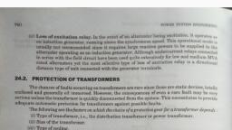
Fatima Michael College of Engineering & Technology, , Factors in choosing Protective Gear, for a Transformer, Type of Transformer, Size of the Transformer, Type of Cooling, System where used, Importance of service for which it is required, , Fatima Michael College of Engineering & Technology
Page 211 :
Fatima Michael College of Engineering & Technology, , Transformer Relaying Scheme, , Fatima Michael College of Engineering & Technology
Page 212 :
Fatima Michael College of Engineering & Technology, , Buchholz Protection, Also known as gas accumulator relay, commonly used on, all oil-immersed transformer provided with conservator., Working Principle:, Whenever a fault occur inside the transformer, the, oil of the tank gets overheated and gases are generated., The heat generated by the high local current causes the, transformer oil to decompose and produce gas which can, be used to detect the winding faults, , Fatima Michael College of Engineering & Technology
Page 213 :
Fatima Michael College of Engineering & Technology, , Buchholz Protection, , Fatima Michael College of Engineering & Technology
Page 214 :
Fatima Michael College of Engineering & Technology, , Core-Balance Leakage Protection, This system is used to provide protection against earth, faults on high voltage winding. When earth fault occurs,, the sum of the three currents is no longer zero and a, current is induced in the secondary of the CT causing, the trip relay to operate and isolate the transformer from, the bus-bars., , Fatima Michael College of Engineering & Technology
Page 215 :
Fatima Michael College of Engineering & Technology, , Fatima Michael College of Engineering & Technology
Page 216 :
Fatima Michael College of Engineering & Technology, , Combined Leakage and Overload, Protection, The core-balance protection cannot provide protection, against overload. It is usual practice to provide combined, leakage and overload protection for transformer. The, earth relay has low current setting and operates under, earth faults only. The overload relays have high current, setting and are arrange to operate against faults, between the phases, , Fatima Michael College of Engineering & Technology
Page 217 :
Fatima Michael College of Engineering & Technology, , In this system, two overload relay and one earth relay, , are connected. The two overload relays are sufficient to, protect against phase to phase faults. The trip contacts, of overload relays and earth fault relay are connected, in parallel. Therefore the energizing of either one of, them, the circuit breaker will tripped., , Fatima Michael College of Engineering & Technology
Page 218 :
Fatima Michael College of Engineering & Technology, , Transformer Protection, Overheating, Normal maximum working temp. = 95 °C, 8-10 °C rise will halve the life of the transformer., , Overcurrent, Fuses for distribution transformer, Overcurrent relaying for 5MVA and above, Characteristics:, – Must be below the damage curve, – Must be above magnetizing inrush, Fatima Michael College of Engineering & Technology
Page 219 :
Fatima Michael College of Engineering & Technology, , Conclusion, Open-circuit faults, earth faults, phase-to-phase faults,, , inter-turn faults and overheating are the fault that are, likely occur in a transformer, Relays control output circuits of a much higher, power., Safety is increased, Protective relays are essential for keeping faults in the, system isolated and keep equipment from being, damaged., , Fatima Michael College of Engineering & Technology
Page 220 :
Fatima Michael College of Engineering & Technology, , Fatima Michael College of Engineering & Technology
Page 221 :
Fatima Michael College of Engineering & Technology, , Introduction, , , , , , , Generator is the electrical end of a turbo-generator set., Without Generator, turbine/boiler/any Power Plant Equipment, is meaningless. Generator is the most precious/valuable, equipment in PP which actually converts the mechanical, energy of turbine into electricity. So, Generator should be, protected from faults occurring within generator and also from, external faults/abnormal operating condition in the GRID, which affected the generator., Various relays/devices are used to detect the abnormalities in, operations and whenever fault conditions appear, they can give, warning alarms to the operators or trip the unit automatically., Generally automatic tripping are provided if the time for, operator to take corrective action is less or the fault is likely to, cause serious damage to the unit., Fatima Michael College of Engineering & Technology
Page 222 :
Fatima Michael College of Engineering & Technology, , FAULT IN THE GENERATOR, , , , , Stator, Phase to Phase fault., Inter – turn fault, Earth fault (80% & 100%), Rotor, Rotor E/F – Two stage relay: a) Alarm b) Trip, Over voltage in the rotor., , Fatima Michael College of Engineering & Technology
Page 223 :
Fatima Michael College of Engineering & Technology, , ABNORMAL OPERATING, CONDITIONS:, Which affects the generator, Negative Phase sequence, Loss of Excitation, Over fluxing protection, Reverse power, Over-speeding, Pole slipping/ Out of Step, Fatima Michael College of Engineering & Technology
Page 224 :
Fatima Michael College of Engineering & Technology, , PROTECTION CATEGORY, , , , , Complete Generator protection is divided into two category i.e., Class – A Protection, Class – B Protection, , , , CLASS – A: Protection where electrical isolation is an emergency.(, Insulation failure, ,S.C. etc.). Trip the GCB/Turbine/Boiler without, time delay or Generator automatic trips., , , , .Class – A follows;, Gen. Differential Prot., Gen. 100% E/F, Gen. SB E/F, Gen. NVD, Gen. O/C, Rotor 2nd stage E/F, Gen. Brg. Temp. high, , , , , , , , , , Fatima Michael College of Engineering & Technology
Page 225 :
Fatima Michael College of Engineering & Technology, , CLASS - B, , , CLASS – B: Protection where external, abnormalities come into picture, such as temp., rise. Generator trips through LFP relay., , , , Class – B follows;, Reverse power, Voltage restrained O/C, Thermal O/C, Negative Phase sequence, U/V and O/V 2nd stage, Over fluxing/ Field failure, Gen. over/under frequency., , , , , , , , , , Fatima Michael College of Engineering & Technology
Page 226 :
Fatima Michael College of Engineering & Technology, , EARTH FAULT:, , , , , , , , , When fault current flows through earth return path,, the fault is called Earth Fault., Possible causes are ;(a) Insulation failure, (b) due to, over heating (Failure of water/air circulation through, stator conductor)., Earth fault may occur between any phase conductor, and core., It is usually practice to limit the earth fault current to, avoid extensive damage to the stator core., Fatima Michael College of Engineering & Technology
Page 227 :
Fatima Michael College of Engineering & Technology, , STAND BY EARTH FAULT:, , , , , , , , This protection is practically protects 95% of, generator winding. Therefore a current setting of, 5% of in to be set., E/F current is generally limited to about 15/20Amps., Earth fault current of even 100A for few seconds can, cause external damage. So the earth fault is restricted, to 100Amps. By providing NGR of 63.5 ohms at, 11KV Voltage Level., This is a Back-Up protection., Fatima Michael College of Engineering & Technology
Page 228 :
Fatima Michael College of Engineering & Technology, , Fatima Michael College of Engineering & Technology
Page 229 :
Fatima Michael College of Engineering & Technology, , 100% STATOR EARTH FAULT:, , , , , , , In this protection, where neutral voltage measurement is made, at generator terminals, (By Broken Delta), the third harmonic, voltage element is used., First earth fault very near to neutral produces negligible, current as driving voltage is nearly zero. But if a 2nd earth, fault occurs at machine terminal, line to ground fault is not, limited by NGR. The resulting fault current can be high., Hence, the 1st E/F very near to neutral has to be detected early, and isolated., All generators produce continuous current of 3rd harmonic, voltage. Under normal condition, 3rd harmonic voltage is, present. If there is a fault near neutral, the amount of 3rd, harmonic voltage comes down and this is used for detection., Fatima Michael College of Engineering & Technology
Page 230 :
Fatima Michael College of Engineering & Technology, , STATOR EARTH FAULT PROTECTION, Generator, , Red, Yellow, Blue, , Relay, , CT, Neutral Earth, Resistance, , Fatima Michael College of Engineering & Technology
Page 231 :
Fatima Michael College of Engineering & Technology, , ROTOR EARTH FAULT:, , , , , Since rotor circuits operate ungrounded, a single earth fault is, caused by insulation failure due to moisture, ageing of, insulation or vibration of rotor etc. But existence of single, ground fault increases the chance of a second ground fault., The occurrence of second earth fault can cause fault current, flows. This results unsymmetrical flux distribution. The air, gap flux is badly distorted. The rotor is displaced enough to, rub stator leading to severe vibrations and can damage the, bearing., Although a machine can continuously run on a single earth, fault but second rotor earth fault, if allowed to occur,, should be detected immediately and generator should be, tripped., Fatima Michael College of Engineering & Technology
Page 232 :
Fatima Michael College of Engineering & Technology, , Fatima Michael College of Engineering & Technology
Page 233 :
Fatima Michael College of Engineering & Technology, , DIFFERENTIAL PROTECTION, , , , , , , Differential protection is very reliable method for stator, winding phase to phase fault. In this, currents on both, sides of the generator are compared., Under normal condition or for a fault outside of the, protected zone, current i1s is equal to current i2s., Therefore, the currents in the CTs secondaries are also, equal, i1s=i2s and no current flows through the current, relays., If a fault develops inside of the protected zone, current i1s, and i2s are no longer equal, therefore i1s and i2s are not, equal and therefore a current flowing in the current relay., , Fatima Michael College of Engineering & Technology
Page 234 :
Fatima Michael College of Engineering & Technology, , Fatima Michael College of Engineering & Technology
Page 235 :
Fatima Michael College of Engineering & Technology, , Negative Phase Sequence Protection:, , , , , , , , , When the generator is connected to a balanced load, the phase currents are, equal in magnitude and displaced electrically by 120°. The ATs wave, produced by the stator currents rotate synchronously with the rotor and no, eddy currents are induced in the rotor parts., If there is an unbalanced loading of the generator, and then the stator, currents have a –ve sequence component. The stator field due to these –ve, sequence currents rotates at synchronous speed but in a direction opposite, to the direction of the field structure on the rotor. Thus, the –ve sequence, stator armature mmf rotates at a speed –Ns, while the rotor field speed is, +Ns. There is a relative velocity of 2Ns between the two., These causes double frequency currents, of large amplitude to be induced, in the rotor conductors and iron part. So both the eddy currents as well as, the hystersis losses increase due to these double frequencies induced, currents in the rotor., Unbalanced loading affects ;(a) Rotor heating (b) Severe vibration &, heating of stator., , Fatima Michael College of Engineering & Technology
Page 236 :
Fatima Michael College of Engineering & Technology, , FIELD FAILURE PROTECTION:, , , , , , , , , , , , , , Acts as an Induction Generator., Possible Causes;, AVR Fault, Tripping of Field C.B., Open circuit or Short circuit occurring in the D.C. circuit., PMG failure, In normal condition, generator when running shares the reactive demand of the, system. If excitation fails, synchronous generator runs at a super-synchronous, speed, draws reactive power from the power system instead of supplying the Qe., In case, the other generators can’t meet the requirement of reactive power, this, shall result in large voltage drop which may ultimately result in instability., In this case, slip becomes –Ve result in slip frequency currents. Rotor gets, heated up due to induced currents in the rotor winding, core or damage the, winding if this condition is sustained. Stator heats up due to high stator currents, due to increase in reactive current from the system., By monitor (i) Field current, If, (ii) Phase current & voltage., , Fatima Michael College of Engineering & Technology
Page 237 :
Fatima Michael College of Engineering & Technology, , REVERSE POWER, PROTECTION:, , , , , , , , , , This protection is provided to protect against motoring., A generator is expected to supply active power to the connected system in, normal operation. If the generator primover fails, a generator that is connected, in parallel with another source of electrical supply will to begin to motor. This, reversal of power flow due to loss of prime mover can be detected by reverse, power element., Possible Causes:, When immediately after Synchronising control valves are not operated which, may happen due to some fault in the system or some delay by the operating, personnel., In case of sudden closure of stop valves or control valves when the generator, unit is still connected to the grid., Reverse power operation is harmful to the turbine since without steam flow in, the turbine. If the turbine continues to rotate, it will result in heating of turbine, blades due to churning action. However, the period for the turbine to overheat, may vary from a few seconds to minutes depending upon the turbine &, operating conditions., , Fatima Michael College of Engineering & Technology
Page 238 :
Fatima Michael College of Engineering & Technology, , Fatima Michael College of Engineering & Technology
Page 239 :
Fatima Michael College of Engineering & Technology, , OVER FLUXING PROTECTION:, , , , , , , , , , , , , , Fundamental Voltage- Flux relation:, V = 4.44 * N * f * ø, V/f = 4.44 * N * ø, = K * ø = K * B/A, V/f is a measure of flux in machine. That means, over fluxing can occur if the ratio, of voltage to frequency exceeds certain limits. High voltage or low frequency,, causing a rise in the V/f ratio, will produce high flux densities in the magnetic core, of the generator.This could cause the core of the machine to saturate & stray flux to, be induced in the unlamilated components that have not designed to carry flux. The, resulting eddy currents in the solid components e.g. core bolts & clamps and end of, core laminations can cause rapid overheating and damage., POSSIBLE CAUSES:, AVR failure, Load rejection under manual AVR control, Excessive excitation with Generator Offline., Decreasing Speed with operator tries to maintain rated stator voltage., AUTO to Manual transfer of AVR., , Fatima Michael College of Engineering & Technology
Page 240 :
Fatima Michael College of Engineering & Technology, , Fatima Michael College of Engineering & Technology
Page 241 :
Fatima Michael College of Engineering & Technology, , Various Industry Motor Applications, , , , , , , Fan, Blower, Pump, Compressor, Conveyor, Mixer, Cranes, , Fatima Michael College of Engineering & Technology
Page 242 :
Fatima Michael College of Engineering & Technology, , Types of Fault in Motors, External Fault, , Internal Fault, , Mechanical Load, , Bearing Failure, , Unbalance Supply, Voltage, , Winding phase and, earth fault, , Single Phasing, Phase Reversal, , Fatima Michael College of Engineering & Technology
Page 243 :
Fatima Michael College of Engineering & Technology, , Motor Protection Summary, THERMAL OVERLOAD, SHORT CIRCUIT, EARTH FAULT, UNBALANCE, BLOCKED ROTOR/STALLING PROTECTION, , Fatima Michael College of Engineering & Technology
Page 244 :
Fatima Michael College of Engineering & Technology, , Thermal Stress Causes Motor Failure, , Most of the motor failure contributors and failed motor components are related to motor overheating., Thermal stress potentially can cause the failure of all the major motor parts: Stator, Rotor, Bearings,, , Shaft and Frame., , Fatima Michael College of Engineering & Technology
Page 245 :
Fatima Michael College of Engineering & Technology, , Thermal Overload, •Consider a motor is as homogenous body, •Developing heat at constant rate., •Dissipating heat at constant rate., Heat disspation is proportional to temperature, rise, 2, –t/τ, T = KIR (1-e, , ), , Fatima Michael College of Engineering & Technology
Page 246 :
Fatima Michael College of Engineering & Technology, , Overload Protection - Thermal Model, • Main Factors and Elements Comprising, the Thermal Model are:, • Overload Pickup Level, • Overload Curve, • Cooling Time Constants, • Hot/Cold Stall Time Ratio, , Fatima Michael College of Engineering & Technology
Page 247 :
Fatima Michael College of Engineering & Technology, , THERMAL OVERLOAD cont……, SETTING CRITERIA : Thermal Element, , Motor running, Time in sec, , Starting, time :10s, , Sh or t- cir cuit, elem ent, , 293 A, , 1370 A, , 1720 A, , Current, (Amperes), , Fatima Michael College of Engineering & Technology
Page 248 :
Fatima Michael College of Engineering & Technology, , SHORT CIRCUIT PROTECTION, What, , is:-Motor short-circuit protection provided to cater for major stator winding faults, and terminal flashovers., Settings - Definite time over current relay, element, set to about 130% of motor starting, current and time delay set at 100ms., , Fatima Michael College of Engineering & Technology
Page 249 :
Fatima Michael College of Engineering & Technology, , Differential Protection, , • Differential protection may be considered the first, line of protection for internal phase-to-phase or, phase-to-ground faults., Summation method with six CTs:, • If six CTs are used in a summing, configuration, during motor starting, the, values from the two CTs on each phase, may not be equal as the CTs are not, perfectly identical and asymmetrical, currents may cause the CTs on each phase, to have different outputs., • The running differential delay can then be, fine tuned to an application such that it, responds very fast and is sensitive to low, differential current levels., , Fatima Michael College of Engineering & Technology
Page 250 :
Fatima Michael College of Engineering & Technology, , Ground Fault Protection, • What is:-A ground fault is a fault that, creates a path for current to flow from one, of the phases directly to the neutral through, the earth bypassing the load, • Ground faults in a motor occur:, • When its phase conductor’s insulation, is damaged for example due to voltage, stress, moisture or internal fault occurs, between the conductor and ground, • To limit :-the level of the ground fault, current connect an resistance known as, stablising resistance, , Fatima Michael College of Engineering & Technology
Page 251 :
Fatima Michael College of Engineering & Technology, , Phase Unbalance, What is:-In a balanced system the three line-neutral voltages are equal in, , magnitude and are 120 degrees out of phase with each other. Otherwise, the, system is unbalanced., , Positive Sequence, , Negative Sequence, , Fatima Michael College of Engineering & Technology
Page 252 :
Fatima Michael College of Engineering & Technology, , Main causes of current unbalance, •, •, •, •, , Blown fuses, Loose connections, Stator turn-to-turn faults, System voltage distortion and, unbalance, • Faults, Effects, • Motor winding overheating, • Excessive vibrations, • Cause motor insulation/winding/bearing, damage, , Fatima Michael College of Engineering & Technology
Page 253 :
Fatima Michael College of Engineering & Technology, , Motor Protection Stalling, What is:-It happens when motor circuits are energized, but motor rotor is not, rotating. It is also called locked rotor., Effects:, This will result in excessive currents flow given the same load. This will cause, thermal damage to the motor winding and insulation., , Fatima Michael College of Engineering & Technology
Page 254 :
Fatima Michael College of Engineering & Technology, , Motor Protection Stalling, Required for, Stalling during starting, , Stalling during running, , Cases, , Starting time < Stall withstand time, Stall withstand time< Starting time, , Fatima Michael College of Engineering & Technology
Page 255 :
Fatima Michael College of Engineering & Technology, , CURRENT RELAYS, IDMT RELAYS :, These relays have inverse characteristic and the operating time decreases as the, magnitude of current increases., GENERAL RELAY EQUATION :, , t = TMS X K/((I/In)^n – 1), t = RELAY OPERATING TIME, I = FAULT CURRENT, n = CONSTANT, K = CONSTANT, In = RELAY PLUG SETTING ( PICK UP ), TMS = TIME MULTIPLIER SETTING, , Fatima Michael College of Engineering & Technology
Page 256 :
Fatima Michael College of Engineering & Technology, , Pilot Relays, Why needed:-Overcome diffculties of overcurrent, Relay ie, •Coordination, •Excessive fault clearance times, Principle:•Measurement of current at each end feeders, •Transmission of information, •No time and current gradation required, •Supervision facility., •Merz price Circulating scheme, , Fatima Michael College of Engineering & Technology
Page 257 :
Fatima Michael College of Engineering & Technology, , Fatima Michael College of Engineering & Technology
Page 258 :
Fatima Michael College of Engineering & Technology, , Bus Bar Protection, Bus Differential: Current into bus must equal, current out of bus, , Fatima Michael College of Engineering & Technology
Page 259 :
Fatima Michael College of Engineering & Technology, , Bus Fault, , Bus Protection, , Fatima Michael College of Engineering & Technology
Page 260 :
Fatima Michael College of Engineering & Technology, , Busbar Protection, Typical Bus Arrangements:, Single bus, Double bus, double breaker, Breaker-and-a-half, Main and transfer buses with single breaker, Ring bus, , Fatima Michael College of Engineering & Technology
Page 261 :
Fatima Michael College of Engineering & Technology, , Busbar Protection, Bus differential connection (single-bus), , 87B, 86B, TRIPS AND LOCKSOUT ALL BREAKERS, CONNECTED TO BUS, , BUS, , NOTE: All CTs connected to the bus differential, must have same ratios., , Fatima Michael College of Engineering & Technology
Page 262 :
Fatima Michael College of Engineering & Technology, , Busbar Protection, Bus differential connection (double-bus, double-breaker), TRIPS AND LOCKSOUT ALL BREAKERS, CONNECTED TO, BUS 1, , 87B, , 87B, , 86B, , 86B, TRIPS AND LOCKSOUT ALL BREAKERS, CONNECTED TO, BUS 2, , BUS 1, , BUS 2, , Fatima Michael College of Engineering & Technology
Page 263 :
Fatima Michael College of Engineering & Technology, , Busbar Protection, Bus differential connection (breaker-and-a-half), 86B, TRIPS AND, LOCKS-OUT ALL, BREAKERS, CONNECTED TO, BUS 1, , 87B, , 87B, 86B, TRIPS AND, LOCKS-OUT ALL, BREAKERS, CONNECTED TO, BUS 2, , BUS 1, , BUS 2, , Fatima Michael College of Engineering & Technology
Page 264 :
Fatima Michael College of Engineering & Technology, , Busbar Protection, Bus differential connection (main and transfer bus), , BUS 1, BUS 2, , TRIPS AND LOCKS-OUT ALL, BREAKERS CONNECTED TO, BUS 1, , 86B1, 87B1, 87B2, BUS IMAGING, RELAY, , 86B2, TRIPS AND LOCKS-OUT ALL, BREAKERS CONNECTED TO BUS, 2, , Fatima Michael College of Engineering & Technology
Page 265 :
Fatima Michael College of Engineering & Technology, , Busbar Protection, Bus differential connection (ring bus), , NOTE: No bus differential protection is needed. The, busses are covered by line or transformer protection., , Fatima Michael College of Engineering & Technology
Page 266 :
Fatima Michael College of Engineering & Technology, , Busbar Protection, Two Busbar Protection Schemes:, Low Impedance - using time overcurrent relays, inexpensive but affected by CT saturation., low voltage application; 34.5kV and below, , • High Impedance - using overvoltage relays (this, , scheme loads the CTs with a high impedance to force the, differential current through the CTs instead of the relay, operating coil.), expensive but provides higher protection security., 115kV and above voltage application or some 34.5kV, bus voltages which require high protection security., , Fatima Michael College of Engineering & Technology
Page 267 :
Fatima Michael College of Engineering & Technology, , Fatima Michael College of Engineering & Technology
Page 268 :
Fatima Michael College of Engineering & Technology, , Transmission Line Protection, •, •, •, •, , Distance Protection, Over Current Protection, Differential Protection., Main and Back up Protection, , Fatima Michael College of Engineering & Technology
Page 269 :
Fatima Michael College of Engineering & Technology, , Distance Relay Protection, • The basic principle is that the apparent impedance, seen by the relay reduces drastically in case of line, fault., • If the ratio of apparent impedance to the positive, sequence impedance is less than unity, it indicates a, fault., • This protection scheme is inherently directional., • Impedance relay and Mho relay use this principle., , Fatima Michael College of Engineering & Technology
Page 270 :
Fatima Michael College of Engineering & Technology, , Distance Relay Protection, , Fatima Michael College of Engineering & Technology
Page 271 :
Fatima Michael College of Engineering & Technology, , Over Current Relay Protection, Principle of Over current Protection, • When the current in a system exceeds a, predetermined value, it indicates the presence of a, fault., • Relaying decision is based solely on the magnitude of, current., • Over current relaying and fuse protection uses this, principle, • Used in radial distribution systems., Fatima Michael College of Engineering & Technology
Page 272 :
Fatima Michael College of Engineering & Technology, , Over Current Relay Protection, , Fatima Michael College of Engineering & Technology
Page 273 :
Fatima Michael College of Engineering & Technology, , Directional Over Relay, Protection, • Directional Over current Protection Uses both, magnitude of current and phase angle, information for decision making., • Used in radial distribution systems with source, at both ends, , Fatima Michael College of Engineering & Technology
Page 274 :
Fatima Michael College of Engineering & Technology, , Directional Over Relay, Protection, , Fatima Michael College of Engineering & Technology
Page 275 :
Fatima Michael College of Engineering & Technology, , Differential Relay Protection for, Transmission Line, • By comparing the two currents either in, magnitude or in phase or in both, fault can be, determined., • Its implementation requires a communication, channel., • It is extremely accurate., • Its zone is demarkated by CTs, , Fatima Michael College of Engineering & Technology
Page 276 :
Fatima Michael College of Engineering & Technology, , Differential Relay Protection, for Transmission Line, , Fatima Michael College of Engineering & Technology
Page 277 :
Fatima Michael College of Engineering & Technology, , Fatima Michael College of Engineering & Technology
Page 278 :
Fatima Michael College of Engineering & Technology, , Current and Voltage Transformers, in Protective Relaying System, Protective Relays in A.C. Power Systems are connected, from the secondary circuits of C.T. & P.T., Current Transformers : C.T. are used for measurement, and Protection. Its step down the current from high value, to low current value. Their ratio is constant for given, range of Primary & Secondary Current., Potential Transformer : P.T. are used for measurement, and Protection. Its step down the high voltage to low, voltage value. The ratio is constant for given range of, Primary and Secondary voltage., , Fatima Michael College of Engineering & Technology
Page 279 :
Fatima Michael College of Engineering & Technology, , Current Transformers, Current Transformer (CT) :, A device which transforms the current on the power system, from large primary values to safe secondary values. The, secondary current will be proportional (as per the ratio) to the, primary current., , Fatima Michael College of Engineering & Technology
Page 280 :
Fatima Michael College of Engineering & Technology, , Potential Transformers, Potential Transformer (PT):, A device which transforms the, voltage on the power system from, primary values to safe secondary, values, in a ratio proportional to the, primary value., , Fatima Michael College of Engineering & Technology
Page 281 :
Fatima Michael College of Engineering & Technology, , UNIT, , 4, , Theory of circuit, interruption, Fatima Michael College of Engineering & Technology
Page 282 :
Fatima Michael College of Engineering & Technology, , UNIT 4 Syllabus, , Fatima Michael College of Engineering & Technology
Page 283 :
Fatima Michael College of Engineering & Technology, , Fatima Michael College of Engineering & Technology
Page 284 :
Fatima Michael College of Engineering & Technology, , The ARC, The electric arc constitute a basic ,indispensable and active, element in the process of current interruption., 1.Basic theory of electric discharge, The conduction of electricity is through the gases or vapors, which contain positive and negative charge carriers and all types of, discharge involve the very fundamental process of production, ,movement & absorption of these carriers which is the mode of, carrying the current between the electrodes. The gas discharge, phenomena can broadly classified as:, a. The non-self sustained discharge, b. The self sustaining discharges, , Fatima Michael College of Engineering & Technology
Page 285 :
Fatima Michael College of Engineering & Technology, , Initiation of an Arc, , , , , By high voltage gradient, at the cathode resulting, into field emission., By increase of, temperature resulting, into thermo ionic, emission, , Fatima Michael College of Engineering & Technology
Page 286 :
Fatima Michael College of Engineering & Technology, , Maintenance of Arc, , , , , , , High temperature of the medium around the contacts, caused by high current densities, with high temp the, kinetic energy gained by moving electrons increased., The field strength or volt. gradient which increases, the kinetic energy of the moving electrons and, increases the chances of detaching electrons from, neutral molecule., An increase in mean free path-the distance through, which the electron moves freely., , Fatima Michael College of Engineering & Technology
Page 287 :
Fatima Michael College of Engineering & Technology, , Fatima Michael College of Engineering & Technology
Page 288 :
Fatima Michael College of Engineering & Technology, , Fatima Michael College of Engineering & Technology
Page 289 :
Fatima Michael College of Engineering & Technology, , Fatima Michael College of Engineering & Technology
Page 290 :
Fatima Michael College of Engineering & Technology, , Methods of Arc Extinction, , , High resistance method, , a. cooling of arc, b. increasing the arc length, c. reducing the cross section of arc, d. splitting of arc, , , , Low resistance or current zero interruption, , a. Lengthening of the gap, b.increasing the pressure in the vicinity of the arc, c. Cooling, d. Blast Effect, , Fatima Michael College of Engineering & Technology
Page 291 :
Fatima Michael College of Engineering & Technology, , Phenomenon of arc extinction, , , Energy Balance or Cassie Theory, This theory states that if the rate of heat, dissipation between the contacts is greater, then the rate at which heat is generated ,the, arc will be extinguished ,otherwise it will, restrike., , , , Recovery rate or Slepian’s Theory, , This theory states that if the rate at which, the ions and electrons combine to form or, replaced by neutral molecules., , Fatima Michael College of Engineering & Technology
Page 292 :
Fatima Michael College of Engineering & Technology, , Restriking Voltage & Recovery Voltage, , , The transient voltage which appears across the breaker contacts, at the instant of arc being extinguished is known as restriking, voltage., , , , The power frequency rms voltage ,which appears across the, breaker contacts after the arc is finally extinguished and, transient oscillation die out is called recovery voltage., , Fatima Michael College of Engineering & Technology
Page 293 :
Fatima Michael College of Engineering & Technology, , Arc Extinction, , Arc Voltage:, The Voltage drop, across the arc is, called Arc Voltage., , Fatima Michael College of Engineering & Technology
Page 294 :
Fatima Michael College of Engineering & Technology, , Arc Quenching: ( C.B ), •, , The Arc Produced not only delays the, current interruption process but it also generates, enormous heat which may cause damage to the, system or to the circuit breaker itself., •, Therefore main problem in a C.B is to, extinguish the arc within the shortest possible, time so the heat generated by it may not reach a, dangerous value., , Fatima Michael College of Engineering & Technology
Page 295 :
Fatima Michael College of Engineering & Technology, , ARC PHENOMENON, During arcing period, the current flowing between the, contacts depends upon the resistance. The greater, resistance smaller the current that flows between the, contacts., The arc resistance depends upon, i) Degree of ionisation ( Arc resistance increases with the, decrease in number of ionised particles b/w the contact ), ii) Length of Arc ( Arc resistance increases with the, length of arc ), iii) Cross section of Arc ( Arc resistance increases with, the decrease in X- section of the arc ), , Fatima Michael College of Engineering & Technology
Page 296 :
Fatima Michael College of Engineering & Technology, , The factors that are responsible for, maintenance of arc between the, contacts are:, i) Potential Difference between the, contacts., ii) ionised particles between the, contacts., , Fatima Michael College of Engineering & Technology
Page 297 :
Fatima Michael College of Engineering & Technology, , Methods of Arc Interruption, • There are two methods of Arc Interruption, or Extinction are, i) High resistance interruption, ii) Current zero interruption, High resistance interruption, The arc resistance can be increased by, cooling, lengthening, reducing x- section, and splitting the arc., Fatima Michael College of Engineering & Technology
Page 298 :
Fatima Michael College of Engineering & Technology, , It is employed for low power AC and DC, circuit breakers., Current zero interruption, There are two theories to explain the zero, current interruption of the arc., i) Recovery rate theory(Slepain’s Theory), ii) Energy balance theory(Cassie’s Theory), , Fatima Michael College of Engineering & Technology
Page 299 :
Fatima Michael College of Engineering & Technology, , Recovery rate theory, , Fatima Michael College of Engineering & Technology
Page 300 :
Fatima Michael College of Engineering & Technology, , Energy balance theory, , Fatima Michael College of Engineering & Technology
Page 301 :
Fatima Michael College of Engineering & Technology, , Arc Extinction in oil Circuit Breaker, In case of oil circuit breaker the, opening of contact which heats the oil, surrounds the contact due to arc which, causes hydrogen gas bubble to evolve, and its removes the heat from the surface., If the rate of heat removal is faster than its, generation then the arc is extinguished., , Fatima Michael College of Engineering & Technology
Page 302 :
Fatima Michael College of Engineering & Technology, , Arc interruption, (or) Extinction, methods, Fatima Michael College of Engineering & Technology
Page 303 :
Fatima Michael College of Engineering & Technology, , Fatima Michael College of Engineering & Technology
Page 304 :
Fatima Michael College of Engineering & Technology, , a) Lengthening the arc : by arc runners, , Fatima Michael College of Engineering & Technology
Page 305 :
Fatima Michael College of Engineering & Technology, , b) Splitting the Arc:, , In this method the arc is elongated and splitted by arc splitters. These are, made with plates of resin bonded fiber gas. These are placed perpendicular, to arc and arc is pulled into them by electromagnetic forces., , Fatima Michael College of Engineering & Technology
Page 306 :
Fatima Michael College of Engineering & Technology, , c) Cooling of Arc :, It causes recombination of ionized particles. Cooling remove the heat from, the Arc. Efficient cooling may be obtained by gas blast directed along Arc ., , 2) Low resistance (or) current zero interruption:, This method is used for Arc Extinction in A.C circuit breakers. In this method, the resistance kept low until current is zero., , Fatima Michael College of Engineering & Technology
Page 307 :
Fatima Michael College of Engineering & Technology, , The rapid increase of dielectric strength of the medium near current zero, can be achieved by, 1)Lengthening of Arc, 2)Cooling, 3)Blast effect, , Fatima Michael College of Engineering & Technology
Page 308 :
Fatima Michael College of Engineering & Technology, , Refer Book, Fatima Michael College of Engineering & Technology
Page 309 :
Fatima Michael College of Engineering & Technology, , Fatima Michael College of Engineering & Technology
Page 310 :
Fatima Michael College of Engineering & Technology, , How is dc breaking done?, The contacts of the DC breaker separate and the, arc is transferred from contacts to the runners, where it rises upwards and extinguishes on its, own., , Fatima Michael College of Engineering & Technology
Page 311 :
Fatima Michael College of Engineering & Technology, , Drawbacks of HVDC circuit breaking, , , , , The amount of energy to be dissipated during the, short interval of breaking is very high as, compared to the conventional a.c circuit breakers, , The natural zero current does not occur as in the, case of a.c cb, resistance switching and the, efficient cooling by forcing the liquid or air blast, are used to dissipate the high amount of energy., , Fatima Michael College of Engineering & Technology
Page 312 :
Fatima Michael College of Engineering & Technology, , SIMPLE D.C CIRCUIT, , •B, circuit breaker., •Assuming CB “B” breaks the current I, (=E/R), , Fatima Michael College of Engineering & Technology
Page 313 :
Fatima Michael College of Engineering & Technology, , ARC CHARACTERISTICS, , Fatima Michael College of Engineering & Technology
Page 315 :
Fatima Michael College of Engineering & Technology, , Basic requirement, Progressive lengthening of arc is a basic, requirement of dc circuit breakers., , Fatima Michael College of Engineering & Technology
Page 316 :
Fatima Michael College of Engineering & Technology, , In designing an HVDC circuit breaker there are, there main problems to be solved, , How to produce a current zero?, How to prevent restriking?, How to dissipate the stored energy?, , , Producing current zero, This approach involves changing the form of arc, current by commutation principle, Quenching gear of well proven HVAC ckt breaker, Principle of oscillatory circuit, , Fatima Michael College of Engineering & Technology
Page 317 :
Fatima Michael College of Engineering & Technology, , Prevention of restrikes, To produce a good ionizing arc the space between two, walls of arc chute can be narrowed to restrict the arc, At the same time it can be broken into number of arcs, by inserting a grating of vertical metal plane, Dissipation of stored energy, A protective spark gap can be used across the CB to, reduce the size of the commuting capacitor., It will keep the abnormal voltage produced at the, switching time below the undesired level, By means of high frequency currents the spark gap, acts as an energy dissipating device, , Fatima Michael College of Engineering & Technology
Page 318 :
Fatima Michael College of Engineering & Technology, , Interruption of, capacitive current, Fatima Michael College of Engineering & Technology
Page 319 :
Fatima Michael College of Engineering & Technology, , INTERRUPTION OF CAPACITIVE CURRENT, Effect:, The interruption of capacitive current produces, high voltage transients across the gap of the, circuit breaker., When?, This occurs when an unloaded long transmission, line or a capacitor bank is switched off., , Fatima Michael College of Engineering & Technology
Page 320 :
Fatima Michael College of Engineering & Technology, , Fatima Michael College of Engineering & Technology
Page 321 :
Fatima Michael College of Engineering & Technology, , •Considering a electrical circuit of a simple power system, , •C, •C L, , stray capacitance of the circuit breaker, line capacitance, , Fatima Michael College of Engineering & Technology
Page 322 :
TRANSIENT VOLTAGE ACROSS THE GAP, Fatima Michael College of Engineering & Technology, , OF THE CIRCUIT BREAKER WHEN THE, , CAPACITIVE CURRENT IS INTERRUPTED, , Fatima Michael College of Engineering & Technology
Page 323 :
Fatima Michael College of Engineering & Technology, , At the instant M, , The capacitive current is 0., System voltage is maximum, , , , , , If interruption occurs, , Capacitor CL remains charged at the maximum value of, system voltage., , After the instant M, , , Voltage across the breaker gap is, the difference of Vc and VcL., , Fatima Michael College of Engineering & Technology
Page 324 :
Fatima Michael College of Engineering & Technology, , At the instant N, The voltage across the gap is twice the maximum, Value of Vc., , If the breaker restrikes, , The voltage across the gap become partially zero., Voltage falls from 2Vcmax to zero., A severe high frequency oscillation occurs, (about the point S), Interrupted again.( if restriking current=0), The capacitor CL at the voltage -3emax., , , Fatima Michael College of Engineering & Technology
Page 325 :
Fatima Michael College of Engineering & Technology, , At the instant P, The system voltage reaches its positive, maximum.(point T), Voltage across the gap becomes 4emax., The capacitive current reaches zero again and there, may be an interruption., The transient voltage oscillates between -3emax and, +5emax. (point P—Q), , , , Thus voltage across the gap goes on increasing, , Fatima Michael College of Engineering & Technology
Page 326 :
Fatima Michael College of Engineering & Technology, , Fatima Michael College of Engineering & Technology
Page 327 :
Fatima Michael College of Engineering & Technology, , UNIT, , U, , 5, , B, , K, , Fatima Michael College of Engineering & Technology
Page 328 :
Fatima Michael College of Engineering & Technology, , UNIT 5 Syllabus, , Types of circuit breakers, 1. Air Blast circuit breaker, 2. Vacuum circuit breaker, 3. Oil circuit breaker, 4. SF6 circuit breaker, Comparison of Airblast,Vacuum,Oil,SF6, Testing of circuit breakers., Fatima Michael College of Engineering & Technology
Page 329 :
Fatima Michael College of Engineering & Technology, , Types Of Circuit Breakers, Oil Circuit Breakers, Vacuum Circuit Breakers, Air Blast Circuit Breakers, SF6 Circuit Breakers, , Fatima Michael College of Engineering & Technology
Page 330 :
Fatima Michael College of Engineering & Technology, , 1., , OIL CIRCUIT BREAKER, , It is designed for 11kv-765kv., These are of two types, • BOCB (Bulk oil Circuit Breaker), • MOCB (Minimum oil Circuit Breaker), , The contacts are immersed in, , oil bath., Oil provides cooling by, hydrogen created by arc., It acts as a good dielectric, medium and quenches the arc., Fatima Michael College of Engineering & Technology
Page 331 :
Fatima Michael College of Engineering & Technology, , Advantages:, Oil has good dielectric strength., Low cost., Oil is easily available., It has wide range of breaking capability., , Disadvantages:, Slower operation , takes about 20 cycles for arc, , quenching., It is highly inflammable , so high risk of fire., High maintenance cost., Fatima Michael College of Engineering & Technology
Page 332 :
Fatima Michael College of Engineering & Technology, , 2. VACCUM CIRCUIT BREAKER, It is designed for medium voltage, , range (3.3-33kv)., This consists of vacuum of pressure, (1*10-6) inside arc extinction chamber., The arc burns in metal vapour when, the contacts are disconnected., At high voltage , it’s rate of dielectric, strength recovery is very high., Due to vacuum arc extinction is very, fast., The contacts loose metals gradually, due to formation of metal vapours., , Fatima Michael College of Engineering & Technology
Page 333 :
Fatima Michael College of Engineering & Technology, , Advantages:, Free from arc and fire hazards., Low cost for maintenance & simpler mechanism., Low arcing time & high contact life., Silent and less vibrational operation., Due to vacuum contacts remain free from corrosion., No byproducts formed., , Disadvantages:, High initial cost due to creation of vacuum., Surface of contacts are depleted due to metal vapours., High cost & size required for high voltage breakers., Fatima Michael College of Engineering & Technology
Page 334 :
Fatima Michael College of Engineering & Technology, , 3. AIR BLAST CIRCUIT BREAKERS, This operates using high velocity blast of air which, quenches the arc., It consists of blast valve , blast tube & contacts., Blast valve contains air at high pressure., Blast tube carries the air at high pressure & opens the, moving contact attached to spring., There is no carbonization of surface as in VCB., Air should be kept clean & dry to operate it properly., Fatima Michael College of Engineering & Technology
Page 335 :
Fatima Michael College of Engineering & Technology, , Fatima Michael College of Engineering & Technology
Page 336 :
Fatima Michael College of Engineering & Technology, , Advantages:, High speed operation as compared to OCB., Ability to withstand frequent switching., Facility for high speed reclosure., Less maintenance as compared to OCB., , Disadvantages:, Little moisture content prolongs arcing time., Pressure should be checked frequently for frequent, , operation., Risk of fire hazards due to over voltages., It can’t be used for high voltage operation due to, prolonged arc quenching., Fatima Michael College of Engineering & Technology
Page 337 :
Fatima Michael College of Engineering & Technology, , 4. SF6 CIRCUIT BREAKERS, It contains an arc interruption chamber containing SF6 gas., In closed position the contacts remain surrounded, by SF6 gas at a pressure of 2.8 kg/cm2 ., During opening high pressure SF6 gas at 14 kg/cm2 from its, reservoir flows towards the chamber by valve mechanism., SF6 rapidly absorbs the free electrons in the arc path to, form immobile negative ions to build up high dielectric, strength., It also cools the arc and extinguishes it., After operation the valve is closed by the action of a set of, springs., Absorbent materials are used to absorb the byproducts and, moisture., Fatima Michael College of Engineering & Technology
Page 338 :
Fatima Michael College of Engineering & Technology, , Fatima Michael College of Engineering & Technology
Page 339 :
Fatima Michael College of Engineering & Technology, , Advantages:, Very short arcing period due to superior arc quenching, , property of SF6 ., Can interrupt much larger currents as compared to other, breakers., No risk of fire., Low maintenance, light foundation., No over voltage problem., There are no carbon deposits., , Disadvantages:, SF6 breakers are costly due to high cost of SF6., SF6 gas has to be reconditioned after every operation of the, breaker, additional equipment is required for this purpose., Fatima Michael College of Engineering & Technology
Page 340 :
Fatima Michael College of Engineering & Technology, , Comparison of Circuit Breakers, , Fatima Michael College of Engineering & Technology
Page 341 :
Fatima Michael College of Engineering & Technology, , CONCLUSION:, Therefore, we conclude that circuit breaker is, the most essential part of the electrical, networks as it protects every device from, damage. It helps us to detect the fault and area, affected by it. Nowadays vacuum and SF6, circuit breakers are widely used due to their, reliable and fast operations., Fatima Michael College of Engineering & Technology
Page 342 :
Fatima Michael College of Engineering & Technology, , Testing of circuit, breaker, Fatima Michael College of Engineering & Technology
Page 343 :
Fatima Michael College of Engineering & Technology, , Why "Testing of Circuit Breaker" is Necessary?, A Circuit Breaker should be capable of carrying, making, and, breaking under normal and abnormal conditions. In any power, system circuit breaker has to withstand power frequency over, voltages and transient over voltages due to switching and, lightning., The performance of a circuit breaker under normal and abnormal, conditions can be verified by performing different type of tests, on circuit breakers. The main purpose of testing of circuit, breakers is to confirm if circuit breaker is able to work on, particular voltage and current ratings or not., , Fatima Michael College of Engineering & Technology
Page 344 :
Fatima Michael College of Engineering & Technology, , There are mainly two tests classified:, 1) Type test, 2) Routine Test, , 1) Type Tests:, , The purpose of type tests is to prove design features and, the quality of circuit breaker. Type tests are not conducted, on each circuit breaker. This is done to prove the, capabilities and to confirm the rated characteristics of the, circuit breakers., , Fatima Michael College of Engineering & Technology
Page 345 :
Fatima Michael College of Engineering & Technology, , 2)Routine Tests:, , Routine test is performed before circuit, breaker dispatch to ensure the product. This, gives result about defects in materials and, construction of circuit breaker. We can, check quality of material of circuit breaker, by performing Routine Test., , Fatima Michael College of Engineering & Technology
Page 346 :
Fatima Michael College of Engineering & Technology, , Mechanical endurance tests, Thermal tests, Dielectric tests, Measurement of resistance of the main circuits, Short Circuit tests, , Fatima Michael College of Engineering & Technology
Page 347 :
Fatima Michael College of Engineering & Technology, , In this test, the C.B.. is open and closed 500 times or, other value as agreed to between the purchaser and the, supplier.the test are carried out without current through, the main circuit of the C.B.Out of the total number of, tests, 10% should be closed-open operation,that is with, the tripping,mechanism energized by the closing of, main contacts.During the tests,occasional lubrication,but, no mechanical adjustments are permissible.after the, tests,all parts including contacts should be in good, condition and there should be no permanent distortion, and undue wear of the parts., Fatima Michael College of Engineering & Technology
Page 348 :
Fatima Michael College of Engineering & Technology, , This test determines the maximum normal current that the, circuit breaker can carry without exceeding the maximum, allowable temperature rise.In this test the rated normal, current of normal frequency is passed through the current, carrying parts of circuit breaker., Method are recognized by Indian standards for measuring, temperature rise of parts:1) Thermometer method, 2) Thermocouple method, 3) Self resistance method, , Fatima Michael College of Engineering & Technology
Page 349 :
Fatima Michael College of Engineering & Technology, , 1) Breaking capacity Test:• Sequence of performing this tests is as follows: First of all,the master circuit breaker (MB)and the breaker under test, (TB)are closed., The s.c.current is passed by closing the make switch., The circuit breaker under test(TB) is opened to interrupt the s.c.current at, desired moment., , • The following measurements related to the breaking capacity, performance are taken from the oscillogram during the test: Symmetrical breaking current, Asymmetrical breaking current, Amplitude factor, Natural frequency of oscillations and RRRV(RATE OF RISE OF, RISTRIKING VOLTAGE), Fatima Michael College of Engineering & Technology
Page 350 :
Fatima Michael College of Engineering & Technology, , Sequence of Performing this test :-, , First of all,the master circuit breaker (MB)and the, make switch(MS) are closed., Then,the short circuit current is initiated by closing, the test breaker (TB)., The rated short circuit making current i.e.the peak, value of the first major loop of the short circuit, current envelope is measured from the oscillorgram., , Fatima Michael College of Engineering & Technology
Page 351 :
Fatima Michael College of Engineering & Technology, , 3) Short Time Withstand Current Capacity, •In this test, the rated short-time withstand current is, applied to the circuit breaker, under test for the specified duration of the time., •The rated short time withstand current is equal to be, rated short circuit breaking current and standard value, of rated duration of short circuit current is 1 second or 3, seconds., •The current is measured by taking an oscillograph of the, short circuit current wave., After the test, there should be no mechanical or insulation, damage and any contact welding., , Fatima Michael College of Engineering & Technology
Page 352 :
Fatima Michael College of Engineering & Technology, , REFERENCES, Fatima Michael College of Engineering & Technology
Page 353 :
Fatima Michael College of Engineering & Technology, , Book References:, Principles of power systems by V.K.Metha, Switchgear & Protection by Badri Ram, M.L. Soni, P.V. Gupta, V.S. Bhatnagar, A. Chakrabarti,, , ‘A Text Book on Power System Engineering’, R.K.Rajput, A Tex book of Power System Engineering., Laxmi Publications, Protection & Switchgear by U.A.Bakshi, Sunil S. Rao, ‘Switchgear and Protection’, Khanna, publishers., C.L. Wadhwa, ‘Electrical Power Systems’, Newage, International (P) Ltd., Fatima Michael College of Engineering & Technology
Page 354 :
Fatima Michael College of Engineering & Technology, , NPTEL References:, Power System Protection by S.A.Soman, , Department of Electrical Engineering IIT Bombay, , Fatima Michael College of Engineering & Technology