Page 1 :
Induction Heating, Definition: Induction Heating is a contactless electric heating process where, electrically conductive materials are heated by the principle of electromagnetic, induction. Here heat is generated within the conductive material without, making direct contact with the source., This high-frequency heating mechanism is sub-classified into two categories, namely,, 1. Induction heating, 2. Dielectric heating, These two methods of heating are crucially differentiated on the basis of the, material that gets heated up during the process. Basically, in the process of, induction heating, conducting materials like metal are heated up while in the, process of dielectric heating, insulating materials such as wood are heated., However, our concerning topic here is induction heating which we will discuss, in detail., Principle of Operation, , The operating principle in induction heating uses both the principle of, Faraday’s law of electromagnetic induction and the concept of Joule heating., Its operation is quite similar to the transformer that follows faraday’s law. In, transformers when primary winding is energized then the flow of current, through it leads to the generation of the alternating magnetic field. The created, magnetic flux when gets linked with the secondary winding generates emf, within the secondary winding, and current starts flowing through it. Here the, strength of the magnetic field shows dependency on the magnitude of the, applied electric field., It is to be noted here that no direct contact exists between the two coils, however, they are magnetically coupled which results in the flow of current, through the secondary winding of the transformer., Furthermore, according to the joule effect, when current flows through a, material then its internal resistance opposes the flow hence power is, dissipated in the form of heat.
Page 2 :
How Induction Heating takes place?, Before discussing the operation of induction heating you must note here that, the material that gets heated is known as a workpiece and the coil around the, workpiece that induces a current in it is called a workcoil., Induction heating takes place in a way that initially when a high-frequency, alternating current is passed through the coil (which acts as primary winding), then an alternating magnetic field surrounds the coil and flux is generated., This happens due to the law of electromagnetism. Now, the workpiece, (behaves as a single piece short-circuited secondary winding) is placed within, the coil as shown in the figure below:, , Then the magnetic field of the workcoil induces emf in the workpiece resulting, in the flow of eddy current through the workpiece. And this principle of, operation is similar to the one that takes place in transformers in accordance, with Faraday’s Law. The flow of eddy currents within the conductive, workpiece is in a loop as shown below:, , However, during the flow of current, there will be an opposing force to it i.e., finite, resistance and this leads to the dissipation of power in the form of heat through the, material and this effect is known as Joule Effect., , It is to be noted here that due to skin effect, during high-frequency operation,, the heat dissipation is confined only to the surface of the workpiece. In skin
Page 3 :
effect, the current is concentrated only to the surface of the workpiece. With, going deeper within the surface of the workpiece eddy current reduces. Thus,, the current density variation with respect to distance is represented below:, , The above graphical representation clearly shows that when the distance increases, then the current density gradually decreases., , Dielectric Heating, Dielectric Heating is a process of electric heating by which the temperature, of a dielectric (non-conducting) material is raised by the application of an, alternating electric field (high voltage ac signal). The increase in temperature, results in heating the substance which is in contact with the external field., Dielectric heating is sometimes called high frequency or radio-frequency, heating, capacitive heating. This process allows uniform heating of nonmetallic materials which are unable to conduct electricity., What is dielectric?, , Dielectrics are basically insulators that possess very poor conducting ability, relative to electric current. We know that every matter in this universe is, composed of molecules whose elemental particle is an atom., When an external field is not present then the polar molecules within a, material are randomly positioned within it. However, by applying an electric, field, the material gets polarized, this is because the dipole moments of polar, molecules get properly oriented. Now the question arises – how this, happens?, Basically, in conductors, the loosely bounded electrons drift through the, material when it is connected to the external electric field. However, this is not, the case with dielectrics as they do not have loosely bounded electrons or free, electrons for such actions. But here dielectric polarization occurs.
Page 4 :
Dielectric Polarization is nothing but the presence of polar molecules in the, proper orientation. To understand this, consider the figure shown below:, , Here there are two conductive plates separated by dielectric material in both images., The first one is unpolarized due to the absence of an electric field. However, in the, second figure, it is seen that the arrangement is subjected to an electric field, because of which there is a slight displacement of positive charges in the direction of, the electric field and negative charges in the opposite direction of it., The minute charge separation within the dielectric is known as polarization and this, leads to a reduction in the electric field within the dielectric., , Operating Principle of Dielectric Heating, The principle of operation of a dielectric heater is such that a non-conducting, material is present between two electrodes and an external electric field is applied, across these two electrodes. Basically, a wide range of frequency is provided to the, electrodes., •, , It is to be noted here that radio-frequency radiation is a form of, energy and not a form of heat. So, it requires material matter for, the conversion of heat from energy., , The dielectric material which is present between the two electrodes can be anything, such as wood, plastic, glass, etc. Though it is considered that a dielectric does not, allow the flow of electric current through it, practically, it is not possible., So, whenever these materials are provided with a high voltage alternating supply, then even minute motion of charged particles results in the flow of current which, leads to dielectric losses. This resultantly produces heat within the material., , Circuit Operation of Dielectric Heating, Till now we have got the idea that the sole purpose of a dielectric heater is to heat up, an insulating material. A dielectric heater is regarded as an electric heater as it, transforms electrical energy into heat., We have already discussed induction heating (which is also a type of electric, heating) in our previous content where the principle of electromagnetic induction is, used to heat up the magnetic material without making direct contact with the source.
Page 5 :
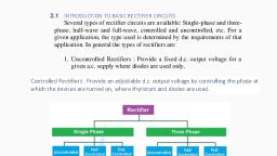
The figure below shows the circuit arrangement of a dielectric heater which is, formed by encapsulating an insulating material between two conducting plates, forming a parallel plate capacitor arrangement., , Here a very high-frequency ac voltage signal i.e., 20KV with frequency ranging, between 10 to 50 MHz is provided across the whole capacitive arrangement., , Single Phase Full Wave AC Voltage Controller:, A single phase full wave AC voltage controller comprises of two thyristor connected, in anti-parallel. The circuit diagram is shown in figure below., , The load is assumed resistive for the sake of simplicity. The input source is VmSinωt., For the positive half cycle of input source, thyristor T1 is forward biased and hence it, is able to conduct provided gate signal is applied. This means that T1 will remain, OFF until gate signal is applied. Now suppose, at some angle α (called the firing, angle), thyristor T1 is gated. As soon as T1 is fired / gated, it starts conducting and, hence, load gets directly connected to the source. This makes load voltage Vo =, VmSinα and load current Io = (VmSinα / R) at the instant T1 is fired. From wt = α to π,, the load voltage and current follows the input voltage waveform VmSinωt and, (VmSinωt / R) respectively., At wt = π, the load voltage becomes zero and current, also, becomes zero. Since,, thyristor T1 is reversed biased after ωt = π and current through it is zero, it gets, naturally commutated., At ωt = (π+α), forward biased thyristor T2 is gated. Hence, it conducts and, connected load to the source. The load voltage now follows the negative envelop of
Page 6 :
the AC input supply and the load current does the same. Thus, the root mean square, voltage may be controlled by having a control of firing angle. In this way, voltage, control is achieved in AC voltage Controller., The output waveform for load voltage & current is shown below., , It may be noted from the above waveform that the positive and negative half cycle of, the load voltage & current are identical. As a result, DC component is not introduced, in the supply and load circuit. This is the main advantage of single phase full wave, AC voltage controller., Single phase full wave AC voltage controller is also know as single phase, , bidirectional voltage controller. Let us now calculate the rms value of load voltage, and current., Single phase full wave voltage controllers are more suitable to practical circuits. It also, overcomes the problem of dc component which is present in supply and load circuit of half, wave voltage controller., , Single-Phase Semi Converter: Single Phase Semi Converter is, also known as a half-controlled converter. A single-phase half, controlled or semi converter utilizes SCRs(thyristor) and diodes to, convert AC power to DC power. Due to the utilization of diodes and, thyristors, it provides limited control over the level of DC output voltages., This section will discuss the single-phase semi-converter, its circuit, diagram, operation, waveform, average, and RMS output voltage, expression.
Page 7 :
Circuit Diagram of Single Phase Semi Converter, The figure below shows the circuit diagram of single phase semiconverter bridge circuit. The bridge circuit consists of two thyristors and, three diodes connected across an RLE load. Among these, two thyristors, (T1, T2) and two diodes(D 1, D2) are utilized in the bridge connection while, another diode (FD) is connected across the bridge circuit or load. The, free-wheeling diode(FD) finds its application in partially recovering the, energy stored in the inductor back to the load such that no energy is fed, back to the source., , The Waveform of Single-Phase Semi Converter, The figure below shows the waveform of a single-phase half-controlled, converter.
Page 8 :
Operation, The operation of a single-phase semi-converter is discussed based on, the above waveform for definite time intervals., , 1. At ωt=0 to ωt=π, During the interval of ωt =0 to ωt=α, thyristor T 1 and diode D 1 come into, operation. After ωt=0, thyristor T 1 becomes forward biased only if V msinωt, is greater than the load circuit emf E. The thyristor T 1 is then triggered at, ωt=α during which Vmsinα > E. When T 1 is triggered, it gets ON and the, load current i o flows through the RLE load through thyristor T 1 and diode, D1. The thyristor T 1 will be conducting from ωt =α to ωt=π., During ωt=α to ωt=π, the voltage waveform across the load terminal(V o), will be a replica of the source voltage(V S)., , 2. At ωt =π to ωt=2π, Just after the ωt=π i.e. ωt=πt, the supply voltage gets negative, this, causes thyristor T 1 to be reverse biased and it gets turned off. But on the, other side, this reversal of supply voltage at ωt=πt causes the, freewheeling diode (FD) to be forward biased. So now the load current, io gets transferred from T 1D1 to FD. As the freewheeling diode (FD) gets, forward biased, load terminals get short-circuited and the voltage, across the load(Vo) becomes zero., During this period, thyristor T 2 will be in reverse biased condition only if, the source voltage is greater than E. For ωt=π+α, source voltage (Vs) is, greater than E, and T 2 is triggered from FD to T 2 D2. After the T 2 gets, triggered, FD gets reverse biased., , 3. After ωt=2π, Just after ωt=2π, the thyristor T 2 gets reverse biased and is turned off, and on the other hand, FD gets forward biased, and load current i o gets, transferred to FD., This cycle continues until the AC supply is supplied to the circuit.
Page 9 :
Role of Freewheeling Diode, In the single-phase semi converter, we can observe from its waveform, that for time intervals α to π, T1 D1 conducts and for the interval (π+α) to, 2π, T2D2 conducts during which power is supplied from the source o the, RLE load., During this period, a certain amount of energy is stored by the, inductor(L), a definite amount in the load circuit emf, and in the resistor, (R), a certain amount of energy is dissipated in the form of heat., During the period π to π+α and 2π to 2π+α, the energy stored in the, inductor is partially fed back to the load circuit through the, freewheeling diode(FD). This energy that is being fed back to the load, circuit is partially dissipated in the resistor as heat and partially added, to the load circuit emf E., Hence, the freewheeling diode(FD) provides a freewheeling path for the, energy that is stored in the inductor during a certain interval to be fed, back to the load again., Power factor correction – What is it? Why is it required? How is it achieved?, , Power factor basics:, Power quality is essential for efficient equipment operation, and power factor, contributes to this., Power factor is the measure of how efficiently incoming power is used in an, electrical installation. It is the ratio of active to apparent power, when:, • Active Power (P) = the power needed for useful work such as turning a lathe, providing, light or pumping water, expressed in Watt or KiloWatt (kW), • Reactive Power (Q) = a measure of the stored energy reflected to the source which does, not do any useful work, expressed in var or Kilovar (kVAR), • Apparent Power (S) = the vector sum of active and reactive power, expressed in Volt, Amperes or in KiloVolt Amperes (kVA)
Page 10 :
The power triangle:, , Poor power factor (for example, less than 95%) results in more current being, required for the same amount of work., , Power factor correction, Power factor correction (PFC) aims to improve power factor, and therefore power, quality. It reduces the load on the electrical distribution system, increases energy, efficiency and reduces electricity costs. It also decreases the likelihood of instability, and failure of equipment., Power factor correction is obtained via the connection of capacitors which produce, reactive energy in opposition to the energy absorbed by loads such as motors,, locally close to the load. This improves the power factor from the point where the, reactive power source is connected, preventing the unnecessary circulation of, current in the network., , Determining the PFC required, The selection of PFC equipment should be done according to the following four-step, process, by persons with the relevant skills:, Step 1: Calculation of the required reactive power
Page 11 :
The objective is to determine the required reactive power (Qc (kvar)) to be installed,, in order to improve the power factor (cos φ) and reduce the apparent power (S)., , Qc can be determined from the formula Qc = P (tan φ – tan φ‘), which is deduced, from the diagram., • Qc = power of the capacitor bank in kVAr, • P = active power of the load in kW, • tan φ = tangent of phase shift angle before compensation, • tan φ’ = tangent of phase shift angle after compensation, , The parameters φ and tan φ can be obtained from billing data, or from direct, measurement in the installation., Step 2: Selection of the compensation mode, The location of low-voltage capacitors in an installation can either be central (one, location for the entire installation), by sector (section-by-section), at load level, or a, combination of the latter two., , In principle, the ideal compensation is applied at a point of consumption and at the, level required at any moment in time. In practice, technical and economic factors, govern the choice., The location is determined by:
Page 12 :
• the overall objective (avoiding penalties on reactive energy, relieving transformers or, cables, avoiding voltage drops and sags), • the operating mode (stable or fluctuating loads), • the foreseeable influence of capacitors on the network characteristics, • the installation cost, , Step 3: Selection of the compensation type, Different types of compensation should be adopted depending on the performance, requirements and complexity of control:, • Fixed, by connection of a fixed-value capacitor bank, • Automatic, by connection of a different number of steps, allowing adjustment of the, reactive energy to the required value, • Dynamic, for compensation of highly fluctuating loads, , Step 4: Allowance for operating conditions and harmonics, Operating conditions have a great impact on the life expectancy of capacitors, so the, following parameters should be taken into account:, • Ambient temperature (°C), • Expected over-current related to voltage disturbances, including maximum sustained, overvoltage, • Maximum number of switching operations per year, • Required life expectancy, , Some loads (variable speed motors, static converters, welding machines, arc, furnaces, fluorescent lamps, etc.) pollute the electrical network by reinjecting, harmonics. It is therefore also necessary to consider the effects of these harmonics, on the capacitors.