Notes of Plus Two Computer Science, Physics HSSRptr_Plus Two Physics-Focus Area 2022-Final.pdf - Study Material
Page 1 :
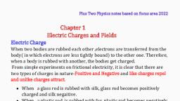
Plus Two Physics notes based on focus area 2022, , Chapter 1, Electric Charges and Fields, Electric Charge, When two bodies are rubbed each other ,electrons are transferred from the, body( in which electrons are less tightly bound) to the other one. Therefore,, when a body is rubbed with another, the bodies get charged., From simple experiments on frictional electricity, it is clear that there are, two types of charges in nature-Positive and Negative and like charges repel, and unlike charges attract., • When a glass rod is rubbed with silk, glass rod becomes positively, charged and silk negaitive., • When a plastic rod is rubbed with fur, plastic rod becomes negatively, charged and fur positive., , Gold Leaf Electroscope, , Dowloaded from www.hssreporter.com
Page 2 :
Properties of electric charges, 1.Electric charges are of two kinds – positive and negative., 2.Like charges repel and unlike charges attract each other., 3. Quantization of charge : According to quantisation of electric charge,, charge of a body is an integral multiple of a basic charge, which is the, electronic charge., Charge on a body, q=± ne ;, , where, n=1,2,3........., , e is the electronic charge. e=1.602 x 10⁻¹⁹ C, 4. Charge is conserved: It means that total charge of an isolated system, remains constant. It also implies that electric charges can neither be created, nor destroyed. If an object loses some charge, an equal amount of charge, appears somewhere else., 5.Charge is a scalar quantity., 6. Additivity of charge: The total charge on a surface is the algebraic sum of, individual charges present on that surface., If q1 , q 2 , q 3 ....................., q n are the charges on a surface, then total or net, charge,, 𝐪 = 𝐪𝟏 + 𝐪𝟐 + 𝐪𝟑 +.................. + 𝐪𝐧, , Example 1, How many electronic charges form 1 C of charge?, q=±ne,, 𝑞, n=, 𝑒, , n=, , 1, , 1.602 x 10⁻¹⁹, , =6.25 x10¹⁸, , Example 2, A comb drawn through person’s hair causes 1022 electrons to leave the, person’s hair and stick to the comb. Calculate the charge carried by the, comb., q= ne,, q = 1022 x 1.602 x 10−19 C, = −1.602 x 10³ C, As the comb gains electrons it gets negatively charged., Dowloaded from www.hssreporter.com
Page 4 :
Electric Field, Electric field is the region around a charge where its effect can be felt., Intensity of electric field at a point is the force per unit charge., , 𝐄=, , 𝐅, 𝐪, , Electric field due to a point charge, , 𝟏, , 𝐄 = 𝟒𝛑𝛆, , 𝟎, , 𝐪, 𝐫𝟐, , Electric field due to a system of charges, Electric field at a point due to a system of charges is the vector sum of the, electric fields at the point due to individual charges., , Dowloaded from www.hssreporter.com
Page 5 :
Electric Field Lines, An electric field line is a curve drawn in such a way that the tangent to it at, each point is in the direction of the net field at that point., (i)Electric Field lines tart from positive charge, end at negative charge., (ii) Electric field lines of a positive charge are radially outwards and that of, a negative charge is radially inwards, (iii) Electric field lines Do not form closed loops., (iv) In a charge free region Field lines are continuous., (v) Two field lines never intersect.( two directions for electric field is not, possible at a point), (vi) Field lines are parallel ,equidistant and in same direction in uniform, electric field., Positive Charge, , Negative Charge, , Two positive Charges, , Dipole - Positive and Negative charge, , Dowloaded from www.hssreporter.com
Page 12 :
Example, Find the electric field due to two plane sheets of charge in regions I ,II and III, , Dowloaded from www.hssreporter.com
Page 14 :
Potential due to a Point Charge, , Variation of potential V with r and Electric field with r for a point charge Q, , Dowloaded from www.hssreporter.com
Page 15 :
Example, (a) Calculate the potential at a point P due to a charge of 4 × 10⁻⁷ C,, located 9 cm away, (b) Hence obtain the work done in bringing a charge of 2 × 10⁻⁹ C from, infinity to the point P. Does the answer depend on the path along which, the charge is brought?, (a), , V=, , 1, , 𝑄, , 4πε0 𝑟, 9, , = 9 × 10 x, , 4 𝑥 10−7, 0.09, , 𝟒, , V = 𝟒 𝒙 𝟏𝟎 V, (b) W= qV, = 2 𝑥 10−9 x 4 𝑥 104, W = 𝟖 𝒙 𝟏𝟎−𝟓 J, No, work done will be path independent. Any arbitrary infinitesimal path, can be resolved into two perpendicular displacements: One along r and, another perpendicular to r. The work done corresponding to the later will be, zero., , Equipotential Surfaces, An equipotential surface is a surface with a constant value of potential at all, points on the surface., • As there is no potential difference between any two points on an, equipotential surface, no work is required to move a test charge on the, surface., • For any charge configuration, equipotential surface through a point is, normal to the electric field at that point, , Equipotential surfaces for a single point charge, For a single charge q, the potential is, 1 q, V=, 4πε0 r, , V is a constant if r is constant ., Thus, equipotential surfaces of a single point charge are concentric spherical, surfaces centred at the charge., , Dowloaded from www.hssreporter.com
Page 17 :
Capacitor, A capacitor is a system of two conductors separated by an insulator., Capacitor is a charge storing device., , Capacitance, Q∝V, Q=CV, , 𝐂=, , 𝐐, 𝐕, , The constant C is called the capacitance of the capacitor., C is independent of Q or V., The capacitance C depends only on the geometrical configuration (shape,, size, separation) of the system of two conductors ., SI unit of capacitance is farad., 1 farad =1 coulomb volt −1, 1 F = 1 C V −1, Other units are,, 1 μF = 10 -6 F , 1 nF = 10 -9 F , 1 pF = 10-12 F, etc., , Symbol of capacitor, Fixed capacitance, , Variable capacitance, , The parallel plate capacitor, A parallel plate capacitor consists of two large plane parallel conducting, plates separated by a small distance., , Capacitance of a parallel plate capacitor, , Dowloaded from www.hssreporter.com
Page 22 :
Energy Stored in a Capacitor, , This work is stored as potential energy in the electric field between the, plates., , Energy 𝐔 =, , 𝐐𝟐, 𝟐𝐂, , Energy stored in a capacitor can also be expressed as, , Dowloaded from www.hssreporter.com
Page 24 :
Chapter 3, Current Electricity, Ohm’s Law, A basic law regarding flow of currents was discovered by G.S. Ohm in 1828., At constant temperature ,the current flowing through a conductor is directly, proportional to the potential difference between the ends of the conductor., V∝I, V = RI, 𝐑=, , 𝐕, 𝐈, , The constant of proportionality R is called the resistance of the conductor, The SI units of resistance is ohm and is denoted by the symbol Ω., , Conductance, The reciprocal of resistance is called Conductance., 𝐂=, 𝐂=, −1, , 𝟏, 𝐑, 𝐈, , 𝐕, −1, , Unit of conductance is ohm (Ω or mho) or =siemens, Ohm’s Law : Experimental verification, , Voltage –Current Graph (V-I Graph), Slope =, , AB, BC, 𝐕, , Slope = = R, 𝐈, , Slope of V-I graph gives Resistance., Its reciprocal gives conductance., , Dowloaded from www.hssreporter.com
Page 25 :
Which material has more resistance?, , Slope of V-I graph gives Resistance. Slope of A is greater than that of B., So material A has more resistance than B., , Factors on which the Resistance of a Conductor Depends:1)The material of the conductor, 2)The dimensions of the conductor, a)Length of the conductor, The resistance of a conductor is directly proportional to, length l of the conductor., 𝐑∝𝒍, b) The area of cross section of the conductor, The resistance of a conductor is inversely proportional to the crosssectional area, A., 𝟏, , 𝐑∝, , 𝐀, , Resistivity of a Conductor, The resistance of a conductor is directly proportional to length 𝑙 of the, conductor and inversely proportional to the cross-sectional area, A., R∝, , 𝐑=, , 𝑙, A, , 𝛒𝒍, 𝐀, , where the constant of proportionality ρ is called resistivity., Resistivity depends on the material of the conductor but not on its, dimensions., , 𝛒=, Unit of resistivity =, , 𝐑𝐀, 𝒍, , Ωm2, m, , = Ωm, , Dowloaded from www.hssreporter.com
Page 26 :
Ohm’s Law in Vector Form, , Electrical Energy, Power, Electrical Energy, , Dowloaded from www.hssreporter.com
Page 29 :
A simple device which maintain a steady current in an electric circuit is the, electrolytic cell., Basically a cell has two electrodes, called the positive (P) and the, negative(N) .They are immersed in an electrolytic solution. The electrodes, exchange charges with the electrolyte., , Internal resistance of a cell (r), Resistance offered by the electrolytes to the flow of current through it is, called internal resistance of the cell, , E.M.F -Electro Motive Force (ε), The emf ε is the potential difference between the positive, and negative electrodes of a cell in an open circuit, i.e.,, when no current is flowing through the cell., Note that ε is, actually, a potential difference and not a, force., , Voltage (V), The Voltage (V) is the potential difference between the, positive and negative electrodes of a cell in a closed circuit,, i.e., when current is flowing through the cell., , Relation connecting emf and Voltage, , Current I =, 𝐈=, , ⅇmf, Total Rⅇsistancⅇ, 𝛆, 𝐑+𝐫, , ε = I (R + r), ε = IR + Ir, ε = V + Ir, , 𝐕 = 𝛆 – Ir, Dowloaded from www.hssreporter.com
Page 30 :
Kirchhoff’s Rules, (a)Kirchhoff’s First Rule - Junction Rule:, At any junction, the sum of the currents entering the junction is equal to the, sum of currents leaving the junction . ∑ I = 0 ., I1 + I2 + I4 = I3 + I5, I1 + I2 − I3 + I4 − I5 =0, ∑I = 0, Kirchhoff’s junction rule is in accordance with law of conservation of charge., (b)Kirchhoff’s Second Rule –Loop Rule, The algebraic sum of changes in potential around any closed loop is, zero. ∑ ΔV = 0, , For Loop ABCDA, ε1 −IR1 − ε2 − IR 2 =0, Kirchhoff’s Loop rule is in accordance with Law of conservation of energy., , Example, , Applying Junction rule at junction ‘a’, I3 = I1 + I2, Applying Loop rule for the loops ‘ahdcba’ ,, –30 I1 + 45– 1 I3 −40 I3 = 0, Applying Loop rule for the loop ‘ahdefga’,, –30 I1 + 20 I2 +1 I2 – 80 = 0., , Dowloaded from www.hssreporter.com
Page 32 :
Meter Bridge, Meter Bridge is an electrical device to measure an unknown resistance., It works on the principle of balanced Wheatstone Bridge., , By Wheatstone’s principle, when the bridge is balanced,, R2, R1, , R, , = R4, 3, , The resistivity of the wire, ρ=, 𝛒=, , RA, L, 𝐑𝛑𝐫 𝟐, 𝐋, , R= resistance of the wire, r= radius of the wire, L= length of the wire, Example, In a metre bridge the null point is found at a distance of 33.7 cm from A. If, now a resistance of 12Ω is connected in parallel with S, the null point occurs, at 51.9 cm. Determine the values of R and S., From the first balance point, we get, 33.7, 66.3, , 𝑅, , = ---------(1), 𝑆, , After S is connected in parallel with a resistance of 12Ω , the resistance, across the gap changes from S to 𝑆𝑒𝑞, 𝑆𝑒𝑞 =, 51.9, 48.1, , =, , 𝑅, 𝑆𝑒𝑞, , =, , 𝑅, , 12 𝑆, 12+𝑆, , 12 𝑆, 12+𝑆, , Dowloaded from www.hssreporter.com
Page 33 :
51.9, 48.1, , =, , (12+𝑆)𝑅, 12 𝑆, , Substituting from eq(1), 51.9, 48.1, , =, , (12+𝑆), 12, , x, , 33.7, 66.3, , S = 13.5Ω., Using eq(1), R = 6.86 Ω., , Potentiometer, A potentiometer is a long piece of uniform wire of few meters in length, across which a standard cell is connected., , Principle of Potentiometer, The potential difference between two points of a current carrying conductor, of uniform thickness is directly proportional to the length of the wire, between the points, , 𝛆∝𝒍, , Potentiometer is used,, 1. to compare the emf of two cells, 2. to measure the internal resistance of a cell, , Dowloaded from www.hssreporter.com
Page 36 :
Chapter 4, Moving Charges and Magnetism, Magnetic Force, Sources and fields, A static charge q is the source of electric field(E) ., Moving charges or currents produces a magnetic field (B), in addition to, electric field(B)., ▪ Magnetic field is a vector field., ▪ It obeys the principle of superposition: the magnetic field of several, sources is the vector addition of magnetic field of each individual, source., , Lorentz Force, The total force acting on a charge q moving with a velocity v in presence of, both the electric field E and the magnetic field B is called Lorentz force., F = Fⅇlⅇctric + Fmagnⅇtic, ⃗ + 𝐪(𝐯⃗ × ⃗𝐁, ⃗), 𝐅 = 𝐪𝐄, , ⃗ + (𝐯⃗ × 𝐁, ⃗⃗ )], 𝐅=𝐪[𝐄, Electric Lorentz force, ⃗, 𝐅 = 𝐪𝐄, Magnetic Lorentz force, ⃗), 𝐪(𝐯⃗ × 𝐁, 𝐅 = qvBsinθ where θ is the angle between v and B, (i), , Magnetic Lorentz force depends on q, v and B (charge of the, particle, the velocity and the magnetic field). Force on a negative, charge is opposite to that on a positive charge., (ii) The magnetic force ⃗F = qvBsinθ, If velocity and magnetic field are parallel (θ =0 ), or anti-parallel(θ =180), F =0., (iii) The direction of magnetic force is perpendicular, to both the velocity and the magnetic field., Its direction is given by the screw rule or, right hand rule., (iv)The magnetic force is zero if charge is not moving (v= 0)., Only a moving charge feels the magnetic force., Dowloaded from www.hssreporter.com
Page 38 :
Example, 1 A straight wire of mass 200 g and length 1.5 m carries a current of 2 A. It is, suspended in mid-air by a uniform horizontal magnetic field B . What is the, magnitude of the magnetic field?, , There is an upward force F, of magnitude I 𝑙 B,. For mid-air suspension,, this must be balanced by the force due to gravity:, m g = I 𝑙B, B=, , mg, I𝑙, , =, , 2 x 9.8, 2 x1.5, , = 0.65 T, , Example, The magnetic field is parallel to the positive y-axis and the charged particle, is moving along the positive x-axis ( which way would the Lorentz force be, for (a) an electron (negative charge),, (b) a proton (positive charge)., , The velocity v of particle is along the x-axis, while B, the magnetic field is, ⃗ is along the z-axis (screw rule or right-hand, along the y-axis, so 𝐯⃗ × ⃗𝐁, thumb rule)., (a) for electron it will be along –z axis., (b) for a positive charge (proton) the force is along +z axis., , Dowloaded from www.hssreporter.com
Page 41 :
The direction of the magnetic field is given by right-hand thumb rule ., Curl the palm of your right hand around the circular wire with the fingers, pointing in the direction of the current. The right-hand thumb gives the, direction of the magnetic field., , The upper side of the loop(current is anticlockwise) may be thought of as, the north pole and the lower side(current is clockwise) as the south pole of, a magnet., , Ampere's Circuital Law, , The line integral of magnetic field over a closed loop is equal to μ0 times, the total current passing through the surface., The closed loop is called Amperian Loop., , ∮ ⃗⃗⃗, 𝐁. ⅆ𝒍 = 𝛍𝟎 𝐈, Application of Ampere's Circuital Law, 1.Magnetic field due to a straight infinite current-carrying wire, , By Ampere's Circuital Law, ∮ ⃗⃗⃗, B. 𝑑𝑙 = μ0 I, ∮ Bd𝑙 cos 0 = μ0 I, B∮ d𝑙 = μ0 I, B x 2πr = μ0 I, , 𝐁=, , 𝛍𝟎 𝐈, 𝟐𝛑𝐫, , Dowloaded from www.hssreporter.com
Page 42 :
Right-hand rule, There exists a simple rule to determine the direction of the magnetic field, due to a long wire ,called the right-hand rule. Grasp the wire in your right, hand with your extended thumb pointing in the direction of the current., Your fingers will curl around in the direction of the magnetic field., , Torque on Current Loop, Magnetic Dipole, Torque on a rectangular current loop in a uniform magnetic field, , A rectangular loop carrying a steady current I is placed in a uniform, magnetic field B,which is applied in the plane of the loop., Force on AD and BC is zero, Force on BC , F=IaBsin0=0, Force on AD , F=IaBsin 180=0, , Force on AB =Force on CD = IbB sin 90=IbB, Forces on AB and CD are equal and oppsite. So the coil does not experience a, net force, but it experiences a torque., Torque , τ =Force x perpendicular distance, τ =IbB x a =IabB, τ = IAB, where A = ab is the area of the rectangle., Dowloaded from www.hssreporter.com
Page 43 :
When the plane of the loop, makes an angle with the magnetic field. We take, the angle between the field and the normal to the coil to be angle θ., , τ = IbB x asin θ, τ = IAB sinθ, For N turns of the coil, τ = NIAB sinθ, We define the magnetic moment of the current loop as, m = I A, For N turns, m=NIA, 2, Unit of magnetic moment is Am and dimensions are AL2, , ⃗ = mB sinθ, 𝝉, ⃗, ⃗⃗⃗ × ⃗𝑩, ⃗ =𝒎, 𝝉, The Moving Coil Galvanometer, , The moving coil galvanometer(MCG) consists of a coil, with many turns, free, to rotate about a fixed axis , in a uniform radial magnetic field. There is a, cylindrical soft iron core which not only makes the field radial but also, increases the strength of the magnetic field., Dowloaded from www.hssreporter.com
Page 44 :
When a current flows through the coil, a torque acts on it., τ = NI AB--------------(1), The magnetic torque NIAB tends to rotate the coil. A spring Sp provides a, counter torque., τ = kϕ -----------------(2), where k is the torsional constant of the spring; i.e. the restoring torque per, unit twist., ϕ is the deflection is indicated on the scale by a pointer attached to the, spring., In equilibrium,, kϕ = NI AB -------------(3), , 𝛟=(, , 𝐍 𝐀𝐁, 𝐤, , )𝐈, , The quantity in brackets is a constant for a given galvanometer., , 𝛟 ∝I, Thus the deflection produced in the coil is directly proportional to the, current through the coil., , Current Sensitivity of the Galvanometer, Current sensitivity of the galvanometer is defined as the deflection per unit, current., 𝛟, 𝐈, , =(, , 𝐍 𝐀𝐁, 𝐤, , ), , A convenient way for the manufacturer to increase the sensitivity is to, increase the number of turns N., , Voltage sensitivity of the galvanometer, Voltage sensitivity of the galvanometer is defined as the deflection per unit, voltage., ϕ, V, , 𝛟, , =(, , N AB 1, , =(, 𝐕, , k, , N AB 1, , )V = (, , k, , )R, , 𝐍 𝐀𝐁 𝟏, 𝐤, , )𝐑, , Dowloaded from www.hssreporter.com
Page 45 :
Increasing the current sensitivity may not necessarily increase the voltage, sensitivity., If N → 2N, i.e., we double the number of turns, then current sensitivity,, ϕ, I, , =(, , 2N AB, , ϕ, , k, , I, , ) →2, , Thus, the current sensitivity doubles., If N → 2N, then R → 2R then the voltage sensitivity,, ϕ, V, , 2N AB, , =(, , k, , 1, , N AB 1, , ) 2R = (, , k, , ϕ, , )R = V, , Thus, the voltage sensitivity remains unchanged.., , Conversion of Galvanometer to Ammeter, To convert a Galvanometer to an Ammeter a small resistance , called shunt, resistance S ,is connected in parallel with the galvanometer coil., , Ig G = (I − Ig )S, S=, , 𝐈𝐠 𝐆, 𝐈−𝐈𝐠, , Conversion of Galvanometer to Voltmeter, To convert a Galvanometer to a volteter a high resistance , R is connected in, series with the galvanometer coil., , V = Ig (R + G), R+G=, R =, , V, Ig, 𝐕, 𝐈𝐠, , –G, , Dowloaded from www.hssreporter.com
Page 46 :
Example, A galvanometer with coil resistance 12Ω shows full scale deflection for a, current of 2.5mA. How will you convert it into an ammeter of range, 0 – 7.5 A?, S=, S=, S=, , Ig G, I−Ig, 2.5 x 10−3 x 12, 7.5−2.5 x 10⁻³, 2.5 x 10−3 x 12, 7.5−0.0025, −3, , S=4 x 10 Ω, A resistance of 4 x 10⁻³ Ω is to be connected in parallel to the galvanometer, coil to convert it into an ammeter., , Example, A galvanometer with coil resistance 12Ω shows full scale deflection for a, current of 3mA. How will you convert it into a voltmeter of range 0 – 18V?, R =, R =, , V, Ig, , –G, 18, , 3 x 10⁻³, 3, , – 12, , =6x 10 -12, =6000-12 =5988 Ω, A resistance of 5988 Ω is to be connected in seriesl to the galvanometer coil, to convert it into a voltmeter., , Dowloaded from www.hssreporter.com
Page 47 :
Chapter 5, Magnetism and Matter, Magnetism and Gauss’s Law, Gauss’s law for magnetism states that the net magnetic flux through any, closed surface is zero., ⃗ ⋅ ⅆ𝐬 = 𝟎, 𝛟 = ∮ ⃗𝐁, The difference between the Gauss’s law of magnetism and that for, electrostatics is due to the fact that isolated magnetic poles (also called, monopoles) do not to exist., There are no sources or sinks of B; the simplest magnetic element is a dipole, or a current loop., , For the Gaussian surfaces represented by i or ii , the number of, magnetic field lines leaving the surface is balanced by the number of, lines entering it. The net magnetic flux is zero for both the surfaces., , Example, (a) Magnetic field lines show the direction (at every point) along which a, small magnetised needle aligns (at the point). Do the magnetic field lines, also represent the lines of force on a moving charged particle at every point?, Answer:No. The magnetic force is always normal to B (remember magnetic force =, qv × B). It is misleading to call magnetic field lines as lines of force., , Example, If magnetic monopoles existed, how would the Gauss’s law of magnetism be, modified?, Answer:By Gauss’s law for magnetism , ϕ = ∮ ⃗B ⋅ ds = 0, If monopoles existed, the right hand side would be equal to the monopole, (magnetic charge) 𝑞𝑚 enclosed by S., , ⃗ ⋅ ds = μ0 𝑞𝑚, ϕ = ∮B, {Analogous to Gauass law in electrostatics , ϕ = ∮ ⃗E ⋅ ds =, , Dowloaded from www.hssreporter.com, , q, ε0, , }
Page 48 :
The Earth’s Magnetism, Dynamo effect, Earth’s magnetic field arise due to electrical currents produced by, convective motion of metallic fluids (consisting mostly of molten iron and, nickel) in the outer core of the earth. This is known as the dynamo effect., The magnetic field lines of the earth resemble that of a (hypothetical), magnetic dipole located at the centre of the earth. The axis of the dipole does, not coincide with the axis of rotation of the earth but is presently titled by, approximately 11.3º with respect to the later., The location of the north magnetic pole is at a latitude of 79.74º N and a, longitude of 71.8º W, a place somewhere in north Canada. The magnetic, south pole is at 79.74º S, 108.22º E in the Antarctica., , Ng =geographic north pole, Sg =geographic south pole, , Nm =North magnetic pole, Sm =South magnetic pole, , The pole near the geographic north pole of the earth is called the north, magnetic pole. Likewise, the pole near the geographic south pole is called, the south magnetic pole. The magnetic north was the direction to which the, north pole of a magnetic needle pointed; the north pole of a magnet was so, named as it was the north seeking pole. Thus, in reality, the north magnetic, pole behaves like the south pole of a bar magnet inside the earth and vice, versa., , Geographic meridian, Geographic meridian at a place is the vertical plane passing through the, place and the geographic poles., Dowloaded from www.hssreporter.com
Page 49 :
Magnetic meridian, The magnetic meridian of a place is the vertical plane passing through the, magnetic north and the south poles., , The elements of the earth’s magnetic field., Three quantities are needed to specify the magnetic field of the earth on its, surface ., 1. Magnetic Declination(D), 2. Magnetic Dip or Inclination (I), 3. The horizontal component (HE ), These are known as the elements of the earth’s magnetic field., , Magnetic Declination (D), Declination at a place is the angle between geographic meridian and, magnetic meridian at that place., The declination is greater at higher latitudes and smaller near the equator., , Dip or Inclination (I), Thus Dip or inclination is the angle that the total intensity of earth’s, magneticfield(BE ) at the place makes with the horizontal(HE ))., (Or) Dip is the angle between BE and HE ., , BE - Total magnetic field of earth, HE - horizontal component, ZE - vertical component, , The value of dip is 𝟗𝟎𝟎 at magnetic poles and 𝟎𝟎 at magnetic equator. At all, other places dip angle lies between 00 and 900 ., Dowloaded from www.hssreporter.com
Page 51 :
Here B0 is the field due to the current in the solenoid and Bm is the field, contributed by the material core and proportional to the magnetisation M of, the material., B0 = μ0 nI, Bm = μ0 M, B = μ0 nI + μ0 M, B = μ0 H + μ0 M, B = μ0 (H + M) ------------(2), Here M is called magnetisation and H is called magnetic intensity, The total magnetic field inside the sample has two parts: one, due to external, factors such as the current in the solenoid. This is represented by H. The, other is due to the specific nature of the magnetic material, namely M., , Magnetic intensity(H), The magnetic intensity can be defined as, 𝐁, , 𝐇=𝛍 −𝐌, 𝟎, , B = μ0 (H + M), B, μ0, , =H+M, , H=, , B, μ0, , −M, , H has the same unit and dimensions as M .Its unit is Am−1 ,dimensions AL−1, , Magnetic Susceptibility(𝛘), The magnetisation can be influenced by external factors(H which is equal to, nI). This influence is mathematically expressed as, M = χH, , 𝛘=, , 𝐌, 𝐇, , where χ, a dimensionless quantity, is appropriately called the magnetic, susceptibility. It is a measure of how a magnetic material responds to an, external field., ▪ χ is large and positive for ferromagnetic materials., ▪ χ is small and positive for paramagnetic materials., ▪ χ is small and negative for diamagnetic materials. For diamagnetic, materials M and H are opposite in direction., , Dowloaded from www.hssreporter.com
Page 53 :
Chapter 6, Electromagnetic Induction, Faraday’s Law of Induction, Faraday’s Law of Electromagnetic induction states that the magnitude of the, induced emf in a circuit is equal to the time rate of change of magnetic flux, through the circuit., 𝛆=, , − ⅆ𝛟, ⅆ𝐭, , In the case of a closely wound coil of N turns, 𝛆 = −𝐍, , ⅆ𝛟, ⅆ𝐭, , Lenz’s Law, German physicist Heinrich Friedrich Lenz deduced a rule, known as Lenz’s, law which gives the polarity of the induced emf ., The statement of the law is: The polarity of induced emf is such that it tends, to produce a current which opposes the change in magnetic flux that, produced it., When North-pole of a bar magnet is moved towards, the coil, a current is induced in the coil in such a, direction that it opposes the increase in flux. That, means the face of coil (towards magnet) should have, North-polarity .So current in that face will be anti, clockwise (counter- clockwise) ., When North-pole of a bar magnet is moved away from, the coil, a current is induced in the coil in such a, direction that it opposes the decrease in flux. That, means the face of coil (towards magnet) should have, South-polarity.So current in that face will be clockwise., , Dowloaded from www.hssreporter.com
Page 54 :
When South-pole of a bar magnet is moved towards, the coil, the face of coil (towards magnet) should, have South-polarity. So current in that face will be, clockwise., , When South-pole of a bar magnet is moved away, from the coil, the face of coil (towards magnet), should have North-polarity .So current in that face, will be anti clockwise (counter- clockwise) ., , Lenz’s Law and Conservation of Energy, If the induced current was in the same direction changing magnetic flux, the, front face of coil gets South polarity ,when the north pole of bar magnet is, pushed into the coil .The bar magnet will then be attracted towards the coil, at a increasing acceleration and kinetic energy will continuously increase, without expending any energy. This violates the law of conservation of, energy and hence can not happen., The current induced in the coil is opposite to the direction of changing, magnetic flux. Then the bar magnet experiences a repulsive force due to the, induced current. Therefore, a person has to do work in moving the magnet., This energy(work) is dissipated by Joule heating produced by the induced, current. Thus Lenz’s law is in accordance with law of conservation of energy., , Eddy Currents, When bulk pieces of conductors are subjected to changing magnetic flux,, induced currents are produced in them. These currents are called eddy, currents. This effect was discovered by physicist Foucault., , Dowloaded from www.hssreporter.com
Page 55 :
A copper plate is allowed to swing like a simple pendulum between the pole, pieces of a strong magnet. Eddy currents are generated in the copper plate,, while entering and leaving the region of magnetic field. It is found that the, motion is damped and in a little while the plate comes to a halt in the, magnetic field., , Cutting slots in the copper plate reduces the area of plates and hence, reduces the effect of eddy currents. Thus, the pendulum plate with holes or, slots reduces electromagnetic damping and the plate swings more freely., , Disadvantage of Eddy Current, Eddy currents are undesirable in the metallic cores of transformers and, electric motors since they heat up the core and dissipate electrical energy in, the form of heat. Eddy currents are minimised by using laminations of metal, to make a metal core. The laminations are separated by an insulating, material like lacquer. The plane of the laminations must be arranged parallel, to the magnetic field, so that they cut across the eddy current paths. This, arrangement reduces the strength of the eddy currents., , Advantages of Eddy currents, 1. Magnetic breaking in Trains, Strong electromagnets are mounted in trains to induce eddy currents in, the rails. When these electromagnets are activated, the eddy currents, formed on the rails opposes the motion of the train causes the breaking, effect., , 2.Electromagnetic Damping, The coil of certain galvanometers is wound on a metallic core. When the, coil oscillates, eddy currents generated in the core oppose the motion of, the coil and it comes to rest quickly., , Dowloaded from www.hssreporter.com
Page 56 :
3.Induction Furnace, Induction furnace can be used to produce high temperatures and, can, be utilised to prepare alloys, by melting the constituent metals. A high, frequency alternating current is passed through a coil which surrounds, the metals to be melted. The eddy currents generated in the metals, produce high temperatures sufficient to melt it, , 4.Electric power meters, The shiny metal disc in the electric power meter (analogue type) rotates, due to the eddy currents. Electric currents are induced in the disc by, magnetic fields produced by sinusoidally varying currents in a coil., , Inductance, An electric current can be induced in a coil by flux change produced by the, same coil or a flux change produced by a neighbouring coil .These, phenomenon are respectively called self induction and mutual induction. In, both the cases, the flux through a coil is proportional to the current., 𝜙αI, 𝝓 =L I, The constant of proportionality, in this relation, is called inductance., Inductance is a scalar quantity. It has the dimensions of [M L2 T–2 A–2] ., The SI unit of inductance is henry and is denoted by H., , Self-Inductance, The phenomenon of production of induced emf in an isolated coil by, varying current through the same coil is called self-induction., The flux linked with the coil is proportional to the current through the coil., 𝜙α I, 𝝓=LI, For N turns of the coil, N𝝓 = LI -------------(1), where constant of proportionality L is called self-inductance of the coil. It is, also called the coefficient of self-induction of the coil., When the current is varied, the flux linked with the coil also changes and an, emf is induced in the coil., , Dowloaded from www.hssreporter.com
Page 58 :
Energy stored in an inductor, dW, dt, , = |ε|I, But, |ε| = L, , dW, dt, , = LI, , dI, dt, , dI, dt, I, , W = ∫ dW=∫0 LI, , dI, dt, , 𝟏, , W = 𝐋𝐈𝟐, 𝟐, , 1, , This expression is analogous to mv 2 , kinetic energy of a particle of mass m,, 2, , and shows that L is analogus to m (i.e., L is electrical inertia and opposes, growth and decay of current in the circuit)., , Mutual inductance, The phenomenon of production of induced emf in a coil by varying the, current through a neighbouring coil is called mutual-induction., The flux linked with the coil is proportional to the current through the, neighbouring coil., ϕαI, ϕ=MI, For N turns of the coil,, N𝛟 = MI, where constant of proportionality M is called mutual-inductance of the coil., It is also called the coefficient of mutual-induction of the coil., When the current in the nighbouring coil is varied, the flux linked with the, first coil changes and an emf is induced in the coil., , 𝛆 = −𝐌, , ⅆ𝐈, ⅆ𝐭, , Mutual inductance of two co-axial solenoids, , Dowloaded from www.hssreporter.com
Page 61 :
Chapter 7, Alternating Current, Representation of ac current and voltage by rotating vectors —, phasors, In order to show phase relationship between voltage and current in an AC, circuit, we use the notion of phasors., A phasor is a vector which rotates about the origin in anticlockwise, direction with angular speed ω., , ▪ The length of each phasor represents the amplitude or peak value of, the voltage or current., ▪ The projection of each phasor on the vertical axis gives the, instantaneous value of the quantity that the phasor represents., ▪ The rotation angle of each phasor is equal to the phase of alternating, quantity at that instant t., ▪ The angle between two phasors will give you the phase difference, between the corresponding quantities., , AC Voltage Applied to a Resistor, , Apply Kirchhoff’s Loop rule ,Σε(t) = 0, vm sin ωt- i R = 0, vm sin ωt= iR, v, i = m sin ωt, R, , 𝐢 =𝐢𝐦 𝐬𝐢𝐧 𝛚𝐭, , where 𝐢𝐦 =, , 𝐯𝐦, 𝐑, , im is called amplitude of current, , Dowloaded from www.hssreporter.com
Page 69 :
The capacitive reactance 𝐗 𝐂 =, =, =, The rms current is , 𝐈 =, 𝐈=, , 𝟏, 𝛚𝐂, 𝟏, 𝟐𝛑𝐟𝐂, 𝟏, 𝟐𝐱 𝟑.𝟏𝟒𝐱𝟓𝟎𝐱𝟏𝟓𝐱𝟏𝟎−𝟔, , =212Ω, , 𝐕, 𝐗𝐂, 𝟐𝟐𝟎, 𝟐𝟏𝟐, , =1.04A, , The peak current is 𝐢𝐦 = √𝟐 𝐈, = 𝟏. 𝟒𝟏𝟒 x1.04 =1.47A, If the frequency is doubled, the capacitive reactance is halved , and, consequently, the current is doubled., , Example, A light bulb and an open coil inductor are connected to an ac source through, a key as shown in Figure., , The switch is closed and after sometime, an iron rod is inserted into the, interior of the inductor. The glow of the light bulb, (a)increases; (b) decreases; (c) is unchanged, as the iron rod is inserted., Give your answer with reasons., Solution:, As the iron rod is inserted, the magnetic field inside the coil magnetizes the, iron increasing the magnetic field inside it. Hence, the inductance of the coil, increases. Consequently, the inductive reactance of the coil increases. As a, result, a larger fraction of the applied ac voltage appears across the inductor,, leaving less voltage across the bulb. Therefore, the glow of the light bulb, decreases., , Dowloaded from www.hssreporter.com
Page 73 :
(b) The current is the same throughout the circuit., VR = IR =0.755 Ax200 Ω =151V, VC = IX C =0.755 A x 212.3 Ω =160.3V, Algebraic sum of VR and VC =151V+160.3V=311.3V, This is more than source voltage and is not possible., There is a phase difference of 900 betweenVR and VC . Therefore, the total, of these voltages must be obtained using the Pythagorean theorem., V= √𝐕𝐑 𝟐 + 𝐕𝐂 𝟐 =√𝟏𝟓𝟏𝟐 + 𝟏𝟔𝟎. 𝟑𝟐 =220V, , Resonance, A system oscillating with its natural frequency is driven by an energy source, at a frequency that is near the natural frequency, the amplitude of oscillation, is found to be large. This phenomenon is called resonance., A familiar example of this phenomenon is a child on a swing. If the child, pulls on the rope at regular intervals and the frequency of the pulls is almost, the same as the frequency of swinging, the amplitude of the swinging will be, large., , Condition for resonance in an LCR circuit, For an LCR circuit the current amplitude is given by, im =, , vm, Z, , vm, = √(R)2+(X, −X, C, , L), , 2, , For resonance to happen impedance should be minimum and current, maximum. So the condition for resonance is,, 𝐗𝐂 = 𝐗𝐋, , Impedance at resonance, Z = √(R)2 + (X C − X L )2, Z = √(R)2 + 02, Z= R, Impedance is minimum at resonance., , Dowloaded from www.hssreporter.com
Page 75 :
Tuning of a radio or TV, Resonant circuits have a variety of applications, for example, in the tuning, mechanism of a radio or a TV set. The antenna of a radio accepts signals of, dfferent frequencies from many broadcasting stations . But to hear one, particular radio station, we tune the radio. In tuning, we vary the, capacitance of a capacitor in the tuning circuit such that the resonant, frequency of the circuit becomes nearly equal to the frequency of the radio, signal received. When this happens, the amplitude of the current with the, frequency of the signal of the particular radio station in the circuit is, maximum., Resonance phenomenon is exhibited by a circuit only if both L and C are, present .Only then do the voltages across L and C cancel each other., We cannot have resonance in RL and RC circuit., , Bandwidth, At resonant frequency 𝛚𝟎 , current is maximum 𝐢𝐦𝐚𝐱, =, 𝐦, , 𝐯𝐦, 𝐑, , For values of ω other than 𝛚𝟎 the amplitude of the current is less than the, maximum value., Let 𝛚𝟏 and 𝛚𝟐 be two frequencies on either side of 𝛚𝟎 the current, amplitude is, , 1, , √2, , times its maximum value. At this value, the power dissipated, , by the circuit becomes half., , 𝛚𝟏 = 𝛚𝟎 + Δω, 𝛚𝟐 = 𝛚𝟎 – Δω, , 𝛚𝟏 - 𝛚𝟐 = 2Δω, The difference 𝛚𝟏 - 𝛚𝟐 = 2Δω is often called the bandwidth of the circuit., , Dowloaded from www.hssreporter.com
Page 78 :
Chapter 8, Electromagnetic Waves, Displacement Current, The current due to changing electric field or electric flux is called called, displacement current or Maxwell’s displacement current., q, , ϕE = ε, , Electric flux, , 0, , dϕE, dt, dϕE, dt, , Displacement current, , =, =, , 1 dq, ε0 dt, 1, i, ε d, 0, , 𝐢ⅆ = 𝛆𝟎, , ⅆ𝛟𝐄, ⅆ𝐭, , Ampere-Maxwell law, According to Maxwell the source of a magnetic field is not just the, conduction electric current due to flowing charges, but also the time rate of, change of electric field., The total current i is the sum of the conduction current ( ic ) and, displacement current ( id ), , i= 𝐢𝐜 + 𝐢ⅆ, Dowloaded from www.hssreporter.com
Page 79 :
i= ic + ε0, , dϕE, dt, , Ampere’s theorem become, ∮ B ⋅ 𝑑𝑙 = μ0 (iC + id ), ∮ B ⋅ 𝑑𝑙 = μ0 (ic + ε0, , dϕE, dt, , ∮ 𝐁 ⋅ ⅆ𝒍 = 𝛍𝟎 𝐢𝐜 + 𝛍𝟎 𝛆𝟎, , ), ⅆ𝛟𝐄, ⅆ𝐭, , This is known as Ampere-Maxwell law., , Electromagnetic waves, Sources of Electromagnetic Waves, ▪ A stationary charge produces only electrostatic fields., ▪ Charges in uniform motion (steady currents) can produce magnetic, fields that, do not vary with time., ▪ An oscillating charge(accelerating charge) produces an oscillating, electric field in space, which produces an oscillating magnetic field,, which in turn, is a source of oscillating electric field, and so on. The, oscillating electric and magnetic fields thus regenerate each other, as, the electro magnetic wave propagates through the space., Thus an oscillating charge(accelerating charge) is the source, of electromagnetic waves., An electric charge oscillating harmonically with frequency 𝑣, produces, electromagnetic waves of the same frequency 𝑣., , Dowloaded from www.hssreporter.com
Page 80 :
▪ The experimental demonstration of electromagnetic wave in the radio, wave region was done by Hertz in1887., ▪ Seven years after Hertz, Jagdish Chandra Bose, succeeded in producing, and observing electromagnetic waves of much shorter wavelength, (25 mm to 5 mm)., ▪ At around the same time, Guglielmo Marconi succeeded in transmitting, electromagnetic waves over distances of many kilometres. Marconi’s, experiment marks the beginning of the field of communication using, electromagnetic waves., , Nature of Electromagnetic Waves, 1) In an e.m waves are transverse waves in which the electric and magnetic, fields are perpendicular to each other, and also to the direction of, propagation., 2) The speed of e.m.wave in vacuum is,, , 𝐜=, , 𝟏, √𝛍𝟎 𝛆𝟎, , 3)The speed of of electromagnetic waves in a material medium is, , 𝐜=, , 𝟏, √𝛍𝛆, , 4) The electric and the magnetic fields in an electromagnetic wave are, related as, 𝐄𝟎, 𝐁𝟎, , =𝐜, , 5) No material medium is required for the propagation of e.m.wave., 6) Electromagnetic waves carry energy as they travel through space and this, energy is shared equally by the electric and magnetic fields., 7)Electromagnetic waves transport momentum as well. When these waves, strike a surface, total momentum delivered to this surface is,, 𝐔, , p=𝐜, , , where U is the energy, , Dowloaded from www.hssreporter.com
Page 82 :
Example, The magnetic field in a plane electromagnetic wave is given by, 𝐵𝑦 = 2 × 10⁻⁷ sin (0.5×10³ 𝑥 + 1.5×10¹¹ t) T., a) What is the wavelength and frequency of the wave?, b) Write an expression for the electric field., (a), , 𝐵𝑦 = 2 × 10⁻⁷ sin (0.5×10³ 𝑥 + 1.5×10¹¹ t), Comparing with general expression for magnetic field of an em, wave travelling in x direction,, , By = B0 sin (kx– ωt), k=0.5×10³, 2π, , k=, , λ, , =0.5×10³, 2π, , λ = 0.5×10³, =12.56 × 10⁻³ m, ω =1.5×10¹¹, ω =2𝜋𝑣 =1.5×10¹¹, 𝑣=, , 1.5×10, , 11, , 2π, , =0.24 x10¹¹ Hz, b) B is along y-direction and the wave propagates along x-axis., Therefore, E should be in a direction perpendicular to both x- and y-axes., i.e., E is along z-axis., , So expression for electric field is ,, Ez = E0 sin (k x– ωt), E0, B0, , =c, , E0 =B0 𝑥 𝑐, =2 × 10−7 x 3 × 108, =60 V/m, 𝐄𝐳 = 60 sin (0.5×𝟏𝟎𝟑 𝒙 + 1.5×𝟏𝟎𝟏𝟏 t) V/m, , Dowloaded from www.hssreporter.com
Page 83 :
Chapter 9, Ray Optics and Optical Instruments, Reflection of Light by Spherical Mirrors, , Laws of Reflection, 1) The incident ray, reflected ray and the normal to the reflecting surface at, the point of incidence lie in the same plane., 2)The angle of incidence is equai to the angle of reflection(i=r)., , Sign Convention, , We follow the Cartesian sign convention to measure distances. According to, this convention,, 1) All distances are measured from the pole of the mirror or the optical, centre of the lens., 2) The distances measured in the same direction as the incident light are, taken as positive and those measured in the direction opposite to the, direction of incident light are taken as negative., 3) The heights measured upwards with respect to principal axis of the, mirror/ lens are taken as positive . The heights measured downwards, are taken as negative., , Dowloaded from www.hssreporter.com
Page 84 :
Focal Length of Spherical Mirrors, When a parallel beam of light, is incident on a concave mirror, the, reflected rays converge at a point F, on its principal axis . The point F is, called the principal focus of the, concave mirror., When a parallel beam of light, is incident on a convex mirror, the, reflected rays appear to diverge from, a point F on its principal axis . The, point F is called the principal focus of, the convex mirror., , Relation between Focal Length and Radius of Curvature, , Let f be the focal length and R be the radius of curvature of lens, MD, MD, From figure ,, tan θ =, ,, θ=, ------(1) (For small value of θ, tanθ ≈ θ ), R, , tan2 θ =, , MD, , Substituting θ from eq(1) in eq(2), , f, , R, , ,, , 2θ =, 2, , MD, R, 2, R, , =, =, , MD, f, , -----(2), , (tan2θ ≈ 2θ), , MD, f, 1, f, , 𝐑, , 𝐟=𝟐, , Some important points to consider while image formation in spherical, mirrors :▪ If rays emanating from a point actually meet at another point after, reflection , that point is called the image of the first point., ▪ The image is real if the rays actually converge to the point., Dowloaded from www.hssreporter.com
Page 85 :
▪ The image is virtual if the rays do not actually meet but appear to, diverge from the point when produced backwards., ▪ The ray parallel to the principal axis, goes through the focus of the, mirror after reflection., ▪ The ray passing through the centre of curvature of a concave mirror, ,retraces the path., ▪ The ray passing through the focus of the concave mirror , after, reflection ,goes parallel to the principal axis., ▪ The ray incident at any angle at the pole. The reflected ray follows, laws of reflection., , The Mirror Equation, , The two right-angled triangles A′B′F and MPF are similar, B′ A′, , =, , PM, B′ A′, , =, , BA, , B′ F, FP, B′ F, FP, , ------------(1) (since PM = AB), , The right angled triangles A′B′P and ABP are also similar., B′ A′, , =, , BA, , B′ P, BP, , ------------(2), , From eqns(1) and (2), B′ F, FP, , B′ P = v,, , =, , BP = u,, v− f, f, , =, , B′ P, BP, , B′ F =v-f ,, , FP = f,, , v, u, , Dowloaded from www.hssreporter.com
Page 86 :
Applying sign convention ,, −v− −f, −f, v−f, , f, , −u, v, , =, , f, v, , −v, , =, , −1 =, , u, v, u, , Dividing by v, 1, f, , 𝟏, 𝐮, , −, , +, , 1, , =, , v, , 𝟏, , =, , 𝐯, , 1, u, , 𝟏, 𝐟, , This relation is known as the mirror equation., , Linear Magnification (m), Linear magnification (m) is the ratio of the height of the image (h′) to the, height of the object (h)., 𝐡′, , 𝐦=, , 𝐡, , From above figure, B′ A′, BA, , =, , B′ P, BP, , With the sign convention,, −h′, h, h′, h, , 𝐦=, , 𝐡′, 𝐡, , =, =, , =, , −v, −u, −v, u, , −𝐯, 𝐮, , Dowloaded from www.hssreporter.com
Page 87 :
Example, An object is placed at (i) 10 cm, (ii) 5 cm in front of a concave mirror of, radius of curvature 15 cm. Find the position, nature, and magnification of the, image in each case., , Refraction, The direction of propagation of an obliquely incident ray of light that enters, the other medium, changes at the interface of the two media. This, phenomenon is called refraction of light., , Dowloaded from www.hssreporter.com
Page 88 :
Laws of Refraction, i)The incident ray, the refracted ray and the normal to the interface at the, point of incidence, all lie in the same plane., ii)The ratio of the sine of the angle of incidence to the sine of angle of, refraction is constant, 𝐬𝐢𝐧 𝐢, 𝐬𝐢𝐧 𝐫, , = 𝐧𝟐𝟏, , where n21 is a constant, called the refractive index of the second, medium with respect to the first medium., n, n21 = 2, n1, , This equation is known as Snell’s law of refraction., ▪ When a ray travels from rarer to denser, medium, the refracted ray bends towards, the normal., i.e., if n21 > 1, i.e., n2 > n1 , r < i, , ▪ When a ray travels from denser to rarer, medium, the refracted ray bends away from, the normal., i.e., if n21 < 1, i.e., n2 < n1 , r > i, , Some Elementary Results Based on The Laws of Refraction, (i)Lateral Shift, , Dowloaded from www.hssreporter.com
Page 89 :
For a rectangular slab, refraction takes place at two interfaces (air-glass and, glass-air). The emergent ray is parallel to the incident ray—there is no, refraction and reflection of light, but it does suffer lateral displacement/, shift with respect to the incident ray., , (ii)Apparent depth, , The bottom of a tank filled with water appears to be raised ., For viewing near the normal direction ,, Apparent depth =, , 𝐡𝟏 =, , 𝐫𝐞𝐚𝐥 ⅆ𝐞𝐩𝐭𝐡, 𝐑𝐞𝐟𝐫𝐚𝐜𝐭𝐢𝐯𝐞 𝐈𝐧ⅆ𝐞𝐱, , 𝐡𝟐, 𝐧, , iii)Advance sunrise and delayed sunset, , The sun is visible a little before the actual sunrise and until a little after the, actual sunset due to refraction of light through the atmosphere. Due to this,, the apparent shift in the direction of the sun is by about half a degree and, the corresponding time difference between actual sunset and apparent, sunset is about 2 minutes., The apparent flattening (oval shape) of the sun at sunset and sunrise is also, due to the atmospheric refraction., Dowloaded from www.hssreporter.com
Page 95 :
Graph between the angle of deviation and angle of incidence - i-d curve, , The microscope, , A simple microscope or magnifier is a converging lens of small focal length., If the object is held between the focus and optical centre of lens, an erect,, magnified and virtual image is formed at near point 25 cm or more. If the, object is held at focus, the image will be formed at infinity., The linear magnification m(when image is at D), v, 1 1, m= = v ( - ), u, , m=1-, , v, v, , f, , f, , Applying sign convention , v=-D, , m=𝟏 +, , 𝐃, 𝐟, , The linear magnification m(when image is at infinity), , m=, , 𝐃, 𝐟, , Dowloaded from www.hssreporter.com
Page 96 :
Compound Microscope, A simple microscope has a limited maximum magnification (≤ 9). For much, larger magnifications, one uses two lenses, one compounding the effect of, the other. This is known as a compound microscope., , The lens near the object, called the objective. It forms a real, inverted,, magnified image of the object. This serves as the object for the second lens,, the eyepiece, at the focal plane (or little closer) of the eyepiece . The, eyepiece functions like a simple microscope or magnifier and produces an, enlarged and virtual image at infinity, or at the near point. Clearly, the final, image is inverted with respect to the original object., Magnifiction, m= mo x mⅇ -----------(1), m0 =, , h′, h, , =, , L, f0, , When the final image is formed at infinity,, mⅇ =, , D, fe, , Substituting in eqn(1), 𝐋, , 𝐃, , 𝟎, , 𝐞, , m=𝐟 x 𝐟, , D= near point=25cm, f0 = focal length of objective, fⅇ = focal length of eyepiece, L= The tube length of the compound microscope, (The distance between the second focal point, of the objective and the first focal point of the, eyepiece is called the tube length.), , Clearly, to achieve a large magnification of a small object , the objective and, eyepiece should have small focal lengths., , Dowloaded from www.hssreporter.com
Page 97 :
Chapter 10, Wave Optics, Wavefront, Wavefront is the locus of points, which oscillate in phase or a wavefront is, defined as a surface of constant phase., , Spherical Wavefront, For a point source emitting waves uniformly in all directions, the, wavefronts will be spherical ., , Plane Wavefront, At large distance from a source, a small portion of the sphere can be, considered as a plane and is known as a plane wavefront., , Huygens Principle, According to Huygens principle, each point of the wavefront acts as a source, secondary wavelets and if we draw a common tangent to all these secondary, wavelets, we obtain the new position of the wavefront at a later time., , Dowloaded from www.hssreporter.com
Page 99 :
Let the point P corresponds to maximum brightness(bright band).Then, S2P – S1P = nλ, (n = 0, 1, 2, 3,...) --------------(2), From eq (1) and(2) ,, , 𝑥𝑑, D, , = nλ, , Thus for the nth bright band,, , xn=, , For the (n+1)th bright band,, , xn+1=, , Bandwidth ,, , nλ𝐷, d, (n+1)λ𝐷, d, , β = xn+1 –xn, β=, , β=, , (n+1)λ𝐷, d, , −, , nλ𝐷, d, , 𝛌𝑫, ⅆ, , This is the expression for the fringe width., The central point O will be bright as the path difference is zero., Thus bandwidth can be increased by, ▪ Increasing the distance of screen (D)from coherent sources, ▪ Decreasing the distance between the coherent sources., ▪ Increasing the wavelength of source., The graph of the intensity distribution in Young’s double-slit experiment., , What is the effect on the interference fringes in a Young’s double-slit, experiment, if the monochromatic source is replaced by a source of white, light?, The interference patterns due to different component colours of white light, overlap (incoherently). The central bright fringes for different colours are at, the same position. Therefore, the central fringe is white. The fringe closest, on either side of the central white fringe is red and the farthest will appear, blue. After a few fringes, no clear fringe pattern is seen., Dowloaded from www.hssreporter.com
Page 100 :
Example, Two slits are made one millimetre apart and the screen is placed one metre, away. What is the fringe separation when bluegreen light of wavelength 500, nm is used., Fringe spacing , β =, β=, , λ𝐷, d, 500x10−9 𝑥1, 1x10⁻³, , = 5 × 10⁻⁴ m = 0.5 mm, , Polarisation of Light, Polarisation, The phenomenon of restricting the electric field vibrations of light to one, plane is called polarisation., , Unpolarised Light, For an unpolarised light the vibrations of electric vector takes all possible, directions in the transverse plane. Natural light, e.g., from the sun is, unpolarised., , Plane Polarised Light, For a plane polarised light the vibrations of electric field vector are, restricted in one direction ., , Polaroids, Polaroids are thin plastic like sheets, which consists of long chain molecules, aligned in a particular direction. The electric vectors along the direction of, the aligned molecules get absorbed. Thus, if an unpolarised light wave is, incident on a polaroid ,it transmits only one component of electric field, vectors which are parallel to its pass axis and the resulting light is c linearly, polarised or plane polarised., , Dowloaded from www.hssreporter.com
Page 101 :
Malus’ Law, When an unpolarised light is passed through two polaroids P1 and P2 and if, the angle between the polaroids is varied from 0º to 90º, the intensity of the, transmitted light will vary as:, I = 𝐈𝟎 𝐜𝐨𝐬 𝟐 𝛉, where I0 is the intensity of the polarized light after passing through P1 . This, is known as Malus’ law., , Polarisation by scattering, , When a scattered light is observed in a direction perpendicular to the, direction of incidence, it is found to be plane polarised., The scattering of light by molecules was intensively investigated by C.V., Raman and his collaborators in Kolkata in the 1920s. Raman was awarded, the Nobel Prize for Physics in 1930 for this work., , Dowloaded from www.hssreporter.com
Page 103 :
Example, Unpolarised light is incident on a plane glass surface. What should be the, angle of incidence so that the reflected and refracted rays are perpendicular, to each other?, As the reflected and refracted rays are perpendicular to each othe, the angle, of incidence should be equal to Brewster’s angle., 𝑛 = 𝑡𝑎𝑛 iB, 1.5 = 𝑡𝑎𝑛 iB, iB =tan-1 (1.5) =570, , Dowloaded from www.hssreporter.com
Page 104 :
Chapter 11, Dual Nature of Radiation and Matter, Photoelectric Effect, Hertz’s observations, The phenomenon of photoelectric emission was discovered in 1887 by, Heinrich Hertz (1857-1894)., He observed that when light falls on a metal surface, the electrons escaped, from the surface of the metal into the surrounding space., , Hallwachs’ and Lenard’s observations, Lenard (1862-1947) observed that when ultraviolet radiations were, allowed to fall on the emitter plate of an evacuated glass tube enclosing two, electrodes (metal plates), current flows in the circuit., Hallwachs, in 1888, connected a negatively charged zinc plate to an, electroscope and found that negatively charged particles were emitted from, the zinc plate under the action of ultraviolet light., It was found that zinc, cadmium, magnesium, etc., responded only to, ultraviolet light, having short wavelength, to cause electron emission from, the surface., However, some alkali metals such as lithium, sodium, potassium, caesium, and rubidium were sensitive even to visible light., , Photoelectric Effect, The phenomenon of emission of electrons when photosensitive substances, are illuminated by light of suitable frequency is called photoelectric effect., , Einstein’s Photoelectric Equation: Energy Quantum of Radiation, Einstein explained photoelectric effect based on Planck’s quantum theory of, rasiation. When a photon incident on a metal surface,a part of its energy is, used as work function and the remaining part is used to give kinetic energy, to emitted photoelectrons., , Dowloaded from www.hssreporter.com
Page 106 :
This equation shows that the graph between stopping potential 𝑽𝟎 and, frequency 𝒗 is a straight line with slope, , 𝒉, 𝒆, , which is a constant independent, , of nature of material., , From graph , slope, , 𝑽𝟎, 𝒗, , =, , 𝒉, 𝒆, , The x- intercept of this graph gives work function., , For two metals A and B these graphs metal A metal B will be parallel, straight lines, , Dowloaded from www.hssreporter.com
Page 107 :
Particle Nature of Light –The Photon, 1) In the interaction of light with matter , light behaves as if it is made up of, particles called photon., 2) Each photon has energy, E=hν and momentum p= hν/c and speed c= 3x, 108 m/s, 3) All photons of light of a particular frequency ν, or wavelength λ, have the, same energy and momentum p, whatever the intensity of radiation may be., 4) When intensity of light is increased only the number of photons, increases, but the energy of photon is independent of intensity of light., 5) Photons are electrically neutral. They are not deflected by electric and, magnetic fields., 6) In photon-particle collision total energy and total momentum are, conserved. However, the number of photons may not be conserved in a, collision. The photon may be absorbed or a new photon may be created., , Dowloaded from www.hssreporter.com
Page 108 :
Chapter 12, Atoms, Bohr Model of Hydrogen Atom, Bohr Postulates, 1) Bohr’s first postulate states that an electron in an atom revolves in, certain stable orbits without the emission of radiant energy., 2) Second postulate states that the electron revolves around the nucleus, only in those orbits for which the angular momentum is an integral multiple, of h/2π where h is the Planck’s constant, L = mvr =, , 𝒏𝒉, 𝟐𝝅, , ,where n = 1,2,3………., n is called principal quantum number, , 3) Third postulate states that when an electron make a transition from, higher energy level to lower energy level a photon is emitted having energy, equal to the energy difference between the initial and final states. The, frequency of the emitted photon is then given by, hν = 𝑬𝒊 - 𝑬𝒇, , Expression for Radius of Hydrogen Atom, Consider an electron of charge ‘e’ and mass ‘m’ revolving round the, positively charged nucleus in circular orbit of radius ’r’, Centripetal force = Electrostatic force of attraction, mv2, r, 2, , mv =, , ⅇ2, , =, , 4πε0 r2, , --------------(1), , ⅇ2, 4πε0 r, , According to Bohr atom model, the angular momentum, mvr =, v=, , nh, 2π, , nh, 2πmr, , ------------------(2), , Substituting eqn (2) in eqn (1), m(, , nh, , 2, , ⅇ2, , ) = 4πε, , 2πmr, , 0r, , Dowloaded from www.hssreporter.com
Page 110 :
The negative sign of the total energy of an electron moving in an orbit means, that the electron is bound with the nucleus., , Energy levels, Ground State, The lowest energy state of an atom is called the Ground State., For ground state n=1, −𝟏𝟑.𝟔, , 𝐄𝟏 =, , 𝟏𝟐, , eV = -13.6 eV, , At room temperature most of the Hydrogen atoms are in ground state., , Excited States, When Hydrogen atom receives energy by the process such as collisions, the, atoms may acquire sufficient energy to raise the electrons to higher energy, states. Then atom is said to be in an excited state., For first excited state (second energy level), n =2,, , 𝐄𝟐 =, , −𝟏𝟑.𝟔, 𝟐𝟐, , eV = -3.4 eV, , For second excited state (third energy level), n =3 ,, , 𝐄𝟑 =, , −𝟏𝟑.𝟔, 𝟗𝟐, , eV = -1.51 eV, , And so on.., , The energy level diagram for the hydrogen atom, , Dowloaded from www.hssreporter.com
Page 112 :
Chapter 13, Nuclei, Atomic Masses and Composition of Nucleus, The mass of an atom is very small. Kilogram is not a very convenient unit to, measure such small quantities. Therefore, a different mass unit is used for, expressing atomic masses. This unit is the atomic mass unit (u)., , Atomic Mass Unit (u), Atomic mass unit (u) is defined as 1/12th of the mass of the carbon (12C), atom., 1u =, =, , 𝐦𝐚𝐬𝐬 𝐨𝐟 𝐭𝐡𝐞 𝐨𝐧𝐞 𝐂−𝟏𝟐 𝐚𝐭𝐨𝐦, 𝟏𝟐, 𝟏.𝟗𝟗𝟐𝟔𝟒𝟕 𝒙 𝟏𝟎−𝟐𝟔, 𝟏𝟐, , =1.660539 10-27 kg, Accurate measurement of atomic masses is carried out with a mass, spectrometer., , Composition of Nucleus, The composition of a nucleus can be described using the following terms, and symbols:, Z - atomic number = number of protons = number of electrons, N - neutron number = number of neutrons, A - mass number = Z + N = total number of protons and neutrons ., Protons and neutrons are also called nucleons. Thus the number of, nucleons in an atom is its mass number A., ▪, ▪, ▪, ▪, ▪, ▪, ▪, ▪, , All the electrons of an atom are outside the nucleus., The total charge of the atomic electrons is (–Ze), The total cherge of the nucleus is (+Ze)., Atom is electrically neutral, The mass of proton , mp =1.00727 u = 1.67262 10-27 kg, The mass of neutron , mn = 1.00866 u = 1.6749×10⁻²⁷ kg, Neutron was discovered by James Chadwick., Chadwick was awarded the 1935 Nobel Prize in Physics for his, discovery of the neutron., Dowloaded from www.hssreporter.com
Page 113 :
Isotopes, Isotpes are different types of atoms of the same element, with same atomic, number ,but different mass number .They exhibit the same chemical, properties, but differ in mass., Chlorine has two isotopes having masses 34.98 u and 36.98 u. The relative, abundances of these isotopes are 75.4 and 24.6 per cent, respectively. Thus,, the average mass of a chlorine atom is obtained by the weighted average of, the masses of the two isotopes, which works out to be, =, , 75.4 34.98 24.6 36.98, 𝟏𝟎𝟎, , = 35.47 u, which agrees with the atomic mass of chlorine., The lightest element, hydrogen has three isotopes , proton( 11H),, deuterium( 21H) and tritium( 31H). Tritium nuclei, being unstable, do not occur, naturally and are produced artficially in laboratories., , Isobars, All nuclides with same mass number A , but with different atomic number, are called isobars., For example, the nuclides ( 31H) and ( 32He)are isobars., , Isotones, Nuclides with same neutron number N but different atomic number Z are, called isotones., 197, For example 198, 80Hg 79Au are isotones., , Size of The Nucleus, By performing scattering experiments in which fast electrons, instead of αparticles, are projectiles that bombard targets made up of various elements,, the sizes of nuclei of various elements have been accurately measured., , Radius of nucleus, A nucleus of mass number A has a radius, R = R0 A1/3, where R0 = 1.2 × 10⁻¹⁵ m., , Dowloaded from www.hssreporter.com
Page 114 :
Volume of nucleus, 4, , V= 𝜋𝑅 3, =, , 3, 4, , 𝟏⁄ 𝟑, 𝜋 (𝐑 𝟎 𝐀 𝟑 ), , 3, 4, , = 𝜋(𝐑 𝟎 )𝟑 𝑨, 3, , The volume of the nucleus is proportional to A, , Density of nucleus, Nuclear density=, , 𝑚𝑎𝑠𝑠, 𝑣𝑜𝑙𝑢𝑚𝑒, 𝐴mp, , =4, , 𝜋(𝐑 𝟎 )𝟑 𝑨, mp, , 3, , =4, , 𝜋(𝐑 𝟎 )𝟑, , = constant, , 3, , Thus the density of nucleus is a constant, independent of A, for all nuclei., , Example, Given the mass of iron nucleus as 55.85u and A=56, find the nuclear, density?, mFe = 55.85 u = 9.27 × 10⁻²⁶ kg, m, Nuclear density =4 Fe 𝟑, 𝜋(𝐑 𝟎 ) 𝑨, , 3, , =4, , 9.27 × 10⁻²⁶, , 𝜋(1.2 × 10⁻¹⁵ )𝟑 𝒙 𝟓𝟔, , 3, , = 2.29 × 10¹⁷ kg m–3, , Nuclear Force, The nuclear force binds the nucleons together inside the nucleus., (i), The nuclear force is much stronger than the Coulomb repulsive, force between protons inside the nucleus and the gravitational, force between the masses., (ii), The nuclear force between two nucleons falls rapidly to zero as, their distance is more than a few femtometres. The force is, attractive for distances larger than 0.8 fm and repulsive if they are, separated by distances less than 0.8 fm., , Dowloaded from www.hssreporter.com
Page 115 :
A rough plot of the potential energy between, two nucleons as a function of distance. The, potential energy is a minimum at a distance r0, of about 0.8 fm., , (iii), , The nuclear force between neutron-neutron, proton-neutron, and proton-proton is approximately the same. The nuclear force, does not depend on the electric charge., , Radioactivity, A .H. Becquerel discovered radioactivity in 1896. Radioactivity is a nuclear, phenomenon in which an unstable nucleus undergoes a decay.This is, referred to as radioactive decay., Three types of radioactive decay occur in nature :, , α-decay in which a helium nucleus (He) is emitted;, β-decay in which electrons or positrons (particles with the same mass as, electrons, but with a charge exactly opposite to that of electron) are emitted;, , γ-decay in which high energy (hundreds of keV or more) photons are, emitted., , Law of radioactive decay, This law states that the number of nuclei undergoing the decay per unit time, is proportional to the total number of nuclei in the sample., If N is the number of nuclei in the sample and ΔN undergo decay in time Δt, then, dN, dt, dN, N, , = −λN, = −λdt, , Now, integrating both sides of the above equation,we get,, ∫, , dN, dt, , =−λ∫ dt, , ln N − ln N0 = −λ (t – t 0 ), Here N0 is the number of radioactive nuclei in the sample at time t 0 and N is, the number of radioactive nuclei at any subsequent time t. Setting t 0 =0, Dowloaded from www.hssreporter.com
Page 117 :
Mean life τ, mean life τ, is the time at which the number of radioactive nuclei reduces to, 𝑒 −1 of their initial value., , τ=, 𝑇1⁄ =, 2, , 𝟏, 𝝀, 0.693, 𝜆, , =0.693 τ, , 𝑻𝟏⁄ =0.693 τ, 𝟐, , Alpha decay, When a nucleus undergoes alpha-decay, it transforms to a different nucleus, by emitting an alpha-particle (a helium nucleus ( 42𝐻𝑒), Atomic number decreases by 2 and mass number decreases by 4., , The difference between the initial mass energy and the final mass energy of, the decay products is called the Q value of the process or the disintegration, energy. Thus, the Q value of an alpha decay can be expressed as, , Beta decay, A nucleus that decays spontaneously by emitting an electron or a positron is, said to undergo beta decay., , Beta minus (β− ) decay, In beta minus (β− ) decay, an electron o is emitted by the nucleus., In beta-minus decay, a neutron transforms into a proton inside the nucleus., , Atomic number increases by 1 and mass number remains same., , Dowloaded from www.hssreporter.com
Page 118 :
Beta plus (β + ) decay, In beta plus (β + ) decay, a positron is emitted by the nucleus., In beta-plus decay, a proton transforms into neutron inside the nucleus., , Atomic number decreases by 1 and mass number remains same., , Gamma decay, When a nucleus is in an excited state, it can make a transition to a lower, energy state by the emission of electromagnetic radiation. As the energy, differences between levels in a nucleus are of the order of MeV, the photons, emitted by the nuclei have MeV energies and are called gamma rays., Energy level diagram showing the emission of γ rays by a 𝟔𝟎, 𝟐𝟕𝑪𝒐 nucleus, subsequent to beta decay., , Dowloaded from www.hssreporter.com
Page 119 :
Chapter 14, Semiconductor Electronics: Materials,, Devices and Simple Circuits, Intrinsic Semiconductor, Pure semiconductors are called ‘intrinsic semiconductors’., Si and Ge have four valence electrons. In a pure Si or Ge crystal ,each atom, make covalent bond with four neighbouring atoms and share the four, valence electrons., , As the temperature increases, these electrons get more thermal energy ,, break–away the covalent bonds and become free electrons contributing to, conduction. These free electrons (with charge –q) leaves a vacancy with an, effective charge (+q ). This vacancy with the effective positive electronic, charge is called a hole., In intrinsic semiconductors, the number of free electrons, ne is equal to the, number of holes, nh., , ne = nh = ni, where ni is called intrinsic carrier concentration., , Dowloaded from www.hssreporter.com
Page 120 :
The free electrons move as conduction electron and gives rise to an electron, current, Ie under an applied electric field. Under the action of an electric, field, the holes move towards negative potential giving the hole current, Ih., The total current, I is thus the sum of the electron current Ie and the hole, current Ih:, , I = Ie + Ih, Energy-Band Diagram of an Intrinsic Semiconductor at T=0K, An intrinsic semiconductor will behave like an insulator at T = 0 K ., , Energy-Band Diagram of an Intrinsic Semiconductor at T > 0K, At temperatures (T > 0K), some electrons are excited from the valence, band to the conduction band, leaving equal number of holes there., , Extrinsic Semiconductor, When a small amount of a suitable impurity is added to the pure, semiconductor, the conductivity of the semiconductor is increased . Such, materials are known as extrinsic semiconductors or impurity, semiconductors., The deliberate addition of a desirable impurity is called doping and the, impurity atoms are called dopants. Such a material is also called a doped, semiconductor., , Dowloaded from www.hssreporter.com
Page 121 :
There are two types of dopants used in doping Si or Ge:, (i) Pentavalent(valency 5) - Eg: Arsenic (As), Antimony (Sb), Phosphorous (P), etc., (ii)Trivalent (valency 3) - Eg: Indium (In), Boron (B), Aluminium (Al), etc., Depending on the type of impurities added, there are two types of, semiconductors –, (i) n-type semiconductor, (ii) p-type semiconductor, , n-type semiconductor, n-type semiconductor is obtained by doping Si or Ge with pentavalent atoms, (donors) like As, Sb, P, etc. The four valence electrons of pendavalent, impurity atom bond with the four silicon neighbours ,while the fifth one is, free to move in the lattice of the semiconductor at room temperature. Thus,, the pentavalent dopant is donating one extra electron for conduction and, hence is known as donor impurity., For n-type semiconductors, ne >> nh, Here electrons become the majority carriers and holes the minority carriers., The electron and hole concentration in a semiconductor in thermal, equilibrium is given by, , n en h = n i 2, Energy bands of n-type semiconductor at T > 0K, , For n-type Si semiconductor ,the donor energy level ED ,is slightly below the, bottom EC of the conduction band .The electrons from this level move into, the conduction band with very small supply of energy., , Dowloaded from www.hssreporter.com
Page 122 :
p-type semiconductor, p-type semiconductor is obtained when Si or Ge is doped with a trivalent, impurity like Al, B, In, etc. The dopant has one valence electron less than Si, or Ge and, therefore, this atom can form covalent bonds with neighbouring, three Si atoms but does not have any electron to offer to the fourth Si atom., This vacancy of electron creates a hole. As the pendavalent impurities, creates holes ,which can accept electrons from neighbouring atom,these, impurities are called acceptor impurities., For p-type semiconductors, nh >> ne, Here holes become the majority carriers and electrons the minority carriers., The electron and hole concentration in a semiconductor in thermal, equilibrium is given by, , n en h = n i 2, Energy bands of p-type semiconductor at T > 0K, , For p-type semiconductor, the acceptor energy level EA is slightly above the, top EV of the valence band . With very small supply of energy an electron, from the valence band can jump to the level EA and ionise the acceptor ., negatively., , Application of Junction Diode as a Rectifier, If an alternating voltage is applied across a diode the current flows only, when the diode is forward biased. This property is used to rectify, alternating voltages ., The process of conversion of ac voltage to dc voltage is called rectification., Device used for rectification is called rectifier., , Dowloaded from www.hssreporter.com
Page 123 :
Half wave Rectifier, , In the positive half-cycle of ac there is a current through the load resistor 𝑅𝐿, and we get an output voltage, whereas there is no current in the negative, half cycle. Since the rectified output of this circuit is only for half of the input, ac wave it is called as half-wave rectifier., Input ac voltage and output voltage waveforms from the rectifier circuit., , Full wave rectifier, , For a full-wave rectifier the secondary of the transformer is provided with a, centre tapping and so it is called centre-tap transformer., , Dowloaded from www.hssreporter.com
Page 124 :
During this positive half cycle, diode 𝐷1 gets forward biased and conducts, ,while 𝐷2 being reverse biased is not conducting. Hence we get an output, current and a output voltage across the load resistor 𝑅𝐿 ., During negative half cycle, diode 𝐷1 would not conduct but diode 𝐷2, conducts, giving an output current and output voltage across 𝑅𝐿 in the same, directionas in positive half., Thus, we get output voltage during both the positive as well as the negative, half of the cycle. This is a more efficient circuit for getting rectified voltage or, current than the halfwave rectifier., Input ac voltage and output voltage waveforms from the rectifier circuit., , Filters, The circuits used to filter out the ac ripples from the rectifier output are, called filters. The capacitor input filters use large capacitors., , Dowloaded from www.hssreporter.com
Page 125 :
Digital Electronics And Logic Gates, Analogue signals, Continuous, time-varying signals( voltage or current) are called continuous, or analogue signals., , Digital sinals, In digital sinals only two values (represented by 0 or 1) of the input and, output voltage are permissible., , Logic gates, A logic gate is a digital circuit that follows curtain logical relationship, between the input and output voltages., The five common logic gates used are NOT, AND, OR, NAND, NOR., NAND and NOR gates are called universal gates, since using these gates we, can realise other basic gates OR, AND and NOT gates., Each logic gate is indicated by a symbol and its function is defined by a truth, table that shows all the possible input logic level combinations with their, respective output logic levels., , Dowloaded from www.hssreporter.com
Page 126 :
(i) NOT gate, This is the most basic gate, with one input and one output. It produces a, ‘1’ output if the input is ‘0’ and vice-versa. That is, it produces an inverted, version of the input at its output. This is why it is also known as an, inverter., Symbol, , Truth Table, , (ii) OR Gate, An OR gate has two or more inputs with one output. The output Y is, 1 when either input A or input B or both are 1s. That is, if any of the, input is high, the output is high., Symbol, Truth Table, , (iii) AND Gate, An AND gate has two or more inputs and one output. The output Y, of AND gate is 1 only when input A and input B are both 1. That is, if, all the input are high, the output is high., Symbol, , Truth Table, , Dowloaded from www.hssreporter.com
Page 127 :
(iv) NOR Gate, It has two or more inputs and one output. OR- gate followed by a, NOT gate gives a NOT-OR gate (or simply NOR gate). Its output Y is, ‘1’ only when both inputs A and B are ‘0’. The gate gets its name from, this NOT OR behaviour., Symbol, Truth Table, , (v) NAND Gate, It has two or more inputs and one output. AND gate followed by a, NOT gate gives a NOT-AND gate (or simply NAND gate). If inputs A, and B are both ‘1’, the output Y is ‘0’. The gate gets its name from, this NOT AND behaviour., Symbol, Truth Table, , Seema Elizabeth ,, MARM Govt HSS Santhipuram, Thrissur, , Dowloaded from www.hssreporter.com
 Learn better on this topic