Page 1 :
DIGITAL ELECTRONICS AND, LOGIC GATES
Page 2 :
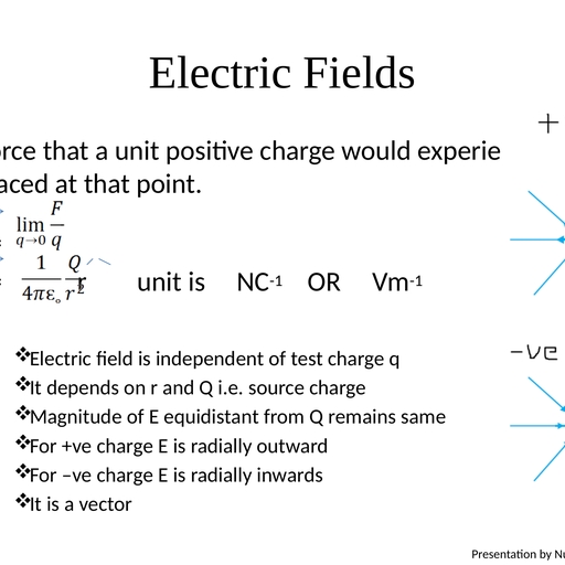
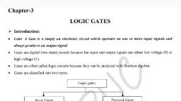
Logic Gates, • are thebasic building blocks of digital, electronics ,which process the digital signals in, a specific manner., • Logic gates are used in calculators, digital, watches, computers, robots, industrial control, systems, and in telecommunications., • In digital circuits only two values (represented, by 0 or 1) of the input and output voltage are, permissible.
Page 3 :
Logic gates, • A gate is a digital circuit that follows curtain logical, relationship between the input and output voltages., Therefore, they are generally known as logic gates — gates, because they control the flow of information., • The five common logic gates used are NOT, AND, OR, NAND,, NOR. Each logic gate is indicated by a symbol and its, function is defined by a truth table that shows all the, possible input logic level combinations with their respective, output logic levels., • Truth tables help understand the behaviour of logic gates., • These logic gates can be realised using semiconductor, devices.
Page 4 :
(i) NOT gate, • This is the most basic, gate, with one input and, one output. It produces a, ‘1’ output if the input is, ‘0’ and vice-versa. That is,, it produces an inverted, version of the input at its, output. This is why it is, also known as an inverter.
Page 5 :
OR Gate, • An OR gate has, two or more, inputs with one, output. The, output Y is 1 when, either input A or, input B or both are, 1s, that is, if any of, the input is high,, the output is high.
Page 6 :
(iii) AND Gate, • An AND gate, has two or, more inputs, and one, output. The, output Y of, AND gate is 1, only when, input A and, input B are, both 1.
Page 7 :
(iv) NAND Gate, • This is an AND gate, followed by a NOT gate., If inputs A and B are, both ‘1’, the output Y is, not ‘1’. The gate gets its, name from this NOT, AND behaviour., • NAND gates are also, called Universal Gates, since by using these, gates one can realise, other basic gates like, OR, AND and NOT
Page 8 :
(v) NOR Gate, • It has two or more, inputs and one, output. A NOToperation applied, after OR gate gives, a NOT-OR gate (or, simply NOR gate)., Its output Y is ‘1’, only when both, inputs A and B are, ‘0’, i.e., neither one, input nor the other, is ‘1’.
Page 9 :
identify the exact logic operation, carried out by these circuits.