Page 2 :
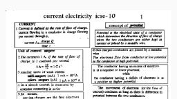
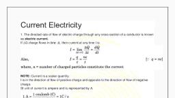
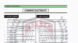
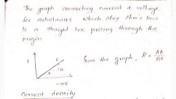
2, , Current Electricity, 1. Electric current (I), ►Electric current is the flow of charges., ►The intensity of electric current through any, point of a conductor is defined as the amount of, charge flowing per unit time., Q, total charge flowing, i.e, I=, =, t, timetaken, ►For steady current, rate of flow is constant and, does not vary with time., , 2. Current density (J), Current density is defined as the amount of, current flowing normally through unit area of a, conductor., , ►For a varying current, rate of flow is not uniform,, then intensity of electric current is the rate of flow of, charge., ΔQ dQ, =, i.e, I(t) = lim, dt, Δ t →0 Δ t, ►Electric current is a scalar quantity., ►SI unit is ampere (A). [ 1A = 1 C/s], ►Conventionally the direction of current is taken as, the direction of flow of positive charges (opposite to, flow of electrons)., I, A, ►current density is a vector quantity, ► SI unit is A/m2, i.e, J=, , Resistance(R), Ohm’s law states, that at constant temperature ►It is the opposition offered by the conductor to the, flow of current., and mechanical strain, the intensity of current, flowing through a conductor is directly proportional ►From Ohm’s law , R = V, I, to potential difference applied at its ends., ► SI unit of resistance is ohm(W)., i.e V a I, ► For V=1V and I=1A , R=1W., V = IR, where R is the constant of proportionality called, Thus the resistance of a conductor is said to be, resistance of the conductor., 1W if a current of 1A flows through the conductor, when a pd of 1V is applied between its ends., Conductance(C), It is the reciprocal of resistance., A, AB, 1, R=, ►Conductance, C =, C, B, BC, R, ►SI unit is mho or seimen(S) or W-1., , 3. Ohm’s Law, , 4. Ohmic conductors, Materials which obey ohm’s law are called ohmic, conductors., e.g:-Metals, Metallic alloys etc, , non-ohmic conductors, Materials which do not obey ohm’s law are called, non-ohmic conductors., e.g:-Electrolytes, gases, semi conductors, discharge, tube etc, , 5. Factors affecting resistance of a conductor, 1. Depends on nature of the material of the, conductor., 2. Directly proportional to length of the conductor., HSPTA KANNUR, , 3. Inversely proportional to area of cross section of, the conductor., 4. Directly proportional to temperature
Page 3 :
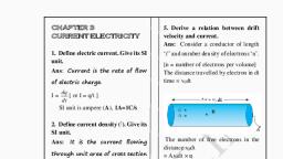
3, , Current Electricity, ►Resistivity is defined as the resistance per unit, length of a conductor having unit area of cross, At constant temperature, the resistance of a, section., conductor is directly proportional to length and, inversely proportional to area of cross section of the ►Unit of resistivity is ohm metre (Wm)., conductor., Factors affecting resistivity of a conductor, i.e, R a l, 1. Nature of the material of the conductor., R a 1/A, 2. Temperature., ρl, R=, Conductivity (σ ), A, It is the reciprocal of resistivity., where ρ is called resistivity /specific resistance of the, i.e, σ = 1/ρ ; unit is W-1m-1 or mho m-1., conductor., , 6. Resistivity/specific resistance(ρ), , Relation between Drift velocity and, In a metallic conductor there are a large number Relaxation time, Consider the flow of electron under an, of free electrons. In the absence of an electric field, electric, electric field E with drift velocity vd., they move randomly through the conductor with very, Then the force upon the electron,, high speed. But when a potential difference is, F = qE = eE, applied across a conductor, these free electrons get, But according to Newton’s second law,, drifted towards its positive end. During this flow, F = ma = eE., they will collide with the metallic atoms/positive, v, ions and their velocity decreases. The average, i.e,, m τd = eE. ( a = v/t ), velocity acquired by a free electron when it is drifted, eτE, eτ V, V, towards the positive end of a conductor under a, ×, then, vd =, =, (E =, ), m, m l, l, potential difference is called drift velocity., where ,V is the potential difference, between the ends of a conductor of length l., Relaxation time(t), eτ, Here,, = m ,the mobility of electrons., m, It is the average time interval between, V, successive collisions of electrons with the, There fore , vd = mE = m, l, atoms or positive ions in the conductor., or, μ = vd / E., ►Thus mobility is defined as the magnitude, of the drift velocity per unit electric field., ►Unit of mobility is CmN-1s-1 or Cs/kg ., , 7. Drift velocity(vd), , Problem :1. Current in a conductor is 10 mA. Calculate the number of electrons flowing in one hour., [Hint: q=? I =10mA =10 x 10−3 A, ,t = 1 hr=3600 s: ; q = It = 10 x 10−3 x 3600 =36 C ;, q, 36, =22.5 x 10¹⁹ ], q = ne ; n= =, −19, e 1.6 x 10, 2. A wire of resistance 4 W is stretched to twice its original length. The resistance of stretched wire, ρl ', ρ2 l, 4 ρl, would be ------ W [Hint- Resistance of the stretched wire is R'=, =, =, =16 W ], A', ( A/ 2), A, , HSPTA KANNUR
Page 4 :
4, , Current Electricity, 8. Relation between drift velocity and, electric current, Y l X, A, , I, , Consider a metallic conductor of area of cross, section A in which a current I is flowing. Let ‘n’ be, the number of electrons per unit volume, (number density). Now consider a cylindrical, volume XY in the conductor of length ‘l’., The number of electrons in this cylinder ,N = nAl, Total charge in the cylinder , q = Ne = nAle, q, nAle, then , current, I =, =, = neAvd, t, t, l, i.e , I = neAvd, (where vd =, ), t, , Relation between resistivity and relaxation time, We know that, I = neAvd, eτE, vd =, m, eτE, n e2 A τ E, I = neA×, =, m, m, V, but, E =, l, n e2 A τ V, then,, I=, ml, V, ml, =, = R (resistance of the conductor), I n e2 A τ, RA, ml, A, m, ×, resistivity, ρ=, =, =, 2, l, ne A τ l, n e2 τ, n e2 τ, conductivity, σ =, m, , V, Another form of ohm’s law (vector form), But, = E ,the electric field., ρl, l, We have ,V = IR, [here, R =, ], A, Hence,, E = ρ J or J = E/ρ. [ σ = 1/ρ ], ρl, V =I, = rl J, or ⃗, J =σ ⃗, E ., A, This is the vector form of ohm’s law., I, where J =, , current density., A, V, Then,, = ρJ, l, , 9. Limitations of Ohm’s law, 1. It is not a universal law., 4. The relation between V and I is not unique., 2. The relation between V and I depends on the i.e, there may be more than one value of V for the same, sign of V., value of current (A material exhibiting such a, 3. The relation between V and I is not linear, behaviour is GaAs)., , HSPTA KANNUR
Page 5 :
5, , Current Electricity, 10. Temperature dependence of resistance(or, resistivity), The resistance of metallic conductors is related to, temperature as, Rt = R0[1+a(T-T0)], or, ρt = ρ0[1+a(T-T0)], where Rt and R0 are the resistances at temperatures T oC, and T0oC(a reference temperature)., ’a’ is called temperature coefficient of resistance, having unit K-1 or oC-1. It is defined as the increase in, resistance per unit original resistance at 0oC per unit, rise of temperature., If R1 and R2 are resistances at temperatures T1oC and, T2oC respectively, then at T0 = 0oC,, R1 = R0(1+aT1), R2 = R0(1+aT2), Dividing the equations ,, R1, 1+ α T 1, =, R2, 1+ α T 2, on cross multiplying ,, , R1(1+aT2) = R2 (1+aT1), R1+R1aT2 = R2+R2aT1, a (R1T2 - R2T1 ) = R2 - R1, R 2−R1, a=, R 1 T 2−R2 T 1, ►The resistance of metals generally increases, with temperature. They are said to have positive, temperature coefficient of resistance., e.g:- Al, Cu, Brass etc, ►Resistance of certain materials do not change, with temperature. They have zero temperature, coefficient of resistance. Hence these materials, are used for making standard resistance wires in, resistance boxes., e.g:- manganin, constantan etc., ►Resistance of materials like semiconductors, decreases with rise in temperature. So these, materials have negative temperature coefficient, of resistance., e.g:- carbon, Germanium, Silicon etc., , Temperature–resistivity graph, Semiconductors, , Copper, , Nichrome, , 11. Colour code of carbon resistors, Carbon resistors has a set of concentric rings/bands of, different colours. The first two bands indicate the first two, digits of resistance. The third indicates decimal multiplier. The, last band stands for tolerance (percentage reliability)., , **Code:- B.B.Roy of Great Britain has a Very Good Wife., , HSPTA KANNUR, , ±, ±, ±
Page 7 :
7, , Current Electricity, 14. Internal resistance and terminal potential, difference of a cell, Internal resistance of a cell is defined as the, resistance offered by the cell when an electric current, flows through it. Internal resistance of a cell depends, on, (i) Nature of electrodes., (ii) Nature of electrolyte., (iii) Distance between electrodes., (iv) Area of the plates of electrodes., Terminal potential difference of a cell is the pd, between the terminals of the cell in closed circuit., This is always less than the emf of the cell by an, amount equal to the potential drop across the internal, resistance of the cell. This internal drop is known as, lost volt, The potential difference between +ve and -ve, electrode of a cell under open circuit case is called, emf (£-electromotive force)., , Consider a cell of emf E and internal resistance r, connected to an external resistor of resistance R. The, current I in the circuit is given by ,, E, I=, R+ r, E = IR + Ir, E, ×R, The terminal pd, V = IR =, R+ r, E, ×r, Lost volt inside the cell = Ir =, R+ r, also, E = V + Ir, .·. emf, E = terminal pd + lost volt, or,, terminal pd = emf – lost volt, , Note:- when I = 0 ; V = E ., Thus the terminal pd is equal to the emf of the cell when no current is drawn from it., , 15. Grouping of cells, (a) Cells in series, , Consider ‘m’ cells each of emf E, and internal resistance ‘r’, are connected in series. The, combination is connected to an, external resistor ‘R’. The current, in the circuit is given by, mE, I=, R+ mr, , (b) Cells in parallel, , (c) mixed grouping:-, , Consider ‘m’ cells each of emf E, and internal resistance ‘r’ are, connected in parallel. Effective, internal resistance r’ is given by,, 1/r' = 1/r + 1/r + 1/r +…… = m/r, , Each row has ‘n’ cells of emf ‘E’, and internal resistance ‘r’ and, there are ‘m’ such rows., Then the number of cells, N=mn, The effective emf in the circuit =, nE, Total resistance in the circuit =, nr/m + R, Then the current, I =, nE, mnE, =, mR+ nr, R+(nr /m), , then r' = r/m, Total effective resistance =R+r/m, Effective emf of the circuit = E, E, Main current, I =, (effective emf = mE ; effective, R+(r /m), resistance = R+mr ), mE, =, mR+ r, Problem :- A battery of emf 10 V and internal resistance 3 Ω is connected to a resistor. If the current in the, circuit is 0.5 A, what is the resistance of the resistor? What is the terminal voltage of the battery when the, circuit is closed?, [ Ans: 17 Ω , 8.5 V ], (NCERT 3.2), [ Hint- R = E/I – r , terminal pd, V = E – Ir ], HSPTA KANNUR
Page 8 :
8, , Current Electricity, 16. Electric power and energy, As a current flows through a wire, it increases, the vibrational kinetic energy of the atoms and hence, it generates heat. The energy dissipated per unit time, is called electric power., Consider the flow of electrons through a conductor, under a pd ‘V’ in time Δt, energy lost by a charge, Δq in moving from one point to another of a, conductor = V Δq., The energy dissipated per unit time, =V, , Δq, Δt, , = VI, , (where, , .·. Electric power , P = VI =I2R =, , Δq, Δt, V2, R, , =I), ., , ►SI unit of power is watt(W)., ►Another unit is horse power (hp)., 1Hp = 746 W, ►Electrical energy = Electric power x time =V I t, V2t, =, = I2 R t ., R, ►SI unit of electrical energy is joule (J)., ►Commercial unit is kilowatt hour (kWh), 1 kWh = 3.6 x 10⁶ J, ►Joule’s law of heating, It states that, the heat energy dissipated in a, current carrying conductor (resistor) is given by, H = I2 R t , where I is the current, R is the, resistance and t is the time of flow of current., , 17. Kirchhoff’s Rule, (i). First rule / junction rule / current rule., I2, The law states that algebraic, I1 O, sum of currents meeting at, I3, I5, a junction is zero., I4, Or, Current entering a junction = Current leaving the, junction., I1 + I 2 – I3 + I 4 – I5 = 0, or, I1 + I 2 + I4 = I 3 + I 5, ► This law is in accordance with law of, conservation of electric charge., (ii). Second law / loop rule / voltage rule., E, A, I1 1 D, , In loop AEFDA =>, I1R1 - I2R2 + E2 - E1 = 0, or,, I1R1 - I2R2 = E1 - E2, In loop EBCFE, In loop ABCDA, => I3R3 - E2 + I2R2 = 0, =>I3R3 - E1+ I1R1 = 0, or, I3R3 + I2R2 = E2, or, I1 R1 + I3R3 = E1, ► This law is in accordance with law of conservation, of energy, ►Sign convention- Following shows the method to, choose sign of emf and potential difference across, resistance (choose internal resistance as a resistance), , R1, R2 I2 E2 F, , E, I3, , R3, , B, C, The law states that the algebraic sum of the product, of the current and resistance in a closed circuit is, equal to the net emf in it., Problem :- Compute the number of electrons passing per second through an electric bulb of 60 W, 220 V, [Hint – P = 60 W ; V = 220 V ; P = IV ; I = P/V = 60/220 = 3/11 A, [ Ans : 1.02×10²⁰ ], 3×60, 180, Q = It =, =180/11 ; Q = ne ; n = Q/e =, = 1.02×10²⁰ ], −19, 11, 11×1.6×10, HSPTA KANNUR
Page 9 :
9, , Current Electricity, 18. Wheatstone’s principle, I1 = I g + I 3, I2 + I g = I 4, under balanced condition , Ig = 0 , then, P, Q, I1 = I3 ----------(1), Ig, I1, I2 = I4 ----------(2), C, A, G, Applying kirchhoff’s loop rule to loops ABDA &, BDCB, I2, I1P + IgG – I2R = 0, I4, R, S, IgG + I4S – I3Q = 0, under balanced condition , Ig = 0 , then, D, I1P – I2R = 0 or, I1P = I2R -----------(3), Key, I4S – I3Q = 0 or, I3Q = I4S -----------(4), Applying equations (1) & (2) in (3), Wheatstone’s bridge is an arrangement of four, I3P = I4S -----------(5), resistors as in fig. When no current flows through the Dividing equation (5)/(4) ;, P R, galvanometer, the bridge is said to be in balanced, =, condition ( ie, Ig = 0 )., Q S, Applying kirchhoff’s junction rule at junctions B and This is the balancing condition of a wheatstone’s, bridge. Knowing three resistors, the fourth resistor, D:, can be calculated., B, , I3, , 19. Metre bridge/slide wire bridge, , l1, , As the jockey slides over the wire AC, it shows zero, deflection at the balancing point (null point). If the, length AD is l1, then the length DC is ( 100−l1 )., Then, according to Wheatstone’s principle;, S, R, =, ;where ‘r’ is the, l 1 r (100−l1 )r, resistance per unit length of the metre bridge wire, Now, the unknown resistance can be calculated as,, Rl1, S=, (100−l 1), , The metre bridge, also known as the slide wire, bridge consists of a one metre long wire of uniform, ►The specific resistance or resistivity of the, cross sectional area, fixed on a wooden block. A, material of the wire can be then calculated by using, scale is attached to the block. Two gaps are formed, on it by using thick metal strips in order to make the, X Π a2, the relation, ρ=, Where ‘L’ is the length of, Wheat stones bridge., L, A resistance wire is introduced in gap S and the, the wire and ‘a’ its radius., resistance box is in gap R. One end of the, ►The balancing length remains unchanged, if the, galvanometer is connected to terminal B and its other, cell and galvanometer in Wheatstone bridge were, end is connected to a jockey D. A suitable resistance, interchanged., R is taken in the box and the circuit is closed., Problem :- The resistance of each arm of the Wheatstone’s bridge is 10 ohm. A resistance of 10 ohm is, connected in series with a galvanometer then the equivalent resistance across the battery will be---[Ans :10 ohm], [Hint- Under balanced condition, Ig = 0 (open circuit) ], HSPTA KANNUR
Page 10 :
10, , Current Electricity, 20. Potentiometer, Poentiometer is a device used to measure the Let ‘r’ be the resistance per unit length of the wire., potential difference accurately., When the key is closed, let I be the steady current, flowing through the circuit. Pd (fall of potential ) per, unit length of the wire = Ir, For a length l, the fall of potential = Irl, A, The positive of a cell E is connected to A and the, J, negative to a jockey through a galvanometer. This is, Rh, the secondary circuit. The jockey is moved along, B, the wire and the balancing length AJ = l, where the, galvanometer shows null deflection is found out., k, Then the, It consists of a uniform resistance wire AB of length, emf of the cell , E = pd between A and J = Irl, 10m. There are 2 circuits called primary and, i.e ,, Eαl, secondary. A metre scale is kept parallel to the, -----------------------------------------------------------segments help to measure the balancing length., Primary circuit consists of a cell (E), key and a ►Uses of potentiometer are :, rheostat and the secondary circuit consists of a cell 1. To compare the emf s of two cells, E1 , galvanometer, high resistance and a jokey as 2. To measure the internal resistance of a cell., shown in the figure. [ E> E 1], 21. Use 1 : To compare emf of two cells., The first cell E1 is included in the secondary circuit, by using the two-way key. The balancing length ‘l1’, is noted, then, E1 α l1 ------------(1), The second cell E2 is then included and the balancing, length l2 is noted ,then, E2 α l2 -----------(2), (1), (2), , =>, , E 1 l1, =, E 2 l2, , Connections are done as in the above diagram. The, primary circuit is closed., Problem :1. In a metre bridge, the balancing length from the left end (standard resistance of one ohm is in the right, gap) is found to be 20 cm. Find the value of the unknown resistance. [Ans. 0.25 ohm], Rl1, 1×20, =, = 0.25 ohm ], S=, (100−l 1), (100−20), 2. In a potentiometer arrangement, a cell of emf 1.25 V gives a balance point at 35.0 cm length of the wire., If the cell is replaced by another cell and the balance point shifts to 63.0 cm, what is the emf of the, second cell?, [ Ans : 2.25 V], (NCERT 3.12), E 1 l1, [Hint use, ], =, E 2 l2, , HSPTA KANNUR
Page 11 :
11, , Current Electricity, Use 2 : To find the internal resistance of a cell, ER, R+ r, cell., , ,where ‘r’ is the internal resistance of the, , Now if l2 is the balancing length then,, ER, α l ----------(2), R+ r 2, (1), (2), Connections are done as in the above diagram. A, resistance box R is connected across the cell through a, key K1. With the key open, determine the balancing, length l1. Then the emf of the cell,, E α l1 ----------(1), A suitable resistance R is taken in the resistance box, and the key K1 is closed. The pd at the terminals of the, cell falls to ‘terminal pd’, , =>, , R+ r l 1, =, R, l2, R+r =, , R l1, l2, , r=, , R l1, −R, l2, , r=, , R(l 1−l 2 ), l2, , ► Since potentiometer work on null deflection method, there is no current loss in potentiometer while, measuring emf. So potentiometer is preferred over voltmeter in measuring emf of a cell., , 22. Problems: 1. The drift velocity of free electron in a conductor is 7 x 10⁻⁶ ms−1. If the area of cross-section and, the number density of free electrons are 10−4 m 2 and 9 x 1028 m−3 respectively, calculate the current in it., [Hint: I = n e A ϑ d ; ϑ d=7 x 10⁻⁶ ms−1, n =9 x 1028 m−3, A=10−4 m 2, e= 1.6 x 10⁻¹⁹ C: I=10A ], 2. The number density of electrons in a copper conductor is 8.5 x 1028 m−3. How long does an electron take to, drift from one end of the wire of 3m long to its other end? The area of cross-section of the wire is 2 x 10⁻⁶, and it carries a current of 3A., [Hint: ϑ d =, , l, 3, 3, I, l, −4, =, ms−1; ϑ d= ; t= ϑ =, 28, −19, −6 =1.1x 10, n e A 8.5 x 10 x 1.6 x 10 x 2 x 10, t, 1.1 x 10⁻⁴, d, , =2.22x 10⁴ s], 3. A secondary cell has an e.m.f of 1.9 V and internal resistance of 380Ω. It is connected to an external, resistance of 20Ω. Calculate current from the cell., [Hint: V = IR = E – Ir ; I =, , E, 1.9, 1.9, =, =, = 0.00475 A], R +r 380+20 400, , 4. A silver wire has a resistance of 2.1Ω at 27.5°C and a resistance of 2.7Ω at 100°C. Determine its, temperature coefficient of resistance., [ Hint: ∝ =, , R2−R1, 2.7−2.1, 0.6, 0.6, =∝=, =, =, =0.0039. Ans: 3.9 x 10⁻³ /° C ], 2.1 x 100−2.7 x 27.5 210−74.25 135.75, R 1 t 2−R2 t 1, , HSPTA KANNUR
Page 12 :
12, , Current Electricity, 5. Resistance n, each of r ohm, when connected in parallel give an equivalent resistance of R ohm. If these, resistances were connected in series, what would be the effective resistance in ohms?, [When connected in parallel (1/R)=(n/r) or r=nR, then for series combination Reff=nr=n*nR = n2R], 6. A wire has a resistance of 12Ω. It is bent in the form of a circle. Find the effective resistance between, the two points on any diameter of the circle., [Ans: 3Ω], 7. A resistor of 5Ω resistance is connected in series with a parallel combination of a number of resistors, each of 6Ω. If the total resistance of the combination is 7Ω, how many resistors are in parallel? [Ans: 3], [hint- (n/6)=1/Rp or Rp=6/n. Then 7=5+(6/n) or 6/n=2 : n=3], , 23. Previous year questions, 1. a) Draw Wheatstone’s bridge and write its balancing condition.(2 mark), b) Determine the value of resistance R in the figure, assuming, that the current through the galvanometer (G) is zero. (2 mark), [ March 2021 ], 2. In the figure shown below, (a) Which are the resistors connected in parallel ?, (b) Calculate the current drawn from the cell, (3 mark), [ March 2021 ], 3. (a) Write the working principle of a potentiometer., (b) With a neat circuit diagram and with relevant equations explain how the emf of two cells are compared, using a potentiometer., (5 mark), [ March 2021 ], 4. Calculate the current flowing through the following circuit (2 mark)., [ Say 2021 ], 5. State the principle of a potentiometer. (2 mark), [ Say 2021 ], 6. A battery of emf 10 V and internal resistance 3 ohm is connected to an external resistor. If the current in, the circuit is 0.5 A, what is the value of the external resistance ? What is the terminal voltage of the battery, when the circuit is closed ? (2+1), [ Say 2021 ], 7. State Kirchhoff’s rules. (2), Use Kirchhoff’s rules to obtain conditions for the balance in Wheatstone bridge. (3) [ Say 2021 ], 8. Three resistors R1, R2, R3, are to be combined as, shown in the figures, a) Identify the series and parallel combinations., b) Which combination has lowest effective, resistance?, c) Arrive at the expression for the effective, resistance of parallel combination., [ March 2020 ], 9. A Wheatstone bridge is shown in figure., (a) Derive a relation connecting the four resistors for the galvanometer, to give zero or null deflection., (b) Name a practical device which uses this principle., [ March 2020 ], HSPTA KANNUR, , I1, A, I2, , P, R, , B I3, Ig, , Q, , G, I4 S, D, Key, , C
Page 13 :
13, , Current Electricity, 10. The figure shows the diagram of a potentiometer., (a) Give the principle of a potentiometer., (b) The length of AB is 3 m and resistance per unit length of the, potentiometer wire is 4 ohm/m. If E1 = 4V, R = 20 ohm and E2 = 1 V, find the length of the potentiometer wire that balances E2 ., (c) If E2 > E1 can we get the null deflection in galvanometer. Give reason, [ Say 2020 ], 11. You are given three resistors each of resistance R., (a) How will you combine them to get the, (i) Maximum effective resistance, (ii) Minimum effective resistance, (b) Derive equation for minimum effective resistance., [ Say 2020 ], 12. The temperature dependence of resistivity of a material is shown below, (a) Identify the type of material. (1), (b) Write the relation between resistivity and average collision time for electron. (1), [ March 2019 ], 13. The experimental set up to find an unknown resistance using a Metre bridge is shown below:, (a) What is the working principle of Metre bridge? (1 mark), (b) If the balance point is found to be at 39.5 cm from the end A, the, resister S is of 12.5 ohm. Determine the resistance R. Why are the, connection between resistors in a metre bridge made of thick copper, strips? (score:2+1), (c) If the galvanometer and the cell are interchanged at the balance point, of the bridge would the galvanometer show any current? (1 mark), [ March 2019 ], 14. (a) with suitable circuit diagram, show how emfs of two cells can be compared using potentiometer, (b) why do we prefer potentiometer to measure the e.m.f. of a cell than a voltmeter? [ Say 2019 ], 15. (a) Express ohm's law in terms of current density and conductivity. (1), (b) Draw a graph showing the variation of resistivity with temperature, for a semiconductor. (1 mark), (c) Find the equivalent resistance of the network between the points, P and Q. (3 mark), [ Say 2019 ], 16. How will you represent a resistance of 3700 Ω ± 5% using colour code? (1 mark) [ March 2018 ], 17. What do you mean by drift velocity ? Write the relation between drift velocity and electric current., (2 mark), [ March 2018 ], 18. The circuit diagram of a potentiometer for determining the emf 'E' of, a cell of negligible internal resistance is as shown in figure., (a) State the principle of working of a potentiometer., (b) How the balancing length AI changes when the, value of Rl decreases., (c) Derive an expression to find out internal resistance of a cell., (Score: 1+1+3), [ March 2018 ], 19. A uniform wire of resistance 40ohm is cut into 4 equal part and they are connected parallel. Find effective, resistance of the combination? (2), [ Say 2018 ], , HSPTA KANNUR
Page 14 :
14, , Current Electricity, 20. The experimental setup for the comparison two resistances is shown below, (a) The working principle of the above device is ………, (b) In figure, Let R is the effective resistance of series combination of, two 3 Ω resistors and S is the effective resistance of parallel, combination of two 3 Ω resistors. The balancing point is obtained at, D. If the length AC is 100, find the length AD of the wire., (score :1+2), [ Say 2018 ], 21. The circuit shown can be analyzed using Kirchhoff’s law, (a) Apply Kirchhoff s first law to the point B., (b) State Kirchhoff’s second law., (c) Apply Kirchhoff s second law to the mesh ABFGA., (score :1+2+1), [ Say 2018 ], , 24. Additional Problems1. The resistance of a wire is ‘R’ ohm. If it is melted and stretched, to ‘n’ times its original length, its new, resistance will be, (NEET 2017), R, R, 2, (a), (b) n R, (c) 2, (d) nR, n, n, 2. The electric resistance of a certain wire of iron is R. If its length and radius are both doubled, then, (a) The resistance will be doubled and the specific resistance will be halved, (b) The resistance will be halved and the specific resistance will remain unchanged, (c) The resistance will be halved and the specific resistance will be doubled, (d) The resistance and the specific resistance, will both remain unchanged, (2004), –4, –1, –10, –1, 3. A charged particle having drift velocity of 7.5 ×10 m s in an electric field of 3 ×10 Vm , has a, mobility in m2V–1s–1 of, (NEET 2020), 15, 6, -6, –15, (a) 2.25×10, (b) 2.5 ×10, (c) 2.5 ×10, (d) 2.25 ×10, 4. The color code of a resistance is given below, , The values of resistance and tolerance, respectively, are, (NEET 2020), (a) 470 kΩ , 5% (b) 47 kΩ , 10%, (c) 4.7 kΩ , 5%, (d)470 Ω, 5%, 5. The solids which have the negative temperature coefficient of resistance are, (a) metals, (b) insulators only, (c) semiconductors only, (d) insulators and semiconductors. (NEET 2020), 6. Copper and silicon is cooled from 300 K to 60 K, the specific resistance, (a) decreases in copper but increases in silicon (b) increases in copper but decreases in silicon, (c) increases in both, (d) decreases in both., (2001), 2, 7. The charge flowing through a resistance R varies with time t as Q = at – bt , where a and b are positive, constants. The total heat produced in R is, (NEET 2016), 3, 3, 3, 3, a R, a R, a R, a R, (a), (b), (c), (d), 2b, b, 6b, 3b, 8. A 5 ampere fuse wire can withstand a maximum power of 1 watt in the circuit. The resistance of the, fuse wire is, (2005), (a) 0.04 ohm, (b) 0.2 ohm, (c) 5 ohm, (d) 0.4 ohm, HSPTA KANNUR
Page 15 :
15, , Current Electricity, 9. Two bulbs are of (40 W, 200 V), and (100 W, 200 V). Then correct relation for their resistances is, (a) R40 < R100, (b) R40 > R 100, (2000), (c) R40 = R100, (d) no relation can be predicted., 10. A wire of resistance 12 ohms per meter is bent to form a complete circle of radius 10 cm. The, resistance between its two diametrically opposite points, A and B as shown in the figure is, (a) 3 Ω, (b) 6π Ω, (c) 6 Ω, (d) 0.6π Ω, (2009), 11. In a potentiometer two cells are connected in series first to support one another and then in opposite, direction. The balancing points are obtained at 50 cm and 10 cm from the positive end of the wire in the, two cases. The ratio of emf’s is:, NEET-2016, A)3:2, B) 5:1, C)5:4, D)3:4, 12. The amount of charge flowing per unit area normal to the flow is called (KEAM ENGG-2016), A) Electrical conductivity, B)Electrical resistivity, C) Mobility, D) Current density E) Areal current, 13. Nichrome is used as the electrical heating element because of its, (KEAM ENGG-2016), A) Negative temperature coefficient of resistance, B) Low melting point, C) Weak dependence of resistivity with temperature, D) Semiconducting nature, E) Strong dependence of resistivity with temperature, 14. Consider the following two statements., (2010), (A) Kirchhoff ’s junction law follows from the conservation of charge., (B) Kirchhoff ’s loop law follows from the conservation of energy. Which of the following is correct?, (a) Both (A) and (B) are wrong., (b) (A) is correct and (B) is wrong., (c) (A) is wrong and (B) is correct., (d) Both (A) and (B) are correct., 15. n equal resistors are first connected in series and then connected in parallel. What is the ratio of the, maximum to the minimum resistance ?, (a) n, (b) 1/n2, (c) n2, (d) 1/n, Answer - Additional problems, ρl ', ρ nl, n2 ρ l, 1. Ans. b Resistance of the stretched wire is R’=, =, =, = n2R; Here used A'l'=Al, A, ( A/n), A', 2. Ans. b, 3. Ans. b, Mobility μ = Vd/E = e τ/m, 4. Ans d, 5. Ans. D, 6. (a) : Specific resistance is a property of a material and it increases with the increase of, temperature, but not vary with the dimensions (length, cross-section) of the conductor, 7. Ans. C (I =dQ/dt= a − 2 bt & At t=0, Q =0 ⇒ I =0 Also, I=0 at t = a/2b & Heat produced is, 8. Ans. a : P = i 2 R or 1 = 25 × R, 9. Ans. b : P =V2/R or, R ∝(1/P ), 10.Ans. d : Wire of length 2π× 0.1 m of resistance 12 Ω/m is bent to form a circle., Resistance of each part= 12 × π × 0.1 = 1.2π Ω, 11. Ans. a (Hint- E1+E2 α 50 & E1-E2 α 10), 12. Ans d, 13. Ans: C Weak dependence of resistivity with temperature, 14. Ans d, 15. Ans. C, , HSPTA KANNUR