Page 1 :
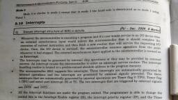
Unit- I, Interrupts Programming in 8051, [Interrupts vs polling, Sources of interrupts, vector table, enabling and disabling, TCON and IE registers,, interrupt priority, IP register, programming external interrupts (Level and edge triggering ), programming, serial communication interrupts (Mode1) and timer interrupts (mode1) (Use ALP and C during, programming)], , Introduction, Interrupt is one of the most important and powerful concepts and features, in microcontroller/processor applications. Almost all the real world and real time systems, built around microcontrollers and microprocessors make use of interrupts., The interrupts refer to a notification, communicated to the controller, by a, hardware device or software, on receipt of which controller momentarily stops and responds, to the interrupt. Whenever an interrupt occurs the controller completes the execution of the, current instruction and starts the execution of an Interrupt Service Routine (ISR) or, Interrupt Handler. ISR is a piece of code that tells the processor or controller what to do, when the interrupt occurs. After the execution of ISR, controller returns back to the, instruction it has jumped from (before the interrupt was received). The interrupts can be, either hardware interrupts or software interrupts., , Interrupts vs polling, An application built around microcontrollers generally has the following structure. It takes, input from devices like keypad, ADC etc; processes the input using certain algorithm; and, generates an output which is either displayed using devices like seven segment, LCD or used, further to operate other devices like motors etc. In such designs, controllers interact with the, inbuilt devices like timers and other interfaced peripherals like sensors, serial port etc. The, programmer needs to monitor their status regularly like whether the sensor is giving output,, whether a signal has been received or transmitted, whether timer has finished counting, or if, an interfaced device needs service from the controller, and so on. This state of continuous, monitoring is known as polling., In polling, the microcontroller keeps checking the status of other devices; and while, doing so it does no other operation and consumes all its processing time for monitoring. This, problem can be addressed by using interrupts. In interrupt method, the controller responds to, only when an interruption occurs. Thus in interrupt method, controller is not required to, regularly monitor the status (flags, signals etc.) of interfaced and inbuilt devices., To understand the difference better, consider the following. The polling method is, very much similar to a salesperson. The salesman goes door-to-door requesting to buy its, product or service. Like controller keeps monitoring the flags or signals one by one for all, devices and caters to whichever needs its service. Interrupt, on the other hand, is very similar, to a shopkeeper. Whosoever needs a service or product goes to him and apprises him of, his/her needs. In our case, when the flags or signals are received, they notify the controller, that they need its service.
Page 2 :
Comparison Chart, BASIS FOR, COMPARISON, , INTERRUPT, , POLLING, , Basic, , Device notify CPU that it needs, CPU attention., , CPU constantly checks device, status whether it needs CPU's, attention., , Mechanism, , An interrupt is a hardware, mechanism., , Polling is a Protocol., , Servicing, , Interrupt handler services the, Device., , CPU services the device., , Indication, , Interrupt-request line indicates that, device needs servicing., , Comand-ready bit indicates the, device needs servicing., , CPU, , CPU is disturbed only when a, device needs servicing, which saves, CPU cycles., , CPU has to wait and check, whether a device needs servicing, which wastes lots of CPU cycles., , Occurrence, , An interrupt can occur at any time., , CPU polls the devices at regular, interval., , Efficiency, , Interrupt becomes inefficient when, devices keep on interrupting the, CPU repeatedly., , Polling becomes inefficient when, CPU rarely finds a device ready, for service., , Example, , Let the bell ring then open the door, to check who has come., , Constantly keep on opening the, door to check whether anybody, has come., , Hardware and Software interrupt, The interrupts in a controller can be either hardware or software. If the interrupts are, generated by the controller’s inbuilt devices, like timer interrupts; or by the interfaced, devices, they are called the hardware interrupts. If the interrupts are generated by a piece of, code, they are termed as software interrupts., Multiple interrupts, What would happen if multiple interrupts are received by a microcontroller at the same, instant? In such a case, the controller assigns priorities to the interrupts. Thus the interrupt, with the highest priority is served first. However the priority of interrupts can be changed, configuring the appropriate registers in the code., Sources of interrupts, The 8051 controller has six hardware interrupts of which five are available to the, programmer. These are as follows:
Page 3 :
Fig. 1: Image showing 8051 Interupts, 1. RESET interrupt – This is also known as Power on Reset (POR). When the RESET, interrupt is received, the controller restarts executing code from 0000H location. This is an, interrupt which is not available to or, better to say, need not be available to the programmer., 2. Timer interrupts – Each Timer is associated with a Timer interrupt. A timer interrupt, notifies the microcontroller that the corresponding Timer has finished counting., 3. External interrupts – There are two external interrupts EX0 and EX1 to serve external, devices. Both these interrupts are active low. In AT89C51, P3.2 (INT0) and P3.3 (INT1), pins are available for external interrupts 0 and 1 respectively. An external interrupt notifies, the microcontroller that an external device needs its service., 4. Serial interrupt – This interrupt is used for serial communication. When enabled, it, notifies the controller whether a byte has been received or transmitted., Types of interrupt in 8051 Microcontroller, Let's see the five sources of interrupts in 8051 Microcontroller:, o, o, o, o, o, , Timer 0 overflow interrupt - TF0, External hardware interrupt - INT0, Timer 1 overflow interrupt - TF1, External hardware interrupt - INT1, Serial communication interrupt - RI/TI, , The timer and serial interrupts are internally produced by the microcontroller, whereas the, external interrupts are produced by additional interfacing devices or switches that are, externally connected with the microcontroller. These external interrupts can be level, triggered or edge triggered., , Interrupt Vector Table, Every interrupt is assigned a fixed memory area inside the processor/controller. The Interrupt, Vector Table (IVT) holds the starting address of the memory area assigned to it, (corresponding to every interrupt)., The interrupt vector table (IVT) for AT89C51 interrupts is as follows :, , Interrupt, , ROM Location (Hex), , Pin, , Flag clearing
Page 4 :
Reset, 0000, 9, Auto, External interrupt 0, 0003, 12, Auto, Timer interrupt 0, 000B, –, Auto, External interrupt 1, 0013, 13, Auto, Timer interrupt 1, 001B, –, Auto, Serial COM interrupt, 0023, –, Programmer clears it, When an interrupt is received, the controller stops after executing the current, instruction. It transfers the content of program counter into stack. It also stores the current, status of the interrupts internally but not on stack. After this, it jumps to the memory location, specified by Interrupt Vector Table (IVT). After that the code written on that memory area, gets executed. This code is known as the Interrupt Service Routine (ISR) or interrupt, handler. ISR is a code written by the programmer to handle or service the interrupt., , Enabling and disabling, Upon Reset, all the interrupts are disabled even if they are activated. The interrupts must be, enabled using software in order for the microcontroller to respond to those interrupts., IE (interrupt enable) register is responsible for enabling and disabling the interrupt. IE is a, bit addressable register., Interrupt Structure of 8051 Microcontroller, After 'RESET' all the interrupts get disabled, and therefore, all the interrupts is enabled by, software. From all the five interrupts, if anyone or all interrupt are activated, this will sets the, corresponding interrupt flags as represent in the figure which corresponds to Interrupt, structure of 8051 microcontroller:-
Page 5 :
All the interrupts can be set or cleared by some special function register that is also known as, interrupt enabled (IE), and it is totally depends on the priority, which is executed by using, interrupt priority register., , Interrupt Enable (IE) Register, IE register is used for enabling and disabling the interrupt. This is a bit addressable register, in which EA value must be set to one for enabling interrupts. The individual bits in this, register enables the particular interrupt like timer, serial and external inputs. Consider in the, below IE register, bit corresponds to 1 activate the interrupt and 0 disable the interrupt., , TCON Register:, Timer Control or TCON Register is used to start or stop the Timers of 8051 Microcontroller., It also contains bits to indicate if the Timers has overflowed. The TCON SFR also consists, of Interrupt related bits., , The following table gives the description of each bit in the TCON SFR.
Page 6 :
TF1 TCON.7 Timer 1 overflow flag. Set by hardware when timer/counter 1, overflows. Cleared by hardware as the processor vectors to the interrupt service routine., TR1 TCON.6 Timer 1 run control bit. Set/cleared by software to turn, timer/counter 1 on/off., TF0 TCON.5 Timer 0 overflow flag. Set by hardware when timer/counter 0, overflows. Cleared by hardware as the processor vectors to the service routine., TR0 TCON.4 Timer 0 run control bit. Set/cleared by software to turn, timer/counter 0 on/off., IE1 TCON.3 External interrupt 1 edge flag. Set by CPU when the, external interrupt edge (H-to-L transition) is detected. Cleared by CPU when the interrupt is, processed. Note: This flag does not latch low-level triggered interrupts., IT1 TCON.2 Interrupt 1 type control bit. Set/cleared by software to, specify falling edge/low-level triggered external interrupt., IE0 TCON.1 External interrupt 0 edge flag. Set by CPU when external, interrupt (H-to-L transition) edge is detected. Cleared by CPU when interrupt is, processed. Note: This flag does not latch low-level triggered interrupts., IT0 TCON.0 Interrupt 0 type control bit. Set/cleared by software to specify, falling edge/low-level triggered external interrupt., Figure 11-6. TCON (Timer/Counter) Register (Bit-addressable), ITO and IT1, TCON.O and TCQN.2 are referred to as ITO and IT 1, respectively. These two bits set the, low-level or edge-triggered modes of the external hardware interrupts of the INTO and INT1, pins. They are both 0 upon reset, which makes them low-level triggered. The programmer, can make either of them high to make the external hardware interrupt edge-triggered. In a, given system based on the 8051, once they are set to 0 or 1 they will not be altered again, since the designer has fixed the interrupt as either edge- or level-triggered., IE0 and IE1, TCON.L and TCON.3 are referred to as IEO and IE1, respectively. These bits are used by, the 8051 to keep track of the edge-triggered interrupt only. In other words, if the ITO and, IT1 are 0, meaning that the hardware interrupts are low-level triggered, IEO and IE1 are not, used at all. The IEO and IE1 bits are used by the 8051 only to latch the high-to-low edge, transition on the INTO and INT1 pins. Upon the edge transition pulse on the INT0 (or INT1), pin, the 8051 marks (sets high) the IE* bit in the TCON register, jumps to the vector in the, interrupt vector table, and starts to execute the ISR. While it is executing the ISR, no H-to-L, pulse transition on the INTO (or INT1) is recognized, thereby preventing any interrupt inside, the interrupt. Only the execution of the RETI instruction at the end of the ISR will clear the, lEx bit, indicating that a new H-to-L pulse will activate the interrupt again. From this, discussion we can see that the IEO and IE1 bits are used internally by the 8051 to indicate
Page 7 :
whether or not an interrupt is in use. In other words, the programmer is not concerned with, these bits since they are solely for internal use., TRO and TR1, These are the D4 (TCON.4) and D6 (TCON.6) bits of the TCON register. We were, introduced to these bits in Chapter 9. They are used to start or stop timers 0 and 1,, respectively. Although we have used syntax such as “SETB TRx” and “CLR Trx”, we could, have used instructions such as “SETB TCON.4″ and “CLR TCON. 4″ since TCON is a bitaddressable register. TFO and TF1, These are the D5 (TCON.5) and D7 (TCON.7) bits of the TCON register. We were, introduced to these bits in Chapter 9. They are used by timers 0 and 1, respectively, to, indicate if the timer has rolled over. Although we have used the syntax “JNB TFx, target”, and “CLR Trx”, we could have used instructions such as “JNB TCON. 5, target” and “CLR, TCON. 5″ since TCON is bit-addressable., , Interrupt priority, Interrupt priority upon reset, When the 8051 is powered up, the priorities are assigned according to Table . From Table, we see, for example, that if external hardware interrupts 0 and 1 are activated at the same, time, external interrupt 0 (INTO) is responded to first. Only after INTO has been serviced is, INT1 serviced, since INT1 has the lower priority. In reality, the priority scheme in the table, is nothing but an internal polling sequence in which the 8051 polls the interrupts in the, sequence listed in Table , and responds accordingly., Interrupt Source, , Vector address, , Interrupt priority, , External Interrupt 0 –INT0, , 0003H, , 1, , Timer 0 Interrupt, , 000BH, , 2, , External Interrupt 1 –INT1, , 0013H, , 3, , Timer 1 Interrupt, , 001BH, , 4, , Serial Interrupt, , 0023H, , 5, , Interrupt Priority Register (IP), We can alter the interrupt priority by assigning the higher priority to any one of the, interrupts. This is accomplished by programming a register called IP (interrupt priority)., Using IP register it is possible to change the priority levels of an interrupts by clearing or, setting the individual bit in the Interrupt priority (IP) register as shown in figure. It allows the, low priority interrupt can interrupt the high-priority interrupt, but it prohibits the interruption, by using another low-priority interrupt. If the priorities of interrupt are not programmed, then
Page 8 :
microcontroller executes the instruction in a predefined manner and its order are INT0, TF0,, INT1, TF1, and SI., The following figure shows the bits of IP register. Upon reset, the IP register contains all, 0's. To give a higher priority to any of the interrupts, we make the corresponding bit in the, IP register high., -, , -, , -, , -, , PT1, , PX1, , PT0, , -, , IP.7, , Not Implemented., , -, , IP.6, , Not Implemented., , -, , IP.5, , Not Implemented., , -, , IP.4, , Not Implemented., , PT1, , IP.3, , Defines the Timer 1 interrupt priority level., , PX1, , IP.2, , Defines the External Interrupt 1 priority level., , PT0, , IP.1, , Defines the Timer 0 interrupt priority level., , PX0, , IP.0, , Defines the External Interrupt 0 priority level., , PX0, , Programming external interrupts (Level and edge triggering ), The 8051 has two external hardware interrupts. Pin 12 (P3.2) and pin 13 (P3.3) of the 8051,, designated as INTO and INT1, are used as external hardware interrupts. Upon activation of, these pins, the 8051 gets interrupted in whatever it is doing and jumps to the vector table to, perform the interrupt service routine. In this section we study these two external hardware, interrupts of the 8051 with some examples., , Figure 11-4. Activation of INTO and INT1, , External interrupts INTO and INT1, There are only two external hardware interrupts in the 8051: INTO and INT1. They are, located on pins P3.2 and P3.3 of port 3, respectively. The interrupt vector table locations, 0003H and 0013H are set aside for INTO and INT1, respectively. They are enabled and, disabled using the IE register. There are two types of activation for the external hardware
Page 9 :
interrupts: (1) level triggered, and (2) edge triggered. Let’s look at each one. First, we see, how the level-triggered interrupt works., Level-triggered interrupt, In the level-triggered mode, INTO and INT1 pins are normally high (just like all I/O port, pins) and if a low-level signal is applied to them, it triggers the interrupt. Then the, microcontroller stops whatever it is doing and jumps to the interrupt vector table to service, that interrupt. This is called a level-triggered or level-activated interrupt and is the default, mode upon reset of the 8051. The low-level signal at the INT pin must be removed before, the execution of the last instruction of the interrupt service routine, RETI; otherwise, another, interrupt will be generated. In other words, if the low-level interrupt signal is not removed, before the ISR is finished it is interpreted as another interrupt and the 8051 jumps to the, vector table to execute the ISR again. Look at Example 11-5., Example 11-5, Assume that the INT1 pin is connected to a switch that is normally high. Whenever it goes, low, it should turn on an LED. The LED is connected to PI .3 and is normally off. When it is, turned on it should stay on for a fraction of a second. As long as the switch is pressed low,, the LED should stay on., Solution:, , In this program, the microcontroller,is looping continuously in the HERE loop. Whenever, the switch on INT1 (pin P3.3) is activated, the microcontroller gets out of the loop and jumps, to vector location 0013H. The ISR for INT1 turns on the LED, keeps it on for a while, and
Page 10 :
turns it off before it returns. If by the time it executes the RETI instruction, the INT1 pin is, still low, the microcontroller initiates the interrupt again. Therefore, to end this problem, the, INT1 pin must be brought back to high by the time RETI is executed., , Sampling the low level-triggered interrupt, Pins P3.2 and P3.3 are used for normal I/O unless the INTO and INT1 bits in the IE registers, are enabled. After the hardware interrupts in the IE register are enabled, the controller keeps, sampling the INT« pin for a low-level signal once each machine cycle. According to one, manufacturer’s data sheet “the pin must be held in a low state until the start of the execution, of ISR. If the INTn pin is brought back to a logic high before the start of the execution of, ISR there will be no interrupt.” However, upon activation of the interrupt due to the low, level, it must be brought back to high before the execution of RETI. Again, according to one, manufacturer’s data sheet, “If the INTw pin is left at a logic low after the RETI instruction of, the ISR, another interrupt will be activated after one instruction is executed.” Therefore, to, ensure the activation of the hardware interrupt at the INTw pin, make sure that the duration, of the low-level signal is around 4 machine cycles, but no more. This is due to the fact that, the level-triggered interrupt is not latched. Thus the pin must be held in a low state until the, start of the ISR execution., , Figure 11-5. Minimum Duration of the Low Level-Triggered Interrupt (XTAL = 11.0592, MHz), , Edge-triggered interrupts, As stated before, upon reset the 8051 makes INTO and INT1 low-level triggered interrupts., To make them edge-triggered interrupts, we must program the bits of the TCON register., The TCON register holds, among other bits, the ITO and IT1 flag bits that determine levelor edge-triggered mode of the hardware interrupts. ITO and IT1 are bits DO and D2 of the, TCON register, respectively. They are also referred to as TCON.O and TCON.2 since the, TCON register is bit-addressable. Upon reset, TCON.O (ITO) and TCON.2 (III) are both Os,, meaning that the external hardware interrupts of INTO and INT1 pins are low-level, triggered. By making the TCON.O and TCON.2 bits high with instructions such as “SETB, TCON. 0″ and “SETB TCON. 2″, the external hardware interrupts of INTO and INT1, become edge-triggered. For example, the instruction “SETB CON. 2″ makes INT1 what is, called an edge-triggered interrupt, in which, when a high-to-low signal is applied to pin, P3.3, in this case, the controller will be interrupted and forced to jump to location 0013H in, the vector table to service the ISR (assuming that the interrupt bit is enabled in the IE, register)., Look at Example 11-6. Notice that the only difference between this program and the, program in Example 11-5 is in the first line of MAIN where the instruction “SETB TCON.
Page 11 :
2″ makes INT1 an edge-triggered interrupt. When the falling edge of the signal is applied to, pin INT1, the LED will be turned on momentarily. The LED’s on-state duration depends on, the time delay inside the ISR for nSTTl. To turn on the LED again, another high-to-low, pulse must be applied to pin 3.3. This is the opposite of Example 11-5. In Example 11-5, due, to the level-triggered nature of the interrupt, as long as INT1 is kept at a low level, the LED, is kept in the on state. But in this example, to turn on the LED again, the INT1 pulse must be, brought back high and then forced low to create a falling edge to activate the interrupt., Example 11-6, Assuming that pin 3.3 (INT1) is connected to a pulse generator, write a program in which the, falling edge of the pulse will send a high to PI.3, which is connected to an LED (or buzzer)., In other words, the LED is turned on and off at the same rate as the pulses are applied to the, INT1 pin. This is an edge-triggered version of Example 11-5., , Sampling the edge-triggered interrupt, Before ending this section, we need to answer the question of how often the edge-triggered, interrupt is sampled. In edge-triggered interrupts, the external source must be held high for at, least one machine cycle, and then held low for at least one machine cycle to ensure that the, transition is seen by the microcontroller., , The falling edge is latched by the 8051 and is held by the TCON register. The TCON. 1 and, TCON.3 bits hold the latched falling edge of pins INTO and INT1, respectively. TCON.l and, TCON.3 are also called IEO and IE1, respectively, as shown in Figure 11-6. They function, as interrupt-in-service flags. When an interrupt-in-service flag is raised, it indicates to the, external world that the interrupt is being serviced and no new interrupt on this INTw pin will, be responded to until this service is finished. This is just like the busy signal you get if
Page 12 :
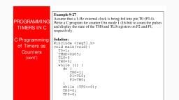
calling a telephone number that is in use. Regarding the ITO and IT1 bits in the TCON, register, the following two points must be emphasized., 1. The first point is that when the ISRs are finished (that is, upon execution of, instruction RETI), these bits (TCON.l and TCON.3) are cleared, indicating, that the interrupt is finished and the 8051 is ready to respond to another inter, rupt on that pin. For another interrupt to be recognized, the pin must go back, to a logic high state and be brought back low to be considered an edge-trig, gered interrupt., 2. The second point is that while the interrupt service routine is being executed,, the INT« pin is ignored, no matter how many times it makes a high-to-low, transition. In reality one of the functions of the RETI instruction is to clear the, corresponding bit in the TCON register (TCON. 1 or TCON.3). This informs us, that the service routine is no longer in progress and has finished being serv, iced. For this reason, TCON. 1 and TCON.3 in the TCON register are called, interrupt-in-service flags. The interrupt-in-service flag goes high whenever a, falling edge is detected at the INT pin, and stays high during the entire execu, tion of the ISR. It is only cleared by RETI, the last instruction of the ISR., Because of this, there is no need for an instruction such as “CLR TCON. 1″, (or “CLR TCON. 3″ for INT1) before the RETI in the ISR associated with the, hardware interrupt INTO. As we will see in the next section, this is not the case, for the serial interrupt., Example 11-7, What is the difference between the RET and RETI instructions? Explain why we cannot use, RET instead of RETI as the last instruction of an ISR., Solution:, Both perform the same actions of popping off the top two bytes of the stack into the program, counter, and making the 8051 return to where it left off. However, RETI also performs an, additional task of clearing the interrupt-in-service flag, indicating that the servicing of the, interrupt is over and the 8051 now can accept a new interrupt on that pin. If you use RET, instead of RETI as the last instruction of the interrupt service routine, you simply block any, new interrupt on that pin after the first interrupt, since the pin status would indicate that the, interrupt is still being serviced. In the cases of TFO, TF1, TCON.l, and TCON.3, they are, cleared by the execution of RETI., Programming serial communication interrupts (Mode1) and timer interrupts (mode1), 1. Programming Timer Interrupts, The timer interrupts IT0 and IT1 are related to Timers 0 and 1, respectively. (Please, refer 8051 Timers for details on Timer registers and modes.) The interrupt programming for, timers involves following steps :, 1. Configure TMOD register to select timer(s) and its/their mode., 2. Load initial values in THx and TLx for mode 0 and 1; or in THx only for mode 2.
Page 13 :
3. Enable Timer Interrupt by configuring bits of IE register., 4. Start timer by setting timer run bit TRx., 5. Write subroutine for Timer Interrupt. The interrupt number is 1 for Timer0 and 3 for, Timer1. Note that it is not required to clear timer flag TFx., 6. To stop the timer, clear TRx in the end of subroutine. Otherwise it will restart from 0000H, in case of modes 0 or 1 and from initial values in case of mode 2., 7. If the Timer has to run again and again, it is required to reload initial values within the, routine itself (in case of mode 0 and 1). Otherwise after one cycle timer will start counting, from 0000H., Example code, Timer interrupt to blink an LED; Time delay in mode1 using interrupt method, // Use of Timer mode0 for blinking LED using interrupt method, // XTAL frequency 11.0592MHz, #include<reg51.h>, sbit LED = P1^0;, //LED connected to D0 of port 1, void timer(void) interrupt 1, {, led=~led;, TH0=0xFC;, TL0=0x66;, }, main(), {, TMOD = 0x01;, TH0 = 0xFC;, TL0 = 0x66;, IE = 0x82;, TR0 = 1;, while(1);, }, , //interrupt no. 1 for Timer 0, //toggle LED on interrupt, // initial values loaded to timer, , // mode1 of Timer0, // initial values loaded to timer, // enable interrupt, //start timer, // do nothing, , 2. Programming External Interrupts, The external interrupts are the interrupts received from the (external) devices interfaced with, the microcontroller. They are received at INTx pins of the controller. These can be level, triggered or edge triggered. In level triggered, interrupt is enabled for a low at INTx pin;, while in case of edge triggering, interrupt is enabled for a high to low transition at INTx pin., The edge or level trigger is decided by the TCON register. The TCON register has following, bits:
Page 14 :
Fig. 3: Bit Values of TCON Register of 8051 Microcontroller, Setting the IT0 and IT1 bits make the external interrupt 0 and 1 edge triggered respectively., By default these bits are cleared and so external interrupt is level triggered., Note : For a level trigger interrupt, the INTx pin must remain low until the start of the ISR, and should return to high before the end of ISR. If the low at INTx pin goes high before the, start of ISR, interrupt will not be generated. Also if the INTx pin remains low even after the, end of ISR, the interrupt will be generated once again. This is the reason why level trigger, interrupt (low) at INTx pin must be four machine cycles long and not greater than or smaller, than this., Following are the steps for using external interrupt :, 1. Enable external interrupt by configuring IE register., 2. Write routine for external interrupt. The interrupt number is 0 for EX0 and 2 for EX1, respectively., Example code, //Level trigger external interrupt, void main(), {, IE = 0x81;, while(1);, }, void ISR_ex0(void) interrupt 0, {, <body of interrupt>, }, Example code, //Edge trigger external interrupt, void main(), {, IE = 0x84;, IT1 = 1;, while(1);, }, void ISR_ex1(void) interrupt 2, {, <body of interrupt>, }
Page 15 :
3. Programming Serial Interrupt, To use the serial interrupt the ES bit along with the EA bit is set. Whenever one byte of data, is sent or received, the serial interrupt is generated and the TI or RI flag goes high. Here, the, TI or RI flag needs to be cleared explicitly in the interrupt routine (written for the Serial, Interrupt)., The programming of the Serial Interrupt involves the following steps:, 1. Enable the Serial Interrupt (configure the IE register)., 2. Configure SCON register., 3. Write routine or function for the Serial Interrupt. The interrupt number is 4., 4. Clear the RI or TI flag within the routine., Example code, Send ‘A’ from serial port with the use of interrupt, // Sending ‘A’ through serial port with interrupt, // XTAL frequency 11.0592MHz, void main(), {, TMOD = 0x20;, TH1 = -1;, SCON = 0x50;, TR1 = 1;, IE = 0x90;, while(1);, }, void ISR_sc(void) interrupt 4, {, if(TI==1), {, SBUF = ‘A’;, TI = 0;, }, else, RI = 0;, }, Example code, // Receive data from serial port through interrupt, // XTAL frequency 11.0592MHz, void main(), {, TMOD = 0x20;, TH1 = -1;