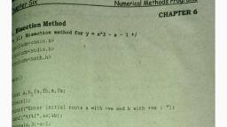
Page 1 :
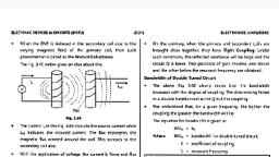
WHAT IS AN OSCILLATOR?, An oscillator is a circuit which produces a continuous, repeated, alternating, waveform without any input. Oscillators basically convert unidirectional current, flow from a DC source into an alternating waveform which is of the desired, frequency, as decided by its circuit components. The basic principle behind the, working of oscillators can be understood by analyzing the behavior of an LC tank, circuit shown in Figure 1 below, which employs an inductor L and a completely precharged capacitor C as its components. Here, at first, the capacitor starts to discharge, via the inductor, which results in the conversion of its electrical energy into the, electromagnetic field, which can be stored in the inductor. Once the capacitor, discharges completely, there will be no current flow in the circuit., , However, by then, the stored electromagnetic field would have generated a, back-emf which results in the flow of current through the circuit in the same, direction as that of before. This current flow through the circuit continues until the, electromagnetic field collapses which result in the back-conversion of, electromagnetic energy into electrical form, causing the cycle to repeat. However,, now the capacitor would have charged with the opposite polarity, due to which one, gets an oscillating waveform as the output.
Page 2 :
However, the oscillations which arise due to the inter-conversion between the two, energy-forms cannot continue forever as they would be subjected to the effect of, energy loss due to the resistance of the circuit. As a result, the amplitude of these, oscillations decreases steadily to become zero, which makes them damped in nature., This indicates that in order to obtain the oscillations which are continuous and of, constant amplitude, one needs to compensate for the energy loss. Nevertheless, it is, to be noted that the energy supplied should be precisely controlled and must be equal, to that of the energy lost in order to obtain the oscillations with constant amplitude., This is because, if the energy supplied is more than the energy lost, then the, amplitude of the oscillations will increase (Figure 2a) leading to a distorted output;, while if the energy supplied is less than the energy lost, then the amplitude of the, oscillations will decrease (Figure 2b) leading to unsustainable oscillations., , Practically, the oscillators are nothing but the amplifier circuits which are provided, with a positive or regenerative feedback wherein a part of the output signal is fed, back to the input (Figure 3). Here the amplifier consists of an amplifying active, element which can be a transistor or an Op-Amp and the back-fed in-phase signal is, held responsible to keep-up (sustain) the oscillations by making-up for the losses in, the circuit.
Page 3 :
Once the power supply is switched ON, the oscillations will be initiated in the system, due to the electronic noise present in it. This noise signal travels around the loop,, gets amplified and converges to a single frequency sine wave very quickly. The, expression for the closed-loop gain of the oscillator shown in Figure 3 is given as:, , G=, , A, 1 + Aβ, , Where A is the voltage gain of the amplifier and β is the gain of the feedback, network. Here, if Aβ > 1, then the oscillations will increase in amplitude (Figure 2a);, while if Aβ < 1, then the oscillations will be damped (Figure 2b). On the other hand,, Aβ = 1 leads to the oscillations which are of constant amplitude (Figure 2c). In other, words, this indicates that if the feedback loop gain is small, then the oscillation diesout, while if the gain of the feedback loop is large, then the output will be distorted;, and only if the gain of feedback is unity, then the oscillations will be of constant, amplitude leading to self-sustained oscillatory circuit.
Page 4 :
CLASSIFICATION OF OSCILLATORS, There are many types of oscillators, but can broadly be classified into two main, categories – Harmonic Oscillators (also known as Linear Oscillators) and Relaxation, Oscillators. In a harmonic oscillator, the energy flow is always from the active, components to the passive components and the frequency of oscillations is decided, by the feedback path. Whereas in a relaxation oscillator, the energy is exchanged, between the active and the passive components and the frequency of oscillations is, determined by the charging and discharging time-constants involved in the process., Further, harmonic oscillators produce low-distorted sine-wave outputs while the, relaxation oscillators generate non-sinusoidal (saw-tooth, triangular or square), wave-forms. Oscillators can be also be classified into various types depending on, the parameter considered i.e. based on the feedback mechanism, the shape of the, output waveform, etc. These classifications types have been given below:, 1. Classification Based on the Feedback Mechanism: Positive Feedback, Oscillators and Negative Feedback Oscillators., 2. Classification Based on the Shape of the Output Waveform: Sine Wave, Oscillators, Square or Rectangular Wave oscillators, Sweep Oscillators, (which produce saw-tooth output waveform), etc., 3. Classification Based on the Frequency of the Output Signal: Low-Frequency, Oscillators, Audio Oscillators (whose output frequency is of audio range),, Radio Frequency Oscillators, High-Frequency Oscillators, Very HighFrequency Oscillators, Ultra High-Frequency Oscillators, etc., 4. Classification Based on the type of the Frequency Control Used: RC, Oscillators, LC Oscillators, Crystal Oscillators (which use a quartz crystal to, result in a frequency stabilized output waveform), etc.
Page 5 :
5. Classification Based on the Nature of the Frequency of Output, Waveform: Fixed Frequency Oscillators and Variable or Tunable Frequency, Oscillators., , OSCILLATOR APPLICATIONS, Oscillators are a cheap and easy way to generate specific Frequency of a signal. For, example, an RC oscillator is used to generate a Low Frequency signal, an LC, oscillator is used to generate a High Frequency signal, and an Op-Amp based, oscillator is used to generate a stable frequency. The frequency of oscillation can be, varied by varying the component value with potentiometer arrangements. Some, common applications of oscillators include:, , , Quartz watches (which uses a crystal oscillator), , , , Used in various audio systems and video systems, , , , Used in various radio, TV, and other communication devices, , , , Used in computers, metal detectors, stun guns, inverters, ultrasonic and radio, frequency applications., , , , Used to generate clock pulses for microprocessors and micro-controllers, , , , Used in alarms and buzzes, , , , Used in metal detectors, stun guns, inverters, and ultrasonic, , , , Used to operate decorative lights (e.g. dancing lights), , The main types of Oscillators include:, , , Wien Bridge Oscillator, , , , RC Phase Shift Oscillator, , , , Hartley Oscillator
Page 6 :
, , Voltage Controlled Oscillator, , , , Colpitts Oscillator, , , , Clapp Oscillators, , , , Crystal Oscillators, , , , Armstrong Oscillator, , , , Tuned Collector Oscillator, , , , Gunn Oscillator, , , , Cross-Coupled Oscillators, , , , Ring Oscillators, , , , Dynatron Oscillators, , , , Meissner Oscillators, , , , Opto-Electronic Oscillators, , , , Pierce Oscillators, , , , Robinson Oscillators, , , , Tri-tet Oscillators, , , , Pearson-Anson Oscillators, , , , Delay-Line Oscillators, , , , Electron Coupled Oscillators, , , , Multi-Wave Oscillators, , BARKHAUSEN CRITERION, , , Conditions which are required to be satisfied to operate the circuit as an, oscillator are called as “Barkhausen criterion” for sustained oscillations., , , , The Barkhausen criteria should be satisfied by an amplifier with positive, feedback to ensure the sustained oscillations., , , , For an oscillation circuit, there is no input signal “Vs”, hence the feedback, signal Vf itself should be sufficient to maintain the oscillations., , , , The Barkhausen criterion states that:
Page 7 :
The loop gain is equal to unity in absolute magnitude, that is, | β A |=1, The phase shift around the loop is zero or 360₀ (OR an integer multiple, of 2π: ∠ β A = 2 π n, n ∈ 0, 1, 2…), The product β A is called as the “loop gain”., , HARTLEY OSCILLATOR, Hartley Oscillator is a type of harmonic oscillator which was invented by Ralph, Hartley in 1915. These are the Tuned Circuit Oscillators which are used to produce, the waves in the range of radio frequency and hence are also referred to as RF, Oscillators. Its frequency of oscillation is decided by its tank circuit which has a, capacitor connected in parallel with the two serially connected inductors, as shown, by
Page 8 :
Here the RC is the collector resistor while the emitter resistor RE forms the, stabilizing network. Further the resistors R1 and R2 form the voltage divider bias, network for the transistor in common-emitter CE configuration. Next, the capacitors, Ci and Co are the input and output decoupling capacitors while the emitter capacitor, CE is the bypass capacitor used to bypass the amplified AC signals. All these, components are identical to those present in the case of a common-emitter amplifier, which is biased using a voltage divider network. However, Figure 1 also shows one, more set of components viz., the inductors L1 and L2 and the capacitor C which form, the tank circuit (shown in red enclosure)., On switching ON the power supply, the transistor starts to conduct, leading to an, increase in the collector current, IC which charges the capacitor C. On acquiring the, maximum charge feasible, C starts to discharge via the inductors L1 and L2. This, charging and discharging cycles result in the damped oscillations in the tank circuit., The oscillation current in the tank circuit produces an AC voltage across the, inductors L1 and L2 which are out of phase by 180o as their point of contact is, grounded., Further from the figure, it is evident that the output of the amplifier is applied across, the inductor L1 while the feedback voltage drawn across L2 is applied to the base of, the transistor. Thus one can conclude that the output of the amplifier is in-phase with, the tank circuit’s voltage and supplies back the energy lost by it while the energy fed, back to amplifier circuit will be out-of-phase by 180o. The feedback voltage which, is already 180o out-of-phase with the transistor is provided by an additional 180o, phase-shift due to the transistor action. Hence the signal which appears at the, transistor’s output will be amplified and will have a net phase-shift of 360o., At this state, if one makes the gain of the circuit to be slightly greater than the, feedback ratio given by
Page 9 :
(if the coils are wound on the same core with M indicating the mutual inductance), then the circuit generates the oscillations which can be sustained by maintaining the, gain of the circuit to be equal to that of the feedback ratio. This causes the circuit in, Figure 1 to act as an oscillator as it would then satisfy both the conditions of the, Barkhausen criteria. The frequency of such an oscillator is given as, , Where,, , Hartley oscillators are available in many different configurations including series-or, shunt-fed, common-emitter or common-base configured, and BJT (Bipolar Junction, Transistor) or FET (Field Effect Transistor) amplifier based. Further it is to be noted, that the transistor-based amplifier section of Figure 1 can even be replaced by an, amplifier of any other kind like that of an inverting amplifier formed by an OpAmp as shown by Figure 2. The working of this kind of oscillator is similar to that, of the one shown earlier. However, here, the gain of the oscillator can be individually
Page 10 :
adjusted using the feedback resistor Rf due to the fact that the gain of the inverting, amplifier is given as -Rf / R1. From this, it can be noted that, in this case, the gain of, the circuit is less dependent on the circuit elements of the tank circuit. This increases, the stability of the oscillator in terms of its frequency., , Hartley Oscillators are advantageous as they are easy-tunable circuits with a very, few components including a capacitor and either two inductors or a tapped coil. This, results in a constant amplitude output throughout its wide operational frequency, range which typically ranges from 20 KHz to 30 MHz. However, this kind of, oscillator is not suitable for low frequency as it would result in a large-sized inductor, which makes the circuit bulky. Further, the output of Hartley Oscillator has high, content of harmonics in it and hence does not suit for the applications which require, pure sine wave.
Page 11 :
COLPITTS OSCILLATOR, Colpitts Oscillator is a type of LC oscillator which falls under the category of, Harmonic Oscillator and was invented by Edwin Colpitts in 1918. Figure 1 shows a, typical Colpitts oscillator with a tank circuit in which an inductor L is connected in, parallel to the serial combination of capacitors C1 and C2 (shown by the red, enclosure)., , Other components in the circuit are the same as that found in the case of commonemitter CE which is biased using a voltage divider network i.e. RC is the collector, resistor, RE is the emitter resistor which is used to stabilize the circuit and the
Page 12 :
resistors R1 and R2 form the voltage divider bias network. Further, the capacitors Ci, and Co are the input and output decoupling capacitors while the emitter capacitor CE, is, , the, , bypass, , capacitor, , used, , to, , bypass, , the, , amplified, , AC, , signals., , Here, as the power supply is switched ON, the transistor starts to conduct, increasing, the collector current IC due to which the capacitors C1 and C2 get charged. On, acquiring the maximum charge feasible, they start to discharge via the inductor L., During this process, the electrostatic energy stored in the capacitor gets converted, into magnetic flux which in turn is stored within the inductor in the form of, electromagnetic energy. Next, the inductor starts to discharge which charges the, capacitors once again. Likewise, the cycle continues which gives rise to the, oscillations in the tank circuit., Further the figure shows that the output of the amplifier appears across C1 and thus, is in-phase with the tank circuit’s voltage and makes-up for the energy lost by resupplying it. On the other hand, the voltage feedback to the transistor is the one, obtained across the capacitor C2, which means the feedback signal is out-of-phase, with the voltage at the transistor by 180o. This is due to the fact that the voltages, developed across the capacitors C1 and C2 are opposite in polarity as the point where, they join is grounded. Further, this signal is provided with an additional phase-shift, of 180o by the transistor which results in a net phase-shift of 360o around the loop,, satisfying the phase-shift criterion of Barkhausen principle., At this state, the circuit can effectively act as an oscillator producing sustained, oscillations by carefully monitoring the feedback ratio given by (C1 / C2). The, frequency of such a Colpitts Oscillator depends on the components in its tank circuit, and is given by
Page 13 :
Where, the Ceff is the effective capacitance of the capacitors expressed as, , As a result, these oscillators can be tuned either by varying their inductance or the, capacitance. However the variation of L does not yield a smooth variation. Hence, they are usually tuned by varying the capacitances which are generally ganged, due, to which a change in any one of them changes both of them. Nevertheless, the, process is tedious and requires special large-valued capacitor. Thus, the Colpitts, oscillators are seldom preferred in the applications where in the frequency varies but, are more popular as fixed frequency oscillators due to their simple design. Further, they offer better stability in comparison with the Hartley Oscillators as they are, exempted from the mutual inductance effect present in-between the two inductors of, the latter case.
Page 14 :
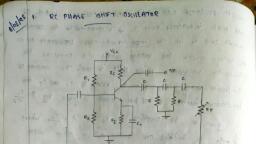
Apart from the BJT-based Colpitts Oscillator shown, they are also realizable using, valves or FET (Field Effect Transistor) or Op-Amp. Figure 2 shows such a Colpitts, oscillator which uses an Op-Amp in inverting configuration in its amplifier section, while the tank circuit remains similar to that in the case of Figure 1. This kind of, circuit functions almost analogous to that of the one explained earlier. However, here, the gain of the oscillator can be adjusted individually just by using the feedback, resistor Rf, as the gain of the inverting amplifier is given as -Rf / R1. From this, it can, be noted that, in this case, the gain of the circuit is less dependent on the circuit, elements of the tank circuit. Typically, the operating frequency of the Colpitts, oscillators ranges from 20 KHz to 300 MHz. However they can even be used for, microwave applications as their capacitors provide low reactance path for the highfrequency signals. This results in better frequency stability as well as a better, sinusoidal output waveform. Moreover, they are also extensively used as surface, acoustical wave (SAW) resonators, sensors and in mobile and communication, systems., , RC PHASE-SHIFT OSCILLATORS, RC phase-shift oscillators use resistor-capacitor (RC) network (Figure 1) to provide, the phase-shift required by the feedback signal. They have excellent frequency, stability and can yield a pure sine wave for a wide range of loads.
Page 15 :
Ideally a simple RC network is expected to have an output which leads the input by, 90o.However, in reality, the phase-difference will be less than this as the capacitor, used in the circuit cannot be ideal. Mathematically the phase angle of the RC network, is expressed as, , Where, XC = 1/(2πfC) is the reactance of the capacitor C and R is the resistor. In, oscillators, these kind of RC phase-shift networks, each offering a definite phaseshift can be cascaded so as to satisfy the phase-shift condition led by the Barkhausen, Criterion. One such example is the case in which RC phase-shift oscillator is, formed by cascading three RC phase-shift networks, each offering a phase-shift of, 60o, as shown by Figure 2.
Page 16 :
Here the collector resistor RC limits the collector current of the transistor, resistors, R1 and R (nearest to the transistor) form the voltage divider network while the, emitter resistor RE improves the stability. Next, the capacitors CE and Co are the, emitter by-pass capacitor and the output DC decoupling capacitor, respectively., Further, the circuit also shows three RC networks employed in the feedback path., This arrangement causes the output waveform to shift by 180 o during its course of, travel from output terminal to the base of the transistor. Next, this signal will be, shifted again by 180o by the transistor in the circuit due to the fact that the phasedifference between the input and the output will be 180 o in the case of common, emitter configuration. This makes the net phase-difference to be 360o, satisfying the, phase-difference condition. One more way of satisfying the phase-difference, condition is to use four RC networks, each offering a phase-shift of 45o. Hence it, can be concluded that the RC phase-shift oscillators can be designed in many ways, as the number of RC networks in them is not fixed. However it is to be noted that,, although an increase in the number of stages increases the frequency stability of the, circuit, it also adversely affects the output frequency of the oscillator due to the, loading effect. The generalized expression for the frequency of oscillations produced, by a RC phase-shift oscillator is given by, , Where, N is the number of RC stages formed by the resistors R and the capacitors, C. Further, as is the case for most type of oscillators, even the RC phase-shift, oscillators can be designed using an Op-Amp as its part of the amplifier section, (Figure 3). Nevertheless, the mode of working remains the same while it is to be
Page 17 :
noted that, here, the required phase-shift of 360o is offered collectively by the RC, phase-shift networks and the Op-Amp working in inverted configuration., , Further, it is to be noted that the frequency of the RC phase-shift oscillators can be, varied by changing either the resistors or the capacitors. However, in general, the, resistors are kept constant while the capacitors are gang-tuned. Next, by comparing, the RC phase-shift oscillators with LC oscillators, one can note that, the former, uses more number of circuit components than the latter one. Thus, the output, frequency produced from the RC oscillators can deviate much from the calculated, value rather than in the case of LC oscillators. Nevertheless, they are used as local, oscillators for synchronous receivers, musical instruments and as low and/or audiofrequency generators., , WIEN-BRIDGE OSCILLATOR, A Wien-Bridge Oscillator is a type of phase-shift oscillator which is based upon a, Wien-Bridge network (Figure 1a) comprising of four arms connected in a bridge, fashion. Here two arms are purely resistive while the other two arms are a, combination of resistors and capacitors. In particular, one arm has resistor and
Page 18 :
capacitor connected in series (R1 and C1) while the other has them in parallel (R2 and, C2). This indicates that these two arms of the network behave identical to that of, high pass filter or low pass filter, mimicking the behavior of the circuit shown by, Figure 1b., , In this circuit, at high frequencies, the reactance of the capacitors C 1 and C2 will be, much less due to which the voltage V0 will become zero as R2 will be shorted. Next,, at low frequencies, the reactance of the capacitors C1 and C2 will become very high., However even in this case, the output voltage V0 will remain at zero only, as the, capacitor C1 would be acting as an open circuit. This kind of behavior exhibited by, the Wien-Bridge network makes it a lead-lag circuit in the case of low and high, frequencies, respectively., , Wien Bridge Oscillator Frequency Calculation, Nevertheless, amidst these two high and low frequencies, there exists a particular, frequency at which the values of the resistance and the capacitive reactance will, become equal to each other, producing the maximum output voltage. This frequency
Page 19 :
is referred to as resonant frequency. The resonant frequency for a Wein Bridge, Oscillator is calculated using the following formula:, , Further, at this frequency, the phase-shift between the input and the output will, become zero and the magnitude of the output voltage will become equal to one-third, of the input value. In addition, it is seen that the Wien-Bridge will be balanced only, at this particular frequency. In the case of Wien-Bridge oscillator, the Wien-Bridge, network of Figure 1 will be used in the feedback path as shown in Figure 2. The, circuit diagram for a Wein Oscillator using a BJT (Bipolar Junction Transistor) is, shown below:
Page 20 :
In these oscillators, the amplifier section will comprise of two-stage amplifier, formed by the transistors, Q1 and Q2, wherein the output of Q2 is back-fed as an input, to Q1 via Wien-Bridge network (shown within the blue enclosure in the figure). Here,, the noise inherent in the circuit will cause a change in the base current of Q1 which, will appear at its collector point after being amplified with a phase-shift of 180o., This is fed as an input to Q2 via C4 and gets further amplified and appears with an, additional phase-shift of 180o. This makes the net phase-difference of the signal fed, back to the Wien-Bridge network to be 360o, satisfying phase-shift criterion to obtain, sustained oscillations., However, this condition will be satisfied only in the case of resonant frequency, due, to which the Wien-Bridge oscillators will be highly selective in terms of frequency,, leading to a frequency-stabilized design., Wien-bridge oscillators can even be designed using Op-Amps as a part of their, amplifier section, as shown by Figure 3. However it is to be noted that, here, the OpAmp is required to act as a non-inverting amplifier as the Wien-Bridge network, offers zero phase-shift. Further, from the circuit, it is evident that the output voltage, is fed back to both inverting and non-inverting input terminals., At resonant frequency, the voltages applied to the inverting and non-inverting, terminals will be equal and in-phase with each other. However, even here, the, voltage gain of the amplifier needs to be greater than 3 to start oscillations and equal, to 3 to sustain them. In general, these kind of Op-Amp-based Wien Bridge, Oscillators cannot operate above 1 MHz due to the limitations imposed on them by, their open-loop gain.
Page 21 :
Wien-Bridge networks are low frequency oscillators which are used to generate, audio and sub-audio frequencies ranging between 20 Hz to 20 KHz. Further, they, provide stabilized, low distorted sinusoidal output over a wide range of frequency, which can be selected using decade resistance boxes. In addition, the oscillation, frequency in this kind of circuit can be varied quite easily as it just needs variation, of the capacitors C1 and C2. However these oscillators require large number of circuit, components and can be operated up to a certain maximum frequency only., , QUESTIONS TO DO, 1. State and briefly explain Barkhausen Criteria for Oscillations., 2. What is an oscillator? What is its need? Discuss the advantages of oscillators., 3. What do you understand by damped and undamped electrical oscillations?, Illustrate your answer with examples., 4. Write short note on Crystal Oscillator., 5. Discuss the drawbacks associated with LC oscillators.