Notes of Msc 4 Op- Amplifier, Operational Amplifier op_amps.pdf - Study Material
Page 1 :
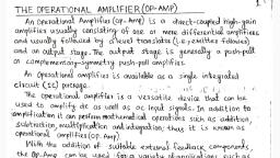
The Operational Amplifier, •, , The operational amplifier (“op amp”) is a basic building block used in, analog circuits., – Its behavior is modeled using a dependent source., – When combined with resistors, capacitors, and inductors, it can, perform various useful functions:, • amplification/scaling of an input signal, • sign changing (inversion) of an input signal, • addition of multiple input signals, • subtraction of one input signal from another, • integration (over time) of an input signal, • differentiation (with respect to time) of an input signal, • analog filtering, • nonlinear functions like exponential, log, sqrt, etc., , Anup, , 1
Page 2 :
Op Amp Circuit Symbol and Terminals, V+, non-inverting input, inverting input, , positive power supply, , +, output, , –, , V – negative power supply, , The output voltage can range from V – to V + (“rails”), The positive and negative power supply voltages do not have to, be equal in magnitude (example: 0V and +3V DC supplies), , Anup, , 2
Page 5 :
Achieving a “Virtual Short”, Recall the voltage transfer characteristic of an op-amp:, Plotted using different scales, for vo and vp–vn, , Plotted using similar scales, for vo and vp–vn, , vo, , vo, , Vcc, slope = A >>1, , ~10 V, , vp–vn, , -Vcc, , Vcc, slope = A >>1, , ~10 V, , vp–vn, , -Vcc, , ~1 mV, , ~10 V, , Q: How does a circuit maintain a virtual short at the input of an op-amp, to, ensure operation in the linear region?, , A: By using negative feedback. A signal is fed back from the output to, the inverting input terminal, effecting a stable circuit connection., Operation in the linear region enforces the virtual short circuit., Anup, , 5
Page 6 :
Negative vs. Positive Feedback, , Familiar examples of negative feedback:, • Thermostat controlling room temperature, • Driver controlling direction of automobile, • Pupil diameter adjustment to light intensity, , Familiar examples of positive feedback:, • Microphone “squawk” in sound system, • Mechanical bi-stability in light switches, , Anup, , Fundamentally, pushes toward, stability, , Fundamentally, pushes toward, instability or, bi-stability, , 6
Page 8 :
Op Amp Circuits with Negative Feedback, Q: How do we know whether an op-amp is operating in the linear region?, A: We don’t, a priori., • Assume that the op-amp is operating in the linear region and solve for vo in, the op-amp circuit., – If the calculated value of vo is within the range from -Vcc to +Vcc, then the, assumption of linear operation might be valid. We also need stability –, usually assumed for negative feedback., – If the calculated value of vo is greater than Vcc, then the assumption of, linear operation was invalid, and the op-amp output voltage is saturated at, Vcc., – If the calculated value of vo is less than -Vcc, then the assumption of linear, operation was invalid, and the op-amp output voltage is saturated at -Vcc., , Anup, , 8
Page 10 :
Ideal Op-Amp, , •, , •, , Assumptions:, – Ri is large (105 W), – A is large (104), – Ro is small (<100 W), , ip = –in= 0, vp = v n, , Simplified circuit symbol:, – power-supply terminals and, dc power supplies not shown, , Note: The resistances used, in an op-amp circuit must be, much larger than Ro and, much smaller than Ri in, order for the ideal op-amp, equations to be accurate., , ip, +, , +, in, +, , vp, –, Anup, , vn, –, , –, , io, +, vo, –, 10
Page 11 :
Unity-Gain Voltage-Follower Circuit, , VIN, , vp, , +, , , IIN, , vn, , V0(V), 2, 1, , V0, , vp = vn V0 = VIN, , 1, , 2, , VIN(V), , ( valid as long as V – V0 V + ), , Note that the analysis of this simple (but important) circuit required only, one of the ideal op-amp rules., Q: Why is this circuit important (i.e., what is it good for)?, A: A “weak” source can drive a “heavy” load; in other words, the source, VIN only needs to supply a little power (since IIN = 0), whereas the output, can drive a power-hungry load (with the op-amp providing the power)., , Anup, , 11
Page 12 :
What’s Inside an Op-Amp?, , Anup, , 12
Page 13 :
Lecture Week 8 (continued), , • Op-Amp circuits continued: examples:, •, •, •, •, •, , Inverting amplifier circuit, Summing amplifier circuit, Non-inverting amplifier circuit, Differential amplifier circuit, Current-to-voltage converter circuit, , Reading, (Note: amplifiers are discussed, in great detail in Ch. 11), , Anup, , 13
Page 14 :
Review: Negative Feedback, Negative feedback is used to “linearize” a high-gain differential amplifier., With feedback, , +, , , V, V+, , V0, , +, , , Without feedback, , VIN, , A 10 5, , V0(V), , 5, , V0, , V0, , 5, , 50μV, , A 105, , V V, , 5, 4, 3, 2, 1, 1 2345, , Anup, , VIN, , 14
Page 15 :
Gain vs. Frequency of the Basic Op-Amp without and, with Feedback (Hambley, Sec. 14.5), Facts:, 1. The open-loop gain of an op--amp (no feedback from output to inverting input), is constant from DC to a frequency fBOL, after which the open-loop gain drops at a rate of, -20dB/decade of frequency (Fig. 14.20 – next slide)., 2. As the negative feedback is made stronger, the gain decreases but the bandwidth, of the amplifier increases. (Bandwidth of an amplifier is the frequency range over which, it amplifies.), 3. One can show (Hambley) that the product of the dc gain and the bandwidth, is a constant that is independent of the amount of negative feedback. This is called the, gain-bandwidth product for the op-amp. Example: The op-amp you’ll use in the lab, (National Semiconductor LMC6482) is rather like that shown in Hambley Fig. 14.22,, with a DC open-loop gain of 100 dB (voltage amplification of 105) out to about only, 40 Hz! With negative feedback, however, the amplifier has an increasing bandwidth, but with decreasing gain. The unity gain (0 dB) bandwidth is 4 MHz; one can get, 40 dB of gain (Vout/Vin = 100) from DC to about 40 kHz., Anup, , 15
Page 16 :
Op-Amp Frequency Response with and without Negative Feedback, , Anup, , 16
Page 17 :
Application of Voltage Follower:, Sample and Hold Circuit, , Anup, , 17
Page 19 :
Analysis using Realistic Op-Amp Model, • In the analysis on the previous slide, the op-amp was assumed to, be ideal, i.e., Ri = ; A = ; Ro = 0, • In reality, an op-amp has finite Ri, finite A, non-zero Ro, and usually, is loaded at its output terminals with a load resistance RL., , Anup, , 19
Page 21 :
Application: Digital-to-Analog Conversion, A DAC can be used to convert the digital representation Binary Analog, number output, of an audio signal into an analog voltage that is then, (volts), used to drive speakers -- so that you can hear it!, 0000, 0, “Weighted-adder D/A converter”, S4, , 20K, , S2, , 40K, , 5K, , 80K, , , +, , +, -, , S1, , 4-Bit D/A, (Transistors are used, as electronic switches), , +, , , S3, , 8V, , 10K, , V0, , S1 closed if LSB =1, S2, " if next bit = 1, S3, " if " " = 1, S4, " if MSB = 1, Anup, , 0001, 0010, 0011, 0100, 0101, 0110, 0111, 1000, 1001, 1010, 1011, 1100, 1101, 1110, 1111, , MSB, , .5, 1, 1.5, 2, 2.5, 3, 3.5, 4, 4.5, 5, 5.5, 6, 6.5, 7, 7.5, , LSB 21
Page 22 :
Analog Output (V), , Characteristic of 4-Bit DAC, , 8, 7, 6, 5, 4, 3, 2, 1, 0, , 0000, , 0, , 2, 0001, , 4, 0100, , 6, , 8, , 10, , 1000, , Digital, Input, Anup, , 12, , 14, , 16, , 1111, 22
Page 25 :
Differential Amplifier (cont’d), More usual version of differential amplifier (Horowitz, & Hill, “Art of Electronics”, 2nd Ed., p. 184-5 (part of their, “smorgasbord” of op-amp circuits):, Let Ra = Rc = R1, and Rb = Rd = R2, Then v0 = (R2 / R1)(vb – va), To get good “common-mode rejection” (next slide), you need well-matched resistors (Ra and Rc,, Rb and Rd), such as 100kW 0.01% resistors, , Anup, , 25
Page 27 :
Differential Amplifier (cont’d), , Ra, Rc, Rb, If, , , then vcm 0 and vdm , Rb, Rd, Ra, • An ideal differential amplifier amplifies only the, differential mode portion of the input voltage, and, eliminates the common mode portion., – provides immunity to noise (common to both inputs), , • If the resistors are not perfectly matched, the common, mode rejection ratio (CMRR) is finite:, , Adm, 1 Rb / Ra, Ra, Rc, CMRR , , if, (1 ), Acm, , Rb, Rd, Anup, , 27
Page 28 :
Op-Amp Current-to-Voltage Converter, , Anup, , 28
Page 29 :
•, , Summary, Voltage transfer characteristic of op-amp:, vo, Vcc, slope = A >>1, , ~10 V, , vp–vn, , -Vcc, ~1 mV, , • A feedback path between an op-amp’s output and its, inverting input can force the op-amp to operate in its linear, region, where vo = A (vp – vn), • An ideal op amp has infinite input resistance Ri, infinite, open-loop gain A, and zero output resistance Ro. As a, result, the input voltages and currents are constrained:, vp = vn and ip = -in = 0, Anup, , 29
Page 34 :
Op-Amp Imperfections, Discussed in Hambley, pp. 651-665 (of interest if you need to, use an op-amp in a practical application!), Linear range of operation: Input and output impedances not, ideal values; gain and bandwidth limitations, (including gain-bandwidth product);, Nonlinear limitations: Output voltage swing (limited by, “rails” and more); output current limits; slew-rate, limited (how fast can the output voltage change:, 0.5V/ms for the 741 op-amp, to 6000V/ms for high, slew-rate op-amp); full-power bandwidth, , DC imperfections: Offset current (input currents don’t sum, exactly to zero); offset voltage; There are pins, (denoted offsets) for inputs to help control this., Anup, , 34
 Learn better on this topic