Page 2 :
Capacitance, , Single capacitor, completely filled with dielectric, , 1. If the separation between the plates of a capacitor is 5, mm. Then the area of the plate of a 3F parallel plate, capacitor is:, (a) 4.259 x 10⁹ m2 (b) 1.964 x 10⁹ m2, (c) 12.81 x 10⁹ m2 (d) 1.694 x 10⁹ m2, 2. A parallel plate condenser with oil (dielectric, constant = 2) between the plates has capacitance C. If, oil is removed, the capacitance of capacitor becomes:
Page 3 :
(a), , 2C, , (b) 2 C, , (c) C / 2, (d) C/2, 3. A parallel plate capacitor has a capacitance of 2 F., A dielectric slab of constant K = 5 is inserted between, the plates and the capacitor is charged to 100 Volt, and isolated then the new potential difference. If the, dielectric slab is removed, will be, (a) 250 V, (b) 500 V, (c) 100 V, (d) none of these, 4. Consider a parallel plate capacitor with plates 20 cm, by 20 cm and separated by 2 mm. The dielectric, constant of the material between the plates is 5. The, plates are connected to a voltage sources of 500V., The energy density of the field between the plates, will be close to:, (a) 2.65 J/m3, (b) 1.95 J/m3, 3, (c) 1.38 J/m, (d) 0.69 J/m3, 5. A parallel plate capacitor is charged and the charging, battery is then disconnected. If the plates of the, capacitor are moved further apart by means of, insulating handles, then which of the following is not, correct?, (a) The capacitance decreases, (b) The charge on the capacitor increases, (c) The voltage across the plates increases, (d) The electrostatic energy stored in the capacitor, increases, 6. The energy required to charge a parallel plate, condenser of plate separation d and plate area of, cross-section A such that the uniform electric field, between the plates is E, is, , 1, 0 E 2 Ad, 2, (c) 0 E 2 / Ad, (a), , 1, 0 E 2 / A.d, 2, (d) 0 E 2 Ad, (b), , 7. A parallel plate capacitor has a uniform electric field, E in the space between the plates. If the distance, between the plates is d and area of each plate is A, the, energy stored in the capacitor is, , 1, 0 E 2 Ad, 2, 1, (c) 0 E 2, 2, (a), , (b) 0 EAd, , (b) The change in energy stored is, , 1, 1, , CV 2 1, 2, K , , (c) The charge on the capacitor is not conserved, (d) The potential difference between the plates, decrease K times., 10. A parallel plate air capacitor has capacity ‘C’., distance of separation ‘V’ is applied between the, plates. Force of attraction between the plates of the, parallel plate air capacitor is:, , C 2V 2, (a), 2d 2, CV 2, (c), 2d, , C 2V 2, (b), 2d, CV 2, (d), d, , 11. A parallel plate condenser with a dielectric of, dielectric constant K between the plates has a, capacity C and is charged to a potential V volt. The, dialectic slab is slowly removed from between the, plates and then reinserted. The net work done by the, system in this process is, (a) zero, (c), , (b), , CV 2 (K 1), K, , 1, (K 1) CV 2, 2, , (d) (K 1) CV 2, , 12. A parallel plate capacitor with plates of area 1m2, each. Area t a separation of 0.1 m. If the electric field, between the plates is 100 N/C, the magnitude of, charge each plate is, 10, 10, (a) 7.85 10 C (b) 6.85 10 C, 10, 10, (c) 9.85 10 C (d) 8.85 10 C, 13. A capacitor with capacitance 5 F is charged to, 5 C. If the plates are pulled apart to reduce the, capacitance to 2 F. How much work is done?, (a) 3.75 10 J (b) 2.55 10 J, 6, 6, (c) 2.16 10 J, (d) 6.25 10 J, 14. Fig. shows charge (q) versus voltage (V) graph for, series and parallel combination of two given, capacitors. The capacitances are:, 6, , 6, , (d) E 2 Ad / 0, , 8. In a parallel-plate capacitor with plate area A and, charges Q, the force on one plate because of the, charge on the other is equal to., (a), , Q2, 0 A2, , Q2, (c), 0 A, , (b), , Q2, 2 0 A2, , Q2, (d), 2 0 A, , 9. A parallel plate air capacitor of capacitance C is, connected to a cell of emf V and then disconnected, from it. A dielectric slab of dielectric constant K,, which can just fill the air gap of the capacitor, is now, inserted in it. Which of the following is incorrect?, (a) The energy stored in the capacitor decreases K, times, , (a) 50 F and 30 F, (b) 20 F and 30 F, (c) 60 F and 40 F, (d) 40 F and 10 F, 15. The electrostatic force between the metal plates of an, isolated parallel plate capacitor C having a charge Q, and area A, is:(a) Independent of the distance between the, plates., (b) Linearly proportional to the distance between, the plates
Page 4 :
(c) Proportional to the square root of the distance, between the plates., (d) Inversely proportional to the distance, between the plates., 16. The electric field intensity between the plates of a, parallel plate capacitor is uniform and equal to E., Then the work done in carrying charge q around a, closed rectangular contour, A B C D A is:, +A, +, +, +, +, +, +, +, +, +, +, +, +, + D, , (a) qE, (c) 4 qE, , E, , E, , B C -, , (b) 2 qE, (d) zero, , Combination of capacitors & charging, , 17. Two condensers of capacity C1 and C2 are connected, in parallel. If a charge Q is given to the assembly, the, charge gets shared. The ratio of the charge on the, condenser C1 to the charge on the condenser C2 is:, (a) C1/C2, (b) C2/C1, (c) C1C2/1, (d) 1/C1C2, 18. Four metallic plates, each with a surface area of one, side A, are placed at a distance d from each other., The alternate plates are connected to points A and B, as shown in fig. Then the capacitance of the system, is:, , 0 A, d, 3 0 A, (c), d, (a), , 2 0 A, d, 4 0 A, (d), d, (b), , 19. Two condensers of capacity 0.3 F and 0.6 F, respectively are connected in series. The combination, is connected across a potential of 6 volts. The ratio of, energies stored by the condensers will be:, (a) ½, (b) 2, (c) ¼, (d) 4, 20. A potential difference V is applied across two, capacitors of capacitances C1 and C2 connected in, series. Then the potential difference across C 1 will be:, , VC2, C1, VC2, (c), C1 C2, (a), , V (C1 C2 ), C1, VC1, (d), C1 C2, (b), , 21. A parallel combination of two air filled parallel plate, capacitors of capacitance C and nC is connected to a, battery of voltage, V. When the capacitor are fully, charged, the battery is removed and after that a, dielectric material of dielectric constant K is placed, between the two plates of the first capacitor. The new, potential difference of the combined system is
Page 5 :
V, K n, (n 1) V, (c), (K n), (a), , (b) V, (d), , nV, K n, , 22. Three equal capacitors, each with capacitance C are, connected as shown in the adjoining figure. Then the, equivalent capacitance between A and B is:, , 100 , C, 9 , (b) qb qd q f 0, (a) qb qd q f , , (c) qa qc qe 50C, (a) C, (b) 3C, (c) C/3, (d) 3C/2, 23. Three capacitors each of capacitance 1 F are, connected in parallel. To this combination, a fourth, capacitor of capacitance 1 F is connected in series., The resultant capacitance of the system is:, (a) 4 F, (b) 2 F, , (c) (4/3) F, (d) (3/4) F, 24. In the diagram below are shown three capacitors C1,, C2 and C3 joined to battery. With symbols having, their usual meanings, the correct conditions will be:, , (d) qb qd q f, , 28. Four capacitors each of 50 F capacitance and one, capacitor of 10 F are connected with 100 V battery, as shown in figure. The net capacitance between A, and B is:, 50F, , 50F, , A, , 10F, , 50F, , B, , 50F, , 100V, , (a) 50 F, (b) 60 F, (c) 110 , (d) 200 F, 29. Six equal capacitors each of capacitance C are, connected as shown in the figure. The equivalent, capacitance between A and B is:, , (a) Q1 Q2 Q3 and V1 V2 V3 V, (b) Q1 Q2 Q3 and V V1 V2 V3, (c) Q1 Q2 Q3 and V V1 V2, (d) Q3 Q2 and V2 V3, 25. Three capacitors of capacitances 3 F, 9 F and, 18 F are connected once in series and another time, in parallels. The ratio of equivalent capacitances in, the two cases (Cv/Cp) will be:, (a) 1 : 15, (b) 15 : 1, (c) 1 : 1, (d) 1 : 3, 26. Five equal capacitors, each with capacitance C are, connected as shown in the adjoining figure. Then the, equivalent capacitance between A and B is:-, , (a) C, (b) 5C, (c) C/5, (d) 3C, 27. Three capacitors are connected to a D.C source of, 100 volts as shown in the following figure. If the, charges accumulated on the plates of C1, C2 and C3, are qa, qb, qc, qd, qc, qf respectively then:, , (a) C/2, (b) 2C, (c) C, (d) 6C, 30. The equivalent capacity between points A and B as, shown in figure is:, 2F, , A, 8F, , 4F, , 1F, , 1F, , 4F, , (a) 10 F, (b) 20 F, (c) 5 F, (d) 2.5 F, 31. The equivalent capacity between point A and B, shown in the figure given below is:, , B
Page 6 :
36. Two condensers, one of capacity C and the other of, capacity, , C, , are connected to a V-volt battery, as, 2, , shown., (a) 3 F, (b) 1.5 F, (c) 6 F, (d) 9 F, 32. Five capacitors, each of capacitance value C are, connected as shown in the figure. The ratio of, capacitance between P and R and the capacitance, between P and Q is, , (a) 3 : 1, (b) 5 : 2, (c) 2 : 3, (d) 1 : 1, 33. What is the potential difference between A and B in, the circuit shown in the figure?, , The work done in charging fully both the condensers, is:, , 1, CV 2, 2, 1, 2, (c) CV, 4, , (b) 2CV 2, , (a), , (d), , 37. A series combination of n1 capacitors, each of value, C1, is charge by a source of potential difference 4V., When another parallel combination of n2 capacitors,, each of value C2 is charged by a source o potential, difference V, it has the same (total) energy stored in, it, as the first combination has. The value of C 2, in, terms of C1, is then., , 16C1, n1n2, n, (d) 16 2 C1, n1, , n2, C1, n1, 2C1, (c), n1n2, (a) 2, , (a) 1V, (b) 0 V, (c) 2 V, (d) none of these, 34. A 600 pF capacitor is charged by 200V supply. It is, then disconnected from the supply and is connected, to another 300 pF capacitor. The electrostatic energy, lost in the process is., (a) 0, (b) 4 x 10⁻⁶ J, 6, (c) 6 x 10 J, (d) 8 x 10⁻⁶ J, 35. Two identical capacitors C1 and C2 are connected as, shown in the figure with a battery B. A dielectric slab, is slipped between the plates of the capacitor C2, the, battery remaining connected. Consider the following, changes in the charges on the capacitors and the, potential difference across their plates., , 3, CV 2, 4, , (b), , 38. A capacitor is charged by a battery. The battery is, removed and another identical uncharged capacitor is, connected in parallel. The total electrostatic energy of, resulting system:, (a) Decreases by a factor of 2, (b) Remains the same, (c) Increases by a factor of 2, (d) Increases by a factor of 4, 39. The effective capacity between A and B in the figure, given is:- (in F), 2, , 3, , A, , 4, , 4, , B, , 2, , (a), (i) Increase in the value of charge on C1, (ii) Increase in the value of charge on C2, (iii) Increase in the value of p.d. across the plates of, C1, (iv) Decrease in the value of p.d. across the plates of, C2 which of the above is true?, (a) i,ii,iii and iv, , (b) ii only, , (c) ii and iv only, , (d) i and iv only, , 43, 24, , (b), , 24, 43, , 3, , (c), , 43, 12, , (d), , 12, 43, , 40. Five capacitors of 10 F capacity each are connected, to a DC potential of 100 volts as shown in figure. The, equivalent capacitance between the point A and B, will be equal to:-
Page 7 :
A 0, 6d, 3 A 0, (c), 4d, , A 0, 4d, A 0, (d), 3d, , (a), , (a) 40 F, (b) 20 F, (c) 30 F, (d) 10 F, 41. All the six capacitors shown in the circuit are, identical. Each can withstand maximum 200 volt, between its terminals. The maximum voltage that can, be applied safely between A & B is:-, , (a) 800 V, (b) 400 V, (c) 1200 V, (d) 200 V, 42. A capacitor of capacitance 160 F is charged to a, potential difference of 200 volt & then connected, across the discharged tube which conducts until the, potential difference across it has fallen to 100 volt., The energy dissipated in the tube is:(a) 6.4 J, (b) 4.8 J, (c) 4.2 J, (d) 2.4 J, 43. The effective capacitance between A and B is, (capacitance of each capacitor is C):-, , (b), , 45. In network as shown in the figure point A is, connected to earth. Potential at point B will be equal, to:-, , (a) -50V, (b) +50 V, (c) -30 V, (d) +30 V, 46. Two identical capacitors C1 and C2 of equal, capacitance are connected as shown in the circuit, terminals a and b of the key k are connected to charge, capacitor C1 using battery of emf V volt. Now, disconnecting a and b the terminals b and c are, connected. Due to this, what will be the percentage, loss of energy?, k, , c, , a, , b, V, C, , C2, , (a) 75%, (b) 0%, (c) 50%, (d) 25%, 47. In the figure shown below, the charge on the left plate, of the 10 F capacitor is -30 C. The charge on the, right plate of the 6 F capacitor is:, , (a) C, (c), , 36C, 17, , C, 2, 42C, (d), 17, (b), , 44. Four identical metal plates of area A and speration as, shown are arranged then calculate the effective, capacitance between A and B., , (a) -18 C, (b) -12 C, , (c) +12 C, (d) +18 C, 48. Seven capacitors, each of capacitance 2 F, are to be, connected in a configuration to obtain an effective, , 6, F . Which of the combinations, 13 , , capacitance of , , shown in figures below, will achieve the desired, value?
Page 8 :
d, 49. In the figure shown, after the switch ‘S’ is turned, from position ‘A’ to position ‘B’, the energy, dissipated in the circuit in terms of capacitance ‘C’, and total charge ‘Q’ is:, , 3 Q2, (a), 8 C, 1 Q2, (c), 8 C, , 3 Q2, (b), 4 C, 5 Q2, (d), 8 C, , 50. In the circuit shown, find C if the effective, capacitance of the whole circuit is to be 0.5 F. All, values in the circuit are in F., , 7, F, 10, 6, F, (c), 5, (a), , (b), , 7, F, 11, , (d) 4 F, , repeated, 51. In the given circuit, the charge, on 4 F capacitor will be:(a) 5.4 C, (b) 24 C, (c) 13.4 C(d) 9.6 C, Dielectric effect, partially filled dielectric, , 52. The area of the plates of a parallel plate condenser is, 100 cm2. The paper (K = 2.5) of thickness 0.005 cm, is put in between the plates. If the paper can tolerate a, field of 5 x 10⁷ volts/m, the maximum potential, difference upto which the condenser can be charged, is:(a) 2500 volts, (b) 7500 volts, (c) 500 volts, (d) 10000 volts, 53. Two identical parallel plate capacitors, of, capacitance C each, have plates of area A, separated, by a distance d. The space between the plates of the, two capacitors, is filled with three dielectrics, of, equal thickness and dielectric constants K1, K2 and, K3. The first capacitor is filled as shown in fig. and, the second one is filled as shown in fig., , If these two modified capacitors are charged by the, same potential V, the ratio of the energy stored in the, two, would be (E1 refers to capacitor (I) and E2 to, capacitor (II)):, , E1, E2, E, (b) 1, E2, E, (c) 1, E2, E, (d) 1, E2, (a), , 9 K1 K 2 K 3, (K1 K 2 K 3 )(K 2 K 3 K 3K1 K1K 2 ), K1 K 2 K 3, , (K1 K 2 K 3 )(K 2 K 3 K 3K1 K1K 2 ), (K K 2 K 3 )(K 2 K 3 K 3K1 K1K 2 ), 1, K1 K 2 K3, (K K 2 K 3 )(K 2 K 3 K 3K1 K1K 2 ), 1, 9 K1 K 2 K3, , , 54. The potential gradient at which the dielectric of the, condenser just gets punctured, is called:, (a) Dielectric constant, (b) Dielectric strength, (c) Dielectric resistance, (d) Dielectric number, 55. A parallel plate air capacitor has a capacitance of, 100 pF. The plates are at a distance d apart. A slab of, thickness t(t<d) and dielectric constant 5 is, introduced between the parallel plates. Then the, capacitance can be:, (a) 50 pF, (b) 100 pF, (c) 200 pF, (d) 500 pF, 56. A parallel plate condenser is filled with two, dielectrics as shown in fig. Area of each plate is A, metre2 and the separation is t metre. The dielectric, constant are K1 and K2 respectively. Its capacitance in, farad will be:, , (a), , 0 A, t, , (K1 K 2 ) (b), , 0 A (K1 K 2 ), t, , 2
Page 9 :
(c), , 0 A, t, , 2(K1 K 2 ) (d), , 0 A (K1 K 2 ), t, , 2, , 57. A parallel plate capacitor with air as medium, between the plates has a capacitance of 10 F. The, capacitor is divided into two halves and filled with, two media as shown in the figure having dielectric, constants K1 = 2 and K2 = 4. The capacitance of the, system will now:, , (a) 10 F, (b) 20 F, (c) 40 F, (d) 30 F, 58. A parallel plate condenser with plate area A and, separation t is filled with dielectrics as shown. The, dielectric constants are K1 and K2 respectively. The, capacitance will be:, , (a) C/2, (b) 2C, (c) 0, (d) infinite, 63. A capacitor of 1 F withstands a maximum voltage, of 6 kilovolts while another capacitor of 2 F, withstands a maximum voltage of 3 kilovolts. If the, two capacitors are connected in series, the system, will withstand a maximum voltage of:, (a) 2 kV, (b) 4 kV, (c) 6 kV, (d) 9 kV, 64. A parallel plate capacitor with air as the dielectric, has capacitance C. A slab of dielectric constant K and, having the same thickness as the separation between, the plates is introduced so as to fil one-fourth of the, capacitor as shown in the figure. The new capacitance, will be, , (a) (K 2), , 0 A, , (K1 K 2 ) (b), , 0 A K1 K 2 , , , , t K1K 2 , 2 0 A K1K 2 , 2 0 A K1 K 2 , (c), , , (d), , t K1 K 2 , t K1K 2 , (a), , t, , 59. Separation between the plates of a parallel plate, capacitor is d and the area of each plate is A. When a, slab of material of dielectric constant K and thickness, t is introduced between the plates, its capacitance, becomes:, (a), , 0 A, , (b), , 0 A, , 1, 1, , , d t 1 , d t , K, K, 0 A, 0 A, (c), (d), 1, 1, , , d t 1 , d t 1 , K, K, 60. Two capacitors each having capacitance C and, breakdown voltage V are joined in series. The, capacitance and the breakdown voltage of the, combination will be, (a) 2C and 2V, (b) C/2 and V/2, (c) 2C and V/2, (d) C/2 and 2V, 61. If the capacitors in the previous question are joined, in parallel, the capacitance and the breakdown, voltage of the combination will be:, (a) 2C and 2V, (b) C and 2V, (c) 2C and V, (d) C and V, 62. A thin metal plate P is inserted between the plates of, a parallel-plate capacitor of capacitance C in such a, way that its edges touch the two plates (figure). The, capacitance now becomes:, , (c), , KC, 4, , C, 4, , C, 4, C, (d) (K 1), 4, (b) (K 3), , 65. A slab of material of dielectric constant K has the, same area as the plates of a parallel plate capacitor, , 3, d. Where d is the separation, 4, , but has a thickness , , of the plates. The ratio of the capacitance C (in the, presence of the dielectric) to the capacitance C 0 (in, the absence of the dielectric) is:, , 3K, K 4, 4K, (c), K 3, (a), , 3, K, 4, 4, K, (d), 3, (b), , 66. Three capacitors each of capacitance C and of, breakdown voltage V are joined in series. The, capacitance and breakdown voltage of the, combination will be:, , C V, ,, 3 3, C, , 3V, (c), 3, (a), , (b) 3C ,, , V, 3, , (d) 3C, 3V, , 67. Two thin dielectric slabs of dielectric constants K1, and K2 (K1 < K2) are inserted between plates of a, parallel plate capacitor, as shown in the figure. The, variation of electric field ‘E’ between the plates with, distance ‘d’ as measured from plate P is correctly, shown by
Page 10 :
1 1 1 1, 3, , k k1 k2 k3 2k4, (b) k k1 k2 k3 3k4, 2, (c) k (k1 k 2 k 3 ) 2 k1, 3, 2, 3, 1, , , (d), k k1 k2 k3 k4, (a), , 69. A parallel plate capacitor is of area 6cm2 and a, separation 3mm. The gap is filled with three, dielectric materials of equal thickness (see figure), with dielectric constants K1 = 10, K2 = 12 and K3 =, 14. The dielectric constant of a material which when, fully inserted in above capacitor, gives same, capacitance would be:, , 68. A parallel-plate capacitor of area A, plate separation, d and capacitance C is filled with four dielectric, materials having dielectric constants k1, k2, k3 and k4, as shown in the figure below. If a single dielectric, material is to be used to have the same capacitance C, in this capacitor. Then its dielectric constant k is, given by, , (a) 12, (b) 4, (c) 36, (d) 14, 70. Voltage rating of a parallel plate capacitor is 500V., Its dielectric can withstand a maximum electric field, of 106 V/m. The plate area is 10-4 m2. What is the, dielectric constant if the capacitance is 15 pF?, (given 0 8.86 1012 C 2 / Nm2 ), (a) 3.8, (b) 4.5, (c) 6.2, (d) 8.5
Page 11 :
Electrodynamics, , Lecture 1, (c)Its specific resistance will increase, (d) Its specific resistance, 2.If n, e, t and m are respectively the density, charge,, relaxation time and mass of an electron then the, resistance of wire of length l and cross-sectional area, A, will be, 2 ml, ne 2 A, ne 2 A, m 2 A, (a), (b), (c), (d), 2 ml, 2ml, ne l, ne 2A, , 3. When the current i is flowing through a conductor,, the drift velocity is v . If 2i current is flowed, through the same metal but having double the, area of cross-section, then the drift velocity will, be, (a) v / 4, (b) v / 2, (c) v, (d) 4v, 4. The specific resistance of the material of a wire is , and its volume is 3 m3 and its resistance is 3. The, length of the wire will be, 3, 1, 3, , (a), (b), (c), (d), , , 3, , 5. If the length of wire is increased n times by stretching, it, then its resistance will become, (a) n times (b)n²times (c) 1/n times (d) 1/n² times, , Current, drift speed, Ohms law,, temperature effect, colour code, 1. On decreasing the length and radius of a conductor,, its resistance will, (a) Increase, (b)Decrease, , 6. A current of 1 mA is flowing in a copper wire. The, number of electrons crossing any point in the, conductor per second will be, (a) 6.25x1031(b) 6.25x10⁸(c) 6.25x10¹⁵(d) 6.25x10¹⁹, 7.If Ohm’s law is presumed to be valid, then drift velocity, Vd and electric field E are related as, (a) Vd E² (b) Vd E (c) Vd E (d) Vd E0, 8. Ohm’s law is valid for, (a)only metallic conductors, (c)non-metallic conductors, , (b) insulators, (d) any conductors
Page 12 :
9. The specific resistance of the material of a condenser, depends on its, (a) temperature (b)length (c) radius (d) size, 10. The resistance of a conductor is 60 . The curve, between log V and log I will be, (a) circle (b) hyperbola (c) straight line (d) parabola, , become respectively:, (a) 1.1 times, 1.1 times, (b) 1.2 times, 1.1 times, (c) 1.21 times, same, (d) both remain the same, 0, , 18. An electron is moving on a circle of radius 0.5 A with a, 11. The ohmic curve out of the following is, frequency of 5 x 10¹⁶ Hz in anti-clockwise direction., V, I, The equivalent loop-current is:, (a) 4.0 mA (clockwise), (b) 4.0 mA (anti-clockwise), V, (a), (b), (c) 8.0 mA (clockwise), (d) 8.0 mA (anti-clockwise), I, I, 19. A colour coded carbon resistor has the colours, orange, blue, green and silver. Its resistance value and, tolerance percentage respectively are:, (c), (d), V, V, (a) 36 x 105 and 10%, (b) 36 x 104 and 5%, (c) 63 x 105 and 10%, 12. The IV curve for a V, (d) 35 x 106 and 5%, conductor is as shown 8, 20. Across a metallic conductor of non-uniform cross, in the figure. The 7, section a constant potential difference is applied. The, 6, resistance, of, the 5, quantity which remains constant along the conductor, 4, conductor will be, is:, 3, (a) 1 (b) 3 , 2, (a) current, (b) drift velocity, 1, (a) 2 (d) 4 , (c), electricfield, (d) current density, i, 13.If a copper wire is 0 1 2 3 4 5 6 7, 21. A carbon resistor ( 47 4.7 )k is to be marked with, stretched to increase its length by 0.1% then, rings of different colour for its identification. The, percentage increase in its resistance will be, colour code sequence will be:(a) 0.2%, (b) 2%, (c) 1%, (d) 0.1%, (a) Violet – Yellow – Orange – Silver, 14.In copper each atom releases one electron. If a, (b) Yellow – Violet – Orange – Silver, current of 1.1 A is flowing in the copper wire of, (c) Yellow – Green – Violet – Gold, diameter 1 mm then the drift velocity of electrons, (d) Green – Orange – Violet – Gold, , will approximately be, , (density of copper = 9x10³ kgm3 and is atomic weight, = 63), (a) 10.3 mm/s (b)0.1mm/s (c) 0.2 mm/s (d) 0.2 cm/s, 15. An aluminium rod and a copper rod are taken such, that their lengths are same and their resistances are, also same. The specific resistance of copper is half, that of aluminium, but its density is three times that of, aluminium. The ratio of the mass of aluminium rod, and that of copper rod will be, (a) 1/6, (b) 2/3, (c)1/3, (d) 6, 16., , A conductor, C, F, with, rectangular, cross-section has, 2a, B, dimensions (a x A, 4a, 2a x 4a) as, shown in the, figure., E, D, Resistance, across AB is x, across CD is y and across EF is z., Then, (a) x = y = z (b) x > y > z (c) y > z > x (d) x > z > y, , 17. A wire of a certain material is stretched slowly be ten, per cent. Its new resistance and specific resistance, , 22. A 2W carbon resistor is color coded with green,, black, red respectively. The maximum current which, can be passed through this resistor is:, (a) 63 mA, (b) 0.4 mA, (c) 100 mA, (d) 20 mA, 23. A carbon resistance has a following colour code., What is the value of the resistance?, , (a) 1.64 M 5% (b) 530 k 5%, (c) 64 k 10% (d) 5.3 M 5%, 24. A resistance is shown in the figure. Its value and, tolerance are given respectively by:, , (a) 27 K , 20% (b) 270 K , 5%, (c) 270 K , 10% (d) 27 K , 10%, 25. A copper wire is stretched to make it 0.5% longer., The percentage change in its electrical resistance if its, volume remains unchanged is:, (a) 2.5%, (b) 0.5 %, (c) 1.0 %, (d) 2.0 %
Page 13 :
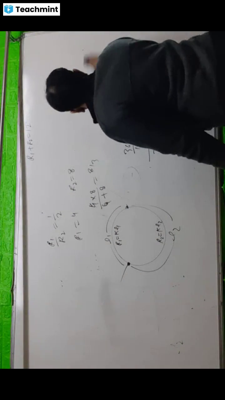
26. Drift speed of electrons, when 1.5A of current flows, in a copper wire of cross section 5 mm2, is v. If the, electron density in copper is 9 x 1028/m3 the value of v, in mm/s is close to (Take charge of electron to be =, 1.6 x 10⁻¹⁹C), (a) 0.2, (b) 3, (c) 2, (d) 0.02, 27. A 200 resistor has a certain color code. If one, replaces the red color by green in the code, the new, resistance will be:, (a) 100 , (b) 400 , (c) 500 , (d) 300 , 28. In a conductor, if the number of conduction electrons, per unit volume is 8.5 x 1028 m-3 and mean free time, is 25 fs (femto second), it’s approximate resistivity is, (me = 9.1 x 10⁻³¹ kg), (a) 10-5 m, (b) 10-6 m, -7, (c) 10 m, (d) 10-8 m, 29. The charge on a capacitor plate in a circuit, as a, function of time, is shown in the figure:, What is the value of current at t = 4 s?, , (a) 3 A, (c) zero, , (b) 2 A, (d) 1.5 A, , r, A, , 30. The charge (q) flowing in a conductor varies with, time t as q = ar bt². Then the current, (a) decreases linearly with time, (b) increases linearly with time, (c) first increases, reaches a maximum and then, decreases, , Effective Resistance, 31. There are n similar conductors each of resistance R., The resultant resistance comes out to be X when, connected in parallel. Then on connecting these in, series, the resistance will come out:, (a) X / n 2, (b) n 2 X, (c) X / n, (d) nX, , 32.The equivalent resistance between points X and Y, in the following diagram, will be, 4, 4, (a), (b), (c), (d), , 10.6 , 20 , 16 , 8, , 4, , 4Ώ, , 4, X, , 33. The equivalent resistance, between the points X and Y in, the following circuit will be, (a) R/4, (c) R/5, , 34. The equivalent resistance, between the points X and Y, 10, in the adjoining circuit will 10, X, be, (a) 10 (b) 40 , Y, (c) 30 , (d) 20 , ., 10, 10, 35. When two resistances are, connected in parallel then the equivalent resistance is, 6/5 . When one of the resistances is removed then, the effective resistance is 2 . The resistance of the, wire removed will be, (a) 3 , (b) 2 , (c) 3/5 , (d)6/5 , 36. If a wire of resistance R is cut into n equal parts and, the parts are connected in parallel then the equivalent, resistance of the combination will be, (a) R = nR² (b) R = R/n (c) R = n/R (d) R = R/n², 37. Four similar resistance wires, each of resistance 10 ,, from a square shape. The equivalent resistance, between two diagonally opposite ends will be, (a) 20 (b) 5 , (c)10 , (d)100, 38. Two resistances r1 and r2 are connected in parallel., The correct relation for equivalent resistance R will, be, (a) R < r1, (b) R > (r1 + r2), (c) r2 < R < r1 + r2, (d) r1 < R < r1, 39.The equivalent resistance between points A and B in, the given circuit will be, , (b) R/2, (d) R., , r, , (a) r, , r, , r, , r r, , r r, , r, , r, , r, , r r, , r r, , r, , (b) 2 r, , (c) 4/3 r, , 40.If, the, equivalent, resistance between the, points P and Q in the, following circuit is 5, , then the value of R, will be, (a) 5 , (b) 7 , (c) 9 , (d) 11 , , P, , R, R, , X, , R, , Y, R, , (d) 4 r, , R, , Q, R, R, , R, , R, R, , 41. A wire of resistance 10 is bent in the middle at, 180°. Its two halves are mutually connected together., Its new resistance will be, (a) 10 (b) 30 , (c) 50 , (d) 2.5, 42. A wire of resistance 12 ohms per meter is bent to, form a complete circle of radius 10 cm. The, resistance between its two diametrically opposite, points, A and B as shown in the figure, is:, , Y, , R, , B, , (a) 0.6 , (c) 6 , , (b) 3, (d) 6
Page 14 :
43. Two metal wires of identical dimensions are, connected in series. If 1 and 2 are the, conductivities of the metal wires respectively, the, effective conductivity of the combination is:, , 1 2, 1 2, 2, (c) 1, 2 1 2, (a), , 44., , (b), (d), , 2 1 2, 1 2, 1 2, , (a) 30 I1 41I3 45 0 and 30I1 2I 2 80 0, (b) 30 I1 41I3 45 0 and 30 I1 21I 2 80 0, (c) 30 I1 41I3 45 0 and 30 I1 21I 2 80 0, , 1 2, , A ring is made of a wire having a resistance, R0 12 . Find the points A and B, as shown in the, figure, at which a current carrying conductor should, be connected so that the resistance R of the sub, circuit between these points is equal to 8 / 3 ., , (d) 30 I1 41I3 45 0 and 30I1 21I 2 80 0, 47.The current flowing in, the following circuit, will be, (a) 0, (b) 0.6 A, (c) 1 A, (d) 1.5A, , i, , C, , D, 6, , 4, , 4, E, , B, 15V, A, , l1 3, l, l 5, 1, (b) 1 (c) 1 , l2 8, l2 2, l2 8, , l1 1, , l2 3, 45. A uniform metallic wire has a resistance of 18 and, (a), , (d), , is bent into an equilateral triangle. Then, the, resistance between any two vertices of the triangle is:, [JEE Mains-2019], (a) 8 , (b) 12 , (c) 4 , (d) 2 , , Electric Circuit ,Ideal voltameter,ammeter &, galvanometer, , 48.The potential difference, between the points X and, Y is the adjoining, diagram will be, (a) 2 V, (b) 4 V, (c) 6 V, (d) 8 V, , F, X, 3, , 3A 3, , 2, , 1, , Y, , 49.The reading of the ideal, voltmeter in the adjoining, diagram will be, (a) 4 V, (b) 8 V, (c) 12 V, (d) 14 V, 50.The potential difference, between points X and Y in, the following circuit will be, , 5V, , 2, , A, , 10V, , B, , 20, , V, , 10, , C, , N, , 4V, , 10V, r1, , 25, X, 0.1A, 15, , (a) 1 V, (c) 3 V, , Single choice questions, 46. For the current loops shown in the figure, Kirchhoff’s, loop rule for the loops AHDCBA and AHDEFGA, yields these equal, respectively:, , (b) 2 V, (d) 4 V, , 51.The potential difference, between X and Y in the, following circuit shown, will be, (a) zero, (b) 20 V, (c) 60 V, (d), 120 V, 52.In the circuit shown, A, and V are ideal, ammeter, and, , 5, r2, Y, , 4V, , X, , 40, , Y, , 120V, 2V, , 20, , A, , 1, , 1, , V
Page 15 :
voltmeter. The voltmeter reading will be, (a) 2 V, (b)1 V, (c) 0.5V, (d) zero, 53.The ammeter reading in the, 2, following circuit will be, 1, 3, A, (a) A, (b) A, 2, 8, 4, 2V, 1, (c) A, (d) 2 A, 2, 2, 54. In the adjoining, figure, the potential, difference between, the points A and B, will be, (a)10/3 V (b)4/3 V, (c)8/9 V, (d)2/3V, , 7, , A, , 60. Find out the value of current through 2Ω resistance, for the, given, 5Ω, 10Ω, 20V, circuit . 10V, 2Ω, , (a) zero, , 2, 7, , B, 7, , 5V, , 7, , C, , 7, , 7, , 55.In the following circuit shown, if point B is earthed, D, then potential at A, B, C, D will be, 10, 15, 25, 20, (a) 40 V, (b) 40 V, +, , (c) zero, 70V, (d) 80 V, 56. In the figure shown,, (VBVD) = 0. The value of, unknown resistance will be, (a)2 , (b)3 , (c)4 , (d)To determine the, values of S the emf of the, cell is required., , B, X, , (b) 200 , (d) 500 , , 62. In the circuit shown the cells A and B have negligible, resistances. For VA 12V , R1 500 and, , C, , Y, S, , 2, , D, , (c) 300 , , A 10V, , 20, , (a) VA VB VC, , B 6V, , C 5V, , (b) VA VB VC, , (c) VA VB VC (d) VA VB VC, 64. The potential difference (VA – VB) between the, points A and B in the given figure is, , (a) +9V, (c) +3V, 65., , 30, , (b) 6 V, (d) 2 V, , 63. A, B and C are voltmeters of resistance R, 1.5 R and, 3R respectively as shown in the figure. When some, potential difference is applied between X and Y, the, voltmeter readings are VA, VB and VC respectively., Then:, , (d) 75 , O Vo, , 10, , (a) 12 V, (c) 4 V, , , , 58.In the adjoining circuit the readings of ammeter, R, and voltmeter are, A, 2A and 120 V, V, respectively., If the value of R is 75 then the voltmeter, resistance will be, , 59.The value of Vo in the, following diagram is, (a) 4 V, (b) 6 V, (c) 8 V, (d) 10 V7, , (a) 100 , (c) 1000 , , deflection. The value of VB is:, , 57. The value and direction of, current, in, 2, 1, E, a, d, the, adjoining, 10V, 4V, circuit, diagram,, will be, c, b, 3, (a) 10 A in, AEB direction, (b) 1 A in BEA direction, (c) 1 A in AEB direction (d) 0.1 A in AEB direction, , (b) 150 , , (d) 4A, , 61. In the circuit , the galvanometer G shows zero, deflaction. If, 500, the batteries, G, Ω, A and B have, negligible, 2V, R, 12V, A, internal, B, resistance, the, value of the, resistor R will be-, , 1, , A, , (c) 5A, , R 100 the galvanometer (G) shows no, , 1, , +, , (a) 100, , E, , (b) 2A, , (b) -3 V, (d) +6 V
Page 16 :
(a) 0.6V, (b) 0 V, (c) 0.5 V, (d) 0.4 V, 70. In the given circuit the internal resistance of the 18 V, cell is negligible. If R1 = 400 , R3 = 100 and R4 =, 500 and the reading of an ideal voltmeter across R 4, is 5V, then the value R2 will be:, , In the circuit shown, the current through the 4 resistor is 1 amp when the points P and M are, connected to a d.c. voltage source. The potential, difference between the points M and N is:, (a) 3.2 volt, (b) 1.5 volt, (c) 1.0 volt, (d) 0.5 volt, (d), 66. What current will flow through the 2K resistor in, the circuit shown in the figure:-, , (a) 3mA, (b) 6 mA, (c) 12 mA, (d) 36 mA, 67. In the adjacent shown circuit, a voltmeter of internal, resistance R, when connected across B and C reads, , 100, V . Neglecting the internal resistance of the, 3, , (a) 300 , (b) 230 , (c) 450 , (d) 550 , 71. When the switch S, in the circuit shown, is closed,, then the value of current i will be:, , (a) 3A, (b) 5 A, (c) 4 A, (d) 2 A, 72. In the given circuit diagram, the currents, I1 = -0.3A,, I4 = 0.8 A and I5 = 0.4 A, are flowing as shown. The, current I2, I3 and I6 respectively, are:, , battery, the value of R is:-, , (a) 100k , (b) 75k , (c) 50k , (d) 25 k , 68. Six resistances each of value r 6 are connected, between points A, B and C as shown in the figure. If, R1, R2 and R3 are the net resistances between A and B, between B and C and between A and C respectively,, then R1 : R2 : R3 will be equal to:, , (a) 6 : 3 : 2, (b) 1 : 2 : 3, (c) 5 : 4 : 3, (d) 4 : 3 : 2, 69. The reading of an ideal voltmeter in the circuit shown, is:, , (a) 1.1A, 0.4A, 0.4A, (b) -0.4A, 0.4A, 1.1A, (c) 0.4A, 1.1A, 0.4A, (d) 1.1A, -0.4A, 0.4A, 73. In the figure shown, what is the current (in Ampere), drawn from the battery? You are given:, , R1 = 15 , R2 = 10 , R3 = 20 , R4 = 5 , R5 =, 25 , R6 = 30 , E = 15V, (a) 7/18, (b) 13/24, (c) 9/32, (d) 20/3, 74. A metal wire of resistance 3 is enlongated to make, a uniform wire of double its previous length. This, new wire is now bent and the ends joined to make a, circle. If two points on this circle make an angle 600, at the centre, the equivalent resistance between these, two points will be:(a), , 12, , 5, , (b), , 5, , 3
Page 17 :
(c), , 5, , 2, , (d), , 7, , 2, , 75. A wire of resistance R is bent to form a square ABCD, as shown in the figure. The effective resistance, between E and C is, [E is mid-point of arm CD], , 80., , (c), 3, (d) 2., A 3 volt battery with, negligible, internal, resistance is connected, in a circuit as shown in, the figure. The current I,, in the circuit will be, , i, , 3V, , (a) 1 A, (c) 2 A, (a) R, (c), , 7, R, 64, , 1, R, 16, 3, R, (d), 4, (b), , 76. In the given circuit the cells have zero internal, resistance. The currents (in Amperes) passing through, resistance R1, and R2 respectively, are:, , (a) 2, 2, (c) 1, 2, , (b) 0, 1, (d) 0.5, 0, , 77. For the circuit shown, with R1 = 1.0 , R2 = 2.0 ,, E1 = 2V and E2 = E3 = 4V, the potential difference, between the points ‘a’ and ‘b’ is approximately (in, V):, , 3, , 3, 3, , (b) 1.5 A, (d) 1/3 A, , 81.Seven resistances, each of value 2, are connected to a, 2V battery as, shown in the, figure., The 2V, ammeter reading, A, will be, (a) 1 A, (b) 3 A (c) 4 A (d) 7 A, 82.In the circuit shown, 1 A 3, the value of current, given by the battery 15V, 6, 1, will be, 0.5, (a) 1A, (b) 2 A, 8 B 10, (c) 1.5 A, (d) 3 A, , 83. The value, 20, of current, 30, in the 60, resistance in, the adjoining 10, 60, circuit, diagram will be, (a) 0.1A (b) 0.5 A (c) 0.05 A, , , +, , 3V, , (d) 0.01 A, , 84. A piece of wire is divided in four equal parts. These, are put together to form a bundle. The resistance of, the bundle as compared to that of original wire will be, (a) 1/8, (b) 1/6, (c) 1/4, (d) 1/16, , (a) 2.7, (c) 2.3, 78., , 79., , 85. Two dissimilar resistances are connected in parallel., Which of the following statements is correct?, (a) the conductivity of smaller resistance is less, (b) the current in the bigger resistance is more, (c) the current in both is the same, (d) the voltage drop across both is same, , (b) 3.3, (d) 3.7, , The total current supplied, to the circuit by the, battery is, (a) 4 A (b) 2 A, (c) 1 A (d) 6 A, , 2, , 6, , 86. The difference in the variation of resistance with, (B), 2, A, temperature, in a metal and a semiconductor arises, 6V, 1.5 , essentially due to the difference in the, 3, (a) crystal structure, An electric current is, (b) variation of the number of charge carries with, passed through a circuit containing two wires of, temperature, the same material, connected in parallel. If the (c) type of bonding, length and radii of the wires are in the ratio of 4/3 (d) variation of scattering mechanism with temperature., and 2/3, then the ratio of the currents passing, through the wire will be, Electric Power (heating effect), (a) 8/9, (b) 1/3
Page 18 :
92. Six similar bulbs are connected as shown in the, figure with a DC source of emf E, and zero internal, resistance. The ratio of power consumption by the, bulbs when (i) all are glowing and (ii) in the, situation when two from section A and one from, section B are glowing, will be:, , 109., 87. The three resistance of equal value are arranged in, the different combinations shown below. Arrange, them in increasing order of power dissipation, i, , i, , i, (I), II, , i, , i, , (III), (a) III<II<IV<I, (c) I<IV<III<II, , (IV), (b) II<III<IV<I, (d) I<III<II<IV, , 88. If voltage across a bulb rated 220 Volt – 100 Watt, drops by, 6Ω, 4Ω, 2.5% of its, rated value,, the, percentage of, the rated, value by, 5Ω, which the, power would decrease is:, (a) 5%, (b) 10%, (c) 20%, (d) 2.5%, 89. The power dissipated in the circuit shown in the, figure is 30 Watts. The value of R is., , (a) 10 , (b) 30 , (c) 20 , (d) 15 , 90. Two cities are 150 km apart. Electric power is sent, from one city to another city through copper wires., The fall of potential per km is 8 volt and the average, resistance per km is 0.5 . The power loss in the, wire is:, (a) 19.2 J, (b) 12.2 kW, (c) 19.2 W, (d) 19.2 kW, 91. A filament bulb (500W, 100V) is to be used in a 230, V main supply. When a resistance R is connected in, series, it works perfectly and the bulb consumes 500, W. The value of R is, (a) 13 , (b) 230 , (c) 46 , (d) 26 , , (a) 4 : 9, (b) 9 : 4, (c) 1 : 2, (d) 2 : 1, 93. Which of the following acts as a circuit protection, device, (a) conductor, (b) inductor, (c) switch, (d) fuse, 94. Two equal resistance when connected in series to a, battery, consume electric power of 60 W. If these, resistances are now connected in parallel, combination to the same battery, the electric power, consumed will be:, (a) 60W, (b) 240W, (c) 30W, (d) 120W, 95. A current of 2 mA was passed through an unknown, resistor which dissipated a power of 4.4 W., Dissipated power when an ideal power supply of, 11V is connected across it is:, (a) 11105W, (b) 11104 W, (c) 11105W, (d) 11103W, 96. Two electric bulbs, rated at (25 W, 220 V) and (100, W, 220 V), are connected in series across a 220 V, voltage source. If the 25 W and 100 W bulbs draw, powers P1 and P2 respectively, then:, (a) P1 9 W , P2 16W, (b) P1 4W , P2 16W, (c) P1 16W , P2 4W, (d) P1 16W , P2 9W, 97. The resistive network shown below is connected to a, D.C. source of 16V. The power consumed by the, network is 4 Watt. The value of R is:, , (a) 8 , (c) 1 , , (b) 6 , (d) 16
Page 19 :
(a)2 , , Complex Effective Resistance, 98.The, equivalent, R, R, R, Y, X, resistance, and Y in, the adjoining circuit as shown in the figure will, be, (a) R/2, , (b) R/4, , (c) R, , 99. In the given network, the, equivalent resistance, between, , 3, , (a) 6 , (b) 16 , (c) 7 , (d) 5, 100. The resistance of a uniform wire of length L and, diameter d is R. The, 4, 6, resistance, of, another wire of, same material but, 5, of length 4L and, diameter 2 d will be, (a) 2R, (b) R, (c) R/2, (d) R/4, 101. The equivalent, resistance, 3, 3, 3, between A and B, 3, 3, A, B, in the following, circuit is, 3, (a) 1 , (b) 2 , 3, 3, (c) 3 (d) 4 , , D, , 104., Eleven, resistances, each of, value 2 , are, connected as shown in, the, figure., The, equivalent resistance, between the points A, and B will be, , 107., The equivalent, resistance between A, points A and B is, (a) 2R, (b) ¾ R, (c) 4/3 R (d) 3/5 R, , R, , R, , R, , R, R, , R, , R, , R, , R, , B, , R, , R, , , , , , B, , R, , E, H, , G, , B, F, , (b) 1 , D, , 6, (d) , 7, , C, , 110. In the circuit shown, in the figure, all wires, have equal resistance r., The equivalent, Resistance between A, and B is, 3r, 5, , B, , C, , B, , 5, (a) , 3, 3, (c) , 4, , B, , R, , R, , 109. Twelve resistors, each of resistance1 , are connected in the, circuit shown in the, figure. Net resistance, between point A and A, H would be, , E, , D, , R, , R, , (a), , F, , R, , 108., Equivalent resistance between A and B is, (a) ¾ R, R, (b) 5/3 R, R, (c) 7/5 R, A, R, R, (d) R, , C, , A, , B, , 106., Thirteen resistors, each of resistance R are, connected in the circuit, R, as shown in the figure. A, Net resistance between, R, A and B is, (a) 2R, (b) (4/3) R, (c) (2/3) R (d) R, , 6, 12, , 102., Nine resistors, each of resistance, R are connected, in the circuit as, shown in the, figure. The net, resistance, between A and B A, is, 3R, 7R, 2R, (a) R, (b), (c), (d), 5, 9, 6, 103. In the two circuits, 1, 1, 1, shown in the figure, A, (a)RAB = RCD = (3, 1, 1, 1, + 2) , (b)RAB = (3, B, + 1) , 1, 1, (c)RCD=(5 + 1) , 1, 1, 1, (d)RAB > RCD, , (d) 4/3 , , (a) 8/3 (b) 16/3 , (c) 15/7 (d) 19/2 , , 4, , B, , A and B is, , (c) ¾ , , 105., Eight resistances each of, resistance 5 are connected, in the circuit shown in the, figure., The, equivalent A, resistance between A and B is, , (d) R/3, , A, , (b) 2/3 , , (b), , 2r, 7, , (c), , E, , B, , D, F, , 7r, 5, , A, , (d), , 3r, 4
Page 20 :
EMF,Effective EMF ,Internal Resistance, , 111. A cell having an emf and internal resistance r is, connected across a variable external resistance R., As the resistance R is increased, the plot of, potential difference V across R is given by., , [ans a], 112. The internal resistance of a 2.1 V cell which gives, a current of 0.2A through a resistance of 10 is:, (a) 0.5 , (b) 0.8 , (c) 1.0 , (d) 0.2 , 113. A set of ‘n’ equal resistors, of value ‘R’ each, are, connected in series to a battery of emf ‘E’ and, internal resistance ‘R’. The current drawn is I. Now,, the ‘n’ resistors are connected in parallel to the, same battery. Then the current drawn from battery, becomes 10 I. The value of ‘n’ is:, (a) 10, (b) 11, (c) 20, (d) 9, 114. A battery consists of a variable number ‘n’ of, identical cells (having internal resistance ‘r’ each), which are connected in series. The terminals of the, battery are short-circuited and the current I is, measured. Which of the graphs shows the correct, relationship between I and n?, , delivered by the cell to the external resistance will, be maximum when:(a) R = 1000r, (b) R = 0.001 r, (c) R = 2r, (d) R = r, 116. In the given circuit, an ideal voltmeter connected, across the 10 resistance reads 2V. The internal, resistance r, of each cell is:, , (a) 1 , (b) 1.5 , (c) 0 , (d) 0.5 , 117. To verify Ohm’s law, a student connects the, voltmeter across the battery as, shown in the figure., The measured voltage is plotted as a function of the, current, and the following graph is obtained:, , If V0 is almost zero, identify the correct statement:, (a) The value of the resistance R is 1.5 , (b) The emf of the battery is 1.5V and the value of R, is 1.5 , (c) The emf of the battery is 1.5V and its internal, resistance is 1.5 , (d) The potential difference across the battery is 1.5V, when it sends a current of 1000 mA., 118., A battery of six cells each of emf 2 V and internal, resistance 0.5 is being charged by D.C. mains of, emf 220 V using an external resistance of 10 . The, charging current will be, (a) 4 A, (b) 8 A, (c) 12 A, (d) 16 A, 119., Two cells of same emf are connected in series., Their internal resistances are r 1 and r2 respectively, and, r1 > r2. When this combination is connected, to an external resistance R then the potential, difference between the terminals of first cell becomes, zero. In this condition the value of R will be, , r r, (a) 1 2, 2, , 115. A cell of internal resistance r drives current, through an external resistance R. The power, , r r, (b) 1 2, 2, , (c) r1 r2, , (d) r1 + r2, , 120. A wire of length L and 3 identical cells of negligible, internal resistances are connected in series. Due to a, current, the temperature of the wire is raised by T, in a time t. A number N of similar cells is now
Page 21 :
connected in series with wire of the same material, and cross-section but of length 2L. The temperature, of the wire is raised by the same amount T in the, same time t. the value of N is, (a) 4, (b) 6, (c) 8, (d) 9, , (a) 0, (c) 1 A, , (b) 1.5 A, (d) 2 A, , 126., In a meter bridge experiment null point is, obtained at 30 cm from one end. The ratio of, experimental resistances will be, (a) 7:3, (b) 3:9, (c) 3:7, (d) 9:3, , Lecture 3, Wheatstone Potentiometer, , 127., In the meter bridge experiment shown in the, figure, the balance length AC corresponding to null, deflection of the galvanometer is x. What would be, the balance length if the radius of the wire AB is, doubled? [AMU-2009], , (a) 4x, , Meter bridge, potentiometer, 121., In a potentiometer experiment, two cells, connected in series get balanced at 9 m length on the, wire. Now the connections of the terminals of cell of, lower emf are reversed, then the balancing length is, obtained at 3 m. The ratio of emf’s of two cells will, be, (a) 1:2, (b) 2:1, (c) 1:4, (d) 4:1, 122., The length of a potentiometer wire is l. A cell of, emf E is balanced at a length l/3 from the positive end, of the wire. If the length of the wire is increased by, l/2. At what distance will the same cell give a balance, point., (a) 2l/3, (b) l/2, (c) l/6, (d) 4l/3, 123., The ammeter reading in, the adjoining circuit will be, E, (a), R, (b) 0, E, (c), 2R, 2E, (d), R, , 124. In the circuit, shown, if key K is, open, then ammeter, reading will, , (b) 2x, , c) x, , (d), , x, 2, , 128., A cell can be balanced against 110 cm and 100, cm of potentiometer wire, respectively with and with, out being short circuited through a resistance of 10 ., Its internal resistance is: [AIPMT-2008], (a) zero, (b) 1.0 ohm, (c) 0.5 ohm, (d) 2.0 ohm, 129., A potentiometer circuit is set up as shown. The, potential gradient, across the potentiometer wire, is k, volt/cm and the ammeter, present in the circuit, reads, 1.0 A when two way key is switched off. The balance, points, when the key between the terminals (i) 1 and 2, (ii) 1 an 3, is plugged in, are found to be at length l 1, cm and l2 cm respectively. The magnitudes, of the, resistors R and X, in ohms, are then, equal,, respectively, to:, , X, R, , R, A, , R, +, , +, , R, , E, , , , 10V, , (a) k (l1 l2 ) and kl1 (b) k l1 and kl2, , E, , be, (a) 50 A, (b) 2 A, B, (c) 0.5 A (d) 10/9 A, 125., The, ammeter, reading in the adjoining, circuit will be, , 5, , , D, A, A, , 34, , , 6, A, , 4, , 8, + , 2V, , C, , (c) k (l2 l1 ) and kl2 (d) kl1 and k (l2 l1 ), 130., In an experiment with potentiometer, a cell of emf, 1.25V gives a balance point at 35 cm length of the, wire. If the cell is replaced by another cell, the, balance point shifts to 63 cm. The emf of the second, cell is:, (a) 3.25V, (b) 2.5V
Page 22 :
(c) 2.25V, (d) 2 V, 131., A voltmeter of resistance 280 reads the voltage, across the terminals of an old dry cell to be 1.40 V,, while a potentiometer reads its voltage equal to 1.55, V. To draw maximum power from the battery, the, load resistance must have the value., (a) 60 , (b) 45 , (c) 35 , (d) 30 , 132., In the potentiometer circuit shown in the figure,, the balance length AJ = 60 cm when switch S is open., When switch S is closed and the value of R = 5 ,, the balance length AJ’ = 50 cm. The internal, resistance of the cell C’ is., , (a) 1.2 , (b) 1.0 , (c) 0.8 , (d) 0.6 , 133., The resistances of the four arms P, Q, R and S in, a Wheatstone’s bridge are 10 ohm, 30 ohm and 90, ohm and 90 ohm, respectively. The e.m.f. and internal, resistance of the cell are 7 volt and 5 ohm, respectively. If the galvanometer resistance is 50, ohm, the current drawn from the cell will be:, (a) 0.2 A, (b) 0.1 A, (c) 2.0 A, (d) 1.0 A, , (a) 40 , (b) 44 , (c) 48 , (d) 32 , 137., A potentiometer wire of length L and a resistance, r are connected in series with a battery of e.m.f. E0, and a resistance r1. An unknown e.m.f. E is balanced, at a length l of the potentiometer wire. The e.m.f. E, will be given by:, , LE0 r, E0 r l, LE0 r, (b), (c), ., (r r1 ) L, (r r1 ) l, l r1, , (a), , (d), , E0 l, L, , 138., A potentiometer wire is 100 cm long and a, constant potential difference is maintained across it., Two cells are connected in series first to support one, another and then in opposite direction. The balance, points are obtained at 50 cm and 10 cm from the, positive end of the wire in the two cases. The ratio of, emf’s is:(a) 5 : 1, (b) 5 : 4, (c) 3 : 4, (d) 3 : 2, 139., , The metre bridge shown is in balance position, , with, , P, , Q, , 1, , . If we now interchange the positions of, , 2, , galvanometer and cell, will the bridge work? If yes,, what will be balanced condition?, , 134., The resistance in the two arms of the meter bridge, are 5 and R , respectively. When the resistance R, is shunted with an equal resistance, the new balance, point is at 1.6 l1. The resistance ‘R’, is:, , P I 2 I1, , (b) no, no null point, Q I 2 I1, P I2, P I1, , , (c) yes,, (d) yes,, Q I1, Q I2, (a) ye,, , (a) 20 , (b) 25 , (c) 10 , (d) 15 , 135., A potentiometer circuit has been set up for, finding the internal resistance of a given cell. The, main battery, used across the potentiometer wire, has, an emf of 2.0 V and a negligible internal resistance., The potentiometer wire itself is 4m long. When the, resistance R, connected across the given cell, has, values of, (i) infinity, (ii) 9.5 , The ‘balancing lengths’, on the potentiometer wire are, found to be 3 m and 2.85 m, respectively. The value, of internal resistance of the cell is:, (a) 0.5 , (b) 0.75 , (c) 0.25 , (d) 0.95 , 136., A potentiometer wire has length 4 m and, resistance 8 . The resistance that must be connected, in series with the wire and an accumulator of e.m.f., 2V, so as to get a potential gradient 1 mV per cm on, the wire is:, , 140., The Wheatstone bridge shown in fig. here, gets, balanced when the carbon resistor used as R1 has the, colour code (Orange, Red, Brown). The resistors R 2, and R4 are 80 and 40 respectively., Assuming that the colour code for the carbon resistors, gives their accurate values, the colour code for the, carbon resistor, used as R3, would be:, , (a), (b), (c), (d), , Red, Green, Brown, Brown, Blue, Brown, Grey, Black, Brown, Brown, Blue, Black, , Rc circuit
Page 23 :
of emf E. If switch S is closed at t = 0, then charge on, capacitor becomes (0.638 CE) in time, (a) RC, (b) 1/e RC, (c) 2RC, (d) 0.638 RC, 143., A capacitor of capacity 1 µF and resistance 6 is, connected to a 12 V battery. The current in the coil is, 1 A at approximately the time (log 2 = 0.6931), (a) 1 µs, (b) 3 µs, (c) 6loge 2µs (d) 6 µs, 144., A light bulb, a capacitor and a battery are, connected together as shown in the figure, with which, S initially open. When the, C, switch S is closed, which, statement is true?, (a) the bulb will light up, for untill capacitor get, + , fully charged then go, S, off, (b) the bulb will light when the capacitor is fully, charged, (c) the bulb will not light up at all, (d) the bulb will light up and go off at regular, intervals., , Charging Mode, , 145., Capacitor C1 of capacitance C and capacitor C2 of, capacitance 2C are separately charged through equal, resistors by common battery. The time taken by them, to charge upto 64% of their final values are in the, ratio of, (a) 1:1, (b) 1:2, (c) 2:1, (d) 1:4, ., 146., A network contains a, C, capacitor C, two equal, resistors each of resistance, R and a battery of emf E., When switch S is closed, the, E, capacitor charges to 63.8%, in time, (a) RC, (b) 2 RC, (c) ½ RC, (d) RC loge 2, , Discharging Mode, , 147., The capacitor of above network is charged and, then the switch S is opened, it will discharge with a, time constant, (a) RC, (b) 2 RC, (c) ½ RC, (d) RC loge 2, , R-c circuit, Level 0, , 141., The numerical value of, charge on either plate of, capacitor C shown in the, figure is, CER1, (a) CE, (b), R1 r, CER 2, CER1, (c), (d), R2 r, R2 r, 142., The resistance R and, capacitor C are connected in, series across an ideal battery, , C, , 148., A capacitor is charged to a charge qo and then, discharged through a resistor. The time constant of, circuit is R. The charge on capacitor becomes 1/x, times of its maximum value in time t given by (t = ), (a) x, (b) logex, (c) (loge x 1), (d) loge (1 1/x), , R2, R1, , E, , r, , Level 1, C, , R, , E, , S
Page 24 :
149 . The final potential, difference between, the plates of, condenser C in the, given figure will be, V(R1 R 2 ), R1 R 2 R 3, VR 2, (c), R1 R 2, (a), , 150. In the circuit shown the, battery has emf E = 15 V, with no internal resistance., Each resistance R = 3., The potential difference, across the capacitor is, (a) zero, (b) 9 V, (c) 12 V, (d) 15 V, , R3, , V, R2, , C, , R1, , V(R1 R 2 ), R2, , (b), (d), , VR1, ., R1 R 2, , C, , R, R, , +, , R, , , , R, , R, , , E=15V, , 151., In the given circuit with steady current, the, R, V, potential drop across the, capacitor must be, V, (a) V, (b) V/2, C, (c) V/3, 2R, 2V, (d) 2V/3, , 152. The plates of a capacitor are charged to a potential, difference of 320 V and are then connected across a, resistor. The potential difference across the capacitor, decays exponentially with time. After 1 second, the, potential difference between the plates of capacitor is, 240 volts, then after 2 and 3 seconds and the potential, difference between the plates will be, (a) 200 and 180 V, (b) 180 and 135 V, (c) 160 and 80 V, (d) 140 and 20 V, , …….By Praveen Gupta