Notes of OPTICAL COMMUNICATION, Optical Communication EC405 M1-Optical Communication-ktustudents.in (1).pdf - Study Material
Page 2 :
MODULE 1, 1. General light wave system, Advantages, 2. Classification of light wave systems, , KTUStudents.in, , 3. Fibres: types and refractive index profiles, , 4. Mode theory of fibres: Modes in SI and GI fibres, , 5. Linear and non linear effects in fibres, 6. Dispersion: Group Velocity Dispersion, modal,, wave guide and Polarization Mode Dispersion, 7. Attenuation- absorption, bending and scattering, losses., For more study materials: WWW.KTUSTUDENTS.IN
Page 4 :
WHAT IS OPTICAL, COMMUNICATION, Communication using light to carry information., It can be performed visually or by using electronic, devices., , KTUStudents.in, , 1. Wired – optic fiber communication, 2. Wireless – LIFI, Photophone, IR, , For more study materials: WWW.KTUSTUDENTS.IN
Page 5 :
ELECTROMAGNETIC, SPECTRUM, , KTUStudents.in, , For more study materials: WWW.KTUSTUDENTS.IN
Page 6 :
1. LIGHT WAVE, SYSTEM, , KTUStudents.in, , Information, Source, , Optical, Transmitter, , Message, Input, , Optic Fiber, Transmission, Channel, , Encoded, Input, , Optical, Receiver, , Weakene, d Signal, , For more study materials: WWW.KTUSTUDENTS.IN, , Information, Destination, , Restored, Signal
Page 7 :
2. CLASSIFICATION SEMINAR, 1. Point to Point Links, 2. Distribution Networks, , KTUStudents.in, , 3. Local Area Networks, , For more study materials: WWW.KTUSTUDENTS.IN
Page 8 :
FIBERS – PROPAGATION, OF LIGHT, Propagation, , KTUStudents.in, Ray Optics, , Reflection, , Electromagnetic, , Refraction, , Maxwell’s Eqn, , Interference, , For more study materials: WWW.KTUSTUDENTS.IN, , Diffraction
Page 9 :
1. ADVANTAGES OF, LIGHT WAVE SYSTEM, 1. Long Distance Transmission, 1., 2., 3., , Lower Transmission Losses, Reduction in number of repeaters, Low cost, , KTUStudents.in, , 2. Large Information Capacity, 1., , Low number of lines, , 3. Small, 4. Immune to electrical interference, 5. Enhanced Safety, , 6. Increased Signal Security, For more study materials: WWW.KTUSTUDENTS.IN
Page 10 :
BASICS OF OPTICS –, QUANTUM EFFECT, Optical radiation has particle & wave nature, Particle Nature: Light energy is always emitted or, absorbed in discrete units called quanta or photons, , KTUStudents.in, , Photon Energy, E = hv, , h= 6.625*10-34 Plank’s constant, v is frequency, Frequency is measured, considering wave property, When photon is incident in an atom, 1 electron is, excited, Viceversa, For more study materials: WWW.KTUSTUDENTS.IN
Page 11 :
3. BASICS OF OPTICS –, REFRACTIVE INDEX (n), Ratio of speed of light in vacuum to that in matter, n = c/v, , KTUStudents.in, , c= 3*108 m/s, , Typical Values:, , 1 for air, 1.33 for water, 1.45 for silica glass, , 2.42 for diamond, For more study materials: WWW.KTUSTUDENTS.IN
Page 12 :
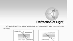
3. BASICS OF OPTICS, – REFLECTION & REFRACTION, Snell’s Law, Snell's law states that the ratio of the sines of the, angles of incidence and refraction is equivalent to, the ratio of phase velocities in the two media, or, equivalent to the reciprocal of, the ratio of the indices of, refraction, , KTUStudents.in, , For more study materials: WWW.KTUSTUDENTS.IN
Page 13 :
3. BASICS OF OPTICS, – REFLECTION & REFRACTION, , KTUStudents.in, , For more study materials: WWW.KTUSTUDENTS.IN
Page 14 :
3. BASICS OF OPTICS, – TOTAL INTERNAL REFLECTION, , KTUStudents.in, , For more study materials: WWW.KTUSTUDENTS.IN
Page 15 :
3. BASICS OF OPTICS, – TOTAL INTERNAL REFLECTION, Total internal reflection is the phenomenon which, occurs when a propagated wave strikes a medium, boundary at an angle larger than a particular critical, angle with respect to the normal to the surface., , KTUStudents.in, , If the refractive index is lower on the other side of, the boundary and the incident angle is greater than, the critical angle, the wave cannot pass through and, is entirely reflected., The critical angle is the angle of incidence above, which the total internal reflection occurs., SinØc = n2/n1, For more study materials: WWW.KTUSTUDENTS.IN
Page 16 :
3. OPTIC FIBER, STRUCTURE, Normally Cylindrical waveguide, Properties – Modes of waveguide, , KTUStudents.in, , Single solid dielectric cylinder (core), radius, a & refractive index n1, , Core is surrounded by cladding, n2 < n1, , Cladding reduce scattering loss & adds mechanical, strength, Normally core is pure silica glass, SiO2, surrounded by, glass, Most fibres are encapsulated with elastic nonabrasive, plastic, For more study materials: WWW.KTUSTUDENTS.IN
Page 17 :
3. TYPES OF OPTIC, FIBER (INDEX), Step Index, If refractive index of core is same throughout, , KTUStudents.in, , Graded Index, , If refractive index of core vary as a function of, radial distance, , For more study materials: WWW.KTUSTUDENTS.IN
Page 18 :
3. TYPES OF OPTIC, FIBER (MODES), Single Mode, 1 mode of propagation, , KTUStudents.in, , Normally LASER is used, Multi Mode, , Multiple modes of propagation, Large core area aids in launching optical power to, the fiber or connecting 2 fibers together. LEDs can, be used, , Disadvantage: Suffer from Intermodal Dispersion, For more study materials: WWW.KTUSTUDENTS.IN
Page 19 :
3. TYPES OF OPTIC, FIBER, , KTUStudents.in, , For more study materials: WWW.KTUSTUDENTS.IN
Page 20 :
3. STEP INDEX FIBER, Core – constant refractive index, n1, Cladding – slightly lower refractive index, s, , KTUStudents.in, , Many Modes can be transmitted through same fiber, – Multimode, Only 1 Mode through same fiber – Single mode, , For more study materials: WWW.KTUSTUDENTS.IN
Page 22 :
4. ADVANTAGES &, DISADVANTAGES, Sl., No, , 1, , Single Mode, Step Index, , Multi Mode, Step Index, , Multi Mode, Graded Index, , KTUStudents.in, Low Intermodal, dispersion, (Broadening of, transmitted light), , Considerable, Dispersion, , Lowest, Dispersion, , 2, , Highest Bandwidth, , Low Bandwidth, , Medium, Bandwidth, , 3, , Coherent sources, are must, , Use of Incoherent, optical sources, (LED can be used, as source), , >, , 4, , Coupling must be, precise, , Easy Coupling, , >, , 5, , For more study materials: WWW.KTUSTUDENTS.IN, , Higher Tolerance, , Lower Tolerance, , >
Page 23 :
COHERENCE, They’re all going, the, same, direction,, and, taking, each, “stroke” in the, same way and at, the same time. In, other words, all, the waves are “in, phase.”, , KTUStudents.in, , For more study materials: WWW.KTUSTUDENTS.IN
Page 24 :
4. NUMBER OF, MODES - SI, , KTUStudents.in, , Here, Ms is the mode volume or total number of, guided modes, , Vc is the cut-off value of normalized frequency, Core Radius a, Relative refractive index difference Δ, , Operating wavelength λ, For more study materials: WWW.KTUSTUDENTS.IN
Page 25 :
4. GRADED INDEX, FIBER, Graded index fibers do not have a constant, refractive index in the core but a decreasing core, index n(r) with radial distance from a maximum, value of n1 at the axis to a constant value n2, , KTUStudents.in, , beyond the core radius a in the cladding, , Δ is the relative refractive index difference, α is the profile parameter, , step index profile when α = ∞, parabolic profile when α = 2, , (BEST), , For more, study materials:, triangular profile, when, α =WWW.KTUSTUDENTS.IN, 1
Page 26 :
4. GRADED INDEX, FIBER, , KTUStudents.in, , For more study materials: WWW.KTUSTUDENTS.IN
Page 27 :
SKEW RAYS, A skew ray is a ray that travels in a non-planar zigzag path and never crosses the axis of an optical, fibre, , KTUStudents.in, , For more study materials: WWW.KTUSTUDENTS.IN
Page 28 :
KTUStudents.in, SIGNAL, DEGRADATION, For more study materials: WWW.KTUSTUDENTS.IN, , Attenuation, Dispersion
Page 29 :
7. ATTENUATION – HWNOTE PREPARATION, In optical fibers, attenuation is the rate at which the, signal light decreases in intensity., , KTUStudents.in, , Glass fiber is used for long-distance fiber optic cables, , Plastic fiber has a higher attenuation and, hence, shorter, range, , Basic attenuation mechanisms, 1. Absorption Loss – Related with material, 2. Scattering Loss – Material and structural imperfections, , 3. Bending Loss – Fiber twisting, , For more study materials: WWW.KTUSTUDENTS.IN
Page 30 :
7. ABSORPTION, , KTUStudents.in, , Atomic defects – Imperfections in atomic structure like, missing molecules, high density clusters of atom groups,, oxygen defects, Direct melt method – Transition metal ions, Water OH, ions, 10 ppb – upto 10dB/km, Intrinsic absorption is associated with fibre base, material, SiO2, Associated with UV & IR bands – Electron –Photon, interaction, For more study materials: WWW.KTUSTUDENTS.IN
Page 31 :
SCATTERING LOSS, Due to microscopic variations in Material Density due to, 1. Compositional fluctuations – Presence of oxides like Sio2,, GeO2, P2O5, This causes Rayleigh Scattering., , KTUStudents.in, , 2. Structural inhomogeneities - Defects in fiber manufacturing, , Trapped air Bubbles, unreacted materials, crystalized regions of, glass, , For more study materials: WWW.KTUSTUDENTS.IN
Page 32 :
7. BENDING LOSS, Radiative losses whenever fiber undergoes a bend, of finite radius of curvature, , KTUStudents.in, , 1. Macroscopic – Large Radii compared with fiber, diameter, , , , Occurs when fiber turns a corner, Macro bending Losses are essentially unobservable till, reaching a critical radius. Once critical radius is reach,, losses occurs exponentially, , 2. Microscopic – Small Radii compared with fiber, diameter, , , , Occurs when fibers are incorporated into cables, Repetitive small scale fluctuations in the radius of, curvature of fiber axis, For more study materials: WWW.KTUSTUDENTS.IN
Page 33 :
6. DISPERSION, Dispersion of light occurs when white light is, separated into its different constituent colours, because of refraction and Snell's law, , KTUStudents.in, , Disadvantages:, , 1. Signal Distortion, , 2. Pulse broadening, 3. Inter Symbol Interference, 4. Low SNR, , For more study materials: WWW.KTUSTUDENTS.IN
Page 34 :
6. TYPES OF, DISPERSION, 1. Group Velocity Dispersion, 2. Modal Dispersion, , KTUStudents.in, , 3. Wave guide Dispersion, , 4. Polarization Mode Dispersion, , For more study materials: WWW.KTUSTUDENTS.IN
Page 35 :
6.1. GROUP VELOCITY, DISPERSION, At the fiber acceptance point, all modes are excited, equally with same energy, , KTUStudents.in, , But as signal propagate, each spectral component, travel independently and undergo time delay or, group delay per unit length, , For more study materials: WWW.KTUSTUDENTS.IN
Page 36 :
6.2 MODAL, DISPERSION, Due to different values of group delay for different, modes, , KTUStudents.in, , Can be eliminated in single mode operation, , Can be minimized by using optimum refractive, index profiles, , For more study materials: WWW.KTUSTUDENTS.IN
Page 37 :
6.3 WAVEGUIDE, DISPERSION, Exists mainly in single mode fibers, We assume that the refractive index is independent, of wavelength, , KTUStudents.in, , For more study materials: WWW.KTUSTUDENTS.IN
Page 38 :
6.4 POLARIZATION, MODE DISPERSION, Type of modal dispersion, 2 different signals of different polarizations may, travel at different velocity through the fiber which, may create dispersion, , KTUStudents.in, , For more study materials: WWW.KTUSTUDENTS.IN
Page 39 :
6.1. MATERIAL, DISPERSION, Happens because refractive index varies as a, function of optical wavelength, , KTUStudents.in, , Figure shows plot of ‘n’ variations in silica, , For more study materials: WWW.KTUSTUDENTS.IN
Page 40 :
POLARIZATION, Light is Transverse, Linear, , KTUStudents.in, , For more study materials: WWW.KTUSTUDENTS.IN
Page 41 :
LINEAR, POLARIZATION, Field of plane linearly polarized waves in k direction, , KTUStudents.in, , Here,, , &, , A0 is Maximum Amplitude of the wave,, , ei is a unit vector parallel to the axis designated by I, Actual measurable electric field is given by real part, of this eqn, , For more study materials: WWW.KTUSTUDENTS.IN
Page 42 :
LINEAR, POLARIZATION, , KTUStudents.in, , For more study materials: WWW.KTUSTUDENTS.IN
Page 43 :
LINEAR, POLARIZATION, , KTUStudents.in, , For more study materials: WWW.KTUSTUDENTS.IN
Page 44 :
KTUStudents.in, MODULE II : FIBER, MATERIALS OPTICAL, SOURCES &, DETECTORS, , For more study materials: WWW.KTUSTUDENTS.IN, , Dr. Vishnu Rajan
Page 45 :
FIBER MATERIALS, 1. Must be possible to make long, thin, flexible fibers, 2. Material must be transparent at a particular optical, wavelength to guide light efficiently, , KTUStudents.in, , 3. Compatible materials that have slightly different, refractive indices for core and cladding must be, available, , Example: Glass & Plastic, Majority of fibers are made using Silica (SiO2) or Silicate, Glass fibers have more efficiency, Plastic fibers are used for short distance transmission in abusive, environments, , For more study materials: WWW.KTUSTUDENTS.IN
 Learn better on this topic