Page 1 :
LECTURE NOTES, For Environmental Health Science Students, , Engineering Drawing, , Wuttet Taffesse,, Laikemariam Kassa, , Haramaya University, In collaboration with the Ethiopia Public Health Training Initiative, The Carter Center,, the Ethiopia Ministry of Health, and the Ethiopia Ministry of Education, , 2005
Page 2 :
Funded under USAID Cooperative Agreement No. 663-A-00-00-0358-00., Produced in collaboration with the Ethiopia Public Health Training Initiative, The Carter, Center, the Ethiopia Ministry of Health, and the Ethiopia Ministry of Education., , Important Guidelines for Printing and Photocopying, Limited permission is granted free of charge to print or photocopy all pages of this, publication for educational, not-for-profit use by health care workers, students or, faculty. All copies must retain all author credits and copyright notices included in the, original document. Under no circumstances is it permissible to sell or distribute on a, commercial basis, or to claim authorship of, copies of material reproduced from this, publication., ©2005 by Wuttet Taffesse, Laikemariam Kassa, All rights reserved. Except as expressly provided above, no part of this publication may, be reproduced or transmitted in any form or by any means, electronic or mechanical,, including photocopying, recording, or by any information storage and retrieval system,, without written permission of the author or authors., , This material is intended for educational use only by practicing health care workers or, students and faculty in a health care field.
Page 3 :
PREFACE, The problem faced today in the learning and teaching of, engineering drawing for Environmental Health Sciences, students in universities, colleges, health institutions, training of, health center emanates primarily from the unavailability of text, books that focus on the needs and scope of Ethiopian, environmental students., This lecture note has been prepared with the primary aim of, alleviating the problems encountered in the teaching of, Engineering Drawing course and in minimizing discrepancies, prevailing among the different teaching and training health, institutions. It can also be used as a reference material for, professional sanitarians., The graphics of engineering design and construction may very, well be the most important course of all studies for an, engineering or technical career. The indisputable reason why, graphics or drawing is so extremely important is that it is the, language, , of the, , designer,, , technician,, , sanitarian,, , and, , engineer, used to communicate designs and construction, details to others. The language of graphics is written in the, form of drawings that represent the shape, size, and, specifications of physical objects. The language is read by, interpreting drawings so that physical objects can be, constructed exactly as originally conceived by the designer., , i
Page 4 :
This lecture note is devoted to provide general aspects of, graphic, , communication, , orthographic, , projections,, , like, maps, , geometric, etc, , construction,, , particularly, , for, , environmental sanitation works such as dry pit latrine, construction, drainage or sewerage construction etc. Each, chapter begins by specifying learning objectives. The text and, the self-explanatory drawings are much helpful to understand, the subject even for the beginners. More over, other, subsidiary topics like sectioning, projection of points and lines, are added to enable students acquire concrete knowledge, and skill for their professional career. Finally, it contains a, glossary, which summarizes important terminologies used in, the text. For further reading, students are encouraged to refer, books which are listed in the bibliography section., , ii
Page 5 :
Acknowledgement, We are delighted to express our thanks to the carter center for, the financial, material and moral support with out which this, material wouldn’t come to reality., We are also glad to extend our heart felt appreciation for Ato, Esayas Alemayehu, Ato Muluken Eyayu, Ato Wossen Tafere, and Ato Dagnew Engidaw for their critical and constructive, comments that are found to be highly essential for this lecture, note preparation., We are very happy to be members of the faculty of health, sciences, Alemaya university for the fact that working with, such faculty are really incomparable., , iii
Page 6 :
TABLE OF CONTENTS, Preface ..............................................................................., , i, , Acknowledgement ................................................................, , iii, , General Objectives..............................................................., , vii, , Chapter 1: Introduction to Graphic Communication ............, 1.1. Drawing .................................................................., 1.1.1 Artistic Drawings .........................................., 1.1.2. Technical Drawings......................................, , 1, 1, 2, 3, , Chapter 2: Drawing Equipments and Their Use .................., 2.1. Introduction ............................................................, 2.2. Important Drawing Equipments, ...................., , 11, 11, 11, , Chapter 3: Lettering and Lines ............................................, 3.1. Letter Styles ..........................................................., , 22, 22, , 3.2. Technique Of Lettering..........................................., , 24, , 3.2.1. .Guide Lines ................................................., , 24, , 3.3. Spacing Of Letters ................................................., , 30, , 3.4. Lettering In Maps ..................................................., , 31, , 3.5. Conventional Lines ................................................, , 31, , Chapter 4: Geometric Construction ....................................., 4.1. 1 Introduction ........................................................., 4.2. Geometric Nomeniclature ......................................, 4.3. Techniques of Geometric Constructions ................, , 35, 35, 36, 42, , Chapter 5: Projection ........................................................., , 66, , 5.1. Introduction ..........................................................., , 67, , 5.1.1. Isometric Drawing ........................................, , 68, , 5.1.2. Orthographic Or Multi View Projection ........., , 70, , 5.2. Theory Of Multi View Projections ..........................., , 72, , 5.2.1. Orthographic Projection ..............................., , 74, , iv
Page 7 :
5.2.2. Classification of Surfaces and Lines in, Orthographic Projections ................................, 5.2.3. Precedence of Lines ...................................., 5.3. Pictorial Projections .............................................., 5.3.1. Isometric Projection ....................................., 5.3.2. Isometric Drawing ........................................, , 82, 89, 90, 94, 96, , Chapter 6: Sectioning .........................................................., 6.1. Sectional Views ...................................................., 6.2. How Sections Are Shown ....................................., 6.3. Multsection Views ................................................, , 101, 101, 106, 109, , Chapter 7: Projection of Points, Lines and Planes .............., 7.1. Introduction .........................................................., 7.2. Reference Planes ................................................., 7.3. Projection of Point ................................................, 7.4. Lines in Space ......................................................, 7.4.1. Classification Of Lines In Orthographic, , 116, 117, 118, 119, 120, , Projections ................................................, , 121, , 7.4.2 Orthographic Projection Of A Line..............., , 124, , 7.4.3. True Size (Shape) Of An Oblique Plane ...., , 146, , Chapter 8: Dimensioning ....................................................., 8.1. Introduction .........................................................., 8.2. Definitions ............................................................, 8.3. Steps in Dimensioning.........................................., 8.4. Where to Put Dimensions....................................., , 149, 149, 150, 152, 153, , Chapter 9: Mapping............................................................., 9.1. Introduction .........................................................., 9.2. Definition ............................................................., 9.3. Purpose ................................................................, 9.4. Classification of Maps .........................................., 9.5. Sketch Map .........................................................., 9.6. Materials Used In a Sketch Mapping For Field or, Office Use ............................................................, 9.7. Procedures for Making a Sketch Map ................., , 159, 159, 160, 161, 162, 166, , v, , 172, 172
Page 8 :
Chapter 10: Building Drawing ............................................., 10.1. Introduction ........................................................, 10.2. Important Terms Used In Building Drawing ......., 10.3. Principles of Architecture...................................., 10.4. Basic Elements of Planning Residential Building, 10.5. Principles of Planning Of Residential Building...., 10.6. Specification Used To Draw the Building Drawing, 10.7. Methods of Making Line and Detailed Drawing .., 10.8. Tips to Draw Building Drawing ..........................., , 176, 176, 177, 180, 182, 175, 189, 191, 194, , Chapter 11. Application of Engineering Drawing In, Environmental Health Projects ......................., Introduction ................................................................., A. Sanitation Projects .................................................., B. Water Projects ........................................................, , 206, 206, 207, 227, , Bibliography ........................................................................., , 231, , vi
Page 9 :
GENERAL OBJECTIVES, This lecture notes will enable the students to:, I., , Explain the concept of graphic communication, their type, and their role in sanitary construction., , II., , Familiarize with different drawing equipment, technical, standards and procedures for construction of geometric, figures., , III., , Equipped with the skill that enables them to convert, pictorial (3-D) drawings to orthographic (2-D) drawings, and vice versa., , IV., , Explain the principle and application of sectioning., , V., , Well familiar with the purpose, procedures, materials and, conventional symbols utilized to make sketch maps., , vii
Page 10 :
CHAPTER ONE, INTRODUCTION TO GRAPHIC, COMMUNICATION, Objectives:, At the end of this chapter students should be able to:, ♦, , Define graphic communication, , ♦, , Mention types of drawing, , ♦, , Explain the difference between different types of, drawings, , ♦, , Mention some of the applications of technical, drawings, , 1.1 Drawing, A drawing is a graphic representation of an object, or a part of, it, and is the result of creative thought by an engineer or, technician. When one person sketches a rough map in giving, direction to another, this is graphic communication. Graphic, communication involves using visual materials to relate ideas., Drawings, photographs, slides, transparencies, and sketches, are all forms of graphic communication. Any medium that, uses a graphic image to aid in conveying a message,, instructions, or an idea is involved in graphic communication., , 1
Page 11 :
One of the most widely used forms of graphic communication, is the drawing., Technically, it can be defined as “a graphic representation of, an idea, a concept or an entity which actually or potentially, exists in life. Drawing is one of the oldest forms of, communicating,, , dating back, , even farther, , than, , verbal, , communication. The drawing itself is a way of communicating, all necessary information about an abstract, such as an idea, or concept or a graphic representation of some real entity,, such as a machine part, house or tools., There are two basic types of drawings: Artistic and Technical, drawings., , 1.1.1 Artistic Drawings, Artistic Drawings range in scope from the simplest line, drawing to the most famous paintings. Regardless of their, complexity, artistic drawings are used to express the feelings,, beliefs, philosophies, and ideas of the artist., In order to understand an artistic drawing, it is sometimes, necessary to first understand the artist. Artists often take a, subtle or abstract approach in communicating through their, drawings, which in turn gives rise to various interpretations., (see figure 1.1), , 2
Page 12 :
Figure 1.1 Artistic drawings, (Source: Goetsch, Technical drawing 3rd ed. USA: Delmar, Publisher Inc., 1994), , 1.1.2 Technical Drawings, The technical drawing, on the other hand, is not subtle, or, abstract. It does not require an understanding of its creator,, only an understanding of technical drawings., A technical drawing is a means of clearly and concisely, communicating all of the information necessary to transform, an idea or a concept in to reality. Therefore, a technical, drawing, , often, , contains, , more, , than, , just, , a, , graphic, , representation of its subject. It also contains dimensions,, notes and specifications. (See figure 1.2), , 3
Page 13 :
Figure 1.2 Technical Drawings, A. Types of Technical Drawings, Technical drawings are based on the fundamental principles, of projections. A projection is a drawing or representation of, an entity on an imaginary plane or planes. This projection, planes serves the same purpose in technical drawing as is, served by the movie screen. A projection involves four, components, 1. The actual object that the drawing or projection, represents, , 4
Page 14 :
2. The eye of the viewer looking at the object, 3. The imaginary projection plane, 4. Imaginary lines of sight called Projectors, The two broad types of projections, both with several subclassifications,, , are, , parallel, , projection, , and, , perspective, , projection., , Parallel Projection, Parallel Projection is a type of projection where the line of, sight or projectors are parallel and are perpendicular to the, picture planes. It is subdivided in to the following three, categories:, , Orthographic,, , Oblique, , and, , Axonometric, , Projections., ♦, , Orthographic projections: are drawn as multi view, drawings, which show flat representations of principal, views of the subject., , ♦, , Oblique Projections: actually show the full size of one, view., , ♦, , Axonometric, , Projections:, , are, , three-dimensional, , drawings, and are of three different varieties:, Isometric, Dimetric and Trimetric., , 5
Page 15 :
Figure 1.3 Orthographic multi view drawing, , Figure 1.4 Oblique drawing, , Figure 1.5 Axonometric drawing, , 6
Page 16 :
Perspective Projection, Perspective projections are drawings which attempt to, replicate what the human eye actually sees when it views an, object. There are three types of perspective projections: Onepoint, Two-point and Three-point Projections., , Figure 1.6 Perspective drawing, , 7
Page 17 :
B. Purpose of Technical Drawings, To appreciate the need for technical drawings, one must, understand the design process. The design process is an, orderly, systematic procedure used in accomplishing a, needed design., Any, , product, , that, , is, , to, , be, , manufactured,, , fabricated,, , assembled, constructed, built, or subjected to any other types, of conversion process must first be designed. For example, a, house must be designed before it can be built., C. Application of Technical Drawing, Technical drawings are used in many different applications., They are needed in any setting, which involves design, and in, any subsequent forms of conversion process. The most, common applications of technical drawings can be found in, the fields of manufacturing, engineering and construction., For instance, Surveyors, civil engineers, sanitarians use, technical drawings to document such works as the layout of a, new subdivisions, or the marking of the boundaries for a piece, of property. Contractors and construction personnel use, technical drawings as their blue prints in converting, architectural and engineering designs in to reality., , 8
Page 18 :
Figure 1.7 Technical drawing (architectural), , 9
Page 19 :
Review questions, 1. Discuss the different types of drawing, 2. Explain the different application of technical drawing, 3. What is graphic communication?, , 10
Page 20 :
CHAPTER TWO, DRAWING EQUIPMENTS AND, THEIR USE, Objectives:, At the end of this chapter students should be able to:, ♦, , List the main drawing equipments, , ♦, , Discuss the use of different drawing equipments, , 2.1 Introduction, To, , record, , information, , on, , paper, , instruments, , and, , equipments are needed. Engineering drawing is entirely a, graphic language hence instruments are essentially, needed. Drawing must be clear, neat and legible in order, to serve its purpose. Hence it is extremely important for, engineers to have good speed, accuracy, legibility and, neatness in the drawing work., , 2.2 Important Drawing Equipments, All drawings are made by means of various instruments. The, quality of drawing depends to a large extent on the quality,, adjustment and care of the instruments., , 11
Page 21 :
i. Drawing Paper, Drawing paper is the paper, on which drawing is to be made., All engineering drawings are made on sheets of paper of, strictly defined sizes, which are set forth in the U.S.S.R, standards. The use of standard size saves paper and ensures, convenient storage of drawings. Now a day, A3 and A4 are, the most commonly used paper sizes. The U.S.S.R standard, establishes five preferred sizes for drawings as tabulated, bellow:, Table 2.1 Description of the size of drawing paper, Size designation, , 11, , 12, , 22, , 24, , 44, , Sheet dimensions, , 297x210, , 297x420, , 594x420, , 594x841, , 1,189x841, , A4, , A3, , A2, , A1, , A0, , in mm, Corresponding, designation, paper, , of, sheets, , according to the, U.S.S.R Standard, (for references), , 12
Page 22 :
A4, , A3, , 297mm, , 297mm, , 420mm, , 210mm, , Figure 2.1 A4 and A3 standard papers, Title block is a rectangular frame that is located at the bottom, of the sheet. It is recommended that space should be, provided in all title blocks for such information as description, of title of the drawing, dates, designer (drawer), and name of, enterprise or educational institute, size (scale), Boarder line, , A3, , A4, Title block, , Boarder line, , 13, , Title block
Page 23 :
Sample for title block, TITLE, DR.BY GUTEMA KETEMA, CHECK.BY, ASSIGN. NO., SCALE, , INSTIT. AU, , DATE 02/02/2003, Figure 2.2 Sample Title block figure, , ii. Triangles (setsquares), They are used to construct the most common angles (i.e. 300,, 450, 600) in technical drawings. The 450 x 450 and 300 x 600, triangles are the most commonly used for ordinary work. They, are shown in the fig. 2.2 below., , 0, , 0, , 45 x45 triangle, , Figure 2.3 triangles or set squares, , 14, , 300x600 triangle
Page 24 :
iii. T- square, It is used primarily to draw horizontal lines and for guiding the, triangles when drawing vertical and inclined lines. It is, manipulated by sliding the working edge (inner face) of the, head along the left edge of the board until the blade is in the, required position., , T-square, Figure 2.4 T-square, , iv. French curve, It is used to draw irregular curves that are not circle arcs. The, shape varies according to the shape of irregular curve., , 15
Page 25 :
Figure 2.5 French curves, , v. Protractor, It is used for laying out and measuring angle., , Figure 2.6 Protractor, , 16
Page 26 :
vi. Scale (ruler), A number of kinds of scales are available for varied types of, engineering design. Figure fig 2.7 Scales with beveled edges, graduated in mm are usually used., , vii. Pencil, The student and professional man should be equipped with a, selection of good, well-sharpened pencil with leads of various, degrees of hardness such as: 9H, 8H, 7H, and 6H (hard); 5H&, 4H (medium hard); 3H and 2H (medium); and H& F (medium, soft). The grade of pencil to be used for various purposes, depends on the type of line desired, the kind of paper, employed, and the humidity, which affects the surface of the, , 17
Page 27 :
paper. Standards for line quality usually will govern the, selection. For instance,, ♦, , 6H is used for light construction line., , ♦, , 4H, , is, , used, , for, , re-penciling, , light, , finished, , lines, , (dimension lines, center lines, and invisible object lines), ♦, , 2H is used for visible object lines, , ♦, , F and H are used for all lettering and freehand work., , Table 2.2. Grade of pencil (lead) and their application, , viii. Compass, It is used to draw circles and arcs both in pencil and ink. It, consists of two legs pivoted at the top. One leg is equipped, with a steel needle attached with a screw, and other shorter, leg is, provided with a socket for detachable inserts., , 18
Page 28 :
viiii. Divider, Used chiefly for transferring distances and occasionally for, dividing spaces into equal parts. i.e. for dividing curved and, straight lines into any number of equal parts, and for, transferring measurements., , Figure 2.8 Compass and divider, , X. Template, A template is a thin, flat piece of plastic containing various, cutout shapes. It is designed to speed the work of the drafter, and to make the finished drawing more accurate. Templates, are available for drawing circles, ellipses, plumbing’s, fixtures, etc. Templates come in many sizes to fit the scale being used, on the drawing. And it should be used wherever possible to, increase accuracy and speed., Drawing board is a board whose top surface is perfectly, smooth and level on which the drawing paper is fastened., , 19
Page 29 :
Clinograph (Adjustable set square)-its two sides are fixed at, 900 and the third side can be adjusted at any angle., Rubber or eraser- extra lines or curves which are not required, in the drawing are to be rubbed out or erased. Hence a rubber, or eraser are required in the drawing work. Erasers are, available in many degrees of hardness, size and shape., Eraser shield –it is an important device to protect lines near, those being erased. It is made up of thin metal plate in which, gaps of different widths and lengths are cut., Tracing paper – it is a thin transparent paper. Figures below it, can be seen easily and traced out in pencil ink., Drawing ink- it is used for making drawings in ink on tracing, paper., , 20
Page 30 :
Review questions, 1. Mention the main drawing equipments, 2. Explain the use of different drawing equipments, 3. Discuss the different type of pencils with their use, , 21
Page 31 :
CHAPTER THREE, LETTERING AND LINES, Objectives:, At the end of this chapter students should be able to:, ♦, , Write letters according to the standard, , ♦, , Explain the different line types, , ♦, , Mention the application of each line type in, technical drawings, , 3.1 Letter Styles, Letter styles are generally classified as Gothic, Roman, Italic, and Text. They were all made with speedball pens, and are, therefore largely single-stroke letters. If the letters are drawn, in outline and filled in, they are referred to as “filled- in” letters., The plainest and most legible style is the gothic from which, our single-stroke engineering letters are derived. The term, roman refers to any letter having wide down ward strokes and, thin connecting strokes. Roman letters include old romans, and modern roman, and may be vertical or inclined. Inclined, letters are also referred to as italic, regardless of the letter, style; text letters are often referred to as old English., , 22
Page 32 :
Figure 3.1 Classification of letter styles, Depending up on the spacing between words and thickness of, strokes, letters may be classified as follows., ♦, , Extended and Condensed Letters, , To meet design or space requirements, letters may be, narrower and spaced closer together, in which case they are, called “Compresed” or “Condensed”letters. If the letters are, wider than normal, they are referred to as “Extended”letters., ♦, , Light Face and Bold Face Letters, , Letters also vary as to the thickness of the stems or strokes., Letters having very thin stems are called Light Face Letters,, while those having heavy stems are called Bold Face Letters., , 23
Page 33 :
3.2 Technique of Lettering, “Any normal person can learn to letter if he is persistent and, intelligent in his efforts.” While it is true that” Practice makes, perfect,” it must be understood that practice alone is not, enough; it must be accompanied by continuous effort to, improve., There are three necessary steps in learning to letter:, 1. Knowledge of the proportions and forms of the letters,, and the order of the strokes., 2. Knowledge of composition- the spacing of the letters, and words., 3. Persistent practice, with continuous effort to improve., , Guide Lines, Extremely light horizontal guidelines are necessary to regulate, the height of letters. In addition, light vertical or inclined, guidelines are needed to keep the letters uniformly vertical or, inclined. Guidelines are absolutely essential for good lettering,, and should be regarded as a welcome aid, not as an, unnecessary requirement., , 24
Page 34 :
Figure 3.2 Guide lines, Make guidelines light, so that they can be erased after the, lettering has been completed. Use a relatively hard pencil, such as a 4H to 6H, with a long, sharp, conical point., , A. Guidelines for Capital Letters, On working drawings, capital letters are commonly made, 3mm high, with the space between lines of lettering from ¾ th, to the full height of the letters. The vertical guidelines are not, used to space the letters (as this should always be done by, eye while lettering), but only to keep the letters uniformly, vertical, and they should accordingly be drawn at random., , Figure 3.3 Guide lines for capital letters, , 25
Page 35 :
A guideline for inclined capital letters is somewhat different., The spacing of horizontal guidelines is the same as for vertical, capital lettering. The American Standard recommends slope, of approximately 68.20 with the horizontal and may be, established by drawing a “sloped triangle”, and drawing the, guidelines at random with T-square and triangles., , Figure 3.4 Guide lines for inclined capital letters, , B. Guidelines for Lower-Case Letters, Lower-case letters have four horizontal guidelines, called the, cap line, waistline, and base line and drop line. Strokes of, letters that extend up to the cap line are called ascenders, and, those that extend down to the drop line, descenders. Since, there are only five letters (p, q.g, j, y) that have descenders,, the drop lines are little needed and are usually omitted. In, spacing guidelines, space “a” may very from 3/5to 2/3 of, space “b”., , 26
Page 36 :
The term single stoke or one stoke does not mean that the, entire letter is made without lifting the pencil. But the width of, the stroke is the width of the stem of the letter., , Single stoke lettering, The salient features of this type of lettering are:, -, , Greatest amount of lettering on drawings is done in a, rapid single stroke letter i.e. either vertical, or inclined., , -, , The ability to letter and perfectly can be acquired only by, continued and careful practice, , -, , it is not a matter of artistic talent or event of dexterity in, hand writing, , Order of strokes, They are necessary to have legible and accurate letter styles., In the following description an alphabet of slightly extended, vertical capitals has-been arranged in-group. Study the slope, of each letter with the order and direction of the storks forming, it. The proportion of height and width of various letters must, be known carefully to letter them perfectly., , The I-H-T Group, -, , The letter I is The Foundation Stroke., , -, , The top of T is drawn first to the full width of the square, and the stem is started accurately at its mid point., , 27
Page 37 :
The L-E-F Group, - The L is made in two strokes., - The first two strokes of the E are the same for the L, the, third or the upper stoke is lightly shorter than the lower, and the last stroke is the third as long as the lower, - F has the same proportion as E, , The V-A-K Group, V is the same width as A, the A bridge is one third up, , -, , from the bottom., The second stroke of K strikes stem one third up from, , -, , the bottom and the third stroke branches from it., , The M-W Group, -, , are the widest letters, , -, , M may be made in consecutive strokes of the two, verticals as of N, , -, , W is made with two V’s, , The O-Q-C-G Group, -, , The O families are made as full circles and made in two, strokes with the left side a longer arc than the right., , -, , A large size C and G can be made more accurately with, an extra stroke at the top., , 28
Page 38 :
The D- U-J Group, -, , The top and bottom stokes of D must be horizontal,, fail line to observe this is a common fault with, beginners, , -, , U is formed by two parallel strokes to which the, bottom stroke be added., , -, , J has the same construction as U, with the first stroke, omitted., , The P-R-B Group, -, , The number of stokes depends up on the size of the, letter., , -, , The middle line of P and R are on centerline of the, vertical line., , Figure 3.5 Order of strokes for capital letters, , 29
Page 39 :
Figure 3.6 Order of strokes for inclined capital letters, , 3.3 Spacing of Letters, Uniformity in spacing of letters is a matter of equalizing, spaces by eye. The background area between letters, not the, distance between them, should be approximately equal. Some, combinations, such as LT and VA, may even have to be, slightly overlapped to secure good spacing. In some cases the, width of a letter may be decreased. For example, the lower, stroke of the L may be shortened when followed by A., , 30
Page 40 :
Words are spaced well apart, but letters with in words, should be spaced closely. Make each word a compact, unit well separated from the adjacent words. For either, upper case or lower-case lettering, make the spaces, between words approximately equal to a capital O. Avoid, spacing letters too far apart and words too close together., , 3.4 Lettering in Maps, Letters are generally used on maps as follows:, ♦, , Vertical capital: name of states, countries, towns,, capitals, titles of the map etc, , ♦, , Vertical lower case: name of small towns, villages, post, offices etc., , ♦, , Inclined capital: name of oceans, bays, gulfs, large, lakes, rivers etc., , ♦, , Inclined lower case: name of rivers, creeks, small, lakes, ponds,, , marshes and springs, , 3.5 Conventional Lines, Each line on a technical drawing has a definite meaning and, is drawn in certain ways. There are certain conventional lines, recommended by American Standard Association. According, to the standard,” three widths of line;, thick, medium, and thin, are recommended… exact thickness may vary according to, the size and type of drawing…”, , 31
Page 41 :
There should also be a distinct contrast in the thickness of, different kinds of lines, particularly between the thick lines and, thin lines., In technical drawings, make construction lines so light that, they can barely be seen, with a hard sharp pencil such as 4H, to 6H. For visible lines, hidden lines, and other “thick” lines, use relatively soft pencils, such as F or H. All thin lines except, construction line must be thin, but dark. They should be made, with a sharp medium grad pencil, such as H or 2H., , 32
Page 42 :
Figure 3.7 Conventional lines, , 33
Page 43 :
Review Questions, 1. Discuss the different types of lines, 2. Explain the application of each line types in technical, drawings, , 34
Page 44 :
CHAPTER FOUR, GEOMETRIC CONSTRUCTION, Objectives:, At the end of this chapter students should be able to:, ♦, , Define geometric nomenclatures like angles, lines etc, , ♦, , Discuss the steps to construct different geometric, figures like lines, arcs, polygon, ellipse etc, , 4.1 Introduction, Strict interpretation of geometric construction allows use of, only the compass and an instrument for drawing straight lines,, and with these, the geometer, following mathematical theory,, accomplishes, , his, , principles, , geometry, , of, , solutions., are, , In, , technical, , employed, , drawing,, , the, , constantly,, , but, , instruments are not limited to the basic two as T-squares,, triangles, scales, curves etc. are used to make constructions, with speed and accuracy. Since there is continual application, of geometric principles, the methods given in this chapter, should be mastered thoroughly. It is assumed that students, using this book understand the elements of plane geometry, and will be able to apply their knowledge., , 35
Page 45 :
The constructions given here afford excellent practice in the, use of instruments. Remember that the results you obtain will, be only as accurate as your skill makes them. Take care in, measuring and drawing so that your drawings will be accurate, and professional in appearance., , 4.2 GEOMETRIC NOMENICLATURE, A. POINTS IN SPACE, A point is an exact location in space or on a drawing surface., A point is actually represented on the drawing by a crisscross, at its exact location. The exact point in space is where the two, lines of the crisscross intersect. When a point is located on an, existing line, a light, short dashed line or cross bar is placed, on the line at the location of the exact point. Never represent a, point on a drawing by a dot; except for sketching locations., B. LINE, Lines are straight elements that have no width, but are infinite, in length (magnitude), and they can be located by two points, which are not on the same spot but fall along the line. Lines, may be straight lines or curved lines.A straight line is the, shortest distance between two points. It can be drawn in any, direction. If a line is indefinite, and the ends are not fixed in, length, the actual length is a matter of convenience. If the end, points of a line are important, they must be marked by means, , 36
Page 46 :
of small, mechanically drawn crossbars, as described by a, pint in space., Straight lines and curved lines are considered parallel if the, shortest distance between them remains constant. The, symbol used for parallel line is //. Lines, which are tangent and, at 900 are considered perpendicular. The symbol for, perpendicular line is ⊥., , Figure 4.1 Points and lines, , C. ANGLE, An angle is formed by the intersection of two lines. There are, three major kinds of angles: right angels, acute angles and, obtuse angles. The right angle is an angle of 900, an acute, angle is an angle less than 900, and an obtuse angle is an, angle more than 900. A straight line is 1800. The symbol for an, angle is < (singular) and <’s (Plural). To draw an angle, use, the drafting machine, a triangle, or a protractor., , 37
Page 47 :
Figure 4.2 Angles, , D. TRIANGLES, A triangle is a closed plane figure with three straight sides and, their interior angles sum up exactly 1800. The various kinds of, triangles: a right triangle, an equilateral triangle, an isosceles, triangle, and an obtuse angled triangle., , Figure 4.3 Triangles, , 38
Page 48 :
E. QUADRIALTERAL, It is a plane figure bounded by four straight sides. When, opposite, , sides, , are, , parallel,, , the, , quadrilateral, , is, , also, , considered to be a parallelogram., , Figure 4.4 Quadrilaterals, , F. POLYGON, A polygon is a closed plane figure with three or more straight, sides. The most important of these polygons as they relate to, drafting are probably the triangle with three sides, square with, four sides, the hexagon with six sides, and the octagon with, eight sides., , Figure 4.5 Polygons, , 39
Page 49 :
G. CIRCLE, A circle is a closed curve with all points on the circle at the, same distance from the center point. The major components, of a circle are the diameter, the radius and circumference., ♦ The diameter of the circle is the straight distance from, one outside curved surface through the center point to, the opposite outside curved surface., ♦ The radius of a circle is the distance from the center, point to the outside curved surface. The radius is half the, diameter, and is used to set the compass when drawing, a diameter., ♦ A central angle: is an angle formed by two radial lines, from the center of the circle., ♦ A sector: is the area of a circle lying between two radial, lines and the circumference., ♦ A quadrant: is a sector with a central angle of 900 and, usually with one of the radial lines oriented horizontally., ♦ A chord: is any straight line whose opposite ends, terminate on the circumference of the circle., ♦ A segment: is the smaller portion of a circle separated by, a chord., ♦ Concentric circles are two or more circles with a common, center point., ♦ Eccentric circles are two or more circles with out a, common center point., , 40
Page 50 :
♦ A semi circle is half of the circle., , Figure 4.6 Circle, , H. SOLIDS, They are geometric figures bounded by plane surfaces. The, surfaces are called faces, and if these are equal regular, polygons, the solids are regular polyhedra, , Figure 4.7 Solids, , 41
Page 51 :
4.3 Techniques of Geometric, constructions, To construct the above mentioned geometric figures, we have, to know some principles and procedures of geometric, construction. Thus, the remaining of this chapter is devoted to, illustrate step-by-step geometric construction procedures used, by drafters and technicians to develop various geometric, forms., A. How to Bisect a Line or an Arc, To bisect a line means to divide it in half or to find its center, point. In the given process, a line will also be constructed at, the exact center point at exactly 900., Given: Line A-B, Step 1: Set the compass approximately two-thirds of the, length of line A-B and swing an arc from point A., Step 2: Using the exact same compass setting, swing an arc, from point B., Step 3: At the two intersections of these arcs, locate points D, and E, Step 4: Draw a straight-line connecting point D with point E., Where this line intersects line A-B, it bisects line A-B., Line D-E is also perpendicular to line A-B at the, exact center point., , 42
Page 52 :
Figure 4.8 Example on how to bisect a line or arc, , B. HOW TO DIVIDE A LINE IN TO Number of EQUAL, PARTS, Given: Line A-B, Step 1: Draw a construction line AC that starts at end A of, given line AB. This new line is longer than the given, line and makes an angle of not more than 300 with it., Step 2: Find a scale that will approximately divide the line AB, in to the number of parts needed (11 in the example, below), and mark these divisions on the line AC., There are now ‘n’ equal divisions from A to D that lie, on the line AC (11 in this example)., Step 3: Set the adjustable triangle to draw a construction line, from point D to point B. Then draw construction lines, through each of the remaining ‘n-1’ divisions parallel, to the first line BD by sliding the triangle along the, , 43
Page 53 :
straight edge. The original line AB will now be, accurately divided., , Figure 4.9 Example on how to divide a line in to a number of, equal parts, , C. How to Bisect an Angle, To bisect an angle means to divide it in half or to cut it in to, two equal angles., Given: Angle BAC, Step 1: Set the compass at any convenient radius and swing, an arc from point A, Step 2: Locate points E and F on the legs of the angle, and, swing two arcs of the, , same identical length from, , points E and F, respectively., , 44
Page 54 :
Step 3: Where these arcs intersect, locate point D. Draw a, straight line from A to, , D. This line will bisect angle, , BAC and establish two equal angles: CAD, , and, , BAD., , Figure 4.10 Example on how to bisect an angle, , D. How to Draw an Arc or Circle (Radius) Through Three, Given Points, Given: Three points in space at random: A, Band C., Step 1: With straight line, lightly connect points A to B, and B, to C,, Step 2: Using the method outlined for bisecting a line, bisect, lines A-B and B-C, Step 3: Locate point X where the two extended bisectors, meet. Point X is the exact center of the arc or circle., Step 4: Place the point of the compass on point X and adjust, the lead to any of the points A, B, or C (they are the, same distance), and swing the circle. If all work is, , 45
Page 55 :
done correctly, the arc or circle should pass through, each point., , Figure 4.11 Example on how to draw an arc or circle, , E. How to Draw a Line Parallel to a Straight Line at a, Given Distance, Given: Line A-B, and a required distance to the parallel line., Step 1: Set the compass at the required distance to the, parallel line. Place the point of the compass at any, location on the given line, and swing a light arc whose, radius is the required distance., Step 2: Adjust the straight edge of either a drafting machine or, an adjusted triangle so that it line sup with line A-B,, slide the straight edge up or down to the extreme high, , 46
Page 56 :
point, which is the tangent point, of the arc, then draw, the parallel line., , Figure 4.12 Example on how to draw parallel line, , F. How to Draw a Line Parallel to a Line Curved Line at a, Given Distance, Given: Curved line A-B, and a required distance to the, parallel line,, Step 1: Set the compass at the required distance to the, parallel line. Starting from either end of the curved, , 47
Page 57 :
line, place the point of the compass on the given line,, and swing a series of light arcs along the given line., Step 2: using an irregular curve, draw a line along the extreme, high points of the arcs., , Figure 4.13 Example on how to draw parallel curved line, , G. How to Draw a Perpendicular Lines to a Line at a Point, Method 1, Given: Line A-B with point P on the same line., Step 1: Using P as a center, make two arcs of equal radius or, more continuous arc (R1) to intercept line A-B on, either side of point P, at points S and T., , 48
Page 58 :
Step 2: Swing larger but equal arcs (R2) from each of points S, and T to cross each other at point U., Step 3: A line from P to U is perpendicular to line A-B at point, P, , Figure 4.14 Example on how to draw a perpendicular line, to a, point outside the line, , 49
Page 59 :
H. How to Draw a Perpendicular to a Line at a Point, Method 2, Given: Line A-B with point P on the line., Step 1: Swing an arc of any convenient radius whose center, O is at any convenient location NOT on line A-B, but, positioned to make the arc cross line A-B at points P, and Q, Step 2: A line from point Q through center O intercepts the, opposite side of the arc at point R, Step 3: Line R-P is perpendicular to line A-B (A right angle, has been inscribed in asemi circle), , Figure 4.15 Example on how to draw a perpendicular line, to a, point on the line, , 50
Page 60 :
I. How to Draw a Perpendicular to a line from a Point Not, on the Line, Given: Line A-B and point P, Step 1: Using P as a center, swing an arc (R1) to intercept, line A-B at points G and H., Step 2: Swing larger, but equal length arcs (R2) from each of, the points G and H to intercept each other at point J., Step 3: Line P-J is perpendicular to line A-B, , Figure 4.16 Example on how to draw a perpendicular line, to a, point outside the line, , 51
Page 61 :
J. How to Draw a Triangle with Known Lengths of Sides, Given: lengths 1, 2, and 3., Step 1: Draw the longest length line, in this example length 3,, with ends A and B. Swing an arc (R1) from point A, whose radius is either length 1 or length 2; in this, example length 1., Step 2; using the radius length not used in step 1, swing an, arc (R2) from point B to intercept the arc swung from, point A at point, Step 3: Connect A to C and B to C to complete the triangle, , Figure 4.17 Example on how to draw triangles with given, sides, , 52
Page 62 :
K. How to Draw a Square, Method-1, Given: The locations of the center and the required distance, across the sides of a square., Step 1: Lightly draw a circle with a diameter equal to the, distance around the sides of the square. Set the, compass at half the required diameter., Step 2: Using triangles, lightly complete the square by, constructing tangent lines to the circle. Allow the light, construction lines to project from the square, with out, erasing them., Step 3: Check to see that there are four equal sides and, if so,, darken in the actual square using the correct line, thickness., , Figure 4.18 Example on how to draw square with given side, , 53
Page 63 :
Method-2, Given one side AB. Through point A, draw a perpendicular., With A as a center, and AB as radius; draw the arc to intersect, the perpendicular at C. With B and C as centers, and AB as, radius, strike arcs to intersect at D. Draw line CD and BD., , Figure 4.19 Example on how to draw square with given side, , L. How to Draw A Pentagon (5 Sides), Given:, , The locations of the pentagon center and the, diameter that will circumscribe the pentagon., , Step 1: Bisect radius OD at C., Step 2: With C as center, and CA as radius, strike arc AE., With A as center, and AE as radius, strike arc EB., Step 3: Draw line AB, then set off distances AB around the, circumference of the circle, and draw the sides, through these points., , 54
Page 64 :
Figure 4.20 Example on how to draw pentagon with a given, side, , M. How to Draw A Hexagon (6 Sides), , Figure 4.21 Example on how to draw hexagon with a given, side, , N. To Draw Any Sided Regular Polygon, To construct a regular polygon with a specific number of, sides, divide the given diameter using the parallel line method, as shown in fig below. In this example, let us assume sevensided regular polygon. Construct an equilateral triangle (0-7-8), with the diameter (0-7) as one of its sides. Draw a line from, , 55
Page 65 :
the apex (point 8) through the second point on the line (point, 2). Extend line 8-2 until it intersects the circle at point 9., Radius 0-9 will be the size of each side of the figure. Using, radius 0-9 step off the corners of the seven sides polygon and, connect the points., , Figure 4.22 Example on how to draw any sided regular, polygon, O. To Draw A Circle Tangent to a Line at a Given Point, Given: Given line AB and a point on the line., Step 1: At P erect a perpendicular to the line., , 56
Page 66 :
Step 2: Set off the radius of the required circle on the, perpendicular., Step 3: Draw circle with radius CP., , Figure 4.23 Example on how to draw a tangent to a line, , P. To Draw a Tangent to A Circle through a Point, Method-1, Given: Point P on the circle., Move the T-square and triangle as a unit until one side of the, triangle passes through the point P and the center of the, circle; then slide the triangle until the other side passes, through point P, and draw the required tangent., Method-2, Given: Point P outside the circle, Move the T-square and triangles as a unit until one side of the, triangle passes through point P and, by inspection, is the, tangent to the circle; and then slide the triangle until the other, side passes through the center of the circle, and lightly mark, , 57
Page 67 :
the point of tangency T. finally move the triangle back to its, starting position and draw the required tangent., , Figure 4.24 Example on how to draw a tangent to a circle, , Q. To Draw Tangents to Two Circles, Move the T-square and triangles as a unit until one side of the, triangle is tangent, by inspection, to the two circles; then slide, the triangle until the other side passes through the center of, one circle, and lightly mark the point of tangency. Then slide, the triangle until the side passes through the center of the, other circle, and mark the point of tangency. Finally slide the, triangle back to the tangent position, and draw the tangent, lines between the two points of tangency. Draw the second, tangent line in similar manner., , 58
Page 68 :
Figure 4.25 Example on how to draw a tangent to two circles, , R. HOW TO CONSTRUCT AN ARC TANGENT TO an Angle, Given: A right angle, lines A and B and a required radius., Step 1: Set the compass at the required radius and, out of the, way, swing a radius from line A and one from line B., Step 2: From the extreme high points of each radius,, construct a light line parallel to line A and another, line parallel to line B., Step 3: Where these lines intersect is the exact location of the, required swing point. Set the compass point on the, swing point and lightly construct the required radius., Allow the radius swing to extend past the required, area. It is important to locate all tangent points (T.P), before darkening in., , 59
Page 69 :
Step 4: Check all work and darken in the radius using the, correct line thickness. Darken in connecting straight, lines as required. Always construct compass work, first, followed by straight lines. Leave all light, construction lines., , Figure 4.26 Example on how to draw an arc tangent to an, angle, , 60
Page 70 :
S. How to Construct an Arc Tangent to Two Radii or, Diameters, Given: Diameter A and arc B with center points located, and, the required radius., Step 1: Set the compass at the required radius and, out of the, way, swing a radius of the required length from a, point on the circumference of given diameter A. Out of, the way, swing a required radius from a point on the, circumference of a given arc B., Step 2: From the extreme high points of each radius,, construct a light radius out side of the given radii A, and B., Step 3: Where these arcs intersect is the exact location of the, required swing point. Set the compass point on the, swing point and lightly construct the required radius., Allow the radius swing to extend past the required, area., Step 4: Check all work; darken in the radii using the correct, line thickness. Darken in the arcs or radii in, consecutive order from left to right or from right to left,, thus constructing a smooth connecting line having no, apparent change in direction., , 61
Page 71 :
Figure 4.27 Example on how to draw an arc tangent to two, radii or diameter, , T. To Draw an Ellipse (By Four-Centered Method), Join 1 and 3, layoff 3-5 equal to 01-03. This is done, graphically as indicated in the fig. Below by swinging 1 around, to 5 with O as center where now 03 from 05 is 3-5; the, required distance. With 3 as center, an arc from 5 to the, diagonal 1-3 locates 6. Bisect 1-6 by a perpendicular crossing, 0-1 at 9 and intersecting 0-4 produced (if necessary) at 10., , 62
Page 72 :
Make 0-9’ equal to 0-9, and 0-10’ equal to 0-10. Then 9, 9’,, 10, and 10’ will be centers for four tangent circle arcs forming, a curve approximating the shape of an ellipse., , Figure 4.28 Example on ellipse construction using four, centered method, , U. How to Draw an Ogee Curve, An ogee curve is used to join two parallel lines. It forms a, gentle curve that reverses itself in a neat symmetrical, geometric form., Given: Parallel lines A-B and C-D, Step 1: Draw a straight line connecting the space between the, parallel lines. In this example, from point B to point C., Step 2: Make a perpendicular bisector to line B-C to establish, point X., , 63
Page 73 :
Step 3: Draw a perpendicular from line A-B at point B to, intersect the perpendicular bisector of B-X, which, locates the first required swing center. Draw a, perpendicular from line C-D at point C to intersect the, perpendicular bisector of CX, which locates the, second required swing center., Step 4: Place the compass point and adjust the compass lead, to point B, and swing an arc from B to X. Place the, compass point on the second swing point and swing, an arc from X to C. This completes the ogee curve., , Figure 4.29 Example on ogee curve construction, , 64
Page 74 :
Review questions, 1. The side of a certain triangle is 2 cm. Construct an, equilateral triangle based on the given side by using, compass and ruler., 2. Show the procedure how to divide a line in to number of, equal parts, 3. Draw a line parallel to straight line AB at 2cm distance., , 65
Page 75 :
CHAPTER FIVE, PROJECTION, Objective:, At the end of this chapter, the students should be able to:, ♦, , Explain the purpose and theory of multi view projections, , ♦, , Describe “Glass Box Method” of orthographic projection, , ♦, , Mention the principal views and combination of views, , ♦, , Convert pictorial drawings in to orthographic or multi, view projection, , ♦, , Describe representation of circular surfaces, hidden, surfaces in orthographic projection, , ♦, , List the precedence of lines in multi view projection, , ♦, , Explain the necessity of pictorial projection, , ♦, , Discuss the procedure to construct box for isometric, and oblique drawings, , ♦, , Convert, , orthographic, , projection, , projection, , 66, , in, , to, , isometric
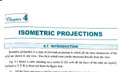
Page 76 :
5.1 Introduction, All forms of engineering and technical work require that a twodimensional surface (paper) be used to communicate ideas, and the physical description of a variety of shapes. Here, projections have been divided in to two basic categories;, pictorial and multi view. This simple division separates single, view projections (oblique, perspective and isometric) from, multi, , view, , projections, , (orthographic)., , Theoretically,, , projections can be classified as convergent and parallel, or, divided in to three systems of projection: perspective, oblique,, and orthographic. Division of types based on whether the, drawing is a one view or multi view projection sufficiently, separate projection types in to those used for engineering, working drawings (orthographic) and those used for display, (architectural rendering, technical illustrations etc), In short, one of the best ways to communicate one's ideas is, through some form of picture or drawing. This is especially, true for the engineer. The purpose of this chapter is to give, you the basics of engineering sketching and drawing., We will treat "sketching" and "drawing" as one. "Sketching", generally, means freehand drawing. "Drawing" usually, means, using drawing instruments, from compasses to computers to, bring precision to the drawings., , 67
Page 77 :
Before we get started on any technical drawings, let's get a, good look at this strange block (figure 5.1) from several, angles., , Figure 5.1 Machine block, , 5.1.1 Isometric Drawing, The representation of the object in figure 5.2 is called an, isometric drawing. This is one of a family of three-dimensional, views called pictorial drawings. In an isometric drawing, the, object's vertical lines are drawn vertically, and the horizontal, lines in the width and depth planes are shown at 30 degrees, to the horizontal. When drawn under these guidelines, the, lines parallel to these three axes are at their true (scale), lengths. Lines that are not parallel to these axes will not be of, their true length., , 68
Page 78 :
Figure 5.2 Isometric drawing, Any engineering drawing should show everything: a complete, understanding of the object should be possible from the, drawing. If the isometric drawing can show all details and all, dimensions on one drawing, it is ideal., One can pack a great deal of information into an isometric, drawing. Look, for instance, at the instructions for a home, woodworker in figure 5.2. Everything the designer needs to, convey to the craftsperson is in this one isometric drawing., However, if the object in figure 5.2 had a hole on the back, side, it would not be visible using a single isometric drawing., In order to get a more complete view of the object, an, orthographic projection may be used., , 69
Page 79 :
5.1.2 Orthographic or Multi view Projection, Imagine that you have an object suspended by transparent, threads inside a glass box, as in figure 5.3., , Figure 5.3 Orthographic projection, Then draw the object on each of three faces as seen from that, direction. Unfold the box (figure 5.4) and you have the three, views. We call this an "orthographic" or "multi view" drawing., , 70
Page 80 :
Figure 5.4 the creation of an orthographic multi view drawing, Figure 5.5 shows how the three views appear on a piece of, paper after unfolding the box., , Figure 5.5 a multi view drawing and its explanation, , 71
Page 81 :
Which views should one choose for a multi view drawing? The, views that reveal every detail about the object. Three views, are not always necessary; we need only as many views as, are required to describe the object fully. For example, some, objects need only two views, while others need four. The, circular object in figure 5.6 requires only two views., , Figure 5.6 an object needing only two orthogonal views, , 5.2 Theory of Multi view Projections, Multi view orthographic projection is the primary means of, graphic communication used in engineering work. Drawings, are used to convey ideas, dimensions, shapes, and, procedures for the manufacture of the object or construction, of a system. Orthographic projection is the basis of all, descriptive geometry procedures. Multi view projection is a, procedure that can be used to completely describe an object’s, shape and dimensions using two or more views that are, normally projected at 900 to each other, or at specified angles., In general, engineering work is complete using this method of, , 72
Page 82 :
projection. The finished drawing is then reproduced and sent, to the shop or to the job site., To design and communication every detail to manufacturing, groups, , (Engineers,, , technicians), , descriptions, , must, , be, , prepared. This description must show every aspect of the, shape and size of each part and of the complete structure., Because of this necessity graphics is the fundamental method, of communication only as a supplement, for notes and, specifications, is the word language used., Shape is described by projection that is by the process of, causing an image to be formed by rays of sight taken in a, particular direction from an object to a picture plane. Methods, of projection vary according to the direction in which the rays, of sight are taken to the plane. When the rays are, perpendicular to the plane, the projective method is, Orthographic. If the rays are at an angle to the plane, the, projective method is called oblique. Rays taken to a particular, station point result in perspective projection. By the methods, of perspective, the object is represented as it would appear to, the eye., Theory of projection is the basis of background information, necessary, , to, , shape, , representation, , in, , graphics., , Two, , fundamental methods of shape representation are used., 1. Orthographic view consists of a set of two or more, separate views of an object taken from different, , 73
Page 83 :
directions, generally at right angles to each other and, arranged relative to each other in a definite way. Each of, the views shows the shape of the object for a particular, view direction and collectively the views describe the, object completely., 2. Pictorial view, in which the object is oriented behind and, projected up on a single plane. Either oblique on, perspective projection is used., , 5.2.1 Orthographic Projection, A. Definition, Basically, Orthographic projection could be defined as any, single projection made by dropping perpendiculars to a plane., In short, orthographic projection is the method of representing, the exact shape of an object by dropping perpendiculars from, two or more sides of the object to planes, generally at right, angles to each other; collectively, the views on these planes, describe the object completely., Descriptive geometry is basically the use of orthographic, projection in order to solve for advanced technical data, involving the spatial relation ship of points, lines, planes, and, solid shapes. The most common means of understanding, these types of orthographic projection is The Glass Box, method., , 74
Page 84 :
The Glass Box method, used primarily for descriptive, geometry problems, requires that the user imagine that the, object, points, lines, planes etc are enclosed in a transparent, “box”. Each view of the object is established on its, corresponding glass box surface by means of perpendicular, projectors originating at each point of the object and extending, to the related box surface. The box is hinged so that it can be, unfolded on to one flat plane (the paper)., The lines of sight representing the direction from which the, object is viewed. In figure 5.7, the vertical lines of sight (A), and horizontal lines of sight (B) are assumed to originate at, infinity. The line of sight is always perpendicular to the image, plane, represented by the surfaces of the glass box (top, front,, and right side). Projection lines(c) connect the same point on, the image plane from view to view, always at right angle., A point is projected up on the image plane where its projector,, or line of sight, pierces that image plane. In the figure 5.8,, point 1, which represents a corner of the given object, has, been projected on to the three primary image planes. Where it, is intersects the horizontal plane (top image plane), it is, identified as 1H, when it intersects the frontal plane (front, image plane), it is identified as 1F, and where it intersects the, profile plane (right side image plane), it is labeled 1P., , 75
Page 85 :
Figure 5.7 Glass box methods, , 76
Page 86 :
Figure 5.8 Orthographic projection of objects, B. Orthographic views, It is the picture or view or thought of as being found by, extending perpendiculars to the plane from all points of the, object. This picture, or projection on a frontal plane, shows the, shape of the object when viewed from the front but it does not, tell the shape or distance from front to real. Accordingly, more, than one protection is required to describe the object., , 77
Page 87 :
If transparent plane is placed horizontally above the object,, the projection on this plane found by extending perpendiculars, to it from the object, will give the appearance of the object as, if viewed from directly above and will show the distance from, frontal plane. Then the horizontal plane is now rotated into, coincidence with the frontal plane. Now again a third plane,, perpendicular to the first two called profile plane are used to, view an object from the side., C. The Six Principal Views, Let us surround the object entirely by asset of six planes,, each at fight angles to each other. On these planes, views of, the object can be obtained as is seen from the top, front, and, right side, left side, bottom and rear., Think now of the six sides, or the plane of the paper. The front, is already in the plane of the paper, and the other sides are,, as it were, hinged and rotated in position as shown. The, projection on the frontal plane is the front view vertical, projection, or front elevation, that on the horizontal plane, the, top view, horizontal projection, or plan, that on the side, profile, view, side view, profile projection, or side elevation. By, reversing the direction of sight, a bottom view is obtained, instead of a top view, or a rear view instead of a front view., , 78
Page 88 :
Figure 5.9 Principal Picture Planes, , 79
Page 89 :
In actual work, there is rarely an occasion when all six, principal views are needed on one drawing. All these views, are principal views. Each of the six views shows two of the, three dimensions of height, width and depth., In general, when the glass box is opened, its six sides are, revolved outward so that they lie in the plane of the paper., And each image plane is perpendicular to its adjacent image, plane and parallel to the image plane across from it. Before it, is revolved around its hinged fold line (reference line). A fold, line is the line of intersection between any hinged (adjacent), image planes., The left side, front, right side, and back are all elevation views., Each is vertical. The top and bottom planes are in the, horizontal plane. But in most cases the top, front, and right, sides are required., D. COMBINATION OF VIEWS, The most usual combination selected from the six possible, views consists of the top, front, and right side views some, times the left- side view helps to describe an object more, clearly then the light side view., N.B: The side view of the front face of the object is adjacent to, the front view and the side view of a point will be at the, same distance from the front surface as its distance from, the front surface on the top view., , 80
Page 90 :
The six principal views of an object or the glass box have, previously been presented in the type of orthographic, projection known as Third Angle Orthographic Projection. This, form of projection is used throughout this lecture note and is, primary form of projection found in all American Industry with, the exception of some special cases in the architectural and, structural fields., , Figure 5.10 Third angle projections, The type of projection used in most foreign countries and on, many American Structural and architectural drawings is called, First Angle Orthographic Projections., In this form of projection, the object is assumed to be in front, of the image plane. Each view is formed by projecting through, the object and on to the image plane., , 81
Page 91 :
Figure 5.11 First angle projections, , 5.2.2 Classification of surfaces and Lines in, Orthographic Projections, Any object, depending upon its shape and space position may, or may not have some surfaces parallel or perpendicular to, the planes of projection., Surfaces are classified according to their space relation ship, with the planes of projection i.e. horizontal, frontal and profile, surfaces. When a surface is inclined to two of the planes of, projection (but perpendicular to the third, the surface is said to, be auxiliary or inclined .It the surface is at angle to all three, planes, the term oblique or skew is used, Although uniform in appearance, the lines on a drawing may, indicate three different types of directional change on the, object. An edge view is a line showing the edge of a, projection. An intersection is a line formed by the meeting of, two surfaces where either one surface is parallel and one at, an angle or both are at an angle to the plane of projection. A, , 82
Page 92 :
surface limit is a line that indicates the reversal of direction of, a curved surface., A. Horizontal, Frontal and Profile Surfaces, The edges (represented by lines) bounding a surface may be, in a simple position or inclined to the planes of projection, depending up on the shape or position, the surface takes is, name from the plane of projection. Thus, a horizontal line is a, line in a horizontal plane; a frontal line is a line in a frontal, plane; and a profile line is a line in a profile plane. When a line, is parallel to two planes, the line takes the name of both, planes as horizontal frontal, horizontal- profile, or frontal –, profile., , Figure 5.12 Examples of objects having parallel surfaces to, the principal planes, , 83
Page 93 :
B. Inclined Surfaces, An edge appears in true length when it is parallel to the plane, of projection, as a point when it is perpendicular to the plane, and shorter than true length when it is inclined to the plane., Similarly, a surface appears in trey shape when it is parallel to, the planes of projection, as alien when it is perpendicular to, the plane, and fore shortened when it inclined to the plane. An, object with its face parallel to the plans of projection as figure, 5.12; a top, front, and right side surfaces are shown in true, shape and the object edges appear either in true length or as, points. The inclined surface of the object as figure 5.13 does, not show true shape in any of the views but appears as an, edge in front view. The front and rear edges of the inclined, surface are in true length in the front view and fore shortened, in the top and side views. The top and bottom edges of the, inclined surface appear in true length in top and side views, and as points in the front view., , 84
Page 94 :
Figure 5.13 Examples of objects having inclined surfaces, , C. Oblique Surfaces, A line that is not parallel to any plane of projection is called an, oblique skew line and it does not show in true shape in any of, the views, but each of the bounding edges shows interval, length in one view and is fore shortened in the other two, views,, , 85
Page 95 :
Figure 5.14 Examples of objects having oblique surfaces, D. Hidden Surfaces, To describe an object with complex internal features, completely, a drawing should contain lines representing all the, edges, intersections, and surface limits of the objects In any, view there will be some parts of the object that can not be, seen from the position of the observer, as they will be covered, by station of the object closer to the observer’s eye. The, edges, intersections, and surface limits of these hidden parts, are indicated by a discontinuous line called a dashed line. In, , 86
Page 96 :
figure 5.15, the drilled hole that is visible in the top-side view, is hidden in the front and right side views, and there fore it is, indicated in these views by a dashed line showing the hole, and the shape as left by the drill., , Figure 5.15 Examples of objects having hidden surfaces, Particular attention should be paid to the execution of these, dashed lines. It carelessly drawn, they ruin the appearance of, a drawing. Dashed lines are drawn lighten full lines, of short, dashes uniform in length with the space between there very, short, about ¼ of the length of the dash., This view shows the shape of the object when viewed from, the side and the distance from bottom to top and front to rear., The horizontal and profile planes are rotated in to the same, plane as the frontal plane. Thus, related in the same plane,, they give correctly the three dimensional shape of the object., , 87
Page 97 :
E. Curved Surfaces, To represent curved surfaces in orthographic projections,, center lines are commonly utilized. All the center lines, which, are the axes of symmetry, for all symmetrical views are a part, of views., 1. Every part with an axis, such as a cylinder will have the, axis drawn as center line before the part is drawn., 2. Every circle will have its center at the intersection of two, mutually perpendicular center lines., , 88
Page 98 :
The standard symbol for center lines on finished drawings is a, fine line made up of alternate long and short dashes., , Figure 5.16 Examples of objects having curved surfaces, , 5.2.3 Precedence of lines, In any view there is likely to be a coincidence of lines. Hidden, portions of the object may project to coincide with visible, portions Center lines may occur where there is a visible or, hidden out line of some part of the object., Since the physical features of the object must be represented, full and dashed lines take precedence over all other lines, since visible out line is more prominent by space position, full, lines take precedence over dashed lines. A full line could, cover a dashed line, but a dashed line could not cover a full, line. It is evident that a dashed line could not occur as one of, the boundary lines of a view., , 89
Page 99 :
When a centerline and cutting- plane line coincide, the one, that is more important to the readability of the drawing takes, precedent over the other., Break lines should be placed so as not to coincide with other, lines of the drawing., The following line gives the order of precedence of lines., 1. Full line, 2. Dashed line, 3. Careful line or cutting – plane line, 4. Break lines, 5. Dimension and extension lines., 6. Crosshatch lines., , 5.3 Pictorial Projections, By means of multi view drawing, it is possible to represent, accurately the most complex forms by showing a series of, exterior views and sections. This type of representation has,, however, two limitations: its execution requires a through, understanding of the principles of multi view projection, and, it’s reading requires a definite exercise of the constructive, imagination., Frequently it is necessary to prepare drawings that are, accurate and scientifically correct, and that can be easily, understood by persons with out technical training. Such, drawings show several faces of an object at once,, , 90
Page 100 :
approximately as they appear to the observer. This type of, drawing is called pictorial drawing. Since pictorial drawing, shows only the appearances of objects, it is not satisfactory, for completely describing complex or detailed forms., As we have seen in the previous chapters, the four principal, types of projection are:, ♦ Multi view projection, ♦ Axonometric projection, ♦ Oblique projection, ♦ Perspective projection, All except the regular multi view projection are pictorial types, since they show several sides of the object in a single view. In, all cases the view or projections are formed by the piercing, points in the plane of projection of an infinite number of visual, rays or projectors. In this chapter, we will focus on the, common types of pictorial projection i.e. isometric projection., , 91
Page 101 :
Figure 5.17 types of projection, In both multi view projection and axonometric projection, the, observer is considered to be at infinity, and the visual rays are, perpendicular to the plane of projection. There fore, both are, classified as Orthographic Projections., In Oblique projection, the observer is considered to be at, infinity, and the visual rays are parallel to each other but, oblique to the plane of projection., In Perspective, the observer is considered to be at a finite, distance from the object, and the visual rays extend from the, observer’s eye, or the station point (SP), to all points of the, object to form a so-called “cone of rays.”, , 92
Page 102 :
The distinguishing feature of axonometric projection, as, compared to multi view projection, is the inclined position of, the object with respect to the plane of projection. Since the, principal edges and surfaces of the object are inclined to the, plane of projection, the lengths of the lines, the sizes of the, angle, and the general proportions of the object vary with the, infinite number of possible positions in which the object may, be placed with respect to the plane of projection. Three of, these are shown below., In these cases the edges of the cube are inclined to the plane, of projection, and therefore foreshortened. The degree of, foreshortening of any line depends on its angle with the plane, of projection; the greater the angle the greater the, foreshortening. If the degree of the foreshortening is, determined for each of the three edges of the cube which, meet at one corner, scales can be easily constructed for, measuring along these edges or any other edges parallel to, them. It is customary to consider the three edges of the cube, which meet at the corner nearest to the observer as the, axonometric axes., Axonometric projections are classified as, a) Isometric projection, b) Dimetric Projection, c) Trimetric Projection, depending up on the number of, scales of reduction required., , 93
Page 103 :
Figure 5.18 Axonometric projections, Since the most widely used method of axonometric projection, is Isometric, we will only see isometric projection in detail., , 5.3.1 Isometric Projection, To produce an isometric projection (Isometric means “equal, measure”), it is necessary to place the object so that its, principal edges or axes, make equal angles with the plane of, projection, and are therefore foreshortened equally. In this, position the edges of a cube would be projected equally and, would make equal angles with each other (1200)., , 94
Page 104 :
Figure 5.19 Isometric Projection, In the figure above, the projections of the axes OX, OY and, OZ make angles of 1200 with each other, and are called the, isometric axes. Any line parallel to one of these is called an, Isometric line; a line which is not parallel is called a nonisometric line. It should be noted that the angles in the, isometric projection of the cube are either 1200 or 600 and that, all projections of 900 angles. In an isometric projection of a, cube, the faces of the cube or any planes parallel to them are, called Isometric planes., , 95
Page 105 :
5.3.2 Isometric Drawing, When a drawing is prepared with an isometric scale or other, wise as the object is actually projected on a plane of, projection, it is an isometric projection. But when it is prepared, with an ordinary scale, it is an isometric drawing. The, isometric drawing is 22.5% larger than the isometric, projection, but the pictorial value is obviously the same in, both., Since the isometric projection is foreshortened and an, isometric drawing is full size, it is customary to make an, isometric drawing rather than an isometric projection, because, it is so much easier to execute and, for all practical purposes,, is just as satisfactory as the isometric projection., The steps in constructing an isometric drawing of an object, composed only of normal surfaces, as illustrated in figure 5.20, .Notice that all measurements are made parallel to the main, edges of enclosing box, that is, parallel to isometric axes. No, measurement along a diagonal (non-isometric line) on any, surface or through the object can be set off directly with the, scale. The object may be drawn in the same position by, beginning at the corner Y or any other corner, instead of at the, corner X., , 96
Page 106 :
The method of constructing an isometric drawing of an object, composed partly of inclined surface (and oblique edges) is, shown in figure 5.20 .Notice that inclined surfaces are, located by offset measurements along isometric lines., , Figure 5.20 Isometric drawing of normal surfaces, For example, dimensions E and F are setoff to locate the, inclined surface M, and dimensions A and B are used to, locate surface N., , 97
Page 107 :
Box Construction, Objects of rectangular shape may be more easily drawn by, means of box construction, which consists simply in imagining, the object to be enclosed in a rectangular box whose sides, coincide with the main faces of the object. For example, in fig, below, the object shown in two views is imagined to be, enclosed in a construction box., This box is then drawn lightly with construction lines, I, the, irregular features are then constructed, II, and finally, III, the, required lines are made heavy., , Figure 5.21 isometric box constructions, , 98
Page 108 :
Lines in Isometric Drawing, ♦, , Hidden Lines, , The use of hidden lines in isometric drawing is governed by, the same rules as in all other types of projection: Hidden lines, are omitted unless they are needed to make the drawing, clear. If a projecting part cannot be clearly shown with out the, use of hidden lines, then hidden lines are needed., ♦, , Center Lines, , The use of center lines in isometric drawing is governed by, the same rules as in multi view drawing: center lines are, drawn if they are needed to indicate symmetry, or if they are, needed for dimensioning. In general, center lines should be, used sparingly, and omitted in cases of doubt. The use of too, many center lines may produce a confusion of lines, which, diminishes the clearness of the drawing., , 99
Page 109 :
Review question, 1. Explain the purpose and theory of multi view projections, 2. Construct a box for isometric and oblique drawings based, on the technical drawing procedure., 3. Describe “Glass box method“ of orthographic projections., , 100
Page 110 :
CHAPTER SIX, SECTIONING, Objectives:, At the end of this chapter, the students should be able to:, ♦, , Describe the purpose of sectioning in technical, drawings, , ♦, , Define cutting plane lines, direction of sight, section, lining etc, , ♦, , Mention and explain the different kinds of sectioning, , 6.1 SECTIONAL VIEWS, Sectioning, It is defined as an imaginary cut made through an object to, expose the interior or to reveal the shape of a portion., Sectional view, It is a view in which all or a substantial portion of the view is, sectioned. There are many times when the interior details of, an object cannot be seen from the outside (figure 6.1)., , 101
Page 111 :
Figure 6.1 An isometric drawing that does not show all details, We can get around this by pretending to cut the object on a, plane and showing the "sectional view". The sectional view is, applicable to objects like engine blocks, where the interior, details are intricate and would be very difficult to understand, through the use of "hidden" lines (hidden lines are, by, convention, dotted) on an orthographic or isometric drawing., Imagine slicing the object in the middle (figure 6.2), , Figure 6.2 Sectioning an object, , 102
Page 112 :
Figure 6.3 sectioning the object in figure 6.1, Take away the front half (figure 6.3) and what you have is a, full section view (figure 6.4)., , Figure 6.4 Sectioned isometric and orthogonal views, The cross-section looks like figure 6.4 when it is viewed from, straight ahead., , 103
Page 113 :
In short, when the interior of the object is complicated or when, the component parts of a machine are drawn assembled, an, attempt to show hidden portions by the customary dashed, lines in regular or graphic views often results in a confusing, networks, which is difficult to draw and almost impossible to, read clearly., In case of this kind, to aid in describing the object, one or, more views are drawn to show the object as if a portion has, been cut away to show the interior., For some simple objects where the orthographic un sectioned, views can be easily read, sectional views are often preferable, because they show clearly and emphasis the solid portions,, the voids, and the shape., Cross-Sectional Views, A cross-sectional view portrays a cut-away portion of the, object and is another way to show hidden components in a, device., Imagine a plane that cuts vertically through the center of the, pillow block as shown in figure 6.5 (a) and (b). Then imagine, removing the material from the front of this plane, as shown in, figure 6.5 (b)., , 104
Page 114 :
Figure 6.5 Section of an object with circular holes, This is how the remaining rear section would look. Diagonal, lines (cross-hatches) show regions where materials have, been cut by the cutting plane., , Figure 6.6 Section A-A, This cross-sectional view (section A-A, figure 6.6), one that is, orthogonal to the viewing direction, shows the relationships of, lengths and diameters better. These drawings are easier to, , 105
Page 115 :
make than isometric drawings. Seasoned engineers can, interpret orthogonal drawings without needing an isometric, drawing, but this takes a bit of practice., The top "outside" view of the bearing is shown in figure 6.7. It, is an orthogonal (perpendicular) projection. Notice the, direction of the arrows for the "A-A" cutting plane., , Figure 6.7 The top “out side” view of the bearing, , 6.2 HOW SECTIONS ARE SHOWN, To clearly draw the sectional views, we have to understand, the following terminologies., A. Cutting Plane Lines, The cutting plane line indicates the path that an imaginary, cutting plane follows to slice through an object. Think of the, , 106
Page 116 :
cutting plane line as a saw blade that is used to cut through, the object. The cutting-plane line is represented by a thick, black dashed line., , Figure 6.8 cutting plane lines, B .Direction of Sight, The drafter must indicate the direction in which the object is to, be viewed after it is sliced or cut through. This is, accomplished by adding a short leader and arrowhead to the, ends of the cutting-plane. And these arrows indicate the, direction of sight., , 107
Page 117 :
Figure 6.9 The direction of sight, , C. Section Lining, Section lining shows where the object is sliced or cut by the, cutting plane line. Section lining is represented by thin, black, lines drawn at 450 to the horizontal. Section lining is spaced, by eye from 1.5mm to 6mm apart, depending up on the, overall size of the object. The average spacing used for most, drawings is 3mm. Section lines must be of uniform thickness, (thin black) and evenly spaced by eye., If the cutting plane passes through more than two parts,, section lining of each individual part must be drawn at, different angles. Where an angle other than 450 is used, the, angle should be 300 or 600. Section lining should not be, parallel with the sides of the object to be section lined., , 108
Page 118 :
Figure 6.10 Section lining, , 6.3 MULTSECTION VIEWS, The different kinds of sections used today are:, ♦, , Full section, , ♦, , Offset section, , ♦, , Half section, , ♦, , Broken-out section, , ♦, , Revolved section, , ♦, , Auxillary section etc., , In this part, we only consider the most commonly used types, of sections., , 109
Page 119 :
Full Section, It is simply a section of one of the regular multi-views that, sliced or cut completely in two., , Figure 6.11 Full Section, , 110
Page 120 :
Offset Section, Many times, important features do not fall in a straight line as, they do in a full section. These important features can be, illustrated in an offset section by bending or offsetting the, cutting-plane line. An offset section is very similar to a full, section, except that the cutting plane line is not straight., , Figure 6.12 Offset sections, , 111
Page 121 :
Half-Sections, A half-section is a view of an object showing one-half of the, view in section, as in figure 6.13 (a) and (b), , (a), , (b), Figure 6.13 (a) Full and sectioned isometric views (b) Front, view and half section, , 112
Page 122 :
The diagonal lines on the section drawing are used to indicate, the area that has been theoretically cut. These lines are called, section lining or cross-hatching. The lines are thin and are, usually drawn at a 45-degree angle to the major outline of the, object. The spacing between lines should be uniform., A second, rarer, use of cross-hatching is to indicate the, material of the object. One form of cross-hatching may be, used for cast iron, another for bronze, and so forth. More, usually, the type of material is indicated elsewhere on the, drawing, making the use of different types of cross-hatching, unnecessary., , Figure 6.14 Half section without hidden lines, , 113
Page 123 :
Usually hidden (dotted) lines are not used on the crosssection unless they are needed for dimensioning purposes., Also, some hidden lines on the non-sectioned part of the, drawings are not needed (figure 6.13) since they become, redundant information and may clutter the drawing., , 114
Page 124 :
Review questions, 1. Describe the purpose of sectioning in technical drawings, 2. What is “direction of sight” in sectioning?, 3. Mention the difference between offset section and full, section., , 115
Page 125 :
CHAPTER SEVEN, PROJECTION OF POINTS, LINES, AND PLANES, Objectives:, At the end of the chapter, students should be able to:, ♦, , Discuss reference line, picture planes and views, , ♦, , Classify lines based on direction, type etc., , ♦, , Explain, , the orthographic projection of points and, , lines ( principal, vertical and inclined lines etc), ♦, , Draw the true length of an oblique lines, , ♦, , Explain how to draw a point view of a line, , ♦, , Define principal planes, , ♦, , List out the main difference between types of principal, planes, , ♦, , Explain the use of edge view and steps to draw an, edge view of a plane, , ♦, , Discuss the procedures how to draw true shape/size, of oblique or inclined planes, , 116
Page 126 :
7.1 Introduction, A major problem in technical drawing and design is the, creation of projections for finding the true views of lines and, planes. The following is a brief review of the principles of, descriptive geometry involved in the solution of such, problems. The designers working along with an engineering, team can solve problems graphically with geometric elements., Structures that occupy space have three-dimensional forms, made up of a combination of geometric elements., The geometric solutions of three-dimensional forms require an, understanding of the space relations that points, lines, and, planes share in forming any given shape. Problems which, many times require mathematical solutions can often be, solved graphically with accuracy that will allow manufacturing, and construction. Thus, basic descriptive geometry is one of, the designer’s methods of thinking through and solving, problems., All geometric shapes are composed of points and their, connectors, lines. In descriptive geometry points are the most, important geometric element and the primary building block, for any graphical projection of a form. All projections of lines,, planes, or solids can be physically located and manipulated, by identifying a series of points that represent the object., , 117
Page 127 :
A point can be considered physically real and can be located, by a small dot or a small cross. It is normally identified by two, or more projections. In fig below, points A and B are located, on all three-reference planes. Notice that the unfolding of the, three planes forms a two-dimensional surface with the fold, lines remaining. The fold lines are labeled as shown to, indicate that F represents the Front view, T represents the, Top views, and S represents the Profile or Right side view., The planes are replaced with reference lines HF and FP,, which are placed in the same position as the fold lines., , 7.2 Reference Planes, Unfolding of the reference planes forms a two-dimensional, surface, which a drafter uses to construct and solve problems., The planes are labeled so that T represents the top or, horizontal reference plane, F represents the front or vertical, reference plane, S or P represents the side (end) or profile, reference plane. Thus a point 1 on the part, line or plane, would be identified as 1F on the top reference plane, and 1T, on the top reference plane, and 1S on the profile reference, plane. The folding lines shown on the box are required to as, reference lines on the drawing. Other reference planes, (auxiliary planes) and reference lines (auxiliary lines) are, drawn and labeled as required., , 118
Page 128 :
7.3 Projection of Point, Since a point is a location in space and not a dimensional, form, it must be located by measurements taken from, established reference line. The two figures below show the, glass box method of orthographic projection illustrated, pictorially and orthographically. These two figures represent, the projection of point 1 in the three principal planes, frontal, (1F), horizontal (1H), and profile (1P). In glass box method, it, is assumed that each mutually perpendicular plane is hinged, so as to be revolved in to the planes of the paper. “The, intersection line of two successive (perpendicular) image, planes is called fold line/ reference line.” All measurements, are taken from fold lines to locate a point is space. A fold, line/reference line can be visualized as the edge view of a, reference plane., A point can be located by means of verbal description by, giving dimensions from fold/ reference lines. Point 1 is below, the horizontal plane (D1), to the left of the profile plane (D2),, and behind the frontal plane (D3). D1 establishes the, elevation or height of the point in front and side view, D2 the, right, left location or width in the front and top view, and D3, the distance behind the frontal plane (depth) in the top and, side view., , 119
Page 129 :
Figure 7.1 Projection of a point, , 7.4 Lines in Space, Lines can be thought as a series of points in space, having, magnitude (length) but not width. It will be assumed that a line, is straight unless otherwise stated. Though a line may be, located by establishing its end points and may be of a definite, specified length, all lines can be extended in order to solve a, problem. Therefore a purely theoretical definition of a line, could be: “Lines are straight elements that have no width, but, are infinite in length (magnitude); they can be located by two, points which are not on the same spot but fall along the line.”, When two lines lie in the same plane they will either be, parallel or intersect. Lines can be used to establish surfaces,, or solid shapes. In a majority of illustrations the view of a line, and its locating points are labeled with a subscript, corresponding to the plane of projection, as fig below where, , 120
Page 130 :
the end points of line 1-2 are denoted 1H and 2H in the, horizontal views, 1F and 2F in the frontal view, and 1P and 2P, in the profile plane., , Figure 7.2 Projection of a line, , 7.4.1 Classification of Lines in Orthographic, Projections, In orthographic projections lines can be classified based on, their parallelism with the picture planes, type and direction., A. Classification based on Parallelism, A line that is parallel to a principal plane is called a principal, line, and is true length in the principal plane to which it is, , 121
Page 131 :
parallel. Since there are three principal planes of projection,, there are three principal lines: horizontal, frontal and profile., ♦, , A horizontal line: is a principal line which is parallel to, the horizontal plane and appears true length in the, horizontal view., , ♦, , A frontal line: is a principal line which is parallel to the, frontal plane and appears true length in the frontal, view., , ♦, , A profile line: is a principal line which is parallel to the, profile plane and appears true length in the profile, view., , (a) Horizontal line, , (b) Frontal line, , (c) Profile line, , Figure 7.3 Types of principal lines, Besides the above definitions, the following terms are used to, describe lines according to the direction and type., B. Classification Based on Direction, ♦, , Vertical line: A vertical line is perpendicular to the, horizontal plane, and appears true length in the frontal, , 122
Page 132 :
and profile views and as a point view in the horizontal, views., ♦, , Level line: any line that is parallel to the horizontal, plane is a level line. Level lines are horizontal lines., , ♦, , Inclined lines: Inclined lines will be parallel to the, frontal or profile planes and at angle to the horizontal, plane and appears true length in the views where it is, parallel to a principal plane., , C. Classification based on Type, ♦, , Oblique: oblique lines are inclined to all three, principal planes and therefore will not appear true, length in a principal view., , ♦, , Foreshortened: lines that are not true length in a, specific view appear shortened than their true length, measurement., , ♦, , Point view: a point view is a view of a line in which, the line is perpendicular to the viewing plane (the line, of sight is parallel to the line)., , ♦, , True length: a view in which a line can be measured, true distance between its end points shows the line as, true length and appears true length in any view where, it is parallel to the plane of projection, , 123
Page 133 :
7.4.2 Orthographic Projection of a Line, Lines are classified according to their orientation to the three, principal planes of projection or how they appear in a, projection plane. They can also be described by their, relationship to other lines in the same view. All lines are, located from the fold lines/ reference lines, which represent, the intersection of two perpendicular planes of projection. In, fig. above, line 1-2 is pictorially represented. Line 1-2, (dashed) is projected on to each principal projection plane and, located by dimensions taken from fold lines., , Figure 7.4 Orthographic projection of a line, , 124
Page 134 :
In figure above, each end points of line 1-2 is located from two, fold lines in each view, using dimensions or projection lines, that originate in a previous view. Dimensions D1 and D2, establish the elevation of the end points in the profile and, frontal view, since these points are horizontally in line in these, two views. D3 and D4 locate the end points in relation to the, F/P fold line (to the left of the profile plane), in both the frontal, and horizontal views, since these points are aligned vertically., D5 and D6 locate each point in relation to the H/F and the F/P, fold line, since these dimensions are the distance behind the, frontal plane and will show in both the horizontal and profile, views., A. Level and Vertical Lines, A line that is parallel to the horizontal projection plane is a, “level” line and appears true length in the horizontal view. A, level line is a horizontal line (principal line) since it is parallel, to the horizontal projection plane. In figure below the three, variations of level (horizontal) lines are illustrated. In example, (1), line 1-2 is parallel to the horizontal plane and inclined to, the frontal and profile planes. It appears true length in the, horizontal view and foreshortened in the other two views., Example (2) shows level line line1-2 parallel to both the frontal, and horizontal projection planes and is a point view in the, profile view. Line 1-2 is true length in two principal views and, is therefore both a horizontal line and a frontal line where as in, , 125
Page 135 :
example (3), line1-2 is parallel to both the profile and, horizontal projection planes and appears as a point view in, the frontal view, and true length in both other principal views., Hence, line 1-2 is a profile line, and a horizontal line., Vertical lines are perpendicular to the horizontal plane (view), and appear true length in both the frontal and profile views, and as a point in the horizontal view. Thus, a vertical line is, parallel to the profile and frontal projection planes., , Figure 7.5 Level and Vertical line, , 126
Page 136 :
B. Inclined Lines, Lines that appear true length in the frontal or profile view (but, not both) are inclined, , Figure 7.6 Inclined lines, Lines. Inclined lines will be parallel to the frontal plane, or, parallel to the profile plane. Hence, inclined lines will appear, foreshortened in two principal views and true length in the, other principal view. In example (1), line 1-2 is true length in, the frontal view i.e. parallel to the frontal projection plane and, foreshortened in the H (T) and P (S) views. In example (2),, line1-2 is true length in the profile view i.e. parallel to the, profile projection plane and foreshortened in the H and F, views. Note that line1-2 in example (1) is the same distance, behind the frontal plane in both the horizontal and profile view,, dimension D1., , 127
Page 137 :
C. Frontal Lines, A line that is parallel to the frontal projection plane is a frontal, line. Frontal lines are principal lines and always appear true, length in the frontal view. A frontal line can be inclined, level,, or vertical, but must be true length. A vertical frontal line, appears as a point view in the horizontal view and true length, in both the frontal and profile views, therefore a vertical line is, both a frontal and profile line since it is true length in both of, these views. If a level frontal line appeared as a point in the, profile plane, it would be true length in the frontal and, horizontal views and is therefore a horizontal as well as a, frontal line., , Figure 7.7 Frontal lines, , 128
Page 138 :
Line 1-2 lies behind the frontal plane the same distance in the, horizontal and profile views, dimensions D1.Note that it is not, possible to tell if a line is a frontal line given the front view, alone. Only in the profile and horizontal views can it be, established that a line is a frontal line, , Figure 7.8 Orthographic projection of frontal lines, , D. Horizontal Lines, A line that is parallel to the horizontal projection plane is a, horizontal line. Horizontal lines appear true length in the, horizontal view and are therefore principal lines. A horizontal, line will always be level in the frontal and profile views. If a, horizontal line is perpendicular to the frontal plane (and, , 129
Page 139 :
parallel to the profile view) it appears as a point views in the, frontal view and true length in the profile view and is a, combination horizontal and profile line. Likewise, if a, horizontal line is parallel to the frontal plane it appears as a, point view in the profile view and true length in the frontal view, and thus is a combination horizontal and frontal line., , Figure 7.9 Horizontal lines, In order to tell if a line is in or parallel to the horizontal plane, it, is necessary to have either the frontal or profile views of the, line. Only the frontal and profile views show the line as a point, view or parallel to the horizontal plane., , 130
Page 140 :
Figure 7.10 Orthographic projection of horizontal lines, , E. Profile Lines, A profile line is parallel to the profile plane and shows as true, length in the profile view. The frontal and horizontal view of a, profile line always shows the line as a point view or, foreshortened, in either case the line is parallel to the profile, plane. Vertical lines are both profile and frontal lines since, they appear true length in the frontal and profile views and as, a point in the horizontal view. Where a profile line appears as, a point in the front view, the line is both a frontal and profile, line., , 131
Page 141 :
Figure 7.11 Profile lines, Line 1-2 is true length in the profile view and appears, foreshortened in the other two principal views. Dimensions D1, and D2 locate the end points of the line from the F/P fold line, and the H/F fold line. These measurements represent the, distance of point 1 and point 2 behind the frontal plane. The, angle that the profile line 1p-2p makes with the F/P fold line is, the angle between the line and the frontal plane (angle, F).Angle H is the angle that line 1p-2p makes with the, horizontal plane., , 132
Page 142 :
Figure 7.12 Orthographic projection of profile lines, , F. Oblique Lines, Oblique lines are inclined to all three principal planes:, horizontal, frontal, and profile. An oblique line is not vertical,, parallel or perpendicular to any of the three principal planes,, and therefore does not appear true length in the frontal,, horizontal, or profile views. All three principal views of an, oblique line appear foreshortened., , 133
Page 143 :
Figure 7.13 Oblique lines, , In order to solve for true length of an oblique line, an auxiliary, view with a line of sight perpendicular to a view of the oblique, line must be projected from any existing view. The fold line, between these two views will be parallel to the oblique line., Line 1-2 is an oblique line since it is not parallel to any, principal planes of projection and appears foreshortened in, every view. In order to locate an oblique in space, dimensions, must be taken from fold lines and projection lines extended, from an existing view. Dimension D1 and D2 locate the end, points of line 1-2 from the H/F and F/P fold line and represent, the distance line1-2 behind the frontal plane., , 134
Page 144 :
Figure 7.14 Orthographic projection of oblique lines, So, the true length of an oblique line can be measured in a, view where the line is parallel to the projection plane of that, view. And if the line of sight for a view is not perpendicular to, the line, the line will be foreshortened., Since oblique lines are not true length in a principal plane, it is, necessary to project an auxiliary view in which the given line, appears true length. An oblique line appears foreshortened in, all three principal views: frontal, horizontal, and profile. In, order to have a true length of a line, the line must be parallel, to the projection plane in the adjacent view., A true length view of an oblique line can be projected from, any existing view by establishing a line of sight perpendicular, to a view of the line and drawing a fold line parallel to the line, (perpendicular to the line of sight). The following steps, , 135
Page 145 :
describe the procedure for drawing a true length projection of, an oblique line from the frontal view,, 1. Establish a line of sight perpendicular to oblique line 1-2, in the frontal view., 2. Draws fold line F/A perpendicular to the line of sight and, parallel to the oblique line 1F-2F, , Figure 7.15 True lengths of oblique lines, 3. Extend projection lines from point 1F and 2F perpendicular, to the fold line and parallel to the line of sight., , 136
Page 146 :
4. Transfer dimensions D1 and D2 from the horizontal view, to locate point 1A and 2A along the projection lines in, auxiliary view A., 5. Connect points 1Aand 2A. This is the true length of line1-2., The true length of an oblique line can also be projected from, the horizontal views and profile views using the same basic, steps as described above., , Figure 7.16 True lengths of oblique lines for all principal, planes, , 137
Page 147 :
G. Point View of a Line, A line will project as a point view when the line of sight is, parallel to a true length view of the line; in other words the, point view is projected on a projection plane that is, perpendicular to the true length. Finding the true length and, the point view of a line will be required for many situations, involving, , the, , application, , of, , descriptive, , geometry, , to, , engineering problems. The first requirement for a point view is, that the line be projected as a true length., The point view of a principal line is established by the use of a, primary auxiliary view as shown below. The steps are:, Step 1: Establish a line of sight parallel to the true length line, 1H-2H., Step 2: Draw the fold line perpendicular to the line of sight, (H/A or H/B). Note that the fold line is also, perpendicular to the true length line., Step 3: Draw a projection line from line 1H-2H perpendicular to, the fold line and therefore parallel to the line of sight., Step 4: Transfer dimension D1 from the front view to locate, both points along the projection line, in either, auxiliary view A or B., , 138
Page 148 :
Figure 7.17 Point view of a line, Line 1-2 is projected as true length in two separate primary, auxiliary views, A and C. To establish the point view, a, secondary auxiliary view (B or D) is projected perpendicular to, the true length line. For auxiliary view B transfer the distance, between H/A and line 1H-2H along the projection line from fold, line A/B to locate point view 1B-2B. For auxiliary view D,, transfer the distance between F/C and line 1F-2F along the, projection line from fold line C/D to locate the point view of line, 1D-2D., , 139
Page 149 :
Figure 7.18 Point view of an oblique line, , Planes, A plane can be defined as a flat surface that is not curved or, warped. And a plane can be fixed in space by locating any, three points that lie in its surface and are not in a straight line., A line and a point, two intersecting lines, or two parallel lines, also define a plane., Classification of Planes, When a plane is parallel to a principal projection plane, it is a, principal plane. A principal plane can be a horizontal plane, a, frontal plane, or a profile plane depending on its relation ship, to a principal projection plane. All lines in a horizontal plane,, frontal plane, or profile plane are true length lines; therefore, principal planes are made up of principal lines. Principal, planes can be classified as:, , 140
Page 150 :
A. Principal Lines, ♦, , A horizontal plane: it is parallel to the projection, plane. It is true size or shape in the horizontal view, since all of its lines are principal lines, therefore they, project true length. The frontal and profile views of a, horizontal plane always show the plane as edge view., , ♦, , A frontal plane: it lies parallel to the frontal projection, plane where it shows as true size. In the horizontal, and profile views the plane appears as an edge view., All lines show true length in the frontal view, since, they are principal lines (frontal lines)., , ♦, , A profile plane: it is true size in the profile view and, appears as an edge in the frontal and horizontal, views. Every line in the plane is true length in the, profile view since they are profile lines. Profile planes, are perpendicular to the frontal and horizontal, projection planes., , Figure 7.19 Types of principal planes, , 141
Page 151 :
B. VERTICAL PLANES, Vertical planes are perpendicular to the horizontal projection, plane. The horizontal view of all vertical planes shows the, plane as an edge view. The following figures show the three, basic positions for a vertical plane., , Figure 7.20 Vertical Planes, C. OBLIQUE AND INCLINED PLANES, The classification of planes is determined by their relationship, to the three principal projection planes: frontal, horizontal, and, profile. Principal planes appear as a true size in one of the, three principal projections and as edges in the other two., Oblique planes and inclined planes do not appear true size in, any of the three principal views. Oblique and inclined planes, are not vertical or horizontal (level), and will not be parallel to, a principal projection plane., ♦, , Oblique plane: An oblique plane is inclined to all, three principal projection planes, which results in each, view being foreshortened (distorted). The true size of, , 142
Page 152 :
an oblique plane can not be seen in the three, principal projections., , Figure 7.21 Oblique planes, ♦, , Inclined plane: An inclined plane does not appear, true size in any of the principal projections. This form, of plane is seen as an edge in the profile view or in, the frontal view and foreshortened (distorted) in the, other two views, , Figure 7.22. Inclined Planes, , 143
Page 153 :
Edge View of a Plane, An edge view of a plane is seen in a view where the line of, sight is parallel to the plane. The line of sight is parallel to the, plane when it is parallel to a true length line that lies on the, plane. Since a projection plane is always perpendicular to the, line of sight, it follows that a view drawn perpendicular to a, plane (perpendicular to a true length line that lies in the plane), shows the plane as an edge. This can be seen in a vertical, plane, which appears, as an edge in the horizontal view, since, it is perpendicular to the horizontal projection plane. A, horizontal plane is perpendicular to the frontal and profile, projection planes and thus appears as an edge in these two, views., When the given plane is oblique, an auxiliary (secondary, projection plane) plane is needed. In order to establish a line, of sight parallel to the plane, a true length line needs to be, drawn which lies on the plane. An auxiliary view where the, line appears as a point view shows the plane as an edge. So, the following are the genera steps that are required to create, an edge view. In figure below, plane 1-2-3 is given and an, edge view is required., Step 1: Draw line 1H-2H on plane 1H-2H-3H, parallel to the H/F,, and complete the frontal view by projection. Line 1F4F is true length., , 144
Page 154 :
Step 2: Project auxiliary view a perpendicular to plane 1F-2F3F. The line of sight for this projection is parallel to the, plane and parallel to the true length line 1F-4F. Draw, F/A perpendicular to 1F-4F and complete auxiliary, view A by projection., Step 3: Auxiliary view a shows the line 1A-4A as a point view, and therefore plane 1A-2A-3A appears as an edge, view., , Figure 7.23 Edge view of a plane, , 145
Page 155 :
7.4.3 True Size (Shape) Of an Oblique Plane, When the line of sight is perpendicular to the edge view of a, plane, it projects as true size (shape). The true size view is, projected parallel to the edge view of the plane. Therefore the, fold line between the views is drawn parallel to the edge view., An oblique plane does not appear as true size in any of the, principal, , projection, , planes., , Therefore, , a, , primary, , and, , secondary auxiliary view is needed to solve for the true shape, of an oblique plane., In figure 8.6, oblique plane 1-2-3 is given and its true shape is, required., Step 1: Draw a horizontal line 1F-4F parallel to the H/F and, show it as true length in the horizontal view., Step 2: Draw H/A perpendicular to line 1H-4H and complete, auxiliary view B. Line 1A-4A is a point view and plane, 1A-2A-3A an edge., Step 3: Project secondary auxiliary view B parallel to the edge, view of plane 1A-2A-3A. Draw A/B parallel to the edge, view., Step 4: Complete auxiliary B; plane 1B-2B-3B is true size, (shape), Note that: In a true size/shape view of a plane, all lines are, true length and all angles are true angle., , 146
Page 156 :
Figure 7.24 True shape of an oblique plane, , 147
Page 157 :
Review questions, 1. Describe the difference among reference line, picture, planes and views., 2. Explain the orthographic projections of points and lines (, principal, vertical and inclined lines etc), 3. Discuss the procedure how to draw the true shape/ size of, oblique or inclined planes., 4. Enumerate the use of edge view and steps to draw edge, of a plane., , 148
Page 158 :
CHAPTER EIGHT, DIMENSIONING, Objectives:, At the end of this chapter, the students should be able to:, ♦, , Discuss the purposes of dimensioning, , ♦, , Explain the differences between dimension line,, extension line, leaders etc., , ♦, , Draw the dimension of technical drawings as per the, standard, , 8.1 Introduction, The purpose of dimensioning is to provide a clear and, complete description of an object. A complete set of, dimensions will permit only one interpretation needed to, construct, , the, , part., , Dimensioning, , should, , follow, , these, , guidelines., 1. Accuracy: correct values must be given., 2. Clearness: dimensions must be placed in appropriate, positions., 3. Completeness: nothing must be left out, and nothing, duplicated., 4. Readability: the appropriate line quality must be used, for legibility., , 149
Page 159 :
8.2 Definitions, ♦, , Dimension line is a thin line, broken in the middle to, allow the placement of the dimension value, with, arrowheads at each end (figure 8.1)., , Figure 8.1 Dimensioning Drawing, ♦, , An arrowhead is approximately 3 mm long and 1 mm, wide. That is, the length is roughly three times the width., , ♦, , An extension line extends a line on the object to the, dimension line. The first dimension line should be, , 150
Page 160 :
approximately 12 mm (0.6 in) from the object. Extension, lines begin 1.5 mm from the object and extend 3 mm, from the last dimension line., ♦, , A leader is a thin line used to connect a dimension with a, particular area (figure 8.2)., , Figure 8.2 Example drawing with a leader, A leader may also be used to indicate a note or comment, about a specific area. When there is limited space, a heavy, black dot may be substituted for the arrows, as in figure 8.1., Also in this drawing, two holes are identical, allowing the "2x", notation to be used and the dimension to point to only one of, the circles., , 151
Page 161 :
8.3 Steps in Dimensioning, There are two basic steps in dimensioning objects, regardless, of the type of object., STEP 1: Apply the size dimensions. These are dimensions,, which indicate the overall sizes of the object and the, various features, which make up the object., STEP 2: Apply the location dimensions. Location dimensions, are dimensions, which locate various features of an, object from some specified datum or surface., , Figure 8.3 Dimensioning, , 152
Page 162 :
8.4 Where to Put Dimensions, The dimensions should be placed on the face that describes, the feature most clearly. Examples of appropriate and, inappropriate placing of dimensions are shown in figure 9.4., , Figure 8.4 Example of appropriate and inappropriate, dimensioning, In order to get the feel of what dimensioning is all about, we, can start with a simple rectangular block. With this simple, object, only three dimensions are needed to describe it, completely (figure 8.5). There is little choice on where to put, its dimensions., , 153
Page 163 :
Figure 8.5 Simple object, We have to make some choices when we dimension a block, with a notch or cutout (figure 9.6). It is usually best to, dimension from a common line or surface. This can be called, the datum line of surface. This eliminates the addition of, measurement or machining inaccuracies that would come, from "chain" or "series" dimensioning. Notice how the, dimensions originate on the datum surfaces. We chose one, datum surface in figure 9.6, and another in figure 9.7. As long, as we are consistent, it makes no difference. (We are just, showing the top view)., , Figure 8.6 Surface datum example, , 154
Page 164 :
Figure 8.7 Surface datum examples, In figure 9.8 we have shown a hole that we have chosen to, dimension on the left side of the object. The Ø stands for, "diameter"., , Figure 8.8 Examples of a dimensioned hole, , 155
Page 165 :
When the left side of the block is "radiuses" as in figure 9.9,, we break our rule that we should not duplicate dimensions., The total length is known because the radius of the curve on, the left side is given. Then, for clarity, we add the overall, length of 60 and we note that it is a reference (REF), dimension. This means that it is not really required., , Figure 8.9 Examples of a directly dimensioned hole, Somewhere on the paper, usually the bottom there should be, placed information on what measuring system is being used, (e.g. inches and millimeters) and also the scale of the, drawing., , 156
Page 166 :
Figure 8.10 Example of a directly dimensioned hole, This drawing is symmetric about the horizontal centerline., Centerlines (chain-dotted) are used for symmetric objects,, and also for the center of circles and holes. We can dimension, directly to the centerline, as in figure 9.10. In some cases this, method can be clearer than just dimensioning between, surfaces., , 157
Page 167 :
Review questions, 1. Explain the difference among dimension line, extension, line and leaders, 2. Discuss the purpose of dimensioning, , 158
Page 168 :
CHAPTER NINE, MAPPING, Objectives:, At the end of this chapter, the students should be able to:, ♦, , Elaborate, , the, , differentiate, , between, , maps, , and, , sketches, ♦, , Mention some of the main purpose of maps, , ♦, , Classify maps based on scale, use and method of, drawing, , ♦, , Sketch, , some, , of, , the, , most, , commonly, , used, , conversional symbols, ♦, , Mention procedures and materials used in making, sketch maps, , 9.1 Introduction, The oldest map known today is a small clay tablet showing, the location of a man’s estate in Mesopotamia dating from, about 2800B, C. The ancient Indians and Persians also made, good, , maps., , The, , Chinese,, , however,, , developed, , their, , cartography to a high degree in very early times. Romans, were more interested in a practical map for travel and war,, and designed a disk shape map., , 159
Page 169 :
The greatest achievement of this age was the triangulation, and topographic mapping of France, directed by the members, of the cosine family. Map making has become concentrated in, large governmental and private offices, producing maps by, the millions, reaching great masses of people., Traditional methods and manual drawing still also may be, employed. One can not underestimate the value of the, experience of manually plotting as it leads to a much, enhanced ability to use and evaluate properly the many, features found in maps., , 9.2 Definition, A map is a simplified selective, symbolized diminished and a, plane representation of a part or the whole of the earth’s, surface on a piece of paper. A map provides a bird’s eye view, of the earth’s surface or a part of it., The map makers are always selective and should limit the, amount of information to be shown on the map. Otherwise,, the map becomes difficult to read or it would be over crowded, and confusing. This shows that in any map the information is, summarized or simplified by avoiding unnecessary details., The features of the earth in any map are reduced or, diminished in size because the drawing of maps which is, exactly equal to the area of the place to be mapped is, impossible., , 160
Page 170 :
9.3 Purpose, Map shows information of the locality that is quantifiable; for, example:, ♦ Used to show or indicate the exact size or location of a, pace., ♦ Used to measure distances between two places with out, the need of actual measurement., ♦ Used to indicate the direction of places., ♦ Used to indicate the space or spatial relationship, between different phenomena., ♦ Used to locate the number of homesteads in a village, even the sanitary facilities., ♦ For planning in office setting., ♦ In epidemiology and public health., -, , To indicate distribution of health institutions in an, area., , -, , Spot maps help to follow disease out breaks, , -, , In disease surveillance activities, , -, , To indicate distribution of important diseases that, has geographic characteristics such as related to, altitude, latitude or climatic factors., , -, , To locate health related conditions such as water, supply sources, industries, waste disposal sites., , -, , To facilitate service delivery such as spray, activities in malaria control, have visit service, etc., , 161
Page 171 :
9.4 Classification of maps, The types of map depend on the size of the map and the, purpose of the map. The size of the amp on the other hand,, depends on the amount of information that the map maker, wants to show. Depending on this, maps are divided in to, three categories., 1. On The Basis Of Scale:- maps are divided in to three, groups. These are:A. Large scale map, B. Medium scale map, C. Small scale map, ♦, , Large scale maps:- are maps with the scale of >, 1:50,000 (one to fifty thousand). Such maps can, cover small area but they show very detailed, information., , ♦, , Medium scale maps:- are maps with a scale, between 1:50,000 and 1:250,000 (One to fifty, thousand and one to two hundred and fifty thousand)., Here the area to be covered is larger while the, amount of information shown is smaller than the large, scale map. These maps can’t cover large areas., , ♦, , Small scale maps:- are maps with a scale of, <1=250,000 (one to two hundred and fifty thousand)., Such maps can cover large areas but the information, , 162
Page 172 :
is highly summarized. Therefore, they are suitable for, drawing the map of a country, continent, world, etc., 2. On The Basis Of Their Uses, Maps are divided in to two major groups on the basis of their, uses. These are:♦, , Topographic maps:- are maps that are used to show, all man made and natural features of a given place in, one map. E.g relief features, human activities, soil, type, population distribution etc. They are some times, known as general reference maps., , Figure 9.1 Topographic maps, , 163
Page 173 :
♦, , Topical maps:- are maps that are used to show one, particular feature of a given place. Eg. Climate map,, population density map, vegetation map, etc. the best, examples of topical maps are the followings:, a. Mobility maps- are the maps that are used to, show the pattern of roads, railways, ship, routes, airlines, etc., b. Inventory maps – like thematic maps they, consider specific feature. But in this case the, maps are used to show the exact or precise, location of an object., c., , Thematic maps – are the maps that show the, distribution of one particular object in a given, place. Eg. The distribution of population in a, certain locality., , 164
Page 174 :
Figure 9.2 Topical Maps, 3. One The Bases Of How The Maps Are Drawn:, ♦, , Scaled maps, , ♦, , Air photographed maps, , ♦, , Sketch maps, , ♦, , Block maps, , For small jobs traditional methods and manual drawing still, may be employed. From an educational stand point, one can, not under estimate the value of the experience of manually, plotting a map as it leads to a much- enhanced ability to use, and evaluate properly the main features found in maps., , 165
Page 175 :
Sketch map is one that may be utilized in small public health, projects and would serve its purpose., It is a map which can be performed with in short period of time, when compared to other maps. As a result this manual, focused only on a sketch map., , 9.5 Sketch Map, Definition:- a sketch is a free hand drawing of a map or, picture of an area or route of travel. It shows enough detail of, a locality. Sketches are useful when maps are not available or, the existing maps are not adequate., Sketches may vary from hasty to complete and detailed,, depending up on their purpose and the degree of accuracy, required. For e.g. a sketch of a large minefield will require, more accuracy than a sketch map of small village., A Sketch map should include:, ♦, , Title of the sketch map: It includes name of the, location and the date in which the sketch map was, done., Eg. Sketch map of Awaday Town, Kebele 04, sept, 2002, , Usually the title of sketch map answers the questions: what, where & when, , 166
Page 176 :
♦, , The North line (direction): It should be drawn close, to and parallel with the upper right hand edge of the, map sheet., , ♦, , Symbols:, , Are, , conventional, , signs, , or, , assigned, , symbols, which represent both natural and man made, features on the map., , Figure 9.3 Symbols, ♦, , Legend (key): indicates the meaning of all the, mapping symbols used. It appears in the lower right, hand corner of the map sheet., , 167
Page 177 :
♦, , Details: such as the total population, number of, houses, highest and lowest elevation are also shown, if any. This appears on the top right hand corner of, the sketch map sheet., , ♦, , Natural and cultural (man made ) features:, Including all water sources (rivers, wells, springs,, swamps, lakes and reservoirs) with their name and, appropriate direction of flow; markets, schools, police, stations, post offices, telephone offices, hospitals,, health stations, roads, bridges, mountains, etc. should, be shown., , ♦, , Boundaries: The locality boundaries should be, indicated in their correct relative position with the, neighboring areas (kebeles, ketena, etc.) N.B – A, locality is a small geographical unit with defined, boundaries., , ♦, , Scale: The scale used to convert actual ground, measurement in to paper size., , ♦, , Name of the drawer and the person checking the, sketch map: The name of a person (s) who drew the, sketch map and the person checking it should be, indicated., , ♦, , Boarder line: are lines drawn all around the sheet, leaving a margin of 10mm. A margin of 25 or 30 mm, is left on the left hand side so as to facilitate filing., Title block is drawn on the right hand side or right, , 168
Page 178 :
hand side bottom corner. The remaining space is, utilized for making drawings., , N.B: Some of the most common conventional symbols are:, , 169
Page 179 :
170
Page 180 :
Figure 9.4 Conventional Symbols, , 171
Page 181 :
9.6. Materials used in a sketch mapping, for field or office use, ♦, , Map board (Portable drawing board) 42x45 cm., , ♦, , Magnetic compass, , ♦, , Ruler of 40 cm length, , ♦, , Appropriate size of drawing paper, , ♦, , Pencil (HB soft) with eraser, , ♦, , Pencil sharpener (pocket size), , ♦, , Thumb-tacks or scotch tape, , ♦, , Paper clips, , ♦, , Altimeter 0-3000 meters if possible., , ♦, , A clip board, , ♦, , A haver sac (bag), , 9.7 Procedures for making a sketch map, 1. Make a survey of the specific location to be drawn., Observe the area from a high point to see lay out of the, location (eg. From top if a hill, building, etc.), 2. Select land marks, reference point or bench mark of the, location: Land marks a location are prominent and, permanent features which are expected to be there, incase somebody wished to return to the place at a later, dates. Examples of landmarks are: rivers, bridges, lakes,, , 172
Page 182 :
mountains, market places, schools, police stations, health, centers, etc., 3. Proceed sketching: Locate such details as the location of, each households, churches, mosques, shops, stores,, factories etc. with their proper orientation and compass, direction to each other. Draw the actual shapes of the, buildings as of their top plan., Limitation of Sketches Maps, Maps are never identical with the whole or parts of the earth’s, surface they represent. They do not truly represent the actual, area. That is, they can not show the whole information of the, earth’s surface as it is. This is because the site of a map is, always limited., Numbering of houses, Each housing unit within the mapped locality should be, identified by its house number. Hence a number must, physically be put on each house, or housing unit. The number, should be put / marked on a site easily visible for example, on, the door, window, etc, if there are separate households in, housing unit or compound different numbers should be given, to each household., , 173
Page 183 :
House numbers could be marked on houses using deferent, ways:, ♦, , Tagged metals, , ♦, , Number written on pieces of metal sheets, , ♦, , Paints on doors, windows, on frames or walls., , ♦, , Using markers, , ♦, , Using chalks, , N.B: Nevertheless, it is important that the number marks are, permanent or long-lasting., The step of numbering house should be in such a way that it, will lead from one house hold or group of house holds to the, next minimized walking., For a systematic is completed (in the office after the field work, is over). This helps to organization the assignment of numbers, of houses should be planned after the sketch map plan, blocks, zones or clusters of houses for ease of tracing., , 174
Page 184 :
Review questions, 1. Explain the difference between maps and sketches, 2. Classify maps based on scales used and method of, drawings, 3. Mention the procedures and materials used in making, sketches, , 175
Page 185 :
CHAPTER TEN, BUILDING DRAWING PLANNING, AND DESIGN, Objective:, ♦, , Discuss the importance of planning residential, building for sanitarians., , ♦, , Mention the basic elements of planning residential, buildings., , ♦, , Elaborate the major principles of planning residential, building., , ♦, , Describe the procedure for making line and detailed, drawings., , ♦, , Draw the line plan and detailed drawing for the, review question at the end of the chapter., , 10.1 INTRODUCTION, Ideas are brought in to reality through drawing. A beautiful, building, a set of apartment, hospitals, schools, cinema halls, etc. are all the transformation of the ideas in to reality through, the art of technical drawings. In building drawings, a building, is considered as an object, and the drawings are prepared., The top view (Plan), front view (elevation) and section view, (sectional elevation) are drawn by considering the dimensions, , 176
Page 186 :
of the room sizes and components of a building. Building, drawings are prepared with great care, much before the, construction of any buildings is to be implemented. It shows, the location and sizes of various rooms in a building. It is a, basic requirement of all sanitarians to know about the details, in a building drawing, for the best utilization of the spaces in, that building., , 10.2 IMPORATNT TERMS USED IN, BUILDING DRAWING, Consider a small building having one room, it is cut vertically, by a sectional plane and then front portion is removed. The, various components of the building observed and their, location are as shown below., , 177
Page 187 :
178
Page 188 :
♦, , Foundation (Substructure):the portion of the building, below the ground level which is in direct contact with, the ground and used to transmit the loads of the, building to the ground., , ♦, , Super structure: The portion of the building above, the ground level or substructure., , ♦, , Basement: it is the lower storey of a building which, is partly below the ground level., , ♦, , Plinth and Plinth level: the portion of the building, between the ground and floor level in the super, structure is called Plinth. Its height above the ground, level is known as Plinth level or Plinth height. Its, height is usually 450mm, 600-750mm from ground, level., , ♦, , Wall: the thickness of the super structure which, carries the load of the roof , usually 200mm, thickness, , ♦, , Parapet: the wall built above the flat roof, which, provides safety to the people, while they are on the, top of the roof in a building and it adds good, appearance to a building. It is usually with 100 or, 200mm in thickness and height of 600mm., , ♦, , Flooring: the horizontal surface at the plinth level in, a building. It is usually prepared in two layers i.e., R.C.C and floor finishes., , ♦, , Sill level: the horizontal bottom level of a window., , 179
Page 189 :
♦, , Plinth area: the area covered by a building at the, plinth level. It is obtained by measuring the outside, dimensions of a building at the plinth level., , ♦, , Floor area: the area of a building, excluding the area, occupied by the wall. It is obtained by deducting the, area occupied by walls, from plinth area. In building,, the floor area will be 80% to 90% of the plinth area., , ♦, , Carpet area: the area of a building which is useful or, livable. It is obtained by deducting the area occupied, by Verandah, corridors, kitchen, toilet, bath rooms, etc. from the floor area., , 10.3 PRINCIPLES OF ARCHITECTURE, A house, as far as possible, must satisfy the day to day needs, of it occupants. It should provide a comfortable living and, protection from weather and seasons. The following principles, of architecture are followed to achieve this., 1. Functional planning, 2. Structural durability, 3. Essential service, 4. Outward appearance i.e. aesthetic value, 5. Economy, , 180
Page 190 :
1. Functional Planning, The best utilization of spaces according to needs is aimed at, while planning a building. Form follow function is used. Thus it, is important that the purpose for which a building is to be used, is determined first. Normally buildings serve as residential,, educational factories, offices, hospitals, market, recreational, places etc. Thus function forms the shape and planning of the, building., 2. Structural Durability, A building is required to be durable and strong. It is the job of, a structural engineer to decide the types of construction to be, adopted. A building can be made with load bearing walls,, reinforced cement concrete, steel or wooden depending up on, it’s structural durability., 3. Essential Services, Sanitary,, , water,, , electricity,, , air, , conditioner, , and, , sound, , insulation fittings from the essential services of a building., Provision is thus made to accommodate these services with, out causing any loss to the utility of the building., 4. Outward Appearance, Efforts are made to make a building look beautiful and lively. It, is so designed that it suits to its surroundings., , 181
Page 191 :
5. Economy, A building is always planned and designed as an economical, structure. To ascertain this estimate of quantities are worked, out and abstract of cost prepared. Cost of a building can be, kept with in the given budget by adopting the following, remedies., i. Size of the building be reduced, ii. Specifications may be changed, iii. Construction work may be done in phases, iv. Services may be kept to the minimum utility limit, , 10.4 BASIC ELEMENTS OF PLANNING, RESIDENTIAL BUILDINGS, A residential building has the following places of activities., ♦, , Living area, , ♦, , Sleeping area, , ♦, , Service area, , ♦, , Other area (i.e. circulation area, drawing room)depending up on the profession of the inhabitations, , 1. Living area: living or drawing rooms or lounges are the, main places in a residential building where family members, and friends meet, sit, relax and entertain. Such a room is, well ventilated, lighted and located near the entrance. Its, area varies from 16 to 32 m2. Following points are kept in, mind while planning it., , 182
Page 192 :
♦, , This area is provided near the main entrance with a, verandah, , ♦, , It is directly connected to the bed, bath rooms and, W.C by passages, , ♦, , It is near the dinning room or dining area may be a, part of this area, , ♦, , It is spacious so that furniture can be properly placed, leaving some area for circulation, , ♦, , It has sufficient windows so that surrounding, landscape can be fully viewed and enjoyed, , 2. Sleeping Area, This area is provided for sleeping and relaxing. Bed rooms of, all types come under this area. These rooms have attached, bath and W.C’s. Area of these rooms varies from 10 to 20 m2., These rooms are large enough so as to allow space for beds,, cup boards, writing table and chair. Sometimes space is, provided for dressing and make up. Windows are placed on, North-West or south west directions. These rooms are placed, on North or south-West directions so as to receive in direct, sun-light., 3. Service Area, This area is used for daily services like cooking, eating,, cleaning, bathing etc. kitchens, dining room, bath rooms,, W.C’s and toilets from this area. Spaces provided for boilers,, , 183
Page 193 :
washing and drying machines, air conditioning are also, covered by service areas., ♦, , Kitchen: It is the area where cooking is done. It, preferably has Eastern or North-Eastern location., Windows are so placed that a house wife can see the, main entrance and also supervise the playing, children. Standing working areas in kitchen are, preferred. Working shelves, washing sink and cooking, ranges are placed at 700 to 800 mm. high from floor, level. Walls, shelves and skirting are provided with a, glazed finish., , ♦, , Dinning: It has kitchen on one side and living area on, the other. Kitchen activities should not be visible from, this area. This area is made ventilated and airy. It is, sufficiently big so that refrigerator, freezer, cup word, and cutlery drawers can be accommodated in addition, to dinning table and chairs. Service or hatch window, is provided between this area and kitchen., , ♦, , Bath and W.C’s: These areas are attached to bed, rooms with one wall preferably exposed to weather., The flooring and walls are given a glazy finish. High, level window or windows with grounded glasses are, provided so as to maintain privacy. If needed an, exhaust fan can also be provided in these areas., , ♦, , Other, , areas:, , Verandah,, , passages,, , galleries,, , corridors, foyers, porches, staircases come under, , 184
Page 194 :
these areas. For free circulation in the building these, are placed. Prayer room study or hobby room, garage, and a storage place can also be covered under these, areas. A public man, a lawyer, a doctor, a professor, needs a separate room in his residential place for, carrying out his professional obligations., The placing of these areas with respect to their utility and, functionality is termed as planning. The over all placing of, rooms, position of rooms, and position of windows, ventilators, and doors with respect to north line is called orientation., , 10.5 PRINCIPLES OF PLANNING OF, RESIDENTIAL BULIDINGS, Before planning a residential building, the site is visited, local, building by- laws are studied and a line plan is prepared., While preparing the line plan, the e following principles of, practical conveniences are followed., 1. orientation- aspects and prospects, 2. Privacy, 3. Grouping, 4. circulation, 5. sanitation, 6. flexibility, , 185
Page 195 :
7. elegance, 8. land scaping, 9. Economy., 1. Orientation: proper orientation means setting or placing, of the rooms of the residential building which allow the, inmates of the house to enjoy the utmost whatever are, good and to avoid whatever is bad in respect of comforts, in the elements of nature such as the sun, wind, and rain., Good orientation means placement of rooms in relation to, sun, wind, rain, topography and out look and at the same, time providing a convenient access both to the courtyard,, compound or street., To protect the main rooms from the effect of heat of the, sun, they should always be on east or north. Activities in a, house take place at different times of the day, thus one, needs sun shine in the morning and cool after noon in the, kitchen. So a kitchen is planned with main windows fixed, towards east. It is better to place the kitchen facing east., Living rooms have some windows towards east and a few, towards north. Bed rooms are placed in the north, West or, south west direction. Verandahs are provided towards, East and west to protect rooms from the effect of intense, heat of the sun., , 186
Page 196 :
2. Privacy: Privacy is of two kinds:, i. Privacy inside the house between different rooms. it, can be achieved by proper placing of passages, doors, and windows. Privacy is mainly desired in bed rooms,, bath rooms, W. C's and toilets. Screens or raised, windows can also help in achieving in door privacy., ii., , Privacy of the whole house from the highways and, streets. It is achieved by providing compound walls,, trees, high sill-level windows or raised plinths., , 3. Grouping: placing of the rooms adjacent to each other, with respect to their relative utility is called Grouping. Bath,, W.C’s are close to bed rooms. Dining space may be close, to a kitchen. Drawing, lounge or living rooms are preferably, be near to the entrance., 4. Circulation:, passages,, , Horizontal, lobbies,, , circulation, , corridors,, , and, , is, , achieved, , lounges., , by, , Vertical, , circulation is achieved by stairs or' stepped terracing or, lifts., 5. Sanitation: Good sanitation means the proper drainage of, sewage. To achieve this, house is built on elevated, grounds. A house should be free from stagnated waters., Windows, doors and ventilators are so placed that natural, light and fresh air are available in all the rooms through out, the day. Windows are placed on opposite walls to create, , 187
Page 197 :
cross ventilation. Small sized windows are normally used, in areas where hot and dry weather remains most of the, time., 6. Flexibility: It is a provision which allows the same space, to be used for some other purposes. Dining space, attached to the drawing room and an additional verandah, with large windows can allow these areas to be converted, into a hall. Even a good terrace on a compact combination, on of different rooms can allow such congregations., 7. Elegance: The out ward appealing look which allows the, building to diffuse into the adjoining environment is termed, elegance. Balconies, Verandahs, Sunshades, porches etc., can enhance elegance if properly placed and planned., Circular or arched openings spanning the verandah, doors, and window openings have again come in to use they add, to the elegance and break the monotony of present day, stereo- typed buildings., 8. Land scaping: The space around the building may be, suitably covered with greenery and plants. Green foliage, and shrubs provide a hygienic and healthy atmosphere in, addition to keeping the place cool and refreshing., 9. Economy: The cost of the building should be with in the, economical reach of the builder. All spaces of activities are, grouped together by means of passage, lobby, staircase, etc. These areas should be minimum but purposely and, , 188
Page 198 :
well ventilated. Planning is only an art not a science and, hence it needs proper utilization of many facilities of, building. The basic criteria of Form Follows Function be, adhered too., , 10.6 SPECIFICATIONS USED TO DRAW, THE BUILDING DRAWING, The specifications of the building components which are, commonly followed in small residential and office building, construction are given below:, MINIMUM SIZES, S.No, , Description, , Minimum Sizes, , 1., , Drawing room or living room, , 16m2, , 2., , Bed rooms, , 12m2, , 3., , Kitchen, , 8m2, , 4., , Bath room, , 2.6m2, , 5., , W.C, , 2m2, , 6., , Bath and W.C., , 5.50m2, , 7., , Lobby, passage etc, , 1.00m wide, , 8., , Window are 1/10th, floor area excluding doors, , 9., , W.C., bath rooms and 10% of floor area., , 189
Page 200 :
♦ Door/Flush door, Main rooms, where function is to be placed = 1200 X 2100mm, Or 1000 X 2100 mm, Kitchen, bath, W.C etc = 800 X 2100 mm or 900 X 2100mm, ♦, , Ventilator, V1 = 900 X 600mm, V2 = 600 x 600mm placed at 1500mm above floor level., , 10.7 METHODS OF MAKING LINE AND, DETAILED DRAWING, The placing of different rooms including their sizes etc is, grouped together by drawing a single line plan. North line is, drawn and keeping in view the basic principles, plan is drawn., It may be drawn on graph paper, tracing paper or drawing, paper. Single line plan is proportionally drawn on 1: 100 scale., Draw the North line, and place the kitchen on the East, NorthEast or south-East aspect. Then place bed rooms on NorthWest or South-West direction. Similarly place other rooms and, select the best combination after preparing two or three, combinations., After selecting the line plan with the best combination, a, detailed drawing of a building consisting the following views, are prepared. The major views in detailed drawings are:, , 191
Page 201 :
i. Plan – scale 1:50, ii. Elevation- scale 1:50, iii. Section – scale 1:50, iv. Detail – scale 1:20 or 1:10, v. Site plan- scale 1:200, vi. Enlarged views of important details, vii. Reference tables, legends showing area covered,, sizes of doors and windows etc, i. Plan: The single line plan is developed in to a double line, or solid plan. Length and width of rooms are shown in the, plan. Plan is drawn by assuming the structure to be cut at, a height of 1.5m from the ground level. Thickness of, walls, width of doors, windows, sunshades, steps etc. are, shown in the plan. The parts of the structure above the, cutting plane are shown by dotted lines. Plinth projection, is also shown in the plan., ii. Elevation: It shows the width and height of a structure., Front and side views are drawn to give frontal and side, look of the structures. The shapes of windows, doors,, verandah openings, sunshades and parapets are shown, in true look., iii. Section: the structure is supposed so be cut by a vertical, plane, and the view of the cut-section is drawn, which is, termed as a section. It shows height of rooms and depth, of foundations, type of roofs, floors, thickness of walls and, , 192
Page 202 :
plinth height etc. Section also shows type of materials, used for construction. The following table show the, conventional symbols used for different types of building, materials., , 193
Page 203 :
10.8 TIPS TO DRAW BUILDING, DRAWING, ♦, , Imagine and understand the building through the line, sketch., , ♦, , Imagine the horizontal cutting plane to remove the, portion of the building above the sill level to draw the, top view. Show the openings for the doors and, windows by referring the line plan or line sketch., , ♦, , The steps in top view are drawn as rectangles in front, of the main door. Number of steps is depending on, the height of the plinth or flooring., , ♦, , The sunshades are removed as a result of cutting;, they are also marked in top view using dashed lines., , ♦, , The ground line is drawn above the top view, the left, and right extreme walls are projected to the front view, for the height of the plinth and the height of the, building is drawn and the rectangle showing the front, view is completed. The doors, windows and steps are, projected from top view and drawn in front view with, appropriate dimensions., , 194
Page 204 :
♦, , To draw the sectional view, identify the walls which, are cut by cutting plane. Draw one of the walls, starting from foundation to parapet with correct height, for foundation footings, plinth, lintel, roof slab and, parapet., , ♦, , Make the position of the next wall using the inner, room dimension and draw downwards the lintel, plinth, and foundation footings., , ♦, , Parapet walls are drawn only on outside walls., , ♦, , If windows, doors etc. are observed in section view,, they must be drawn., , ♦, , Draw, , hatching, , lines,, , as, , per, , the conventional, , representation of the materials in section 10.7., , 195
Page 205 :
Examples of Detailed Drawings, EXAMPLE-1, , 196
Page 206 :
EXAMPLE-2, , 197
Page 207 :
198
Page 208 :
199
Page 209 :
EXAMPLE-3, , 200
Page 210 :
201
Page 211 :
202
Page 212 :
REVIEW QUESTIONS, 1. Mention the basic elements of planning residential, building?, 2. Elaborate the major principles of planning residential, building?, 3. Describe the procedure for making line and detailed, drawings., 4. Enumerate the important points to be considered while, planning a certain building., 5. Draw the top view (plan), front view (elevation) and, sectional view (section elevation) of the given line plans., ♦, , Small room, , ♦, , Small clinic, , ♦, , Residential building, , ♦, , Residential building with Verandah, , 1. Small room, , 203
Page 213 :
2. Small clinic, , 3. Residential building, , 204
Page 214 :
4. Residential building with Verandah, , 205
Page 215 :
CHAPTER ELEVEN, APPLICATION OF ENGINEERING, DRAWING IN ENVIRONMENTAL, HEALTH PROJECTS, Learning objectives, •, , Discuss conventional symbols used in environmental, health projects, , •, , Explain how to design and draw water and sanitarian, projects, , •, , Draw some of water and sanitary facilities that are to, be built at the community level, , Introduction, Modern planning and designing demands a very precise, system of environmental projects (water supply and disposal, of sewage) in a building. If properly laid this system leads to a, healthy and hygienic living. It deals with water supply in a, building and then its proper disposal in the form of sewerage, from the same building. Graphical symbols and depiction of, sanitary fittings be thoroughly understood before making such, drawings., , 206
Page 216 :
This chapter deals with typical existing water supply and, sanitation project design and drawing, and the design, parameters with these projects. It is a basic requirement of all, designers/environmental health experts to know about the, details in an environmental health project drawings, for the, best orientation of the sanitary facilities., , A. SANITATION PROJECT, 1. Drains: the collection and disposal of sewage (wastewater, that usually includes excreta and that is, will be, or has, been carried in a sewer) is done through drains and, sewers. surface drains are made in different shaped, sections for easy flow of sewerage. Drains are provided, with a normal gradient to create a smooth gravitational, flow. The following shaped drains are commonly used, for, detail sections of these drains see figure 11.1-11.2. drains, are normally laid close to the boundary of a building or side, edges of a street or road, thus forming on stable edge for, the drain., , 207
Page 217 :
Figure 11.1: Semi circular types of drains sections, , 208
Page 218 :
Figure 11.2: V - types of drain sections, 2. Sewers: the under ground pipes, of any material, used for, collecting and carrying the sewerage to the disposal, points are called sewers. These get discharge from, kitchens, bath rooms, toilets, water closets, urinals and, rain. A sewer should be smooth, strong and durable so as, to withstand the acidic effects of sewerage. The joint, properly laid so as to avoid leakage. These sewers are, circular in section. For detail sections of these sewers see, figure 11.3-4., , 209
Page 219 :
Figure 11.3: Different types of sewers sections, , Figure 11.4: Circular brick masonry sewer sections, , 210
Page 220 :
3. Manholes: it is a masonry chamber built in a sewer, of, such a size, that a man can enter in it or leave it for, carrying out inspection, repair, cleaning, testing, or joining, of other sewers. It also gets connections from soil wastes,, liquid wastes, and ventilating shafts., It can be square, rectangular or circular in shapes. For detail, sections of these manholes see figure 11.5. Its depth goes on, increasing along with the falling gradient of the sewer., , 211
Page 221 :
Figure 11.5: Manhole/inspection chamber sections, , 212
Page 222 :
4. Septic tank: it is a watertight chamber for the retention,, partial treatment, and discharge for further treatment, of, sewage., It is a rectangular tank built of masonry below the ground, surface (for detail section of this see figure 11.6) for anaerobic, bacterial action., The guiding principles in designing a septic tank are:, •, , To provide sufficient retention time for the sewage, in the tank to allow separation of solids and, stabilization of liquids;, , •, , To provide stable quiescent hydraulic conditions, for efficient settlement and flotation of solids;, , •, , To ensure that the tank is large enough to store, accumulated sludge and scum;, , •, , To ensure that no blockages are likely to occur, and that there is adequate ventilation of gases., , 213
Page 223 :
Figure 11.6: septic tank sections, , 214
Page 224 :
5. Secondary treatment and disposal of the septic tank, effluent: the effluent from the septic tank is disposal off by, one of the following methods:, (a), , Soak pits or seepage pits: pits used to dispose of, effluent from septic tanks are commonly 2-5 m deep, with a diameter of 1.0-2.5 m. the capacity should be, not less than that of the septic tank. For detail, section of this see figure 11.7-8, , Figure 11.7: empty seepage pit section, , 215
Page 225 :
Figure 11.8: field in seepage pit sections, (b) Drainage trenches: the disposal of the large quantity of, effluent from septic tanks is often effected in trenches,, which disperse the flow over a large area, reducing the, risk of overloading at one place. The effluent is carried in, pipes, which are normally 100 mm in diameter with a gap, of about 10 mm between each pipe. For detail section of, this see figure 11.9., , 216
Page 226 :
Figure 11.9: layout plan and sections of effluent disposal, , 217
Page 227 :
6. Traps: The depression or bend provided in a drainage, system, which is always full of water and prevents the, entery of foul gases into the atmosphere is termed as a, trap. The water inside the trap is called seal. Traps are, made of glazed earthenware, vetereous, porceline, cast, iron, and PVC or hi-density polythelens. For detail section, of this see figure 10, , Figure 11.10: Different types of traps sections, , 218
Page 228 :
7. Simple Pit latrines: The simple pit latrine consists of hole, in the ground covered by a squatting slab or seat where, the user defecates. The superstructure design is irrelevant, to the operation of the latrine but crucial to the acceptability, of the latrine to the user. The cover slab should be raised, at least 150 mm above the surrounding ground to divert, surface water away from the pit. For detail section of this, see figure 11.11, , Figure 11.11: simple pit latrine section, , 219
Page 229 :
8. Ventilated improved pit (VIP) latrine: VIP-latrine; pit, latrine with a screened vent pipe and a partially dark, interior to the superstructure. For detail section of this see, figure 11.12, , Figure 11.12: VIP latrine sections and view, , 220
Page 230 :
Figure 11.13: VIP latrine plan, , 221
Page 231 :
X, , X, , A typical design of a double-compartment septic tank, Plan, , 222
Page 232 :
Effluent pipe, , Inlet pipe, , All dimensions are in cm., , A t y p i c a l d e s i g n o f a d o u b l e -c o m p a r t m e n t s e p t i c t a n k, s e c t i o n x -x, , 223
Page 233 :
Ground level, , Ground level, Man-hole, , Tee, , Effluent, , Sewage, Scum, , Sludge, , Figure: Cross-section of a typical household septic tank, , 224
Page 234 :
9. Incineration: it is a process of burning the combustible, components of garbage and refuse. Disposal of solid, waste by incineration can be effectively carried out on a, small scale in food service establishments as well as in, institutions such as school, hospitals, etc. single chamber, on-site incinerator is one of the common means of, disposing combustible solid wastes/refuses. A typical, design consists of the following dimensions: width = 110, cm; length = 110 cm; height in front = 135 cm; height at the, back = 150 cm. concrete base (chamber) = 60 cm by 75, cm by 10 cm; top fueling door = 60 cm by 60 cm square,, with thickness 5 cm. for detail section of this see figure, 11.14, , 225
Page 235 :
Figure 11.14: on site incinerator section, , 226
Page 236 :
B. WATER PROJECTS, , 1. Domestic rainwater harvesting system, A domestic rainwater harvesting system can consist of a, collection surface, a storage tank, and guttering or channels to, transport the water from one to the other. Other peripheral, equipment is sometimes incorporated, such as a first-flush, system to divert the initial dirty water that contains roof debris, built up during prolonged dry periods; filtration equipment; and, settling chambers to remove debris and contaminants before, the water enters the storage tank or cistern. For detail section, of this see figure 11.15., , Figure 11.15: rainwater harvesting sections, , 227
Page 237 :
2. Spring water: are occurrences of groundwater naturally, issuing at points where the water table reaches the, surface, or where the top-confining layer over the water, bearing strata is broken. Springs are normally found at the, foot of mountains and hills, in lower slopes of valleys, and, near the banks of major rivers, 3. Hand dug wells: Are wells that have been dug in to the, upper most permeable stratum only. They tap subsoil,, which has been arrested by the first impermeable stratum., In shallow wells, the water level always stands with in, “Sucking” distance of a pump located at the top of the well., (For detail section See figure 11.17), , 228
Page 238 :
Figure 11.17: Hand dug water section, , 229
Page 239 :
Review question, 1. Draw a model pit latrine (plan, sections, and isometric, view) with the following assumed dimensions:, Pit – 2m x 1.5 m x 3m, Casing – 3 m deep, 0.4m thick, Slab – 0.1m thick, has similar dim. With pit, Superstructure – walling: 2.5m x 2m x 2.5m,, Black walling, Roofing-CIS, flat roof, 2. Draw a small-scale septic tank (plan, sections, and, isometric view) based on the following information:, Pit – 3m x 1.5m x 3m,, Floor slab – 0.2 m thickness, Cover slab thickness = 0.15m, 3. Draw a spring (plan, sections, and isometric view) based, on the dimensions given:, Protection box- 1m x 1.5m x 1m, wall thickness = 0.12m, Floor slab thickness = 0.2m, Cover slab thickness = 0.1m, Manhole cover size = 0.6 x 0.6 x 0.6m, Collection box- 2m x 1.5 x 2m, wall thickness = 0.12m, Floor slab thickness = 0.2m, Cover slab thickness = 0.1m, Manhole cover size = 0.6 x 0.6 x 0.6m, , 230
Page 240 :
Bibliography, 1. Jenson,Cecil, , Howard,Engineering, , drawing, , and, , th, , design,1925,4 ed.,Macmillan/McGram-Hill, 2. Louis, , Gary, , Lamit,, , Descriptive, , Geometry,1981,1st, , ed.,Prentice-Hall, 3. Frederick E.,Technical Drawing,1958,4thed.,The Macmillan, Company, 4. David L.Goetsch et al, Technical drawing,1994,3rd ed.,, Delmar Publishers Inc., 5. A text book of engineering drawing, B.Gupta. Nasaka, Pashakar publisher, 6. V.B. Sikka ,A course in civil engineering drawing ,1998,4th, ed., 7. T. Jeyapoovan, Engineering Drawing with autocad 2000,, Vikas publishing, , 231