Notes of 7. Alternating Current, Physics AC notes.pdf - Study Material
Page 3 :
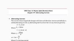
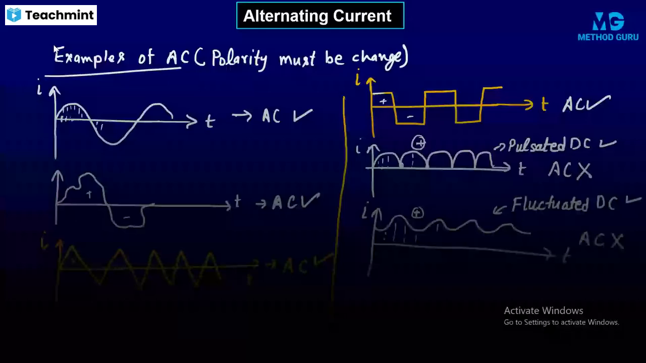
Alternating Current, , Batch - PARAKRAM, ❑ Direct Current (DC), , ✓ If the magnitude and direction of current do not change with time then it is called direct current, ✓ Frequency of DC is Zero and time period is infinite., , R, I, t, , V, , ❑ Alternating Current (AC) or Alternating Voltage, An alternating current/voltage is one whose magnitude changes, continuously with time between zero and a maximum value and whose, direction reverses periodically., R, +, (a), , T, , e/i, , –, , (b), , e/i, , t, , T, , +, –, (Cosinusodial), , (Sinusoidal), , +, , t, , (c), , e/i, , T, –, , t, , (Triangular), , (d), , e/i, , T, , +, –, , t, , (Rectangular/T square), , ➢ Equation for i and VGenerally sinusoidal waveform is used as alternating current/voltage., , i = i0 sint = i0 sin 2 t = i0sin 2 t, T, where V and i are Instantaneous values of current and voltage, i0 and V0 are peak values of current and voltage, , V = V0 sin t = V0 sin 2t = V0 sin, , 2, t, T, , = Angular frequency in rad/sec, = Frequency in Hz and T = time period, ➢ Peak value or Amplitude (i0 and V0 )-, , V or i, , The maximum value of alternating quantity (i or V), is defined as peak value or amplitude., V0, , ➢ Peak to peak value, , T/2, T/4, -V0, , T or 2𝜋, 3T/4, , t or 𝜃, , It is equal to the sum of the magnitudes of, positive and negative peak values, , Peak to peak value = V0 + V0 = 2V0, ➢ Time period (T ), The time taken to complete one cycle of variations is, called the 'periodic-time' or time-period., , Method Guru - Shashtrinagar, Sultanpur (UP) Mob. 7014344748
Page 4 :
Alternating Current, , Batch - PARAKRAM, ➢ Frequency, , The number of cycle completed by an AC in one second is called the frequency, ✓ Unit of frequency is Hertz (Hz), ✓ The value of AC is zero or maximum 2n times every second. The, direction also changes '2n' times every second., ✓ Frequency of AC supply in India is 50 Hz, (Current or voltage will be zero or maximum, 100 times in one second), , 1, or n =, T, , ➢ Mean or Average value (iav or Vav), for one half cycle t=0 to T/2), , for one complete cycle ( t=0 to T), T, , Idt, iav =, , 0, , T/2, , I or <I> = 0, , T, , iav =, , <V> = 0, , , , , 0, T/2, , 0, , Vav =, , i dt, =, dt, , 2V0, , , , 2i0, , , , = 0.637i0 = 63.7% of, , i0, , = 0.637V0 = 63.7% of V0, , ➢ Mean square value of A.C, The average of square of instantaneous values in one cycle is called mean, square value. It is always positive for one complete cycle, V2 =, , 1, T, , , , T, , 0, , V 2dt =, , V02, 2, , i2 =, , i02, 2, , ➢ Root Mean square (R.M.S.) value or apparent value or effective value of A.C., , irms, , = 0.707 i0 = 70.7% i0, , Vrms =, , V0, 2, , = 0.707 V0 = 70.7% of V0, , ✓, , In general when values of voltage or current for alternating circuits are, given, these are r.m.s. value, ✓ In our houses ac is supplied at 220 V, which is the r.m.s. value of voltage., It's peak value is 2 200 = 311V ., ✓ Rms value is also known as dc equivalent, ➢ Form factor, ➢ Peak factor, The ratio of peak value, The ratio of the R.M.S. value of A.C., and r.m.s. value is called peak, to its average during half cycle is, factor, defined as the form factor of A.C., Form factor =, , 𝒓𝒎𝒔 𝒗𝒂𝒍𝒖𝒆, 𝑨𝒗𝒆𝒓𝒂𝒈𝒆 𝒗𝒂𝒍𝒖𝒆 𝒇𝒐𝒓 𝒉𝒂𝒍𝒉 𝒄𝒚𝒄𝒍𝒆, , Form factor for sinusoidal wave =, , , 2 2, , = 1.11, , Peak factor =, , 𝑷𝒆𝒂𝒌 𝒗𝒂𝒍𝒖𝒆, 𝒓𝒎𝒔 𝒗𝒂𝒍𝒖𝒆, , Peak factor for sinusoidal wave =, , 2 = 1.41, , Method Guru - Shashtrinagar, Sultanpur (UP) Mob. 7014344748
Page 5 :
Batch - PARAKRAM, , Alternating Current, , ➢ PHASE, If a quantity is represented as X = Xo sin (t± f), , Then, , ✓ phase = (t ± f), , ✓ t= Instantaneous phase (changes with time), ✓ f= Initial phase ( Constant with time), ✓ Phase determines the direction as well as magnitude of current/emf, ✓ Unit will be radian., , ➢ Phase difference (Phase constant), The difference between the phases of currents and voltage is called phase, difference., , If, emf and current are given by :, V = V0 sin( t + f1 ), , i = i0 sin( t + f 2 ), , Then phase of current relative to emf = f2 – f1, and phase of emf relative to current = f1 – f2, ➢ Time difference, If phase difference is f1 , then-, , T.D. =, , ➢ Phasor Diagram, A diagram representing alternating current, and alternating voltage (of same frequency) as, vectors (phasors) with the phase angle between, them is called a phasor diagram., , T, f, 2, E0 sint, t, , ➢ Impedance (Z), The opposition(resistance) offered by ac circuits to the flow of ac through, it is defined it's impedance. It’s unit is ohm()., , ➢ Reactance (X), The opposition (resistance) offered by inductor or capacitor or both to the, flow of ac through it is defined as reactance. It is of following two type, , (i) Inductive reactance (XL), , (ii)Capacitive reactance (XC), , Method Guru - Shashtrinagar, Sultanpur (UP) Mob. 7014344748
Page 6 :
Alternating Current, , Batch -PARAKRAM, ✓ Inductive reactance (XL) offered by inductive circuit, for dc- dc = 0 so for dc, XL = 0., , XL = L = 2L, XC =, , ✓ Capacitive reactance (XC) offered by capacitive circuit, , 1, , C, , =, , 1, 2C, , for dc- dc = 0 so for dc XC = ., , ➢ Admittance (Y), , 1, , , , Reciprocal of impedance is known as admittance. It’s unit is mho Y = Z ., , ➢ Susceptance (S), , , , The reciprocal of reactance is defined as susceptance S =, , , ✓ Inductive susceptance, , SL =, , 1, 1, =, X L 2 L, , ✓ Capacitive susceptance, , SC =, , 1, ., X, , 1, = C = 2 C, XC, , ➢ MEASUREMENT OF AC CURRENT AND EMF, ✓ DC ammeter and voltmeter are based on the principle of torque acting on a, moving coil placed in a magnetic field. It works on the principle of magnetic, effect of current. It can not be use for AC measurements., , ✓ Hot wire ammeter and Voltmeters are used for AC measurement. Hot, wire instruments are based on heating effect of current. These devices, gives the RMS values (not the amplitude) of voltage and current., , ➢ Power in ac CircuitsPower is defined as the product of voltage and that component of the current, which is in phase with the voltage., V = V0 sin t, , i = i0 sin( t + f ), =, V, i, sin, , t, sin(, t + f), P, =, Vi, ✓ Instantaneous power - instantaneous, 0 0, , Suppose in ac circuit v and i at time t, , ✓ Average power (True power) - Pav = Vrmsirms cos f =, ✓ Apparent or virtual power-, , Papp = Vrms irms, , ➢ Power Factor, , V0, 2, , ., , i0, 2, , cos f =, , 1, V0i0 cos f, 2, , V i, = 00, 2, , The ratio of apparent power and average power is called power factor. It may be, defined as cosine of the angle of lag or lead, , Power Factor = cos 𝜙 =, , 𝑅, 𝑍, , Method Guru - Shashtrinagar, Sultanpur (UP) Mob. 7014344748
Page 7 :
Alternating Current, , Batch -PARAKRAM, , DIFFERENT TYPES OF A. C. CIRCUITS, 1. Purely Resistive Circuit (R-Circuit), ✓ Reactance = 0,, , R, , Impedance = Resistance = R, E 0 sin t, = I0sin wt, R, , E, , ✓ Current I = R =, , , ~, , where I0 =, , E = E0 sint, , ✓ Current and voltage across a resistance, are in the same phase (f = 0o) ., , E0, R, E0, , I0, , E/I, , ✓ Power factor cos f = 1, , I, , E, , ✓ No energy storage ., ✓ Power (Loss), , 𝐼𝑚, , P = Vrms irms =, , V0 i0, 2, , i, , 𝑉𝑚𝑅, 𝜔𝑡, , V, , Phasor diagram, , 2. Purely Inductive Circuit (L-Circuit), V1, + –, , ✓ Impedance = Reactance= XL = L = 2L, Ldi, dt, , ✓ Current, , , , i = i0 sin t − , 2, , , ~, , V0, V, V0, = 0 =, XL L, 2L, , E, , E = E0 sint, , ✓ Voltage leads or current lags by f, ✓ Power factor cos f = 0, ✓ Energy loss = 0, 1, ✓ Energy stored at time t- U= 𝐿𝐼 2, ✓ Average energy stored=, , i0 =, , 2, 1, 2, 𝐿𝐼𝑟𝑚𝑠, 2, , = 90 o, , I, E/I, , t, , 𝑉𝑚𝐿, , 𝐼𝑚, , Method Guru - Shashtrinagar, Sultanpur (UP) Mob. 7014344748
Page 11 :
Alternating Current, , Batch -PARAKRAM, Resonance frequency:, , Impedance as well as current changes with frequency ( 𝜔 𝑜𝑟 𝑓 ) . For a particular, frequency, impedance of circuit will be minimum and current in the circuit is maximum ., This state is called resonance and the frequency is called resonance frequency., , At resonance, X L = XC, , 0 =, , 1, 0 L =, 0C, , 1, , rad, LC sec, , 0 =, , 1, , Hz (or cps), , 2 LC, , Graphical analysis of resonance circuit:, XL, XL, , Z, , fr, , R, XC, , XC, , fr - Resonance, frequency, , Z=R, , fr, f=fr, , Half power frequencies and band width -, , The frequencies at which the power in the circuit is half of the maximum, power (The power at resonance), are called half power frequencies., The current in the circuit at half power frequencies (HPF) is, 70.7% of maximum current (current at resonance)., R3 < R2 < R 1, , I, , R2, , f2, , or 0.707 or, , ✓ There are two half power frequencies, , = 2 − 1, , R1, , fr, , 2, , ✓ The difference of half power frequencies, is called band width (), , R3, , f1, , 1, , f, , R, = , L, , Quality factor or Q-factorThe characteristic of a series resonant circuit is determined by the, quality factor (Q - factor) of the circuit. Q - factor is large, the, sharpness of resonance curve is more ., , Q - factor =, , Resonant frequency 0, =, Band width, , , Q - factor =, , 1 L, R C, , Method Guru - Shashtrinagar, Sultanpur (UP) Mob. 7014344748
Page 12 :
Batch -PARAKRAM, , Alternating Current, , Wattless CurrentThe component of current which does not contribute to the average, power dissipation is called wattless current, ✓ Instantaneous value of wattless current𝑙 ሶ = 𝑖0 sin 𝜙 cos 𝜔𝑡, ✓ Amplitude of wattless current = 𝑖0 sin 𝜙, ✓ RMS value of wattless current = irms sin f =, ✓ Average value of wattless current = 0, , i0, 2, , sin f, , ✓ The phase difference of wattless current and voltage is always 900, , Choke Coil, It is a device having high inductance and low resistance. It is used to control, current in ac circuits, ✓ For an ideal choke coil R = 0, no electric energy is, wasted , average power P = 0., ✓ In actual practice choke coil is equivalent to a R – L, circuit., ✓ Choke-coil is used in tube-lights, motor etc. in series., Skin Effect, A direct current flows uniformly throughout the cross-section of the conductor. An alternating, current, on the other hand, flows mainly along the surface of the conductor. This effect is, known as skin effect, , Transformer, It is a device which raises or lowers the voltage in ac circuits through mutual, induction, ✓ Transformer does not change the frequency, of input ac, ✓ Transformer works on ac only and never on dc., , Method Guru - Shashtrinagar, Sultanpur (UP) Mob. 7014344748
Page 13 :
Batch -PARAKRAM, , Alternating Current, , Types of transformer, 1. Step up transformer, , 2. Step down transformer, , P, , S, , P, , ➢ It increases voltage, and decreases current, , S, , ➢ It decreases voltage, and increase current, , VS > VP, , VS < VP, , N S > NP, , NS < NP, , ES > EP, , ES < EP, iS > iP, , iS < iP, eS, N, V, i, = S = S = P =k, eP, NP, VP, iS, , k = Transformation ratio, , Efficiency of transformer () % =, , =, , Pout, V i, 100 = S S 100, Pin, VP i P, , Pout, Pout, (P − PL ), 100 =, 100 = in, 100, Pin, (Pout + PL ), Pin, , Losses in transformer, (i) Cu loss (i 2 R), , (ii) Eddy current loss, , (iii) Hysteresis loss, , (iv) Magnetic flux leakage, , (v) Humming losses, , Method Guru - Shashtrinagar, Sultanpur (UP) Mob. 7014344748
 Learn better on this topic