Notes of All Classes, Science & All Subjects Physics Notes 12th - Study Material
Page 4 :
SYLLABUS, , Physics (Class–XII) 2021–22, Time: 3 hours , Units, I, , II, III, , IV, , V, VI, , VII, VIII, , IX, , Max. Marks: 70, No. of Periods, , Electrostatics, 1. Electric Charges and Fields, 2. Electrostatic Potential and Capacitance, Current Electricity, 3. Current Electricity, Magnetic Effects of Current and Magnetism, 4. Moving Charges and Magnetism, 5. Magnetism and Matter, Electromagnetic Induction and Alternating Currents, 6. Electromagnetic Induction, 7. Alternating Current, Electromagnetic Waves, 8. Electromagnetic Waves, Optics, 9. Ray Optics and Optical Instruments, 10. Wave Optics, Dual Nature of Radiation and Matter, 11. Dual Nature of Radiation and Matter, Atoms and Nuclei, 12. Atoms, 13. Nuclei, Electronic Devices, 14. Semiconductor Electronics: Materials, Devices and Simple Circuits, Total, , Unit I: Electrostatics , , Marks, , 24, 16, 18, , 22, 17, 20, , 04, 18, 27, , 08, 12, 15, , 12, , 7, , 150, , 70, , (24 Periods), , Chapter 1: Electric Charges and Fields, Electric Charges; Conservation of charge, Coulomb’s law-force between two point charges, forces between, multiple charges; Superposition principle and continuous charge distribution., Electric field, electric field due to a point charge, electric field lines, electric dipole, electric field due to a, dipole, torque on a dipole in uniform electric field., Electric flux, statement of Gauss’s theorem and its applications to find field due to infinitely long straight wire,, uniformly charged infinite plane sheet and uniformly charged thin spherical shell (field inside and outside)., , Chapter 2: Electrostatic Potential and Capacitance, Electric potential, potential difference; Electric potential due to a point charge, a dipole and system, of charges; Equipotential surfaces; Electrical potential energy of a system of two point charges and of, electric dipole in an electrostatic field., Conductors and insulators; Free charges and bound charges inside a conductor. Dielectrics and electric, polarisation; Capacitors and capacitance; Combination of capacitors in series and in parallel; Capacitance, of a parallel plate capacitor with and without dielectric medium between the plates; Energy stored in a, capacitor.
Page 5 :
Unit II: Current Electricity , , (18 Periods), , Chapter 3: Current Electricity, Electric current; Flow of electric charges in a metallic conductor; Drift velocity; Mobility and their, relation with electric current; Ohm’s law, electrical resistance; V-I characteristics (linear and non-linear),, electrical energy and power; Electrical resistivity and conductivity; Carbon resistors, colour code for, carbon resistors; Series and parallel combinations of resistors; Temperature dependence of resistance., Internal resistance of a cell, Potential difference and emf of a cell, Combination of cells in series and in, parallel, Kirchhoff ’s laws and simple applications, Wheatstone bridge, metre bridge., Potentiometer - principle and its applications to measure potential difference and for comparing EMF of, two cells; Measurement of internal resistance of a cell., , Unit III: Magnetic Effects of Current and Magnetism, , (22 Periods), , Chapter 4: Moving Charges and Magnetism, Concept of magnetic field, Oersted’s experiment., Biot-Savart law and its application to current carrying circular loop., Ampere’s law and its applications to infinitely long straight wire. Straight and toroidal solenoids (only, qualitative treatment); Force on a moving charge in uniform magnetic and electric fields; Cyclotron., Force on a current-carrying conductor in a uniform magnetic field; Force between two parallel currentcarrying conductors-definition of ampere, torque experienced by a current loop in uniform magnetic, field; Moving coil galvanometer-its current sensitivity and conversion to ammeter and voltmeter., , Chapter 5 : Magnetism and matter, Current loop as a magnetic dipole and its magnetic dipole moment; Magnetic dipole moment of a, revolving electron; Magnetic field intensity due to a magnetic dipole (bar magnet) along its axis and, perpendicular to its axis; Torque on a magnetic dipole (bar magnet) in a uniform magnetic field; Bar, magnet as an equivalent solenoid; Magnetic field lines; Earth’s magnetic field and magnetic elements., Para-, dia- and ferro-magnetic substances, with examples. Electromagnets and factors affecting their, strengths, permanent magnets., , Unit IV: Electromagnetic Induction and Alternating Currents, , (20 Periods), , Chapter 6: Electromagnetic Induction, Electromagnetic induction; Faraday’s laws, induced EMF and current; Lenz’s Law, Eddy currents., Self and mutual induction., , Chapter 7: Alternating Current, Alternating currents, peak and RMS value of alternating current/voltage; Reactance and impedance; LC, oscillations (qualitative treatment only); LCR series circuit; Resonance; Power in AC circuits, Power, factor; Wattless current., AC generator and transformer., , Unit V: Electromagnetic Waves , , (04 Periods), , Chapter 8: Electromagnetic Waves, Basic idea of displacement current, Electromagnetic waves, their characteristics, their Transverse nature, (qualitative ideas only)., Electromagnetic spectrum (radio waves, microwaves, infrared, visible, ultraviolet, X-rays, gamma rays), including elementary facts about their uses.
Page 6 :
Unit VI: Optics , , (27 Periods), , Chapter 9: Ray Optics and Optical Instruments, Ray Optics: Reflection of light; Spherical mirrors; Mirror formula; Refraction of light; Total internal, reflection and its applications; Optical fibres; Refraction at spherical surfaces; Lenses; Thin lens formula;, Lensmaker’s formula; Magnification, Power of a lens; Combination of thin lenses in contact; Refraction of, light through a prism., Scattering of light– blue colour of sky and reddish appearance of the sun at sunrise and sunset., Optical instruments: Microscopes and astronomical telescopes (reflecting and refracting) and their, magnifying powers., , Chapter 10: Wave Optics, Wave Optics: Wave front and Huygens’ principle; Reflection and refraction of plane wave at a, plane surface using wave fronts. Proof of laws of reflection and refraction using Huygens’ principle., Interference; Young’s double slit experiment and expression for fringe width, coherent sources and, sustained interference of light; Diffraction due to a single slit; Width of central maximum; Resolving, power of microscope and astronomical telescope, polarisation; Plane polarised light; Brewster’s law;, Uses of plane polarised light and Polaroids., , Unit VII: Dual Nature of Radiation and Matter, , (08 Periods), , Chapter 11: Dual Nature of Radiation and Matter, Dual nature of radiation; Photoelectric effect; Hertz and Lenard’s observations; Einstein’s photoelectric, equation-particle nature of light., Experimental study of photoelectric effect., Matter waves–wave nature of particles; de-Broglie relation; Davisson-Germer experiment (experimental, details should be omitted; only conclusion should be explained)., , Unit VIII: Atoms and Nuclei , , (15 Periods), , Chapter 12: Atoms, Alpha-particle scattering experiment; Rutherford’s model of atom; Bohr model, energy levels, hydrogen, spectrum., , Chapter 13: Nuclei, Composition and size of nucleus; Radioactivity; Alpha, beta and gamma particles/rays and their, properties; Radioactive decay law, half life and mean life., Mass-energy relation; Mass defect; Binding energy per nucleon and its variation with mass number;, Nuclear fission; Nuclear fusion., , Unit IX: Electronic Devices , , (12 Periods), , Chapter 14: Semiconductor Electronics: Materials, Devices and Simple Circuits, Energy bands in conductors; semiconductors and insulators (qualitative ideas only), Semiconductor diode- I-V characteristics in forward and reverse bias; Diode as a rectifier., Special purpose p-n junction diodes: LED, photodiode, Solar cell and Zener diode and their characteristics;, Zener diode as a voltage regulator.
Page 7 :
Design of Question Paper, PHYSICS (Theory), Maximum Marks: 70 Time: 3 hours, S., Total, Approximate, Typology of Questions, No., Marks, Percentage, 1., Remembering: Exhibit memory of previously learned material, by recalling facts, terms, basic concepts, and answers., 27, 38%, Understanding: Demonstrate understanding of facts and ideas, by organizing, comparing, translating, interpreting, giving, descriptions, and stating main ideas, 2., Applying: Solve problems to new situations by applying acquired, 22, 32%, knowledge, facts, techniques and rules in a different way., 3., , Analysing: Examine and break information into parts by, identifying motives or causes. Make inferences and find evidence, to support generalizations, Evaluating: Present and defend opinions by making judgments, about information, validity of ideas, or quality of work based on, a set of criteria., Creating: Compile information together in a different way by, combining elements in a new pattern or proposing alternative, solutions., Total, , 21, , 30%, , 70, , 100%, , Practical: 30 marks, Note:, 1. Internal Choice: There is no overall choice in the paper. However, there will be at least 33%, internal choice., 2. The above template is only a sample. Suitable internal variations may be made for generating, similar templates keeping the overall weightage to different form of questions and typology of, questions same., The changes for classes XI-XII (2021-22) internal year-end/Board Examination are as under:, Classes XI-XII, Year-end, Examination/Board, Examination (Theory), , (2020-21), Existing, �, Objective, , Composition, , (2021-22), Modified, , type, Questions �Competency Based Questions will be, including Multiple Choice, 20%, Question-20%, �These can be in the form of Multiple �Case-based/Sourcebased, Choice Questions, Case- Based, Integrated Questions-10%, Questions, Source Based Integrated, Questions or any other types, �, Short Answer/ Long Answer, Questions- Remaining 70%, �, Objective Questions will be 20 %, �Remaining 60% Short Answer/ Long, Answer Questions- (as per existing, pattern)
Page 8 :
Part-A, , Selected NCERT Textbook Questions, Multiple Choice Questions, Fill in the Blanks, Very Short Answer Questions, Short Answer Questions–I, Short Answer Questions–II, Long Answer Questions, Self-Assessment Test
Page 10 :
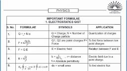
Chapter –1, , Electric Charges, and Fields, , The study of electric charges at rest is called Electrostatics., 1. Two Kinds of Electric Charges, When two bodies are rubbed together, they get oppositely charged. Experimental evidences show, that there are two types of charges:, (i) Positive Charge: Positive charge is produced by the removal of electrons from a neutral body., That is, positive charge means deficiency of electrons., (ii) Negative Charge: Negative charge is produced by giving electrons to a neutral body. That is,, negative charge means excess of electrons on a neutral body., SI unit of charge is coulomb (C)., 2. Properties of Charges, (i) Conservation of Charge: The charge of an isolated system remains constant. This means that, charge can neither be created nor destroyed, but it may simply be transferred from one body, to another., (ii) Additive Property: Total charge on an isolated system is equal to the algebraic sum of charges, on individual bodies of the system. This is called additive property of charges. That is, if a, system contains three charges, q1, q2, – q3, then total charge on system, Q= q1+ q2 – q3., (iii) Quantisation of Charge: The total charge on a body is the integral multiple of fundamental, charge‘e’, i.e., , , q = ± ne , , where n is an integer (n = 1, 2, 3,...)., , (iv) Charge is unaffected by motion: The charge on a body remains unaffected of its velocity, i.e.,, , , Charge at rest = Charge in motion, , (v) Like charges repel while unlike charges attract each other., 3. Coulomb’s Law in General Form, It states that the force of attraction or repulsion between two point charges is directly proportional, to the product of magnitude of charges and inversely proportional to the square of distance, between them. The direction of this force is along the line joining the two charges, i.e.,, q1 q2, F=k 2, r, 1, where k =, is constant of proportionality; ε is permittivity of medium between the charges. If, 4rf, ε0 is permittivity of free space and K the dielectric constant of medium, then ε=Kε0, , Electric Charges and Fields, , 7
Page 11 :
F=, For free space K = 1, Therefore, F=, ∴ , , q1 q2, 1, 4rf0 K r2, 1 q1 q2, , 4rf0 r2, Dielectric constant or Relative permittivity (K): The dielectric constant of a medium is defined as, the ratio of permittivity of medium to the permittivity of free space, i.e., K = ε/ε0, Definition of coulomb: 1 coulomb charge is the charge which when placed at a distance of 1 metre, from an equal and similar charge in vacuum (or air) will repel it with a force of 9 × 10⁹ N., 4. Coulomb’s Law in Vector Form, Consider two like charges q1 and q2 located at points A and B in vacuum. The separation between, the charges is r. As charges are like, they repel each other. Let F21 be the force exerted on charge, q2 by charge q1 and F12 that exerted on charge q1 by charge q2. If r 21 is the position vector of q2, relative to q1 and rt21 is unit vector along A to B, then the force F21 is along A to B and, 1 q1 q2, t ...(i), , F21 =, 4re0 r2 r 21, But, , , rt21 =, F21 =, , r 21, r, 1 q1 q2 r 21, 1 q1 q2, =, r, 2, r, 4rf0 r, 4rf0 r3 21, , Similarly if r 12 is position vector of q1 relative to q2 and rt12 is unit vector from B to A, then, 1 q1 q2, 1 q1 q2, =, t, , F12 =, r ...(ii), r, 4rf0 r2 12, 4rf0 r3 12, Obviously r12 = – r 21 , therefore equation (ii) becomes, ∴ , , F12 = –, , 1 q1 q2, r ...(iii), 4rf0 r3 21, , Comparing (i) and (iii), we get, , , F21 = –F12, , This means that the Coulomb’s force exerted on q2 by q1 is equal and opposite to the Coulomb’s, force exerted on q1 by q2; in accordance with Newton’s third law., Thus, Newton’s third law also holds good for electrical forces., 5. Principle of Superposition of Electric Charges, Coulomb’s law gives the force between two point charges. But if there are a number of interacting, charges, then the force on a particular charge may be found by the principle of superposition. It, states that, , If the system contains a number of interacting charges, then the, force on a given charge is equal to the vector sum of the forces, exerted on it by all remaining charges., The force between any two charges is not affected by the, presence of other charges., Suppose that a system of charges contains n charges ql, q2, q3,, ... qn having position vectors r1, r2, r3, …rn relative to origin O, respectively. A point charge q is located at P having position, , 8, , Xam idea Physics–XII
Page 12 :
vector r relative to O. The total force on q due to all n charges is to be found. If F1, F2, F3, …F n, are, the forces acting on q due to charges ql, q2, q3, ... qn respectively, then by the principle of superposition,, the net force on q is, , , F = F1 + F2 + F3 + … + F n, , If the force exerted due to charge qi on q is F i , then from Coulomb’s law in vector form, qqi, 1, , (r – r i), Fi =, 4rf0 | r – r i | 3, The total force on q due to all n charges may be expressed as, qqi, n, n, 1, , (r – r i), F = / Fi = /, 3, i=1, i = 1 4rf0 | r – r i |, , , =, , qi, n, 1, q /, (r – r i), 4rf0 i = 1| r – r i | 3, , Here ∑ represents the vector-sum., 6. Continuous Charge Distribution, The electrostatic force due to a charge element dq at charge q0 situated at point P is, q0 dq, 1 q0 dq, 1, , dF =, ( r – rl ), R=, 3, 4rf0 R, 4rf0 | r – rl | 3, The total force on q0 by the charged body is, , , F=, , dq (r – rl ), 1, q0 y, 4rf0, | r – rl | 3, , For linear charge distribution, dq = λ dl, where λ is charge per, unit length and integration is over the whole length of charge., For surface charge distribution, dq = σ dS, where σ is charge per, unit area and integration is for the whole surface of charge., For volume charge distribution, dq = ρ dV, where ρ is charge per, unit volume and integration is for whole volume of charge., Electric field, , The electric field strength at any point in an electric field is a vector, quantity whose magnitude is equal to the force acting on a unit positive, test charge and the direction is along the direction of force., If F is the force acting on infinitesimal positive test charge q0, then electric field strength, E =, Therefore from definition, electric field can be given as, , , E = lim, , q0 " 0, , F, ., q0, , F, q0, , The unit of electric field strength is newton/coulomb or volt/metre (abbreviated, as N/C or V/m respectively)., (i) The electric field strength due to a point charge q at a distance r in, magnitude form, , , |E |=, , q, |F |, 1, =, q0, 4rf0 r2, , Electric Charges and Fields, , 9
Page 13 :
1 q, r, 4rf0 r3, (ii) The electric field strength due to a system of discrete charge is, n qi, 1, , E=, / 3 ri, 4rf0 i = 1 r, In vector form, E =, , i, , (iii) The electric field strength due to a continuous charge distribution is, E=, , , , dq, 1, y, r, 4rf0, r3, , 7. Electric field lines, , An electric field line is a curve drawn in such a way that tangent to it at each point is in the direction, of the net field at that point., Properties of electric field lines, (i) Field lines start from positive charges and end at negative charges. If there is a single charge,, they may start or end at infinity., (ii) In a charge-free region, electric field lines can be taken to be continues curves without any, breaks., (iii) No two electric field lines can intersect each other because if they do so, then two tangents, can be drawn at the point of intersection; which would mean two directions of electric field, strength at one point and that is impossible., (iv) The electric field lines do not form any closed loops. This follows from the conservative nature, of electric field., (v) The equidistant electric field lines represent uniform electric field while electric field lines at, different separations represent non-uniform electric field (Figure)., , –, , +, , +, , +, , x, Ex, , +, , y, =, , Ey, , –, , y, , x, Ex, , >, , Ey, , 8. Electric Dipole, A system containing two equal and opposite charges separated by a finite distance is called an, electric dipole. Dipole moment of electric dipole having charges +q and – q at separation 2l is defined, as the product of magnitude of one of the charges and shortest distance between them., , , p = q2 l, , It is a vector quantity, directed from – q to + q, [Remark: Net charge on an electric dipole is zero.], , 10 Xam idea Physics–XII
Page 14 :
9. Electric Field Due to a Short Dipole, (i) At a point P on axis, E =, , 1 2p, 4rf0 r3, , (ii) At a point P´ on equatorial line,, 1 p, , El =, 4rf0 r3, 10. Electric Force and Torque on an Electric Dipole in a Uniform Electric Field, In a uniform electric field of strength E, the net electric, force is zero; but a torque equal to pE sin θ acts on the dipole, (where θ is the angle between directions of dipole moment, p and electric field E ). This torque tends to align the dipole, along the direction of electric field. Torque in vector form, x = p#E., 11. Electric Flux, The total number of electric field lines crossing (or diverging) a, surface normally is called electric flux., Electric flux through surface element dS is Tz = E.dS = EdS cos θ,, , dS, , where E is electric field strength., Electric flux through entire closed surface is, z = y E . dS, S, , SI unit of electric flux is volt-metre or Nm2C–1., 12. Gauss’s Theorem, , 1, It states that the total electric flux through a closed surface is equal to, times the net charge, f0, enclosed by the surface, 1, i.e., , z = y E . dS = /q, f, S, 0, 13. Formulae for Electric Field Strength Calculated from Gauss’s Theorem, , E, , (a) Electric field due to infinitely long straight wire of charge per unit, length λ at a distance r from the wire is, 1 2m, E =, 4rf0 r, (b) Electric field strength due to an infinite plane sheet of charge per unit, area σ is, v, , E=, , independent of distance of point from the sheet., 2f 0, , r, , (c) Electric field strength due to a uniformly charged thin spherical shell or conducting sphere, of radius R having total charge q, at a distance r from centre is, 1 q, (i) at external point Eext =, (For r > R), E, 4rf0 r2, q, 1, E∝1/r2, (ii) at surface point ES =, (For r = R), 4rf0 R2, (iii) at internal point Eint = 0, , (For r < R), , E=0, , r, , Electric Charges and Fields 11
Page 15 :
(d) Electric field strength due to a uniformly charged non-conducting solid sphere of radius R, at a distance r from centre, 1 q, (i) at external point Eext =, (For r > R), E, 4rf0 r2, (For r = R), (For r < R), , E∝1/r2, , E∝, r, , q, 1, 4rf0 R2, 1 qr, (iii) at internal point, Eint =, 4rf0 R3, (ii) at surface point ES =, , R, , Selected NCERT Textbook Questions, Quantisation of Charge, Q. 1. A polythene piece rubbed with wool is found to have a negative charge of 3 × 10⁻⁷ C., (a) Estimate the number of electrons transferred (from which to which?)., (b) Is there a transfer of mass from wool to polythene?, Ans. When two neutral bodies are rubbed together, electrons of one body are transferred to the, other. The body which gains electrons is negatively charged and the body which loses electrons, is positively charged., , (a) From quantisation of charge, , q = ne, Here, q = 3×10 –7 C, e = 1.6×10 –19 C, q, 3×10 –7, = 1.875×10¹², , ∴ Number of electrons transferred, n = e =, 1.6×10 –19, When polythene is rubbed with wool, the polythene becomes negatively charged and wool, becomes positively charged. This implies that the electrons are transferred from wool to, polythene., (b) Yes as electrons have finite mass, the mass is transferred from wool to polythene., , DM = n × m = 1.875×1012 × 9.1×10 –31 kg = 1.7 × 10 –18 kg, e, , Coulomb’s Law, , Q. 2. What is the force between two small charged spheres having charges of 2 × 10⁻⁷ C and, 3 × 10⁻⁷ C placed 30 cm apart in air?, Ans. Two charged spheres at finite separation behave as point charge and the Coulomb’s force of, repulsion, 1 q1 q2, , F=, 4rf0 r2, , Here, q1 = 2×10 –7 C, q2 = 3×10 –7 C, r = 30 cm = 0.30 m, (2×10 –7) × (3×10 –7), , = 6×10 –3 N, (0.30) 2, Q. 3. The electrostatic force on a small sphere of charge 0.4 µC due to another small sphere of, charge – 0.8 µC in air is 0.2 N., (a) What is the distance between the two spheres?, (b) What is the force on the second sphere due to the first?, Ans. The electrostatic force between two charged spheres is given by Coulomb’s law as, q1 q2, 1, , F=, 4rf0 r2, , ∴, , 9, , F = 9×10 ×, , -, , Here q1 = 0.4 nC = 0.4 # 10 6 C,, , 12 Xam idea Physics–XII
Page 16 :
q2 = –0.8 nC = –0.8 # 10 –6 C = 0.8 # 10 –6 (magnitude), F = 0.2 N, (a) As charges are of the opposite sign, the force between the charges magnitude is attractive, , , `, , 0.2 =9 # 109 #, , ⇒, , , r2 =, , (0.4 # 10 –6) # (0.8 # 10 –6), r2, , 9 × 109 × (0.4 × 10−6 ) × (0.8 × 10⁻⁶ ), = 9 × 16 × 10−4, 0.2, , Distance, r = 12 # 10 –2 m = 12 cm, (b) The force on second sphere due to first is = 0.2 N. Since | F 21 | = | F 12 |, Q. 4. Four point charges qA = 2 µC, qB = – 5 µC, qC = 2 µC and qD = – 5 µC are located at the corners, of a square ABCD of side 10 cm. What is the force on a charge of 1 µC placed at the centre of, the sphere?, Ans. The coulomb’s forces acting on a charged particle due to, all other charges are added by vector method. Force on, charge q0=1 µC placed at centre O will be the vector sum, of forces due to all the four charges qA, qB, qC and qD., Clearly, OA=OB=OC=OD, , q0, , 10 2, 1, cm, 102 + 102 =, 2, 2, = 5 2 cm = 5 2 ×10 –2 m, =, , , , , Force on q0=1µC due to charge q A = 2 nC is, , , F OA =, , q0 q A, ^1×10 –6 h^2×10 –6 h, 1, 9, =, = 3.6 N along OC, along, OC, 9, ×, 10, ×, 2, 4re0 ^OA h2, ^5 2 ×10 –2 h, , Force on q0 =1 µC due to charge qC, , , FOC =, , = 2 nC is, , q0 qC, (1 # 10 –6) (2 # 10 –6), 1, 9, =, #, #, = 3.6 N along OA, along, OA, 9, 10, 4rf0 (OC) 2, (5 2 # 10 –2) 2, , Clearly, FOA + FOC = 0, The force on q0 =1 µC due to charge qB =–5 µC is, q0 qB, (1 # 10 –6) (5 # 10 –6), 1, 9, =, #, #, along, OB, 9, 10, along OB = 9.0 N along OB, 4rf0 (OB) 2, (5 2 # 10 –2) 2, The force on q0 =1 µC due to charge qD =–5 µC is, q0 qD, 1×10 –6 ×5×10 –6, 1, 9, =, = 9.0 N along OD, , FOD =, along, OD, 9, ×, 10, ×, 2, 4re0 ^, –2 2, ^, h, h, , F OB =, , OD, , Clearly,, , ", ", FOB + FOD, , 5 2 ×10, , =0, , Therefore, net force on q0 is, , , F = FOA + FOB + FOC + FOD = (FOA + FOC) + (FOB + FOD) = 0 + 0 = 0, , , that is, the net force on charge q0 is zero., Q. 5. (a) Two insulated charged copper spheres A and B have their centres separated by a distance, of 50 cm. What is the mutual force of electrostatic repulsion if the charge on each is 6.5 × 10⁻⁷C?, The radii of A and B are negligible compared to the distance of separation., (b) What is the force of repulsion if each sphere is charged double the above amount, and the, distance between them is halved?, , Electric Charges and Fields 13
Page 17 :
(a) Here, q1 = 6.5 × 10⁻⁷ C, q2= 6.5 × 10⁻⁷ C, r = 50 cm = 0.50 m, 1, = 9 # 109 Nm2 C –2, , k=, 4rf0, q1 q2, 9×109 ×6.5×10 –7 ×6.5×10 –7, Using Coulomb’s law, F = k 2 =, N, r, (0.50) 2, Ans., , 380.25 # 10 –5, N = 1521 × 10–5 N = 1.5 × 10⁻² N, 0.25, (b) If each sphere is charged double and the distance between them is halved, then the force of, repulsion is given by, 2q1 ×2q2, q1 q2, = 16k 2 = 24 # 10 –2 N = 0.24 N, , F=k, 2, (r/2), r, , , =, , Q. 6. Suppose the spheres A and B in above question have identical sizes. A third sphere of the, same size but uncharged is brought in contact with the first, then brought in contact with the, second, and finally removed from both. What is the new force of repulsion between A and B?, Ans. Charge on each spheres A and B = q = 6.5 × 10⁻⁷ C when a similar but uncharged sphere C is, q, brought in contact with sphere A, each sphere shares a charge , equally., 2, q, q, , Charge = 0, 2, , A, , 2, , A, , , Now, when the sphere C is brought in contact with sphere B, the charge is redistributed equally., , , Charge of sphere B or C =, , 4, , Now, , , , , , q 3q, 1, q+ =, , 2, 2 4, , F=, , 1, 4rf0, , q 3q, ., 2 4, r, , 2, , =, , 4, , 3, # 1.5 # 10 –2 N = 5.6 # 10 –3 N, 8, , Electric Field, Q. 7. Two point charges qA =+ 3 µC and qB = – 3 µC are located 20 cm apart in vacuum. (a) What is, the electric field at the mid point O of the line AB joining the two charges? (b) If a negative test, charge of magnitude 1.5×10⁻⁹ C is placed at this point, what is the force experienced by the, test charge?, Ans. (a) The electric field strength at point O due, O, to charges A and B is additive (away from, positive charge and towards negative charge), , ∴ Electric field strength at mid point due to, charge qA is, 3×10 –6, 1 qA, = 9×10⁹ ×, = 2.7×10⁶ NC –1 along AO, , E1 =, 2, 2, 4re0 r, ^0.10h, Electric field strength at O due to charge qB, 3×10 –6, 1 qB, 9, =, = 2.7×10⁶ NC –1 along OB, , E2 =, 9, ×, 10, ×, 2, 4re0 r2, ^0.10h, , 14 Xam idea Physics–XII
Page 18 :
Net electric field at O, ", , , E = E1 + E2 = 2.7 # 106 + 2.7 # 106 = 5.4 # 106 NC –1 along AB, (b) Electric force on test charge q0 placed at O, , F = q0 E = 1.5×10 –9 × 5.4×106 = 8.1×10 –3 N, Q. 8. A system has two charges qA = 2.5 × 10⁻⁷ C and qB = – 2.5 × 10⁻⁷ C located at points A = (0, 0, –15 cm), and B=(0, 0, +15 cm) respectively. What are the total charge and electric dipole moment of, the system?, Ans. A dipole has two equal and opposite charges with dipole moment, ", , ", , p = q2l, directed from –q to + q., Given, q A = 2.5 # 10 –7 C, qB = –2.5 # 10 –7 C, , , , Total ch arg e, q = q A + qB = 2.5 # 10 –7 C–2.5 # 10 –7 C = 0., 2l = AB = 30 cm = 0.30 m, , , , ", , ", , Electric dipole moment, p = q2 l directed from –q to +q, , = ^2.5×10 –7 Ch_0.30 m) = 7.5×10 –8 Cm along BA, , = 7.5 × 10⁻⁸ Cm directed along negative Z-axis., Q. 9. An electric dipole with a dipole moment 4×10⁻⁹ Cm is aligned at 30° with the direction of a, uniform electric field of magnitude 5×10⁴ NC–1 Calculate the magnitude of the torque acting, on the dipole., Ans. A dipole placed in a uniform electric field, experiences a torque τ = pE sin θ which tends to align, the dipole parallel to the direction of field., Torque τ = pE sin θ, p = 4×10⁻⁹ C-m, E = 5×10⁴ NC–1, θ = 30°, Torque τ = 4×10–9 ×5 ×104 sin 30°, 1, = 4×10– 9× 5 ×104 × =10– 4 Nm, 2, Q. 10. The figure shows tracks of three charged particles in a uniform electrostatic field. Give the, signs of the three charges. Which particle has the highest charge to mass ratio?, , Here, ∴, , , 1, , A, ++++++++++++++++, , C, , ––––––––––––––––, B, , 3, , 2, , y, , x, , Ans. A positively charged particle is deflected towards a negative plate and a negatively charged, particle towards a positive plate and shows a parabolic path., From fig. it is clear that the particles (1) and (2) are deflected towards positive plate; hence, they, carry negative charges., Particle (3) is deflected along negative plate, so it carries positive charge., The transverse deflection in a given electric field is, qE, 1, x, , y = at2, where a = m and t = b u l, 2, So, , y=, , q, 1 q E x2, c m, \ m., 2 m u2, , From fig., it is obvious that the transverse deflection is the maximum for particle (3), hence,, particle (3) has the highest charge to mass ratio (q/m)., , Electric Charges and Fields 15
Page 19 :
Q. 11. A conducting sphere of radius 10 cm has an unknown charge. If the electric field 20 cm from, the centre of sphere is 1.5 × 10³ NC–1 and points radially inward, what is the net charge on the, sphere?, Ans. Given, radius of sphere R = 10 cm = 0.10 m, Distance from centre, r = 20 cm = 0.20 m, Electric field at distance r from centre, E = 1.5 × 10³ NC–1, The electric field due to charged sphere at external point distance r from centre is, 1 q, , E=, 4re0 r2, , ∴ Substituting the given values,, q, , 1.5 # 103 = 9 # 109 #, (0.20) 2, 1.5×10³ ×^0.20h, , 2, , , ⇒ Charge on sphere, q =, , 9×10⁹, , = 6.67×10 –9 C = 6.67 nC, , As electric field is radially inward, charge on sphere is negative, therefore, charge on sphere, = – 6.67 nC., Q. 12. An infinite line charge produces an electric field of 9 × 10⁴ NC–1 at a distance of 2 cm., Calculate the linear charge density., m, 1 2m, =, Ans. Electric field at a distance r from an infinite line charge is, E =, 2rf0 r, 4rf0 r, 1, , ∴ Linear charge density m = (4rf0) r E, 2, Here, r =2 cm = 0.02 m, E = 9 × 10⁴ NC–1, 1, 1, #, # (0.02) # (9 # 10 4) = 10 –7 C m –1, 2 d 9 # 109 n, , m=, , , `, , Q. 13. An oil drop of 12 excess electrons is held stationary under a constant electric field of 2.55 × 10⁴ NC–1, in Millikan’s oil drop experiment. The density of the oil is 1.26 g cm–3. Estimate the radius of the, drop (g = 9.81 ms–2; e = 1.60 × 10⁻¹⁹ C)., Ans. In Millikan’s oil drop experiment, the charged oil drop remains suspended (in equilibrium) when, downward weight of drop is balanced by upward electrostatic force and charge on drop, q = ne, i.e.,, , , qE = mg, , &, , neE = mg, , If r is radius of oil drop, then mass m =, , `, , neE =, , , &, , r==, , 4 3, rr tg, 3, , 4 3, rr t, 3, , 1/3, , 3neE, G, 4rtg, , Here, n = 12, e = 1.6×10 –19 C, E = 2.55×10 4 NC –1, t = 1.26 g cm –3 = 1.26×10³ kg m –3,, , g = 9.81 ms –2, , `, , r==, , 1/3, , 3 ×12 ×1.6 ×10 –19 × 2.55 ×10 4, G, 4 × 3.14 ×1.26 ×1000 × 9.81, , 3×12×1.6×2.55×1000 1/3, F ×10 –7 m, 4×3.14×1.26×9.81, , , , =<, , , , = 9.81×10 –7 m = 9.81×10 –4 mm, , 16 Xam idea Physics–XII
Page 20 :
Q. 14. A particle of mass m and charge (–q) enters the region between the two charged plates initially, moving along X-axis with speed vx as shown in fig. The length of plate is L and an uniform, electric field E is maintained between the plates. Show that the vertical deflection of the, qEL2, particle at the far edge of the plate is, [HOTS], . , 2mv x2, , qE, Ans. Force on particle towards upper plate B, Fy = qE vertical acceleration of particle, a y = m ., Initial vertical velocity vy = 0, Speed of particle along X-axis =vx (constant), L, Time taken by particle between the plates, t = v, x, From relation s = ut +, y=, , &, , qEL2, , 1, 1 qE L 2, 1 2, at vertical deflection y = 0 + a y t2 = 0 + c m mc v m, 2, 2, 2, x, , 2mv 2x, , Q. 15. Suppose that the particle in above question is an electron projected with velocity vx = 2.0 ×, 106 m/s. If electric field between the plates separated by 0.5 cm is 9.1 × 10² N/C, where will the, electron strike the upper plate? (|e|=1.6 × 10⁻¹⁹ C, me = 9.1 × 10⁻³¹ kg.), [HOTS], + + + + + + + +, Ans. Vertical deflection for distance x along X-axis is, , , y=, , qEx2, 2mv 2x, , & x=, , 2my, v, qE x, , ymax, , Given m =9.1×10⁻³¹ kg, y = 0.5 cm=0.5×10⁻² m,, 6, , –1, , vx = 2.0 # 10 ms , q = | e | = 1.6 # 10, , , `x=, =, , –31, , –19, , –, , –, , –, , –, , –, , –, , –, , –, , 2, , C, E = 9.1 # 10 N/C., , –2, , 2 # 9.1 # 10 # 0.5 # 10, # 2.0 # 106 m, 1.6 # 10 –19 # 9.1 # 102, 1, # 10 –8 # 2.0 # 106 . 0.8 # 2 ×10 –2 m = 1.6×10 –2 m = 1.6 cm, 1.6, , Electric Flux, Q. 16. Consider a uniform electric field E = 3×10 3 it NC –1 . (a) What is the flux of this field through, a square of 10 cm on a side whose plane is parallel to the yz plane? (b) What is the flux through, the same square if the normal to its plane makes a 60° angle with the x-axis?, Ans. Given electric field E = 3×10³ itNC –1 ,, Magnitude of area, S=10 cm×10 cm=0·10 m×0·10 m=1×10⁻² m2, (a) When plane is parallel to YZ plane, the normal to plane is along X-axis., , `, z = ES cos i, , , = 3×103 ×1×10 –2 cos 00 (a i = 00) = 30 Nm2 C –1, , Electric Charges and Fields 17
Page 21 :
(b) In this case θ = 60o , so electric flux, z = ES cos i, , , = 3×103 ×1×10 –2 cos 60 o = 30×, , 1, = 15 Nm2 C –1 ., 2, , Q. 17. What is the net flux of the uniform electric field E = 3×10³ it N/C through a cube of side, 20 cm oriented so that its faces are parallel to the coordinate planes?, Ans. Electric field is along positive X-axis. The flux through, two faces [1 and 2] Y-Z plane is zero., For face 1, flux = ES cos 180° = – ES, For face 2, flux = ES cos 0° = ES, Net flux through faces 1 and 2 = ES – ES = 0, The electric flux through faces in XZ plane is zero because, E .S = ESxz cos 90 o = 0 o ., The electric flux through faces in XY plane is zero because, " ", , E.Sxy = ESxy cos 90° = 0 ., , ∴ Net electric flux through cube is zero., Q. 18. Careful measurement of the electric field at the surface of a black box indicate that the net, outward flux through the surface of the box is 8.0 × 10³ Nm2/C., , (a) What is the net charge inside the box?, (b) If the net outward flux through the surface of the box were zero, could you conclude that, there were no charges inside the box? Why or Why not?, Ans. (a) Given electric flux z = 8.0×10³ Nm2 C –1, 1, From Gauss’s theorem z = f q, 0, , ∴ Charge enclosed, q = f0 z = 8.85×10 –12 ×8.0×103 = 70.8×10 –9 C = 70.8 nC, (b) If the net outward flux is zero, it indicates that the net charge enclosed in the blackbox is, zero. The conclusion is either (i) there is no charge inside the box or (ii) there may be different, types of charges in the box such that the algebraic sum of charges inside the box is zero., Q. 19. A point charge + 10 µC is at a distance 5 cm directly above the, q = 10 µC, the centre of a square of side 10 cm as shown in figure. What, 5 cm, is the magnitude of the electric flux through the square? [Hint:, Think of the square as one face of a cube with edge 10 cm], [HOTS], Ans. Obviously the given square ABCD of side 10 cm is one face of a, cube of side 10 cm. At the centre of this cube a charge + q=10 µC, 10 cm, is placed., According to Gauss’s theorem, the total electric flux through the, q, six faces of cube= f ., 0, , 18 Xam idea Physics–XII, , 10 cm
Page 22 :
∴, , , , , Total electric flux through square, 1 q, = f, 6 0, 10 # 10 –6, 1, #, 6 8.85 # 10 –12, = 1.88 × 10⁵ Nm2C–1., =, , Q. 20. A point charge of 2.0 nC is at the centre of a cubic Gaussian surface 9.0 cm on edge. What is, the net electric flux through the surface?, Ans. Given q = 2.0 nC = 2.0×10 –6 C, Net electric flux through the cubical surface, q, 2.0 ×10 –6, = 2.26×10 5 Nm2 C –1, , zE = f =, 0, 8.85 ×10 –12, Q. 21. A point charge causes an electric flux of – 1.0 × 10³ Nm2 C–1 to pass through a spherical, surface of 10.0 cm radius centred on the charge., (a) If the radius of the Gaussian surface were doubled, how much flux would pass through the, surface?, (b) What is the value of the point charge?, Ans. (a) The electric flux through a surface depends only on the charge enclosed by the surface., If the radius of the spherical surface is doubled, the charge enclosed remains the same, so, the electric flux passing through the surface will remain unchanged., q, (b) If q is the point charge, then by Gauss theorem, the electric flux z E =, f0, , ⇒ , , q=ε0 φE= 8.85×10⁻¹² × (– 1.0 × 10³) = – 8.85 × 10⁻⁹ C, , Q. 22. A uniformly charged conducting sphere of 2.4 m diameter has a surface charge density of, 80.0 nC /m2 (a) Find the charge on the sphere. (b) What is the total electric flux leaving the, surface of the sphere?, 2. 4, Diameter, =, Ans. (a) Radius of sphere r =, m = 1.2 m, 2, 2, Surface charge density v = 80.0 nC/m2 = 80.0×10 –6 C/m2, Charge on sphere Q = v×4rr2, = 80.0 ×10 –6 × 4 × 3.14 ×(1.2) 2 = 1.45 × 10 –3 C, , , (b) Total electric flux leaving the surface of the sphere, q, 1.45×10 –3, = 1.6×10⁸ Nm2 C –1, , zE = f =, 0, 8.85×10 –12, Q. 23. Two large, thin metal plates are parallel and close to each other. On their inner faces, the, plates have surface charge densities of opposite signs and of magnitude 17.0 × 10⁻²² C/m2, What is electric field strength E: (a) in the outer region of the first plate, (b) in the outer region, of the second plate, and (c) between the plates?, v, Ans. The electric field due to each surface charge =, 2f 0, Given σ = 17.0 × 10⁻²² C/m2, (a) The electric field in the outer region of first plate (point P)., v, v, = E2 – E1 =, =0, , –, 2f 0 2f 0, , Electric Charges and Fields 19
Page 23 :
(b) The electric field in the outer origin of second plate (point Q )., v, v, = E1 – E2 =, =0, , –, 2f 0 2f 0, (c) The electric field between the plates, v, v, +, , E = E1 + E2 =, 2f 0 2 f 0, v, 17.0 # 10 –22, =f =, = 1.92 # 10 –10 N/C, –12, 0, #, 8.85 10, , , , Multiple Choice Questions, , [1 mark], , E, , E, , Choose and write the correct option(s) in the following questions., 1. A body can be negatively charged by, (a) giving excess of electrons to it, (b) removing some electron from it, (c) giving some protons to it, (d) removing some neutrons from it., 2. How many electrons must be removed from an electrically neutral metal plate to give it a, positive charge of 1 × 10⁻⁷ coulomb?, (a) 6.25 × 10¹¹, (b) 6.45 × 10¹³, (c) 6.25 × 10⁻¹¹, (d) 6.45 × 10⁻¹³, 3. The unit of permittivity of free space (e0) is, (a) CN–1m–1, (b) Nm2C–2, (c) C2 N–1m–2, (d) C2 N–2m–2, 4. Which of the following is not a property of field lines?, (a) Field lines are continuous curves without any breaks, (b) Two field lines cannot cross each other, (c) Field lines start at positive charges and end at negative charges, (d) They form closed loops, 5. Gauss's law is valid for, (a) Any closed surface , (b) Only regular closed surfaces, (c) Any open surface , (d) Only irregular open surfaces., 6. The spatial distribution of the electric field due to two charges (A, B) is shown in figure., , Which one of the following statements is correct?, (a) A is + ve and B is – ve and |A|>|B|, (b) A is – ve and B is + ve, |A|=|B|, A, B, (c) Both are + ve but A>B, (d) Both are – ve but A>B, 7. The electric field due to a uniformly charged sphere of, radius R as a function of the distance from its centre is represented graphically by, (a), (b), , O, , R, , O, , r, , r, , R, , r, , O, , E, , (d), , E, , (c), , R, , R, , 20 Xam idea Physics–XII, , r, , O
Page 24 :
8. When air is replaced by a medium of dielectric constant K, the force of attraction between two, charges separated by a distance r, (a) decreases K times , (b) remains unchanged, (c) increases K times , (d) increases K–2 times, 9. A point positive charge is brought near an isolated conducting sphere (Fig. given below). The, electric field is best given by , [NCERT Exemplar], , +q, , q, (i), , (ii), , +q, , +q, (iii), (a) Fig (i), , (iv), , (b) Fig (ii), , (c) Fig (iii), , (d) Fig (iv), , 10. The Electric flux through the surface�, , [NCERT Exemplar], S, , S, +, , q, , (i), (a), (b), (c), (d), , S, , S, +, +, , q, , (ii), , q, , (iii), , +, , q, , (iv), , in Fig. (iv) is the largest., in Fig. (iii) is the least., in Fig. (ii) is same as Fig. (iii) but is smaller than Fig. (iv), is the same for all the figures., , 11. A hemisphere is uniformly charged positively. The electric field at a point on a diameter away, from the centre is directed�, [NCERT Exemplar], (a) perpendicular to the diameter, (b) parallel to the diameter, (c) at an angle tilted towards the diameter (d) at an angle tilted away from the diameter, 12. A point charge +q, is placed at a distance d from an isolated conducting plane. The field at a, point P on the other side of the plane is, (a) directed perpendicular to the plane and away from the plane., (b) directed perpendicular to the plane but towards the plane., (c) directed radially away from the point charge., (d) directed radially towards the point charge., 13. Figure shows electric field lines in which an electric dipole p is, placed as shown. Which of the following statements is correct?, �, [NCERT Exemplar], (a) the dipole will not experience any force., p, (b) the dipole will experience a force towards right., –q, +q, (c) the dipole will experience a force towards left., (d) the dipole will experience a force upwards., , Electric Charges and Fields 21
Page 25 :
14. A point charge +q, is placed at a distance d from an isolated conducting plane. The field at a, point P on the other side of the plane is�, [NCERT Exemplar], (a) directed perpendicular to the plane and away from the plane., (b) directed perpendicular to the plane but towards the plane., (c) directed radially away from the point charge., (d) directed radially towards the point charge., 15. There are two kinds of charges—positive charge and negative charge. The property which, differentiates the two kinds of charges is called, (a) amount of charge , (b) polarity of charge, (c) strength of charge , (d) field of charge, 16. A method for charging a conductor without bringing a charged object in contact with it is called, (a) electrification , (b) magnetisation, (c) electromagnetic induction, (d) electrostatic induction, 17. If y E .dS = 0 over a surface, then�, [NCERT Exemplar], (a) the electric field inside the surface and on it is zero., (b) the electric field inside the surface is necessarily uniform., (c) the number of flux lines entering the surface must be equal to the number of flux lines, leaving it., (d) all charges must necessarily be outside the surface., 18. A cup contains 250 g of water. The number of negative charges present in the cup of water is, (a) 1.34 × 10⁷ C, (b) 1.34 × 10¹⁹ C, (c) 3.34 × 10⁷ C, (d) 1.34 × 10⁻¹⁹ C, 19. When the distance between two charged particles is halved, the Coulomb force between them, becomes, (a) one-half, (b) one-fourth, (c) double, (d) four times., 20. Two charges are at distance d apart in air. Coulomb force between them is F. If a dielectric, material of dielectric constant K is placed between them, the Coulomb force now becomes, (a) F/K, (b) FK, (c) F/K2, (d) K2F, 21. Two point charges q1 and q2 are at separation r. The force acting between them is given by, q1 q2, F = K 2 . The constant K depends upon, r, (a) only on the system of units, (b) only on medium between charges, (c) both on (a) and (b) , (d) neither on (a) nor on (b), 22. Which among the curves shown in figure possibly represent electrostatic field lines?, , , , (a) (b), , (c) , , (d), , 23. Three charges +4q, Q and q are placed in a straight line of length l at points at distance 0, l/2,, and l respectively. What should be Q in order to make the net force on q to be zero?, q, (a) –q, (b) –2q, (c) –, (d) 4q, 2, 24. An electron falls from the rest through a vertical distance h in a uniform and vertically upward, directed electric field E. The direction of electric field is now reversed, keeping its magnitude, the same. A proton is allowed to fall from rest in it through the same vertical distance h. The, time of fall of the electron, in comparison to the time of fall of the proton is, (a) smaller, (b) 5 times bigger, (c) 10 times bigger, (d) equal, , 22 Xam idea Physics–XII
Page 26 :
25. Two point charges A and B, having charges +q and –q respectively, are placed at certain, distance apart and force acting between them is F. If 25% charge of A is transferred to B, then, force between the charges becomes:, 9F, 16F, 4F, (a) F, (b), (c), (d), 16, 3, 3, , Answers, 1., 7., 13., 19., , (a), (b), (c), (d), , 2., 8., 14., 20., , (a), (a), (a), (a), , 3., 9., 15., 21., , (c), (a), (b), (c), , 4., 10., 16., 22., , (d), (d), (d), (b), , 5., 11., 17., 23., , (a), (a), (c), (d), (a), , Fill in the Blanks, 1., 2., 3., 4., 5., 6., 7., 8., 9., 10., , 6., 12., 18., 24., , (a), (a), (a), (a), , 25. (b), , [1 mark], , The quantisation of charge was experimentally demonstrated by _______________ in 1912., The value of the permittivity of free space (e0) in SI unit is _______________., A simple apparatus to detect charge on a body is the _______________., The process of sharing the charges with the earth is called _______________., The concept of field was first introduced by _______________ and is now among the central, concepts in physics., Two point charges are separated by some distance inside vacuum. When space between the, charges is filled by some dielectric, the force between two point charges _______________., Two point charges, one coulomb each are separated by vacuum and placed I meter apart from, each other. The force acting between them is _______________., Direction of electric field intensity due to a dipole on equatorial point is _______________ to the, direction of dipole moment., Two equal and opposite charges of magnitude 0.2 × 10⁻⁶ C are 15 cm apart, the magnitude and, direction of the resultant electric intensity E at a point midway between the charge is ___________., A proton at rest has a charge e. When it moves with high speed v, its charge is _______________., , Answers, 1. Millikan, , 2. 8.854 × 10⁻¹² C2N–1m–2, , 4. grounding or earthing, 8. opposite, , 5. Faraday, , 3. gold-leaf electroscope, 6. decreases, , 9. 6.4 × 10⁵ N/C, towards the –ve charge, , Very Short Answer Questions, , 7. 9 × 10⁹ N, 10. e, , [1 mark], , Q. 1. Sketch the electric field lines for two point charges q1 and q2 for q1 = q2 and q1 > q2 separated, by a distance d. , [CBSE Chennai 2015] [CBSE 2019 (55/2/3)], Ans. When the charges are equal, the neutral point N lies at the centre of the line joining the charges., However, when the charges are unequal, the point N is closer to the smaller charge., , Electric Charges and Fields 23
Page 27 :
Q. 2 Draw the pattern of electric field lines, when a point charge –Q is kept, near an uncharged conducting plate., [CBSE 2019 (55/1/1)], Ans. As –Q charge is kept near an uncharged conducting plate, positive, charge is induced on the plate due to electrostatic induction. The field, lines will be perpendicular to the metal surface., Q. 3. Why do the electrostatic field lines not form closed loops?, , [CBSE (AI) 2014, Allahabad 2015], Ans. Electric field lines start from positive charge and terminate at negative, charge. If there is a single positive charge, the field lines start from the, charge and terminate at infinity. So, the electric field lines do not form closed loops., Q. 4. Does the charge given to a metallic sphere depend on whether it is hollow or solid? Give, reason for your answer., [CBSE Delhi 2017], Ans. No, Reason: This is because the charge resides only on the surface of the conductor., Q. 5. Two identical conducting balls A and B have charges –Q and +3Q respectively. They are, brought in contact with each other and then separated by a distance d apart. Find the nature, of the Coulomb force between them., [CBSE 2019 (55/4/1)], Ans. Final charge on balls A and B =, , 3Q – Q, =Q, 2, , The nature of the coulomb force between them is repulsive., Q. 6. Two insulated charged copper spheres A and B of identical size have charges qA and qB, respectively. A third sphere C of the same size but uncharged is brought in contact with the, first and then in contact with the second and finally removed from both. What are the new, charges on A and B?, [CBSE (F) 2011], qA, q A + 2q B, Ans. New charge on A is, and new charge on B is, ., 2, 4, Q. 7. Fig. shows three point charges +2q, – q and +3q. The charges +2q, and –q are enclosed within a surface ‘S’. What is the electric flux due, to this configuration through the surface ‘S’?, [CBSE Delhi 2010], Ans. Electric flux =, =, , 1, # (Net charge enclosed within the surface), f0, 1, 1, ( 2q – q) =, q, f0, f0, , Q. 8. What is the electric flux through a cube of side 1 cm which encloses an electric dipole?, , [CBSE Delhi 2015], Ans. Net electric flux is zero., , Reason : (i) Independent to the shape and size., , (ii) Net charge of the electric dipole is zero., Q. 9. Two metallic spheres A and B kept on insulating stands are in, contact with each other. A positively charged rod P is brought near, the sphere A as shown in the figure. The two spheres are separated, from each other, and the rod P is removed. What will be the nature, of charges on spheres A and B?�, Ans., , l, , P, , A, , B, , [CBSE 2019 (55/3/1)], , Sphere A will be negatively charged., , l, , Sphere B will be positively charged., , , �Explanation: If positively charged rod P is brought near metallic sphere A due to induction, negative charge starts building up at the left surface of A and positive charge on the right surface, of B., , 24 Xam idea Physics–XII
Page 28 :
A, , B, , A, , B, , A, , B, , P, , If the two spheres are separated from each other, the two spheres are found to be oppositely, charged. If rod P is removed, the charges on spheres rearrange themselves and get uniformly, distributed over them., Q. 10. Two charges of magnitudes – 2Q and + Q are located at points (a, 0) and (4a, 0) respectively., What is the electric flux due to these charges through a sphere of radius ‘3a’ with its centre at, the origin? , [CBSE (AI) 2013], Ans. , , Electric flux, z =, , –2Q, f0, , , Concept: Imagine a sphere of radius 3a about the origin and observe that only charge –2Q is, inside the sphere., Q. 11. A metal sphere is kept on an insulating stand. A negatively charged, rod is brought near it, then the sphere is earthed as shown. On, removing the earthing, and taking the negatively charged rod away,, what will be the nature of charge on the sphere? Give reason for, your answer.�, [CBSE 2019 (55/3/1)], Ans. The sphere will be positively charged due to electrostatic induction., , Explanation: When a negatively charged rod is brought near a metal sphere, the electrons will, flow to the ground while the positive charges at the near end will remain held there due to the, attractive force of the negative charge on the rod. On disconnecting the sphere from the ground,, the positive charge continues to be held at the near end. On removing the electrified rod, the, positive charge will spread uniformly over the sphere., , Q. 12. How does the electric flux due to a point charge enclosed by a spherical Gaussian surface get, affected when its radius is increased?, [CBSE Delhi 2016], q, Ans. Electric flux through a Gaussian surface, enclosing the charge q is z E =, f0, This is independent of radius of Gaussian surface, so if radius is increased, the electric flux, through the surface will remain unchanged., Q. 13. A charge Q µC is placed at the centre of a cube. What would be the flux through one face?, , [CBSE (F) 2010, (AI) 2012], Q, 1 Q, Ans. Electric flux through whole cube = f . Electric flux through one face =, nVm., 6 f0, 0, Q. 14. A charge q is placed at the centre of a cube of side l. What is the electric flux passing through, two opposite faces of the cube?, [CBSE (AI) 2012], , Electric Charges and Fields 25
Page 29 :
Ans. By symmetry, the flux through each of the six faces of the cube will be same when charge q is, 1 Q, placed at its centre. ` z E =, 6 f0, 1 q, Thus, electric flux passing through two opposite faces of the cube = 2. f, 6 0, Q. 15. What orientation of an electric dipole in a uniform electric field corresponds to its (i) stable, and (ii) unstable equilibrium?, [CBSE Delhi 2010][HOTS], Ans. (i) In stable equilibrium the dipole moment is parallel to the direction of electric field (i.e., θ = 0)., (ii) In unstable equilibrium PE is maximum, so θ = π, i.e., dipole moment is antiparallel to, electric field., Q. 16. What is the nature of electrostatic force between two point electric charges q1 and q2 if, (a) q1 + q2>0? , (b) q1 + q2<0?, Ans. (a) If both q1 and q2 are positive, the electrostatic force between these will be repulsive., However, if one of these charges is positive and is greater than the other negative charge, the, electrostatic force between them will be attractive., Thus, the nature of force between them can be repulsive or attractive., (b) If both q1 and q2 are –ve, the force between these will be repulsive., However, if one of them is –ve and it is greater in magnitude than the second+ve charge, the, force between them will be attractive., Thus, the nature of force between them can be repulsive or attractive., Q. 17. Figure shows a point charge +Q, located at a distance, , R, from the centre, 2, , of a spherical metal shell. Draw the electric field lines for the given system., , [CBSE Sample Paper 2016], Ans. , , Q. 18. Sketch the electric field lines for a uniformly charged hollow cylinder shown, in figure., [NCERT Exemplar][HOTS], Ans., , 26 Xam idea Physics–XII
Page 30 :
Q. 19. The dimensions of an atom are of the order of an Angstrom. Thus there must be large electric, fields between the protons and electrons. Why, then is the electrostatic field inside a conductor, zero? , [NCERT Exemplar], Ans. The electric fields bind the atoms to neutral entity. Fields are caused by excess charges. There, can be no excess charge on the inner surface of an isolated conductor. So, the electrostatic field, inside a conductor is zero., Q. 20. An arbitrary surface encloses a dipole. What is the electric flux through this surface?, , [NCERT Exemplar], Ans. Net charge on a dipole = – q + q = 0. According to Gauss’s theorem, electric flux through the, surface,, q, 0, = = =0, , f0 f0, , Short Answer Questions–I, , [2 marks], , Q. 1., , (a) An electrostatic field line is a continuous curve. That is, a field line cannot have sudden breaks., Why is it so?, (b) Explain why two field lines never cross each other at any point., [CBSE (AI) 2014], Ans. (a) An electrostatic field line is the path of movement of a positive, test charge (q0 → 0), A moving charge experiences a continuous force in an electrostatic, field, so an electrostatic field line is always a continuous curve., (b) Two electric lines of force can never cross each other because if, they cross, there will be two directions of electric field at the point, of intersection (say A); which is impossible., Q. 2. Define electric dipole moment. Is it a scalar or a vector quantity? What are its SI unit?, , [CBSE (AI) 2011, 2013, (F) 2009, 2012, 2013], Ans. The electric dipole moment is defined as the product of either charge and the distance between, the two charges. Its direction is from negative to positive charge., , i.e., |p|=q(2l), Electric dipole moment is a vector quantity., Its SI unit is coulomb-metre., Q. 3. Depict the orientation of the dipole in (a) stable, (b) unstable equilibrium in a uniform electric, field. , [CBSE Delhi 2017], Ans. (a) Stable equilibrium, θ = 0° P is parallel to E, , , , (b) Unstable equilibrium, θ = 180° P is anti parallel to E, , , , Q. 4. Two equal balls having equal positive charge ‘q’ coulombs are suspended by two insulating, strings of equal length. What would be the effect on the force when a plastic sheet is inserted, between the two? , [CBSE AI 2014], , Electric Charges and Fields 27
Page 31 :
Ans. Force will decrease., , Reason: Force between two charges each ‘q’ in vacuum is, 2, 1 q, , F0 =, 4rf0 r2, On inserting a plastic sheet (a dielectric K > 1), F0, q2, 1, Then F =, i.e., Force F =, 2, K, 4rf0 K r, The force between charged balls will decrease., 1, Q. 5. Plot a graph showing the variation of coulomb force (F) versus d 2 n , where r is the distance, r, between the two charges of each pair of charges: (1 µC, 2 µC) and (2 µC, – 3 µC). Interpret the, graphs obtained. , [CBSE (AI) 2011], 1 q1 q2, Ans. F =, ., 4rf0 r2, 1, 1, The graph between F and 2 is a straight line of slope, q1 q2 passing through origin in both, 4, rf, r, 0, the cases., , Since, magnitude of the slope is more for attraction, therefore, attractive force is greater than, repulsive force., Q. 6. An electric dipole is held in a uniform electric field., (i) Show that the net force acting on it is zero., (ii) The dipole is aligned parallel to the field. Find the work done in rotating it through the angle, of 180°. , [CBSE (AI) 2012], Ans. (i) The dipole moment of dipole is | p | = q× ^2a h, Force on –q at A = – qE, Force on + q at B = + qE, Net force on the dipole = qE – qE = 0, (ii) Work done on dipole, , W = dU = pE (cosi1 – cos i2), = pE (cos 00 – cos 180°), W = 2pE, Q. 7. (a) Define electric flux. Write its SI unit., (b) A spherical rubber balloon carries a charge that is uniformly distributed over its surface. As, the balloon is blown up and increases in size, how does the total electric flux coming out of the, surface change? Give reason. , [CBSE (F) 2016], Ans. (a) Total number of electric field lines crossing a surface normally is called electric flux., Its SI unit is Nm2C–1 or Vm., q, (b) Total electric flux through the surface =, f0, As charge remains unchanged when size of balloon increases, electric flux through the, surface remains unchanged., , 28 Xam idea Physics–XII
Page 32 :
Q. 8. (a) Define electric flux. Write its SI unit., (b) “Gauss’s law in electrostatics is true for any closed surface, no matter what its shape or size, is.” Justify this statement with the help of a suitable example., [CBSE Allahabad 2015], Ans. (a) Refer to above question., (b) According to Gauss theorem, the electric flux through a closed surface depends only on the, net charge enclosed by the surface and not upon the shape or size of the surface., For any closed arbitrary shape of the surface enclosing a charge the outward flux is the same, as that due to a spherical Gaussian surface enclosing the same charge., Justification: This is due to the fact that, (i) electric field is radial and, 1, (ii) the electric field E \ 2, R, Thus, electric field at each point inside a charged thin spherical shell is zero., Q. 9. Two concentric metallic spherical shells of radii R and 2R are given charges Q1 and Q2, respectively. The surface charge densities on the outer surfaces of the shells are equal., [CBSE (F) 2013], Determine the ratio Q1 : Q2., Ans. Surface charge density σ is same., , ∴, , Charge Q1 = 4rR2 v, , and, , Charge Q2 = 4r (2R) 2 v, , , ∴, , Q1, Q2, , =, , 4 rR 2 v, 2, , 4r (2R) v, , =, , 1, 4, , Q. 10. The sum of two point charges is 7 µC. They repel each other with a force of 1 N when kept 30cm, apart in free space. Calculate the value of each charge., [CBSE (F) 2009], Ans. q1 + q2 = 7 × 10 –6 C, … (i), q, q, 1 2, 1, = 1 & q1 q2 = (4rf0) (0.30) 2, , 4rf0 (0.30) 2, 1, or , …(ii), q1 q2 =, ×9×10 –2 = 10 –11, 9×10⁹, (q1 – q2)2 = (q1 + q2)2– 4q1q2, = (7×10⁻⁶)2 – 4×10–11, = 49 × 10–12 – 40 × 10–12 = 9 × 10–12, , q1 – q2 = 3×10⁻⁶ C, …(iii), Solving (i) and (iii), we get, , q1 =5×10⁻⁶ C, q2=2×10⁻⁶ C, , ⇒, q1= 5 µC, q2 = 2 µC, Q. 11. Two identical point charges, q each, are kept 2 m apart in air. A third point charge Q of unknown, magnitude and sign is placed on the line joining the charges such that the system remains in, equilibrium. Find the position and nature of Q., [CBSE 2019 (55/1/1)], Ans. System is in equilibrium therefore net force on each charge of system will be zero., For the total force on ‘Q’ to be zero, q, q, Q, qQ, 1 qQ, 1, =, , x, (2–x), B, C, A, 4rf0 x2, 4rf0 (2 – x) 2, 2m, , ⇒ x=2–x ⇒, 2x = 2, , ⇒ x=1m, For the equilibrium of charge “q” the nature of charge Q must be opposite to the nature of, charge q., , Electric Charges and Fields 29
Page 33 :
Q. 12. Figure shows two large metal plates P1 and P2, tightly held against each other, and placed between two equal and unlike point charges perpendicular to the line, joining them., (i) What will happen to the plates when they are released?, (ii) Draw the pattern of the electric field lines for the system., [CBSE (F) 2009], Ans. (i) Charges induced on outer surfaces of P1 and P2 are – Q and + Q respectively., When plates are released, they will tend to move away from one another; plate, P1 moving towards +Q and P2 towards –Q due to attraction., (ii) The field pattern is shown in fig., , Q. 13. Calculate the amount of work done in rotating a dipole, of dipole moment 3 × 10⁻⁸ Cm, from, its position of stable equilibrium to the position of unstable equilibrium, in a uniform electric, field of intensity 104 N/C., [CBSE (F) 2011], –8, 4, Ans. P = 3×10 Cm; E = 10 N/C, At stable equilibrium (θ1) = 0°, At unstable equilibrium (θ2)=180°, Work done in a rotating dipole is given by:, W = PE (cos θ1 – cos θ2) = (3 × 10⁻⁸) (104) [cos 0° – cos 180°] = 3 × 10⁻⁴ [1 – (–1)], W = 6 × 10⁻⁴ J, Q. 14. Given a uniform electric field E = 5×10 3 it N/C, find the flux of this field through a square of, 10 cm on a side whose plane is parallel to the Y-Z plane. What would be the flux through the, same square if the plane makes a 30° angle with the X-axis?, [CBSE Delhi 2014], 3 t, Ans. Here, E = 5 ×10 i N/C, i.e., field is along positive direction of X-axis., Surface area, A = 10 cm × 10 cm = 0.10 m × 0.10 m = 10–2 m2, (i) When plane is parallel to Y-Z plane, the normal to plane is along X-axis. Hence, , θ = 0°, , z = EA cos i = 5 # 103 # 10 –2 cos 0° = 50 NC –1 m2, , (ii) When the plane makes a 30° angle with the X-axis, the normal to its plane makes 60° angle, with X-axis. Hence θ = 60°, , , z = EA cosi = 5×103 ×10 –2 cos 60° = 25 NC –1 m 2, , Q. 15. Five point charges, each of charge +q are placed on five vertices of a regular hexagon of, side ‘l’. Find the magnitude of the resultant force on a charge –q placed at the centre of the, hexagon.�, [CBSE 2019 (53/3/1)], Ans. The forces due to the charges placed diagonally opposite at the vertices of, hexagon, on the charge – q cancel in pairs. Hence net force is due to one, charge only., 2, 1 q, F, =, Net force, 4rf0 l2, , 30 Xam idea Physics–XII
Page 34 :
Q. 16. Represent graphically the variation of electric field with distance, for a uniformly charged, plane sheet. , [CBSE Sample Paper 2017], E, Ans. Electric field due to a uniformly charged plane sheet., v, , E=, E = Constant, 2f 0, which is independent of distance., So, it represents a straight line parallel to distance axis., , r, , Q. 17. A metallic spherical shell has an inner radius R1 and outer radius R2. A charge Q is placed at, the centre of the spherical cavity. What will be surface charge density on (i) the inner surface,, and (ii) the outer surface?, [NCERT Exemplar], Ans. When a charge + Q is placed at the centre of spherical cavity,, the charge induced on the inner surface = – Q, the charge induced on the outer surface = +Q, –Q, ∴, Surface charge density on the inner surface =, 4rR12, , , Surface charge density on the outer surface =, , +Q, , 4rR22, Q. 18. The given figure shows the electric field lines around three point charges, A, B and C., (a) Which charges are positive?, (b) Which charge has the largest magnitude? Why?, (c) In which region or regions of the picture could the, electric field be zero? Justify your answer., (i) near A (ii) near B (iii) near C (iv) nowhere., �, [NCERT Exemplar] [HOTS], Ans., , (a) Charges A and C are positive since lines of force, emanate from them., (b) Charge C has the largest magnitude since maximum number of field lines are associated with it., (c) (i) near A., , Justification: There is no neutral point between a positive and a negative charge. A neutral, point may exist between two like charges. From the figure we see that a neutral point exists, between charges A and C. Also between two like charges the neutral point is closer to the charge, with smaller magnitude. Thus, electric field is zero near charge A., Q. 19. Two isolated metal spheres A and B have radii R and 2R respectively, and same charge q. Find, which of the two spheres have greater energy density just outside the surface of the spheres. , , [CBSE Sample Paper 2016], Ans. Energy density,, 1, , U = f0 E2, 2, Q, v, =, But, E =, f0, Af 0, 2, Q2, 1 f0 Q, &, =, , `, U=, &, U, 2 A2 f2, 2A 2 f 0, 0, , U?, , 1, A2, , &, , U A > UB, , q, , Q, , Q. 20. Four point charges Q, q, Q and q are placed at the corners of a square, of side ‘a’ as shown in the figure. Find the resultant electric force on, a charge Q., [CBSE 2018], q, , a, , Q, , Electric Charges and Fields 31
Page 35 :
Ans. Let us find the force on the charge Q at the point C, Force due to the other charge Q, 2, , , , Q, Q2, 1, 1, =, f, p (along AC), F1 =, 4rf0 (a 2 ) 2, 4rf0 2a 2, , Force due to the charge q (at B), F2, 1 qQ, =, along BC, 4rf0 a 2, Force due to the charge q (at D), F3, , , =, , Q, , A, , Bq, , a 2, , 1 qQ, along DC, 4rf0 a 2, , q, , Resultant of these two equal forces, , Q, D, , C, , a, , 1 qQ ( 2 ), (along AC), 4rf0, a2, , ∴ Net force on charge Q (at point C), 1 Q Q, = + 2 qG, , F = F1 + F23 =, 4rf0 a 2 2, , , F2, , F23 =, , F3, F23, F1, , This force is directed along AC. (For the charge Q, at the point A, the force will have the same, magnitude but will be directed along CA), Q. 21. Three point charges q, – 4q and 2q are placed at the vertices of an equilateral triangle ABC, of side ‘l’ as shown in the figure. Obtain the expression for the magnitude of the resultant, electric force acting on the charge q., [CBSE 2018], q, , –4q, B, , A, , l, , 2q, C, , Ans. Force on charge q due to the charge –4q, , F2, θ = 120°, , q, , A, , 2, , , , F1 =, , 4q, 1, f 2 p , along AB, 4rf0 l, , Force on the charge q, due to the charge 2q, 2, , , , F2 =, , 2q, 1, f, p , along CA, 4rf0 l 2, , The forces F1 and F2 are inclined to each other at an angle of 120°, Hence, resultant electric force on charge q, , , F = F12 + F 22 + 2F1 F2 cos i, , = F12 + F 22 + 2F1 F2 cos 120°, , , = F12 + F 22 – F1 F2, , 32 Xam idea Physics–XII, , F1, –4q, B, , l, , 2q, C
Page 36 :
=f, , , , =, , 2, 1 q, p 16 + 4 – 8, 4rf0 l 2, , 2 3 q2, 1, f, p, 4rf0, l2, , Q. 22. A simple pendulum consists of a small sphere of mass m suspended by a thread of length l., The sphere carries a positive charge q. The pendulum is placed in a uniform electric field of, strength E directed vertically downwards. Find the period of oscillation of the pendulum due, to the electrostatic force acting on the sphere, neglecting the effect of the gravitational force., , [CBSE 2019 (53/3/1)], Ans. Restoring force:�, Fr = –qE sin z, , & , , ma = –qE sin z, , φ, , When f is small, , & , , , ma = –qEz, m, , Q, , qEsinφ, , qE, , 2, , d x, x, = –qE, dt, l, , qEcos φ, , E, , 2, , d x, E x, = –q m, 2, l, dt, Comparing with equation of linear SHM, qE, d2 x, = –~2 x & ~2 =, , 2, m, l, dt, , , , & , Now,, , ~=, , qE, , ml, 2r, T = ~ = 2r, , ml, qE, , Short Answer Questions–II, , [3 marks], , Q. 1., , (a) A point charge (+Q) is kept in the vicinity of uncharged conducting plate. Sketch electric, field lines between the charge and the plate. , [CBSE Bhubaneswar 2015], (b) Two infinitely large plane thin parallel sheets having surface charge densities σ1 and σ2, (σ1> σ2) are shown in the figure. Write the magnitudes and directions of the net fields in, the regions marked II and III.�, [CBSE (F) 2014], , Ans., , (a) The lines of force start from + Q and terminate at metal place inducing negative charge on, it. The lines of force will be perpendicular to the metal surface., , Electric Charges and Fields 33
Page 37 :
+Q, , +++++++++++++++++, (b) (i) Net electric field in region II =, , , 1, v –v, 2f 0 ^ 1 2 h, , �Direction of electric field is from sheet A to sheet B., , 1, ^v + v 2 h, 2f 0 1, �Direction is away from the two sheets i.e., towards right side., Q. 2. A spherical conducting shell of inner radius r1 and outer radius r2 has a charge ‘Q’. A charge, ‘q’ is placed at the centre of the shell., (ii) Net electric field in region III =, , (a) What is the surface charge density on the (i) inner surface, (ii) outer surface of the shell?, (b) Write the expression for the electric field at a point x>r2 from the centre of the shell., , [CBSE (AI) 2010], Ans., , (a) Charge Q resides on outer surface of spherical conducting shell., Due to charge q placed at centre, charge induced on inner surface, is –q and on outer surface it is +q. So, total charge on inner surface, –q and on outer surface it is Q + q., q, , (i) Surface charge density on inner surface = –, 4rr12, , (ii) Surface charge density on outer surface =, , Q+q, 4rr22, , (b) For external points, whole charge acts at centre, so electric field at distance x>r2,, 1 Q+q, E (x) =, ., 4rf0 x2, Q. 3. A thin metallic spherical shell of radius R carries a charge Q, Q, on its surface. A point charge, is placed at the centre C and, 2, another charge +2Q is placed outside the shell at A at a distance, x from the centre as shown in the figure., (i) Find the electric flux through the shell., (ii) State the law used., (iii) Find the force on the charges at the centre C of the shell and, at the point A.�, Total enclosed ch arg e, Ans. (i) Electric flux through a Gaussian surface, z =, f0, Net charge enclosed inside the shell, q = 0, q, =0, , ∴ Electric flux through the shell, f0, , 34 Xam idea Physics–XII, , [CBSE East 2016]
Page 38 :
1, (ii) Gauss’s Law: Electric flux through a Gaussian surface is, times the net charge enclosed, f0, within it., 1, Mathematically, y E . ds =, ×q, f0, (iii) We know that electric field or net charge inside the spherical conducting shell is zero. Hence,, Q, the force on charge, is zero., 2, Q, 2, 2Q d Q + n, 2, 1, 1 3Q, =, Force on charge at A, FA =, 4rf0, 4rf0 x2, x2, Q. 4. Three point electric charges +q each are kept at the vertices of an equilateral triangle of side a., Determine the magnitude and sign of the charge to be kept at the centroid of the triangle so, that the charges at the vertices remain in equilibrium., [CBSE (F) 2015] [HOTS], Ans. The charge at any vertex will remain in equilibrium if the net force experienced by this charge, due to all other three charges is zero., Let Q be the required charge to be kept at the centroid G., Considering the charge at A,, Force F1 on charge at A due to charge at B, , , F1 =, , 2, 1 q, along BA, 4rf0 a2, , Force F2 on charge at A due to charge at C, 2, 1 q, , along CA, F2 =, 4rf0 a2, Since angle between F1 and F2 is 60°., 2, 1 q, , along GA, F1 + F2 = 3, 4rf0 a2, , a, 3, The nature of charge to be kept at G has to be opposite (– ve), Also, the distance of centroid G from any vertex is, , so that it exerts a force of attraction on charge (+q) kept at A to, balance the force F1 + F2, Force exerted by (– Q) kept at G on charge (+q) at A =, , 1, 4rf0, , Qq, c, , 2, , a, m, 3, , =, , 1 Q.3q, along AG, 4rf0 a2, , Equating the two forces, being equal and opposite, 2, q, 1 q, 1 3Qq, =–, , &, 3, Q=–, 2, 2, 4rf0 a, 4rf0 a, 3, (a) An infinitely long positively charged straight wire has a linear charge density λ Cm–1. An, electron is revolving around the wire as its centre with a constant velocity in a circular, plane perpendicular to the wire. Deduce the expression for its kinetic energy., (b) Plot a graph of the kinetic energy as a function of charge density λ., [CBSE (F) 2013], Ans. (a) Infinitely long charged wire produces a radical electric field., Q. 5., , , , E=, , m, ... (1), 2rf0 r, , Electric Charges and Fields 35
Page 39 :
The revolving electron experiences an electrostatic force, and provides necessarily centripetal force., mv 2, , ... (2), eE =, r, em, mv 2, em, =, & mv2 =, r, 2rf0 r, 2rf0, 1, em, Kinetic energy of the electron, K = mv2 =, 2, 4rf0, (b), , Q. 6. Two small identical electrical dipoles AB and CD, each of dipole, moment ‘p’ are kept at an angle of 120° as shown in the figure. What, is the resultant dipole moment of this combination? If this system is, subjected to electric field (E ) directed along + X direction, what will be, the magnitude and direction of the torque acting on this?, , [CBSE Delhi 2011, 2020 (55/2/1)], Ans. Resultant dipole moment, , , , pr =, , p12 + p22 + 2p1 p2 cos 120°, , = 2p2 + 2p2 cos 120°, , _a p1 = p2 = p i, , 1, = 2 p + ( 2 p ) # c – m = 2p 2 – p 2 = p ,, , 2, Using law of addition of vectors, we can see that the resultant, dipole makes an angle of 60° with the y axis or 30° with x - axis., 2, , Torque, x = p # E ( x is perpendicular to both p and E ), 1, pE., 2, Direction of torque is into the plane of paper or along positive, Z-direction., Q. 7. State Gauss’s law in electrostatics. A cube with each side ‘a’ is, kept in an electric field given by E = C × rt, (as is shown in the, figure) where C is a positive dimensional constant. Find out, �[CBSE (F) 2012], (i) the electric flux through the cube, and, (ii) the net charge inside the cube., , , = pE sin 30° =, , Ans. Gauss’s Law in electrostatics states that the total electric flux, 1, through a closed surface enclosing a charge is equal to, f0, times the magnitude of that charge., q, , z = y E . dS =, f0, S, , 36 Xam idea Physics–XII, , P1, , 2, , P, 120°, α, , P2
Page 40 :
(i) Net flux, z = z1 + z2, , E, , , where z1 = E . dS, , = 2aC dS cos 0°, E, , = 2aC × a2 = 2a3 C, φ2 = aC × a2 cos 180° = – a3C, , φ = 2a3C + (–a3C) = a3C Nm2 C–1, (ii) Net charge (q) = ε0 × φ = a3C ε0 coulomb, , q = a3C ε0 coulomb., Q. 8. A hollow cylindrical box of length 1 m and, area of cross-section 25 cm2 is placed in, E, E, a three dimensional coordinate system as, shown in the figure. The electric field in the, region is given by E = 50 x it, where E is in, NC–1 and x is in metres., Find, (i) net flux through the cylinder., (ii) charge enclosed by the cylinder. , [CBSE Delhi 2013], Ans. (i) Electric flux through a surface, z = E .S, Flux through the left surface, φL = ES cos 180° = – ES = (– 50x)S, Since x = 1 m,, φL = –50 × 1 × 25 × 10–4, , , = –1250 × 10–4 = – 0.125 N m2 C–1, Flux through the right surface,, , , φR = ES cos 0°, , = ES = (50x)S, Since x = 2 m,, φR = 50 × 2 × 25 × 10–4 = 2500 × 10–4 = 0.250 N m2 C–1, Net flux through the cylinder, φnet = φR + φL, , , = 0.250 – 0.125 = 0.125 N m2 C–1, (ii) Charge inside the cylinder, by Gauss’s Theorem, q, , z net =, & q = f0 z Net, f0, 1, = 1.107×10 –12 C, 8, Q. 9. Two parallel uniformly charged infinite plane sheets, ‘l’ and ‘2’, have charge densities + σ and, –2 σ respectively. Give the magnitude and direction of the net electric field at a point, (i) in between the two sheets and (ii) outside near the sheet ‘1’., [CBSE Ajmer 2015], Ans., , , = 8.854×10 –12 ×0.125 = 8.854×10 –12 ×, , (i) Let E1 and E 2 be the electric field intensity at the point P1, between the plates. So,, , , | EP | = | E1 |+| E2 |, 1, , 2v, v, = f + f, 0, 0, 3v, = f (directed towards sheet 2), 0, 3v, 3v, E P1 = f (– tj) = – f tj, 0, 0, , Electric Charges and Fields 37
Page 41 :
(ii) Outside near the sheet ‘1’, | E P2 | = | E 2 |–| E 1 |, 2v, v, v, =, (directed towards sheet 2), –, 2f 0, 2 f 0 2f 0, v t, v t, , E P2 =, (–j) = –, j, 2f 0, 2f 0, Q. 10. A right circular cylinder of length ‘a’ and radius ‘r’ has its centre at the origin and its axis along, the x-axis so that one face is at x = + a/2 and the other at x = – a/2, as shown in the figure. A uniform, electric field is acting parallel to the x-axis such that E = E it for x > 0 and E = –E it for x > 0., , , =, , 0, , 0, , Find out the flux (i) through the flat faces, (ii) through the curved surface of the cylinder. What, is the net outward flux through the cylinder and the net charge inside the cylinder?, , [CBSE Chennai 2015], Ans., y, , x, , – E0 i, , E0 i, , x, , (i) Flux through the flat faces (both), , , z1 = E0 it.rr2 it = | E0 | rr2, , [a it.it = 1], , (ii) Flux through the curved surface, , z = E it. (2rra) tj, 2, , 0, , , =0, [a it.tj = 0], (Field and area vector are perpendicular to each other), Net outward flux through the cylinder,, , , , z net = 2z1 + z2, = 2E0 πr2, , Q, According to Gauss’s theorem, z net = f, 0, , ∴ Charge inside the cylinder, , Q = 2πε0r2 E0, Q. 11. (a) ‘‘The outward electric flux due to charge +Q is independent of the shape and size of the, surface which encloses it.’’ Give two reasons to justify this statement., (b) Two identical circular loops ‘1’ and ‘2’ of radius R each have linear charge densities –λ, and +λ C/m respectively. The loops are placed coaxially with their centres R 3 distance, apart. Find the magnitude and direction of the net electric field at the centre of loop ‘1’., , [CBSE Patna 2015], , 38 Xam idea Physics–XII
Page 42 :
Ans. (a) In figure, a charge + Q is enclosed inside the surfaces S1 and S2., (i) �For a given charge Q the same number of electric field, lines emanating from the surfaces S1 and S2 depends on, the charge Q and independent to the shape and size of the, surfaces of S1 and S2., , S2, +Q, , (ii) �From Gauss’s law the net-outward electric flux through any, 1, closed surface of any shape and size is equal to f times, 0, Q, the charge enclosed within that surface i.e., f, 0, 1, (b) 2 +, R, , R, O2, , Z=R, , 3, , S1, , –, , O1, , Electric field at the centre O1 due to loop 1 is given by, , E1 = 0 (As Z = 0), Electric field at a point outside the loop 2 on the axis passing normally through O2 of loop 2, is, mR, Z, , E2 =, 2f0 (R2 + Z2) 3/2, Since, , Z= R 3, , , , =, , R 3, mR, 2f0 (R2 + 3R2) 3/2, , , , =, , m 3, towards right (As λ is positive), 16f0 R, , So, net electric field at the centre of loop 1, , , E = E1 + E 2, , , , = 0+, , m 3, m 3, =, 16f0 R 16f0 R, , Q. 12. The electric field E due to any point charge near it is defined as E = lim, , q"0, , F, where q is the test, q, , charge and F is the force acting on it. What is the physical significance of lim in this expression?, q"0, , Draw the electric field lines of point charge Q when (i) Q > 0 and (ii) Q < 0., F, Ans. The physical significance of lim in the definition of electric field E = lim, q" 0 q, q" 0, The point test charge q produces its own electric field, hence it will modify the electric field, strength to be measured. Therefore, the test charge used to measure the electric field must be, too small., The electric lines of force are shown in figure below., , Electric Charges and Fields 39
Page 43 :
Q. 13. Two charges q and –3q are placed fixed on x-axis separated by distance ‘d’. Where should a, third charge 2q be placed such that it will not experience any force?, [NCERT Exemplar], Ans., Let the charge 2q be placed at point P as shown. The force due to q is to the left and that due to, –3q is to the right., , `, , `, , 2q2, 4rf0 x2, , =, , 6q2, 4rf0 (d + x) 2, , 2x2 – 2dx – d2 = 0, , & (d + x) 2 = 3x2, , &, , x=, , 3d, d, !, 2, 2, , (–ve sign shows charge 2q at p would be lie between q and –3q and hence is unacceptable.), 3d, d, d, +, = (1 + 3 ) to the left of q., 2, 2, 2, Q. 14. Two point charges of + 5 × 10–19 C and +20 × 10–19 C are separated by a distance of 2 m. Find, the point on the line joining them at which electric field intensity is zero., Ans. Let charges q1=+5×10–19 C and q2=+20×10–19 C be placed at A and B respectively. Distance, AB=2 m., As charges are similar, the electric field strength will be zero between the charges on the line, joining them. Let P be the point (at a distance x from q1) at which electric field intensity is zero., Then, AP = x metre, BP = (2 – x) metre. The electric field strength at P due to charge q1 is, 1 q1, , , along the direction A to P., E1 =, 4rf0 x2, The electric field strength at P due to charge q2 is, q2, 1, , , along the direction B to P., E2 =, 4rf0 (2 – x) 2, , &, , x=, , Clearly, E 1 and E 2 and are opposite in direction and for net electric field at P to be zero,, E 1 and E 2 must be equal in magnitude., So, , E1 = E2, q2, 1 q1, 1, =, , &, 4rf0 x2, 4rf0 (2 – x) 2, Given, q1 = 5×10–19 C, q2 = 20×10–19 C, Therefore,, , 5 # 10 –19, x, , 2, , or , , =, , 20 # 10 –19, , ( 2 – x) 2, 1, x, =, 2, 2– x, , or, , x=, , 2, m, 3, , Q. 15. Two charges of value 2 mC and –50 mC are placed 80 cm apart. Calculate the distance of the, point from the smaller charge where the intensity is zero., Ans. , , 40 Xam idea Physics–XII
Page 44 :
The electric field cannot be zero at a point between the charges because the two charges are of, opposite signs. The electric field cannot be zero at a point to the right of B because magnitude, of charge at B is of opposite sign and is greater in magnitude than the charge at A., Let the resultant electric field be zero at P located at a distance x metre to the left of point A., , ∴, AP = x metre and BP = (x + 0.8) m, 2 ×10 –6, 50 ×10 –6, =, , k, k, x2, ( x + 0. 8) 2, , &, , &, , &, , ⇒, , ⇒, , ⇒, , 2, , x =, , ] x + 0.8g2, , 25, ] x + 0. 8 g, x=!, 5, +, 5x = ! ] x 0.8 g, 5x = x + 0.8, 4x = 0.8, x = 0.2 m, , or, or, or, , 5x = – x – 0.8, 6x = –0.8, –0.8, x=, m, 6, , , ⇒, x = 0.2 m = 20 cm, The negative answer is not possible because in that case P will lie between the charges., Therefore, x = 20 cm., , Long Answer Questions, Q. 1., , [5 marks], , (a) Find expressions for the force and torque on an electric dipole kept in a uniform electric field., , OR, [CBSE (AI) 2014; 2019 (55/5/1); 2020 (55/3/1)], An electric dipole is held in a uniform electric field. (i) Using suitable diagram show that, it does not undergo any translatory motion, and (ii) derive an expression for torque acting, on it and specify its direction., (b) Derive an expression for the work done in rotating a dipole from the angle θ0 to θ1 in a, uniform electric field E. , [CBSE East 2016], OR, (i) �Define torque acting on a dipole of dipole moment p placed in a uniform electric field, E . Express it in the vector form and point out the direction along which it acts., (ii) �What happens if the field is non-uniform?, (iii) �What would happen if the external field E is increasing (i) parallel to p and (ii) antiparallel to p ?�[CBSE (F) 2016], Ans. (a) Consider an electric dipole placed in a uniform electric field of strength E in such a way that, its dipole moment p makes an angle θ with the, direction of E . The charges of dipole are – q and +q at, separation 2l the dipole moment of electric dipole,, , p = q2l , ...(i), , Force: The force on charge +q is, F 1 = qE , along the, direction of field E ., The force on charge – q is F 2 = qE , opposite to the, direction of field E ., Obviously forces F 1 and F 2 are equal in magnitude but opposite in direction; hence net, force on electric dipole in uniform electric field is, , F = F1 – F2 = qE – qE = 0 (zero), , Electric Charges and Fields 41
Page 45 :
As net force on electric dipole is zero, so dipole does not undergo any translatory motion., , Torque: The forces F 1 and F 2 form a couple (or torque) which tends to rotate and align the, dipole along the direction of electric field. This couple is called the torque and is denoted by τ., ∴ Torque τ = magnitude of one force × perpendicular distance between lines of action of forces, , , = qE (BN) = qE (2l sin θ) = (q2l) E sin θ, , , , = pE sin θ, , [using (i)] , , ...(ii), , Clearly, the magnitude of torque depends on orientation (θ) of the electric dipole relative to, electric field. Torque (τ) is a vector quantity whose direction is perpendicular to the plane, containing p and E given by right hand screw rule., In vector form x = p # E , , ..(iii), , , Thus, if an electric dipole is placed in an electric field in oblique orientation, it experiences no, force but experiences a torque. The torque tends to align the dipole moment along the direction, of electric field., , Maximum Torque: For maximum torque sin θ should be the maximum. As the maximum, value of sin θ = 1 when θ = 90°, ∴ Maximum torque, τmax = pE, , When the field is non-uniform, the net force will evidently be non-zero. There will be, translatory motion of the dipole., , When E is parallel to p , the dipole has a net force in the direction of increasing field., , When E is anti-parallel to p , the net force on the dipole is in the direction of decreasing, field., In general, force depends on the orientation of p with respect to E ., , (b) Let an electric dipole be rotated in electric field from angle θ0 to θ1 in the direction of electric, field. In this process the angle of orientation θ is changing continuously; hence the torque, also changes continuously. Let at any time, the angle between dipole moment p and electric, field E be θ then, Torque on dipole τ = pE sin θ, The work done in rotating the dipole a further by small angle dθ is, , dW = Torque × angular displacement= pE sin θ dθ, Total work done in rotating the dipole from angle θ0 to θ1 is given by, , , W=, , i1, , y pE sin idi = pE6– cos i@i1, , i0, , , , i, , 0, , = – pE[cos θ1 – θ0] = pE (cos θ0 – cos θ1), , ..(i), , , Special case: If electric dipole is initially in a stable equilibrium position (θ0 = 0°) and rotated, through an angle θ(θ1 = θ) then work done, , , W = pE[cos 0° – cos θ] = pE (1 – cos θ), , 42 Xam idea Physics–XII, , ..(ii)
Page 46 :
Q. 2. Find an expression for the electric field strength at a distant point situated (i) on the axis and, (ii) along the equatorial line of an electric dipole., [CBSE (AI) 2013; (F) 2015; 2019 (55/5/1)], OR, Derive an expression for the electric field intensity at a point on the equatorial line of an, electric dipole of dipole moment p and length 2a. What is the direction of this field?, , [CBSE South 2016; 2019 (55/1/1)], Ans. Consider an electric dipole AB. The charges –q and +q of dipole are situated at A and B, respectively as shown in the figure. The separation between the charges is 2a., Electric dipole moment, p = q.2a, The direction of dipole moment is from –q to +q., (i) At axial or end-on position: Consider a, point P on the axis of dipole at a distance r, from mid-point O of electric dipole., , 2a, , a, , a, r–a, , The distance of point P from charge +q at, B is, , r+a, , , BP = r – a, and distance of point P from charge –q at A is, AP = r + a., Let E1 and E2 be the electric field strengths at point P due to charges +q and –q respectively., We know that the direction of electric field due to a point charge is away from positive charge, and towards the negative charge. Therefore,, q, q, 1, 1, , (from B to P) and E2 =, (from P to A), E1 =, 2, 4rf0 ^ r – a h, 4rf0 ^ r + a h2, Clearly the directions of electric field strengths E1 are E2 along the same line but opposite, to each other and E1 > E2 because positive charge is nearer., , , ∴ �The resultant electric field due to electric dipole has magnitude equal to the difference of, E1 and E2 direction from B to P i.e., q, q, 1, 1, , E = E1 – E2 =, –, 2, 2, 4rf0 ^, 4rf0, h, , ^ r + ah, , r–a, , , , q, =, 4rf0 > ^, , q, =, , 4rf0, , RS, 2, 2V, W, q SS ^ r + ah – ^ r – ah WW, S, W, =, –, 2, 2H, 2 W, 2, 4rf0 SSS, r – ah ^ r + ah, ^ r – ah ^ r + ah WW, T, X, 2 ^ q2 a h r, 4ra, 1, =, 4rf0 2, 2, 2 2, 2 2, 1, , ^r – a h, , 1, , ^r – a h, , But q.2 a = p (electric dipole moment), 2pr, 1, , ...(i), 2, 4rf0 ^ 2, r – a2 h, If the dipole is infinitely small and point P is far away from the dipole, then r >> a, therefore, equation (i) may be expressed as, 1 2pr, 1 2p, , , ..(ii), E=, or E =, 4rf0 r 4, 4rf0 r3, This is the expression for the electric field strength at axial position due to a short electric, dipole., (ii) At a point of equatorial line: Consider a point P on, broad side on the position of dipole formed of charges, , ∴ , , E=, , Electric Charges and Fields 43
Page 47 :
+q and –q at separation 2a. The distance of point P, from mid point (O) of electric dipole is r. Let E 1 and, E 2 be the electric field strengths due to charges +q, and – q of electric dipole., From fig. AP = BP = r2 + a2, q, 1, , along B to P, `, E1 =, 4rf0 r2 + a2, q, 1, E 2 =, along P to A, 2, 4rf0 r + a2, Clearly E 1 and E 2 are equal in magnitude i.e. ,, , r, , a, , a, a, , | E 1 |=| E 2 |or E1= E2, , To find the resultant of E 1 and E 2 , we resolve them into rectangular components., Component of E 1 parallel to AB = E1 cos θ, in the direction to BA, Component of E 1 perpendicular to AB = E1 sin θ along OP, Component of E 2 parallel to AB = E2 cos θ in the direction BA, Component of E 2 perpendicular to AB = E2 sin θ along PO, Clearly, components of E 1 and E 2 perpendicular to AB: E1 sin θ and E2 sin θ being equal, and opposite cancel each other, while the components of E 1 and E 2 parallel to AB : El cosθ, and E2 cos θ, being in the same direction add up and give the resultant electric field whose, direction is parallel to BA ., , ∴, Resultant electric field at P is E = El cos θ + E2 cos θ, q, 1, But E1 = E2 =, 2, 4rf0 ^ r + a2 h, OB, a, a, =, =, From the figure, cos i =, 1/2, 2, 2, PB, r +a, ^ r2 + a2 h, q, 2qa, 1, 1, a, =, , E = 2E1 cos i = 2×, ., 3/2, 1/2, 4rf0 ^ r2 + a2h ^ 2, 4rf0 ^ 2, r + a2 h, r + a2 h, But q.2a=p=electric dipole moment, p, 1, , `, E=, 3/2, 4rf0 ^ 2, r + a2 h, , ...(iii), , If dipole is infinitesimal and point P is far away, we have a << r, so a2 may be neglected as, compared to r2 and so equation (iii) gives, p, p, 1, 1, =, , E=, 3, /, 2, 4rf0 ^ 2 h, 4rf0 r3, r, , i.e., electric field strength due to a short dipole at broadside on position, p, 1, , in the direction parallel to BA, ...(iv), E=, 4rf0 r3, Its direction is parallel to the axis of dipole from positive to negative charge., It may be noted clearly from equations (ii) and (iv) that electric field strength due to a short dipole, at any point is inversely proportional to the cube of its distance from the dipole and the electric field, strength at axial position is twice that at broad-side on position for the same distance., , Important: Note the important point that the electric field due to a dipole at large distances falls, 1, 1, off as 3 and not as 2 as in the case of a point charge., r, r, , 44 Xam idea Physics–XII
Page 48 :
Q. 3. A charge is distributed uniformly over a ring of radius ‘a’. Obtain an expression for the electric, intensity E at a point on the axis of the ring. Hence show that for points at large distances from, the ring, it behaves like a point charge., [CBSE Delhi 2016], Ans. Consider a point P on the axis of uniformly charged, ring at a distance x from its centre O. Point P is at, a2 + x2 from each element dl of ring., , distance r =, , a, , If q is total charge on ring, then, charge per metre, q, length, m =, ., 2ra, The ring may be supposed to be formed of a large, number of ring elements., Consider an element of length dl situated at A., The charge on element, dq = λ dl, , ∴ The electric field at P due to this element, 1 dq, 1 m dl, =, , dE 1 =, , along PC, 4rf0 r2, 4rf0 r2, The electric field strength due to opposite symmetrical element of length dl at B is, 1 dq, 1 m dl, =, , dE 2 =, , along PD, 2, 4rf0 r, 4rf0 r2, If we resolve dE1 and dE2 along the axis and perpendicular to axis, we note that the components, perpendicular to axis are oppositely directed and so get cancelled, while those along the axis are, added up. Hence, due to symmetry of the ring, the electric field strength is directed along the axis., The electric field strength due to charge element of length dl, situated at A, along the axis will be, 1 m dl, , dE = dE1 cos i =, cos i, 4rf0 r2, x, But, cos i = r, 1 m dl x, 1 mx, =, , `, dE =, dl, 4rf0 r3, 4rf0 r3, The resultant electric field along the axis will be obtained by adding fields due to all elements of, the ring, i.e.,, ∴, , E=y, , 1 mx, 1 mx, y dl, dl=, 4rf0 r3, 4rf0 r3, , But, y dl = whole length of ring = 2πa and r = (a2 + x2)1/2, ∴, , As,, or,, , E=, , mx, 1, 2ra, 4rf0 (a2 + x2) 3/2, , q, c, mx, q, 2 ra, 1, =, =, 2 ra, m, , we have E, 2ra, 4rf0 (a2 + x2) 3/2, qx, 1, , along the axis, E=, 4rf0 (a2 + x2) 3/2, 1, , q, , =, At large distances i.e., x >> a, E 4rf0 x2 ,, , , i.e., the electric field due to a point charge at a distance x., For points on the axis at distances much larger than the radius of ring, the ring behaves like a, point charge., , Electric Charges and Fields 45
Page 49 :
Q. 4. State and Prove Gauss theorem in electrostatics., [CBSE Ajmer 2015], Ans. Statement: The net-outward normal electric flux through any closed surface of any shape is equal, to 1/ε0 times the total charge contained within that surface, i.e.,, y E : dS = f1 / q, , 0, S, , where, , y, , indicates the surface integral over the whole of the closed surface,, , S, , / q is the algebraic sum of all the charges (i.e., net charge in coulombs) enclosed, , dS, , by surface S and remain unchanged with the size and shape of the surface., , Proof: Let a point charge +q be placed at centre O of a sphere S. Then S is a, Gaussian surface., Electric field at any point on S is given by, q, 1, , E=, 4rf0 r2, The electric field and area element points radially outwards, so θ = 0°., Flux through area dS is, , dz = E . dS = E dS cos 0° = E dS, Total flux through surface S is, , , z=, , y dz = y EdS = E y dS = E × Area of Sphere, S, , S, , S, , q, q, 1, , or,, z=, 4rr2, z = f which proves Gauss’s theorem., 4rf0 r2, 0, Q. 5. (i) Using Gauss Theorem show mathematically that for any point outside the shell, the field, due to a uniformly charged spherical shell is same as the entire charge on the shell, is, concentrated at the centre. , [CBSE 2019 (55/4/1)], (ii) Why do you expect the electric field inside the shell to be zero according to this theorem?, OR � [CBSE Allahabad 2015], A thin conducting spherical shell of radius R has charge Q spread uniformly over its, surface. Using Gauss’s theorem, derive an expression for the electric field at a point, outside the shell. , [CBSE Delhi 2009], , Draw a graph of electric field E(r) with distance r from the centre of the shell for 0 ≤ r ≤∞., OR, Find the electric field intensity due to a uniformly charged spherical shell at a point (i), outside the shell and (ii) inside the shell. Plot the graph of electric field with distance from, the centre of the shell. , [CBSE North 2016; 2020 (55/1/1)], OR, Using Gauss’s law obtain the expression for the electric field due to a uniformly charged thin, spherical shell of radius R at a point outside the shell. Draw a graph showing the variation of, electric field with r, for r > R and r < R.�, [CBSE (AI) 2013; 2020 (55/2/1)], Ans., , (i) Electric field intensity at a point outside a uniformly charged thin spherical shell:, Consider a uniformly charged thin spherical shell of radius, R carrying charge Q. To find the electric field outside the, 0, shell, we consider a spherical Gaussian surface of radius, r (>R), concentric with given shell. If E0 is electric field, outside the shell, then by symmetry electric field strength has, same magnitude E0 on the Gaussian surface and is directed, radially outward. Also the directions of normal at each point, , 46 Xam idea Physics–XII
Page 50 :
is radially outward, so angle between E0 and dS is zero at each point. Hence, electric flux, through Gaussian surface. z =, , y E 0 : dS ., S, , , , z=, , y E : dS = y E0 dS cos 0 = E0 .4rr2, , S, , S, , Now, Gaussian surface is outside the given charged shell, so charge enclosed by Gaussian, surface is Q., Hence, by Gauss’s theorem, y E 0 : dS = f1 # charged enclosed, , 0, S, , 1, 1 Q, E0 4rr2 = f # Q & E0 =, 4rf0 r2, 0, Thus, electric field outside a charged thin spherical shell is the same as if the whole charge Q, is concentrated at the centre., If σ is the surface charge density of the spherical shell, then, , ⇒, , Q = 4rR2 v coulomb, , , , R2 v, 1 4 rR 2 v, =, 2, 4rf0, f0 r 2, r, (ii) Electric field inside the shell (hollow charged conducting sphere):, The charge resides on the surface of a conductor. Thus a hollow, charged conductor is equivalent to a charged spherical shell. To find, the electric field inside the shell, we consider a spherical Gaussian, surface of radius r (< R) concentric with the given shell. If E is the, electric field inside the shell, then by symmetry electric field strength, has the same magnitude Ei on the Gaussian surface and is directed, radially outward. Also the directions of normal at each point is, radially outward, so angle between E i and dS is zero at each point., Hence, electric flux through Gaussian surface, , ∴, , , , E0 =, , =, , y E i .dS = y Ei dS cos 0 = Ei . 4rr2, , S, , Now, Gaussian surface is inside the given charged shell, so charge enclosed by Gaussian, surface is zero., Hence, by Gauss’s theorem, y E i . dS = f1 × charge enclosed, , 0, S, , 1, E i 4rr 2 = f # 0 & E i = 0, 0, Thus, electric field at each point inside a charged thin, spherical shell is zero. The graph is shown in fig., Q. 6. State Gauss theorem in electrostatics. Apply this theorem to obtain the expression for the, electric field at a point due to an infinitely long, thin, uniformly charged straight wire of, linear charge density λ C m–1., [CBSE Delhi 2009; 2020 (55/5/1)], Ans. Gauss Theorem: Refer to point 12 of Basic Concepts., , &, , Electric field due to infinitely long, thin and uniformly charged straight wire: Consider an, infinitely long line charge having linear charge density λ coulomb metre–1 (linear charge density, means charge per unit length). To find the electric field strength at a distance r, we consider a, cylindrical Gaussian surface of radius r and length l coaxial with line charge. The cylindrical, Gaussian surface may be divided into three parts:, (i) Curved surface S1 (ii) Flat surface S2 and (iii) Flat surface S3., , Electric Charges and Fields 47
Page 51 :
By symmetry, the electric field has the same, magnitude E at each point of curved surface, S1 and is directed radially outward., We consider small elements of surfaces S1,, S2 and S3 The surface element vector dS1 is, directed along the direction of electric field, (i.e., angle between E and dS1 is zero);, the elements dS2 and dS3 are directed, perpendicular to field vector E (i.e., angle, between dS2 and E is 90° and so also angle between dS3 and E )., Electric Flux through the cylindrical surface, , , yS E : dS = yS E : dS1 + yS E : dS2 + yS E : dS3, , , , =, , , , = y E dS1 + 0 + 0, , , , = E y dS1, , 1, , 2, , 3, , yS E dS1 cos 0° + yS E dS2 cos 90° + yS E dS3 cos 90°, 1, , 2, , 3, , (since electric field E is the same at each point of curved surface), , = E 2rrl, , (since area of curved surface = 2 π rl), As λ is charge per unit length and length of cylinder is l therefore, charge enclosed by assumed, surface = (λl), , ∴ By Gauss’s theorem, y E : dS = f1 # charge enclosed, , 0, , m, 1, , ⇒, E 2rrl = f (ml), &, E=, 2rf0 r, 0, Thus, the electric field strength due to a line charge is inversely proportional to r., Q. 7. (a) Define electric flux. Write its SI unit., (b) �Using Gauss’s law, prove that the electric field at a point due to a uniformly charged, infinite plane sheet is independent of the distance from it., (c) How is the field directed if (i) the sheet is positively charged, (ii) negatively charged? , , [CBSE Delhi 2012, Central 2016], Ans. (a) Electric flux: It is defined as the total number of electric field lines passing through an area, normal to its surface., Also, z = y E . dS, The SI unit is Nm2/C or volt-metre., (b) Let electric charge be uniformly, distributed over the surface of a, thin, non-conducting infinite sheet., Let the surface charge density (i.e.,, charge per unit surface area) be σ., We need to calculate the electric, field strength at any point distant r, from the sheet of charge., To calculate the electric field strength near the sheet, we now consider a cylindrical Gaussian, surface bounded by two plane faces A and B lying on the opposite sides and parallel to the, charged sheet and the cylindrical surface perpendicular to the sheet (fig). By symmetry the, electric field strength at every point on the flat surface is the same and its direction is normal, , 48 Xam idea Physics–XII
Page 52 :
outwards at the points on the two plane surfaces and parallel to the curved surface., Total electric flux, yS E . dS =, or, , , yS E . dS 1 + yS E . dS 2 + yS E . dS 3, 1, , 2, , 3, , yS E . dS = yS E dS1 cos 0° + yS E dS2 cos 0° + yS E dS3 cos 90°, 1, , 2, , 3, , = E y dS1 + E y dS2 = Ea + Ea = 2Ea, , , , , ∴ Total electric flux = 2Ea, As σ is charge per unit area of sheet and a is the intersecting area, the charge enclosed by, Gaussian surface = σa, According to Gauss’s theorem,, 1, Total electric flux = f × (total charge enclosed by the surface), 0, 1, 2Ea = f ^vah, 0, , v, ., 2f 0, Thus electric field strength due to an infinite flat sheet of charge is independent of the, distance of the point., , i.e.,, , `, , E=, , (c) (i) If σ is positive, E points normally outwards/away from the sheet., (ii) If σ is negative, E points normally inwards/towards the sheet., Q. 8. Apply Gauss’s Theorem to find the electric field near a charged conductor., OR, v, Show that the electric field at the surface of a charged conductor is E = f nt where σ is, 0, surface charge density and nt is a unit vector normal to the surface in the outward direction., , [CBSE (AI) 2010], Ans. Let a charge Q be given to a conductor, this charge, under electrostatic equilibrium will redistribute and the, electric field inside the conductor is zero (i.e., Ein=0)., Let us consider a point P at which electric field, strength is to be calculated, just outside the surface of, the conductor. Let the surface charge density on the, surface of the conductor in the neighbourhood of P be, σ coulomb/metre2 . Now consider a small cylindrical box, CD having one base C passing through P; the other base, D lying inside the conductor and the curved surface being perpendicular to the surface of the, conductor., Let the area of each flat base be a. As the surface of the conductor is equipotential surface, the, electric field strength E at P, just outside the surface of the conductor is perpendicular to the, surface of the conductor in the neighbourhood of P., The flux of electric field through the curved surface of the box is zero, since there is no, component of electric field E normal to curved surface. Also the flux of electric field through the, base D is zero, as electric field strength inside the conductor is zero. Therefore the resultant flux, of electric field through the entire surface of the box is same as the flux through the face C. This, may be analytically seen as:, If S1 and S2 are flat surfaces at C and D and S3 is curved surface, then, Total electric flux, , , , =, , yS E . dS = yS E . dS 1 + yS E . dS 2 + yS E . dS 3, 1, , 2, , 3, , yS E dS1 cos 0 + yS 0 . dS 2 + yS E dS3 cos 90°, 1, , 2, , 3, , yS E dS1 = Ea, , Electric Charges and Fields 49
Page 53 :
As the charge enclosed by the cylinder is (σa) coulomb, we have, using Gauss’s theorem,, 1, Total electric flux = f × charge enclosed, 0, v, 1, , ⇒ Ea = f ^va h, ...(i), or, E= f, 0, 0, , Thus the electric field strength at any point close to the surface of a charged conductor of any, shape is equal to 1/ε0 times the surface charge density σ. This is known as Coulomb’s law. The, electric field strength is directed radially away from the conductor if σ is positive and towards, the conductor if σ is negative., If nt is unit vector normal to surface in outward direction, then, v, , E = f nt, 0, Obviously electric field strength near a plane conductor is twice of the electric field strength near a, non-conducting thin sheet of charge., Q. 9. Consider a system of n charges q1, q2, ... qn with position vectors r1, r2, r3, ..., rn relative to some, origin ‘O’. Deduce the expression for the net electric field E at a point P with position vector, rp , due to this system of charges., Ans. Electric field due to a system of point charges., Consider a system of N point charges q1, q2, ..., qn,, having position vectors r1, r2, ..., rn with respect to, origin O. We wish to determine the electric field at, point P whose position vector is r . According to, Coulomb’s law, the force on charge q0 due to charge, q1 is, 1 q1 q0, t, , F1 =, 4rf0 r 2 r1P, 2p, where rt1P is a unit vector in the direction from q1 to P and r1P is the distance between q1 and P., Hence the electric field at point P due to charge q1 is, q1, F1, 1, =, E1 =, rt, q0, 4rf0 r1P2 1P, Similarly, electric field at P due to charge q2 is, , , E2 =, , q2, 1, t, 4rf0 r 2 r 2P, 2P, , According to the principle of superposition of electric fields, the electric field at any point due to, a group of point charges is equal to the vector sum of the electric fields produced by each charge, individually at that point, when all other charges are assumed to be absent., Hence, the electric field at point P due to the system of n charges is, , , E = E1 + E 2 + … + E n, q2, qn, q1, n q, 1, 1, / 2i rt iP, = 2 rt1P + 2 rt 2P + ... + 2 rt nPG =, =, 4rf0 r1P, 4rf0 i = 1 riP, r2P, rnP, , Q. 10. A uniform electric field E = Ex it N/C for x > 0 and E = –Ex it N/C for x < 0 are given. A right, circular cylinder of length l cm and radius r cm has its centre at the origin and its axis along, the X-axis. Find out the net outward flux. Using Gauss’s law, write the expression for the net, charge within the cylinder., [HOTS], , 50 Xam idea Physics–XII
Page 54 :
Ans. Electric flux through flat surface S1, , yS E 1 . dS 1 = yS (Ex it) . (dS1 it) = Ex S1, , z1 =, , , , 1, , 1, , Electric flux through flat surface S2, , yS E 2 . dS 2 = yS (–Ex it) . (–dS2 it) = yS Ex dS2 = Ex S2, , z2 =, , , , 2, , 2, , 2, , Electric flux through curved surface S3, z3 =, , , , yS (E 3 . dS 3) = yS E3 dS3 cos 90° = 0, 3, , 3, , , ∴ Net electric flux, z = z1 + z2 = Ex (S1 + S2), But, S1=S2= π (r × 10–2)2 m2= πr2 ×10–4 m2, , ∴ φ =Ex. 2 (π r2 ×10–4) units, 1, By Gauss’s law, z = f q, 0, , q = ε0 φ = ε0 Ex (2 πr2 ×10–4), = 2rf0 Ex r2 ×10 –4 = 4rf0 f, , , =, , Ex r2 ×10 –4, 2, , p, , Ex r2 ×10 –4, 1, H, >, 2, 9×10⁹, , = 5.56Ex r2 ×10 –11 coulomb., , Self-Assessment Test, Time allowed: 1 hour, , Max. marks: 30, , 1. Choose and write the correct option in the following questions.�, (3 × 1 = 3), (i) A charge Q is enclosed by a Gaussian spherical surface of radius R. If the radius in doubled,, then the outward electric flux will, (a) be doubled , , (b) increase four times, , (c) be reduced to half , , (d) remain the same, , (ii) Which one of the following plots represents the variation of electric field with distance r due, to a thin spherical shell of radius R? (r is measured from the centre of the spherical shell), (a) E, , O, , (b) E, , r, R, , O, , (c) E, , r, R, , O, , R, , (d), , E, , r, , O, , r, R, , (iii) An electric dipole is placed at an angle of 30° with an electric field intensity 2 × 10⁵ NC–1. It, experiences a torque equal to 4 N m. The charge on the dipole, if the dipole length is 2 cm., (a) 8 mC, 2. Fill in the blanks.�, , (b) 2 mC, , (c) 5 mC, , (d) 7 mC, (2 × 1 = 2), , (i) A silk cloth rubbed with a glass rod has a charge (q = –1.6 × 10⁻¹⁹ C), then the charge on the, glass rod will be _____________ C., (ii) A proton and alpha particle enter into a region of uniform electric field. The ratio of the, force on the proton so that on the alpha particle is ____________., , Electric Charges and Fields 51
Page 55 :
3. Two insulated charged copper spheres A and B of identical size have charges qA and –3qA, respectively. When they are brought in contact with each other and then separated, what are the, new charges on them?�, 1, 4. Two charges of magnitudes – 3Q and + 2Q are located at points (a, 0) and (4a, 0) respectively., What is the electric flux due to these charges through a sphere of radius ‘5a’ with its centre at, the origin?�, 1, 5. A charge Q µC is placed at the centre of a cube. What is the electric flux coming out from any one, surface?�, 1, 6. Two identical point charges, q each, are kept 2 m apart in air. A third point charge Q of unknown, magnitude and sign is placed on the line joining the charges such that the system remains in, equilibrium. Find the position and nature of Q., 2, 7. Calculate the amount of work done in rotating a dipole, of dipole moment 2 × 10⁻⁸ cm, from its, position of stable equilibrium to the position of unstable equilibrium, in uniform electric field of, intensity 5 × 10⁴ N/C.�, 2, 8. A simple pendulum consists of a small sphere of mass m suspended by a thread of length l. The, sphere carries a positive charge q. The pendulum is placed in a uniform electric field of strength, E directed vertically downwards. Find the period of oscillation of the pendulum due to the, electrostatic force acting on the sphere, neglecting the effect of the gravitational force., 2, 9. A long charged cylinder of linear charge density +λ1 is surrounded by a hollow coaxial conducting, cylinder of linear charge density –λ2. Use Gauss’s law to obtain expressions for the electric field, at a point (i) in the space between the cylinders, and (ii) outside the larger cylinder.�, 2, 3 t, 10. Given a uniform electric field E = 2 ×10 i N/C, find the flux of this field through a square of, side 20 cm, whose plane is parallel to the Y-Z plane. What would be the flux through the same, square, if the plane makes an angle of 30° with the x-axis?�, 3, 11. Two large charged plane sheets of charge densities σ and –2σ C/m2 are arranged vertically with, a separation of d between them. Deduce expressions for the electric field at points (i) to the left, 3, of the first sheet, (ii) to the right of the second sheet, and (iii) between the two sheets.�, 12. A spherical conducting shell of inner radius r1 and outer radius r2 has a charge Q., (a) A charge q is placed at the centre of the shell. Find out the surface charge density on the, inner and outer surfaces of the shell., (b) Is the electric field inside a cavity (with no charge) zero, independent of the fact whether the, shell is spherical or not? Explain.�, 3, 13., , (a) Use Gauss’s theorem to find the electric field due to a uniformly charged infinitely large, plane thin sheet with surface charge density σ., (b) An infinitely large thin plane sheet has a uniform surface charge density +σ. Obtain the, expression for the amount of work done in bringing a point charge q from infinity to a point,, distant r, in front of the charged plane sheet.�, 5, , Answers, 1. (i) (d), –Q, 4. zT = f, 0, , (ii) (b), 6. x = 1 m, , 52 Xam idea Physics–XII, , (iii) (b), , 2. (i) +1.6 × 10⁻¹⁹ C, , (ii) 1:2, , 7. 20 ×10–4 J 10. (i) 80 NC–1 m2 (ii) 40 NC–1 m2, , zzz
Page 56 :
Chapter –2, , Electrostatic, Potential and, Capacitance, 1. Electric Potential, , The electric potential is the physical quantity which determines the direction of charge flow, between two bodies when brought in contact. The positive charge always flows from a body at, higher potential to that at lower potential., Definition: The electric potential at any point in an electric field is defined as the work done in, bringing a unit positive test charge from infinity to that point without acceleration., If W is the work done in bringing infinitesimal positive test charge q0 from infinity to given point,, then electric potential, W, V = q, 0, Electric potential at any point is also defined as the negative line integral of electric field from, infinity to given point (independent of path followed)., r, , i.e., V = – y3 E . dl, The unit of electric potential is joule/coulomb or volt and its dimensional formula is [ML2 T –3 A–1]., 2. Potential Difference, The potential difference between two points in an electric field is defined as the work done in, bringing unit positive charge from one point to another., 3. Formulae for Electric Potential, (a) Due to a point charge q at a point distant r is V =, , 1 q, 4rf0 r, , (b) Due to a short electric dipole at a distance r from its centre, 1 p, (i) at its axis is V =, 4rf0 r2, (ii) at its equatorial position, V = 0, (iii) at a general point having polar coordinates (r, θ) with respect to centre of dipole is, 1 p cos i, 4rf0 r2, (c) due to a system of charges is, , , , V=, , , , V = V1 + V2 + ... + VN = /, , 4. Equipotential Surface, , q2, qN, 1 qi, 1 < q1, + r + ... + r F, =, r, r, 4rf0 1, N, 2, i = 1 4rf0 i, N, , An equipotential surface is the surface having the same potential at each point. The surface of a, charged conductor in equilibrium is a equipotential surface., , Electrostatic Potential and Capacitance 53
Page 57 :
5. Electric Potential Energy of a System of Point Charges, If q1 and q2 are point charges at separation r12, then electric potential energy U =, , 1 q1 q2, ., 4rf0 r12, , If there are n point charges q1, q2,.... qn in system at separation rij between ith and jth charge, (i=1, 2,..., n, j=2, 3,...n) then potential energy of system, qi q j, 1, , U=, / / r (i=1, 2,..., n, j=2, 3,...n), 4rf0 i j > i ij, 6. Electric Potential Energy of a Dipole in Uniform Electric Field, Potential energy of dipole in uniform electric field is, , , U=–pE cos θ =– p . E, , Work done in rotating the dipole in uniform electric field from inclination θ1 to θ2, , , W=U2–U1=pE (cos θ1– cos θ2), , If dipole is initially in stable equilibrium position (θ1=0) and finally its inclination is θ, then, , , W= pE (1– cos θ), , 7. Conductors and Insulators, , Conductors are those substances which contain free charge carriers and so allow easy flow of, current., , Insulators are those substances which contain practically no free charge carriers and do not allow, the flow of current., 8. Free and Bound Charges Inside a Conductor, The electrons are free charge carriers inside a metallic conductor while positive ions fixed in lattice, are bound charge carriers., 9. Dielectrics and Electric Polarisation, The insulators are often referred as dielectrics. Each dielectric is formed of atoms/molecules. In, some dielectrics the positive and negative charge centres coincide, such dielectrics are said to be, non-polar dielectrics. While in some other dielectrics the centres of positive and negative charges, do not coincide, such dielectrics have permanent electric dipole moment and said to be polar, dielectrics. The example of polar dielectric is water, while example of non-polar dielectric is carbon, dioxide (CO2)., When a dielectric is placed in an external electric field, the centres of positive and negative dipoles, get separated (in non-polar dielectrics) or get farther away (in polar dielectrics), so that molecules, of dielectric gain a permanent electric dipole moment; this process is called polarisation and the, dipole is said to be polarised., The induced dipole moment developed per unit volume in an electric field is called polarisation, density. Numerically it is equal to surface charge density induced at the faces which are perpendicular, to the direction of applied electric field., 10. The Behaviour of a Conductor and Dielectric in the Presence of External Electric Field., Conductor, , Dielectric, , where K is dielectric constant, 1. No electric field lines travel inside conductor., , 54 Xam idea Physics–XII, , 1. �Alignment of atoms takes place due to electric, field.
Page 58 :
2. Electric field inside a conductor is zero., , 2. �, This results in a small electric field inside, dielectric in opposite direction., Net field inside the dielectric is, , E, ., K, , 11. Capacitor and Capacitance, A capacitor contains two oppositely charged metallic conductors at a finite separation. It is a device, by which capacity of storing charge may be varied simply by changing separation and/or medium, between the conductors., The capacitance of a capacitor is defined as the ratio of magnitude of charge (Q) on either plate and, potential difference (V ) across the plate, i.e.,, Q, C=, V, The unit of capacitance is coulomb/volt or farad (F)., 12. Combination of Capacitors in Series and Parallel, (a) Series Combination: When capacitors are connected in series, then net capacitance C is given by, 1, 1, 1, 1, +, +, =, C, C1, C2, C3, Net charge Q=q1= q2 = q3 (remain same), Net potential difference V=V1+V2+V3, (b) Parallel Combination: When capacitors are connected in parallel, then the net capacitance, , C = C1 + C2 + C3, In parallel combination net charge Q = q1 + q2 + q3, Net potential difference, V = V1 = V2 = V3 (remain same), 13. Capacitance of Parallel Plate Capacitor, A parallel plate capacitor consists of two parallel metallic plates separated by a dielectric. The, capacitance is given by, Kf0 A, ,, C=, d, where K is dielectric constant, A = area of each plate and d = separation between the plates., Special Cases:, (i) When there is no medium between the plates, then K=1, so, f0 A, = C0, Cvacuum =, d, (ii) When space between the plates is partly filled with a medium of thickness t and dielectric, constant K, then capacitance, f0 A, f0 A, =, C =, t, 1, d– t+, d – t c1– m, K, K, Clearly, C>C0, i.e., on introduction of a dielectric slab between the plates of a parallel plate capacitor,, its capacitance increases., 14. Charge Induced on a Dielectric, 1, , ql = – q c1– m where q is free charge on the capacitor plates., K, , Electrostatic Potential and Capacitance 55
Page 59 :
15. Energy stored in a Charged Capacitor, Q2, 1, 1, 2, , =, =, = QV, U, CV, 2, 2C, 2, This energy resides in the medium between the plates., The unit is joule (J) .The energy stored per unit volume of a charged capacitor is given by, U, 1, = f0 E2, , u=, V, 2, , where E is electric field strength. The unit is joule/m3(J/m3), , Selected NCERT Textbook Questions, Electric Potential and Potential Energy, Q. 1. Two charges 5 × 10⁻⁸ C and – 3 × 10⁻⁸ C are located 16 cm apart. At what point(s) on the line, joining the two charges is the electric potential zero? Take the potential at infinity to be zero., Ans. Let P be a point on the line joining charges, q1 = 5 × 10⁻⁸ C and q2 = – 3 × 10⁻⁸ C at a distance, x cm from charge q1., Its distance from charge q2 will be (16 – x) cm., For potential at P, q2, q1, 1 q1, 1 q2, +, =0& r + r =0, , V1 + V2 = 0 &, r, r, 4rf 1, 4rf 2, 1, 2, 0, , –2, , Given, r1 = x cm = x × 10, `, , >, , 0, , m, r2 = (16 – x) cm = (16 – x) × 10–2 m, , (–3 # 10 – 8), 5 # 10 – 8, H =0, +, x # 10 – 2 (16 – x) # 10 – 2, , 5, 3, 5, 3, =0& x =, , & x –, (16 – x), (16 – x), , ⇒ , , 5 (16 – x) = 3x or 8x = 80 or x = 10 cm, , Q. 2. A regular hexagon of side 10 cm has a charge 5 mC at each of its vertices. Calculate the, potential at the centre of the hexagon., E, D, Ans. Key idea: The potential due to similar charges is additive., Let O be the centre of the hexagon., In triangle OAB all angles are 60°, so, O, , OA = OB = AB = a, F, C, 60, So, in a regular hexagon distance of each corner from centre is, equal to the side of the hexagon, 60, 60, , r = OA = OB = OC = OD = OE = OF = a = 10 cm = 0.10 m, A, B, a=0.10m, 1 q, The net potential at O, V = 6×, ., 4rf0 a, o, , o, , Here q = 5 nC = 5 # 10 – 6 C, a = 0.10 m, , 10− 6, = 2.7×10⁶ volt, 0.10, Q. 3. Two charges 2 mC and – 2 mC are placed at points A and B 6 cm apart., , , ∴, , V = 6 × 9 × 109 × 5 ×, , (a) Identify an equipotential surface of the system., (b) What is the direction of the electric field at every point on this surface?, , 56 Xam idea Physics–XII, , o
Page 60 :
Ans., , (a) Let P(x, y) be a point on zero potential surface. Let A (location, , of charge q = 2 mC) be origin of coordinate system., x2 + y2, Distance r2 = ^ d, , Distance r1 =, , –2, , where d = 6 cm = 6 × 10, , m., , – x h + y2, 2, , B, , A, , Potential at P due to charges q1 = + 2 mC and q2 = – 2 mC is, given by, , , V=, , 1 q1, 1 q2, +, =0, 4πε0 r1, 4πε0 r2, , 1, , or, , 2, , 2, , =, , 1, 2, , 2, , ⇒, , 1 2 × 10⁻⁶, 1, +, 4πε0 x 2 + y2, 4 πε0, , & x2 + y2 = (d – x) 2 + y2 & x =, , (– 2 × 10⁻⁶ ), ( d − x)2 + y2, , =0, , d, = 3 cm, 2, , x +y, (d – x) + y, So, plane passing through mid point of line joining A and B has zero potential, everywhere., (b) The direction of electric field is normal to surface PCQ everywhere as shown, in figure., Q. 4. A charge 8 mC is located at the origin. Calculate the work done in taking a small charge of, –2×10⁻⁹ C from a point P(0, 0, 3 cm) to a point Q(0, 4 cm, 0) via a point R(0, 6 cm, 9 cm)., Ans. In electric field the work done in carrying a charge depends only on initial and final points and, is independent of path., The points P, Q, R are shown in figure. Charge q = 8 mC=8 × 10⁻³ C is located at the origin O. Clearly,, , OP = rP = 3 cm = 3×10⁻² m, , OQ = rQ = 4 cm = 4×10⁻² m, As electrostatic field is conservative; so the work done, is independent of path. Hence, work done along path, PRQ (path 1) is same as work done along path PQ, directly (path 2). By work-energy theorem, the work, done is simply the change in electrostatic potential, energy at two positions of charge q0(say)=–2×10⁻⁹ C, Work, W=Potential energy of system when charge q0 is at, Q –Potential energy of system when charge q0 is at P, 1 1, 1 qq0 – 1 qq0, 1, =, =, qq e – o, 4rf rQ, 4rf rP, 4rf 0 rQ rP, 0, , 0, , 0, , Substituting given values, we get, , 1, 1, –1 3 – 4, –, –2, –2 G = –144 ×10 d 12 n = 1.2 joule., 4×10, 3×10, Q. 5. A cube of side b has a charge q at each of its vertices. Determine the potential and electric field, due to this charge array at the centre of the cube., , W=9×109×(8×10–3)×(–2×10⁻⁹) =, , Ans. O is the centre of cube ABCDEFGH. Charge q is placed at each of eight corners of the cube., , Electric Potential: Side of cube = b, Length of each diagonal = b2 + b2 + b2 = 3 b, Distance of each corner from centre O = half the diagonal =, Potential at O due to charge at each corner =, , 3b, 2, , q, 1, 1, =, 4πε0 ( 3 b / 2) 4πε0, , 2q, 3b, , , ∴ Net potential at O due to all 8 charges at corners of the cube, 2q, 16q, 1, 1, =, , V = 8×, ·, 4rf0 3 b, 4rf0 3 b, , Electrostatic Potential and Capacitance 57
Page 61 :
Electric Field: The electric field at O due to charges at all corners of the cube is zero, since,, electric fields due to charges at opposite corners such as A and H, G and D, B and E, F and C are, equal and opposite., Q. 6. Two tiny spheres carrying charges 1.5 mC and 2.5 mC are located 30 cm apart. Find the potential, and electric field, (a) at the mid-point of the line joining the two charges, and, (b) at a point 10 cm from this midpoint in a plane normal to the line and passing through the, mid-point., Ans. The potential due to similar charges is additive while electric field at a point due to individual, charges are added vectorially., (a) The electric potential at mid point O,, x, , x, , 1 q1 q2 , V=, , + , 4πε0 x1 x2 , 0.30, x=, = 0.15 m, Here, x=, 1, 2, 2, 1.5 × 10⁻⁶ 2.5 × 10⁻⁶ , 50, , 9 , −6, V = 9 × 10⁹ , +, × 10−6 , , = 9 × 10 10 × 10 +, ., ., 0 15 , 3, , , 0 15, 80, = 9 # 109 #, # 10 –6 = 2.4 # 105 V, , 3, , Electric field at O due to q1 is towards AB and that due to q2 is towards BO . The net electric, field at mid point O is, , , , E = E2 − E1 =, , 1, 4 πε0, , −6, ., q2, q1 , 1.5 × 10⁻⁶ , 9 2 5 × 10, 2 − 2 = 9 × 10 . 2 − . 2 , x1 , (0 15) , (0 15), x2, , = 4.0 × 10⁵ N/C directed from q2 to q1., , (b) Let P be a point at distance 10 cm = 0.10 m from O, in a plane, normal to line AB., , , , , , VP =, , q , 1 q1, + 2 , , 4πε0 ( AP) ( BP) , , 1.5 × 10⁻⁶ 2.5 × 10⁻⁶ , = 9 × 10⁹ , +, , ., 0.18 , 0 18, , 9 ×109 × 4.0 ×10 –6, = 2.0 × 10 5 V, 0.18, Electric field at P due to q1,, 1.5 # 10 –6, 1 q1, , E1 =, along AP = 9 # 109 #, along AP, 2, 4rf0 r, (0.18) 2, 1, , , =, , Electric field at P due to q2, 2.5 # 10 –6, 1 q2, , E2 =, along BP, along BP = 9 # 109 #, 2, 4rf0 r, (0.18) 2, 2, Resolving E1 and E2 along and normal to AB., , Net electric field along BA , Ex = E2 cos i – E1 cos i, , 58 Xam idea Physics–XII, , y, , AP = BP = (0.15)2 + (0.10)2 = 0.18 m, Electric potential at P., , x, , x
Page 62 :
x, = (E – E ) cos i = (E – E ) 1, 2, 1, 2, 1 r, 1, , −6, −6, ., ., , 0.15 , 2, 5, ×, 10, −, 1, 5, ×, 10, = 9 × 10⁹ , × . , 2, ., (0 18), , 0 18 , , =, , 9 × 109 × 1.0 × 10−6 0.15 , 5, ×, = 2.3 × 10 N/C, (0.18)2, 0.18 , , Net electric field normal to AB, Ey=(E2+E1) sin θ, , , , , 2.5 × 10⁻⁶ + 1.5 × 10⁻⁶ 0.10, = 9 × 10⁹ , × ., (0.18)2, , 0 18, 6, −, 4.0 × 10, 10, = 9 × 10⁹ ×, ×, = 6.2 × 10⁵ N/C, 18, (0.18)2, , Net electric field E = Ex2 + Ey2 = (2.3 × 10⁵ )2 + (6.2 × 10⁵ )2 = 6.6×10⁵ N / C, , If α is the angle made by resultant field with AB then, Ey 6.2 × 10⁵, =, = 2.69, , tan α =, Ex 2.3 × 10⁵, , ⇒, α =tan–1 (2.69) = 69.6°, That resultant electric field at point P is 6.6 ×10⁵ N/C making an angle 69.6° to the line, joining the charge 2.5 µC to 1.5 µC., Q. 7. In a hydrogen atom, the electron and proton are bound at a distance of about 0.53 Å., , (a) Estimate the potential energy of the system in eV, taking the zero of potential energy at, infinite separation of electron from proton., (b) What is the minimum work required to free the electron, given that its kinetic energy in, the orbit is half the magnitude of potential energy obtained in (a)?, (c) What are the answers to (a) and (b) above if the zero of potential energy is taken at 1.06 Å, separation? , [HOTS], –19, Ans. (a) Charge on proton q1= + 1.6×10 C, Charge on electron q2= – 1.6×10⁻¹⁹ C, Separation r=0.53 Å = 0.53 ×10⁻¹⁰ m, Potential energy of system U=Uat r – Uat ∞, 1 q1 q2, , =, −0, 4πε0 r, , , = 9 × 10⁹ ×, , (1.6 × 10⁻¹⁹ )(−1.6 × 10⁻¹⁹ ), 0.53 × 10⁻¹⁰, , , =– 43.47×10⁻¹⁹ J, As 1 eV =1.6×10⁻¹⁹ J, we have, 43.47 × 10⁻¹⁹, eV ≈ −27.2 eV, 1.6 × 10⁻¹⁹, =, (b) Kinetic energy is always positive, so kinetic energy of electron, , , U= −, , 27.2, = 13.6 eV, 2, , Total energy of electron =–27.2+13.6 =–13.6 eV, Minimum work required to free the electron =– Total energy of bound electron=13.6 eV, (c) Potential energy at separation, r0 = 1.06 Å is, 1 q1 q2, , U0 =, 4πε0 r, , Electrostatic Potential and Capacitance 59
Page 63 :
= 9 # 109 #, , , , (1.6 # 10 –19) (–1.6 # 10 –19), , 1.06 # 10 –10, , = – 21.73 × 10 J = – 13.6 eV, , ∴ Potential energy of system when zero of potential energy is taken at r0 = 1.06 Å, U= U(r) – U0 = – 27.2 + 13.6 = – 13.6 eV, Now total energy of hydrogen atom is zero, , ∴ Minimum work = E – U = 0 – (– 13.6) eV = 13.6 eV, –19, , Q. 8. If one of the two electrons of a H2 molecule is removed, we get a hydrogen-molecular ion H2+. In, the ground state of an H2+, the two protons are separated by roughly 1.5 Å, and the electron is, roughly 1 Å from each proton. Determine the potential energy of the system. Specify your, choice of the zero of potential energy., [HOTS], Ans. The choice of zero potential energy is when all charges are, initially at infinite distance apart., The system of charges: 2 protons (each of charge +e) and an, electron (of charge – e) is shown in figure., The potential energy of system, 1 (e.e) e(−e) e(−e) , +, +, , , 4πε0 rAB, rAC, rBC , 1 2 1, 1, 1 , , =, −, −, e , , 4 πε0 rAB rAC rBC , U=, , Given: rAB=1.5 Å =1.5×10⁻¹⁰ m, rAC = rBC =1 Å =10–10 m, e = 1.6 ×10⁻¹⁹C, , , 1, 1, 1 , , U = 9 × 109 × (1.6 × 10−19 )2 , − −10 − −10 , −10, 10, 10 , 1.5 × 10, , ∴, , , , , 4, =9 × 2.56 × 10–19 × c – m, 3, = –30.72 × 10⁻¹⁹ J, , , Converting it into eV (keeping in mind 1 eV=1.6×10⁻¹⁹J), –30.72 # 10 –19, eV = –19.2 eV, 1.6 # 10 –19, Thus, electrostatic potential energy of system, , U=–30.72×10⁻¹⁹ joule or –19.2 eV, Q. 9. Two charged conducting spheres of radii a and b are connected to each other by a wire. What, is the ratio of electric fields at the surfaces of the two spheres? Use the result obtained to, explain why charge density on the sharp and pointed ends of a conductor is higher than on its, flatter portions. , [HOTS], Ans. When conducting spheres are connected by a wire, the potential of each sphere will be the same., , , U=, , , , i.e., V1 = V2, , If q1 and q2 are charges on them after connection, then, 1 q1, 1 q2, =, 4πε0 a 4πε0 b, q1, a, Ratio of charges q =, b, 2, , , …(i), , That is, the ratio of charges on two spheres after their electrical contact is the same as the ratio, of their radii., , 60 Xam idea Physics–XII
Page 64 :
Electric field strengths on the surfaces of two spheres, , , ∴, or , , E1 =, , 1 q1, ,, 4πε0 a2, , E2 =, , E1 q1 b2 a b , =, = , E2 q2 a2 b a , , 2, , 1 q2, 4πε0 b2, [using (i)], , E1 b, =, E2 a, , Thus, the ratio of electric field strengths on their surfaces is equal to the inverse ratio of their, radii., If σ1 and σ2 are the surface charge densities of two spheres, then q1 =4π a2σ1 and q2 =4π b2 σ2, 2, From (i), 4πa σ1 = a, 4πb2 σ2 b, , ⇒, , σ1 b, =, σ2 a, , A flat portion is equivalent to a spherical surface of large radius and a pointed portion that of, small radius., σ flat, small, , `, σ pointed = large, Obviously, charge density on flatter parts is very small and on sharp and pointed ends it is very, large., Q. 10. A small sphere of radius r1 and charge q1 is enclosed by a spherical shell of radius r2 and, charge q2. Show that if q1 is positive, charge will necessarily flow from the sphere to the shell, (when the two are connected by a wire), no matter, what the charge q2 on the shell is., Ans. The potential of inner sphere (due to its own charge and due to charge on shell) is, , Potential of shell,, , 1 q1 q2 , + , 4πε0 r1 r2 , q2 + q1, 1, V2 =, r2, 4rf, V1 =, , 0, , , ∴ Potential difference, V = V1 – V2 =, , q, q, 1, f 1 – 1p, 4rf0 r1 r2, , This is independent of q2. If q1 is positive, the potential of inner sphere is always greater than, the potential of shell; so if both inner sphere and shell are connected by a wire, the charge will, necessarily flow from sphere to shell., , Capacitors, Q. 11. A parallel plate capacitor with air between the plates has a capacitance of 8 pF (1pF = 10–12 F)., What will be the capacitance if the distance between the plates is reduced by half and the, space between them is filled with a substance of dielectric constant 6?, Ans. Capacitance of parallel plate air capacitor,, f0 A, = 8 pF, , …(1), C=, d, d, When separation between the plates becomes and the space between the plates is filled with, 2, dielectric (K = 6), then new capacitance, Kf0 A, 2Kf0 A, =, , …(2), Cl =, d/2, d, , Electrostatic Potential and Capacitance 61
Page 65 :
Cl, = 2K, C, Cl = 2KC = 2×6×8 pF = 96 pF, , , ⇒ , or, , Q. 12. Three capacitors each of capacitance 9 pF are connected in series:, (a) What is the total capacitance of the combination?, (b) What is the potential difference across each capacitor if the combination is connected to, 120 V supply?, Ans. (a) Given C1 = C2 = C3 = 9 pF, When capacitors are connected in series, the equivalent capacitance CS is given by, 1, 1, 1, 1 1 1 1 3 1, , =, +, +, = + + = =, CS C1 C2 C3 9 9 9 9 3, , CS = 3 pF, (b) In series, charge on each capacitor remains the same, so charge on each capacitor, q = CSV = (3 × 10–12 F) × (120 V) = 3.6 × 10⁻¹⁰ coulomb, q, 3.6 # 10 –10, =, = 40 V, Potential difference across each capacitor, V =, C1, 9 # 10 –12, , , Q. 13. Three capacitors of capacitances 2 pF, 3 pF and 4 pF are connected in parallel., (a) What is the total capacitance of the combination?, (b) Determine the charge on each capacitor if the combination is connected to a 100 V supply., Ans. C1 = 2 pF, C2 = 3 pF, C3 = 4 pF, (a) Total capacitance when connected in parallel, Cp = C1 + C2 + C3 = 2 + 3 + 4 = 9 pF, (b) In parallel, the potential difference across each capacitor remains the same, i.e., V = 100 V., Charge on C1 = 2 pF is q1 = C1V = 2 × 10–12 × 100 = 2 × 10⁻¹⁰ C, Charge on C2 = 3 pF, q2 = C2V = 3 × 10–12 × 100 = 3 × 10⁻¹⁰ C, Charge on C3 = 4 pF, q3 = C3V = 4 × 10–12 × 100 = 4 × 10⁻¹⁰ C, Q. 14. In a parallel plate capacitor with air between the plates, each plate has an area of 6 × 10⁻³ m2, and the distance between the plates is 3 mm. Calculate the capacitance of the capacitor. If this, capacitor is connected to a 100 V supply, what is the charge on each plate of the capacitor?, , [HOTS], Ans. Capacitance of parallel plate air capacitor, ε A, , C= 0, d, Given A = 6 × 10⁻³ m2, d = 3 mm = 3 × 10⁻³ m, ε0 = 8.85 ×10⁻¹² F/m., ε0 A 8.85 × 10−12 × 6 × 10−3, =, = 17.7 × 10 −12 F, d, 3 × 10⁻³, Charge on each plate of capacitor,, Q= CV = 17.7 × 10–12 × 100 = 1.77 × 10⁻⁹ coulomb = 1.77 nC, Q. 15. Explain what would happen if in the capacitor a 3 mm thick mica sheet (of dielectric, constant = 6) were inserted between the plates given in Q 14 above., (a) While the voltage supply remained connected., (b) After the supply was disconnected., Ans. Capacitance of parallel plate air capacitor,, f0 A, , = 17.7 × 10⁻¹² F = 17.7 pF, C=, d, , ∴, , C=, , 62 Xam idea Physics–XII
Page 66 :
When dielectric is introduced between the plates, the new capacitance, Kf0 A, = 6 # 17.7 pF = 106.2 pF., , Cl =, d, (a) When voltage supply remains connected, voltage across plates remains 100 V and so charge, becomes 6-times = 6 × 1.77 nC = 10.62 nC., (b) When voltage supply was disconnected, the charge on each plate remains the same q = 1.77 nC., 1, q, As capacitance is increased to K times, the potential difference V =, must decrease to, K, C, times., New potential difference V ′ = V = 100 = 16.6 volt, K, 6, Q. 16. A 12 pF capacitor is connected to a 50 V battery. How much electrostatic energy is stored in, the capacitor?, 1, Ans. Electrostatic energy stored in capacitor, U = CV 2, 2, Here C = 12 pF = 12 × 10–12 F, V = 50 V, , 1, ∴, U = × 12 × 10−12 × (50)2 = 1.5×10 − 8 J, 2, Q. 17. A 600 pF capacitor is charged by a 200 V supply. It is then disconnected from the supply and, is connected to the another uncharged 600 pF capacitor. How much electrostatic energy is lost, in the process?, Ans. Given, C1 = 600 pF = 600 × 10–12 F, V1 = 200 V, 1, 1, C1V12 = × 600 × 10−12 × (200)2 = 12 × 10−6 J, 2, 2, When another uncharged capacitor C2=600 pF is connected across capacitor C1 then common, potential difference, q + q2, CV +0, CV, , V= 1, = 1 1, = 1 1, C1 + C2, C1 + C2, C1 + C2, , Initial energy stored, Uinitial =, , 600 # 10 –12 # 200, = 100 V, (600 + 600) # 10 –12, 1, 1, , ∴ Final electrostatic energy, Ufinal = (C1 + C2 ) V 2 = (600 + 600) × 10−12 × (100)2 = 6 × 10⁻⁶ J, 2, 2, , ∴ Energy lost, ∆U = Uinitial – Ufinal=12×10–6 – 6×10–6= 6×10⁻⁶ J, , , =, , Q. 18. An electrical technician requires a capacitance of 2 µF in a circuit across a potential difference, of 1 kV. A large number of 1 µF capacitors are available to him, each of which can withstand, a potential difference of not more than 400 V. Suggest a possible arrangement that requires a, minimum number of capacitors., [HOTS], Ans. The potential difference can only be increased by connecting capacitors in series, while, capacitance can only be increased by connecting capacitances in parallel., To acquire the required arrangement let there be m rows, connected in parallel, each row, containing n capacitors in series. Then total number of capacitors N=mn., If V is the net potential difference and V0 the potential difference across each capacitor, then, 1 kV 1000 V, V, =, V nV, =, =, = 2.5, 0 , i.e., n=, V0 400 V 400 V, As n cannot be a fraction, we must take n = 3. If C0 is capacitance of each capacitor, the capacitance, C, of a row = 0, n, As m rows are connected in parallel, net capacitance, mC0, , C=, n, , Electrostatic Potential and Capacitance 63
Page 67 :
Given, C=2 µF and C0=1µF, n=3, m # (1nF), 2#3, =6, , ∴, 2 nF =, or m =, 3, 1, Minimum number of capacitors, N = mn=3×6=18, Q. 19. What is the area of the plates of a 2 F parallel plate capacitor, given that the separation between, the plates is 0.5 cm? [You will realise from your answer why ordinary capacitors are in the, range of μF or less. However, electrolytic capacitors do have a much larger capacitance (0.1 F), because of very minute separation between the conductors.], Ans. Capacitance of a parallel plate capacitor, ε A, C= 0, d, , 2× ^0.5×10 –2h, Cd, = 1.13×10⁹ m2, Area A = f =, 0, 8.85×10 –12, This is too large. That is why ordinary capacitors are in the range of μF or even less. However, in, electrolytic capacitors the separation (d) is very small, so they have capacitances of the order of 0.1 F., Q. 20. Obtain the equivalent capacitance of the network in figure alongside., For a 300 V supply, determine the charge and voltage across, each capacitor., Ans. Given, C1= C4 = 100 pF, C2 = C3=200 pF., The capacitors C2 and C3 are connected in series. Their, equivalent capacitance, CC, 200 × 200, C' = 2 3 =, = 100 pF, , C2 + C3 200 + 200, The combination of C2 and C3 (i.e., C′) is connected in parallel, with C1, therefore, equivalent capacitance of C1 and C′,, , C′′= C1+ C′ = 100 + 100 = 200 pF, The capacitance C′′ is in series with C4 hence equivalent capacitance between A and B., C '' C4, 200 × 100 200, C=, pF=66.7 pF, =, =, 3, C ''+ C4 200 + 100, , 200, , Total charge, Q = CV = , × 10−12 F × (300 V)=2 × 10⁻⁸ coulomb, 3, , As C4 is connected in series with battery, charge on C4 is, Q4 = 2×10⁻⁸ C, Q4, 2 # 10 –8 C, =, = 200 V, Potential difference across C4 is V4 =, C4, 100 # 10 –12 F, As C2 and C3 have resultant capacitance C′ equal to C1 =100 pF, so the charge Q is equally, Q, = 1×10 –8 C = 10 –8 C, 2, , Charge in branch C2 and C3 is also 1×10⁻⁸ C. As charge in series remains same, so charges on C2, and C3 are equal to 1×10⁻⁸ C., divided among two branches; charge on C1 is Q1 =, , Q2 = Q3 = 10–8 C, Q, 10− 8, Potential across C1 = V1 = 1 =, = 100 V, C1 100 × 10− 12, , , Potential across, C2 =, , Q2, 10− 8, =, = 50 V, C2 200 × 10− 12, , Potential across, C3 =, , Q3, 10− 8, =, = 50 V, C3 200 × 10− 12, , 64 Xam idea Physics–XII
Page 68 :
Q. 21. The plates of a parallel plate capacitor have an area of 90 cm2 each and are separated by, 2.5 mm. The capacitor is charged by connecting it to a 400 V supply., (a) How much electrostatic energy is stored by the capacitor?, (b) View this energy as stored in the electrostatic field between the plates and obtain the, energy per unit volume u. Hence arrive at a relation between u and the magnitude of, electric field E between the plates.�, [HOTS], Ans. (a) Given area, A=90 cm2 =90×10–4 m2, Separation, d=2.5 mm =2.5×10⁻³ m, Capacitance, C =, , ε0 A 8.85 × 10−12 × 90 × 10−4, =, = 31.9 × 10⁻¹² F = 31.9 pF, d, 2.5 × 10⁻³, , Energy stored,, 1, 1, CV 2 = × 31.9 × 10−12 × (400)2 = 2.55×10⁻⁶ J, 2, 2, (b) Volume of space between the plates, , , , U=, , , V = Ad = 90 # 10 –4 # 2.5 # 10 –3 = 22.5 # 10 –6 m3, , ∴ Energy density or energy per unit volume, 2.55×10 –6, U, =, = 0.113 Jm –3, , u=, V, 22.5×10 –6, Expression for energy stored per unit volume, 1 d f0 A n 2, 1, V, CV2, 2 d, 2, V 2, U, 1, , =, =, = f0 c m, u=, V, 2, Ad, Ad, d, , V, If E is electric field strength between the plates, then E = ., d, 1, , ∴, Energy density, u = ε0 E2, 2, Q. 22. A 4 μF capacitor is charged by a 200 V supply. It is then disconnected from the supply and, is connected to another uncharged 2 μF capacitor. How much electrostatic energy of the first, capacitor is lost in the form of heat and electromagnetic radiation?, [CBSE (F) 2012], Ans. Given, C1 = 4 μF= 4 × 10⁻⁶ F, V1 = 200 V, Initial energy of first capacitor, 1, 1, C1V12 = × (4 × 10⁻⁶ ) × (200)2 = 8 × 10⁻² J, 2, 2, When another uncharged capacitor C2 = 2 μF, is connected across first capacitor, Common potential,, q1 + q2, C1 V1 + 0, 4 # 10 –6 # 200, 400, =, =, =, , volt, V=, –6, C1 + C2, C1 + C2, 3, (4 + 2) # 10, , , Final energy,, , , U1 =, , U2 =, , =, , 1, 1, 400 , (C1 + C2 ) V 2 = × (4 + 2) × 10−6 × , , 2, 2, 3 , , 2, , 16, –2, × 10−2 J = 5·33 × 10 J, 3, , Energy loss, ∆U = U1 – U2 = 8 × 10⁻² – 5·33 × 10–2 = 2.67 × 10⁻² J, , Electrostatic Potential and Capacitance 65
Page 69 :
Multiple Choice Questions, Choose and write the correct option(s) in the following questions., 1. The ratio of charge to potential of a body is known as, (a) capacitance, (b) inductance, (c) conductance, , [1 mark], , (d) resistance, , 2. On moving a charge of 20 C by 2 cm, 2 J of work is done. Then the potential difference, between the points is, (a) 0.1 V, (b) 8 V, (c) 2 V, (d) 0.5 V, 3. In brining an electron towards another electron, the electrostatic potential energy of the system, (a) increases , (b) decreases, (c) remains unchanged , (d) becomes zero, 4. Electric potential of earth is taken to be zero, because earth is a good, (a) insulator, (b) conductor, (c) semi-conductor, (d) dielectric, 5. Some charge is being given to a conductor. Then, its potential, (a) is maximum at surface., (b) is maximum at centre., (c) remains the same throughout the conductor., (d) is maximum somewhere between surface and centre., 6. Equipotential surface associated with an electric field, which is increasing in magnitude along, the X-direction, are, (a) planes parallel to YZ-plane., (b) planes parallel to XZ-plane., (c) planes parallel to XY-plane., (d) coaxial cylinder of increasing radii around the X-axis., 7. What is angle between electric field and equipotential surface?, (a) 90° always, (b) 0° always, (c) 0° to 90°, , (d) 0° to 180°, , 8. A positively charged particle is released from rest in an uniform electric field. The electric, potential energy of the charge , [NCERT Exemplar], (a) remains a constant because the electric field is uniform., (b) increases because the charge moves along the electric field., (c) decreases because the charge moves along the electric field., (d) decreases because the charge moves opposite to the electric field., 9. Figure shows some equipotential lines distributed in space. A charged object is moved from, point A to point B., , [NCERT Exemplar], , , (a) The work done in Fig. (i) is the greatest., (b) The work done in Fig. (ii) is least., (c) The work done is the same in Fig. (i), Fig. (ii) and Fig. (iii)., (d) The work done in Fig. (iii) is greater than Fig. (ii) but equal to that in Fig. (i)., , 66 Xam idea Physics–XII
Page 70 :
10. The electrostatic potential on the surface of a charged conducting sphere is 100 V. Two, statements are made in this regard:, [NCERT Exemplar], S1 : At any point inside the sphere, electric intensity is zero., S2 : At any point inside the sphere, the electrostatic potential is 100 V., Which of the following is a correct statement?, (a) S1 is true but S2 is false., (b) Both S1 and S2 are false., (c) S1 is true, S2 is also true and S1 is the cause of S2., (d) S1 is true, S2 is also true but the statements are independent., 11. Equipotentials at a great distance from a collection of charges whose total sum is not zero are, approximately , [NCERT Exemplar], (a) spheres, (b) planes, (c) paraboloids, (d) ellipsoids, 12. Four capacitors, each 50 μF are connected as shown. The DC voltmeter V reads 100 V. The charge, on each plate of each capacitor is, , (a) 2 × 10⁻³ C, , (b) 5 × 10⁻³ C, , (c) 0.2 C, , (d) 0.5 C, , V, , E, V, , r, , V or E, (in units), , E, , V or E, (in units), , V or E, (in units), , V or E, (in units), , 13. The variation potential V with r and electric field E with r for a point charge is correctly shown, in the graphs., (a) , (b) , (c) , (d), E, V, , r, , r, , E, , V, r, , 14. A parallel plate capacitor is made of two dielectric blocks in series. One of the blocks has, thickness d1 and dielectric constant k1 and the other has thickness d2 and dielectric constant, k2 as shown in figure. This arrangement can be thought as a dielectric slab of thickness, d (= d1+d2) and effective dielectric constant k. The k is, [NCERT Exemplar], d1, , K1, , d2, , (a), , k1 d1 + k2 d2, d1 + d2, , (b), , K2, , k1 d1 + k2 d2, k1 + k2, , (c), , k1 k2 (d1 + d 2), k1 d1 + k2 d2, , (d), , 2k1 k2, k1 + k2, , 15. Equipotential surfaces , [NCERT Exemplar], (a) are closer in regions of large electric fields compared to regions of lower electric fields., (b) will be more crowded near sharp edges of a conductor., (c) will be more crowded near regions of large charge densities., (d) will always be equally spaced., , Electrostatic Potential and Capacitance 67
Page 71 :
16. A 2 mF capacitor is charged to 200 volt and then the battery is disconnected. When it is, connected in parallel to another uncharged capacitor, the potential difference between the, plates of both is 40 volt. The capacitance of the other capacitor is, (a) 2 mF, (b) 4 mF, (c) 8 mF, (d) 16 mF, 17. Two identical metal plates, separated by a distance d form a parallel-plate capacitor. A metal, sheet of thickness d/2 is inserted between the plates. The ratio of the capacitance after the, insertion of the sheet to that before insertion is, (a) 2 :1, (b) 2 : 1, (c) 1 : 1, (d) 1 : 2, 18. n identical capacitors joined in parallel are charged to a common potential V. The battery is, disconnected. Now, the capacitors are separated and joined in series. For the new combination:, (a) energy and potential difference both will remain unchanged, (b) energy will remain same, potential difference will become nV, (c) energy and potential both will become n times, (d) energy will become n times, potential difference will remain V., 7, 19. The capacitance of a capacitor becomes, times its original value if a dielectric slab of, 6, 2, thickness t = d is introduced in between the plates, where d is the separation between the, 3, plates. The dielectric constant of the slab is, 7, 11, 14, 11, (b), (c), (d), 11, 14, 11, 7, 20. Two capacitors of capacitances 3 mF and 6 mF are charged to a potential of 12 V each. They are, now connected to each other, with the positive plate of each joined to the negative plate of the, other. The potential difference across 3 mF will be, (a) 3 V, (b) zero, (c) 6 V, (d) 4 V, (a), , 21. The plates of a parallel plate capacitor are 4 cm apart, the first plate is at 300 V and the second, plate at – 100 V. The voltage at 3 cm from the second plate is, (a) 200 V, (b) 400 V, (c) 250 V, (d) 500 V, , V, , V, , 22. In the case of a charged metallic sphere, potential (V) changes with respect to distance (r) from, the centre as, (a), (b), , r, , r, , (d), , V, , V, , (c), , r, , r, , 23. Three capacitors of capacitance 1mF, 2 mF and 3 mF are connected in series and a p.d. of 11 V, is applied across the combination. Then, the p.d. across the plates of 1 mF capacitor is, (a) 2 V, , 68 Xam idea Physics–XII, , (b) 4 V, , (c) 1 V, , (d) 6 V
Page 72 :
24. A conducting sphere of radius R is given a charge Q. The electric potential and the electric, field at the centre of the sphere respectively are, (a) zero and, , Q, 4rf0 R, , 2, , , , (b), , Q, and zero, 4rf0 R, , Q, Q, and, (d) both are zero, 4rf0 R, 4rf0 R2, 25. Four point charges – Q, – q, 2q and 2Q are placed, one at each corner of the square. The, relation between Q and q for which the potential at the centre of the square is zero is, , (c), , 1, q , 2, 1, (c) Q = – q , 2, (a) Q =, , (b) Q = – q, (d) Q = q, , Answers, 1. (a), , 2. (a), , 3. (a), , 4. (b), , 5. (c), , 6. (a), , 7. (a), , 8. (c), , 9. (c), , 10. (c), , 11. (a), , 12. (b), , 13. (b), , 14. (c), , 15. (a), (b), (c) 16. (c), , 17. (b), , 18. (b), , 19. (a), , 20. (d), , 21. (a), , 23. (d), , 24. (b), , 22. (b), , 25. (b), , Fill in the Blanks, , [1 mark], , 1. The magnitude of electric field is given by the change in the magnitude of potential per unit, _______________ normal to the equipotential surface at the point., 2. For linear isotropic dielectrics, P = | e E who | e is a constant characteristic of the dielectric and, is known as the _______________ of the dielectric medium., 3. The potential energy of two like charged (q1q2 > 0) is _______________., 4. The potential energy of two unlike charges (q1q2 < 0) is _______________., 5. The maximum electric field that a dielectric medium can withstand without break-down of its, insulting property is called its _______________., 6. The dielectric constant of a substance is a factor (>1) by which the capacitance _______________, from its vacuum value, when the dielectric is inserted fully between the plates of a capacitor., 7. It is safer to be inside the car rather than standing outside under a tree during lightening is, based on _______________ concept., 8. Equipotential surfaces due to long linear change distribution will be _______________ in shape., 9. Two capacitors each of capacitance 2 mF are connected in series. Equivalent capacitance will be, ________________., 10. Electric field is in the direction in which the potential ________________ steepest., , Answers, 1. displacement , , 2. susceptibility , , 3. positive, , 4. negative, , 5. dielectric strength, , 6. increases , , 7. electrostatic shielding, , 8. cylindrical , , 9. 1 mF , , 10. decreases, , Electrostatic Potential and Capacitance 69
Page 73 :
Very Short Answer Questions, , [1 mark], , Q. 1. Name the physical quantity whose SI unit is JC–1. Is it a scalar or a vector quantity?, , [CBSE Delhi 2010], Ans. Electric potential. It is a scalar quantity., Q. 2. Why is the electrostatic potential inside a charged conducting shell constant throughout the, volume of the conductor?, [CBSE 2019 (55/5/1)], Ans. E = 0 inside the conductor & has no tangential component on the surface., , No work is done in moving charge inside or on the surface of the conductor and potential is, constant., Q. 3. In the given figure, charge +Q is placed at the centre of a dotted circle. Work done in taking, another charge +q from A to B is W1 and from B to C is W2. Which one of the following is, correct: W1 > W2, W1=W2 and W1 < W2?, [CBSE Sample Paper 2018], A, , +Q, , B, , C, , Ans. The points A and C are at same distance from the charge +Q at the centre, so, , , VA = VC, , VA – VB = VC – VB, Hence, the magnitude of work done in taking charge +q from A to B or from B to C will be the, same i.e., W1 = W2., Q. 4. Figure shows the field lines on a positive charge. Is the work done, by the field in moving a small positive charge from Q to P positive or, negative? Give reason. , [CBSE (F) 2014], Ans. The work done by the field is negative. This is because the charge is, moved against the force exerted by the field., Q. 5. The field lines of a negative point charge are as shown in the figure., Does the kinetic energy of a small negative charge increase or decrease, in going from B to A?�, [CBSE Patna 2015], Therefore,, , , Ans. The kinetic energy of a negative charge decreases while going from point B to point A, against, the movement of force of repulsion., Q. 6. A point charge +Q is placed at point O as shown in the figure. Is the potential difference VA–VB, positive, negative or zero?, , [CBSE Delhi 2016], , Ans. The potential due to a point charge decreases with increase of distance. So, VA – VB is positive., , Explanation: Let the distance of point A and B from charge Q be rA and rB respectively., VA =, , 70 Xam idea Physics–XII, , +Q, 4rf0 rA, , and VB =, , +Q, 4rf0 rB
Page 74 :
VA – VB =, , Also rA<rB, 1, 1, , & r 2 r, A, B, , 1, 1, & r – r >0, A, B, , &, , +Q, , 1, 1, – m, c, 4rf0 rA rB, , 1, 1, rA – rB has positive value, , Also Q is positive., Hence VA – VB is positive., Q. 7. A point charge Q is placed at point ‘O’ as shown in figure. Is the, potential at point A, i.e., VA, greater, smaller or equal to potential,, VB, at point B, when Q is (i) positive, and (ii) negative charge?, , [CBSE (F) 2017], Ans. (i) If Q is positive,, KQ, KQ, , VA = r, and VB = r, 1, 2, , O, , A, , B, , Clearly, VA > VB, (ii) If Q is negative,, KQ, KQ, , VA = – r, and VB = – r, 1, 2, Clearly, VA < VB, Q. 8. Draw the equipotential surfaces corresponding to a uniform electric field in the z-direction., �, [CBSE 2019 (55/1/1)], Ans. The equipotential surfaces are the equidistant planes normal to the z-axis, i.e., planes parallel to, the X–Y plane., , z, , Q. 9. A point charge Q is placed at point O as shown in the figure. The potential difference VA – VB, is positive. Is the charge Q negative or positive?, [CBSE (F) 2016], , 1 Q, Ans. We know that, V =, 4πε0 r, , 1, ⇒, V∝, r, The potential due to a point charge decreases with increase of distance., , , VA – VB > 0, , ⇒, , VA > VB, , Hence, the charge Q is positive., Q. 10. Depict the equipotential surfaces for a system of two identical positive point charges placed a, distance ‘d’ apart. , [CBSE Delhi 2010], Ans. Equipotential surfaces due to two identical charges is shown in figure., , Electrostatic Potential and Capacitance 71
Page 75 :
Q. 11. Draw an equipotential surface for a system consisting of two charges Q, – Q separated by a, distance r in air. Locate the points where the potential due to the dipole is zero., �, [CBSE Delhi 2017, (AI) 2008, 2013, 2019 (55/2/1)], Ans. The equipotential surface for the system is as shown. Electric potential is zero at all points in the, plane passing through the dipole equator AB., , Q. 12. Why do the equipotential surfaces due to a uniform electric field not intersect each other?, �, CBSE (F) 2012], Ans. This is because at the point of intersection there will be two values of electric potential, which is, not possible., Q. 13. “For any charge configuration, equipotential surface through a point is normal to the electric, field.” Justify. , [CBSE Delhi 2014], Ans. The work done in moving a charge from one point to another on an equipotential surface is zero., If electric field is not normal to the equipotential surface, it would have non-zero component along, the surface. In that case work would be done in moving a charge on an equipotential surface., Q. 14. Why is the potential inside a hollow spherical charged conductor constant and has the same, value as on its surface?, [CBSE (F) 2012], Ans. Electric field intensity is zero inside the hollow spherical charged conductor. So, no work is done, in moving a test charge inside the conductor and on its surface. Therefore, there is no potential, difference between any two points inside or on the surface of the conductor., VA –VB = – y E . dl = 0, , & VA = VB = Constant, , Q. 15. A hollow metal sphere of radius 5 cm is charged such that the potential on its surface is 10 V., What is the potential at the centre of the sphere?, [CBSE (AI) 2011], Ans. Potential at centre of sphere = 10 V. Potential at all points inside the hollow metal sphere (or any, surface) is always equal to the potential at its surface., Q. 16. A charge ‘q’ is moved from a point A above a dipole of dipole moment, ‘p’ to a point B below the dipole in equatorial plane without, acceleration. Find the work done in the process. [CBSE Central 2016], Ans. Work done in the process is zero. Because, equatorial plane of a, dipole is equipotential surface and work done in moving charge on, equipotential surface is zero., , W = qVAB = q × 0 = 0, Q. 17. Why is there no work done in moving a charge from one point to, another on an equipotential surface?�, [CBSE (F) 2012], Ans. The potential difference between any two points of equipotential surface is zero. We have, W, , V1 − V2 =, =0, ⇒ W =0, q, , therefore, the work done in moving a charge on an equipotential surface is zero., Q. 18. Figure shows the field lines due to a negative point charge. Give the sign, of the potential energy difference of a small negative charge between, the points A and B., [CBSE (F) 2014], q, q, 1, Ans. , U=, . 1 2, 4πε0 r, Since, , , rA < rB, , 72 Xam idea Physics–XII
Page 76 :
\, , \, , kq1 q2, rA, , >, , kq1 q2, rB, , UA > UB, , Therefore, UA – UB is positive., Q. 19. What is the amount of work done in moving a point charge Q around a, circular arc of radius ‘r’ at the centre of which another point charge ‘q’ is, located?, [CBSE North 2016], Ans. The potential of points A and B are same being equal to, 1 q, , VA = VB =, 4rf0 R, where R is the radius of the circle., Work done W= q (VB – VA) = q (VA – VA) = 0., Q. 20. The figure shows the field lines of a positive point charge. What will be, the sign of the potential energy difference of a small negative charge, between the points Q and P? Justify your answer., , [CBSE Guwahati 2015], Ans. The sign of the potential energy difference of a small negative charge will, be positive. This is because negative charge moves from a point at a lower, potential energy to a point at a higher potential energy., Q. 21. Do free electrons travel to region of higher potential or lower potential? [NCERT Exemplar], Ans. Free electrons would travel to regions of higher potentials as they are negatively charged., Q. 22. Can there be a potential difference between two adjacent conductors carrying the same charge?, , [NCERT Exemplar], Ans. Yes., Q. 23. Show that the equipotential surfaces are closed together in the regions of strong field and far, apart in the regions of weak field. Draw equipotential surfaces for an electric dipole., , [CBSE Sample Paper 2016], Ans. Equipotential surfaces are closer together in the regions of, strong field and farther apart in the regions of weak field., dV, E = − dr, E = negative potential gradient, 1, For same change in dV, E ∝, where ‘dr’ represents the, dr, distance between equipotential surfaces., Q. 24. Concentric equipotential surfaces due to a charged body placed at the, centre are shown. Identify the polarity of the charge and draw the electric, field lines due to it.�[HOTS][CBSE Sample Paper 2016], Ans. For a single charge the potential is given by V = 1 q, 4πε0 r, , , This shows that V is constant if r is constant. Greater the radius smaller will be the potential. In the given, figure, potential is increasing. This shows that the polarity of charge is negative (– q). The direction of, electric field will be radially inward. The field lines are directed from higher to lower potential., , Electrostatic Potential and Capacitance 73
Page 77 :
Short Answer Questions–I, , [2 marks], , Q. 1. Three points A, B and C lie in a uniform electric field (E) of 5 × 10³ NC–1 as shown in the, figure. Find the potential difference between A and C., [CBSE (F) 2009], Ans. The line joining B to C is perpendicular to electric field, so potential of, A, B, B = potential of C i.e., VB = VC, Distance AB =4 cm, Potential difference between A and C = E × (AB), , , = 5 × 103 × (4 × 10–2), , , , = 200 volt, , 3 cm, , 5 cm, , E, , C, , Q. 2. Two uniformly large parallel thin plates having charge densities +σ and – σ are kept in the, X-Z plane at a distance ‘d’ apart. Sketch an equipotential surface due to electric field between, the plates. If a particle of mass m and charge ‘–q’ remains stationary between the plates, what, is the magnitude and direction of this field?, [CBSE Delhi 2011], Ans. The equipotential surface is at a distance d/2 from, + + + + + + +, +, either plate in X-Z plane. For a particle of charge, Equipotential, (–q) at rest between the plates, then, surface, V=0, (i) weight mg acts vertically downward, d/2, (ii) electric force qE acts vertically upward., + + + + + + +, –, So, mg = qE, mg, , E=, , vertically downward, i.e., along (–)Y-axis., q, , y, x, , d, z, , Q. 3. Plot a graph comparing the variation of potential ‘V’ and electric field ‘E’ due to a point, charge ‘Q’ as a function of distance ‘R’ from the point charge.�, [CBSE Delhi 2012], Ans. The graph of variation of potential and electric field due to a point charge Q with distance R, from the point charge is shown in figure., , Q. 4. What is electrostatic shielding? How is this property used in actual practice? Is the potential, in the cavity of a charged conductor zero?, [CBSE South 2016], Ans. Whatever be the charge and field configuration outside, any cavity in a conductor remains, shielded from outside electric influence. The field inside a conductor is zero. This is known as, electrostatic shielding., QQ, , QQ, , Sensitive instruments are shielded from outside electrical influences by enclosing them in a, hollow conductor., During lightning it is safest to sit inside a car, rather than near a tree. The metallic body of, a car becomes an electrostatic shielding from lightening., , Potential inside the cavity is not zero. Potential is constant., Q. 5. Draw 3 equipotential surfaces corresponding to a field that uniformly increases in magnitude, but remains constant along Z-direction. How are these surfaces different from that of a constant, electric field along Z-direction?, [CBSE (AI) 2009], , 74 Xam idea Physics–XII
Page 78 :
Ans. For constant electric field E, d1, , For increasing electric field, , d2, , V, , , , d1, , d2, 2V, , 3V, , E, V, , 2V, d1 = d2, , 3V, , E, , d1 > d2, , , Difference: For constant electric field, the equipotential surfaces are equidistant for same, potential difference between these surfaces; while for increasing electric field, the separation, between these surfaces decreases, in the direction of increasing field, for the same potential, difference between them., + –, Q. 6. Why does current in a steady state not flow in a capacitor connected, across a battery? However momentary current does flow during, charging or discharging of the capacitor. Explain., [CBSE (AI) 2017], + –, Ans. (i) In the steady state no current flows through capacitor because,, we have two sources (battery and fully charged capacitor) of equal, potential connected in opposition., (ii) During charging or discharging there is a momentary flow of current as the potentials of the, two sources are not equal to each other., Q. 7. A test charge ‘q’ is moved without acceleration from, A to C along the path from A to B and then from, B to C in electric field E as shown in the figure., (i) Calculate the potential difference between A, and C. (ii) At which point (of the two) is the electric, potential more and why?, [CBSE (AI) 2012], Ans. (i) Since electric field is conservative in nature, the, amount of work done will depend upon initial, and final positions only., , `, Work done W = F . d = q E . d = qE.4 cos 180°, , , = – 4 qE, W, = – 4E, Hence, VA – VC =, q, (ii) VC > VA, because direction of electric field is in decreasing potential., Q. 8 . Find the charge on the capacitor as shown in the circuit., , [CBSE (F) 2014], , , , Ans. Total resistance, R = 10 Ω + 20 Ω = 30 Ω, , , The current, I =, , 2V, V, 1, =, =, A, R 30 X 15, , 1, 2, × 10 = V, 15, 3, 2, q CV, = 6× =, 4 µC, Charge,=, 3, Q. 9. Figure shows two identical capacitors, C1 and C2, each of 1 mF, capacitance connected to a battery of 6 V. Initially switch ‘S’, is closed. After sometimes ‘S’ is left open and dielectric slabs, of dielectric constant K = 3 are inserted to fill completely the, space between the plates of the two capacitors. How will the (i), charge and (ii) potential difference between the plates of the, capacitors be affected after the slabs are inserted?�, Ans. When switch S is closed, p.d. across each capacitor is 6V, , V1 = V2 = 6 V, Potential difference, V = IR =, , +, , –, S, , 6V, , +, –, , 1 µF, , C1, , 1 µF, , C2, , [CBSE Delhi 2011], , Electrostatic Potential and Capacitance 75
Page 79 :
C1 = C2 = 1 µF, , ∴ Charge on each capacitor, , q1 = q2 = CV = (1 µF) × (6 V) = 6 µC, When switch S is opened, the p.d. across C1 remains 6 V, while the charge on capacitor C2 remains, 6 µC. After insertion of dielectric between the plates of each capacitor, the new capacitance of, each capacitor becomes, , C′1 = C′2 = 3 × 1 µF = 3 µF, (i) Charge on capacitor C1, q′1 = C′1 V1 = (3 µF) × 6 V = 18 µC, Charge on capacitor C2 remains 6 µC, (ii) Potential difference across C1 remains 6 V., Potential difference across C2 becomes, q2, 6 nC, =, , =2V, V l2 =, 3 nF, l, C2, Q. 10., , (a) A parallel plate capacitor (C1) having charge Q is connected, to an identical uncharged, capacitor C2 in series. What would be the charge accumulated on the capacitor C2?, (b) Three identical capacitors each of capacitance 3 µF are connected, in turn, in series and in, parallel combination to the common source of V volt. Find out the ratio of the energies stored, in two configurations.�, [CBSE South 2016], Ans. (a) Since the capacitor C2 is uncharged so when connected to an identical capacitor C1 charged, Q, to Q then charge Q is equally shared and charge acquired by capacitor C2 is, ., 2, 3µF, (b) We have C series =, = 1µF, 3, Also, C parallel = (3 + 3 + 3) = 9 µF, 1, Energy stored = CV 2, 2, 1, 10−6 2, , ∴, Energy in series combination = × 1 × 10⁻⁶ × V 2, ⇒, USeries =, V, 2, 2, −6, Energy in parallel combination = 1 × 9 × 10−6 × V 2 ⇒ Uparallel = 10 × 9 V 2, 2, 2, , ∴, Useries : Uparallel = 1 : 9, Q. 11. Net capacitance of three identical capacitors in series is 1 µF. What will be their net capacitance, if connected in parallel?, Find the ratio of energy stored in the two configurations if they are both connected to the same, source. , [CBSE (AI) 2011], Ans. Let C be the capacitance of each capacitor, then in series, 3, 1, 1, 1, 1, = + + =, , CS, C, C, C, C, , , ∴, , or, C = 3Cs = 3 × 1 µF = 3 µF, When these capacitors are connected in parallel, net capacitance, Cp = 3 C = 3 × 3 = 9 µF, When these two combinations are connected to same source the potential difference across each, combination is same., Ratio of energy stored,, 1, C V2, Cs, Us, 1 nF, 2 s, 1, =, =, =, =, , Up, Cp, 9 nF, 9, 1, 2, C V, 2 p, , Us : Up = 1 : 9, , 76 Xam idea Physics–XII
Page 80 :
Q. 12. Find the equivalent capacitance of the network shown in the figure, when each capacitor is of, 1 µF. When the ends X and Y are connected to a 6 V battery, find out (i) the charge and (ii) the, energy stored in the network.�, [CBSE Patna 2015], X, , Y, , Ans. The given circuit can be rearranged as, A, , C, , C, , C, , X, , Y, , C, C, , C, B, , X, , ⇒, , C/2, , C, Y, , C, , C, , 6V, , X, , Y, X, , C/2, ⇒, , C, , Y, , ⇒, , 6V, , 6V, , 6V, , It is known as wheatstone bridge of the capacitor., Since VA = VB, so the bridge capacitor between points A and B can be removed., (i) The equivalent capacitor of the network, C×C, C×C, +, , Ceq =, C+C, C+C, C, C, +, , =, 2, 2, , = C = 1nF, Charge in the network, Q = Ceq V, , =C×V, , = 1 nF × 6 V = 6 nC, (ii) Energy stored in the capacitor,, 1, 1, , U=, C V2 = ×1 nF ×(6) 2, 2 eq, 2, , = 18 nJ, Q. 13. The figure shows a network of five capacitors connected to a 10 V battery. Calculate the charge, acquired by the 5 μF capacitor., [CBSE 2019 (55/3/3)], , 5 µF, , 10 µF, , 15 µF, , 10 µF, , 20 µF, , 10 V, , C4, , C1, , C5, , C2, , Ans. Net capacitance of parallel C1 & C2 = C1 + C2, C12 = 15 + 5 = 20 nF, Net capacitance of parallel C4 & C5 = C4 + C5, C45 = 10 + 10 = 20 nF, C12 C45, 20×20, =, = 10 nF, C12, C45 in series, C1245 =, C12 + C45, 20 + 20, , C3, , 10 V, , Electrostatic Potential and Capacitance 77
Page 81 :
C3 in parallel with C1245 = C1245 + C3 = 10 + 20 = 30 nF, P.D. across C1245 = 10 V, P.D. across C12 = C45 = 5 V, Charge on 5 nF, Q = CV, , = 5 × 10–6 × 5 C, , = 25 × 10–6 C, Q. 14. Four charges +q, – q, + q and – q are to be arranged respectively at the four corners of a square, ABCD of side ‘a’., (a) Find the work required to put together this arrangement., (b) A charge q0 is brought to the centre of the square, the four charges being held fixed. How, much extra work is needed to do this?, [HOTS][CBSE (F) 2015], Ans. (a) Work done in bringing charge +q at point A, –q, +q, B, A, , WA=0, Work done in bringing charge –q to the point B, WB = WAB = − q ×, , 1 q, 1 q2, =−, 4 π ε0 a, 4 π ε0 a, , , D, Work done in bring the charge +q to the point C, –q, , WC =WAC+WBC, , q, q2, 1, 1 q, 1, 1 q2, = q×, + q × −, −, , =, 4 π ε0 a 2, 4 π ε0 a 4 π ε0 a 2 4 π ε0 a, , +q C, , Work done in bringing a charge – q to the point D, , WD = WAD + WBD+ WCD, =− q×, , , , 1 −q , q, 1 q, 1, + (− q) , ., + (− q) ×, π, ε, π, ε, 4 π ε0 a, 4, 4, a, 0 a 2, 0, , , Total work done W=WA+WB+WC+WD, = 2×, , , , q2, 1 q2, 1 q2, 1, − 4×, =, ( 2 − 4), 4 π ε0 a 2, 4 π ε0 a 4 π ε0 a, , , (b) Work done in bringing a charge from infinity to a point is given by, , W=q0Vp (Vp= Electric potential at the point), Electric potential at the centre of the square is, 1 −q , 1 +q, 1 −q , 1 +q, =0, +, +, +, VC =, , 4π ε0 s 4π ε 0 s 4π ε0 s 4π ε0 s , and electric potential at infinity is always zero., Hence, work done W = 0., Q. 15. Consider two conducting spheres of radii R1 and R2 with R1 > R2. If the two are at the same, potential, the larger sphere has more charge than the smaller sphere. State whether the charge, density of the smaller sphere is more or less than that of the larger one., �, [HOTS][NCERT Exemplar], Ans. Since two spheres are at the same potential, therefore, , , , &, , V1 = V2, Q1, , =, , Q2, , 4rf0 R1, 4rf0 R2, Q1, R1, =, R, Q2, 2, , 78 Xam idea Physics–XII, , …(i)
Page 82 :
Given,, , R1 > R2,, , ∴, , Q1 > Q2, , , ⇒ Larger sphere has more charge, Q2, Q1, Now, , σ1 =, and σ2 =, 2, 4 π R1, 4π R22, , , σ2 Q2 R12, ., =, σ1 Q1 R22, , v2, R2 R12, =, , [From equation (i)], &, ., v1, R1 R 2, 2, Since R1 > R2, therefore σ2 > σ1., Charge density of smaller sphere is more than that of larger one., Q. 16. The two graphs are drawn below, show the variations of electrostatic potential (V) with, (r being the distance of field point from the point charge) for two, , 1, r, , point charges q1 and q2., (i) What are the signs of the two charges?, (ii) Which of the two charges has the larger magnitude and why?, �, [HOTS], Ans. (i) The potential due to positive charge is positive and due to negative, charge, it is negative, so, q1 is positive and q2 is negative., 1 q, (ii) V =, 4rf0 r, q, 1, The graph between V and, is a straight line passing through the origin with slope, ., 4rf0, r, As the magnitude of slope of the line due to charge q2 is greater than that due to q1, q2 has larger, magnitude., Q. 17. Two identical capacitors of 12 pF each are connected in series across a 50 V battery. Calculate, the electrostatic energy stored in the combination. If these were connected in parallel across, the same battery, find out the value of the energy stored in this combination. , , [CBSE 2019 (55/5/1)], Ans. Net capacitance in series combination is given by, 1, 1, 1, +, =, Cs, C1 C2, , ⇒ , Cs, , Es, , &, , 1, 1, 1, +, =, Cs 12 12, , = 6 pF, =, , 1, C V2, 2 s, , 1, × 6 ×10 –12 × 50 × 50, 2, , = 7500 × 10–12 J, , = 7.5 × 10⁻⁹ J, Net capacitance in parallel combination is given by, , Cp, = 12 pF + 12 pF, , = 24 pF, 1, , Ep, = C p V2, 2, 1, , Ep= × 24 ×10 –12 × 50 × 50, 2, , = 3 × 10⁻⁸ J, , E s=, , Electrostatic Potential and Capacitance 79
Page 83 :
Short Answer Questions–II, , [3 marks], , Q. 1. Define an equipotential surface. Draw equipotential surfaces�, [CBSE Central 2016], (i) in the case of a single point charge and, (ii) in a constant electric field in Z-direction., Why the equipotential surfaces about a single charge are not equidistant?, (iii) Can electric field exist tangential to an equipotential surface? Give reason., Ans. An equipotential surface is the surface with a constant, value of potential at all points on the surface., , Electric, field lines, , Equipotential surface :, (i) In case of a single point charge, Here point charge is positive, if it is negative then, electric field will be radially inward but equipotential, surfaces are same and are concentric spheres with, centres at the charge., (ii) In case of electric field in Z-direction, Potential of a point charge at a distance r =, , ∴ , , V\, , 1, r, , Equipotential, surface, , Point, charge, , 1 q, 4re0 r, , Y, (X – Y) plane, , Hence equipotential surfaces about a single charge are, not equidistant., (iii) No if the field lines are tangential, work will be done in, moving a charge on the surface which goes against the, definition of equipotential surface., , Z, E, X, , Q. 2. Show that the potential energy of a dipole making angle θ with the direction of the field is, given by U (i) = – P . E . Hence find out the amount of work done in rotating it from the, position of unstable equilibrium to the stable equilibrium., [CBSE East 2016], Ans. The potential energy of an electric dipole in an electric field is defined as the work done in bringing the dipole, from infinity to its present position in the electric field., Suppose the dipole is brought from infinity and placed at orientation θ with the direction of, electric field. The work done in this process may be supposed to be done in two parts., (i) The work done (W1) in bringing the dipole perpendicular to electric field from infinity., (ii) Work done (W2) in rotating the dipole such that it finally makes an angle θ from the direction, of electric field., Let us suppose that the electric dipole is, brought from infinity in the region of a uniform, electric field such that its dipole moment P, always remains perpendicular to electric field., The electric forces on charges +q and – q are qE, and – qE, along the field direction and opposite, to field direction respectively., As charges +q and –q traverse equal distance, under equal and opposite forces; therefore, net work done in bringing the dipole in the region, of electric field perpendicular to field-direction will be zero, i.e., W1= 0., Now the dipole is rotated and brought to orientation making an angle θ with the field direction, (i.e., θ0 = 90° and θ1 = θ), therefore, work done, , 80 Xam idea Physics–XII
Page 84 :
W2 = pE (cos θ – cos θ1), = pE (cos 90°– cos θ)= – pE cos θ, , , ∴ �Total work done in bringing the electric dipole from, infinity, i.e.,, , , Electric potential energy of electric dipole, , , , U=W1+W2=0 – pE cos θ =– pE cos θ, , In vector form U = – p . E, For rotating dipole from position of unstable equilibrium (θ0 = 180°) to the stable equilibrium, (θ = 0°), , ∴, , Wreq =pE(cos 180°– cos 0°), , , pE(–1 –1) = – 2pE, Q. 3. Three concentric metallic shells A, B and C of radii a, b and c (a < b < c) have surface charge, densities +σ, –σ and +σ respectively as shown in the figure., If shells A and C are at the same potential, then obtain the relation between the radii a, b and c., �, [CBSE (F) 2014, 2019 (55/5/1)], Ans. Charge on shell A, q A = 4ra2 v, C, Charge on shell B, qB = –4rb2 v, , B, , Charge of shell C, qC = 4rc2 v, Potential of shell A: Any point on the shell A lies inside the shells B, and C., q, q, q, 1, = A + B + CG, , VA =, c, 4rf0 a, b, , , , 1 4ra2 v 4rb2 v, 4 rc 2 v, =, G, +, –, a, c, 4rf0, b, v, = f ( a – b + c), 0, =, , b, +σ, , -σ, , A, , +σ, , a, , c, , Any point on B lies outside the shell A and inside the shell C. Potential of shell B,, q, q, q, 1, = A + B + CG, , VB =, c, 4rf0 b, b, , , =, , v a2, 1 4ra2 v 4rb2 v, 4rc2 v, =, + c G = f = – b + cG, –, 4rf0, b, b, 0 b, , Any point on shell C lies outside the shells A and B. Therefore, potential of shell C., , , VC =, , , , =, , q, q, q, 1, < A + B + CF, 4rf0 c, c, c, 1 4ra2 v 4rb2 v, 4 rc 2 v F, <, +, –, c, c, c, 4rf0, , 2, v 2, = f ; a – b + cE, c, 0 c, Now, we have, , , , , , , or, , VA = VC, v, v a2 b2, +, =, (, a, –, b, c, ), f0, f0 c c – c + c m, (a – b) (a + b), a–b=, c, a+b=c, , Electrostatic Potential and Capacitance 81
Page 85 :
Q. 4. A parallel plate capacitor each with plate area A and separation ‘d’ is charged to a potential, difference V. The battery used to charge it is then disconnected. A dielectric slab of thickness, d and dielectric constant K is now placed between the plates. What change if any, will take, place in , [CBSE (F) 2010], (i) charge on the plates,, (ii) electric field intensity between the plates,, (iii) capacitance of the capacitor?, Justify your answer in each case., ε A, Ans. Initial capacitance C0 = 0 , Potential difference = V, d, ε A, (i) Initial charge, q0 = C0 V= 0 V, d, , ∴ When battery is disconnected the charge on the capacitor remains unchanged and equal to, ε A, , q = q0 = 0 V., d, q/ A, q, σ, =, =, (ii) Initial electric field between the plates, E0 =, ε0, ε0, Α ε0, After introduction of dielectric; the permittivity of medium becomes Kε0 ;, E0, q, 1, =, so final electric field between the plates, E =, i.e., electric field reduces to, times., K, AKf0, K, (iii) After introduction of dielectric, the capacitance becomes KC0., Q. 5. A parallel plate capacitor is charged by a battery, which is then disconnected. A dielectric slab, is then inserted in the space between the plates. Explain what changes, if any, occur in the, values of, (i) capacitance, (ii) potential difference between the plates, (iii) electric field between the plates, and, (iv) the energy stored in the capacitor.�, [CBSE Delhi 2010, (AI) 2009, 2012], Ans., , (i) The capacitance of capacitor increases to K times (since C =, , (ii) The potential difference between the plates becomes, , Reason: V=, , Κε 0 Α, ∝ K), d, , 1, times., K, , Q, V, ; Q same, C increases to K times; V ′ =, C, K, , 1, V, and V is decreased; therefore, electric field decreases to, times., d, K, Q 02, Q 20, U0, (iv) Energy stored will be decreased. The energy becomes, U==, =, 2C 2KC0, K, 1, Thus, energy is reduced to, times the initial energy., K, Q. 6. A parallel plate is charged by a battery. When the battery remains connected, a dielectric slab, is inserted in the space between the plates. Explain what changes if any, occur in the values of, (i) potential difference between the plates, (ii) electric field strength between the plates, (iii) capacitance, (iv) charge on the plates, (v) energy stored in the capacitor. , [CBSE Delhi 2010], Ans. (i) When battery remains connected, the potential difference remains the same., V, (ii) As electric field E = , V = constant and d = constant; therefore, electric field strength, d, remains the same., (iii) As E =, , 82 Xam idea Physics–XII
Page 86 :
(iii) The capacitance of capacitor increases as K > 1., (iv) The charge Q = CV, V = same, C = increases; therefore, charge on plates increases., 1, (v) Energy stored by capacitor U = CV 2 , also increases., 2, Q. 7. (i) Find equivalent capacitance between A and B in the combination given below. Each, capacitor is of 2 µF capacitance., A, , C1, , C2, P, , C3, R, , C4, S, , C5, T, , B, , (ii) If a dc source of 7 V is connected across AB, how much charge is drawn from the source, and what is the energy stored in the network?, [CBSE Delhi 2017], Ans. (i) Capacitors C2, C3 and C4 are in parallel, , , C234 = C2 + C3 + C4 = 2 µF + 2 µF + 2 µF, , , ∴, C234 = 6 µF, Capacitors C1, C234 and C5 are in series,, , , 1, 1, 1, 1, 1 1, 1, +, +, =, = + +, Ceq, C1, C234, C5, 6 2, 2, , =, , 7, nF, 6, , 6, nF, 7, (ii) Charge drawn from the source, Q = Ceq V, Ceq =, , 6, ×7 nC = 6 nC, 7, Q2, Energy stored in the network, U =, 2C, =, , 6 × 6 ×10 –12 × 7, J = 21×10 –6 J = 21 μJ, –6, 2 × 6 ×10, Q. 8. Two parallel plate capacitors X and Y have the same area of plates and same separation between, them. X has air between the plates while Y contains a dielectric medium, εr = 4., (i) Calculate the capacitance of each capacitor if equivalent capacitance, of the combination is 4 µF., (ii) Calculate the potential difference between the plates of X and Y., (iii) Estimate the ratio of electrostatic energy stored in X and Y., �, [CBSE Delhi 2016], ε0 A, Ans. (i) Capacitance of X , CX =, d, ε r ε0 A, ε A, =4 0, Capacitance of Y, CY =, d, d, CY, ∴, = 4 ⇒ CY = 4CX, , …(i), CX, =, , As X and Y are in series, so, CX CY, C X . 4C X, , Ceq =, & 4 nF =, CX + CY, C X + 4C X, , &, , C X = 5 nF and C Y = 4C X = 20 nF, , Electrostatic Potential and Capacitance 83
Page 87 :
(ii) In series charge on each capacitor is same, so, Q, 1, , P.d. V =, & V?, C, C, VX CY, ∴, =, = 4 ⇒ VX = 4VY, , VY CX, Also, VX + VY = 15, , From (ii) and (iii),, , 4VY + VY = 15 ⇒ VY = 3 V, , VX = 15 – 3= 12 V, Thus potential difference across X, VX = 12 V, P.d. across Y, VY = 3 V, (iii), , …(ii), …(iii), , Energy stored in X Q 2 / 2CX CY, U, 4, 4, = =, =, ⇒ X =, 2, 1, UY, Energy stored in Y Q / 2CY CX 1, , Q. 9. In a parallel plate capacitor with air between the plates, each plate has an area of 5 × 10⁻³ m2, and the separation between the plates is 2.5 mm., (i) Calculate the capacitance of the capacitor., (ii) If this capacitor is connected to 100 V supply, what would be the charge on each plate?, (iii) How would charge on the plates be affected, if a 2.5 mm thick mica sheet of K = 8 is, inserted between the plates while the voltage supply remains connected?�[CBSE (F) 2014], Ans., , (i) Capacitance, C =, , , , f0 A, , d, 8.85 ×10 –12 × 5 ×10 –3, =, 2.5 ×10 –3, = 17.7 × 10⁻¹² F, , , (ii) Charge Q = CV, , = 17.7 × 10–12 × 100, , = 17.7 × 10⁻¹⁰ C, (iii) New charge, Q = KQ, , = 8 × 17.7 × 10–10, , = 1.416 × 10⁻⁸ C, Q. 10. A 200 μF parallel plate capacitor having plate separation of 5 mm is charged by a 100 V dc, source. It remains connected to the source. Using an insulated handle, the distance between, the plates is doubled and a dielectric slab of thickness 5 mm and dielectric constant 10 is, introduced between the plates. Explain with reason, how the (i) capacitance, (ii) electric field, between the plates, (iii) energy density of the capacitor will change?, [CBSE 2019 (55/2/1)], 5, Ans. Dielectric slab of thickness 5 mm is equivalent to an air capacitor of thickness =, mm., 10, Effective separation between the plates with air in between is = (5 + 0.50) mm = 5.5 mm, (i) Effective new capacitance, Cl = 200 nF ×, , , 2000, 5 mm, =, nF, 11, 5.5 mm, , . 182 nF, , (ii) Effective new electric field, 200000, V, 100 V, 100, =, = 20000 V/m, El =, V/m, where E = =, –3, 11, d, 5 # 10 –3, 5.5×10 m, , . 18182 V/m, 1, f El2, 2, New energy density, 10 2, 2 0, El, =, =c m =c m, (iii), E, 11, 1, Original energy density, f E2, 2 0, , 84 Xam idea Physics–XII
Page 88 :
New Energy density will be c, density., , 10 2, 100, m of the original energy density =, the original energy, 11, 121, , Q. 11. A parallel plate capacitor of capacitance C is charged to a potential V. It is then connected to, another uncharged capacitor having the same capacitance. Find out the ratio of the energy, stored in the combined system to that stored initially in the single capacitor.[CBSE (AI) 2014], 1, Ans. Energy stored in the capacitor = CV2, 2, q2, 2C, Net capacitance of the parallel combination (when capacitors are connected together), , = C + C = 2C, q2, Since the total charge Q remains same, initial energy =, 2C, =, , q2, Final energy =, 2 (2 C ), Uf, =1 : 2, , Ui, Q. 12. Calculate the equivalent capacitance between points A and B in the circuit below. If a battery, of 10 V is connected across A and B, calculate the charge drawn from the battery by the, circuit. , [CBSE East 2016], , Ans. ∴ , , C1, C2, , =, , C3, C4, , This is the condition of balance so there will be no, current across PR (50 mF capacitor), Now C1 and C2 are in series, CC, 10 × 20 200 20, , C12 = 1 2 =, =, =, µF, C1 + C2 10 + 20, 30, 3, C3 and C4 are in series, C3 C4, 5 × 10 50 10, C34 =, =, =, =, µF, , 3, C3 + C4 5 + 10 15, a, , Equivalent capacitance between A and B is, 20 10, , CAB = C 12 + C 34 =, + = 10 µF, 3, 3, , A, , B, , Electrostatic Potential and Capacitance 85
Page 89 :
Hence, charge drawn from battery (Q) = CV, = 10 × 10 mC = 100 mC = 10–4 C, Q. 13. Two capacitors of unknown capacitances C1 and C2 are connected first in series and then, in parallel across a battery of 100 V. If the energy stored in the two combinations is 0.045 J, and 0.25 J respectively, determine the value of C1 and C2. Also calculate the charge on each, capacitor in parallel combination., [CBSE Delhi 2015], 1, 2, Ans. Energy stored in a capacitor, E = CV, 2, 1, 2, _C + C2) ^100 i, 2 1, 1 C1 C2, p]100g2, 0.045 = f, 2 C1 + C2, 0.25 =, , In parallel,, In series,, From (i), , From (ii), , From (iii), , , ...(i), ...(ii), , C1 + C2 = 0.25 × 2 × 10–4, C1 + C2 = 5 × 10⁻⁵, C1 C2, = 0.045 × 2 × 10–4, C1 + C2, C1 C2, C1 + C2, , ...(iii), , = 0.09 × 10–4 = 9 × 10⁻⁶, , C1 C2 = 9×10 –6 ×5×10 –5 = 4.5 × 10⁻¹⁰, C1 – C2 =, , _C1 + C2 i – 4C1 C2, 2, , , C1 – C2 = 2.64 × 10⁻⁵, ...(iv), Solving (iii) and (iv) C1 = 38.2 μF, , C2 = 11.8 μF, In parallel, Q1 = C1 V, , = 38.2 × 10–6 × 100 = 38.2 × 10⁻⁴ C, , Q2 = C2 V, , = 11.8 × 10–6 × 100 = 11.8 × 10⁻⁴ C, Q. 14. Two capacitors of capacitance 10 μF and 20 µF are connected in series with a 6 V battery. After, the capacitors are fully charged, a slab of dielectric constant (K) is inserted between the plates, of the two capacitors. How will the following be affected after the slab is introduced:, (a) the electric field energy stored in the capacitors?, (b) the charges on the two capacitors?, (c) the potential difference between the plates of the capacitors?, Justify your answer. , [CBSE Bhubaneshwer 2015], C1 C2, Ans. Let Q be the charge on each capacitor. So, Q =, V., C1 + C2, Initial electric field energy in each capacitor becomes, , , U1 =, , 2, 2, 1 Q, 1 Q, and U2 =, 2 C1, 2 C2, , Initial charge on each capacitor, , , Q = C1V1, Q = C2V2 and Q =, , C1 C2, C1 + C2, , .V, , where V1 and V2 are p.d across the capacitors, On inserting the dielectric slab the capacitance of each capacitor becomes, , 86 Xam idea Physics–XII
Page 90 :
C′1 = KC1 and C′2 = KC2, and equivalent capacitance becomes, KC1 × KC2, C1 C2, , =K, Cleq =, KC1 + KC2, C1 + C2, New charge on the capacitor becomes, C1 C2, p ×V, , Q l = Cleq V l = K f, C1 + C2, C1 C2, , , , Ql =, , , , Ql = Q × K, , C1 + C2, , .V × K, , , Q l = KQ, (a) New electric field energy becomes, Q l2, KQ2, l, =, , U1 =, 2KC1, 2C1, , , 2, KQ2, 1 Ql, =, U l2 =, 2 KC2, 2C2, , i.e., electric field energy increases in each capacitor., (b) Q l = KQ (as stated above) i.e., charges are increases on each capacitor., Ql, KQ, Q, =, =, (c) , V l1 =, KC1 C1, C1l, Ql, KQ, Q, =, =, and V l2 =, KC2 C2, Cl, 2, , i.e., p.d across each capacitor remains same., Q. 15. A 12 pF capacitor is connected to a 50 V battery. How much electrostatic energy is stored in, the capacitor? If another capacitor of 6 pF is connected in series with it with the same battery, connected across the combination, find the charge stored and potential difference across each, capacitor. , [CBSE Delhi 2017], 1, 2, Ans. Electrostatic energy stored, U = CV, 2, 1, , = ×12 ×10 –12 × 50 × 50 J = 1.5 × 10⁻⁸ J, 2, , C = Equivalent capacitance of 12 pF and 6 pF, in series, 1+2, 1, 1, 1, + =, , ∴ , =, C, 6, 12, 12, , ⇒ , C = 4 pF, Charge stored across each capacitor, , Q = CV = 4 × 10–12 × 50 V, , = 2 × 10⁻¹⁰ C, In series combination, charge on each capacitor is same., Charge on each capacitor, 12 pF as well as 6 pF is same., , ∴ Potential difference across capacitor C1 (12 pF capacitor), Q, 2 ×10 –10, 50, eV = o, , ∴ , V1 =, V=, V, –12, 3, C, 12 ×10, Potential difference across capacitor C2 (6 pF capacitor), , , V2 =, , 2 ×10 –10, 6 ×10, , –12, , V=, , 100, V, 3, , Electrostatic Potential and Capacitance 87
Page 91 :
Q. 16. Two identical capacitors of 12 pF each are connected in series across a battery of 50 V. How, much electrostatic energy is stored in the combination? If these were connected in parallel, across the same battery, how much energy will be stored in the combination now?, Also find the charge drawn from the battery in each case., [CBSE Delhi 2017], Ans. In series combination:, , 1, 1, 1, 1, 1, +, m&, =c, =, 12 12, CS, CS, 6, , 12 pF, , , ∴ , Cs = 6 × 10–12 F, 1, , Us = CV2, 2, 1, , Us = × 6 ×10 –12 × 50 × 50 J, 2, , ∴ , Us = 75 × 10–10 J, , +, , 12 pF, , –, , 50 V, , , Qs = Cs V = 6 × 10–12 × 50, = 300 × 10–12 C = 3 × 10⁻¹⁰ C, , 12 pF, , In parallel combination: Cp = (12 + 12) pF, , ∴ , Cp = 24 × 10–12 F, 1, , Us = × 24 ×10 –12 × 2500 J, 2, , = 3 × 10⁻⁸ J, , Qp = CpV, , Qp = 24 × 10–12 × 50 C, , Qp = 1.2 × 10⁻⁹ C, , 12 pF, , 50 V, , Q. 17. In the following arrangement of capacitors, the energy stored in the 6 µF capacitor is E. Find, the value of the following:, (i) Energy stored in 12 µF capacitor., (ii) Energy stored in 3 µF capacitor., (iii) Total energy drawn from the battery., �, [CBSE (F) 2016], Ans. Given that energy stored in 6 µF is E., (i) Let V be the voltage across 6 µF capacitor, Also, 6 µF and 12 µF capacitors are in parallel., Therefore, voltage across 12 µF = Voltage across 6, µF capacitor, 1, 1, , E = CV 2 = × 6 × V 2, 2, 2, , ⇒, , V=, , E, 3, 2, , E, 1, Energy stored in 12 µF= × 12 × , = 2E, 2, 3, , (ii) Since charge remains constant in series. Sum of charge on 6 µF capacitor and 12 µF capacitor, is equal to charge on 3 µF capacitor., Using Q = CV,, Charge on 3 µF capacitor = (6 + 12) × V = 18 × V, , 2, , Q 2 (18V)2 18 × 18 E , =, =, Energy stored in 3 F capacitor =, , = 18 E, 2C, 2× 3, 6 3 , , (iii) Total energy drawn from battery = E + 2E + 18E = 21E, , 88 Xam idea Physics–XII
Page 94 :
Capacitance with dielectric of thickness ‘t’, , , , , C=, , C=, , ε0 A, d−t+, , d, 2, , Put t =, , t, K, , ε0, ε0 A, =, d, d, d, d, d− +, +, 2 2K 2 2K, , f0 A, , &, , =, , 2f0 AK, , d, d (K + 1 ), 1, c1 + m, K, 2, Q. 23. Two identical parallel plate capacitors A and B are connected to a battery of V volts with the, switch S closed. The switch is now opened and the free space between the plates of the capacitors, is filled with a dielectric of dielectric constant K. Find the ratio of the total electrostatic energy, stored in both capacitors before and after the introduction of the dielectric. [CBSE (AI) 2017], S, , E, , A, , B, , Ans. Two capacitors are connected in parallel. Hence, the potential on each of them remains the, same. So, the charge on each capacitor is, , QA = QB = CV, 2, 1, 1 Q, Formula for energy stored = CV2 =, 2, 2 C, Net capacitance with switch S closed = C + C = 2C, 1, , ∴ Energy stored = × 2C × V2 = CV2, 2, After the switch S is opened, capacitance of each capacitor = KC, In this case, voltage only across A remains the same., Q, Q, =, The voltage across B changes to V l =, KC, Cl, 1, 2, , ∴ Energy stored in capacitor A = KCV, 2, 2, 1 Q, 1 C2 V2, 1 CV2, Energy stored in capacitor B =, =, =, 2 KC, 2 KC, 2 K, 1, 1 CV2, KCV2 +, 2, 2 K, 1, 1, , = CV2 c K + m, K, 2, 1, K2 + 1, n, , = CV2 d, 2, K, , ∴ Total energy stored =, , Required ratio =, , 2CV2 . K, 2K, = 2, 2, 2, CV (K + 1), (K + 1), , Q. 24. A charge Q is distributed over the surfaces of two concentric hollow spheres of radii r and, R (R >> r), such that their surface charge densities are equal. Derive the expression for the, potential at the common centre.�, [CBSE 2019 (55/5/1)], Ans. If charge q1 is distributed over the smaller sphere and q2 over the larger sphere, then, , , Q = q1 + q2, , ...(i), , Electrostatic Potential and Capacitance 91
Page 95 :
q2 = Q – q1, , If v is the surface charge density of the two spheres, then, q2, q1, =, v =, 2, 4rr, 4rR 2, , q1, r, , or , q1 = 4rr2 v and q2 = 4rR2 v, O, From (i), we have, 2, 2, , Q = 4 r r v + 4 rR v, = 4rv (r2 + R2), , Q, or, v=, 2, 4r (r + R2), The potential at a point inside the charged sphere is equal to the potential at its surface., So, the potential due to the smaller sphere at the common centre,, q1, 1, , V1 =, . r, 4rf0, Also, the potential due to the larger sphere at the common centre,, q2, 1, , V2 =, ., 4rf0 R, , `, , , R, , Potential at common centre, q, q, 1, e 1 + 2o, V=, 4rf0 r, R, , , , =, , 1, 4 rr 2 v, 4rR 2 v, F, ×< r +, 4rf0, R, , , , =, , (r + R) v, 1 Q (r + R), >, H (By putting the value of s), =, f0, 4rf0 r2 + R2, , Q. 25., , (a) Derive an expression for the electric potential at any point along the axial line of an, electric dipole., (b) Find the electrostatic potential at a point on equatorial line of an electric dipole., Ans. (a) Potential at point P, , VP, = V–q + V+q, –q, q, 1, 1, +, =, 4rf0 (r + a) 4rf0 (r – a), =, , q, , 1, 1, F, –, <, 4rf0 (r – a) (r + a), , q, r+a – r+a, G, =, 4rf0 (r – a) (r + a), q, q × 2a, 2a, =, =, × 2, 4rf0 (r – a2), 4rf0 (r2 – a2), p, 1, =, (where p is the dipole moment), × 2, 4rf0 (r – a2), =, , , , For a short dipole, a2<<r2, so V = V =, , 1, p, ×, 4rf0 r2, , (b) Let P be a point on the equatorial line of an electric dipole due to charges –q and +q with, separation 2a, The distance of point P from centre of dipole = r, , 92 Xam idea Physics–XII
Page 96 :
AP = BP = r2 + a2, , , , Electrostatic potential at P, VP =, VP =, , , &, , P, , q, q, 1, c, m, –, 4re0 BP AP, , q, q, 1, –, = 2, G= 0, 4re0 r + a2, r2 + a2, , That is electrostatic potential at each equatorial, point of an electric dipole is zero., , √, , 2, , r, , +, , –q, A, , 2, , a, , r, a, , √ r2 + a2, a, , 2a, , +q, B, , Q. 26. If N drops of same size each having the same charge, coalesce to form a bigger drop. How will, the following vary with respect to single small drop? �, [CBSE Sample Paper 2017], (i) Total charge on bigger drop, (ii) Potential on the bigger drop, (iii) Capacitance, Ans. Let r, q and v be the radius, charge and potential of the small drop., The total charge on bigger drop is sum of all charge on small drops., (i) ∴, , Q = Nq (where Q is charge on bigger drop), , (ii) The volume of N small drops = N, Volume of the bigger drop, Hence,, , N, , 4 3, rr, 3, , 4, rR 3, 3, , 4 3, 4, r r = rR 3, 3, 3, , Potential on bigger drop, V =, , &, , R = N1/3 r, , Q, 1, ×, 4rf0 R, , , , =, , 2/3, Nq, 1, 1 N .q, =, r, 4rf0 N1/3 r, 4rf0, , , , =, , 1 q 2/3, .N = N2/3 v, 4rf0 r, , <` v =, , 1 q, F, 4rf0 r, , (iii) Capacitance = 4πε0R, , , = 4πε0N1/3r, , , , = N1/3 (4πε0r), , , , = N1/3C, , [where C is capacitance of the small drop], , Q. 27., , (a) Explain briefly, using a proper diagram, the difference in behaviour of a conductor and a, dielectric in the presence of external electric field., (b) Define the term polarization of a dielectric and write the expression for a linear isotropic, dielectric in terms of electric field.�, [CBSE 2019 (55/3/1)], Ans. (a) For conductor: Due to induction the free electrons, collect on the left face of slab creating equal positive, charge on the right face. Internal electric field is equal, and opposite to external field; hence net electric field, (inside the conductor) is zero., , E=0, , Electrostatic Potential and Capacitance 93
Page 97 :
For dielectric: Due to alignment of atomic dipoles along E , the net electric field within the, dielectric decreases., E, , �, , P, , (b) The net dipole moment developed per unit volume in the presence of external electric field, is called polarization vector P ., , Expression:, P = |e E, , Long Answer Questions, , [5 marks], , Q. 1. Derive an expression for the electric potential at a point due to an electric dipole. Mention, the contrasting features of electric potential of a dipole at a point as compared to that due to a, single charge. , [CBSE Delhi 2008, 2017], Ans. Potential at a point due to a dipole., P, Suppose, the negative charge –q is placed at a, point A and the positive charge q is placed at, a point B (fig.), the separation AB = 2a. The, middle point of AB is O. The potential is to, be evaluated at a point P where OP = r and, ∠POB = θ. Also, let r >> a., Let AA' be the perpendicular from A to PO, B', and BB' be be the perpendicular from B to, PO. Since a is very small compared to r,, θ, a, , AP = A'P = OP + OA', A, B, a, O, –q, q, θ, , = OP + AO cos θ, , = r + a cos θ, Similarly, BP = B'P = OP – OB', A', , = r – a cos θ, 2a, The potential at P due to the charge –q is, q, q, 1, 1, =–, , V1 = –, 4rf0 AP, 4rf0 r + a cos i, The potential at P due to the charge q is, q, q, 1, 1, =, , V2 =, 4rf0 BP, 4rf0 r – a cos i, The net potential at P due to the dipole is, , , , V = V1 + V2, =, , q, q, 1, =, G, –, 4rf0 r – a cos i r + a cos i, , 94 Xam idea Physics–XII
Page 98 :
=, , , , V=, , q 2a cos i, 1, 4rf0 r2 – a2 cos2 i, 1 p cos i, 4rf0, r2, , Special Cases:, (i) When point P lies on the axis of dipole, then θ = 0°, , `, , `, , cos i = cos 00 = 1, 1 p, V=, 4rf0 r2, , (ii) When point P lies on the equatorial plane of the dipole, then, , ∴ cos θ =cos 90°= 0, , ∴, V=0, It may be noted that the electric potential at any point on the equitorial line of a dipole is zero., Q. 2. Briefly explain the principle of a capacitor. Derive an expression for the capacitance of a, parallel plate capacitor, whose plates are separated by a dielectric medium., Ans. Principle of a Capacitor: A capacitor works on the principle that the capacitance of a conductor, increases appreciably when an earthed conductor is brought near it., , Parallel Plate Capacitor: Consider a parallel plate capacitor having two, plane metallic plates A and B, placed parallel to each other (see fig.). The, plates carry equal and opposite charges +Q and –Q respectively., In general, the electric field between the plates due to charges +Q and, –Q remains uniform, but at the edges, the electric field lines deviate, outward. If the separation between the plates is much smaller than, the size of plates, the electric field strength between the plates may be, assumed uniform., Let A be the area of each plate, ‘d’ the separation between the plates, K, the dielectric constant of medium between the plates. If σ is the magnitude of charge density of, plates, then, Q, σ =, A, , The electric field strength between the plates, v, , where f0 = permittivity of free space., ...(i), E=, Ke 0, vd, The potential difference between the plates, VAB = Ed =, ...(ii), Kf0, Putting the value of σ, we get, (Q / A ) d, Qd, =, , VAB =, K f0, K f0 A, ∴ Capacitance of capacitor,, , ...(iii), Q, Q, K ε0 A, =, or C=, VAB (Qd / Kε 0 A), d, This is a general expression for capacitance of parallel plate capacitor. Obviously, the capacitance, is directly proportional to the dielectric constant of medium between the plates., f0 A, , For air capacitor (K=1); capacitance C =, . This is expression for the capacitance of a parallel, d, plate air capacitor. It can be seen that the capacitance of parallel plate (air) capacitor is, C=, , Electrostatic Potential and Capacitance 95
Page 99 :
(a) directly proportional to the area of each plate., (b) inversely proportional to the distance between the plates., (c) independent of the material of the plates., Q. 3. Derive an expression for the capacitance of a parallel plate capacitor when a dielectric slab of, d, dielectric constant K and thickness t =, but of same area as that of the plates is inserted, 2, between the capacitor plates. (d = separation between the plates)., [CBSE (F) 2010], Ans. Consider a parallel plate capacitor, area of each plate being A, the, separation between the plates being d. Let a dielectric slab of dielectric, constant K and thickness t < d be placed between the plates. The thickness, of air between the plates is (d – t). If charges on plates are +Q and – Q,, then surface charge density, Q, , σ =, A, Q, σ, The electric field between the plates in air, E1 =, =, ε0 ε0 A, The electric field between the plates in slab, E = σ = Q, 2, Kε 0 Kε 0 A, , t, d, , , ∴, The potential difference between the plates, VAB = work done in carrying unit positive charge from one plate to another, , =ΣEx (as field between the plates is not constant)., , `, , , = E1 ( d − t) + E2 t =, VAB =, , Q, Q, ( d − t) +, t, ε0 A, Kε 0 A, , Q, t, :d – t + D, K, f0 A, , , ∴, , Capacitance of capacitor, C =, , , , or,, , C=, , Q, Q, =, VAB, Q, t, ad – t + k, K, f0 A, f0 A, , =, , f0 A, , t, 1, d– t+, d – t c1 – m, K, K, f0 A, f0 A, d, =, Here, t =, `, C=, 2, d, d, 1, 1, c1 + m, d – c1 – m, K, K, 2, 2, Q. 4. Derive an expression for equivalent capacitance of three capacitors when connected (i) in, series and (ii) in parallel., Ans. (i) In fig. (a) three capacitors of capacitances C1, C2, C3 are connected in series between points, A and D., , In series first plate of each capacitor has charge +Q and second plate of each capacitor has, charge –Q i.e., charge on each capacitor is Q., Let the potential differences across the capacitors C1, C2, C3 be V1, V2, V3 respectively. As, , 96 Xam idea Physics–XII
Page 100 :
the second plate of first capacitor C1 and first plate of second capacitor C2 are connected, together, their potentials are equal. Let this common potential be VB . Similarly the common, potential of second plate of C2 and first plate of C3 is VC. The second plate of capacitor C3 is, connected to earth, therefore its potential VD=0. As charge flows from higher potential to, lower potential, therefore VA>VB>VC>VD., , For the first capacitor, V1 = VA − VB =, , Q, C1, , ...(i), , For the second capacitor, V2 = VB − VC =, , Q, C2, , ...(ii), , For the third capacitor, V3 = VC − VD =, , Q, C3, , ...(iii), , Adding (i), (ii) and (iii), we get, , , 1, 1, 1, + , V1 + V2 + V3 = VA − VD = Q +, C1 C2 C3 , , ...(iv), , If V be the potential difference between A and D, then, , VA − VD = V, , ∴ From (iv), we get, 1, 1, 1, , V = (V1 + V2 + V3 ) = Q +, + , C, C, C, 2, 3, 1, , ...(v), , If in place of all the three capacitors, only one capacitor is placed between A and D such that, on giving it charge Q, the potential difference between its plates become V, then it will be, called equivalent capacitor. If its capacitance is C, then, Q , C, Comparing (v) and (vi), we get, , , ...(vi), , V=, , 1, Q, 1, 1, , =Q +, + , C, C1 C2 C3 , , or, , 1, 1, 1, 1, =, +, +, C C1 C2 C3, , ...(vii), , , Thus in series arrangement, “The reciprocal of equivalent capacitance is equal to the sum of, the reciprocals of the individual capacitors.”, (ii) Parallel Arrangement: In fig. (c) three capacitors of capacitance C1 , C2 , C3 are connected in, parallel., , , In parallel the potential difference across each capacitor is same V (say). Clearly the potential, difference between plates of each capacitor, , , VA − VB = V (say), , The charge Q given to capacitors is divided on capacitors C1, C2, C3., , Electrostatic Potential and Capacitance 97
Page 101 :
Let q1, q2, q3 be the charges on capacitors C1, C2, C3 respectively., Q = q1 + q2 + q3 , Then, , ...(i), , and, , q1 = C1 V, q2 = C2 V, q3 = C3 V, Substituting these values in (i), we get, , Q = C1 V + C2 V + C3 V or Q = ^C1 + C2 + C3h V, , ...(ii), , If, in place of all the three capacitors, only one capacitor of capacitance C be connected, between A and B; such that on giving it charge Q, the potential difference between its, plates be V, then it will be called equivalent capacitor. If C be the capacitance of equivalent, capacitor, then, , , Q = CV , , ...(iii), , Comparing equations (ii) and (iii), we get, , CV=(C1+C2+ C3)V or C=(C1+C2+ C3), , ...(iv), , Important Note: It may be noted carefully that the formula for the total capacitance in, series and parallel combination of capacitors is the reverse of corresponding formula for, combination of resistors in current electricity., Q. 5. (a) Derive an expression for the energy stored in a parallel plate capacitor C, charged to a, potential difference V. Hence derive an expression for the energy density of a capacitor., , [CBSE (AI) 2012, (F) 2013, Allahabad 2015, 2020(55/3/1)], OR, Obtain an expression for the energy stored per unit volume in a charged parallel plate, capacitor., (b) Find the ratio of the potential differences that must be applied across the parallel and, series combination of two capacitors C1 and C2 with their capacitances in the ratio, 1 : 2 so that the energy stored in the two cases becomes the same., [CBSE Central 2016], Ans. (a) When a capacitor is charged by a battery, work is done by the charging battery at the expense, of its chemical energy. This work is stored in the capacitor in the form of electrostatic potential, energy., , Consider a capacitor of capacitance C. Initial charge on capacitor is zero. Initial potential, difference between capacitor plates is zero. Let a charge Q be given to it in small steps. When, charge is given to capacitor, the potential difference between its plates increases. Let at any, q, instant when charge on capacitor be q, the potential difference between its plates V = ., C, Now work done in giving an additional infinitesimal charge dq to capacitor., q, , dW = V dq = dq, C, The total work done in giving charge from 0 to Q will be equal to the sum of all such, infinitesimal works, which may be obtained by integration. Therefore total work, Q, , 2, 2, 2, q, 0o Q, 1 =q G, 1 eQ, –, =, =, , W = y0 V dq = y0, dq =, C, C 2 0, C 2, 2, 2C, , If V is the final potential difference between capacitor plates, then Q=CV, Q, , 98 Xam idea Physics–XII, , Q
Page 102 :
(CV) 2, 1, 1, = CV2 = QV, 2C, 2, 2, This work is stored as electrostatic potential energy of capacitor i.e.,, Q2, 1, 1, Electrostatic potential energy, U =, = CV2 = QV, 2C, 2, 2, , Energy density: Consider a parallel plate capacitor consisting of plates, each of area A,, separated by a distance d. If space between the plates is filled with a medium of dielectric, constant K, then, Kf0 A, Capacitance of capacitor, C =, d, If σ is the surface charge density of plates, then electric field strength between the plates, v, , E=, & v = Kf0 E, Kf0, Charge on each plate of capacitor, Q = vA = Kf0 EA, , , W=, , `, , (Kf0 EA) 2, Q2, 1, =, = Kf0 E2 Ad, 2C, 2, 2 (Kf0 A/d), But Ad = volume of space between capacitor plates, 1, , ∴ Energy stored, U = Kf0 E2 Ad, 2, U, 1, = Kf0 E2, Electrostatic Energy stored per unit volume, ue =, 2, Ad, This is expression for electrostatic energy density in medium of dielectric constant K., 1, In air or free space (K=1) therefore energy density, ue = f0 E2, 2, 1, 1, 2, 2, (b) US = CS VS , UP = CP VP, 2, 2, C1, 1, = (given) & C2 = 2C1, , Also,, C2, 2, US = UP, Energy stored by capacitor, U =, , &, , , Vseries, Vparallel, , =, , Cequivalent, , parallel, , Cequivalent series, C1 + C2, , , , =, , , =, , C1 + C2, C1 C2, , =, , C1 C2, C1 + C2, 3C1, 2C12, , =, , 3, 2, , Q. 6. Find the expression for the energy stored in the capacitor. Also find the energy lost when, the charged capacitor is disconnected from the source and connected in parallel with the, uncharged capacitor. Where does this loss of energy appear?, [CBSE Sample Paper 2017], Ans. Refer to Q. 5 (a), Page number 98., Let a charged capacitor of capacitance C1 is charged by a cell of emf V volt. When this capacitor, is connected with uncharged capacitor C2 and charge distributes between capacitors still they, acquire common potential say V0 volt., 1, Energy stored in C1, Ui =, C V2, 2 1, Charge on other capacitor of capacitance C2 is q2 = C2 V0, But total charge on pair of plates committed together remains constant equal to Q = q1 + q2, Q = C1 V = C1 V0 + C2 V0, , Electrostatic Potential and Capacitance 99
Page 103 :
where, V0 = common potential, C1 V, , V0 =, C1 + C2, , 2, , C1 V, 1, p, Energy stored in both capacitor, U2 = (C1 + C2) # f, C1 + C2, 2, =, Loss of energy H = U1 – U2 =, =, , , , 2 2, 1 C1 V, 2 C1 + C2, , 2 2, 1, 1 C1 V, C1 V2 –, 2, 2 C1 + C2, , C1 C2 V2, C1, 1, 2, =, f, p, C V 1–, C1 + C2, 2 1, 2C1 + C2, , The lost energy appears in the form of heat., Q. 7., , (a) Explain why, for any charge configuration, the equipotential surface through a point is, normal to the electric field at that point., , Draw a sketch of equipotential surfaces due to a single charge (– q), depicting the electric, field lines due to the charge., (b) Obtain an expression for the work done to dissociate the system of three charges placed at, the vertices of an equilateral triangle of side ‘a’ as shown below., [CBSE North 2016], , Ans., , (a) The work done in moving a charge from one point to another on an equipotential surface is, zero. If the field is not normal to an equipotential surface, it would have a non zero component, along the surface. This would imply that work would have to be done to move a charge on, the surface which is contradictory to the definition of equipotential surface., Mathematically, Work done to move a charge dq on a surface can be expressed as, →, , , , →, , dW = dq ( E . dr), , But dW = 0 on an equipotential surface, →, , →, , , ∴, E ⊥ dr, , Equipotential surfaces for a charge –q is shown alongside., (b) Work done to dissociate the system = – Potential energy of the system, −1 (−4 q)( q) (2q)( q) (−4 q)(2q) , +, +, , a, a, a, 4πε0 , , , , , =, , , , =–, , 10q2, 1, 8–4q2 + 2q2 – 8q2B = + >, H, 4rf0, 4rf0 a, , 100 Xam idea Physics–XII
Page 104 :
Q. 8., , (i) Compare the individual dipole moment and the specimen dipole moment for H2O, molecule and O2 molecule when placed in, (a) Absence of external electric field, , (b) Presence of external eclectic field. Justify your answer., (ii) Given two parallel conducting plates of area A and charge densities +σ and –σ . A dielectric, slab of constant K and a conducting slab of thickness d each are inserted in between them, as shown., , (a) Find the potential difference between the plates., (b) Plot E versus x graph, taking x = 0 at positive plate and x = 5d at negative plate., , Ans. (i), , [CBSE Sample Paper 2016], , Non-Polar (O2), , Polar (H2O), , (a) Absence of electric field, Individual, , No dipole moment exists, , Dipole moment exists, , Specimen, , No dipole moment exists, , Dipole are randomly oriented., Net P = 0, , Dipole moment exists, (molecules become polarised), , Torque acts on the molecules to, , Dipole moment exists, , Net dipole moment exists parallel, , (b) Presence of electric field, Individual, , Specimen, , →, , align them parallel to E, →, , to E, , (ii) (a) The potential difference between the plates is given by, , , V = E0 d +, , E0, K, , d + E0 d + 0 + E0 d, , & V = 3E0 d +, , E0, K, , d, , (b) E versus x graph, , Electrostatic Potential and Capacitance 101
Page 105 :
Self-Assessment Test, Time allowed: 1 hour, , Max. marks: 30, , 1. Choose and write the correct option in the following questions.�, , (3 × 1 = 3), , (i) A parallel plate condenser is filled with two dielectrics as shown. Area of each plate is A, metre2 and the separation is d metre. The dielectric constants are K1 and K2 respectively. Its, capacitance in farad will be, , (a), , (c), , f0 A, d, f0 A, d, , _ K1 + K2 i , , (b), , f0 A K1 + K2, ., 2, d, , 2 (K1 – K2) , , (d), , f0 A K1 – K2, e, o, d, 2, , (ii) The work done is placing a charge of 8 × 10–18 coulomb on a capacitor of capacity 100, microfarad is:, (a) 16 × 10–32 joule , , (b) 3.1 × 10⁻²⁶ joule, , (c) 4 × 10⁻¹⁰ joule , , (d) 32 × 10–32 joule, , (iii) A capacitor is charged by a battery. The battery is removed and another identical uncharged, capacitor is connected in parallel. The total electrostatic energy of resulting system, (a) decreases by a factor of 2, , (b) remains the same, , (c) increases by a factor of 2, , (d) increases by a factor of 4, , 2. Fill in the blanks.�, , (2 × 1 = 2), , (i) A capacitor plates are charged by a battery. After charging battery is disconnected and, a dielectric slab is inserted between the plates, the charge on the plates of capacitor, ______________., (ii) The amount of work done is bringing a charge q from infinity to a point un-accelerated and, is equal to ______________ acquired by the charge., 3. What is the electrostatic potential due to an electric dipole at an equatorial point?, , 1, , 4. A hollow metal sphere of radius 10 cm is charged such that the potential on its surface is 5V., What is the potential at the centre of the sphere?, 1, 5. Why is the electrostatic potential inside a charged conducting shell constant throughout the, volume of the conductor?�, 1, 6. Two identical capacitors of 10 pF each are connected in turn (i) in series, and (ii) in parallel, across a 20 V battery. Calculate the potential difference across each capacitor in the first case and, charge acquired by each capacitor in the second case.�, 2, , 102 Xam idea Physics–XII
Page 106 :
7. The figure shows a network of five capacitors connected to a 100 V supply. Calculate the, total energy stored in the network.�, 2, 3, , 3, , 2, , 1, 2, , 100, , 8. A slab of material of dielectric constant K has the same area as that of the plates of a parallel plate, capacitor but has the thickness d/3, where d is the separation between the plates. Find out the, expression for its capacitance when the slab is inserted between the plates of the capacitor., 2, 9. Explain briefly the process of charging a parallel plate capacitor when it is connected across a, d.c. battery., A capacitor of capacitance ‘C’ is charged to ‘V’ volts by a battery. After some time the battery, is disconnected and the distance between the plates is doubled. Now a slab of dielectric, constant, 1 < K < 2, is introduced to fill the space between the plates. How will the following be, affected:, (a) The electric field between the plates of the capacitor, (b) The energy stored in the capacitor, 2, , Justify your answer by writing the necessary expressions.�, 10., , (a) Deduce the expression for the potential energy of a system of two charges q1 and q2 located, at r 1 and r 2 respectively in an external electric field., , (b) Three point charges, + Q, + 2Q and – 3Q are placed at the vertices of an equilateral triangle, ABC of side l. If these charges are displaced to the mid-points A1, B1 and C1 respectively, find, the amount of the work done in shifting the charges to the new locations.�, 3, 11. A capacitor is made of a flat plate of area A and second plate having a stair like structure as, shown in figure below. If width of each stair is A/3 and height is d. Find the capacitance of the, arrangement.�, [CBSE Sample Paper 2017] 3, , d, , –, +, , A/3, – –, , –, +, , +, , –, +, , d, , –, , –, +, , A/3, – –, , –, , +, , +, , +, , –, , d, – –, +, , +, , –, , +, , A/3, –, , –, , +, , +, , –, , +, , A, , 12. A capacitor of unknown capacitance is connected across a battery of V volts. The charge stored, in it is 360 μC. When potential across the capacitor is reduced by 120 V, the charge stored in it, becomes 120 µC., Calculate:, (i) The potential V and the unknown capacitance C., (ii) What will be the charge stored in the capacitor, if the voltage applied had increased by, 120 V? , , 3, , Electrostatic Potential and Capacitance 103
Page 107 :
13., , (a) Distinguish, with the help of a suitable diagram, the difference in the behaviour of a, conductor and a dielectric placed in an external electric field. How does polarised dielectric, modify the original external field?, (b) A capacitor of capacitance C is charged fully by connecting it to a battery of emf E. It is then, disconnected from the battery. If the separation between the plates of the capacitor is now, doubled, how will the following change:, (i) charge stored by the capacitor., (ii) field strength between the plates., (iii) energy stored by the capacitor., 5, , Justify your answer in each case.�, , Answers, 1. (i) (b), , (ii) (d), , (iii) (a), , 2. (i) remain same, , (ii) electrostatic potential energy, , 6. 20 V, 20 V, 200 pC, 200 pC, 7. 0.02 J, , 9. (a) decreases (b) increases 11., , 11Af0, 18d, , 12. (i) 180 V, 2 mF (ii) 600 mC, , zzz, , 104 Xam idea Physics–XII
Page 108 :
Chapter –3, , Current, Electricity, , The study of electric charges in motion is called current electricity., 1. Electric Current, The rate of flow of electric charges through a conductor is called electric current., Current is defined as the rate of flow of electric charge., , , I=, , q, t, , or Instantaneous current I =, , dq, dt, , Conventionally, the direction of current is taken along the direction of flow of positive charge and, opposite to the direction of flow of negative charge (electron)., Current is a scalar quantity. SI unit of electric current is ampere (A)., 2. Flow of Electric Charges in a Metallic Conductor, A metallic conductor contains free electrons as charge carriers, while positive ions are fixed in the, lattice. When no potential difference is applied, the motion of free electrons is random so there, is no net current in any direction. When a potential difference is applied across the conductor, the free electrons drift along the direction of positive potential so a current begins to flow in the, conductor, the direction of current is opposite to the direction of the net electron flow., 3. Drift Velocity and Mobility, , Drift velocity is defined as the average velocity with which the free electrons get drifted towards the, positive end of the conductor under the influence of an external electric field applied. It is given, by the relation, ", ", eE, , vd = –, x, m, where, , m = mass of electron, e = charge of electron, , , , E = electric field applied, , , , x = relaxation time =, , mean free path, root mean square velocity of electrons, , Mobility of an ion is defined as the drift velocity per unit electric field i.e.,, vd, ex, =, , n=, m, E, Its unit is m2/Vs., , Current Electricity 105
Page 109 :
4. Relation between Drift Velocity and Mobility with Electric Current, Current, in terms of drift velocity I=neAvd,, Current, in terms of mobility I=neAµE,, , where, n = number of free electrons per metre3,, A = cross-sectional area of conductor., 5. Ohm’s Law, It states that the current flowing in a conductor is directly proportional to the potential difference, applied across the conductor provided physical conditions, e.g., temperature, pressure, etc. remain, the same., I ? V or V ? I or V = RI, where R is called electrical resistance. Its unit is volt/metre or ohm., Ohm’s law is not applicable to all types of conductor. It is applicable only for those conducting, materials for which V-I graph is linear., 6. Electrical Resistance, The hindrance offered by a conductor to the flow of current is called the electrical resistance of the, conductor. The electrical resistance of a conductor depends on its length l,, cross-sectional area A and nature of material and is given by, tl, A, where t is the resistivity of the material and is given by, , , R=, , , , t=, , m, ne2 x, , `, , R=, , ml, ne2 Ax, , 7. V-I Characteristics: Linear and Non-linear — Ohmic and Non-ohmic Conductors, The conductors or circuit elements for which, V-I graph is linear are called ohmic conductors., The examples are metallic conductors., On the other hand, the circuit elements for, which V-I graph is non-linear are called nonohmic conductors. The examples are junction, diodes and transistors., , Electrical Energy and Power, , O, , 8. Joule’s Law of Heating, The heat which is produced (or consumed) due to the flow of current in a conductor, is expressed, in joules., Mathematically, amount of heat produced (consumed) is proportional to square of amount of, current flowing through conductor, electrical resistance of wire and the time of current flow, through it., So,, , , &, , H \ I2 Rt, H=, , I2 Rt, J, , where J is a joule constant. 1 joule constant is 4.18×10³ J/k cal, , , &, , H=, , VIt, V2, I2 Rt, =, =, t, J, J, JR, , Where V is the potential difference across wire., , 106 Xam idea Physics–XII
Page 110 :
9. Power, Rate of energy dissipation in a resistor is called the power i.e.,, W, V2, = VI = I2 R =, Power, P=, t, R, The unit of power is watt., 10. Fuse, It is a safety device used in electrical circuits. It is made of iron-lead alloy. The characteristics of fuse, are high resistivity and low melting point., When high current (more than fuse-rated value) flows through a circuit, the fuse wire melts and, causes a break in the circuit., 11. Resistivity (or Specific Resistance), Resistivity of a substance is defined as the resistance offered by a wire of that substance of 1 metre, length and 1 square metre cross-sectional area., Resistivity depends only on the material and is independent of dimensions at a given temperature., The SI unit of resistivity is ohm × metre (Ωm)., 12. Conductance and Conductivity, The reciprocal of resistance is called the conductance (G), 1, , i.e., G =, R, Its SI unit is (ohm)–1 or mho or siemen (S)., The reciprocal of resistivity is called the conductivity (σ)., 1, , i.e., v =, t, Its SI unit is ohm–1 metre–1 (or mho m–1) or Sm–1, 13. Colour Code for Carbon Resistances, Very high resistances are made of carbon. The value of high resistance is specified by four bands of, different colours. The first three bands represent value of resistance while the last band represents, tolerance (variance). The first band represents first digit, second band represents second digit and, third band represents multiplier in powers of 10. The colour of fourth band tells the tolerance., Absence of fourth band means a tolerance of 20%. The following table gives the colour code for, carbon resistances., First letter of colour, , Colour, , Figure, , Multiplier, , B, , Black, , 0, , 100=1, , % Tolerance, , B, , Brown, , 1, , 101, , R, , Red, , 2, , 102, , O, , Orange, , 3, , 103, , Y, , Yellow, , 4, , 104, , G, , Green, , 5, , 105, , B, , Blue, , 6, , 106, , V, , Violet, , 7, , 107, , G, , Grey, , 8, , 108, , W, , White, , 9, , 109, , Gold, , —, , 10–1, , 5, , Silver, , —, , 10–2, , 10, , No colour, , —, , —, , 20, , To memorise these colour codes, the following sentence is of great help., B.B. ROY (of) Great Britain (has) Very Good Wife., , Current Electricity 107
Page 111 :
14. Resistances in Series and Parallel, (i) When resistances are connected in series, the net resistance (Rs) is given by, R = R1+R2+R3+.......+Rn, In series I1 = I2 = I3 = Is (same), voltage, Vs = V1+V2+V3+.....+Vn, (ii) When resistances are connected in parallel, the net resistance (Rp) is given by, 1, 1, 1, 1, +, + ..... +, =, , R2, Rn, RP, R1, In parallel, current IP = I1 + I2 + I3 + ....... + In, , voltage V1 = V2 = V3 = VP, For two resistances R1 and R2 in parallel, , , 1, 1, 1, +, =, RP, R1, R2, , &, , RP =, , R1 R2, R1 + R2, , 15. Temperature Dependence of Resistance, The resistance of a metallic conductor increases with increase of temperature., , Rt = R0 [1 + a (t – t0)], where R0 is resistance at 0°C and Rt is resistance at t°C and α is temperature coefficient of resistance., In general if variation of temperature is not too large, then, R2 – R1, , a=, pero C or per K, R1 (t2 – t1), In terms of resistivity, , , ar =, , t2 – t1, t1 (t2 – t1), , per o C or per K, , However, the resistance of a semiconductor decreases with rise in temperature., 16. Super Conductors, Some substance lose their resistance when cooled below a certain temperature. These substances, are called superconductors and the temperature below which they lose resistance is called transition, temperature. The transition temperature of Hg is 4.2 K., 17. Electric Cell, It is a device which converts chemical energy into electrical energy., , EMF of a cell (E) is defined as the maximum potential difference, when no current is being drawn from the cell., , Terminal Potential difference (V) is defined as the potential difference, when current is being delivered to external load resistance., , Internal Resistance (r) of a cell is the hindrance offered by the, electrolyte of cell to the flow of current. Internal resistance of a cell depends on, (i) separation between electrodes., (ii) area of immersed part of electrodes., (iii) concentration and nature of electrolyte., , E = V + Ir, ⇒, V = E – Ir, When a current I is passed in cell in opposite direction by external battery, then terminal, potential difference V = E + Ir, 18. Combination of Cells, (i) When n-identical cells are connected in series, Enet, nE, p=, , Current, I f=, Rext + Rint, R + nr, For useful series combination, the condition is Rext >>Rint, , 108 Xam idea Physics–XII
Page 112 :
(ii) When m-identical cells are connected in parallel, Enet, E, =, , I=, Rext + Rint, R + r/m, Condition of useful parallel combination is R < r/m., (iii) When N = mn, cells are connected in mixed grouping (m-rows in parallel, each row containing, n cells in series), nE, mnE, =, Current,, I=, nr, mR + nr, R+, m, Condition for useful mixed grouping is Rext = Rint, nr, , i.e., , R=, m, (iv) When two cells of different emfs E1 and E2 and different internal resistances r1 and r2 are, connected in parallel as shown in fig. then net emf of combination is, E2, E1, +, r2, E1 r2 + E2 r1, r1, =, , E=, 1, 1, r1 + r2, +, r1, r2, Net internal resistance rint, 1, 1, 1, = +, , rint, r1, r2, , &, , rint =, , r1 r2, r1 + r2, , 19. Kirchhoff ’s Laws, (i) First law (or junction law): The algebraic sum of currents meeting at any junction in an, electrical network is zero,, i.e., , ∑I = 0, This law is based on conservation of charge., (ii) Second law (or loop law): The algebraic sum of potential, differences of different circuit elements of a closed circuit, (or mesh) is zero, i.e.,, , ∑V = 0, This law is based on conservation of energy., 20. Wheatstone’s Bridge, It is an arrangement of four resistances P, Q, R, and S forming a closed, circuit. A potential difference is applied across terminals A and C. A, galvanometer is connected across B and D. The condition of null point, (no deflection in galvanometer) is, P, R, =, , S, Q, 21. Metre Bridge, , Metre bridge is based on the principle of, Wheatstone’s bridge. In fact, it is practical, application of Wheatstone’s Bridge. It consists of, 1 m long resistance wire. The resistance of wire is, divided into two resistances P and Q. R is known, resistance and S is unknown resistance., P, R, =, At balance, & (100l – l) = RS, S, Q, , &, , unknown resistance, S = c, , 100 – l, mR, l, , Current Electricity 109
Page 113 :
22. Potentiometer, It is a device to measure the potential difference, across a circuit element accurately. The circuit, containing battery of emf E1 is the main circuit, and the circuit containing battery of emf E2, is the secondary circuit. For the working of, potentiometer emf E1 > emf E2., When a steady current is passed through a, potentiometer wire AB, there is a fall of potential, along the wire from A to B. The fall of potential per unit length along potentiometer wire is called, the potential gradient. If L is length of wire AB and V is the potential difference across it then, V, Potential gradient k =, L, The SI unit of potential gradient is volt/metre., It is a vector quantity., If l is the balancing length of cell of emf E, then E = kl., If l1 and l2 are the balancing lengths for two cells of emfs E1 and E2 for the same potential gradient,, E1, l1, =, then , E2, l2, , Selected NCERT Textbook Questions, Q. 1. The storage battery of a car has an emf of 12 V. If the internal resistance of the battery is 0.4 Ω,, what is the maximum current that can be drawn from the battery?, Ans. Current drawn from battery of emf E, internal resistance r, external resistance R, is, E, , I=, R+r, For maximum current, external resistance, R = 0, 12, E, =, = 30 A, , ∴, I=, r, 0. 4, Q. 2. A battery of emf 10 V and internal resistance 3 Ω is connected to a resistor. If the current in, the circuit is 0.5 A, what is the resistance of the resistor? What is the terminal voltage of the, battery when the circuit is closed., Ans. Given E = 10 V, r = 3 Ω, I = 0.5 A, E, 10, =, = 20 X, Total resistance of circuit R + r =, I, 0.5, External resistance R = 20 – r =20 – 3 = 17 Ω, Terminal voltage V = IR = 0.5 × 17 = 8.5 V, Q. 3. (a) Three resistors 1 Ω, 2 Ω and 3 Ω are connected in series. What is the total resistance of the, combination?, (b) If the combination is connected to a battery of emf 12 V and negligible internal resistance,, obtain the potential drop across each resistor., Ans. (a) In series combination total resistance, , R = R1 + R2 + R3 = 1 + 2 + 3 = 6 Ω, (b) In series current in each resistor is the same, 12, V, =, =2A, , ⇒, Current in circuit I =, R, 6, Potential difference across, R1 = 1 Ω, V1 = IR1 = 2 × 1 = 2 V, Potential difference across R2 = 2 Ω , V2 = IR2 = 2 × 2 = 4 V, Potential difference across R3 = 3 Ω , V3 = IR3 = 2 × 3 = 6 V, , 110 Xam idea Physics–XII
Page 114 :
Q. 4., , (a) Three resistors 2 Ω, 4 Ω and 5 Ω are connected in parallel. What is the total resistance of, , the combination?, (b) If the combination is connected to a battery of emf 20 V and negligible internal resistance,, determine the current through each resistor and the total current drawn from the battery., Ans. (a) In parallel combination, net resistance R is given by, 1, 1, 1, 1, +, +, =, , R, R1, R2, R3, 1, 1, 1, 10 + 5 + 4, = + + =, , 2, 20, 4 5, 20, , & R = 19 X, (b) In parallel combination, the potential difference across each, resistance remains the same., 20, V, =, = 10 A, Current in R1 = 2 X is I1 =, R1, 2, 20, V, =, =5A, Current in R2 = 4 X is I2 =, R2, 4, 20, V, =, =4A, Current in R3 = 5 X is I3 =, R3, 5, , ∴ Total current drawn from battery, I = I1 + I2 + I3 =10 + 5 + 4 = 19 A, , , , Q. 5. At room temperature (27.0°C), the resistance of a heating element is 100 Ω. At what temperature, does the resistance of the element change to 117 Ω? Given that the temperature coefficient of, the material of the resistor is 1.70 × 10⁻⁴ °C–1., Ans. Given, R27 = 100 Ω, Rt = 117 Ω, t = ?, α = 1.70 × 10⁻⁴/°C, Rt – R27, Temperature Coefficient a =, , temperature t is unknown, R27 (t – 27), , &, , t – 27 =, , ⇒, , Rt – R27, R27 .a, , =, , 117 – 100, 100 # 1.70 # 10 –4, , = 1000, , t = 1000 + 27 = 1027°C, , Q. 6. A negligibly small current is passed through a wire of length 15 m and uniform cross-section, 6.0 × 10⁻⁷ m2 and its resistance is measured to be 5.0 W. What is the resistivity of the material, at the temperature of the experiment?, Ans. Given, l = 15 m, A = 6.0 × 10⁻⁷ m2, R = 5.0 W, tl, We have,, R=, A, RA, 5.0 # 6.0 # 10 –7, =, = 2.0 # 10 –7 Xm, , ∴ Resistivity t =, 15, l, Q. 7. A silver wire has a resistance 2.1 W at 27.5°C and a resistance of 2.7 W at 100°C. Determine the, temperature coefficient of the resistivity of silver., Ans. Given, R1=2.1 Ω, t1 = 27.5°C, R2 = 2.7 Ω, t2 = 100°C, α = ?, Temperature coefficient of resistance,, R2 – R1, , a=, R1 (t2 – t1), , , =, , 2.7 – 2.1, 0.6, =, = 0.0039/ o C, 2.1 (100 – 27.5), 2.1 # 72.5, , Current Electricity 111
Page 116 :
⇒ I1 = –2I3, , From (v) –3I3= 2I1 + I3, , Now from (iii), –4I3 – 15I3 + 2I3 = 2 ⇒ I3 = –2/17 A, , `, I1 =, , 4, 6, A, I2 =, A,, 17, 17, , Current in branch AB = I1 =, , I = I1 + I2 =, , 10, A, 17, , 4, A,, 17, , Current in branch BC = I1 – I3 =, , 6, A, 17, , 6, A, 17, 4, Current in branch DC = I2 + I3 =, A, 17, 2, Current in branch BD = I3 = –, A, 17, 2, , i.e., Current in branch= BD =, A and its direction is from D to B., 17, 10, Current drawn from cell, I = I1 + I2 =, A, 17, Current in branch AD = I2 =, , Q. 10., , (a) In a meter bridge the balance point is found, to be at 39.5 cm from the end A, when the, resistance Y is of 12.5 Ω . Determine the, resistance of X. Why are the connections, between resistors in a Wheatstone or meter, bridge made of thick copper strips?, (b) Determine the balance point of the bridge if, X and Y are interchanged., (c) What happens if the galvanometer and cell, are interchanged at the balance point of the, bridge? Would the galvanometer show any, current?, Ans., , A, , B, , C, , ( ), , (a) The condition of balance of Wheatstone’s bridge is, , X, l, =, Y, 100 – l, Given l = 39.5 cm, , , l, 39.5, # 12.5 X = 8.2 X, Y=, 60.5, 100 – l, The connections between resistors in a meter bridge are made of thick copper strips to, minimise the resistance of connection wires, because these resistances have not been, accounted in the formula., , , & X=, , (b) When X are Y interchanged, then l and (100 –l) will also be interchanged, so new balancing, length l′ =100 – l =100 – 39.5 = 60.5 cm, (c) If the galvanometer and the cell are interchanged, the position of balance point remains, unchanged, but the sensitivity of the bridge changes. Now the galvanometer will not shows, any current., Q. 11. A storage battery of emf 8.0 V and internal resistance 0.5 W is being charged by a 120 V dc, supply using a series resistor of 15.5 W. What is the terminal voltage of the battery during, charging? What is the purpose of having a series resistor in the charging circuit?, , Current Electricity 113
Page 117 :
Ans. When battery is being charged by a 120 V d.c. supply, the, current in battery is in opposite direction than normal, connections of battery of supplying current. So the potential, difference across battery, , E = V + IR, ...(i), , 8V, 0.5, R=15.5, , Given E = 8 V, r = 0.5 W , R = 15.5 W, Current in circuit I =, ∴ , , 120 – 8, 112, =, =7A, 16, 15.5 + 0.5, , +, , 120 V, –, dc, , V = 8 + 7 × 0.5 = 11.5 V, , Series resistance limits the current drawn from external dc source. In the absence of series, resistance the current may exceed the safe-value permitted by storage battery., Q. 12. In a potentiometer arrangement, a cell of emf 1.25 V gives a balance point at 35.0 cm length of, wire. If the cell is replaced by another cell and the balance point shifts to 63.0 cm, what is the, emf of the second cell?, Ans. Given El = 1.25 V, l1 = 35.0 cm, l2 = 63.0 cm, E2 = ?, We have, , ⇒ , , E2, l2, =, E1, l1, l2, 63.0, n ×1.25 V = 2.25 V, E2 = e o . E1 = d, l1, 35.0, , Q. 13. The number density of free electrons in a copper conductor is 8.5 × 1028 m–3 .How long does, an electron take to drift from one end of a wire 3 m long, to its other end? The area of crosssection of the wire is 2.0 ×10⁻⁶ m2 and it is carrying a current of 3.0 A., Ans. Current in wire, I =neAvd, Given n = 8.5 × 1028 m–3, e = 1.6×10⁻¹⁹ C, I = 3.0 A, A = 2.0 ×10⁻⁶ m2, l =3.0 m, 3.0, I, =, = 1.1 # 10 –4 m/s, 28, neA, 8.5 # 10 # 1.6 # 10 –19 # 2.0 # 10 –6, 3.0, I, = 2.72 # 10 4 s = 7 h 33 min, , ∴, Time, t = v =, d, 1.1 # 10 –4, Q. 14. The earth’s surface has a negative surface charge density of 10–9 Cm–2. The potential difference, of 400 kV between the top of atmosphere and the surface results (due to the low conductivity, of lower atmosphere) in a current of only 1800 A over the entire globe. If there were no, mechanism of sustaining atmospheric electric field, how much time (roughly) would be, required to neutralise the earth’s surface? (This never happens in practice because there is a, mechanism to replenish electric charges, namely the continual thunder storms and lightning, in different parts of the globe). (Radius of earth = 6.37 × 10⁶ m)., ∴ Drift velocity vd =, , Ans. Given s = 10–9 Cm–2, I = 1800 A, R = 6.37 × 10⁶ m, Surface area of globe, A = 4pR2, , , = 4 × 3.14 × (6.37 × 106)2, , , , = 5.1 × 10¹⁴ m2, , Total charge on globe, Q = s . A = 10–9 × 5.1 × 1014, , , = 5.1 × 10⁵ C, Q, 5.1×10⁵, =, = 283 s, I, 1800, = 4 min 43 s, , Charge Q = It, given t =, , Q. 15., , (a) Six lead-acid type of secondary cells each of emf 2.0 V and internal resistance 0.015 Ω are, joined in series to provide a supply to a resistance of 8.5 W. What are the current drawn, from the supply and its terminal voltage?, , 114 Xam idea Physics–XII
Page 118 :
(b) A secondary cell after a long use has an emf of 1.9 V and a large internal resistance of 380 Ω., What maximum current can be drawn from the cell? Could the cell drive the starting, motor of a car?, Ans., , (a) Given E = 2.0 V, n = 6, r = 0.015 Ω, R = 8.5 Ω, nE, R + nr, 6 # 2.0, 12, =, =, = 1.4 A, 8.59, 8.5 + 6 # 0.015, , When cells are in series, I =, , , Terminal voltage V = IR = 1.4 × 8.5 = 11.9 V, (b) Current drawn from cell I =, , E, R+r, , For maximum current R = 0, , E, 1. 9, =, A = 0.005 A, r, 380, For driving the starting motor of a car a large current of the order of 100 A is required,, therefore, the cell cannot drive the starting motor of the car., , ∴ Maximum current, Imax =, , Q. 16. Two wires of equal length, one of aluminium and the other of copper have the same resistance., Which of the two wires is lighter? Hence explain why aluminium wires are preferred for, overhead power cables., (ρAl = 2.63 × 10⁻⁸ Ωm, ρcu = 1.72 ×10⁻⁸ Ωm, Relative density of Al = 2.7; of Cu = 8.9)., Ans. The resistance of wire of length l and cross-sectional area A is given by, tl, tl, , R=, &, A=, R, A, , …(i), , Mass of wire, m= volume × density =Ald, Substituting the value of A from (i), tl, t l2 d, , m=, m = c m ld, &, R, R, As length and resistance of two wires are same,, So,, , , m ∝ rd, t Al dAl, mAl, 2.63 # 10 –8 2.7 # 103, =, =f, #, p = 0.46, mCu, tCu dCu, 1.72 # 10 –8 8.9 # 103, , This indicates that aluminium wire is 0. 46 times lighter than copper wire. That is why aluminium, wires are preferred for overhead power cables., Q. 17. Answer the following questions:, (a) A steady current flows in a metallic conductor of non-uniform cross-section. Which of, these quantities is constant along the conductor : current, current density, drift speed?, (b) Is Ohm’s law universally applicable for all conducting materials? If not, give examples of, materials which do not obey Ohm’s law., Ans. (a) Current remains constant throughout the metallic conductor., I, Current density J =, is not constant because cross-sectional area is a variable parameter., A, I, 1, Drift velocity vd =, is not constant since vd ?, ., neA, A, (b) No, Ohm’s law is applicable only for those conducting materials for which V-I graph is linear., It fails for those conducting materials for which V-I graph is non-linear. It does not apply to, semiconductor diodes, electrolytes, vacuum tubes, thyristor etc., , Current Electricity 115
Page 119 :
Q. 18., , (a) Given n resistors each of resistance R, how will you combine them to get (i) maximum, (ii) minimum effective resistance? What is the ratio of maximum to minimum, resistance?, (b) Given the resistances of 1 Ω, 2 Ω, 3 Ω; how will you combine them to get the equivalent, resistance of , [CBSE (F) 2015], 6, 11, 11, , (i), X (ii), X (iii) 6 X (iv), X, 11, 5, 3, (c) Determine the equivalent resistance of network shown in figure., R, i, 1Ω, , 1Ω 1Ω, , 1 Ω 1Ω, , 1 Ω 1Ω, , 1Ω, , A, , R, , i, , B, 2Ω, , 2Ω 2Ω, , 2Ω 2Ω, , 2Ω 2 Ω, , B, , R, i, , R, , 2Ω, , i, A, , i, , (i), , R, (ii), , Ans. (a) (i) For maximum resistance, we shall connect all the resistors in series. Maximum resistance, , Rmax = nR, (ii) For minimum resistance, we shall connect all the resistors in parallel., R, Minimum resistance, Rmin =, n, Rmax, nR, =, = n2, , Ratio,, Rmin, R/n, (b) The combinations are shown in figure., 2, 11, (i) For obtaining the resistance of, Ω c= 3 + m Ω the resistance of 3 Ω is connected in, 3, 3, series with the parallel combination of resistors of 1 Ω and 2 Ω., , 6, 11, Ω c= 1 + m Ω the resistance of 1 Ω is connected in, 5, 5, series with the parallel combination of 2 Ω and 3 Ω., , (ii) For obtaining the resistance of, , (iii) All in series, , , (iv) All in parallel, , , , RAB = 1 + 2 + 3 = 6 W, 1, 1 1 1, = + +, R AB, 1 2 3, , &, , R AB =, , 6, X, 11, , (c) (i) The given network consists of a series combination of 4 equivalent units., , R, � esistance of Each Unit: Each unit has 2 rows. The upper row contains two resistances, 1 W, 1 W in series and the lower row contains two resistances 2 W, 2 W in series. These, two are mutually connected in parallel., , 116 Xam idea Physics–XII
Page 120 :
Resistance of upper row, R1 = 1 + 1 = 2 W, Resistance of lower row, R2 = 2 + 2 = 4 W, , ∴ Resistance of each unit Rl is given by, 1, 1, 1, R1 R2, 2× 4, 4, +, =, =, = Ω, , Rl =, &, Rl, R1, R2, 3, R1 + R2, 2+4, , ∴ Equivalent resistance between A and B, , 16, 4, =, Ω, 3, 3, (ii) When a battery is connected between A and B, the current in all the 5 resistances passes, undivided; so all the five resistances are connected in series, so equivalent resistance, , , R AB = Rl + Rl + Rl + Rl = 4Rl = 4 ×, , , , Req = R + R + R + R + R = 5 R, , Q. 19. Determine the current drawn from a 12 V supply with internal resistance 0.5 W by the infinite, network shown in fig. Each resistor has 1 W resistance., [HOTS], 1Ω, , 1Ω, , 1Ω, , 1Ω, , 1Ω, , 1Ω, , 1Ω, , 1Ω, , 1Ω, , 1Ω, , 1Ω, , A, 12 V, 0.5 Ω, , 1Ω, , 1Ω, , B, , 1Ω, , Ans. Let R be equivalent resistance between A and B., As 3 ! 1 = 3 , resistance between C and D is the same as between A and B, then equivalent, resistance of R and 1 W in parallel, R ×1, R+1, , ∴ Net resistance between A and B will be, , RAB = R1 + 1 + 1, , , R1 =, , Therefore, by hypothesis R1 + 1 + 1 = R, R, +2 = R, ⇒ , R+1, ⇒ R + 2(R + 1) = R(R + 1), , 1Ω, , C, , 12 V, 0.5 Ω, , 1Ω, , R, , D, , A, , 1Ω, , B, , , ⇒ 3R + 2 = R2 + R, , ⇒ R2 – 2R – 2 = 0, 2 ! 4 – 4 ×1× (–2), 2 ! 12, =, = (1 + 3 ) Ω, , ⇒ R =, 2, 2, , = 1 + 1.732 = 2.732 W, 12, 12, =, = 3.7 A, Current drawn I =, 3.232, 2.732 + 0.5, Q. 20. Figure shows a potentiometer with a cell of 2.0 V and, internal resistance of 0.40 W maintaining a potential drop, 0.40, 2V, across the resistor wire AB. A standard cell which maintains, a constant emf of 1.02 V (for very moderate currents upto a, A, B, few mA) gives a balance point at 67.3 cm length of the wire., G, To ensure very low current is drawn from the standard cell,, a very high resistance of 600 kW is put in series with it,, 600 k, which is shorted close to the balance point. The standard, cell is then replaced by a cell of unknown emf ε and the balance point found similarly, turns, out to be at 82.3 cm length of the wire., , Current Electricity 117
Page 121 :
(a), (b), (c), (d), (e), , What is the value of e?, What purpose does the high resistance of 600 kW have?, Is the balance point affected by this high resistance?, Is the balance point affected by the internal resistance of the driver cell?, Would the method work in the above situation if the driver cell of the potentiometer had, an emf of 1.0 V instead of 2.0 V?, , (f) Would the circuit work well for determining extremely small emf, say of the order of few, mV (such as the typical emf of a thermo couple)? If not, how would you modify the circuit?, Ans. (a) For same potential gradient of potentiometer wire, the formula for comparison of emfs of cells is, ε2, l2, ε, l, =, =, &, ε1, l1, εs, ls, l, , ε = εs, ls, , es = emf of standard cell = 1.02 V, , , ls = balancing length with standard cell = 67.3 cm, l = balancing length with cell of unknown emf = 82.3 cm, (82.3 cm), , ∴ Unknown emf ε =, ×1.02 V = 1.25 V, (67.3 cm), , (b) The purpose of high resistance is to reduce the current through the galvanometer. When, jockey is far from the balance point, this saves the standard cell from being damaged., (c) The balance point is not affected by the presence of high resistance because in balancedposition there is no current in cell-circuit (secondary circuit)., (d) No, the balance point is not affected by the internal resistance of driver cell, because we have, already set the constant potential gradient of wire., (e) No, since for the working of potentiometer the emf of driver cell must be greater than emf, (e) of secondary circuit., (f) No, the circuit will have to be modified by putting variable resistance (R) in series with the, driver cell; the value of R is so adjusted that potential drop across wire is slightly greater, than emf of secondary cell, so that the balance point may be obtained at a longer length. This, will reduce the error and increase the accuracy of measurement., Q. 21. Figure shows a potentiometer circuit for comparison, of two resistances. The balance point with a standard, resistance R = 10.0 W is found to be 58.3 cm, while that A, with the unknown resistance X is 68.5 cm. Determine, the value of X. What might you do if you failed to find a, balance point with the given cell e., , B1, , J, , B, , R, X, , Ans. In first case resistance R is in parallel with cell e, so p.d., across R = e., ε, , i.e., e = RI, ...(i), In second case X is in parallel with cell e, so p.d. across X = e, i.e., e = XI, ...(ii), Let k be the potential gradient of potentiometer wire. If l1 are l2 the balancing lengths, corresponding to resistance R and X respectively, then, , e = kl1, ...(iii), , e = kl2, ...(iv), From (i) and (iii) RI = kl1, ...(v), From (ii) and (iv) XI = kl2, ...(vi), , 118 Xam idea Physics–XII
Page 122 :
Dividing (vi) by (v), we get, X, l2, l2, =, , ∴, &, X= R, R, l1, l1, Here R = 10.0 W, l1 = 58.3 cm, l2 = 68.5 cm, 68.5, , X=, ×10.0 = 11.75 X, 58.3, If we fail to find the balance point with the given cell e, then we shall take the driver battery (B1), of higher emf than emf (e)., Q. 22. Given figure shows a 2.0 V potentiometer used for the, determination of internal resistance of a 1.5 V cell. The, balance point of the cell in open circuit is 76.3 cm. When a, resistor of 9.5 W is used in the external circuit of the cell, the, balance point shifts to 64.8 cm length of the potentiometer, wire. Determine the internal resistance of the cell., Ans. Internal resistance of the cell, l1, f, , r = a – 1 kR = f – 1 p R, V, l2, Here, l1 = 76.3 cm, l2 = 64.8 cm, R = 9.5 Ω, , ∴, , , (76.3 – 64.8), 76.3, # 9.5 X, – 1 m # 95 X =, 64.8, 64.8, 11.5 # 9.5, =, = 1.7 X, 64.8, , r =c, , Multiple Choice Questions, , [1 mark], , Choose and write the correct option(s) in the following questions., 1. Two resistors of resistance R1 and R2 having R1 > R2 are connected in parallel. For equivalent, resistance R, the correct statement is:, (a) R > R1 + R2 , (b) R1 < R1 < R2, (c) R2 < R1 < (R1 + R2) , 2. The current in the adjoining circuit will be, 1, (a), A , 45, 1, (c), A , 10, , (d) R < R2 < R1, 1, A, 15, 1, (d), A, 5, (b), , i, 30 Ω, , 2V, , 30 Ω, 30 Ω, , 1 cm, , 3. Dimensions of a block are 1cm × 1cm × 100 cm. If specific resistance of its material is, 3 × 10⁻⁷ Ω m, then the resistance between the opposite rectangular faces is, (a) 3 × 10⁻⁹ Ω , (b) 3 × 10⁻⁷ Ω, (c) 3 × 10⁻⁵ Ω, m, 0c, 10, (d) 3 × 10⁻³ Ω, 4. In the figure a carbon resistor has bands of different, 1 cm, Silver, colours on its body as mentioned in the figure. The value, of the resistance is, (a) 24 × 106 Ω ± 5%, (b) 35 × 106 Ω ± 10%, (c) 5.6 k Ω, (d) 24 × 105 Ω ± 10%, , Red, Yellow, , Green, , Current Electricity 119
Page 123 :
5. A cell of emf E and internal resistance r is connected across an external resistor R. The graph, showing the variation of P.D. across R versus R is, (a) , , (b) , , V, , (c) , , V, E, , E, , R, , (d), , V, E, , R, , V, E, , R, , R, , 6. In a Wheatstone bridge, all the four arms have equal resistance R. If resistance of the, galvanometer arm is also R, then equivalent resistance of the combination is, R, R, (a) R, (b) 2R, (c), (d), 2, 4, 7. A potentiometer is an accurate and versatile device to make electrical measurement of EMF, because the method involves, (a) potential gradients, (b) a condition of no current flow through the galvanometer, (c) a combination of cells, galvanometer and resistance, (d) cells, 8. Consider a current carrying wire (current I ) in the shape of a circle. Note that as the current, progresses along the wire, the direction of j (current density) changes in an exact manner,, while the current I remain unaffected. The agent that is essentially responsible for is, �, [NCERT Exemplar], (a) source of emf., (b) electric field produced by charges accumulated on the surface of wire., (c) the charges just behind a given segment of wire which push them just the right way by, repulsion., (d) the charges ahead., 9. Two batteries of emf ε1 and ε2 (ε2 > ε1) and internal resistances r1 and r2 respectively are, connected in parallel as shown in Figure.�, [NCERT Exemplar], (a) The equivalent emf εeq of the two cells is between e1 and e2,, i.e., ε1< εeq < ε2, (b) The equivalent emf εeq is smaller than ε1., (c) The εeq is given by εeq = ε1 + ε2 always., (d) εeq is independent of internal resistances r1 and r2., 10. The drift velocity of the free electrons in a conducting wire carrying a current i is v. If in a, wire of the same metal, but of double the radius, the current be 2I, then the drift velocity of, the electrons will be, (a) v/4, (b) v/2, (c) v, (d) 4v, 11. A resistance R is to be measured using a meter bridge. Student chooses the standard resistance, S to be 100 Ω. He finds the null point at l1 = 2.9 cm. He is told to attempt to improve the, accuracy. Which of the following is a useful way?�, [NCERT Exemplar], (a) He should measure l1 more accurately., (b) He should change S to 1000 Ω and repeat the experiment., (c) He should change S to 3 Ω and repeat the experiment., (d) He should give up hope of a more accurate measurement with a meter bridge., , 120 Xam idea Physics–XII
Page 124 :
12. Two cells of emf ’s approximately 5 V and 10 V are to be accurately compared using a, potentiometer of length 400 cm.�, [NCERT Exemplar], (a) The battery that runs the potentiometer should have voltage of 8V., (b) The battery of potentiometer can have a voltage of 15 V and R adjusted so that the potential, drop across the wire slightly exceeds 10 V., ( ) The first portion of 50 cm of wire itself should have a potential drop of 10 V., (d) Potentiometer is usually used for comparing resistances and not voltages., 13. The resistivity of iron is 1 ×10⁻⁷ ohm-meter. The resistance of the given wire of a particular, thickness and length is 1 ohm. If the diameter and length of the wire both are doubled the, resistivity will be (in ohm-meter), (a) 1 ×10⁻⁷, (b) 2 ×10⁻⁷, (c) 4 ×10⁻⁷, (d) 8 ×10⁻⁷, 14. Figure represents a part of a closed circuit. The potential difference between points A and B, (VA – VB) is, , (a) +9 V, , (b) – 9 V, , (c) +3 V, , (d) + 6 V, , 15. A student connects 10 dry cells each of emf E and internal resistance r in series, but by, mistake the one cell gets wrongly connected. Then net emf and net internal resistance of the, combination will be, r, (a) 8E, 8r, (b) 8E, 10r, (c) 10E, 10r, (d) 8E,, 10, 1, 16. A metal rod of length 10 cm and a rectangular cross-section of 1cm ×, cm is connected to a, 2, battery across opposite faces. The resistance will be�, [NCERT Exemplar], 1, (a) maximum when the battery is connected across 1 cm ×, cm faces., 2, (b) maximum when the battery is connected across 10 cm × 1 cm faces., 1, (c) maximum when the battery is connected across 10 cm ×, cm faces., 2, (d) same irrespective of the three faces., �, , 17. Which of the following characteristics of electrons determines the current in a conductor?, [NCERT Exemplar], (a) Drift velocity alone, (b) Thermal velocity alone, (c) Both drift velocity and thermal velocity, (d) Neither drift nor thermal velocity., 18. Temperature dependence of resistivity r(T) of semiconductors insulators and metals is, significantly based on the following factors.�, [NCERT Exemplar], (a) Number of charge carriers can change with temperature T., (b) Time interval between two successive collision can depend on T., (c) Length of material can be a function of T., (d) Mass of carriers is a function of T., 19. A wire of resistance 12Ω/m is bent to form a complete circle of radius 10 cm. The resistance, between its two diametrically opposite points A and B as shown in figure is, (a) 3 Ω, , (b) 6 rX, , (c) 6 Ω, , (d) 0.6 rX, , Current Electricity 121
Page 125 :
20. Kirchhoff ’s junction rule is a reflection of �, [NCERT Exemplar], (a) conservation of current density vector., (b) conservation of charge., (c) the fact that the momentum with which a charged particle approaches a junction is, unchanged (as a vector) as the charged particle leaves the junction., (d) the fact that there is no accumulation of charged at a junction., , Answers, 1. (d), , 2. (c), , 3. (b), , 4. (d), , 5. (a), , 6. (a), , 7. (b), , 8. (b), , 9. (a), , 10. (b), , 11. (c), , 12. (b), , 13. (a), , 14. (a), , 15. (b), , 16. (a), , 17. (a), , 18. (a), (b), , 19. (d), , 20. (b), (d)., , Fill in the Blanks, , [1 mark], , 1. The resistivities of semi conductors _______________ with increasing temperatures., 2. The dimension of temperature co-efficient of resistivity is _______________., 3. In nature, free charged particles do exist like in upper strata of atmosphere called the, _______________., 4. Increasing the potential difference between the ends of a conductor result in _______________., 5. Two identical metal wires have their lengths is ration 2 : 3. Their resistance shall be in the ratio, _______________., 6. There is a metal block of dimensions 20 × 10 × 15 cm. The ratio of the maximum and minimum, resistance of the block is _______________., 7. A cell of emf E and resistance r is connected across an external resistance R., The potential difference across the terminals of a cell for r = R is _______________., 8. Kirchhoff ’s II law for electric network is based on _______________., 9. Kirchhoff ’s I law for electric network is based on ________________., 10. The value of resistances used in electric and electronic circuit vary over a very wide range., Such high resistances used are usually _______________ resistances and the value of such, resistances are marked on them according to a colour code., , Answers, 1. decrease , , 2. (temperature)–1, , 3. inosphere, , 4. increase in the current, , 5. 2:3 , , 6. 4:1, , 8. conservation of energy, , 9. conservation of charge, , Very Short Answer Questions, , 7. E/2, , 10. carbon, , [1 mark], , Q. 1. Define the term drift velocity of charge carriers in a conductor. Write its relationship with, current flowing through it., [CBSE Delhi 2014], Ans. Drift velocity is defined as the average velocity acquired by the free electrons in a conductor, under the influence of an electric field applied across the conductor. It is denoted by vd., Current, I = NeA vd, , 122 Xam idea Physics–XII
Page 126 :
Q. 2. Define the term ‘Mobility’ of charge carries in a conductor. Write its SI unit. What is its relation, with relaxation time?, [CBSE Delhi 2014, (North) 2016], Ans. Mobility is defined as the magnitude of the drift velocity acquired by it in a unit electric field., vd, eEx, ex, =, =, , n=, & n?x, m, E, mE, where τ is the average collision time for electrons., The SI unit of mobility is m2/Vs or m2 V –1s–1., Q. 3. How does the mobility of electrons in a conductor change, if the potential difference applied, across the conductor is doubled, keeping the length and temperature of the conductor, constant? , [CBSE 2019 (55/1/1)], Ans. Mobility is defined as the magnitude of drift velocity per unit electric field., vd, eE, e, =, =, µ, x= m x, , E, m. E, 1, At constant temperature and length, there is no change in relaxation time i.e., t ∝, . Also it, T, does not depend on potential difference., Hence, on changing the potential difference, there is no change in mobility of electrons., Q. 4. Define electrical conductivity of a conductor and give its SI unit. On what factors does it, depend? , [CBSE Delhi 2014, (East) 2016], Ans. The conductivity of a material equals the reciprocal of the resistance of its wire of unit length and, unit area of cross-section., Its SI unit is, , , c, , 1, m or ohm–1 m–1 or (mho m–1) or siemen m–1, ohm - metre, It depends upon number density, nature of material, relaxation time and temperature., Q. 5. Plot a graph showing variation of current versus voltage for the material GaAs., , [CBSE Delhi 2014], Ans. The variation of electric current with applied voltage for GaAs is as shown., , Q. 6. Graph showing the variation of current versus voltage for a material GaAs is shown in the figure., Identify the region of, , (i) negative resistance (ii) where Ohm’s law is obeyed., [CBSE Delhi 2015], Ans. (i) In region DE, material GaAs (Gallium Arsenide) offers negative resistance, because slope, TV, < 0., TI, , Current Electricity 123
Page 127 :
(ii) The region BC approximately passes through the origin, (or current also increases with the, TV, increase of voltage). Hence, it follows Ohm’s law and in this region, > 0., TI, Q. 7. Plot a graph showing the variation of resistance of a conducting, wire as a function of its radius, keeping the length of the wire and, its temperature as constant., [CBSE (F) 2013], Ans. Resistance of a conductor of length l, and radius r is given by, , , R=t, , l, 2, , ;, , thus, , R?, , 1, , rr, r2, Q. 8. The emf of a cell is always greater than its terminal voltage. Why?, Give reason., [CBSE Delhi 2013], , 1, r2, , Ans. (i) In an open circuit, the emf of a cell and terminal voltage are same., (ii) In closed circuit, a current is drawn from the source, so, V = E – Ir, it is true/valid, because, each cell has some finite internal resistance., Q. 9. Two materials Si and Cu, are cooled from 300 K to 60 K. What will be the effect on their, resistivity? , [CBSE (F) 2013], Ans. In silicon, the resistivity increases., In copper, the resistivity decreases., For Silicon, , For Copper, , Q. 10. Plot a graph showing the variation of current ‘I’ versus resistance ‘R’, connected to a cell of, emf E and internal resistance ‘r’., E, Ans. I =, r+R, I, , R, , Q. 11. Give an example of a material each for which temperature coefficient of resistivity is, (i) positive, (ii) negative., [CBSE Sample Paper 2016], Ans. (i) Copper (Cu) (Temperature coefficient of resistivity (α) is positive for metals and alloys.), (ii) Silicon (Si) (For semiconductors, α is negative), Q. 12. Define the current sensitivity of a galvanometer. Write its SI unit., [CBSE (AI) 2013], Ans. Ratio of deflection produced in the galvanometer and the current flowing through it is called, i, current sensitivity. Si =, I, SI unit of current sensitivity Si is division/ampere or radian/ampere., Q. 13. A cell of emf ‘e’ and internal resistance ‘r’ draws a current ‘I’., Write the relation between terminal voltage ‘V’ in terms of e, I, and r. , [CBSE Delhi 2013], Ans. The terminal voltage V < e, so V = e – Ir, , 124 Xam idea Physics–XII
Page 128 :
Q. 14. Distinguish between emf and terminal voltage of a cell., [CBSE Patna 2015], Ans. The emf of a cell is equal to the terminal voltage, when the circuit is open., The emf of a cell is less than the terminal voltage, when the cell is being charged, i.e.,, , V = E + ir, Q. 15. Under what condition will the current in a wire be the same when connected in series and in, parallel of n identical cells each having internal resistance r and external resistance R ? , , [CBSE 2019 (55/4/1)], Ans. When internal resistance of cell r is equal to external resistance., Let n identical cell of internal resistance r connected in series and parallel with external resistance R., nf, f, nf, , IS =, and, IP =, r = Rn + r, R + nr, R+ n, According to question, , IS = IP, , , nf, nf, =, R + nr, Rn + r, , , ⇒ R + nr = Rn + r, , ⇒ nr – r = Rn – R, , ⇒ r (n –1) = R(n –1), , r=R, Q. 16. Two identical cells, each of emf E, having negligible internal resistance, are connected in, parallel with each other across an external resistance R. What is the current through this, resistance? , [CBSE (AI) 2013], f, Ans. Current, I =, R, , Concept: (i) emf of combination of two (or more) cells in parallel remain same., , , (ii) Internal resistance is negligible i.e., zero., f eq, f, =, , So, I =, (req = 0), R, R + req, Q. 17. Two wires, one of copper and the other of manganin, have same resistance and equal thickness., Which wire is longer? Justify your answer., [CBSE Guwahati 2015], Ans. Copper, , Reason: Let l1 and l2 be lengths of copper and manganin wires having same resistance R and, thickness i.e., area of cross-section (A)., Resistance of copper wire, R =, , t1 l1, , A, t2 l2, Resistance of manganin wire R =, A, , ⇒, ρ1l1 = ρ2l2 (As ρl = constant), Since ρ1 <<< ρ2, So,, l1 >>> l2, , i.e., copper wire would be longer., , Current Electricity 125
Page 129 :
Q. 18. Two wires one of manganin and the other of copper have equal length and equal resistance., Which one of these wires will be thicker?, [CBSE (AI) 2012, (South) 2016] [HOTS], tl, tl, = 2, Ans. Resistance R =, A, rr, Resistivity ρ of manganin is much greater than that of copper, therefore to keep same resistance, for same length of wire, the manganin wire must be thicker., Q. 19. Nichrome and copper wires of same length and same radius are connected in series. Current, I is passed through them. Which wire gets heated up more? Justify your answer. , , [CBSE (AI) 2017], Ans. Nichrome wire gets heated up more., Heat dissipated in a wire is given by, , H = I2Rt, tl, tl, t da R = n, A, A, Here, radius is same, hence area (A) is same. Also, current (I) and length (l) are same., , ∴ H ∝ r, But, rnichrome > rcopper, H = I2, , , ∴, , Hnichrome > Hcopper, , Q. 20. I – V graph for a metallic wire at two different temperatures, T1 and T2 is as shown in the, figure. Which of the two temperatures is lower and why?, [CBSE Allahabad 2015], , Ans. If a constant current I flows through the conductor, resistance at, temperature T1 and T2 is, , , R1 =, , and , , R2 =, , V1, I, V2, , I, Since, V2 > V1 ⇒ R2 > R1, The resistance of the wire increases with rise of temperature. Hence, T1 is lower than T2 ., Q. 21. Two metallic resistors are connected first in series and then in parallel across a dc supply. Plot, of I –V graph is shown for the two cases. Which one represents a parallel combination of the, resistors and why? �, [CBSE Bhubaneshwer 2015], , 126 Xam idea Physics–XII
Page 130 :
Ans. Line A represents the parallel combination., , Reason: At a given potential difference V, current in the combination A, is more than in the combination B., , i.e.,, IA > IB, V, Since RA =, and RB = V, , IA, IB, ⇒, , , I, , RA < RB, , Q. 22. The variation of potential difference V with length l in the case of two, potentiometer P and Q is as shown. Which of these two will you prefer, for comparing the emfs of two primary cells and why?, , [CBSE (East) 2016] [HOTS], V, Ans. For greater accuracy of potentiometer, the potential gradient (slope), l, V, must be as small as possible. In the graph given the slope, is smaller for, l, a potentiometer Q; hence we shall prefer potentiometer Q for comparing the emfs of two cells., Q. 23. I – V graph for two identical conductors of different materials, A and B is shown in the figure. Which one of the two has higher, resistivity?, [CBSE (Chennai) 2015] [HOTS], Ans. The resistivity of material B is higher., , Reason: If the same amount of the current flows through them,, then VB>VA, and from Ohm’s law RB > RA. Hence the resistivity, of the material B is higher., Q. 24. A carbon resistor is shown in the figure. Using colour code,, write the value of the resistance., [CBSE 2019 (55/3/1)], , Ans. From colour code table,, Green, Violet, Red, No 4th band, , ↓ , ↓ , ↓ , ↓, 5, 7 2, ±20%, , ∴ R = 57 × 102W ± 20%, Q. 25. A carbon resistor is marked in colour bands of red, black, orange and silver. What is the, resistance and tolerance value of the resistor?, Ans. From colour-code table, Red, Black, Orange, Silver, , ↓ , ↓ , ↓ , ↓, 2, 0 3, ±10%, , , R = 20 # 103 X ! 10% = 20 kX ! 10%, , Q. 26. For household electrical wiring, one uses Cu wires or Al wires. What considerations are kept, in mind? , [NCERT Exemplar], Ans. Two considerations are required: (i) cost of metal, and (ii) good conductivity of metal. Cost factor, inhibits silver. Cu and Al are the next best conductors., , Current Electricity 127
Page 131 :
Q. 27. Why are alloys used for making standard resistance coils?, [NCERT Exemplar], Ans. Alloys have, (i) low value of temperature coefficient and the resistance of the alloy does not vary much with, rise in temperature., (ii) high resistivity, so even a smaller length of the material is sufficient to design high standard, resistance., Q. 28. Why do we prefer a potentiometer to measure the emf of a cell rather than a voltmeter?, Ans. A voltmeter has a finite resistance and draws current from a cell, therefore voltmeter measures, terminal potential difference rather than emf, while a potentiometer at balance condition, does, not draw any current from the cell; so the cell remains in open circuit. Hence potentiometer, reads the actual value of emf., Q. 29. What is the advantage of using thick metallic strips to join wires in a potentiometer?, , [NCERT Exemplar], Ans. The metal strips have low resistance and need not be counted in the potentiometer length l of, the null point. One measures only their lengths along the straight segments (of length l metre, each). This is easily done with the help of centimeter rulings or meter ruler and leads to accurate, measurements., Q. 30. The I-V characteristics of a resistor are observed to deviate from a straight, line for higher values of current as shown in the adjoining figure why?, , [HOTS], Ans. At higher value of current, sufficient heat is produced which raises the, temperature of resistor and so causes increase in resistance., Q. 31. V-I graphs for parallel and series combinations of two metallic resistors, are shown in figure. Which graph represents parallel combination?, Justify your answer.�, [HOTS], Ans. Graph ‘A’ represents parallel combination., V, , Reason: In series combination the effective resistance, R =, is more than, I, parallel combination. The slope of a line of V-I graph represents resistance., The slope of B is more than A. Therefore B represents series combination, and A represents parallel combination., Q. 32. Draw a graph to show a variation of resistance of a metal wire as a function of its diameter, keeping its length and material constant., [CBSE Sample Paper 2017], Ans., , R=t, , 1, ⇒, A, , t, , l, 4l, =t, 2, rr, rD2, , 1, , ⇒, R is inversely proportional to diameter, D2, Hence, graph of resistance (R) versus diameter (D) is of the following form., , i.e., , Ra, , D, , R, , 128 Xam idea Physics–XII
Page 132 :
Short Answer Questions–I, , [2 marks], , Q. 1. Define the terms (i) drift velocity, (ii) relaxation time., [CBSE Delhi 2011, (AI) 2013], Ans. (i) Drift Velocity: The average velocity acquired by the free electrons of a conductor in a, direction opposite to the externally applied electric field is called drift velocity. The drift, velocity will remain the same with lattice ions/atoms., (ii) Relaxation Time: The average time of free travel of free electrons between two successive, collisions is called the relaxation time., Q. 2. (a) You are required to select a carbon resistor of resistance 47 kΩ ± 10% from a large collection., What should be the sequence of colour bands used to code it?, (b) Write the characteristics of manganin which make it suitable for making standard resistance., �, [CBSE (F) 2011], Ans. (a) Resistance = 47 kX ! 10% = 47 # 103 X ! 10%, Sequence of colour should be: Yellow, Violet, Orange and Silver, (b) (i) Very low temperature coefficient of resistance., (ii) High resistivity, Q. 3. A 10 V cell of negligible internal resistance is connected in parallel across a battery of emf, 200 V and internal resistance 38 Ω as shown in the figure. Find the value of current in the, circuit., 10 V, , 200 V, , 38 Ω, , Ans. Applying Kirchoff ’s law for the loop ABCDA, we have, , +200 – 38I – 10 = 0, D, , 38I = 190, 190, =5A, , I=, 38, Alternatively:, A, 200 V, , The two cells are in opposition., , ∴ , Net emf = 200 V – 10 V = 190 V, V, 190 V, =5 A, Now, , I= =, R, 38 X, Q. 4. Plot a graph showing variation of voltage Vs the current drawn from, the cell. How can one get information from this plot about the emf of, the cell and its internal resistance?�, [CBSE (F) 2016], f–V, Ans. V = f – Ir & r =, I, At I = 0, V = f, f, When V = 0,, I = I0, r =, I0, , 10 V, , C, , B, 38 Ω, , The intercept on y-axis gives the emf of the cell. The slope of graph, gives the internal resistance., Q. 5. Two cells of emfs 1.5 V and 2.0 V having internal resistances 0.2 Ω and 0.3 Ω respectively are, connected in parallel. Calculate the emf and internal resistance of the equivalent cell., , [CBSE Delhi 2016], , Current Electricity 129
Page 133 :
Ans. , , E1 = 1.5 V,, , r1 = 0.2 X, , , E2 = 2.0 V,, emf of equivalent cell, E1, , , E=, , +, , r1, , r2 = 0.3 X, , E2, r2, , 1, 1, +, r1, r2, , E1 r2 + E2 r1, , =, , = c, , r1 + r2, , 1.5 # 0.3 + 2 # 0.2, 0.45 + 0.40, m=, V = 1.7 V, 0.5, 0.2 + 0.3, , Internal resistance of equivalent cell, r1 r2, 0.2 # 0.3, 0.06, 1, 1, 1, mX =, = +, =c, , &, r=, X = 0.12 X, r, r1, r2, +, +, 0.5, 0.2 0.3, r1 r2, Q. 6. When 5 V potential difference is applied across a wire of length 0.1 m, the drift speed of, electrons is 2.5 × 10⁻⁴ m/s. If the electron density in the wire is 8 × 1028 m–3, calculate the, resistivity of the material of wire., [CBSE (North) 2016], Ans. We know I = neAvd, I =, So, , , , V, = neAvd, R, V, RA, =, nevd l, l, t=, , l, V, and R = t, R, A, , &, , V, nevd l, , t=, , 5, 28, , 8 # 10 # 1.6 # 10, , –19, , # 2.5 # 10 –4 # 0.1, , Xm = 1.56 × 10⁻⁵ Ωm, , . 1.6 # 10 –5 Xm, , , , Q. 7. Two conducting wires X and Y of same diameter but different materials are joined in series, across a battery. If the number density of electrons in X is twice that in Y, find the ratio of drift, velocity of electrons in the two wires., [CBSE (AI) 2011], Ans. In series current is same,, So,, IX = IY = I = neAvd, For same diameter, cross-sectional area is same, , AX = AY = A, `, Given, , IX = IY, , &, , n x = 2n y, , &, , nx eAvx = n y eAv y, vx, vy, , =, , ny, nx, , =, , ny, 2n y, , =, , 1, 2, , Q. 8. A conductor of length ‘l’ is connected to a dc source of potential ‘V’. If the length of the, conductor is tripled by gradually stretching it, keeping ‘V’ constant, how will (i) drift speed of, electrons and (ii) resistance of the conductor be affected? Justify your answer. [CBSE (F) 2012], Ans., , (i) We know that vd = –, , eVx, 1, ?, ml, l, , When length is tripled, the drift velocity becomes one-third., l, ,, l l = 3l, A, New resistance, (ii) R = t, , 3l, ll, = t#, = 9R, ⇒, R′ = 9R, A/3, Al, Hence, the new resistance will be 9 times the original., , , Rl = t, , 130 Xam idea Physics–XII
Page 134 :
Q. 9. A potential difference V is applied across the ends of copper wire of length l and diameter D., What is the effect on drift velocity of electrons if, [CBSE Ajmer 2015], (i) V is halved? , (ii) l is doubled?, (iii) D is halved?, V/R, I, V, V, =, =, =, Ans. Drift velocity, vd =, neA, neA, tl, net l, neA c m, A, (i) As vd \ V , when V is halved the drift velocity is halved., 1, (ii) As vd \ , when l is doubled the drift velocity is halved., l, (iii) As vd is independent of D, when D is halved drift velocity remains unchanged., Q. 10. Estimate the average drift speed of conduction electrons in a copper wire of cross-sectional, area 1.0 × 10⁻⁷ m2 carrying a current of 1.5 A. Assume the density of conduction electrons to, be 9 × 1028 m–3. , [CBSE (AI) 2014], Ans. Flow of current in the conductor due to drift velocity of the free electrons is given by, I = neAvd, I, 1. 5, =, vd =, 28, neA, 9 # 10 # 1.6 # 10 –19 # 1.0 # 10 –7, = 1.042 # 10 –3 m/s - 1 mm/s, , Q. 11. Two electric bulbs P and Q have their resistances in the ratio of 1 : 2. They are connected in, series across a battery. Find the ratio of the power dissipation in these bulbs., Ans. We know that power, P = I 2 R, , The current in the two bulbs is the same as they are connected in series., P1 = I 2 R1 ⇒ P2 = I 2 R2, , , P1, P2, , =, , I 2 R1, 2, , I R2, , =, , R1, R2, , =, , 1, 2, , Q. 12. Two bulbs are rated (P1, V) and (P2, V). If they are connected (i) in series and (ii) in parallel, across a supply V, find the power dissipated in the two combinations in terms of P1 and P2. , , [CBSE 2019 (55/1/1)], Ans. Let R1 and R2 be the resistance of the two bulbs. According to question, V2, V2, R1 =, and R2 =, , P1, P2, (i) If these two resistors are connected in series, the equivalent resistance, , , Rs = R1 + R2 =, , , , Rs = V2 >, , P1 + P2, P1 P2, , 1, 1, V2 V2, +, = V2 e P + P o, P1, P2, 1, 2, , H, , V2 ×P1 P2, V2, =, Power dissipated, Ps =, R s V 2 [P + P ], 1, 2, P1 P2, , Ps =, P1 + P2, (ii) If R1 and R2 are connected in parallel, 1, 1, 1, 1, 1, +, + 2, =, =, , RP, R1 R2 V2 /P, V, /P2, 1, , Current Electricity 131
Page 135 :
P2, P1 + P2, P1, 1, = 2+ 2=, RP V, V, V2, 2, V, ` RP =, P1 + P2, , , , , Now power dissipation in parallel combination, V2, V2, V2 P + P, _ 1, =, =, PP =, 2i, RP, V2, V2, , P1 + P2, , P P = P1 + P2, Q. 13. In the circuit shown in the figure, find the total, resistance of the circuit and the current in the, arm CD., [CBSE (F) 2014], Ans. It can be seen that resistances BC and CD are in series, and their combination is in parallel with AD., Then, , 1, 1 1, = +, RP, 6 3, , &, , RP = 2 X, , Total resistance of circuit is 2+ 3 = 5 Ω, (Due to capacitor, resistor 3 Ω in EF will not be counted), 15, = 3 A., 5, This current gets divided at junction A., Total current =, , Voltage across DF = 3 W × 3 A = 9 V and Voltage across AD = 15 – 9 = 6 V, , I across CD =, , 6, =1 A, 3+3, , Hence, current through arm CD = 1 A., Q. 14. Use Kirchhoff ’s laws to determine the value of current I1 in the given electrical circuit., , [CBSE Delhi 2007], Ans. From Kirchhoff ’s first law at junction C, , , I3 = I1 + I2, , …(i), , 20 Ω, , E, , I1, , Applying Kirchhoff ’s second law in mesh CDFEC, , , 40I3 – 40 + 20I1 = 0 or 20 (2I3 + I1) = 40, , , ⇒, , I1 + 2I3 = 2, , 40 V, , I3, , D, , I2, A, , 80 – 20I 2 + 20I1 = 0, , , ⇒, , 40 Ω, , C, , ...(ii), , Applying Kirchhoff ’s second law to mesh ABFEA, , , F, , 80 V, , 20 Ω, , B, , 20 (I1 – I2) = – 80, , , ⇒, , I2 – I1 = 4 , , …(iii), , Substituting value of I3 from (i) in (ii), we get, , , I1 + 2(I1 + I2) = 2 ⇒, , 3I1 + 2I2 = 2, , …(iv), , Multiplying equation (iii) by 2, we get, , , 2I2 – 2I1 = 8 , , Subtracting (v) from (iv), we get, , , 132 Xam idea Physics–XII, , 5I1 = – 6 ⇒ I1 = –, , …(v), 6, A = – 1.2 A, 5
Page 136 :
Q. 15. Find the magnitude and direction of current in 1Ω resistor in the given circuit., , [CBSE (South) 2016], , Ans. For the mesh APQBA, , – 6 – 1(I2 – I1) + 3I1 =0, or , , – I2 + 4I1= 6, , ...(i), , For the mesh PCDQP, 2I2 – 9+3I2+1(I2 – I1)=0, or , , 6I2–I1 = 9, , Solving (i) and (ii), we get, 45, , and, I1 =, A, 23, , ...(ii), I2 =, , 42, A, 23, , , ∴ Current through the 1 Ω resistor = (I2 – I1) =, , –3, A, 23, , Hence the direction of current in 1 W resistor from Q to P in the circuit., Q. 16. A set of ‘n’ identical resistors, each of resistance ‘R’ when connected in series have an effective, resistance ‘X’. When they are connected in parallel, their effective resistance becomes ‘Y’., Find out the product of X and Y., [CBSE 2019 (55/5/1)], Ans. When n resistors are connected in series, the resistance is given by, , , X = R + R + ....................upto n terms, , , X = nR, Again, when n resistors are connected in parallel,, 1, 1, 1, = + + ................ upto n terms, , Y, R, R, R, , Y= n, R, , `, XY = nR × n = R2, Q. 17. Figure shows two circuits each having a galvanometer and a battery of 3 V., , When the, R1, galvanometers in each arrangement do not show any deflection, obtain the ratio, ., R2, , , , [CBSE (AI) 2013], , R, , R, , Current Electricity 133
Page 137 :
Ans. For balanced Wheatstone bridge, if no current flows through the galvanometer, 4, 6, =, , R1, 9, 4#9, , = 6X, &, R1 =, 6, , For another circuit, R, #, 6, 2, =, & R2 = 6128 = 4 X, 12, 8, R1, 3, 6, = =, , `, R2, 2, 4, Q. 18. A potentiometer wire of length 1 m has a resistance of 10 Ω. It is connected to a 6 V battery, in series with a resistance of 5Ω. Determine the emf of the primary cell which gives a balance, point at 40 cm. , [CBSE Delhi 2014], Ans. Here, l = 1m, R1 = 10 Ω, V = 6 V, R2 = 5 Ω , l′ = 0.4 m, Current flowing in potentiometer wire,, V, 6, 6, =, =, = 0.4 A, , I=, +, +, 15, 10 5, R1 R2, Potential drop across the potentiometer wire, , V′= IR = 0.4 × 10 = 4 V, Vl, 4, = = 4 V/m, Potential gradient, k =, 1, l, , Emf of the primary cell = kl′ = 4 × 0.4 = 1.6 V, Q. 19. In a potentiometer arrangement for determining the emf of a cell, the balance point of the cell, in open circuit is 350 cm. When a resistance of 9 Ω is used in the external circuit of the cell,, the balance point shifts to 300 cm. Determine the internal resistance of the cell., Ans. Here, l1 = 350 cm, l2 = 300 cm, R = 9 Ω, The internal resistance of the cell is given by, l1 – l2, pR, , r =f, l2, 350 – 300, 50, m ×9 =, ×9 = 1.5 X, 300, 300, Q. 20. In the potentiometer circuit shown, the null point is at X. State with reason, where the balance, point will be shifted when:, (a) resistance R is increased, keeping all other parameters, unchanged;, (b) resistance S is increased, keeping R constant., , , �, , r =c, , [CBSE Bhubaneshwer 2015], Ans. Let l be the balance length of the segment AX on the, potentiometer wire for given resistance R and S., , (a) If resistance R is increased, the current flow in the main circuit (or wire AB) will decrease., tI, From relation k =, the potential gradient along the wire AB will decrease. To balance the, L, emf of the cell, the point X will shift toward the point B, i.e.,, , ε = kl = k′l′, , If k′ < k, so l′ > l, , (b) For the given resistance R, the potential gradient along the wire remain same. Balance, length ‘l’ remain constant. ε = kl and no current flows in the resistance S. If resistance S is, increased/decreased there is no change in the balance length., , 134 Xam idea Physics–XII
Page 138 :
Q. 21. State the underlying principle of a potentiometer. Write two factors by which current sensitivity, of a potentiometer can be increased. Why is a potentiometer preferred over a voltmeter for, measuring the emf of a cell?�, [CBSE Patna 2015], Ans. Principle: The potential drop across a part of the potentiometer wire is directly proportional to, the length of that part of the wire of uniform cross section., , V=kl, where k is potential gradient., Current sensitivity of potentiometer wire is also known as potential gradient, and it can be, increased., (i) By increasing the total length of the wire, keeping terminal voltage constant., (ii) By connecting a suitable extra resistance R in series with the potentiometer. So, less amount, of the current flows through the potentiometer wire., , Reasons: At the balance point, there is no net current drawn from the cell, and cell is in open, circuit condition. Voltmeter has some resistance, when connected across the cell. Some current, is drawn, as a result emf of the cell decreases. Hence, emf of the cell cannot be measured by the, voltmeter., Q. 22. Answer the following:, (a) Why are the connections between the resistors in a meter bridge made of thick copper strips?, (b) Why is it generally preferred to obtain the balance point in the middle of the meter bridge, wire?, (c) Which material is used for the meter bridge wire and why?, [CBSE (AI) 2014] [HOTS], Ans. (a) A thick copper strip offers a negligible resistance, so it does not alter the value of resistances, used in the meter bridge., (b) If the balance point is taken in the middle, it is done to minimise the percentage error in, calculating the value of unknown resistance., (c) Generally alloys magnin/constantan/nichrome are used in meter bridge, because these, materials have low temperature coefficient of resistivity., Q. 23. Two students X and Y perform an experiment on potentiometer separately using the circuit, diagram shown here. Keeping other things unchanged. (i) X increases the value of resistance, R. (ii) Y decreases the value of resistance S in the set up. How would these changes affect the, position of the null point in each case and why?, , �, , [CBSE (South) 2016] [HOTS], (i) By increasing resistance R, the current in main circuit decreases, so potential gradient, decreases. Hence a greater length of wire would be needed for balancing the same potential, difference. So, the null point would shift towards right (i.e., towards B)., f, (ii) By decreasing resistance S, the terminal potential difference V = e – Ir, where I =, (r + S), f, V =, r across cell decreases, so balance is obtained at small length i.e., point will be, 1+, S, obtained at smaller length. So, the null point would shift towards left (i.e., towards A)., Ans., , Current Electricity 135
Page 139 :
Q. 24. Two students ‘X’ and ‘Y’ perform an experiment on potentiometer separately using the circuit, given., Keeping other parameters unchanged, how will the, position of the null point be affected if, (i) ‘X’ increases the value of resistance R in the set-up by, keeping the key K1 closed and the key K2 open?, (ii) ‘Y’ decreases the value of resistance S in the set-up, while, the key K2 remain open and the key K1 closed? Justify, your answer in each case., [CBSE (F) 2012] [HOTS], Ans. (i) By increasing resistance R the current through AB, decreases, so potential gradient decreases. Hence a, greater length of wire would be needed for balancing, the same potential difference. So the null point would shift towards B., (ii) By decreasing resistance S, the current through AB remains the same, potential gradient, does not change. As K2 is open so there is no effect of S on null point., Q. 25. What will be the value of current through the 2 W resistance for the circuit shown in the, figure? Give reason to support your answer., [CBSE (F) 2013] [HOTS], , Ans. No current will flow through 2 Ω resistor, because in a closed loop, total p.d. must be zero. So, , 10 – 5I1 = 0, ...(i), , 20 – 10I2 = 0, ...(ii), and resistor 2 Ω is not part of any loop ABCD and EFGH, , Q. 26. Using Kirchoff ’s rules determine the value of, unknown resistance R in the circuit so that no, current flows through 4 Ω resistance. Also find, the potential difference between A and D., [CBSE Delhi 2012] [HOTS], , , , Ans. Applying Kirchhoff's loop rule for loop ABEFA,, , , , –9 + 6 + 4 × 0 + 2I = 0, I = 1.5 A, , For loop BCDEB, , , 3 + IR + 4 × 0 – 6 = 0, , , ∴, , IR = 3, , 136 Xam idea Physics–XII, , ...(i)
Page 140 :
Putting the value of I from (i) we have, 3, # R = 3 & R = 2X, , 2, Potential difference between A and D through path ABCD, , 9 – 3 – IR = VAD, 3, or, 9 – 3 – # 2 = VAD, & VAD = 3 V, 2, Q. 27. Calculate the value of the resistance R in the circuit shown in the figure so that the current in, the circuit is 0.2 A. What would be the potential difference between points B and E?, , �, , [CBSE (AI) 2012] [HOTS], , Ans. Here, RBCD = 5Ω + 10Ω = 15 Ω, Effective resistance between B and E, 1, 1, 1, 1, +, +, =, , & RBE = 5X, RBE, 30 10 15, Applying Kirchhoff's Law, , 5 × 0.2 + R × 0.2 + 15 × 0.2 = 8 – 3 ⇒ R = 5 Ω, Hence, VBE =IRBE = 0.2 × 5 = 1 volt, Q. 28. In the circuit shown in the figure, the galvanometer, ‘G’ gives zero deflection. If the batteries A and B have, negligible internal resistance, find the value of the, resistor R., [CBSE (F) 2013] [HOTS], Ans. If galvanometer G gives zero deflection, than current, of source of 12 V flows through R, and voltage across R, becomes 2 V., Current in the circuit I =, and , , 12, f, =, R1 + R2, 500 + R, , V = IR = 2, , 12.0, mR = 2, 500 + R, 12R = 1000 + 2R, , , c, , 10R = 1000, ⇒ , R = 100 Ω, Q. 29. The plot of the variation of potential difference across a combination, of three identical cells in series, versus current is shown alongside., What is the emf and internal resistance of each cell?, [CBSE (Central) 2016] [HOTS], , �, Ans. We know that for a circuit, , , V = Eeq – Ireq , ...(i), From graph, when I = 0 A, then V = 6 V and when I = 1 A, then V = 0 V, , Current Electricity 137
Page 141 :
Putting, V = 6 V and I = 0 A in eq. (i), 6 = Eeq – 0. req, ⇒, Eeq = 6 V, , , Eeq = e1 + e2 + e3 ⇒, , e1 = e2 = e3 = e =, , And, when I = 1 A, and V = 0 V, , 0 = 6 – 1. req ⇒, , , req = 6 Ω, , req = r1 + r2 + r3 ⇒, , r1 = r2 = r3 = r =, , Eeq, 3, req, 3, , =2V, , =2Ω, , Q. 30. A voltmeter of resistance 998 W is connected across a cell of emf 2 V and internal resistance, 2 W. Find the potential difference across the voltmeter and also across the terminals of the cell., Estimate the percentage error in the reading of the voltmeter., [CBSE 2019 (55/5/1)], Ans. , V = E – Ir, V, , 998 × I = 2 – 2I, , 1000 × I = 2, 2, = 0.002 A, , I=, 1000, , V = 0.002 × 998, 2, , V = 1.996 V, + –, , ∆V = 2 – 1.996, 2V, = 0.004 V, 0.004, , % error =, ×100 = 0.2%, 2, Q. 31. Two electric bulbs have the following specifications., (i) 100 W at 220 V, (ii) 1000 W at 220 V., Which bulb has higher resistance? What is the ratio of their resistances?, Ans. The resistance of filament,, V, V2, , R= =, I, P, At constant voltage V, the resistance, 1, , R?, P, That is the resistance of filament of 100 W bulb is greater than that of 1000 W bulb., P2, R1, 1000, 10, =, =, =, = 10 : 1, The ratio of resistances =, P1, R2, 100, 1, Q. 32. Two wires A and B of the same material and having same length, have their cross sectional, areas in the ratio 1 : 6. What would be the ratio of heat produced in these wires when same, voltage is applied across each?, [CBSE Sample Paper 2017], Ans. AA : AB = 1 : 6, , H = V2 t/R, , HA =, , V2 t, ;, tl/A A, , and, HB =, , R=, , tl, A, , HA, V2 t×A A, tl, V2 t, =, ⇒, × 2, HB, tl, tl/AB, V tA, , &, B, , HA, HB, , =, , AA, AB, , = 1: 6, , Q. 33. Two cells of emf 10 V and 2 V and internal resistance 10 Ω and 5 Ω respectively, are connected, in parallel as shown. Find the effective voltage across R., [CBSE Sample Paper 2016], R, , 2V, , 10 V, , 138 Xam idea Physics–XII
Page 143 :
Q. 37. The potential difference across a resistor ‘r’ carrying current ‘I’ is Ir., (i) Now if the potential difference across ‘r’ is measured using a voltmeter of resistance ‘RV’, show, that the reading of voltmeter is less than the true value., (ii) Find the percentage error in measuring the potential difference by a voltmeter., (iii) At what value of RV, does the voltmeter measures the true potential difference? , , [CBSE Sample Paper 2016] [HOTS], Ans. (i) V = Ir (without voltmeter RV), , Vl =, , IrRV, r + RV, , =, , Ir, 1+, , r, RV, , , V′ < V, (ii) Percentage error, V – Vl, r, m # 100 = c, c, m # 100, V, r + RV, (iii) RV → ∞, V ′ = Ir = V, , Short Answer Questions–II, , [3 marks], , Q. 1. (i) Derive an expression for drift velocity of free electrons., (ii) How does drift velocity of electrons in a metallic conductor vary with increase in, temperature? Explain. , [CBSE (Central) 2016], Ans. (i) When a potential difference is applied across a conductor, an electric field is produced, and free electrons are acted upon by an electric force (Fe). Due to this, electrons accelerate, and keep colliding with each other and acquire a constant (average) velocity vd called drift, velocity., Electric force on electron Fe =– eE, If m is the mass of electron, then its acceleration, , , a=, , Now, v = u + at, , F, –eE, =, m, m, , Here, u = 0, t = x (relaxation time), v = v d, eE, x, m, ex, , ⇒, vd = –, E, m, (ii) With rise of temperature, the rate of collision of electrons with ions of lattice increases, so, relaxation time decreases. As a result the drift velocity of electrons decreases with the rise of, temperature., Q. 2. (a) State Kirchhoff ’s rules and explain on what basis they are justified., (b) Two cells of emfs E1 and E2 and internal resistances r1 and r2 are connected in parallel., Derive the expression for the (i) emf and (ii) internal resistance of a single equivalent cell, which can replace this combination., [CBSE Patna 2015], Ans. (a) Kirchhoff ’s Laws, , , vd = 0 –, , (i) First law (or junction law): The algebraic sum of currents meeting at any junction is, zero, i.e.,, ∑I = 0, This law is based on conservation of charge., , 140 Xam idea Physics–XII
Page 144 :
(ii) Second law (or loop law): The algebraic sum of potential differences of different circuit, elements of a closed circuit (or mesh) is zero, i.e.,, , , ∑V = 0, , , This law is based on conservation of energy., (b), eq, , , Let I, , 1 and I2 be the currents leaving the positive, terminals of the cells, and at the point B, , I = I1 + I2 , …(i), Let V be the potential difference between points A and B of the combination of the cells, so, , V = E1 – I1r1, …(ii) (across the cells), and , V = E2 – I2r2 , …(iii), From equation (i), (ii) and (iii), we get, (E1 – V) (E2 – V), +, , I=, r2, r1, , , , =f, , E2, E1, 1, 1, p – V d r + r n , +, r1, r2, 1, 2, , ...(iv), , Fig. (b) shows the equivalent cell, so for the same potential difference, , V = Eeq – Ireq, Eeq, V, =, or, ...(v), I, , r – r , eq, , eq, , On comparing Eq. (iv) and (v), we get, Eeq, E2, E1, +, =, , req, r1, r2, 1, 1, 1, and r = r + r, eq, 1, 2, , &, , req =, , r1 r2, r1 + r2, , On further solving, we have, E2, E1, 1, 1, Eeq d r + r n = r + r, 1, 2, 1, 2, , , , E1 r2 + E2 r1, , ⇒, Eeq =, r +r, Q. 3. The following table gives1 the2 length of three copper wires, their diameters, and the applied, potential difference across their ends. Arrange the wires in increasing order according to the, following:, (i) the magnitude of the electric field within them,, (ii) the drift speed of electrons through them, and, (iii) the current density within them., Wire No., , Length, , Diameter, , Potential Difference, , 1, , L, , 3d, , V, , 2, , 2L, , d, , V, , 3, , 3L, , 2d, , 2V, , Current Electricity 141
Page 145 :
(i) E1 =, , Ans., , 2V, V, V, ,E =, ,E =, L 2 2L 3 3 L, , , &, (ii) , , E2 < E3 < E1, vd \ E, , , ⇒, , vd < vd < vd, , (iii) I = nAevd, , 2, , 3, , 1, , , where,, , I = Current produced, , , , A = Cross-sectional area of conductor, , , , n = no. of electrons per unit volume in the conductor, , , , vd = drift velocity, , e = charge on electron = –1.6 × 10⁻¹⁹ C, I, A, J = nevd &, , Current diversity J =, , ∴, , J \ vd &, , J2 < J3 < J1, , Q. 4. Using the concept of free electrons in a conductor, derive the expression for the conductivity, of a wire in terms of number density and relaxation time. Hence obtain the relation between, current density and the applied electric field E., e, Ans. The acceleration, a = – m E, , eE, The average drift velocity is given by, vd = – m x, (t = average time between collisions or relaxation time), If n is the number of free electrons per unit volume, the current I is given by, , I = neA vd, e2 A, m xn | E|, But I = | j | A (where j= current density), Therefore, we get, , , , , , , , , ne 2, | j |= m x | E |., , ne 2, The term m x is conductivity., , , , , =, , &, , ne 2 x, ` v= m, J = vE, , Q. 5. A metal rod of square cross-sectional area A having length l has current I flowing through it, when a potential difference of V volt is applied across its ends (figure (i)). Now the rod is cut, parallel to its length into two identical pieces and joined as shown in figure (ii). What potential, difference must be maintained across the length 2l so that the current in the rod is still I?, , [CBSE (F) 2016], , , , 142 Xam idea Physics–XII
Page 147 :
As heating elements are operated at same voltage V, we have, V2, V2, V2, =, R =, ,, R1, and R 2 =, P, P1, P2, , \ From equation (i), , , V2, V2 V2, =, +, P, P1 P2, , (ii) In parallel combination, 1, 1, 1, =, +, Net resistance, R, R1 R 2, , , &, , ⇒, , 1, 1 1, = +, P, P1 P2, , ⇒, , P, P, P, = 12 + 22, 2, V, V, V, , P = P1 + P2, , Q. 8., , (a) The potential difference applied across a given, resistor is altered so that the heat produced per, second increases by a factor of 9. By what factor, does the applied potential difference change?, (b) In the figure shown, an ammeter A and a resistor, of 4 Ω are connected to the terminals of the source., The emf of the source is 12 V having an internal, resistance of 2 Ω. Calculate the voltmeter and, ammeter readings.�, [CBSE AI 2017], Ans., , (a) Heat produced per second, P = I2R =, , Given, P′ = 9P, V l2, V2, =9 #, , ∴, R, R, , V2, R, , , ⇒, V′2 = 9 × V2, ⇒ Vl= 9 # V, , ∴, V′ = 3V, , ∴, Potential difference increases by a factor of, (b) Given: , emf E = 12 V, Internal resistance r = 2 Ω, External resistance R = 4 Ω, Ammeter Reading,, 12, 12, E, =, =, , A, I=, R+r, 6, 4+2, , ∴, I=2A, , 9 i.e., 3., , Voltmeter Reading,, , , V = E – Ir = 12 – (2 × 2), , , ∴, V=8V, Q. 9. Calculate the steady current through the 2 Ω resistor in the circuit shown below., �, [CBSE (F) 2010], , 144 Xam idea Physics–XII
Page 148 :
Ans. In steady state there is no current in capacitor branch, so equivalent circuit is shown in fig., Net resistance of circuit,, 2#3, + 2.8 = 1.2 + 2.8 = 4 X, , Req =, 2+3, Net emf, E = 6 V, 6, E, = = 1.5 A, Current in circuit, I =, Req, 4, Potential difference across parallel combination of 2 Ω and 3 Ω, resistances., , V′ = IR′ = 1.5 × 1.2 = 1.8 V, Current in 2 Ω resistance, Vl, 1.8, =, = 0.9 A, , I1 =, R1, 2, Q. 10. Two identical cells of emf 1.5 V each joined in parallel supply energy to an external circuit, consisting of two resistances of 7 Ω each joined in parallel. A very high resistance voltmeter, reads the terminal voltage of cells to be 1.4 V. Calculate the internal resistance of each cell., , [CBSE (North) 2016], Ans. Here, E = 1.5 V, V = 1.4 V, Resistance of external circuit = Equivalent resistance of two, resistances of 7Ω connected in parallel, , R=, , or, , R1 R2, 7#7 =, =, X 3.5 X, R1 + R2 7 + 7, , Let r′ be the total internal resistance of the two cells, then, E-V, 1.5 - 1.4, , r ' =d, nR = d, n 3 . 5 = 0 . 25 X, , V, , 1.4, , As the two cells of internal resistance r each have been, connected in parallel, so, 2, 1, 1 = 1 +1, = r ⇒ r = 0.252 × 2 = 0.5 X, , ⇒, r, r, 0, ., 25, r', Q. 11. In the meter bridge experiment, balance point was observed at J with AJ = l., (i) The values of R and X were doubled and then, interchanged. What would be the new position of, balance point?, (ii) If the galvanometer and battery are interchanged, at the balance position, how will the balance, point get affected? [CBSE (AI) 2011], Ans., , (i), , R, rl, =, X r (100 − l ), , ⇒, , R, l, =, , ...(i), X, 100 − l, , When both R and X are doubled and then interchanged, the new balance length becomes l′, given by, 2X, l', =, , ...(ii), 2R (100 − l '), , , ⇒, , X, l', =, R 100 − l ', , From (i) and (ii),, 100 – l, l', =, , ⇒, l′=(100 – l), l, 100 – l', (ii) If galvanometer and battery are interchanged, there is no effect on the balance point., , Current Electricity 145
Page 149 :
t = charge density, τ = relaxation time, , 0.2, , Resistivity, , (10–8, , m), , Q. 12. Show, on a plot, variation of resistivity of (i) a conductor, and (ii) a typical semiconductor as a, function of temperature., Using the expression for the resistivity in terms of number density and relaxation time, between the collisions, explain how resistivity in the case of a conductor increases while it, decreases in a semiconductor, with the rise of temperature., [CBSE 2019 (55/2/1)], Ans. We know that, m, 0.4, , t= 2, ne x, Where m is mass of electron, , e = charge on the electron., (i) �, In case of conductors with increase in, temperature, relaxation time decreases,, 50 100 150, so resistivity increases., (ii) �In case of semiconductors with increase in temperature number density (n) of free electrons, increases, hence resistivity decreases., Q. 13. Twelve wires each having a resistance of 3Ω are connected to form a cubical network. A battery, of 10 V and negligible internal resistance is connected across the diagonally opposite corners, of this network. Determine its equivalent resistance and the current along each edge of the, cube., , [CBSE 2019 (55/3/1)], Ans. Applying loop rule to ABCC'EFA, 3I + 3, , , , , I, + 3I – 10 = 0, 2, 15, I = 10, 2, 2 ×10 20, 4, =, I=, A= A, 3, 15, 15, V, 10 ×15, =, = 2.5 X, Req =, 3I, 3 × 20, , 4, A, 3, 2, = IDDl (= I Al Bl = I Al Dl = IDC = IBC = IBBl) = A, 3, Q. 14. In a meter bridge shown in the figure, the balance point, is found to be 40 cm from end A. If a resistance of 10 Ω is, connected in series with R, balance point is obtained 60 cm, from A. Calculate the value of R and S.�, [CBSE Patna 2015], , , Current = I AB (= I AA' = I AD = ID'C' = IB'C' = ICC') =, , 2S, 40, R, =, R=, & 3R = 2S &, S, 60, 3, R + 10, 60, =, & 2R + 20 = 3S, S, 40, From equation (i) and (ii), we get, 2S, + 20 = 3S, 2 #, 3, , ⇒ , S = 12 Ω, Ans. , , , , From equation (i), we get, 2 # 12, R =, 3, , 146 Xam idea Physics–XII, , ⇒, , R=8Ω, , ...(i), ...(ii)
Page 150 :
Q. 15. In the circuit diagram shown, AB is a uniform wire of resistance 15 Ω and length 1 m. It is, connected to a cell E1 of emf 2 V and negligible internal, resistance and a resistance R. The balance point with another, cell E2 of emf 75 mV is found at 30 cm from end A. Calculate, the value of the resistance R., �, [CBSE Chennai 2015], Ans. Current drawn from the cell, E1 = 2 V, E1, 2, =, , I=, 15 + R, 15 + R, Potential drop across the wire AB, 2 # 15, 30, =, , VAB = I # 15 =, 15 + R, 15 + R, , Since wire length is 1 m or 100 cm., , So, potential gradient along the wire,, VAB, 30, =, , K=, 100 cm, 100 (15 + R), At the balance point, , E2 = kl2, 30, # 30 cm, 75 mV =, , 100 (15 + R), , 75 × 10–3 × 100 (15 + R) = 900, 9000, 15 + R =, 75, , ∴ , , R =120 – 15 = 105 ohm, , Q. 16. Calculate the value of the current drawn from a 5 V battery in the circuit as shown., , , [CBSE (F) 2013], Ans. The equivalent wheatstone bridge for the given combination is shown in figure alongside., The resistance of arm ACD, RS1 =10 + 20 = 30Ω, Also, the resistance of arm ABD, RS2 = 5+ 10= 15Ω, Since the condition, bridge., , P R, is satisfied, it is a balanced, =, Q S, , No current flows along arm BC., , ∴ Equivalent resistance R =, eq, , , =, , RS1 × RS 2, RS1 + RS 2, , 30 × 15 30 × 15, =, = 10 Ω, 30 + 15, 45, , +, , Current drawn from the source,, V, 5, 1, =, = A = 0.5 A, , I=, Req 10 2, , Current Electricity 147
Page 152 :
The potential difference between A and D, along the branch AFED of the closed circuit., , VA – 2I3 + 1 – 3 I3 –VD=0, , ⇒ VA – VD = 2I3 –1 + 3I3, , =2×2–1+3×2=9V, Q. 19. (a) Using Kirchhoff ’s rules, calculate the current in the arm AC of the given circuit., (b) On what principle does the meter bridge work? Why are the metal strips used in the, bridge? , [CBSE South 2016], Ans. (a) For the mesh EFCAE, – 30I1 + 40 – 40(I1+I2) = 0, or – 7I1 – 4I2 = – 4, or , 7I1 + 4I2 = 4 ...(i), For the mesh ACDBA, , 40(I1 + I2) – 40 + 20I2 – 80 = 0, or, 40 I1 +60I2 – 120 = 0, or, 2I1 + 3I2 = 6 ...(ii), Solving (i) and (ii), we get, , , , –12, A, 13, 34, I2 =, A, 13, I1 =, , 22, A, 13, (b) Metre bridge works on Wheatstone’s bridge balancing condition., Metal strips will have less resistance to maintain continuity without adding to the resistance, of the circuit., Q. 20. (a) Write the principle of working of a metre bridge., (b) In a metre bridge, the balance point is found at a distance l1 with resistances R and S as, shown in the figure., ∴ Current through arm AC = I1 + I2 =, , An unknown resistance X is now connected in parallel to the resistance S and the balance, point is found at a distance l2. Obtain a formula for X in terms of l1, l2 and S., �, [CBSE (AI) 2017], Ans. (a) Working of a meter bridge is based on the principle of, balanced Wheatstone bridge., According to the principle, the balancing condition is, R, P, =, (When Ig = 0), S, Q, For balancing lengths in a meter bridge,, l, R, R, P, =, =, , &, S, S, Q, 100 – l, 100 – l, , `, S=, R, l, , Current Electricity 149
Page 153 :
(b) For balancing length l1, the condition is, l1, R, =, , , S, 100 – l1, , ...(i), , When a resistance X is connected in parallel with S, the net resistance becomes, XS, , Seq =, X+S, For balancing length l2, the condition is, l2, l2, R, R, =, =, , &, Seq, 100–l2, XS, 100 – l2, c, m, X+S, l2, R (X + S), =, , ⇒, , XS, 100 – l2, , ...(ii), , From (i) and (ii), we have, , , l1, 100 – l1, , ×, , l2, X+S, =, X, 100 – l2, , , ⇒ , , l2 (100 – l1), X+S, =, X, l1 (100 – l2), , &, , l2 (100 – l1), S, +1 =, X, l1 (100 – l2), , ⇒ , , l2 (100 – l1), S, =, –1, X, l1 (100 – l2), , &, , l2 (100 – l1) – l1 (100 – l2), S, =, X, l1 (100 – l2), , , ⇒ , , 100l2 – l1 l2 – 100l1 + l1 l2, S, =, X, l1 (100 – l2), , , ⇒ , , l1 (100–l2), X, =, S, 100 (l2 – l1), , &, , &, X=, , 100 (l2 – l1), S, =, X, l1 (100 – l2), , l1 (100 – l2), 100 (l2 – l1), , ×S, , Q. 21. A potentiometer wire of length 1 m is connected to a driver, cell of emf 3 V as shown in the figure. When a cell of 1.5 V emf, is used in the secondary circuit, the balance point is found to, be 60 cm. On replacing this cell and using a cell of unknown, emf, the balance point shifts to 80 cm., (i) Calculate unknown emf of the cell., (ii) Explain with reason, whether the circuit works, if the driver, cell is replaced with a cell of emf 1 V., (iii) Does the high resistance R, used in the secondary circuit affect the balance point? Justify, our answer. , [CBSE Delhi 2008], Ans. (i) Unknown emf f2 is given by, , , f2, l2, l2, =, =, f, f, &, 2, f1, l1, l1 1, , Given ε1=1.5 V, l1 = 60 cm, l2 = 80 cm, 80, ×1.5 V = 2.0 V, 60, (ii) The circuit will not work if emf of driver cell is 1 V (less than that of cell in secondary circuit),, because total voltage across wire AB is 1 V which cannot balance the voltage V., , ∴, f2 =, , (iii) No, since at balance point no current flows through galvanometer G i.e., cell remains in, open circuit., , 150 Xam idea Physics–XII
Page 154 :
Q. 22. In a meter bridge with R and S in the gaps, the null point is found at 40 cm from A. If a, resistance of 30Ω is connected in parallel with S, the null point occurs at 50 cm from A., Determine the values of R and S., [CBSE East 2016], , Ans. In first case l1 =40cm, l1, R, R 40 2, , =, ⇒ =, =, S 100 − l1, S 60 3, , …(i), , In second case when S and 30Ω are in parallel balancing length l2=50 cm, so, 30S, , S′ =, 30 + S, R, 50, , =, =1 ⇒ S′ = R, ′, S 100 − 50, 3, From (i), S= R, 2, Substituting this value in (ii), we get, , , , …(ii), …(iii), , 3, 30 # c R m, 2, 45R, =, Sl =, 3, 3, 30 + R, 30 + c R m, 2, 2, , Also from equation (iii), S′ = R, 45R, 3, =R, ⇒ 45 = 30 + R, 3, 2, 30 + R, 2, 3, 3, 3, , ⇒, R =15 or R = 10 Ω & S = ×R = ×10 = 15X, 2, 2, 2, Q. 23. In the circuit shown, R1 = 4Ω , R2 = R3 = 15Ω, R4 = 30Ω and E = 10 V. Calculate the, equivalent resistance of the circuit and the current in each resistor. [CBSE Delhi 2011] [HOTS], ∴, , , Ans. Given R1 = 4Ω, R2 = R3 = 15Ω, R4 = 30Ω, E = 10 V., Equivalent Resistance:, , R2, R3 and R4 are in parallel, so their effective resistance (R) is given by, 1, 1, 1, 1, 1 1, 1, =, +, +, =, + +, , R R2 R3 R4 15 15 30, , ⇒ R = 6Ω, , Current Electricity 151
Page 155 :
R1 is in series with R, so equivalent resistance, , Req = R + R1 = 6 + 4 = 10 Ω., Currents:, E 10, =, =1 A, I1 =, , Req 10, , ...(i), , This current is divided at A into three parts I2, I3 and I4., , ∴ I2 + I3 + I4 = 1 A, Also, , , ....(ii), , I2 R2 = I3 R3 = I4R4, , ⇒ I2 × 15 = I3 × 15 = I4 ×30, ⇒ I2 = I3 = 2I4, , ...(iii), , Substituting values of I2, I3 in (ii), we get, , , 2I4 + 2I4 + I4 = 1 A ⇒ I4 = 0.2 A, , , ∴, , I2 = I3 = 2 × 0.2 = 0.4 A, , Thus, I1 = 1 A, I2 = I3 = 0.4 A and I4 = 0.2 A, Q. 24. In the following potentiometer circuit AB is a uniform, wire of length 1 m and resistance 10Ω. Calculate the, potential gradient along the wire and balance length AO., �, [CBSE Delhi 2016] [HOTS], Ans. Current flowing in the potentiometer wire, E, 2.0, 2, =, =, A, Rtotal 15 + 10 25, 2, 20, Potential difference across the wire VAB = × 10 =, = 0.8 V, 25, 25, , , I=, , Potential gradient=, k, , VAB 0.8, =, = 0.8V / m, lAB 1.0, , Now, current flowing in the circuit containing experimental cell,, , , 1.5, = 1A, 1.2 + 0.3, , Potential difference across length AO = 0.3 × 1 = 0.3 V, , 0.3, 0.3, m=, × 100 cm = 37.5 cm, 0.8, 0.8, Q. 25. (a) Give reason why a potentiometer is preferred over a voltmeter for the measurement of emf, of a cell., (b) In the potentiometer circuit given below, calculate the balancing length l. Give reason,, whether the circuit will work, if the driver cell of emf 5 V is replaced with a cell of 2 V,, keeping all other factors constant. , [CBSE 2019 (55/2/1)], Length AO =, , 450 Ω, , 5V, , 10 m, A, , B, , l, R A B = 50 Ω, , 300 mV, , Ans., , (a) The potentiometer is preferred over the voltmeter for measurement of emf of a cell because, potentiometer draws no current from the voltage source being measured., , 152 Xam idea Physics–XII
Page 156 :
(b) V = 5 V, RAB = 50 W, R = 450 W, 5, 1, =, = 0.01 A, , I=, 100, 450 + 50, , VAB = 0.01 × 50 = 0.5 V, 0 .5, = 0.05 Vm –1, , k=, 10, V 300 ×10 –3, =6 m, , l= =, 0.05, k, , With 2 V driver cell current in the circuit is I =, , 2, = 0.004 A ., 450 + 50, , Potential difference across AB is =0.004 × 50 = 200 mV. Hence the circuit will not work., Q. 26. (a) Give reason:, (i) Why the connections between the resistors in a metre bridge are made of thick copper, strips,, (ii) Why is it generally preferred to obtain the balance length near the mid-point of the, bridge wire., (b) Calculate the potential difference across the 4W resistor in the given electrical circuit,, using Kirchhoff ’s rules. , [CBSE 2019 (55/2/1)], 8V, , 2Ω, , A, 6V, , D, , B, , 1Ω, , C, , 4Ω, , E, , F, , Ans. (a) (i) Thick copper strips are used to minimize resistance of connections which are not, accounted for in the bridge formula., (ii) �Balance point is preferred near midpoint of bridge wire to minimize percentage error, in resistance (R)., (b) , , I = I1 + I2, , ...(i), , In loop ABCDA, −8+ 2I1 −1 × I2 + 6 = 0, , ...(ii), =0, , , 4I + I2, , =6, , 4(I1 + I2 ) + I2, , =6, , 4I1 +5I2= 6, , ...(iii), , A, D, , I1, , 8V, , I2, , 2Ω, 6V, , B, , 1Ω, , C, , I, , From equations (i), (ii) and (iii) we get, E, 2, 8, 10, , A, I1 = A, I2 = A, I =, 7, 7, 7, Potential difference across resistor 4W is:, 10, 40, , V=, ×4=, volt, 7, 7, Q. 27. (a) Draw a graph showing the variation of current versus, voltage in an electrolyte when an external resistance is, also connected., (b) The graph between resistance (R) and temperature (T) for Hg, is shown in the figure. Explain the behaviour of Hg near 4K., �, [CBSE 2019 (55/4/1)], , 4Ω, , F, , 0.16, R (Ω), , In loop DEFCD, −4I −1 × I2 + 6, , 0.08, TC, 0, , 2, , 4, 6, T(K), , 8, , Current Electricity 153
Page 157 :
Ans., , (a), I, , I, , OR, , V, , V, , , (b) At a temperature of 4 K, the resistance of Hg becomes zero., , Long Answer Questions, , [5 marks], , Q. 1. Derive an expression for drift velocity of free electrons in a conductor in terms of relaxation, time of electrons. , [CBSE Delhi 2009], OR, Explain how the average velocity of free electrons in a metal at constant temperature, in an, electric field, remains constant even though the electrons are being constantly accelerated by, this electric field., Ans. Consider a metallic conductor XY of length l and, cross-sectional area A. A potential difference V, –, –, –, –, –, is applied across the conductor XY. Due to this, →, , potential difference an electric field E is produced, , –, , –, , –, , –, , –, , in the conductor. The magnitude of electric field, V, strength E =, and its direction is from X to Y., l, This electric field exerts a force on free electrons;, due to which electrons are accelerated., ", ", The electric force on electron F = – eE (where e = +1.6 × 10⁻¹⁰ coulomb)., If m is the mass of electron, then its acceleration, eE, F, a = m =– m, , , , …(i), , This acceleration remains constant only for a very short duration, since there are random forces, which deflect the electron in random manner. These deflections may arise as, (i) ions of metallic crystal vibrate simple harmonically around their mean positions. Different, ions vibrate in different directions and may be displaced by different amounts., (ii) direct collisions of electrons with atoms of metallic crystal lattice., In any way after a short duration called relaxation time, the motion of electrons become random., Thus, we can imagine that the electrons are accelerated only for a short duration. As average, velocity of random motion is zero, if we consider the average motion of an electron, then its, →, , initial velocity is zero, so the velocity of electron after time τ (i.e., drift velocity v d) is given by the, →, , →, , →, , relation v = u+ a t, eE, , (here u = 0, v = v d, t = x, a = – m ), eE, ex, …(ii), vd = 0 – m x & vd = – m E, At given temperature, the relaxation time t remains constant, so drift velocity remains constant., , , 154 Xam idea Physics–XII
Page 158 :
Q. 2. Establish a relation between electric current and drift velocity., [CBSE (AI) 2013], OR, Prove that the current density of a metallic conductor is directly proportional to the drift, speed of electrons., Ans. Relation between electric current and drift velocity:, Consider a uniform metallic wire XY of, length l and cross-sectional area A. A, potential difference V is applied across the, ends X and Y of the wire. This causes an, electric field at each point of the wire of, strength, E = V ., ...(i), l, Due to this electric field, the electrons gain a drift velocity vd opposite to direction of electric, field. If q be the charge passing through the cross-section of wire in t seconds, then, Current in wire I =, , q, t, , ...(ii), , The distance traversed by each electron in time t =average velocity × time = vd t, If we consider two planes P and Q at a distance vd t in a conductor, then the total charge flowing, in time t will be equal to the total charge on the electrons present within the cylinder PQ., The volume of this cylinder = cross sectional area × height, , , = A vd t, , If n is the number of free electrons in the wire per unit volume, then the number of free electrons, in the cylinder = n (Avd t), If charge on each electron is – e (e=1.6 ×10⁻¹⁹C), then the total charge flowing through a, cross-section of the wire, , , q = (nAvd t) (– e) =–neAvd t ..(iii), , , ∴ Current flowing in the wire,, q − neAvd t, =, t, t, current I = – neAvd, , , , i.e.,, , I=, , ...(iv), , This is the relation between electric current and drift velocity. Negative sign shows that the, direction of current is opposite to the drift velocity., , , Numerically I = – neAvd, I, , ∴ Current density, J = = nevd, A, , ⇒ , , ...(v), , J \ vd ., , That is, current density of a metallic conductor is directly proportional to the drift velocity., Q. 3. Deduce Ohm’s law using the concept of drift velocity., OR, Define the term ‘drift velocity’ of charge carriers in a conductor. Obtain the expression for the, current density in terms of relaxation time., [CBSE (F) 2014], OR, Define relaxation time of the free electrons drifting in a conductor. How is it related to the, drift velocity of free electrons? Use this relation to deduce the expression for the electrical, resistivity of the material., [CBSE (AI) 2012], , Current Electricity 155
Page 159 :
OR, (i) On the basis of electron drift, derive an expression for resistivity of a conductor in terms, of number density of free electrons and relaxation time. On what factors does resistivity, of a conductor depend?, (ii) Why alloys like constantan and manganin are used for making standard resistors?, , , [CBSE Delhi 2016], Ans. Relaxation time of free electrons drifting in a conductor is the average time elapsed between two, successive collisions., Deduction of Ohm’s Law: Consider a conductor of length l and cross-sectional area A. When a, potential difference V is applied across its ends, the current produced is I. If n is the number of, electrons per unit volume in the conductor and vd the drift velocity of electrons, then the relation, between current and drift velocity is, , I = – neAvd, …(i), –19, where – e is the charge on electron (e = 1.6 × 10 C), V, Electric field produced at each point of wire, E =, …(ii), l, If τ is relaxation time and E is electric field strength, then drift velocity, eτΕ, , …(iii), vd = −, m, Substituting this value in (i), we get, , …(iv), ne2 τ, eτ , I = − neA − E or I =, AE, m, m , V, E=, As, [From (ii)], l, m, l, ne2 x A V, V, =, E, , …(v), I=, or, ., m, I ne2 x A, l, I, ne2 x, o=, V., A, ml, This is relation between current density J and applied, potential difference V., Under given physical conditions (temperature,, pressure) for a given conductor, Current density J e=, , , , m, , l, = Constant, 2 . A, ne x, , A, , l, , V, , ∴ �This constant is called the resistance of the conductor (i.e. R)., R=, , , i.e., , , m .l, n e2 τ A, , …(vi), , V, …(vii), =R, I, This is Ohm’s law. From equation (vi) it is clear that the resistance of a wire depends on its length, (l), cross-sectional area (A), number of electrons per m3 (n) and the relaxation time (τ), Expression for resistivity:, From (v) and (vi);, , As , , R=, , ρl, A, , …(viii), , Comparing (vi) and (viii), we get, Resistivity of a conductor ρ =, , 156 Xam idea Physics–XII, , m, ne2 τ, , …(ix)
Page 160 :
Clearly, resistivity of a conductor is inversely proportional to number density of electrons and, relaxation time., Resistivity of the material of a conductor depends upon the relaxation time, i.e., temperature, and the number density of electrons., This is because constantan and manganin show very weak dependence of resistivity on temperature., Q. 4. Derive condition of balance of a Wheatstone bridge., OR, Draw a circuit diagram showing balancing of Wheatstone bridge. Use Kirchhoff ’s rules to, obtain the balance condition in terms of the resistances of four arms of Wheatstone Bridge., , [CBSE Delhi 2013, 2015], Ans. Condition of balance of a Wheatstone bridge:, The circuit diagram of Wheatstone bridge is shown in fig., , P, Q, R and S are four resistance forming a closed bridge, called, Wheatstone bridge. A battery is connected across A and C, while a, galvanometer is connected between B and D. When the bridge is, balanced, there is no current in galvanometer., , Derivation of Formula: Let the current flowing in the circuit in the, balanced condition be I. This current on reaching point A is divided, into two parts I1 and I2. As there is no current in galvanometer, in balanced condition, current in resistances P and Q is I1 and in, resistances R and S it is I2., Applying Kirchhoff ’s I law at point A, , ...(i), I − I1 − I2 = 0 or I = I1 + I2, Applying Kirchhoff ’s II law to closed mesh ABDA, , , − I1 P + I2 R = 0 or I1 P = I2 R, , ...(ii), , Applying Kirchhoff ’s II law to mesh BCDB, − I1 Q + I2 S = 0 or I1Q = I2 S, , ...(iii), , Dividing equation (ii) by (iii), we get, I1 P I2 R, P R, , =, =, or, I1Q I2 S, Q S, , ...(iv), , , This is the condition of balance of Wheatstone bridge., Q. 5. Using the principle of Wheatstone Bridge, describe the method to determine the specific, resistance of a wire in the laboratory. Draw the circuit diagram and write the formula used., Write any two important precautions you would observe while performing the experiment., OR, Draw a circuit diagram of a Metre Bridge and write the mathematical relation used to determine, the value of an unknown resistance. Why cannot such an arrangement be used for measuring, very low resistance?, [CBSE East 2016, CBSE 2019 (55/4/1)], Ans. Metre Bridge: Special Case of Wheatstone Bridge, It is a practical device based on the principle of, Wheatstone bridge to determine the unknown, resistance of a wire., If ratio of arms resistors in Wheatstone bridge, is constant, then no current flows through the, galvanometer (or bridgewire)., , Construction: It consists of a uniform 1 metre, long wire AC of constantan or manganin fixed, along a scale on a wooden base (fig.) The ends A, and C of wire are joined to two L-shaped copper, , Current Electricity 157
Page 161 :
strips carrying connecting screws as shown. In between these copper strips, there is a third, straight copper strip having three connecting screws. The middle screw D is connected to a, sensitive galvanometer. The other terminal of galvanometer is connected to a sliding jockey B., The jockey can be made to move anywhere parallel to wire AC., , Circuit: To find the unknown resistance S, the circuit is complete as shown in fig. The unknown, resistance wire of resistance S is connected across the gap between points C and D and a resistance, box is connected across the gap between the points A and D. A cell, a rheostat and a key (K) is, connected between the points A and C by means of connecting screws. In the experiment when, the sliding jockey touches the wire AC at any point, then the wire is divided into two parts., These two parts AB and BC act as the resistances P and Q of the Wheatstone bridge. In this way, the resistances of arms AB, BC, AD and DC form the resistances P, Q, R and S of Wheatstone, bridge. Thus the circuit of metre bridge is the same as that of Wheatstone bridge., Method: To determine the unknown resistance, first of all key K is closed and a resistance R is, taken out from resistance box in such a way that on pressing jockey B at end points A and C, the, deflection in galvanometer is on both the sides. Now jockey is slided on wire at such a position, that on pressing the jockey on the wire at that point, there is no deflection in the galvanometer, G. In this position, the points B and D are at the same potential; therefore the bridge is balanced., The point B is called the null point. The length of both parts AB and BC of the wire are read on, the scale. The condition of balance of Wheatstone bridge is, P = R, Q S, ⇒ Unknown resistance, S = Q R, P, , , ...(i), , , To Determine Specific Resistance:, If r is the resistance per cm length of wire AC and l cm is the length of wire AB, then length of, wire BC will be (100 – l) cm, , ∴ P = resistance of wire AB=lr, , , Q = resistance of wire BC= (100 – l)r, , Substituting these values in equation (i), we get, , , or, , S=, , (100 − l) r, × R or, lr, , S=, , 100 − l, R, l, , ...(ii), , As the resistance (R) of wire (AB) is known, the resistance S may be calculated., A number of observations are taken for different resistances taken in resistance box and S is, calculated each time and the mean value of S is found., 2, Specific resistance ρ = SA = Sπr, l, L, Knowing resistance S, radius r by screw gauge and length of wire L by metre scale, the value of r, may be calculated., If a small resistance is to be measured, all other resistances used in the circuit, including the, galvanometer, should be low to ensure sensitivity of the bridge. Also the resistance of thick, copper strips and connecting wires (end resistences) become comparable to the resistance to be, measured. This results in large error in measurement., Precautions:, (i) In this experiment the resistances of the copper strips and connecting screws have not been, taken into account. These resistances are called end-resistances. Therefore very small resistances, cannot be found accurately by metre bridge. The resistance S should not be very small., (ii) The current should not flow in the metre bridge wire for a long time, otherwise the wire will, become hot and its resistance will be changed., , 158 Xam idea Physics–XII
Page 162 :
Q. 6., , (a) State the principle of working a potentiometer., [CBSE Delhi 2010, 2016], (b) Draw a circuit diagram to compare the emf of two primary cells. Write the formula used., How can the sensitivity of a potentiometer be increased?, (c) Write two possible causes for one, sided deflection in the potentiometer, experiment., [CBSE Delhi 2013], Ans. (a) Principle of Potentiometer: When a constant, current flows through a wire of uniform area, of cross-section, the potential drop across any, length of the wire is directly proportional to, the length., Circuit Diagram. It consists of a long, resistance wire AB of uniform cross-section. Its one end A is connected to the positive, terminal of battery B1 whose negative terminal is connected to the other end B of the wire, through key K and a rheostat (Rh). The battery B1 connected in circuit is called the driver, battery and this circuit is called the primary circuit. By the help of this circuit a definite, potential difference is applied across the wire AB; the potential falls continuously along the, wire from A to B. The fall of potential per unit length of wire is called the potential gradient., It is denoted by ‘k’. A cell is connected such that its positive terminal is connected to end A, and the negative terminal to a jockey J through the galvanometer G. This circuit is called the, secondary circuit., In primary circuit the rheostat (Rh) is so adjusted that the deflection in galvanometer is on, one side when jockey is touched on wire at point A and on the other side when jockey is, touched on wire at point B., The jockey is moved and touched to the potentiometer wire and the position is found where, galvanometer gives no deflection. Such a point P is called null deflection point., , VAB is the potential difference between points A and B and L metre be the length of wire,, then the potential gradient, VAB, , k=, L, If the length of wire AP in the null deflection position be l, then the potential difference, between points A and P,, , , VAP = kl, , , ∴ The emf of cell, ε = VAP = kl, In this way the emf of a cell may be determined by a potentiometer., (b) Comparison of emf ’s of two cells: First of, all the ends of potentiometer are connected, to a battery B1 key K and rheostat Rh such, that the positive terminal of battery B1, is connected to end A of the wire. This, completes the primary circuit., Now the positive terminals of the cells C1, and C2 whose emfs are to be compared are, connected to A and the negative terminals, to the jockey J through a two-way key and, a galvanometer (fig). This is the secondary, circuit., Method: (i) By closing key K, a potential, difference is established and rheostat is so adjusted that when jockey J is made to touch, at ends A and B of wire, the deflection in galvanometer is on both sides. Suppose in this, position the potential gradient is k., , Current Electricity 159
Page 163 :
(ii) Now plug is inserted between the terminals 1 and 3 so that cell C1 is included in the, secondary circuit and jockey J is slided on the wire at P1 (say) to obtain the null point., The distance of from A is measured. Suppose this length is l1 i.e. AP1 = l1, , ∴ The emf of cell C1ε1 = kl1 , ...(i), (iii) Now plug is taken off between the terminals 1 and 3 and inserted in between the, terminals 2 and 3 to bring cell C2 in the circuit. Jockey is slided on wire and null deflection, position P2 is noted. Suppose distance of P2 from A is l2 i.e., AP2 =l2, , ∴ The emf of cell C2,, Dividing (i) by (ii), we get, , ε2= kl2 , , ...(ii), , ε1 l1, = , ε2 l2, , ...(iii), , Thus emf ’s of cells may be compared. Out of these cells if one is standard cell, then the, emf of other cell may be calculated., Sensitivity: (i) To increase the sensitivity of measurement, the value of potential gradient is, kept least possible. Smaller the value of k, greater is the length (l) of the null deflection; and, so greater at will be the accuracy of measurement. That is why a very long wire is used in, potentiometer., (ii) In the null position of potentiometer, there is no current in secondary circuit, i.e., cell is, in open circuit. Therefore accurate value of emf of cell is obtained., (c) Possible causes for one side deflection:, (i) The emf ε1 (or ε2) is more than the emf of driver cell (auxiliary battery)., (ii) The end of the potentiometer wire connected to +ve of auxiliary battery is connected to, negative terminal of the cell whose emf is to be determined., Q. 7. Draw the circuit diagram of a potentiometer which can be used to determine the internal, resistance of a given cell of emf (E). Describe a method to find the internal resistance of a, primary cell. , [CBSE (AI) 2013; (F) 2011, 2016, 2019 (55/2/1)], Ans. Determination of Internal Resistance of Potentiometer., , Circuit: A battery B1 a rheostat (Rh) and a, key K is connected across the ends A and B, of the potentiometer wire such that positive, terminal of battery is connected to point A., This completes the primary circuit., Now the given cell C is connected such that, its positive terminal is connected to A and, negative terminal to jockey J through a, galvanometer. A resistance box (R ) and a, key K1 are connected across the cell. This, completes the secondary circuit., Method:, (i) Initially key K is closed and a potential difference is applied across the wire AB. Now rheostat, Rh is so adjusted that on touching the jockey J at ends A and B of potentiometer wire, the, deflection in the galvanometer is on both sides. Suppose that in this position the potential, gradient on the wire is k., (ii) Now key K1 is kept open and the position of null deflection is obtained by sliding and, pressing the jockey on the wire. Let this position be P1 and AP1 = l1, In this situation the cell is in open circuit, therefore the terminal potential difference will be, equal to the emf of cell, i.e.,, , , emf ε =kl1 , , 160 Xam idea Physics–XII, , ...(i)
Page 164 :
(iii) Now a suitable resistance R is taken in the resistance box and key K1 is closed. Again, the, position of null point is obtained on the wire by using jockey J. Let this position on wire be, P2 and AP2= l2., In this situation the cell is in closed circuit, therefore the terminal potential difference (V) of, cell will be equal to the potential difference across external resistance R, i.e.,, , V = kl2 , ...(ii), Dividing (i) by (ii), we get, , ε l1, =, V l2, , l, , ε, , ∴ Internal resistance of cell, r = − 1 R = 1 − 1 R, V, , l2, , From this formula r may be calculated., A, Q. 8. (a) (i) State the principle on which a potentiometer works. How, V, can a given potentiometer be made more sensitive?, B, (volts), (ii) In the graph shown below for two potentiometers, state with, reason which of the two potentiometer, A or B, is more sensitive., (b) Two metallic wires, P1 and P2 of the same material and same, length but different cross-sectional areas, A1 and A2 are joined, l, together and connected to a source of emf. Find the ratio of the, drift velocities of free electrons in the two wires when they are connected (i) in series, and, (ii) in parallel. , [CBSE (A) 2017], Ans. (a) (i) Principle: When a constant current flows through a wire of uniform area of cross section,, the potential drop across any length of the wire is directly proportional to the length., To make it more sensitive, the value of potential gradient K is kept least possible. Smaller, the value of K, greater is the length (l) for the null deflection, and so greater will be the, accuracy of measurement., V, (ii) Potential gradient =, l, , ∴, Potential gradient of wire A is more than wire B, So, wire B is more sensitive than A., (b) We know that,, I, , I = neAvd ⇒ vd =, neA, Let R1 and R2 be resistances of P1 & P2 and A1 & A2 are their cross sectional areas respectively., l, l, R1 = t, and R2 = t, , A1, A2, When connected in series,, f, tl, tl, +, f, p neA1, vd, A, A, A2, 1, 2, 1, =, ∴, vd =, f, A1, 2, tl, tl, +, f, p, A1, A2 neA2, When, connected in parallel,, f, I, ., tl neA1, vd, A1, 1, =1, , vd = f, I, 2, ., tl neA2, A2, , Current Electricity 161
Page 166 :
Self-Assessment Test, Time allowed: 1 hour, , Max. marks: 30, , 1. Choose and write the correct option in the following questions.�, , (3 × 1 = 3), , (i) A carbon resistor of (47 ± 4.7) kW is to be marked with rings of different colours for its, identification. The colour code sequence will be, (a) Violet—Yellow—Orange—Silver, (b) Yellow—Violet—Orange—Silver, (c) Yellow—Green—Violet—Gold, (d) Green—Orange—Violet—Gold, (ii) Kirchhoff ’s first and second laws of electrical circuits are consequences of, (a) conservation of energy and electric charge respectively., (b) conservation of energy., (c) conservation of electric charge and energy respectively., (d) conservation of electric charge., (iii) A, B and C are voltmeters of resistance R, 1.5R and, B, 3R respectively as shown in the figure. When some, potential difference is applied between X and Y, the X A, Y, voltmeter readings are VA, VB and VC respectively., C, Then, (a) VA = VB ≠ VC , , (b) VA ≠ VB ≠ VC, , (c) VA = VB = VC , , (d) VA ≠ VB = VC, , 2. Fill in the blanks.�, , (2 × 1 = 2), , (i) Wheatstone Bridge experiment is most sensitive when all the resistances are of, ______________., (ii) A battery of emf 2 volt and internal resistance 0.1 Ω is being charged with a current of 5, ampere. The p.d. between the two terminals of the battery is ______________ volt., 3. State the two Kirchhoff ’s rules used in electric networks. How are these rules justified?, , 1, , 4. Show variation of resistivity of copper as a function of temperature in a graph., , 1, , 5. A 5 V battery of negligible internal resistance is connected across a 200 V battery and a resistance, of 39 Ω as shown in the figure. Find the value of the current flowing in the circuit., 1, , , 6. It is found that when R = 4 Ω, the current is 1 A and when R is increased to 9 Ω , the current, reduces to 0.5 A. Find the values of the emf E and internal resistance r., 2, 7. A cell of emf ‘E’ and internal resistance ‘r’ is connected across a variable resistor ‘R’. Plot a graph, showing variation of terminal voltage ‘V’ of the cell versus the current ‘I’. Using the plot, show, how the emf of the cell and its internal resistance can be determined., 2, 8. Estimate the average drift speed of conduction electrons in a copper wire of cross-sectional, area 2.5 × 10⁻⁷m2 carrying a current of 1.8A. Assume the density of conduction electrons to be, 9 × 1028m–3., 2, , Current Electricity 163
Page 167 :
9. A wire of 20Ω resistance is gradually stretched to double its original length. It is then cut into two, equal parts. These parts are then connected in parallel across a 4.0 volt battery. Find the current, drawn from the battery., 2, 10. Using Kirchhoff ’s rules, calculate the current through the 40 Ω and 20 Ω resistors in the, following circuit:, 3, A, , 80 V, –, +, , 20 Ω, , B, , 40 Ω, , D, , C, 10 Ω, , E, , F, , +, –, 40 V, , 11. Two cells E1 and E2 of emf ’s 5 V and 9 V and internal resistances, of 0.3 Ω and 1.2 Ω respectively are connected to a network of, 3, resistances as shown in the figure. Calculate the value of current, flowing through the 3 Ω resistance.�, 12. (i) State the principle of working of a meter bridge., (ii) In a meter bridge balance point is found at a distance l1, with resistance R and S as shown in the figure., When an unknown resistance X is connected in parallel with, 3, the resistance S, the balance point shifts to a distance l2. Find, the expression for X in terms of l1, l2 and S. , 13. (a) A cell of emf E and internal resistance r is connected to, two external resistances R1 and R2 and a perfect ammeter., The current in the circuit is measured in four different, situations:, , (i) without any external resistance in the circuit., , (ii) with resistance R1 only, , (iii) with R1 and R2 in series combination, , (iv) with R1 and R2 in parallel combination., The currents measured in the four cases are 0.42 A, 1.05 A, 1.4 A and 4.2 A, but not necessarily, in that order. Identify the currents corresponding to the four cases mentioned above., , (b) A variable resistor R is connected across a cell of emf E and internal, resistance ‘r’ as shown in the figure., Plot a graph showing the variation of, , (i) Terminal voltage V and, 5, , (ii) The current I, as a function of R. , , Answers, 1. (i) (b), 5. 5 A, 10. 0 A, 4 A, , (ii) (c), , (iii) (c), , 6. r = 1 Ω, E = 5 V, 1, 11., A, 3, , 164 Xam idea Physics–XII, , 2. (i) same order , –4, , 8. vd = 5 × 10, , m/s , , (ii) 2.5, 9. 0.2 A, , zzz
Page 168 :
Chapter –4, , Moving Charges, and Magnetism, , 1. Magnetic Effect of Current:, A magnetic field is associated with an electric current flowing through a metallic wire. This is called, magnetic effect of current. On the other hand, a stationary electron produces electric field only., 2. Source and Units of Magnetic Field, Oersted’s Experiment: A Danish physicist, Hans Christian Oersted, in 1820, demonstrated that, a magnetic needle is deflected by a current carrying wire. He concluded that the magnetic field is, caused by current elements (or moving charges). The unit of magnetic field strength in SI system, is tesla (T) or weber/metre2 (Wb m–2) or newton/ampere-metre (N A–1 m–1)., In CGS system, the unit of magnetic field is gauss (G)., , , 1T=104 G, , 3. Biot-Savart Law, It states that the magnetic field strength dB produced due to a current, element (of current I and length dl) at a point having position vector r, relative to current element is, , , P, I, , ", n0 Idl # r, dB =, 4r, r3, , where µ0 is permeability of free space. Its value is, µ0 = 4π ×10–7 Wb/A-m., The magnitude of magnetic field is, n0 Idl sin i, , dB =, 4r, r2, where θ is the angle between current element Idl and position vector r as shown in the figure., ", ", The direction of magnetic field dB is perpendicular to the plane containing Idl and r ., 4. Magnetic Field due to a Circular Coil, The magnetic field due to current carrying circular coil of N-turns,, radius a, carrying current I at a distance x from the centre of coil is, B =, , n0 NIa2, 2(a2 + x2) 3/2, , At centre, x = 0, ∴, , Bc =, , along the axis., , P, B, I, , n0 NI, 2a, , Moving Charges and Magnetism 165
Page 169 :
The direction of magnetic field at the centre is perpendicular to the plane of the coil., In general the field produced by a circular arc subtending an angle θ at centre is, n0 I i, BC =, (θ in radian), ., 2 a 2r, 5. Ampere's Circuital Law, , I, , ", , It states that the line integral of magnetic field B along a closed path is equal to, µ0-times the current (I) passing through the closed path., , , # B . dl = n0 I, , 6. Magnetic Field due to a Straight Conductor Carrying a Current using, Biot-Savart Law, The magnetic field due to a straight current carrying wire of finite length at a point is, n0 I, A, , B=, (sin z1 + sin z2), 4r R, where R is the perpendicular distance of the point from the conductor., The direction of magnetic field is given by right hand grip rule., , R, , Special cases: (i) If the wire is infinitely long, then φ1 = π/2, φ2 = π/2, , , B=, , n0 I, 2r R, , (ii) If point is near one end of a long wire, (z1 =, , , B=, , r, , z = 0), then, 2 2, , B, , n0 I, 4r R, , 7. Magnetic Field due to a Current Carrying Solenoid, At the axis of a long solenoid, carrying a current I, , , B=µ0nI, , where n = number of turns per unit length., Magnetic field at one end of solenoid Bend =, , n0 nI, 2, , The polarity of any end is determined by using Ampere’s right hand rule., 8. Magnetic Field due to a Toroid (Circular Solenoid), Magnetic field within the turns of toroid, n0 NI, N, = nn0 I, where n =, , B=, 2 rr, 2rr, where r is average radius., Magnetic field outside the toroid and inside in the open space is zero., 9. Force on a Moving Charged Particle in Magnetic Field, The force on a charged particle moving with velocity v in a uniform magnetic field B is given by, , , F m = q (v # B ) = qvB sin i, , This is known as Lorentz force., The direction of this force is determined by using Fleming’s left hand rule., The direction of this force is perpendicular to both v and B ,, ", When v is parallel to B , then F m=0, ", When v is perpendicular to B , then F m is maximum, i.e., Fm = qvB., , 166 Xam idea Physics–XII, , P
Page 170 :
10. Force on a Charged Particle in Simultaneous Electric and Magnetic Fields, The total force on a charged particle moving in simultaneous electric field, ", B is given by, ", , ", , ", , ", , E and magnetic field, , ", , F = q(E + v # B), , , , This is called Lorentz force equation., 11. Path of Charged Particle in a Uniform Magnetic Field, ", , ", , (i) If v is parallel to the direction of B, then magnetic force = zero. So the path of particle is an, undeflected straight line., ", , ", , (ii) If v is perpendicular to B , then magnetic field provides a force whose direction is perpendicular, ", , ", , to both v and B and the particle follows a circular path. The radius r of path is given by, mv2, mv, r =qvB & r =, qB, If K is kinetic energy of a particle, then P = mv = 2mK, 2mK, , r=, qB, If V is accelerating potential in volt, K = qV, `, , r=, , 2mqV, 1, =, qB, B, , 2mV, q, , 2r m, qB, ", ", (iii) If a particle’s velocity v is oblique to magnetic field B, then the particle follows a helical path of, mv sin i, mv=, =, radius r =, qB, qB, 2rm, Time period T =, qB, 2rm, and pitch P = v11 T = v cos i, qB, where v11 is a component of velocity parallel to the direction of magnetic field., Time period of revolution is T =, , 12. Velocity Filter, , Y, , If electric and magnetic fields are mutually perpendicular and, ", a charged particle enters this region with velocity v which is, perpendicular to both electric and magnetic fields, then it may, happen that the electric and magnetic forces are equal and opposite, and charged particle with given velocity v remain undeflected in, both fields. In such a condition, E, , qE = qvB & v =, B, This arrangement is called velocity filter or velocity selector., , FE, , E, , B, Z, , X, FB, , 13. Cyclotron, It is a device to accelerate charged particles such as α-particles, protons and deutrons. It consists of, two hollow dees placed in a perpendicular magnetic field with a little gap between them. A radio, frequency potential difference is applied across the dees. For acceleration of charged particle, the, resonance condition is, “The frequency of revolution of charged particle must be equal to the frequency of radio frequency voltage, source.”, , Moving Charges and Magnetism 167
Page 171 :
The frequency of revolution of the particle is o =, , qB, 2 rm, , Where B is the magnetic field, inside the dees, q is the charge on, the particle and m is its mass., This frequency is called cyclotron, frequency., Clearly it is independent of the, speed of the particle., Energy gained per revolution, = 2qV, Energy gained in n-revolutions,, B2 q2 R2, E = 2nqV =, , where R is, 2m, radius of dee., , ", , 14. Magnetic Force on a Current Carrying Conductor of Length l is given by, ", , ", , , , ", , Y, , Fm = I ( l # B), , Magnitude of force is, , I, , Fm = IlB sin θ, ", ", ", Direction of force F is normal to l and B given by Fleming’s Left Hand, , , ", , ", , Rule. If i = 0 ( i.e., l is parallel to B), then magnetic force is zero., 15. Force between Parallel Current Carrying Conductors, , X, , B, , Fm, Z, , Two parallel current carrying conductors attract while antiparallel, current carrying conductors repel. The magnetic force, per unit length on either current carrying conductor at, separation ‘r’ is given by, n0 I1 I2, F, F, =, newton/metre, r, 2, r, r, l, I1 I2, I, I, , = 2 # 10 –7 r, Its unit is newton/metre abbreviated as N/m., , r, , I, , F, , I, , 16. Definition of ampere in SI System, 1 ampere is the current which when flowing in each of the two parallel wires in vacuum at separation, of 1 m from each other exert a force of, n0, = 2 # 10 –7 N/m on each other., , 2r, 17. Torque Experienced by a Current Loop (of Area A ) Carrying Current I in a Uniform Magnetic, Field B is given by, ", , ", , ", , ", , ", , x = NI (A # B) = M # B, ", , ", , where M = NI A is magnetic moment of loop. The unit of magnetic moment in SI system is, ampere × metre2 (Am2)., , 168 Xam idea Physics–XII
Page 172 :
18. Potential energy of a current loop in a magnetic field, When a current loop of magnetic moment M is placed in a magnetic field, then potential energy of, magnetic dipole is, , , ", , ", , U = –M. B = – MB cosi, , (i) When θ=0, U=–MB (minimum or stable equilibrium position), (ii) When θ=π, U=+MB (maximum or unstable equilibrium position), r, (iii) When i = , potential energy is zero., 2, 19. Moving Coil Galvanometer, A moving coil galvanometer is a device used to detect flow of, current in a circuit., A moving coil galvanometer consists of a rectangular coil, placed in a uniform radial magnetic field produced by, cylindrical pole pieces. Torque on coil τ = NIAB where N, is number of turns, A is area of coil. If C is torsional rigidity, of material of suspension wire, then for deflection θ, torque, τ = Cθ, , ∴, For equilibrium NIAB = Cθ, NAB, , i=, &, I & i?I, C, Clearly, deflection in galvanometer is directly proportional to current, so the scale of galvanometer, is linear., Figure of Merit of a galvanometer: The current which produces a deflection of one scale division, C, I, =, in the galvanometer is called its figure of Merit. It is equal to, NAB, i, Sensitivity of a galvanometer: Current sensitivity: It is defined as the deflection of coil per unit, current flowing in it., i, NAB, Sensitivity SI = d n =, I, C, Voltage sensitivity: It is defined as the deflection of coil per unit potential difference across its ends, i, NAB, =, ,, V, R g .C, where Rg is resistance of galvanometer., Clearly for greater sensitivity, number of turns N, area A and magnetic field strength B should, be large and torsional rigidity C of suspension should be small., 20. Conversion of Galvanometer into Ammeter, S, A galvanometer may be converted into ammeter by using very, small resistance in parallel with the galvanometer coil. The small, resistance connected in parallel is called a shunt. If G is resistance, of galvanometer, Ig is current in galvanometer for full scale, deflection, then for conversion of galvanometer into ammeter of range I ampere, the shunt is, given by, Ig, , S=, G, I – Ig, , i.e., SV =, , 21. Conversion of Galvanometer into Voltmeter, A galvanometer may be converted into voltmeter by connecting high, resistance (R) in series with the coil of galvanometer. If V volt is the, range of voltmeter formed, then series resistance is given by, V, , R=, –G, Ig, , R, , Moving Charges and Magnetism 169
Page 173 :
Selected NCERT Textbook Questions, Magnetic field due to a Straight Wire, , ", , Q. 1. A long straight wire carries a current of 35 A. What is the magnitude of magnetic field B at a, point 20 cm from the wire?, Ans. Magnetic field due to a current carrying straight wire at a distance r is, n0 I, , B=, 2r r, Given A = 35 A, r = 20 cm = 0.20 m, B = ?, 4r×10 –7 # 35, = 3.5 # 10 –5 T, 2r×0.20, Q. 2. A long straight wire in the horizontal plane carries a current of 50 A in north to south direction., Give the magnitude and direction of B at a point 2.5 m east of the wire?, N, Ans. Given I = 50 A, r = 2.5 m, , ∴, , B=, , µ0 I, 4π ×10 –7 × 50, =, = 4 × 10 –6 T, 2πr, 2 π × 2 .5, By right hand palm rule the magnetic field is directed vertically upward., Q. 3. A horizontal overhead power line carries a current of 90 A in east to west, direction. What is the magnitude and direction of the magnetic field due to, the current at a distance 1.5 m below the line?, Ans. The magnitude of magnetic field at a distance r is, , , , , B=, , B=, , P, r, I, S, W, , n0 I, , 2r r, Here, I = 90 A, r = 1.5 m, 4r # 10 –7 # 90, = 1.2 # 10 –5 tesla, , B=, 2 r # 1 .5, , S, , N, , B, , E, , According to right hand palm rule the magnetic field at a point vertically, below the wire is directed along the south., , Magnetic field due to a Circular Coil, Q. 4. A circular coil of wire consisting of 100 turns, each of radius 8.0 cm carries a current of, 0.40 A. What is the magnitude of magnetic field B at the centre of the coil?, Ans. Given N = 100, r = 8.0 cm = 8.0 × 10⁻² m, I = 0.40 A, , ∴ Magnetic field at centre of circular coil, , , , µ0 NI, 4π ×10 –7 ×100 × 0.40, =, B=, 2r, 2 × 8.0 ×10 –2, = p × 10–4 T = 3.14 × 10⁻⁴ T, , Q. 5. Two concentric circular coils X and Y of radius 16 cm and 10 cm, respectively, lie in the same vertical plane containing the north to, south direction. Coil X has 20 turns and carries a current of 16 A, coil, Y has 25 turns and carries a current of 18 A. The sense of the current, in X is anticlockwise and in Y is clockwise, for an observer looking at, the coils facing west. Give the magnitude and the direction of the net W, magnetic field due to the coils at their centre., Ans. As currents in coils X and Y are opposite, the direction of magnetic field, produced by them at the centre will be opposite., The magnetic field produced at the centre due to a current carrying coil is, n0 NI, , B=, 2R, , 170 Xam idea Physics–XII, , N, X, Y, E, , S
Page 174 :
Let B1 and B2 be magnetic fields at centre O due to coils X and Y respectively., For coil X, I1=16 A, N1 =20, R1 = 16 cm =0.16 m, n0 N1 I1, 4r×10 –7 # 20 # 16, =, = 4r×10 –4 T, towards east, , ∴, B1 =, 2R1, 2 # 0.16, For coil Y, I2 =18 A, N2 =25, R2 = 10 cm =0.10 m, n0 N2 I2, 4r×10 –7 # 25 # 18, =, = 9r×10 – 4 T, towards west., , ∴, B2 =, 2R 2, 2 # 0.10, , , ∴ Net magnetic field B = B2 – B1=9π × 10–4 – 4π ×10-4 = 5π × 10-4 T, , = 5 × 3.14 × 10–4 = 15.7 × 10⁻⁴ T towards west., Thus resultant magnetic field at centre has magnitude 15.7 × 10⁻⁴ T and is directed towards west., Q. 6. A magnetic field of 100 G (1 G =10–4 T) is required which is uniform in a region of linear, dimension about 10 cm and area of cross-section about 10–3 m2. The maximum current, carrying capacity of a given coil of wire is 15 A and the number of turns per unit length, that can be wound round a core is at most 1000 turns m–1. Suggest some appropriate design, particulars of a solenoid for the required purpose. Assume the core is not ferromagnetic., Ans. Given B=100 G=100×10–4 T=10–2 T, I = 15 A, n=1000 turns/m., We have B= n0 nI, 10 –2, B, = 8000, nI = n =, 0, 4r×10 –7, We may have I=10 A, n = 800, The length of solenoid may be about 50 cm, number of turns about 400, so that, N, 400, =, = 8000., , n=, 0 .5, l, The area of cross-section of solenoid may be 10–3 m2 or more; though these particulars are not, unique, slight adjustments are possible., , ∴, , Magnetic field due to a Solenoid, Q. 7. A closely wound solenoid 80 cm long has 5 layers of windings of 400 turns each. The diameter, ", , of the solenoid is 1.8 cm. If the current carried is 8.0 A, estimate the magnitude of B inside, the solenoid near its centre., Ans. Given I = 80 cm = 0.80 m, N = 5 × 400 = 2000, I = 8.0 A, Magnetic field inside the solenoid, n0 NI, 4r×10 –7 # 2000 # 8.0, , =, B = n0 nI =, 0.80, l, –3, –2, = 8π ×10 T = 2.5 × 10 T, Q. 8. A toroid has a core (non-ferromagnetic) of inner radius 25 cm and outer radius 26 cm, around, which 3500 turns of a wire are wound. If the current in the wire is 11 A, what is the magnetic, field (a) outside the toroid, (b) inside the core of the toroid, and (c) in the empty space, surrounded by the toroid?, r1 + r2, 25 + 26, =, Ans. Mean radius of toroid r =, = 25.5 cm = 25.5 × 10⁻² m, 2, 2, Total number of turns N= 3500, current I=11A, N, 3500, =, Number of turns per unit length, n =, turns/metre, 2r r, 2r # 25.5 # 10 –2, (a) Magnetic field outside the toroid is zero., (b) Magnetic field inside the toroid =µ0nI, 3500, –2, = 4r # 10 –7 # d, , n # 11 = 3.0 # 10 T, 2r # 25.5 # 10 –2, (c) Magnetic field in empty space surrounded by toroid is zero., , Moving Charges and Magnetism 171
Page 175 :
Magnetic force and Torque, , Q. 9. What is the magnitude of magnetic force per unit length on a wire carrying a current of 8 A, and making an angle of 30° with the direction of a uniform magnetic field of 0.15 T?, Ans. Magnetic force, F = BIl sin q, Magnetic force per unit length,, F, , f = = BI sin θ = 0.15 × 8 × sin 30° = 0.6 N/m, l, Q. 10. Two long and parallel straight wires A and B carrying currents of 8.0 A and 5.0 A in the same, direction are separated by a distance of 4.0 cm. Estimate the force on a 10 cm section of wire A., Ans. Given I1 = 8.0 A, I2=5.0 A, r =4.0 cm = 4.0 × 10⁻²m, Currents in same direction attract each other; so magnetic force on l = 10 cm = 10 × 10–2 m, length of wire A is, n0 I1 I2 l, 4r # 10 –7 # 8.0 # 5.0 # 10.0 # 10 –2, =, = 2.0 # 10 –5 N, F =, –2, 2r r, #, #, 2r 4.0 10, Q. 11. A square coil of side 10 cm consists of 20 turns and carries a current of 12 A. The coil is, suspended vertically and normal to the plane of the coil makes an angle of 30° with the, direction of uniform horizontal magnetic field of magnitude 0.80 T. What is the magnitude of, the torque experienced by the coil?, Ans. Torque on coil t = NIAB sin q, Here N = 20; A = 10 cm × 10 cm = 100 cm2 = 100 × 10–4 m2, , , ∴, , I = 12 A, q = 30°, B = 0.80 T, , 1, t = (20) × (12) × (100 × 10–4) × 0.80 sin 30° = 24 × 0.8 × d n ×10 –1 = 0.96 Nm, 2, , Q. 12., , (a) A circular coil of 30 turns and radius 8.0 cm carrying a current of 6.0 A is suspended, vertically in a uniform horizontal magnetic field of magnitude 1.0 T. The field lines make, an angle of 60° with the normal of the coil. Calculate the magnitude of counter-torque that, must be applied to prevent the coil from turning., (b) Would your answer change, if the circular coil in (a) were replaced by a planar coil of, some irregular shape that encloses the same area?, (All other particulars are also unaltered)., Ans., , (a) Given N= 30, A =πr2 = π × (8.0 × 10⁻²)2 m2, , , , I= 6.0 A, B=1.0 T, θ = 60°, , Torque τ= NIAB sin θ = 30 × 6.0 × π × (8.0 × 10⁻²)2 × 1.0 × sin 60°, 3, n = 3.13 Nm, = 30 # 6.0 # 3.14 # 64 # 10 –4 # d, , 2, (b) As the expression for torque contains only area not the shape of coil, so torque on a planar loop, will remain the same provided magnitude of area is same., Q. 13. A straight horizontal conducting rod of length 0.45 m and mass 60 g is suspended by two, vertical wires at its ends. A current of 5.0 A is set up in the rod through the wires., (a) What magnetic field should be set up normal to the conductor in order that the tension in, the wires is zero?, (b) What will be the total tension in the wires if the direction of current is reversed, keeping, the magnetic field same as before? (Neglect the mass of wires, g = 9.8 m/s2)., Ans. (a) If tension in wires be zero, then the weight of rod and, magnetic force on rod must be equal and opposite., Weight of rod acts vertically downward. For magnetic, force to act upward, the magnetic field should be, normal to length of current as shown in Fig. (a)., Magnetic force = weight of rod, , BIL = Mg ...(i), , 172 Xam idea Physics–XII
Page 176 :
Mg, IL, Given M = 60 g = 60 × 10– 3 kg, I = 5.0 A, L = 0.45 m, 60 # 10 –3 # 9.8, = 0.26 T, , ∴ B=, 5.0 # 0.45, , (b) When the direction of current is reversed, the, Magnetic field,, , B=, , magnetic force also reverses the direction; so that, now weight Mg and magnetic force BIL act in the, same direction [Fig (b)]., , ∴ Total tension in wires T = ( T1 + T2) = Mg + BIL, = 2Mg , b, [since Mg = BIL from (i)], –3, = 2 × 60 × 10 × 9.8 = 1.176 N, Q. 14. The wires which connect the battery of an automobile to its starting motor carry a current of, 300 A (for a short while). What is the force per unit length between the wires if they are 70 cm, long and 1.5 cm apart? Is the force attractive or repulsive?, n0 I1 I2, F, Ans. Force per unit length f = =, N/m, L, 2 rr, Here,, , µ0 = 4π × 10–7 N/A2, I1 = I2 = 300 A,, , r, , r = 1.5 cm =1.5 × 10⁻² m, , , , 4r×10 –7 # 300 # 300, = 1.2 N/m, 2r # 1.5 # 10 –2, Currents are in opposite directions, therefore the force is repulsive., , Remark: The answer is approximate because the formula is true for infinitely long wires., Q. 15. A uniform magnetic field of 1.5 T exists in a cylindrical region of radius 10.0 cm, its direction, being parallel to the axis along east to west. A wire carrying a current of 7.0 A in the north to, south direction passes through the region. What is the magnitude and direction of the force, on the wire if:, (a) the wire intersects the axis, (b) the wire is turned from N-S to north-east and north-west direction., (c) the wire in the N-S direction is lowered from the axis by a distance of 6.0 cm., Ans. (a) In cylindrical region, length of wire = diameter of cylinder, N, , = 20 cm = 0.20 m, Angle between current and magnetic field = 90°, B, , ∴ Magnetic force, Fm = BIl sin 90° = 1.5×7.0 × 0.20, E, I, W, , = 2.1 N, I, By Fleming’s left hand rule, Fm is directed in vertically downward, direction., S, (b) When wire is turned from N-S to N-E and N-W direction the wire, , `, f=, , N, , makes an angle 45° with the direction of field and its length, also increases to l' =, , , l, sin 45°, , Magnetic force Fm=BIl′ sin 45°, , l, m × sin 45° = BIl, sin 45°, directed vertically downward., , , B, W, , E, I, , = BI c, , S, , Moving Charges and Magnetism 173
Page 177 :
(c) When wire in NS direction is lowered vertically by 6 cm, then, new length of wire in the magnetic field is, l, = 102 –62F, , = 2 × 8 cm = 16 cm =0.16 m <a, 2, , ∴ Fm = BIl=1.5 × 7.0 × 0.16 N, =1.68 N, vertically downward., Q. 16. A uniform magnetic field of 3000 G is established along the, positive Z-direction. A rectangular loop of side 10 cm and 5 cm, carries a current of 12 A. What is the torque on the loop in the, different cases shown in figure (a), (b), (c), (d), (e) and (f)., , Ans. Torgue x = I A # B = IAB sin i nt, Given B = 3000 G = 3000 × 10– 4 T = 0.3 T, , A = lb = 10 × 5 = 50 cm2 = 50 × 10– 4 m2 , I = 12 A, , (a) In fig. (a) angle between A and B is 90° (direction of A is normal to plane of loop); A is, directed along X-axis., , ∴, x = 12 # (50 # 10 – 4 it) # 0.3 kt = – 1.8 # 10 –2 tj N – m, , , = 1.8 × 10– 2 N - m along negative Y-axis., , (b) In this case also angle between A and B is 90°; A is directed along X-axis., , ∴, , x = I A # B = 1.8 N-m along negative Y-axis., , (c) In this case direction of area is along negative Y-axis., , ∴, x = I A # B = 12 # ( – 50 # 10 – 4 tj) # 0.3 kt = – 1.8 # 10 –2 it, Torque has magnitude 1.8 × 10– 2 N and is directed along negative X-axis., (d) In this case, , x = I A#B, , x = x = IAB = 1.8 # 10 –2 N - m, But direction of torque makes an angle = 240° with positive X-axis., (e) In this case, angle between directions of normal to plane of area and magnetic field is 0°; so, x=0, (f) In this case, angle between normal to plane of area and magnetic field is 180°, so x = 0, , 174 Xam idea Physics–XII
Page 178 :
Motion of a Charged Particle in Magnetic field, Q. 17. In a chamber a uniform magnetic field of 6.5 G (1 G =10–4 T) is maintained. An electron is shot, into the field with a speed of 4.8×10⁶ ms–1 normal to the field. Explain why the path of electron, is a circle. Determine the radius of the circular orbit. (e=1.6×10⁻¹⁹ C, m = 9.1 × 10⁻³¹ kg)., Ans. The electron in transverse magnetic field experiences magnetic force Fm = qvB which is, perpendicular to v as well as B ; so magnetic force only changes the direction of path of, electron, without changing its speed. This is only possible in circular path; the magnetic force, provides the necessary centripetal force for circular path., mv2, , r = evB, 9.1×10 –31 ×4.8×106, mv, =, ∴, Radius, r=, eB, 1.6×10 –19 ×6.5×10 –4, , = 4.2 ×10⁻² m = 4.2 cm, Q. 18. In Q. 17 above, obtain the frequency of revolution of the electron in its circular orbit. Does the, answer depend upon the speed of the electron? Explain., 2rr, 2r mv, 2r m, =, Ans. Time period of revolution of electron T = v = v ., eB, eB, eB, 1, , ∴, Frequency, o= =, T, 2 rm, =, , , , 1.6×10 –19 ×6.5×10 –4, = 18.2×10⁶ Hz = 18.2 MHz, 2×3.14×9.1×10 –31, , , The relation for frequency is independent of speed of electron, hence the frequency of revolution, of electron is independent of speed of electron., Q. 19. An electron emitted by a heated cathode and accelerated through a potential difference of, 2 kV, enters a region with a uniform magnetic field of 0.15 T. Determine the trajectory of the, electrons if the magnetic field (a) is transverse to its initial velocity. (b) makes an angle 30° with, the initial velocity., Ans. Velocity of electron accelerated through a potential difference V is given by, 2eV, 1, mv2 = eV, &, v=, m, 2, 3, Given V = 2.0 kV = 2.0 × 10 V, e = 1.6 × 10 –19 C, m = 9 × 10 – 31 kg, , , 2 # 1.6 # 10 – 19 # 2.0 # 103, 8, = # 107 m/s, – 31, 3, 9 # 10, (a) When electron enters the transverse magnetic field, its path is a circle of radius r, given by, , ∴, , v=, , mv2, mv, r = evB or r = eB, , Substituting given values, , , , r=, , (9 # 10 – 31) # c, , 8, # 107 m, 3, , (1.6 # 10 – 19) # (0.15), , = 10 – 3 m = 1 mm, , (b) When electron enters at an angle 30° with magnetic field, its path becomes helix of radius, , r=, , mv, mv sin 300, m # sin 300 = 1mm # (0.5) = 0.5 mm, =c, eB, eB, , Velocity component along the field, , v11 = v cos 300 = c, , 3, 8, # 107 m / s m #, = 2.3 # 107 m /s, 3, 2, , Moving Charges and Magnetism 175
Page 179 :
Q. 20. A magnetic field set up using Helmholtz coils is uniform in a small region and has a magnitude, of 0.75 T. In the same region, a uniform electrostatic field is maintained in a direction normal, to the common axis of the coils. A narrow beam of (single species) charged particles all, accelerated through the 15 kV enters this region in a direction perpendicular to both the axis, of the coils and the electrostatic field. If the beam remains undeflected when the electrostatic, field is 9 × 10⁵ Vm– 1, make a simple guess as to what the beam contains. Why is the answer, not unique?, Ans. Given B = 0.75 T, E = 9 × 10⁵ Vm– 1, V = 15 kV = 15000 V., The velocity of electron v is given by, 1, , mv2 = eV, or v =, 2, Substituting value of V, we get, , 2eV, m, , 2e # 15000, = 3 # 10 4 (e / m), m, If particles are undeflected in simultaneous transverse electric and magnetic field, eE = evB, E, E, , v=, &, 3 # 10 4 e / m =, B, B, 5 2, 2, #, (9 10 ), e, 1, 1, E, =, #, = 4.8 # 107 C / kg, , or m = 2 #, 2, 4, B, (0.75), 3 # 10, 3 # 10 4, , , v=, , This gives the value of e/m of charged particle and not any particular particle; the charged particle, may be deuteron (D+ ), He+ + and Li+ + + ions etc. Hence, the answer is not unique., Q. 21. A circular coil of 20 turns and radius 10 cm is placed in a uniform magnetic field of 0.10 T, normal to the plane of the coil. If the current in the coil is 5.0 A, what is the, (a) total torque on the coil?, (b) total force on the coil?, (c) average force on each electron in the coil due to the magnetic field?, , [The coil is made of copper wire of cross-sectional area 10–5 m2 and the free electron, density in copper is given to be about 1029 m–3]., Ans. Given N=20, r = 10 cm =0.10 m, I=5.0 A, B = 0.10 T, Area of coil A= rr2 = 3.14× (0.10) 2 = 3.14×10 –2 m2, (a) Angle between normal to plane of coil and magnetic field is 0° i.e., x =NI A×B =0, (b) Total force on a current carrying coil in a magnetic field is always zero., (c) Average (magnetic) force on an electron Fm = evdB, I, But, vd =, neA, I, 5.0×0.10, IB, mB =, = 29, = 5×10 –25 N, , ∴, Fm = e c, –5, neA, nA, 10 ×10, Q. 22. A solenoid 60 cm long and radius 4.0 cm has 3 layers of windings of 300 turns each. A 2.0 cm, long wire of mass 2.5 g lies inside the solenoid (near its centre) normal to its axis, both the, wire and the axis of solenoid are in the horizontal plane. The wire is connected through two, leads parallel to the axis of the solenoid to an external battery which supplies a current of 6.0 A in, the wire. What value of current (with appropriate sense of circulation) in the winding of the, solenoid can support the weight of the wire? g = 9.8 ms–2, Ans. For Solenoid, l1 = 60 cm = 0.60 m, N1 = 3 × 300 = 900, I1 = ?, For wire l2= 2.0 cm = 2.0 × 10– 2 m, m2 = 2.5 g = 2.5 × 10⁻³ kg,, , I2 = 6.0 A, N1, pI, , Magnetic field produced by solenoid B1 = n0 f, l1 1, , 176 Xam idea Physics–XII
Page 180 :
Magnetic force on wire, F2 = I2 l2 B1 = I2 l2 n0 f, , N1, l1, , p I1, , The weight of wire can be supported if this force acts vertically, upward, , i.e., , , mg = I2 l2 n0 f, , , ⇒ , , I1 =, , mgl1, , N1, l1, , p I1, , =, , 2.5 # 10 –3 # 9.8 # 0.60, , n0 N1 l1 I2, 4r # 10 –7 # 900 # 2.0 # 10 –2 # 6.0, , = 108.3 A, Let length of solenoid be along Y-axis and length of wire along X-axis., For upward magnetic force on wire the current in winding should be anticlockwise as seen from, origin; so that magnetic field is along Y-axis and the current in wire should be along positive, X-axis. Mathematically., , F = I l # B = Ilit # B tj = IlB kt, m, , , = IlB along positive Z-axis, Weight is vertically downward (along negative Z-axis), , Sensitivity of Galvanometer, , Q. 23. Two moving coil meters M1 and M2 have the following particulars:, R1 = 10 W, N1 = 30, A1 = 3.6 × 10⁻³ m2, B1 = 0.25 T,, R2 = 14 W, N2 = 42, A2 = 1.8 × 10⁻³ m2, B2 = 0.50 T, (The spring constants are identical for the two meters)., Determine the ratio of (a) current sensitivity and (b) voltage sensitivity of M1 and M2., NAB, Ans. Current sensitivity, SC =, C, NAB, SC, =, and voltage sensitivity, SV =, CR, R, The spring constant C is same for two meters., (a), , (SC) M2, N2 A2 B2, 42 ×1.8 ×10 –3 × 0.50, =, =, = 1.4, (SC) M1, N1 A1 B1, 30 × 3.6 ×10 –3 ×0.25, , (b), , (SV ) M2, (SC) M2 R1, 10, =, = 1.4 ×, =1, ×, (SV ) M1, (SC) M1 R2, 14, , Conversion of Galvanometer into Ammeter and Voltmeter, , Q. 24. A galvanometer coil has a resistance of 12 Ω and the meter shows full scale deflection for a, current of 3 mA. How will you convert the meter into a voltmeter of range 0 to 18 V?, Ans. For conversion of galvanometer into voltmeter a resistance R is connected in series with the coil., V, Series resistance, R =, –G, Ig, Given, V= 18 V, G = 12 Ω, Ig = 3 mA = 3×10⁻³ A, 18, –12 = 6000 – 12 = 5988 X, ∴, R=, 3 # 10 –3, Q. 25. A galvanometer has a resistance of 15 Ω and the meter shows full scale deflection for a current, of 4 mA. How will you convert the meter into an ammeter of range 0 to 6 A?, Ans. For conversion of galvanometer into an ammeter a shunt (a small resistance in parallel with coil), is connected. The value of shunt resistance ‘S’ is given by, Ig, S, , Ig =, I&S=, G, I–I g, S+G, , Moving Charges and Magnetism 177
Page 181 :
Given, Ig =4 mA = 4×10⁻³ A, I = 6 A, G = 15 Ω, ` S =, , 4 # 10 –3, 4 # 10 –3, #, # 15 X = 10 # 10 –3 X = 10 mX, 15, ., 6, 6 – (4 # 10 –3), , Multiple Choice Questions, , [1 mark], , Choose and write the correct option(s) in the following questions., 1. If a conducting wire carries a direct current through it, the magnetic field associated with the, current will be __________ ., (a) both inside and outside the conductor (b) neither inside nor outside the conductor, (c) only outside the conductor, (d) only inside the conductor, 2. A compass needle is placed above a straight conducting wire. If current passes through the, conducting wire from South to North. Then the deflection of the compass __________ ., (a) is towards West , (b) is towards East, (c) keeps oscillating in East-West direction (d) no deflection, 3. When a charged particle moving with velocity v is subjected to a magnetic field of induction, B , the force on it is non-zero., This implies that, (a) angle between is either zero or 180°, (b) angle between is necessarily 90°, (c) angle between can have any value other than 90°, (d) angle between can have any value other than zero and 180°, 4. Consider the following two statements about the Oersted's experiment., Statement P: The magnetic field due to a straight current carrying conductor is in the form of, circular loops around it., Statement Q: The magnetic field due to a current carrying conductor is weak at near points, from the conductor, compared to the far points., (a) Both P and Q are true, (b) Both P and Q are false, (c) P is true, but Q is false, (d) P is false, but Q is true, 5. Consider the following statements about the representation of the magnetic field, Statement P: The magnetic field emerging out of the plane of the paper is denoted by a dot ., Statement Q: The magnetic field going into the plane of the paper is denoted by a cross, ., (a) Both P and Q are true, (b) P is true, but Q is false, (c) P is false, but Q is true, (d) Both P and Q are false, 6. In a cyclotron, a charged particle�, (a) undergoes acceleration all the time, (b) speeds up between the dees because of the magnetic field, (c) speeds up in a dee, (d) slows down within a dee and speeds up between dees, , [NCERT Exemplar], , 7. Two charged particles traverse identical helical paths in a completely opposite sense in a, uniform magnetic field B = B0 kt .�, [NCERT Exemplar], (a) They have equal z-components of momenta, (b) They must have equal charges, (c) They necessarily represent a particle, anti-particle pair, e, e, (d) The charge to mass ratio satisfy: b m l + b m l = 0, 1, 2, , 178 Xam idea Physics–XII
Page 182 :
8. A cyclotron’s oscillator frequency is 20 MHz. If the radius of its ‘dees’ is 40 cm, what is the, kinetic energy (in MeV) of the proton beam produced by the accelerator?, (a) 7 MeV, (b) 13.25 MeV, (c) 28 MeV, (d) 3.5 MeV, 9. Biot-Savart law indicates that the moving electrons (velocity v) produce a magnetic field B, such that�, [NCERT Exemplar], (a) B is perpendicular to v, (b) B is parallel to v, (c) it obeys inverse cube law, (d) it is along the line joining the electron and point of observation, 10. An electron is projected with uniform velocity along the axis of a current carrying long, solenoid. Which of the following is true?�, [NCERT Exemplar], (a) The electron will be accelerated along the axis, (b) The electron path will be circular about the axis, (c) The electron will experience a force at 45° to the axis and hence execute a helical path, (d) The electron will continue to move with uniform velocity along the axis of the solenoid, 11. A micro-ammeter has a resistance of 100 W and a full scale range of 50 mA. It can be used as a, higher range ammeter or voltmeter provided resistance is added to it. Pick the correct range, and resistance combinations., (a) 50 V range and 10 kW resistance in series, (b) 10 V range and 200 kW resistance in series, (c) 5 mA range with 1 W resistance in parallel, (d) 10 mA range with 1 W resistance in parallel., 12. A current carrying circular loop of radius R is placed in the x-y plane with centre at the origin., Half of the loop with x > 0 is now bent so that it now lies in the y-z plane. [NCERT Exemplar], (a) The magnitude of magnetic moment now diminishes., (b) The magnetic moment does not change., (c) The magnitude of B at (0,0, z), z>>R increases., (d) The magnitude of B at (0,0, z), z>>R is unchanged., 13. A circular current loop of magnetic moment M is in an arbitrary orientation in an external, magnetic field B. The work done to rotate the loop by 30° about an axis perpendicular to its, plane is, MB, MB, (a) MB, (b) 3, (c), (d) zero, 2, 2, 14. A current carrying loop is placed in a uniform magnetic field. The torque acting on it does not, depend upon the, (a) shape of the loop (b) area of the loop, (c) value of current (d) magnetic field, 15. A circular coil of 50 turns and radius 7 cm is placed in a uniform magnetic field of 4 T normal, to the plane of the coil. If the current in the coil is 6 A then total torque acting on the coil is, (a) 14.78 N, (b) 0 N, (c) 7.39 N, (d) 3.69 N, 16. The gyro-magnetic ratio of an electron in an H-atom, according to Bohr model, is, (a) independent of which orbit it is in, (c) positive , , (b) negative, (d) increases with the quantum number n, , 17. The sensitivity of a moving coil galvanometer increases with the decrease in:, (a) number of turns (b) area of coil, (c) magnetic field, (d) torsional rigidity, 18. A voltmeter of range 2V and resistance 300 Ω cannot be converted to an ammeter of range:, (a) 5 mA, (b) 8 mA, (c) 1 A, (d) 10 A, , Moving Charges and Magnetism 179
Page 183 :
19. In an ammeter 4% of the mains current is passing through galvanometer. If the galvanometer, is shunted with a 5 Ω resistance, then resistance of galvanometer will be, (a) 116 Ω, (b) 117 Ω, (c) 118 Ω, (d) 120 Ω, 20. A rectangular coil of length 0.12 m and width 0.1 m having 50 turns of wire is suspended, vertically in a uniform magnetic field of strength 0.2 Weber/m2. The coil carries a current of 2, A. If the plane of the coil is inclined at an angle of 30° with the direction of the field, the torque, required to keep the coil in stable equilibrium will be, (a) 0.24 Nm, (b) 0.12 Nm, (c) 0.15 Nm, (d) 0.20 Nm, , Answers, 1., 7., 13., 19., , (c), (d), (d), (d), , 2., 8., 14., 20., , (a), (b), (a), (d), , 3. (d), 9. (a), 15. (b), , 4. (c), 10. (d), 16. (a, b), , 5. (a), 11. (b, c), 17. (d), , Fill in the Blanks, , 6. (a), 12. (a), 18. (a), , [1 mark], , 1. To convert galvanometer into a voltmeter of given range, a suitable high resistance should be, connected in _______________ with the galvanometer., 2. When a magnetic dipole of moment M rotates freely about its axis from unstable equilibrium, to stable equilibrium in a magnetic field B , the rotational kinetic energy gained by it is, _______________., 3. An electron passes undeflected when passed through a region with electric and magnetic fields., When electric field is switched off its path will change to _______________., 4. The ratio of angular momentum (L) to magnetic moment (M) of an electron revolving in a, circular orbit is _______________., 5. The path of charged particle moving perpendicularly with B is _______________., 6. There is no change in the _______________ as a charged particle moving in a magnetic field,, although magnetic force is acting on it., 7. Two linear parallel conductors carrying currents in the opposite direction _______________ each, other., 8. When a coil carrying current is set with its plane perpendicular to the direction of magnetic, field, then torque on the coil is _______________., 9. A linear conductor carrying current if placed parallel to the direction of magnetic field, then it, experiences ________________ force., 10. Torque on a current carrying rectangular coil inside a galvanometer is maximum and constant, irrespective of its orientation as it is suspended inside _______________ magnetic field., , Answers, 1. series, , 2. 2MB, , 6. kinetic energy , , 3. circular, 7. repel, , L, 2m, =, M, e, 8. zero, 4., , 5. circular, 9. zero [F = I/B sin θ and θ = 0°], , 10. radial, , Very Short Answer Questions, , [1 mark], , Q. 1. Write the expression, in a vector form, for the Lorentz magnetic force F due to a charge, moving with velocity v in a magnetic field B What is the direction of the magnetic force?, , [CBSE Delhi 2014], Ans. Force, F = q (v # B ), Obviously, the force on charged particle is perpendicular to both velocity v and magnetic field B ., , 180 Xam idea Physics–XII
Page 184 :
Q. 2. When a charged particle moving with velocity v is subjected to magnetic field B , the force, acting on it is non-zero. Would the particle gain any energy?, [CBSE (F) 2013], Ans. No. (i) This is because the charge particle moves on a circular path., (ii) F = q(v # B ), and power dissipated P = F $ v, = q (v ×B ) .v, , The particle does not gain any energy., Q. 3. A long straight wire carries a steady current I along the positive Y-axis in a coordinate system., A particle of charge +Q is moving with a velocity v along the X-axis. In which direction will, the particle experience a force?, [CBSE (F) 2013], ^, ^, Ans. From relation F = qvB [ i # (– k)] = + qvB(tj), , Magnetic force F along + Y axis., or, From Fleming’s left hand rule, thumb points along+Y direction,, so the direction of magnetic force will be along + Y axis (or in the, direction of flow of current)., Q. 4. What can be the cause of helical motion of a charged particle?�, [CBSE North 2016], Ans. Charge particle moves inclined to the magnetic field. When there is an angle between velocity of, charged particle and magnetic field, then the vertical component of velocity (v sin θ) will rotate, the charge particle on circular path, but horizontal component (v cos θ) will move the charged, particle in straight line. Hence path of the charge particle becomes helical., ", ", Q. 5. In a certain region of space, electric field E and magnetic field B are perpendicular to each, ", ", other. An electron enters in the region perpendicular to the directions of both B and E and, moves undeflected. Find the velocity of the electron., [HOTS] [CBSE (F) 2013], ", , ", , Ans. Net force on electron moving in the combined electric field E and magnetic field B is, ", , ", , ", , ", , F= –e [E + v # B], ", Since electron moves undeflected then F= 0., " ", , , , ", , E+ v # B = 0, ", , , &, , ", , ", , ", , | E | = | v |# | B |, , &, , ", , | v |=, , |E |, ", , |B |, Q. 6. A narrow beam of protons and deuterons, each having the same momentum, enters a region of, uniform magnetic field directed perpendicular to their direction of momentum. What would, be the ratio of the circular paths described by them?, [CBSE (F) 2011], OR, A proton and a deuteron having equal momenta enter in a region of uniform magnetic field at, right angle to the direction of the field. Find the ratio of the radii of curvature of the path of, the particle., [CBSE Delhi 2013], Ans. Charge on deutron (qd) = charge on proton (qp), qd = qp, 2, P, c ` qvB = mv m, Radius of circular path (r) =, r, Bq, 1, , r ? q [for constant momentum (P)], rp, qp, qd, =, =, So,, r, q, q =1, d, , p, , p, , Hence, rp : rd = 1 : 1, , Moving Charges and Magnetism 181
Page 185 :
Q. 7. Magnetic field lines can be entirely confined within the core of a toroid, but not within a, straight solenoid. Why?, [CBSE Delhi 2009], Ans. Magnetic field lines can be entirely confined within the core of a toroid because toroid has no, ends. A solenoid is open ended and the field lines inside it which are parallel to the length of the, solenoid, cannot form closed curves inside the solenoid., Q. 8. An electron does not suffer any deflection while passing through a region of uniform magnetic, field. What is the direction of the magnetic field?, [CBSE (AI) 2009], Ans. Magnetic field is parallel or antiparallel to velocity of electron i.e., angle between v and B is 0°, or 180°., Q. 9. A beam of a particles projected along + x-axis, experiences a force, due to a magnetic field along the + y-axis. What is the direction of the, magnetic field?, [CBSE (AI) 2010], Ans. By Fleming’s left hand rule magnetic field must be along negative z-axis., , α, , Q. 10. Why should an ammeter have a low resistance?, Ans. An ammeter is connected in series with the circuit to read the current., If it had large resistance, it will change the current in circuit which it has, to measure correctly; hence ammeter reading will have significant error; so for correct reading, an ammeter should have a very low resistance., Q. 11. Why should a voltmeter have high resistance?, Ans. A voltmeter is connected in parallel. When connected in parallel, it should draw least current, otherwise, the potential difference which it has to measure, will change., Q. 12. What is the value of magnetic field at point O due to current, flowing in the wires?, [HOTS], Ans. Zero, because the upper and lower current carrying conductors, are identical and so the magnetic fields caused by them at the, centre O will be equal and opposite., Q. 13. What is the magnetic field at point O due to current carrying, wires shown in figure?, [HOTS], Ans. The magnetic field due to straight wires AB and CD is zero since, either θ = 0° or 180° and that due to a semi-circular arc are, equal and opposite; hence net field at O is zero., Q. 14. An electron, passing through a region is not deflected. Are you sure that there is no magnetic, field in that region?, [HOTS], Ans. No, if an electron enters parallel to a magnetic field, no force acts and the electron remains, undeflected., Q. 15. A proton and an electron travelling along parallel paths enter a reion of uniform magnetic, field, acting perpendicular to their paths. Which of them will move in a circular path with, higher frequency? �, [CBSE 2018], Ans. Electron, , Reason: When the charge particle enters perpendicular to the magnetic field it traces circular, path., , , , , mv2, r = q vB, mv, r=, qB, m (~r), r=, qB, , 182 Xam idea Physics–XII, , (a v = ~r)
Page 186 :
qB, ~= m, qB, 2ry = m, qB, 2 rm, , , , y=, , , , q, y\ m, , Since, electron has less mass, so it will move with high frequency., , Short Answer Questions–I, , [2 marks], , Q. 1. A particle of charge q is moving with velocity v in the presence of crossed Electric field E, and Magnetic field B as shown. Write the condition under which the particle will continue, moving along x-axis. How would the trajectory of the particle be affected if the electric field is, switched off? , [CBSE Sample Paper 2018], y, E, , x, , v, B, , z, , Ans. Consider a charge q moving with velocity v in the presence of electric and magnetic fields. The, force on an electric charge q due to both of them is, Y, , , F=q[E(r)+v×B(r)], , , ⇒, , F = Felectric+ Fmagnetic, , , , where, v = velocity of the charge, , , , r = location of the charge at a given time t, , , , E(r) = Electric field, , , , B(r) = Magnetic field, , ...(i), , Let us consider a simple case in which electric and, magnetic fields are perpendicular to each other and, also perpendicular to the velocity of the particle., , FE = qE = qEjt, , FB = qv×B = q (vit×Bkt) = – qvBjt, , ∴, F=q(E – vB) tj, Thus, electric and magnetic forces are in opposite directions., Suppose we adjust the values of E and B such that magnitudes of the two forces are equal, then, the total force on the charge is zero and the charge will move in the fields undeflected. This, happens when, E, qE = qvB, or v =, B, This condition can be used to select charged particles of a particular velocity out of a beam, containing charges moving with different speeds (irrespective of their charge and mass). The, crossed E and B fields therefore serve as a velocity selector., Trajectory becomes helical about the direction of magnetic field., , Moving Charges and Magnetism 183
Page 187 :
Q. 2., , (i) Write the expression for the magnetic force acting on a charged particle moving with velocity, v in the presence of magnetic field B., (ii) A neutron, an electron and an alpha particle moving, with equal velocities, enter a uniform magnetic field, going into the plane of the paper as shown. Trace, their paths in the field and justify your answer., , [CBSE Delhi 2016], ", ", ", Ans. (i) F = q (v # B), (ii) Force on alpha particle and electron are opposite to each other, magnitude of mass per, m, charge ratio of alpha particle is more than electron (i.e., r ? q ) hence radius of alpha particle, is more than radius of electron., , Q. 3. State the underlying principle of a cyclotron. Write briefly how this machine is used to, accelerate charged particles to high energies., [CBSE Delhi 2014], Ans. A cyclotron makes use of the principle that the energy of the charged particles can be increased, to a high value by making it pass through an electric field repeatedly., The magnetic field acts on the charged particle and makes them move in a circular path inside, the dee. Every time the particle moves from one dee to another it is acted upon by the alternating, electric field, and is accelerated by this field, which increases the energy of the particle., Uses: (i) It is used to bombard nuclei with high energetic particles accelerated by cyclotron and, study the resulting nuclear reaction., (ii) It is used to implant ions into solids and modify their properties or even synthesize new materials., Q. 4. Write the expression for Lorentz magnetic force on a particle of charge ‘q’ moving with velocity, ", , ", , v in a magnetic field B. Show that no work is done by this force on the charged particle., �, [CBSE (AI) 2011], ", ", ", Ans. Lorentz magnetic force, Fm = qv # B, " ", , " ", , ", , ", , ", , Work done, W = Fm S = y Fm vdt = y q (v # B) .v dt, ", , ", , ", , As (v # B) .v= 0 [a v # B = v ], , ∴, Work, W = 0, Q. 5. A charged particle enters perpendicularly a region having either (i) magnetic field or (ii) an, electric field. How can the trajectory followed by the charged particle help us to know whether, the region has an electric field or a magnetic field? Explain briefly., Ans. The path of the charged particle will be circular in a magnetic field. This is due to the reason that, the force acting on the particle will be at right angles to the field as well as direction of motion,, resulting in a circular trajectory., In the case of electric field, the trajectory of the particle will be determined by the equation, 1 qE, 1, , s = ut + c m m t2 c a s = ut + at2 m, 2, 2, Where q and m are charge and mass of the particle, E is the electric field and s is the distance, travelled by the particle in time t. Thus, the trajectory will be a parabolic path., , 184 Xam idea Physics–XII
Page 188 :
Q. 6. A long straight wire AB carries a current of 4 A. A proton P travels at 4 × 10⁶ ms–1 parallel to, the wire 0.2 m from it and in a direction opposite to the current as shown, in the figure. Calculate the force which the magnetic field due to the current, 4A, carrying wire exerts on the proton. Also specify its direction., 0.2 m, [CBSE 2019 (55/4/1)], Ans. Given, I = 4 A, r = 0.2 m, v = 4×10⁶ m/s, , Magnetic field at Point P due current carrying straight wire AB, n I, B = ° r, 2r, Force acting on the moving proton in the magnetic field, , 4 × 10 6 m/s, , F = Bqv Sinq, Therefore, , F=, , n° I, ×qv sin i, 2r r, , 2×10 –7 ×4×1.6×10 –19 ×4×106 sin 90, 0.2, –18, , = 2.56 × 10 N, Direction of force at point P is towards right. (away from AB), Q. 7. Two long and parallel straight wires carrying currents of 2 A and 5 A in the opposite directions, are separated by a distance of 1 cm. Find the nature and magnitude of the magnetic force, between them.�, [CBSE (F) 2011], Ans. I1=2 A, I2 =5 A, a=1 cm =1 × 10⁻² m, =, , , , Force between two parallel wires per unit length is given by, n0 I1 I2, 2#5, = 2 # 10 –7 #, = 20 # 10 –5 N (Repulsive), ., 2r a, 1 # 10 –2, Q. 8. A short bar magnet of magnetic moment 0.9 J/T is placed with its axis at 30° to a uniform, magnetic field. It experiences a torque of 0.063 J., (i) Calculate the magnitude of the magnetic field., (ii) In which orientation will the bar magnet be in stable equilibrium in the magnetic field?, �, [CBSE (F) 2012], ", ", ", Ans. (i) We know x = M # B, , , F=, , or τ = M B sin θ, 0.063 = 0.9 × B × sin 30°, or B = 0.14 T, (ii) The position of minimum energy corresponds to position of stable equilibrium., The energy (U) = –MB cos θ, When θ = 0°, ⇒ U = – MB = Minimum energy, Hence, when the bar magnet is placed parallel to the magnetic field, it is the state of stable, equilibrium., Q. 9. A magnetised needle of magnetic moment 4.8 × 10⁻² J T–1 is placed at 30° with the direction, of uniform magnetic field of magnitude 3 × 10⁻² T. Calculate the torque acting on the needle., , [CBSE (F) 2012], Ans. We have,, τ = M B sin θ, where , τ → Torque acting on magnetic needle, , M → Magnetic moment, , B → Magnetic field strength, 1, Then , τ = 4.8 × 10–2 × 3 × 10–2 sin 300 = 4.8 × 10–2 × 3 × 10–2 ×, 2, , τ = 7.2 × 10⁻⁴ Nm, , Moving Charges and Magnetism 185
Page 189 :
Q. 10. State two reasons why a galvanometer can not be used as such to measure current in a given, circuit. , [CBSE Delhi 2010], OR, Can a galvanometer as such be used for measuring the current? Explain., Ans. A galvanometer cannot be used as such to measure current due to following two reasons., (i) A galvanometer has a finite large resistance and is connected in series in the circuit, so it will, increase the resistance of circuit and hence change the value of current in the circuit., (ii) A galvanometer is a very sensitive device, it gives a full scale deflection for the current of the order of, microampere, hence if connected as such it will not measure current of the order of ampere., Q. 11. An α–particle and a proton are moving in the plane of paper in a region where there is a, ", , uniform magnetic field B directed normal to the plane of the paper. If the particles have, equal linear momenta, what would be the ratio of the radii of their trajectories in the field?, mv, P, =, Ans. Radius of circular path of a charged particle, r =, ., qB, qB, For same linear momentum and magnetic field B,, 1, , r? q, qp, ra, +e, 1, =, , ∴, rp, qa = + 2e = 2, Q. 12. An electron in the ground state of Hydrogen atom is revolving in a circular orbit of radius R., Obtain the expression for the orbital magnetic moment of the electron in terms of fundamental, constants. , [CBSE Sample Paper 2018], nh, Ans. Using the condition mvr =, 2r, h, For H-atom n = 1, v =, 2rmr, 2rr, Time period T =, v, Q, 4r2 mr2, eh, =, , ∴ , T=, , ,I=, h, T, 4r2 mr2, The orbital magnetic moment, M = IA, eh, eh, ⇒ , M = ( 2 2 ) (rr2) ⇒ M =, 4rm, 4r mr, , Short Answer Questions–II, , [3 marks], , Q. 1. Write any two important points of similarities and differences each between Coulomb’s law for, the electrostatic field and Biot-Savart’s law for the magnetic field., [CBSE (F) 2015], Ans. Similarities:, Both electrostatic field and magnetic field:, (i) follows the principle of superposition., (ii) depends inversely on the square of distance from source to the point of interest., Differences:, (i) Electrostatic field, is produced by a scalar source (q) and the magnetic field is produced by a, ", vector source (Idl) ., (ii) Electrostatic field is along the displacement vector between source and point of interest;, while magnetic field is perpendicular to the plane, containing the displacement vector and, vector source., (iii) Electrostatic field is angle independent, while magnetic field is angle dependent between, source vector and displacement vector., , 186 Xam idea Physics–XII
Page 190 :
Q. 2. A proton, a deuteron and an alpha particle, are accelerated through the same potential, difference and then subjected to a uniform magnetic field B , perpendicular to the direction, of their motions. Compare (i) their kinetic energies, and (ii) if the radius of the circular path, described by proton is 5 cm, determine the radii of the paths described by deuteron and alpha, particle. , [CBSE 2019 (55/4/1)], 1, 2, Ans. (i) Since , qV = mv, 2, 1, For proton , m v 2 = qV, 2 p 1, 1, For deuteron, m v 2 = qV, 2 d 2, 1, For alpha particle, m v 2 = 2qV, 2 a 3, (K.E.)p : (K.E.)d : (K.E.)a = 1 : 1 : 2, mv2, (ii) We have,, Bqv = r, mv, = 5 cm;, So r =, Bq, r1 : r2 : r3 = v1 : v2 : v3 = 5 : 5 2 : 5 2, , , , Q. 3. An electron and a proton enter a region of uniform magnetic field B with uniform speed v in, a perpendicular direction (fig.)., (i) Show the trajectories followed by two particles., (ii) What is the ratio of the radii of the circular paths of electron to, proton?, , [CBSE (F) 2010], Ans. (i) Trajectories are shown in figure., (ii) As r =, , mv, "r?m, qB, , Ratio of radii of electron path and proton path., re, me, =, , rp, mp, As mass of proton mp ≈ 1840× mass of electron (me), me, re, 1, 1, ∴, m p . 1840 and rp = 1840, Q. 4., , (i) A point charge q moving with speed v enters a uniform magnetic, field B that is acting into the plane of the paper as shown. What is, the path followed by the charge q and in which plane does it move?, (ii) How does the path followed by the charge get affected if its, ", velocity has a component parallel to B ?, ", (iii) If an electric field E is also applied such that the particle, continues moving along the original straight line path, what, ", should be the magnitude and direction of the electric field E?, �, Ans., , [CBSE (F) 2016], ", , (i) The force experienced by the charge particle is given by F = q (v # B ) when v is, ", , perpendicular to B, the force on the charge particle acts as the centripetal force and makes, it move along a circular path. Path followed by charge is anticlockwise in X-Y plane. The, ", ", point charge moves in the plane perpendicular to both v and B., , Moving Charges and Magnetism 187
Page 191 :
(ii) A component of velocity of charge particle is parallel to the direction of the magnetic field,, the force experienced due to that component will be zero. This is because F = qvB sin 0° = 0., Thus, particle will move in straight line., ", , Also, the force experienced by the component perpendicular to B moves the particle in a circular, path. The combined effect of both the components will move the particle in a helical path., (iii) Magnetic force on the charge, q, ^, ^, , F B = q (v # B ) = q (v (– i ) # B (– k)) = qvB (–tj), Hence, for moving charge, q in its original path, , FE+FB = 0, ", F E = qvB (tj) , ` E = vB (tj), , , , , Taking magnitude both sides, vB, , E = q q = vB, ", Direction of Lorentz magnetic force is (–ve) y-axis. Therefore, direction of E is along (+ve), y-axis., Q. 5. Derive an expression for the axial magnetic field of a finite solenoid of length 2l and radius r, carrying current I. Under what condition does the field become equivalent to that produced, by a bar magnet? , [CBSE South 2016], Ans. Consider a solenoid of length 2l, radius r and, carrying a current I and having n turns per, unit length., Consider a point P at a distance a from the, centre O of solenoid. Consider an element of, solenoid of length dx at a distance x from its, centre. This element is a circular current loop, having (ndx) turns. The magnetic field at axial, point P due to this current loop is, , , dB =, , n0 (ndx) Ir2, 2 {r2 + (a – x) 2} 3/2, , The total magnetic field due to entire solenoid is, , ∴, , B=, , n0 (ndx) Ir2, , +l, , y– l, , 2 {r2 + (a – x) 2} 3/2, , For a>>x and a>>r, we have {r2+(a – x)2}3/2=a3, , ∴, , B=, , n0 nIr2, , +, , y– l l dx =, , n0 nIr2 (2l), , 2a 3, 2a 3, The magnetic moment of solenoid m (= NIA) = (n2l)I . πr2, n0 2m, , B=, ∴, 4r a 3, This is also the far axial magnetic field of a bar magnet. Hence, the magnetic field, due to current, carrying solenoid along its axial line is similar to that of a bar magnet for far off axial points., Q. 6. A cyclotron’s oscillator frequency is 10 MHz. What should be the operating magnetic field for, accelerating protons? If the radius of its ‘dees’ is 60 cm, calculate the kinetic energy (in MeV), of the proton beam produced by the accelerator., [CBSE Ajmer 2015], Ans. The oscillator frequency should be same as proton cyclotron frequency, then, Magnetic field,, , 188 Xam idea Physics–XII
Page 192 :
B=, =, , , , 2r mo, q, #, 2 3.14 # 1.67 # 10 –27 # 107, 1.6 # 10 –19, , = 0.66 T, , v = rω = r × 2πν, , = 0.6 × 2 × 3.14 ×107= 3.77 ×10⁷ m/s, 1, So, Kinetic energy, KE = mv2, 2, 1, = # 1.67 # 10 –27 # (3.77 # 107) 2 J, , 2, , , =, , –27, 14, 1 1.67 # 10 # 14.2 # 10, #, MeV = 7.4 MeV, 2, 1.6 # 10 –19 # 106, , Q. 7. A circular coil of ‘N’ turns and diameter ‘d’ carries a current ‘I’. It is unwound and rewound, to make another coil of diameter ‘2d’, current ‘I’ remaining the same. Calculate the ratio of the, magnetic moments of the new coil and the original coil., [CBSE (AI) 2012], Ans. We know,, magnetic moment (m) = NIA, where N = Number of turns, Then, length of wire remains same, 2d, d, Thus, N # ;2r c mE = N' ;2r c mE, 2, 2, N, , & N' =, 2, 1, , Now, m A = NIA A = NI (r r A2) = NIrd2, 4, NI, 1, Similarly mB = N'I AB =, _r r B2 i = (NIrd2), 2, 2, 1, mB, mB, 2, 2, 2, , mA = 1 = 1 & mA = 1, 4, Q. 8. Answer the following:, (a) Magnetic field lines can be entirely confined within the core of a toroid, but not within a, straight solenoid. Why?, (b) Does a bar magnet exert a torque on itself due to its own field? Justify your answer., (c) When an electron revolves around a nucleus, obtain the expression for the magnetic, moment associated with it., Ans., , (a) If field lines were extremely confined between two ends of a straight solenoid, the flux, through the cross section at each end would be non zero. But the, e–, flux of field B through any closed surface must always be zero,, For a toroid this difficulty is absent., , (b) No, there is no force or torque on an element due to the field, produced by that element itself., 2rr, e, (c) I = , T = v, T, evr, ev, , I=, , n = Irr2 =, 2 rr l, 2, , r, , +Ze, , ⊗, µl, , Moving Charges and Magnetism 189
Page 193 :
Q. 9. Two small identical circular loops, marked (1) and (2), carrying, equal currents, are placed with the geometrical axes perpendicular, to each other as shown in the figure. Find the magnitude and, direction of the net magnetic field produced at the point O., , [CBSE (F) 2013, 2014], Ans. Magnetic field due to coil 1 at point O, n0 IR2, , B1 =, along OC 1, 2 (R2 + x2) 3/2, , I, , Magnetic field due to coil 2 at point O, n0 IR2, , B2 =, along C2 O, 2 (R2 + x2) 3/2, , I, , Both B 1 and B 2 are mutually perpendicular, so the net magnetic field at O is, , , B12 + B22 = 2 B1 (as B1 = B2), , B=, , = 2, As R<< x, , , n0 IR2, 2 (R2 + x2) 3/2, , 2 n0 IR2, , B=, , 2.x 3, , I, , n 0 2 2 . I ( r R 2), = ., 4r, x3, , n0 2 2 . I A, 4r, x3, 2, where A= πR is area of loop., B2, , tan i =, & tan i = 1 (a B2 = B1), B1, I, r, , & i=, 4, ", r, , ∴ B is directed at an angle with the direction of magnetic field B1. ., 4, Q. 10. Two identical coils P and Q each of radius R are lying in perpendicular planes such that they, have a common centre. Find the magnitude and direction of magnetic field at the common, centre of the two coils, if they carry currents equal to I and 3 I respectively., , [CBSE (F) 2016, 2019 (55/5/1)] [HOTS], Ans. Given that two identical coils are lying in perpendicular planes and having common centre. P, and Q carry current I and 3 I respectively., Now, magnetic field at the centre of P due to its current, I, n0 I, , BP =, 2R, And, magnetic field at centre of Q, due to its current 3 I, n0 3 I, , BQ =, 2R, Bnet = B 2 + B 2, , ∴, , , =, , P, , e, , n0I, , , ∴, , =, , , ∴, , tan i =, , 2R, , 2, , Q, , o +f, , BP, BQ, , 190 Xam idea Physics–XII, , n0 3 I, , 2, , p =, , 2R, JK n I, KK, 0, KK 2R, = KK, KK n 3 I, KK 0, K 2R, L, , n0I, , 2R, NO, OO, OO, OO = 1, OO, 3, OO, O, P, , # 2=, , n0I, R, , & i = tan –1 d, , 1, n = 30°, 3
Page 194 :
Q. 11. Two identical circular loops, P and Q, each of radius, , r and carrying currents I and 2I respectively are lying, in parallel planes such that they have a common axis., The direction of current in both the loops is clockwise, as seen from O which is equidistant from the both, loops. Find the magnitude of the net magnetic field at, point O., [CBSE (Delhi) 2012] [HOTS], Ans., , , BP =, , BQ =, , n0r2I, 2 (r 2 + r 2), , 3, , n 0 ^2I h r 2, , 2 (r 2 + r 2), , 3, , =, 2, , =, 2, , , |B |= BQ – B P =, , n0I, 4 2r, n 0 2I, 4 2r, , Pointing towards P, , Pointing towards Q, , n0I, , 4 2r, n0I, So, magnetic field at point O has a magnitude, ., 4 2r, Q. 12. (a) An electron moving horizontally with a velocity of, 4 × 10⁴ m/s enters a region of uniform magnetic field of 10–5 T, acting vertically upward as shown in the figure. Draw its, trajectory and find out the time it takes to come out of the, region of magnetic field., (b) A straight wire of mass 200 g and length 1.5 m carries a current, of 2A. It is suspended in mid air by a uniform magnetic field B., What is the magnitude of the magnetic field?, �, [CBSE (F) 2015] [HOTS], Ans. (a) From Flemings left hand rule, the electron deflects in, anticlockwise direction., As the electron comes out the magnetic field region, it will, describe a semi-circular path., Magnetic force provides a centripetal force. So,, mv 2, mv, , evB = r, or eB = r, rr, rm, Time taken, T = v =, eB, , v, , 3.14 # 9.1 # 10 –31, 1.6 # 10 –19 # 10 –5, 3.14 # 9.1 # 10 –7, =, = 1.78 # 10 –6 s, , 1.6, (b) If Ampere’s force acts in upward direction and, balances the weight, that is,, , Fm=mg, mg, 0.2 # 10, 2, =, = = 0.67 T, BIl = mg, B=, #, 3, 2 1. 5, Il, , , T=, , Moving Charges and Magnetism 191
Page 195 :
", , Q. 13. A uniform magnetic field B is set up along the positive x-axis. A particle of charge ‘q’ and, ", , mass ‘m’ moving with a velocity v enters the field at the origin in X-Y plane such that it has, ", , velocity components both along and perpendicular to the magnetic field B. Trace, giving, reason, the trajectory followed by the particle. Find out the expression for the distance moved, by the particle along the magnetic field in one rotation.�[CBSE Allahabad 2015] [HOTS], Ans. If component vx of the velocity vector is along the magnetic field, and remain constant, the, charge particle will follow a helical trajectory; as shown in fig., If the velocity component vy is perpendicular to the magnetic field B, the magnetic force acts like, a centripetal force qvy B., , mv 2y, , qBr, r & vy = m, Since tangent velocity vy = rω, So,, , qv y B =, , qBr, , & r~ = m, , &, , qB, ~= m, , 2 r 2 rm, Time taken for one revolution, T = ~ =, qB, and the distance moved along the magnetic field in the helical path is, 2rm, , x = vx . T = vx ., qB, Q. 14. (a) In what respect is a toroid different from a solenoid? Draw and compare the pattern of the, magnetic field lines in the two cases., (b) How is the magnetic field inside a given solenoid made strong?, [CBSE (AI) 2011], Ans. (a) A toroid is a solenoid bent into the form of a closed ring. The magnetic field lines of solenoid, are straight lines parallel to the axis inside the solenoid., , Solenoid, , Toroid, , (b) The magnetic field lines of toroid are circular having common centre., Inside a given solenoid, the magnetic field may be made strong by (i) passing large current, and (ii) using laminated coil of soft iron., Q. 15., , ", , (a) (i) �A circular loop of area A, carrying a current I is placed in a uniform magnetic field, ", ", B. Write the expression for the torque x acting on it in a vector form., (ii) �If the loop is free to turn, what would be its orientation of stable equilibrium? Show, that in this orientation, the flux of net field (external field + the field produced by the, loop) is maximum., (b) Find out the expression for the magnetic field due to a long solenoid carrying a current I, and having n number of turns per unit length., [CBSE (F) 2013] [HOTS], , 192 Xam idea Physics–XII
Page 197 :
Q. 17., , (a) State the condition under which a charged particle moving with velocity v goes undeflected, in a magnetic field B., (b) An electron, after being accelerated through a potential difference of 104 V, enter a uniform, magnetic field of 0.04 T, perpendicular to its direction of motion. Calculate the radius of, curvature of its trajectory. , [CBSE (AI) 2017], Ans. (a) Force in magnetic field on a charged particle, , F = q (v × B ), & F = qvB sin i, If F = 0,, , ⇒, 0 = qvB sin θ, , ⇒, sin θ = 0, θ = ± nπ, So, magnetic field will be parallel or antiparallel to the velocity of charged particle., (b) For a charged particle moving in a constant magnetic field and v = B, mv2, r = qvB, , , , &, , r=, , p, mv, =, qB, qB, , ...(i), , If e is accelerated through a potential difference of 104 V, then, K. E of electron = eV, , &, , p2, = eV, 2m, , & p = 2meV ...(ii), , From (i) & (ii), , r=, &, =, , , 2meV, qB, , 2×9.1×10 –31 ×1.6×10 –19 ×10 4, , 1.6×10 –19 ×0.04, 5.39 ×10 –23, =, , m = 8.4×10 –3 m, 6.4×10 –21, Q. 18. A wire AB is carrying a steady current of 12 A and is lying on the table. Another wire CD, carrying 5 A is held directly above AB at a height of 1 mm. Find the mass per unit length of, the wire CD so that it remains suspended at its position when left free. Give the direction of, the current flowing in CD with respect to that in AB. [Take the value of g = 10 ms–2], , [CBSE (AI) 2013], Ans. Current carrying conductors repel each other, if current flows in the opposite direction., , Current carrying conductors attract each other if current flows in the same direction., If wire CD remain suspended above AB then, , Frepulsion = Weight, n0 I1 I2 l, = mg, , 2 rr, where r = Separation between the wires, , 194 Xam idea Physics–XII
Page 198 :
n0 I1 I2, m, =, 2rrg, l, , , =, , 2 # 10 –7 # 12 # 5, 1 # 10 – 3 # 10, , = 1.2 × 10– 3 kg / m, Current in CD should be in opposite direction to that in AB., Q. 19. A rectangular loop of wire of size 2.5 cm × 4 cm carries a steady current, of 1 A. A straight wire carrying 2 A current is kept near the loop as, shown. If the loop and the wire are coplanar, find the (i) torque acting, on the loop and (ii) the magnitude and direction of the force on the, loop due to the current carrying wire., [CBSE Delhi 2012], Ans., , 2.5 cm, , 1A, , (i) Torque on the loop ‘τ’ = MB sin θ = M # B, 4cm, , , τ = 0 [∴ M and B are parallel], (ii) Magnitude of force, , F =, , n0 I1 I2 l 1 1, dr – r n, 2r, 1, 2, , = 2 10 –7 ×2×1×4×10 –2 =, ×, , 1, 1, –, G, 2×10 –2 4.5 ×10 –2, , 4.5 – 2, 8 # 5 # 10 – 7, F=, = 4.44 # 10 – 7 N, 2 # 4. 5, 9, Direction of force is towards conductor (attractive)., = 16 # 10 – 7 # <, , , Q. 20. Write the expression for the magnetic moment (M ) due to a planar square, loop of side ‘l’ carrying a steady current I in a vector form., In the given figure this loop is placed in a horizontal plane near a long, straight conductor carrying a steady current I1 at a distance l as shown., Give reasons to explain that the loop will experience a net force but no, torque. Write the expression for this force acting on the loop., �, [HOTS][CBSE Delhi 2010], Ans. Magnetic moment due to a planar square loop of side l carrying current I is, ", , ", , , m=IA, For square loop A = l2, ", , ∴ m = I l 2 nt, where nt is unit vector normal to loop., Magnetic field due to current carrying wire at the location of loop is directed downward, perpendicular to plane of loop. Since the magnetic moment is parallel to area vector hence, torque is zero., Force on QR and SP are equal and opposite, so net force on these sides is zero., ", , v, Force on side PQ, F PQ = I vl × B, 1, , , = Ilit #, , n0 I1, 2 rl, , (– kt) =, , n0 II1, 2r, , ", , Force on side RS, FRS = I l (–it) ×, =, , n0 II1, 4r, , tj ;, , n 0 I1, 2r (2l), , (– kt), , tj, , Moving Charges and Magnetism 195
Page 199 :
", , ", , ", , n 0 II1, , tj ;, 4r, That is loop experiences a repulsive force but no torque., Q. 21. The magnitude F of the force between two straight parallel current carrying conductors kept, at a distance d apart in air is given by, n0 I1 I2, , F=, 2rd, , where I1 and I2 are the currents flowing through the two wires., Use this expression, and the sign convention that the:, “Force of attraction is assigned a negative sign and force of repulsion is assigned a positive sign”., Draw graphs showing dependence of F on, , Net force F = FPQ – FRS =, , (i) I1 I2 when d is kept constant, (ii) d when the product I1 I2 is maintained at a constant positive value., (iii) d when the product I1 I2 is maintained at a constant negative value., , , , , [CBSE Sample Paper] [HOTS], , Ans. We know that F is an attractive (–ve) force when the currents I1 and I2 are ‘like’ currents i.e.,, when the product I1 I2 is positive., Similarly F is a repulsive (+ve) force when the currents I1 and I2 are ‘unlike’ currents, i.e., when, the product I1 I2 is negative., 1, Now F∝ (I1I2), when d is kept constant and F ?, when I1I2 is kept constant., d, The required graphs, therefore, have the forms shown below:, , (i), , (ii) , , (iii), , Q. 22. (a) Briefly explain how a galvanometer is converted into an ammeter., (b) A galvanometer coil has a resistance of 15 Ω and it shows full scale deflection for a current, of 4 mA. Convert it into an ammeter of range 0 to 6 A., [CBSE 2019 (55/4/1)], Ans. (a) By connecting a small resistance called shunt (S) in parallel to coil of the galvanometer. The, Ig G, value of S is related to the maximum current (I) to be measured as S =, ., I – Ig, (b) Given,, G = 15 X, , I g = 4×10 –3 A, , , a, , I=6A, I g G = (I – I g) S, , , , S=, , Ig G, I – Ig, , =, , ( – ), , 4×10 –3 ×15, 6 – 4×10 –3, , , = 0.01 X, The galvanometer can be converted into ammeter of given range by connecting a shunt resistance, of 0.01 Ω in parallel., , 196 Xam idea Physics–XII
Page 200 :
Q. 23., , (a) Briefly explain how a galvanometer is converted into a voltmeter., , (b) A voltmeter of a certain range is constructed by connecting a resistance of 980 Ω in series, with a galvanometer. When the resistance of 470 Ω is connected in series, the range gets, halved. Find the resistance of the galvanometer., [CBSE 2019 (55/4/1)], Ans., , (a) A galvanometer may be converted into voltmeter by connecting a high value resistance R, in series with coil of the galvanometer. The value of (R) is related to the maximum voltage, V, (V) to be measured as R =, – G., Ig, R, , (b) , , V, Ig =, Rg + R, , R, , Voltmeter, , , & R +V 980 = 2 (R V+ 470), g, g, , & 2Rg + 940 = Rg + 980, , &, , Rg = 40 X, , Q. 24. A multirange voltmeter can be constructed by using a galvanometer circuit as shown in, the figure. We want to construct a voltmeter that can measure 2 V, 20 V and 200 V using a, galvanometer of resistance 10 Ω and that produces maximum deflection for current of 1 mA., Find the value of R1, R2 and R3 that have to be used. , , [NCERT Exemplar, CBSE Sample Paper 2018], R1, , G, , R2, , R3, , 2V 20V 200V, , Ans. Here, G=10 W, Ig = 1 mA = 10–3 A, Case (i),, , V=2V, , , , R1 =, , Case (ii), , V = 20 V, , ^ R1 + R2 h =, , 2, V, – G = – 3 – 10 = 1990 X c 2 k X, Ig, 10, 20, 10 –3, , – 10 = 20, 000 – 10 . 20 kX, , , ∴ , , R2 = 20 kΩ – 2 kΩ = 18 k X, , Case (iii), , V = 200 V, , , ∴, ∴ , , R1 + R2 + R3 =, , 200, 10 – 3, , – 10 . 200 kX, , R3 = 200 kX – 20 kX c 180 k X, , Moving Charges and Magnetism 197
Page 201 :
Long Answer Questions, , [5 marks], , Q. 1. State and explain Biot-Savart law. Use it to derive an expression for the magnetic field, produced at a point near a long current carrying wire., [CBSE 2019 (55/3/1)], Ans. Biot-Savart law: Suppose the current I is flowing in a conductor and there is a small current, element ‘ab’ of length ∆l. According to Biot-Savart the magnetic field (∆B) produced due to this, current element at a point P distant r from the element is given by, n I Tl sini, IT l sini, , ...(i), TB ?, or TB =, 2, 4, r, r, r2, n, , where, is a constant of proportionality. It depends on, 4r, the medium between the current element and point of, observation (P). µ is called the permeability of medium., Equation (i) is called Biot-Savart law. The product of current, (I) and length element (∆l) (i.e., I ∆l) is called the current, element. Current element is a vector quantity, its direction, is along the direction of current. If the conductor be placed, in vacuum (or air), then µ is replaced by µ0; where µ0 is called the permeability of free space (or, air). In S.I. system µ0= 4π ×10 –7 weber/ampere-metre (or newton/ampere2)., n0, = 10 –7 weber/ampere × metre, Thus, 4r, As in most cases the medium surrounding the conductor is air, therefore, in general, Biot-Savart, law is written as, n0 ITl sini, TB =, 4r, r2, The direction of magnetic field is perpendicular to the plane containing current element and, the line joining point of observation to current element. So in vector form the expression for, magnetic field takes the form, " ", n0 IT l # r, ", , TB =, 4r, r3, Derivation of formula for magnetic field due to, a current carrying wire using Biot-Savart law:, Consider a wire EF carrying current I in upward, direction. The point of observation is P at a finite, distance R from the wire. If PM is perpendicular, dropped from P on wire; then PM = R. The wire, may be supposed to be formed of a large number of, I, small current elements. Consider a small element, CD of length δl at a distance l from M., Let, , ∠CPM = φ, , and, , ∠CPD = δ φ, ∠ PDM = θ, , The length δl is very small, so that ∠PCM may also be taken equal to θ., The perpendicular dropped from C on PD is CN. The angle formed between element, ", , ", , ", , I dI and r (= CP) is (π – θ). Therefore according to Biot-Savart law, the magnetic field due to, ", , current element I dI at P is, , , dB =, , n0 I dl sin(r – i), n0 I dl sini, =, 2, 4r, 4r, r, r2, , 198 Xam idea Physics–XII, , ...(i)
Page 202 :
But in ∆ CND, sin i = sin(+CDN) =, , r dz, CN, =, CD, dl, , or , δl sin θ = r δφ, ∴, From equation (i), n0 I r d z, n0 I d z, , =, dB =, 2, 4r r, 4r r, Again from fig., , ...(ii), , R, R, cos z = r & r =, cos z, From equation (ii), n0 I cos z dz, , ...(iii), dB=, R, 4r, If the wire is of finite length and its ends make angles α and β with line MP, then net magnetic, field (B) at P is obtained by summing over magnetic fields due to all current elements, i.e.,, , , n0 I cos z dz, n0 I a, y cos z dz, =, R, 4r, 4rR –b, n0 I, n0 I, a, , 6sin z@–b =, 6sin a – sin(–b)@, 4r R, 4r R, n0 I, , i.e.,, B=, (sin a + sinb), 4r R, This is expression for magnetic field due to current carrying wire of finite length., , , B=, , y–ab, , , If the wire is of infinite length (or very long), then α= β ⇒ π/2, n0 I, n0 I, n0 I, r, r, 61 + 1@ or B =, , ∴, asin + sin k =, B=, 2, 2, 2 rR, 4r R, 4r R, Q. 2. (i) State Biot-Savart Law. Using this law, find an expression for the magnetic field at the, centre of a circular coil of N-turns, radius R, carrying current I., , [CBSE 2019 (55/3/1)], , (ii) Sketch the magnetic field for a circular current loop, clearly indicating the direction of, the field. , [CBSE (F) 2010, Central 2016], Ans. (i) Biot-Savart Law: Refer to above question, , Magnetic field at the centre of circular loop: Consider a circular coil, of radius R carrying current I in anticlockwise direction. Say, O is the, centre of coil, at which magnetic field is to be computed. The coil may, be supposed to be formed of a large number of current elements., Consider a small current element ‘ab’ of length ∆l. According to Biot, Savart law the magnetic field due to current element ‘ab’ at centre O is, n0 I Tl sin i, , TB =, 4r, R2, where θ is angle between current element ab and the line joining the element to the centre, O. Here θ =90° because current element at each point of circular path is perpendicular to, the radius. Therefore magnetic field produced at O, due to current element ab is, n 0 I Tl, , TB =, 4r R 2, According to Maxwell’s right hand rule, the direction of magnetic field at O is upward,, perpendicular to the plane of coil. The direction of magnetic field due to all current elements, is the same. Therefore the resultant magnetic field at the centre will be the sum of magnetic, fields due to all current elements. Thus, , Moving Charges and Magnetism 199
Page 203 :
n 0 I Tl, n0 I, =, / Tl, 2, 4r R, 4r R 2, But ∑∆l = total length of circular coil =2πR (for one-turn), n0 I, n0 I, , ∴ B=, .2r R or B =, 2, 2R, 4r R, , , B = /TB = /, , If the coil contains N–turns, then ∑ ∆l =N. 2π R, n0 NI, n0 I, =, , B=, ., N, ., 2, r, R, or, B, 2R, 4r R 2, Here current in the coil is anticlockwise and the direction of magnetic field is perpendicular, to the plane of coil upward; but if the current in the coil is clockwise, then the direction of, magnetic field will be perpendicular to the plane of coil downward., (ii) Magnetic field lines due to a circular current loop:, , , Q. 3., , (i) Derive an expression for the magnetic field at a point on the axis of a current carrying, circular loop.�, [CBSE (AI) 2013; (F) 2010; 2019 (55/3/1)], (ii) Two co-axial circular loops L1 and L2 of radii 3 cm and, 4 cm are placed as shown. What should be the magnitude, and direction of the current in the loop L2 so that the net, magnetic field at the point O be zero?, Ans. (i) Magnetic field at the axis of a circular loop: Consider a, circular loop of radius R carrying current I, with its plane, perpendicular to the plane of paper. Let P be a point of, observation on the axis of this circular loop at a distance, x from its centre O. Consider a small element of length, dl of the coil" at point A. The magnitude of the magnetic, induction dB at point P due to this element is given by, n0 I dl sin a, , ...(i), dB =, 4r, r2, The direction of dB is perpendicular to the plane, containing dl and r and is given by right hand screw rule. As the angle between I dl and, r and is 90°, the magnitude of the magnetic induction dB is given by,, n0 I dl sin90o, n0 I dl, =, , ...(ii), dB =, ., 4r, r2, 4r r 2, If we consider the magnetic induction produced by the whole of the circular coil, then by, symmetry the components of magnetic induction perpendicular to the axis will be cancelled, out, while those parallel to the axis will be added up. Thus the resultant magnetic induction, B at axial point P is along the axis and may be evaluated as follows:, , 200 Xam idea Physics–XII
Page 204 :
The component of dB along the axis,, n0 I dl, , dB x =, sin a �...(iii), 4r r 2, R, But sin a = r and r = (R 2 + x 2)1/2, n0 I dl R, n0 IR, n0 IR, , ..(iv), ` dB x =, . =, dl =, dl, 2 r, 3, 4r r, 4r r, 4r (R 2 + x 2) 3/2, Therefore the magnitude of resultant magnetic induction at axial point P due to the whole, circular coil is given by, n0 IR, n0 IR, y dl, , B=y, dl =, 2, 2 3/2, 4r (R + x ), 4r (R 2 + x 2) 3/2, But, , y dl, , Therefore,, , B=, , , , =length of the loop = 2πR, , ...(v), , n0 IR, , (2rR), 4r (R 2 + x 2) 3/2, n0 IR2, n0 I, ", F, B = Bx it =, it. <At centre, x = 0, B =, 2, 2 3/2, 2R, 2 (R + x ), , If the coil contains N turns, then, n0 NIR2, , tesla., B=, 2 (R 2 + x 2) 3/2, , (ii) The magnetic field B =, , ...(vi), , n0 NIa2, , 2 (a 2 + x 2) 3/2, Here N= 1, a1 = 3 cm, x1 = 4 cm, I1 =1 A, , ∴ Magnetic field at O due to coil L1 is, , , B1 =, , , , B2 =, , n0 # 1 # (3 # 10 –2) 2, , 2 7(3 # 10 –2) 2 + (4 # 10 –2) 2A, Magnetic field at O due to coil L2 is, , 3/2, , =, , n0 (9 # 10 –4), 2 # 125 # 10 –6, , n0 # I2 (4 # 10 –2) 2, , 2 7(4 # 10 –2) 2 + (3 # 10 –2) 2A, , 3/2, , Here a2 = 4cm, , x2 =3 cm, , , =, , n0 I2 # 16 # 10 –4, , 2 # 125 # 10 –6, For zero magnetic field at O, the currents I1 and I2 should be in same direction, so current, I2 should be in opposite directions and satisfy the condition B1 =B2, , i.e., =, Q. 4., , n0 # 9 # 10 – 4, 2 # 125 # 10 – 4, , =, , n0 I2 # 16 # 10 – 4, 2 # 125 # 10 – 4, , & I2 =, , 9, A, 16, , (a) A straight thick long wire of uniform circular cross-section of radius ‘a’ is carrying a steady, current I. The current is uniformly distributed across the cross-section. Use Ampere’s, circuital law to obtain a relation showing the variation of the magnetic field (Br) inside and, outside the wire with distance r, (r ≤ a) and (r > a) of the field point from the centre of its, cross-section. What is the magnetic field at the surface of this wire? Plot a graph showing, the nature of this variation., , Moving Charges and Magnetism 201
Page 205 :
a, (b) Calculate the ratio of magnetic field at a point, above the surface of the wire to that at a, 2, a, point, below its surface. What is the maximum value of the field of this wire?, 2, �, [CBSE Delhi 2010; Chennai 2015], Ans. (a) Magnetic field due to a straight thick wire of uniform cross-section: Consider an infinitely, long cylindrical wire of radius a, carrying current I. Suppose that the current is uniformly, distributed over whole cross-section of the wire. The cross-section of wire is circular. Current, per unit cross-sectional area., I, , …(i), i= 2, ra, , Magnetic field at external points (r > a): We consider, a circular path of radius r (> a) passing through, external point P concentric with circular cross-section, of wire. By symmetry the strength of magnetic field at, every point of circular path is same and the direction, of magnetic field is tangential to path at every point. So, ", , line integral of magnetic field B around the circular, path, " ", y B .dl= y B dl cos 0o = B 2rr, , Current enclosed by path = Total current on circular, cross-section of cylinder = I, By Ampere’s circuital law, " ", , , , y B .dl= n ×current enclosed by path, , , , & B 2 rr = n 0 × I & B =, , n0 I, , 2 rr, This expression is same as the magnetic field due to a long current, carrying straight wire., This shows that for external points the current flowing in wire may be supposed to be concerned at the, axis of cylinder., , Magnetic Field at Internal Points (r < a) : Consider a circular path of radius r (<a), passing, through internal point Q concentric with circular cross-section of the wire. In this case the, assumed circular path encloses only a path of current carrying circular cross-section of the, wire., Q, , ∴ �Current enclosed by path = current per unit cross-section × cross, r, section of assumed circular path, R, O a, , I, Ir2, 2, 2, =, #r, =, =, i, r, ×, r, r, d r a 2 n, a2, , ∴ By Ampere’s circuital law, " ", , y B .dl = n0 # current closed by path, , n0 Ir , Ir 2, & B .2rr = n0 # 2 & B =, a, 2 ra 2, Clearly, magnetic field strength inside the current carrying, wire is directly proportional to distance of the point from, the axis of wire., At surface of cylinder r = a, so magnetic field at surface of wire, n0 I, , (maximum value), BS =, 2 ra, The variation of magnetic field strength (B) with distance, (r) from the axis of wire for internal and external points is shown in figure., , 202 Xam idea Physics–XII
Page 206 :
(b) B Outside =, , , B inside =, , n0 I, 2rr, , n0 Ir, 2, , =, , =, , n0 I, , 2r a a +, , a, k, 2, , n0 I (a/2), , 2 ra, B outside, 4, , ∴, =, B inside, 3, , 2 ra, , 2, , =, , =, , n0 I, 3 ra, , n0 I, 4 ra, , Maximum value of magnetic field is at the surface given by BS =, , n0 I, , ., 2 ra, Q. 5. Using Ampere’s circuital law find an expression for the magnetic field at a point on the axis, of a long solenoid with closely wound turns., [CBSE (F) 2010, 2019(55/2/1)], Ans. Magnetic field due to a current carrying long solenoid:, A solenoid is a long wire wound in the form of a closepacked helix, carrying current. To construct a solenoid a, large number of closely packed turns of insulated copper, wire are wound on a cylindrical tube of card-board or, china clay. When an electric current is passed through the, solenoid, a magnetic field is produced within the solenoid., If the solenoid is long and the successive insulated copper, turns have no gaps, then the magnetic field within the solenoid is uniform; with practically no, magnetic field outside it. The reason is that the solenoid may be supposed to be formed of a large, number of circular current elements. The magnetic field due to a circular loop is along its axis, and the current in upper and lower straight parts of solenoid is equal and opposite. Due to this, the magnetic field in a direction perpendicular to the axis of solenoid is zero and so the resultant, magnetic field is along the axis of the solenoid., If there are ‘n’ number of turns per metre length of solenoid and I amperes is the current, flowing, then magnetic field at axis of long solenoid, B = µ0 nI, If there are N turns in length l of wire, then, n0 NI, N, , n=, or B =, l, l, , Derivation: Consider a symmetrical long solenoid having, number of turns per unit length equal to n., Let I be the current flowing in the solenoid, then by right, hand rule, the magnetic field is parallel to the axis of the, solenoid., , Field outside the solenoid: Consider a closed path abcd. Applying Ampere’s law to this path, " ", , y B. dl = n × 0 (since net current enclosed by path is zero), As , dl ≠ 0 ∴ B = 0, This means that the magnetic field outside the solenoid is zero., ", , Field inside the solenoid: Consider a closed path pqrs The line integral of magnetic field B, along path pqrs is, , , " ", , " ", , " ", , " ", , " ", , ypqrs B. dl = ypq B.dl+ yqr B.dl + yrs B.dl + ysp B.dl, ", , ...(i), , ", , For path pq, B and dl are along the same direction,, " ", , , ` ypq B.dl=, , y B dl = Bl, ", , (pq = l say), ", , For paths qr and sp, B and d l are mutually perpendicular., , Moving Charges and Magnetism 203
Page 207 :
`, , " ", , ", , ", , yqr B.dl = ysp B. d l = y B dl cos 90 o = 0, , , For path rs, B = 0 (since field is zero outside a solenoid), " ", , , ` yrs B.dl =0, In view of these, equation (i) gives, , `, , " ", , " ", , ypqrs B.dl = ypq B.dl = Bl, , &, , ...(ii), , " ", , By Ampere’s law y B.dl = n0 # net current enclosed by path, , ∴, Bl = µ0 (nl I) ∴ B = µ0 nI, This is the well known result., Q. 6. Using Ampere’s circuital law, derive an expression for the magnetic field along the axis of a, toroidal solenoid.�, [CBSE (AI) 2013], OR, (a) State Ampere’s circuital law. Use this law to obtain the expression for the magnetic field, inside an air cored toroid of average radius ‘r’, having ‘n’ turns per unit length and, carrying a steady current I., (b) An observer to the left of a solenoid of N turns each of cross section area ‘A’ observes that, a steady current I in it flows in the clockwise direction. Depict the magnetic field lines due, to the solenoid specifying its polarity and show that it acts as a bar magnet of magnetic, moment m = NIA., , [CBSE Delhi 2015], , Ans. Magnetic field due to a toroidal solenoid: A long solenoid shaped in the form of closed ring is, called a toroidal solenoid (or endless solenoid)., Let n be the number of turns per unit length of toroid and I the current flowing through it. The, current causes the magnetic field inside the turns of the solenoid. The magnetic lines of force, inside the toroid are in the form of concentric circles. By symmetry the magnetic field has the, same magnitude at each point of circle and is along the tangent at every point on the circle., , (i) For points inside the core of toroid, Consider a circle of radius r in the region enclosed by turns of toroid. Now we apply Ampere’s, circuital law to this circular path, i.e.,, " ", , ...(i), y B.d l = n0 I , , , ", , ", , y B.d l = y Bdl cos 0 =B.2rr, , Length of toroid = 2πr, , N = Number of turns in toroid = n(2πr) and current in one-turn=I, , ∴ Current enclosed by circular path =(n 2πr). I, , ∴ Equation (i) gives, , B 2πr=µ0 (n 2πrI) ⇒ B= µ0 nI, (ii) For points in the open space inside the toroid: No current flows, through the Amperian loop, so I = 0, " ", , y B.dl= n0 I = 0 & B inside = 0, , (iii) For points in the open space exterior to the toroid : The net current, entering the plane of the toroid is exactly cancelled by the net, current leaving the plane of the toroid., , , " ", , y B.dl= 0 & B exterior = 0, , For observer, current is flowing in clockwise direction hence we will see magnetic field lines, , 204 Xam idea Physics–XII
Page 208 :
going towards south pole., , The solenoid can be regarded as a combination of circular, loops placed side by side, each behaving like a magnet of, magnetic moment IA, where I is the current and A area of, the loop., These magnets neutralise each other except at the ends, where south and north poles appear., Magnetic moment of bar magnet = NIA, Q. 7. (a) Explain with the help of a labelled diagram construction, principle and working of a, cyclotron stating clearly the functions of electric and magnetic fields on a charged particle., Derive an expression for time period of revolution and cyclotron frequency. Show that it, is independent of the speed of the charged particles and radius of the circular path., , [CBSE (AI) 2009, CBSE Delhi 2011, 2014, CBSE 2019 (55/2/1)], (b) What is resonance condition? How is it used to accelerated charged particles?, (c) Also find the total KE attained by the charged particle., OR, (a) Draw a schematic sketch of a cyclotron. Explain clearly the role of crossed electric and, magnetic field in accelerating the charge. Hence derive the expression for the kinetic, energy acquired by the particles., (b) An α–particle and a proton are released from the centre of the cyclotron and made to, accelerate., (i) �Can both be accelerated at the same cyclotron frequency? Give reason to justify your, answer., (ii) �When they are accelerated in turn, which of the two will have higher velocity at the exit, [CBSE (AI) 2013], slit of the dees?�, Ans. (a) Cyclotron: The cyclotron, devised by Lawrence and, Livingston, is a device for accelerating charged particles, to high speed by the repeated application of accelerating, potentials., , Construction: The cyclotron consists of two flat semi - circular, metal boxes called ‘dees’ and are arranged with a small gap, between them. A source of ions is located near the mid-point, of the gap between the dees (fig.). The dees are connected to, the terminals of a radio frequency oscillator, so that a high frequency alternating potential, of several million cycles per second exists between the dees. Thus dees act as electrodes., The dees are enclosed in an insulated metal box containing gas at low pressure. The whole, apparatus is placed between the poles of a strong electromagnet which provides a magnetic, field perpendicular to the plane of the dees., , Working: The principle of action of the apparatus is shown in figure. The positive ions, produced from a source S at the centre are accelerated by a dee which is at negative potential, at that moment. Due to the presence of perpendicular magnetic field the ion will move in a, circular path inside the dees. The magnetic field and the frequency of the applied voltages, are so chosen that as the ion comes out of a dee, the dees change their polarity (positive, becoming negative and vice-versa) and the ion is further accelerated and moves with higher, velocity along a circular path of greater radius. The phenomenon is continued till the ion, reaches at the periphery of the dees where an auxiliary negative electrode (deflecting plate), deflects the accelerated ion on the target to be bombarded, , Moving Charges and Magnetism 205
Page 209 :
Role of electric field., , Electric, field, accelerates, the charge particle passing, through the gap., Role of magnetic field, , As the accelerated charge, particle enters normally to, the uniform magnetic field,, it exerts a magnetic force in, the form of centripetal force, and charge particle moves, on a semicircular path of, increasing radii in each dee, (D1 or D2) alternatively., , Expression for period of, revolution and frequency:, Suppose the positive ion with, charge q moves in a dee with a, velocity v then,, mv2, , qvB = r, mv, or, , r=, qB, , ...(i), , where m is the mass and r the radius of the path of ion in the dee and B is the strength of the, magnetic field., The angular velocity ω of the ion is given by,, qB, v, , ...(ii), ~ = r = m [from (i)] , The time taken by the ion in describing a semi-circle, i.e., in turning through an angle π is,, , , r, rm, t= ~ =, Bq , , ...(iii), , Thus the time is independent of the speed of the ion i.e., although the speed of the ion goes, on increasing with increase in the radius (from eq. i) when it moves from one dee to the, other, yet it takes the same time in each dee., m, From eq. (iii) it is clear that for a particular ion, q being known, B can be calculated for, producing resonance with the high frequency alternating potential., , Significance: The applied voltage is adjusted so that the polarity of dees is reversed in the, same time that it takes the ion to complete one half of the revolution., Now for the cyclotron to work, the applied alternating potential should also have the same, semi-periodic time (T/2) as that taken by the ion to cross either dee, i.e.,, rm, T, =t=, , , ...(iv), qB, 2, 2rm, , ...(v), qB, This is the expression for period of revolution., Obviously, period of revolution is independent of speed of charged particle and radius of, circular path., , ∴ Frequency of revolution of particles, qB, 1, , o= =, T, 2 rm, or, , T=, , 206 Xam idea Physics–XII
Page 210 :
This frequency is called the cyclotron frequency. Clearly the cyclotron frequency is independent, of speed of particle., , (b) Resonance condition: The condition of working of cyclotron is that the frequency of radio, frequency alternating potential must be equal to the frequency of revolution of charged, particles within the dees. This is called resonance condition., , (c) Expression for KE attained, If R be the radius of the path and vmax the velocity of the ion when it leaves the periphery,, then in accordance with eq. (ii), qBR, , ...(vi), vmax = m , The kinetic energy of the ion when it leaves the apparatus is,, q2 B2 R2, 1, 2, =, ...(vii), mvmax, 2, 2m, When charged particle crosses the gap between dees it gains KE = qV, In one revolution, it crosses the gap twice, therefore if it completes n-revolutions before, emerging the dees,, the kinetic energy gained = 2nqV , ...(viii), , , KE =, , Thus, , KE =, , q2 B2 R2, = 2nqV, 2m, , Q. 8., , (a) Consider a beam of charged particles moving with varying speeds. Show how crossed, electric and magnetic fields can be used to select charged particles of a particular velocity?, (b) Name another device/machine which uses crossed electric and magnetic fields. What does, this machine do and what are the functions of magnetic and electric fields in this machine?, Where do these field exist in this machine? Write about their natures. [CBSE South 2016], ", ", Ans. (a) If we adjust the value of E and B such that magnitude of the two forces are equal, then, total force on the charge is zero and the charge will move in the fields undeflected. This, happen when, E, , qE = Bqv, or, v=, B, (b) Name of the device: Cyclotron, It accelerates charged particles or ions., , l Electric field accelerates the charged particles., Magnetic field makes particles to move in circle., l Electric field exists between the Dees., Magnetic field exists both inside and outside the dees., , l Magnetic field is uniform., Electric field is alternating in nature., Q. 9. Derive an expression for the force experienced by a current carrying straight conductor, placed in a magnetic field. Under what condition is this force maximum?, Ans. Force on a current carrying conductor on the basis of force on a, moving charge: Consider a metallic conductor of length L, crosssectional area A placed in a uniform magnetic field B and its, length makes an angle θ with the direction of magnetic field B. The, current in the conductor is I., According to free electron model of metals, the current in a, metal is due to the motion of free electrons. When a conductor, is placed in a magnetic field, the magnetic field exerts a force on, every free-electron. The sum of forces acting on all electrons is, the net force acting on the conductor. If vd is the drift velocity of free electrons, then, , current I = neAvd, ...(i), , Moving Charges and Magnetism 207
Page 211 :
where n is number of free electrons per unit volume., magnetic force on each electron =evd B sin θ, ", , ...(ii), , ", , Its direction is perpendicular to both vd and B, Volume of conductor V = AL, Therefore, the total number of free electrons in the conductor = nAL, Net magnetic force on each conductor, , F = (force on one electron) × (number of electrons), , = (evdB sin θ) . (nAL) = (neAvd). BL sin θ, Using equation (i) F=IBL sin θ, , ∴ , F=ILB sin θ, This is the general formula for the force acting on a current carrying conductor., ", , ", , ...(iii), , ", , In vector form F = I L # B, , ...(iv), , Force will be maximum when sin θ = 1 or θ = 90°. That is when length of conductor is, perpendicular to magnetic field., Q. 10. Two long straight parallel conductors carry steady current I1 and I2 separated by a distance d., If the currents are flowing in the same direction, show how the magnetic field set up in one, produces an attractive force on the other. Obtain the expression for this force. Hence define, one ampere. , [CBSE Delhi 2016], OR, Derive an expression for the force per unit length between two long straight parallel current, carrying conductors. Hence define SI unit of current (ampere)., , [CBSE (AI) 2009, 2010, 2012, Patna 2015], Ans. Suppose two long thin straight conductors (or wires) PQ and RS are placed parallel to each other, in vacuum (or air) carrying currents I1 and I2 respectively. It has been observed experimentally, that when the currents in the wire are in the same direction, they experience an attractive force, (fig. a) and when they carry currents in opposite directions, they experience a repulsive force (fig. b)., Let the conductors PQ and RS carry currents I1 and I2 in same direction and placed at separation r., Consider a current–element ‘ab’ of length ∆L of wire RS. The magnetic field produced by, current-carrying conductor PQ at the location of other wire RS, , , B1 =, , n0 I1, , ...(i), 2r r, According to Maxwell’s right hand rule or right hand palm rule number 1, the direction of B1 will, be perpendicular to the plane of paper and directed downward. Due to this magnetic field, each, element of other wire experiences a force. The direction of current element is perpendicular to, the magnetic field; therefore the magnetic force on element ab of length ∆L, n0 I1, TF = B1 I2 TL sin 90 o =, I TL, 2r r 2, ∴ �The total force on conductor of length L, will be, n0 I1 I2, n0 I1 I2, F =, / TL =, L, 2r r, 2r r, ∴ Force acting per unit length of conductor, , , f=, , n0 I1 I2, F, =, N/m, L, 2r r, , ...(ii), , , According to Fleming’s left hand rule, the, direction of magnetic force will be towards, PQ i.e., the force will be attractive., , 208 Xam idea Physics–XII, , (a), , (b)
Page 212 :
On the other hand if the currents I1 and I2 in wires are in opposite directions, the force will be, repulsive. The magnitude of force in each case remains the same., , Definition of SI unit of Current (ampere): In SI system of fundamental unit of current ‘ampere', is defined assuming the force between the two current carrying wires as standard., The force between two parallel current carrying conductors of separation r is, n0 I1 I2, F, , f= =, N/m, L, 2 rr, If I1 =I2 = 1 A, r = 1 m, then, n0, = 2×10 –7 N/m, , f=, 2r, Thus 1 ampere is the current which when flowing in each of parallel conductors placed at, separation 1 m in vacuum exert a force of 2× 10⁻⁷ on 1 m length of either wire., Q. 11. Derive an expression for torque acting on a rectangular current carrying loop kept in a, uniform magnetic field B. Indicate the direction of torque acting on the loop., , [CBSE Delhi 2013; (F) 2009, 2019 (55/1/1)], OR, ", ", Deduce the expression for the torque x acting on a planar loop of area A and carrying, ", , current I placed in a uniform magnetic field B., If the loop is free to rotate, what would be its orientation in stable equilibrium?, , [CBSE Ajmer 2015], Ans. Torque on a current carrying loop: Consider a rectangular loop PQRS of length l, breadth b, suspended in a uniform magnetic field B . The length of loop = PQ = RS= l and breadth QR, = SP = b. Let at any instant the normal to the plane of, loop make an angle θ with the direction of magnetic, field B and I be the current in the loop. We know that, a force acts on a current carrying wire placed in a, magnetic field. Therefore, each side of the loop will, experience a force. The net force and torque acting on, the loop will be determined by the forces acting on all, sides of the loop. Suppose that the forces on sides PQ,, QR, RS and SP are F 1 , F 2 , F 3 and F 4 respectively. The, sides QR and SP make angle (90°– θ) with the direction, of magnetic field. Therefore each of the forces, F 2 and F 4 acting on these sides has same magnitude F′, = Blb sin (90°– θ) = Blb cos θ., to Fleming’s, " According, ", left hand rule the forces F2 and F4 are equal and, opposite but their line of action is same. Therefore these, forces cancel each other i.e., the resultant of F 2 and F 4, is zero., The sides PQ and RS of current loop are perpendicular, to the magnetic field, therefore the magnitude of each, of forces F 1 and F 3 is F=IlB sin 90°=IlB, According to Fleming’s left hand rule the forces, F 1 and F 3 acting on sides PQ and RS are equal and, opposite, but their lines of action are different; therefore, the resultant force of F 1 and F 3 is zero, but they form a, couple called the deflecting couple. When the normal to plane of loop makes an angle with the, direction of magnetic field the perpendicular distance between F1 and F3 is b sin θ., , ∴ Moment of couple or Torque,, , τ = (Magnitude of one force F) × perpendicular distance =(BIl). (b sin θ)=I (lb) B sin θ, But, lb = area of loop =A (say), , Moving Charges and Magnetism 209
Page 213 :
∴, Torque, τ = IAB sin θ, If the loop contains N-turns, then τ = NI AB sin θ, ", ", ", In vector form x = NIA # B, The magnetic dipole moment of rectangular current loop = M = NIA, ", ", ", , ∴ x = M # B, Direction of torque is perpendicular, to direction of area of loop as well as the direction of, ", ", magnetic field i.e., along IA # B., The current loop would, " be in stable equilibrium, if magnetic dipole moment is in the direction, of the magnetic field (B) ., Q. 12. (i) What is the relationship between the current and the magnetic moment of a current, carrying circular loop?, (ii) Deduce an expression for magnetic dipole moment of an electron revolving around a, nucleus in a circular orbit. Indicate the direction of magnetic dipole moment. Use the, expression to derive the relation between the magnetic moment of an electron moving in, a circle and its related angular momentum., [CBSE (AI) 2010; (F) 2009], , (iii) A muon is a particle that has the same charge as an electron but is 200 times heavier than, it. If we had an atom in which the muon revolves around a proton instead of an electron,, what would be the magnetic moment of the muon in the ground state of such an atom?, Ans. (i) Relation between current and magnetic moment:, Magnetic moment, for a current carrying coil is M = IA, For circular coil of radius r, A=πr2, , M= I. πr2, (ii) Magnetic moment of an electron moving in a circle:, Consider an electron revolving around a nucleus (N) in circular path of radius r with speed v., The revolving electron is equivalent to electric current, e, , I=, T, where T is period of revolution = 2r r, v, e, ev, =, , ...(i), I=, 2rr/v, 2rr, 2, Area of current loop (electron orbit), A = πr, Magnetic moment due to orbital motion,, evr, ev, , ...(ii), Ml = IA =, (2rr2) =, 2 rr, 2, , This equation gives the magnetic dipole moment of a revolving electron. The direction of, magnetic moment is along the axis., Relation between magnetic moment and angular momentum, Orbital angular momentum of electron, , L = mevr , ...(iii), where me is mass of electron,, Dividing (ii) by (iii), we get, Ml, , evr/2, e, = m vr =, 2, m, e, e, e, Magnetic moment Ml =, …(iv), L , 2m e, This is expression of magnetic moment of revolving electron in terms of angular momentum, of electron., ", e ", In vector form, ...(v), Ml = –, L, 2m e, , , L, , (iii) Magnetic moment of muon in the ground state:, e, , Ml = –, . L, 2mn, , 210 Xam idea Physics–XII
Page 214 :
h, In Bohr’s theory, value of angular momentum L in ground state is L =, 2r, e, eh, h, , ∴, #, =, Ml =, 2mn 2r, 4rmn, , , =, , eh, eh, 1.6 # 10 –19 # 6.63 # 10 –34, 1, 1, =, #, =, 200, 200 4rme, 4r (200 me), 4 # 3.14 # 9.1 # 10 –31, , = 4.64 # 10 –26 Am2, , Q. 13. Draw the labelled diagram of a moving coil galvanometer. Prove that in a radial magnetic field, the, deflection of the coil is directly proportional to the current flowing in the coil. [CBSE (F) 2012], OR, , (a) Draw a labelled diagram of a moving coil galvanometer. Describe briefly its principle and, working., , (b) Answer the following:, , (i) �Why is it necessary to introduce a cylindrical soft iron core inside the coil of a, galvanometer?, , (ii) �Increasing the current sensitivity of a galvanometer may not necessarily increase its, voltage sensitivity. Explain, giving reason.�, [CBSE (AI) 2014], OR, Explain, using a labelled diagram, the principle and working of a moving coil galvanometer., What is the function of (i) uniform radial magnetic field, (ii) soft iron core?, Define the terms (i) current sensitivity and (ii) voltage sensitivity of a galvanometer. Why does, increasing the current sensitivity not necessarily increase voltage sensitivity?, �, [CBSE Allahabad 2015], Ans., • Moving coil galvanometer: A galvanometer is used to detect current in a circuit., , Construction: It consists of a rectangular coil wound on a non-conducting metallic frame, and is suspended by phosphor bronze strip between the pole-pieces (N and S) of a strong, permanent magnet., A soft iron core in cylindrical form is placed between the coil., One end of coil is attached to suspension wire which also serves as one terminal (T1) of, galvanometer. The other end of coil is connected to a loosely coiled strip, which serves as the, other terminal (T2). The other end of the suspension is attached to a torsion head which can, be rotated to set the coil in zero position. A mirror (M) is fixed on the phosphor bronze strip, by means of which the deflection of the coil is measured by the lamp and scale arrangement., The levelling screws are also provided at the base of the instrument., The pole pieces of the permanent magnet are cylindrical so that the magnetic field is radial, at any position of the coil., , Moving Charges and Magnetism 211
Page 215 :
Principle and working: When current (I) is passed in the coil, torque τ acts on the coil, given by, , τ =NIAB sin θ, where θ is the angle between the normal to plane of coil and the magnetic field of strength, B, N is the number of turns in a coil., A current carrying coil, in the presence of a magnetic field, experiences a torque, which, produces proportionate deflection., , i.e.,, Deflection, θ ∝ τ (Torque), When the magnetic field is radial, as in the case of cylindrical pole pieces and soft iron core,, then in every position of coil the plane of the coil, is parallel to the magnetic field lines, so, that θ =90° and sin 90°=1. The coil experiences a uniform coupler., Deflecting torque, τ = NIAB, If C is the torsional rigidity of the wire and is the twist of suspension strip, then restoring, torque = C θ, For equilibrium, deflecting torque = restoring torque, , i.e. , NIAB = C θ, NAB, , ∴ , i=, I, C, , i.e., θ∝I, , ...(i), , , Deflection of coil is directly proportional to current flowing in the coil and hence we can, construct a linear scale., , Importance (or function) of uniform radial magnetic field: Torque for current carrying coil, in a magnetic field is τ = NIAB sin θ, In radial magnetic field sinθ = 1, so torque is τ = NIAB, This makes the deflection (θ) proportional to current. In other words, the radial magnetic, field makes the scale linear., , • The cylindrical, soft iron core makes the field radial and increases the strength of the, magnetic field, i.e., the magnitude of the torque., , Sensitivity of galvanometer :, , Current sensitivity: It is defined as the deflection of coil per unit current flowing in it., NAB, i, Sensitivity, SI = c m =, , ...(ii), I, C, , Voltage sensitivity: It is defined as the deflection of coil per unit potential difference across, its ends, NAB, i, , i.e., , ...(iii), SV = =, , , V, R g .C, where Rg is resistance of galvanometer., Clearly for greater sensitivity number of turns N, area A and magnetic field strength B, should be large and torsional rigidity C of suspension should be small., Dividing (iii) by (ii), SV, 1, 1, =, , & SV = SI, SI, G, G, Clearly the voltage sensitivity depends on current sensitivity and the resistance of, galvanometer. If we increase current sensitivity then it is not certain that voltage sensitivity, will be increased. Thus, the increase of current sensitivity does not imply the increase of, voltage sensitivity., Q. 14. With the help of a circuit, show how a moving coil galvanometer can be converted into an, ammeter of a given range. Write the necessary mathematical formula., Ans. Conversion of galvanometer into ammeter, An ammeter is a low resistance galvanometer and is connected in series in a circuit to read, current directly., , 212 Xam idea Physics–XII
Page 216 :
The resistance of an ammeter is to be made as low as possible so that it may read current without, any appreciable error. Therefore to convert a galvanometer into ammeter a shunt resistance. (i.e.,, small resistance in parallel) is connected across the coil of galvanometer., Let G be the resistance of galvanometer and Ig the current required for full scale deflection., Suppose this galvanometer is to converted into ammeter of range I ampere and the value of, shunt required is S. If Is is current in shunt, then from fig., , I = Ig +IS ⇒ IS =(I – Ig), ...(i), Also potential difference across A and B, , (VAB)=IS. S = Ig . G, Substituting value of IS from (i), we get, or, (I – Ig) S = Ig G, or, IS – Ig S = Ig G or IS = Ig (S+G), S, or I g =, ...(ii), I, S+G, GI g, , i.e., required shunt, S =, ...(iii), I–I g, This is the working equation of conversion of galvanometer into ammeter., The resistance (RA) of ammeter so formed is given by, , , S+G, SG, 1, 1, 1, 1, = +, =, or, & RA =, RA, RA, S, S+G, G, SG, , If k is figure of merit of the galvanometer and n is the number of scale divisions, then Ig= nk., Out of the total main current I amperes, only a small permissible value Ig flows through the, galvanometer and the rest IS = (I – Ig) passes through the shunt., Remark: An ideal ammeter has zero resistance., Q. 15. A galvanometer of resistance G is converted into a voltmeter to measure upto V volts by, connecting a resistance R1 in series with the coil. If a resistance R2 is connected in series with, it, then it can measure upto V/2 volts. Find the resistance, in terms of R1 and R2, required to, be connected to convert it into a voltmeter that can read upto 2 V. Also find the resistance G of, the galvanometer in terms of R1 and R2., [CBSE Delhi 2015], Ans. Let Ig be the current through galvanometer at full deflection, To measure V volts, V = Ig (G + R1), ...(i), , , V, volts,, 2, , V, = I g (G + R2), 2, , ...(ii), , 2 V volts,, 2 V = Ig (G + R3), To measure for conversion of range dividing (i) by (ii),, G + R1, , 2=, & G = R1 –2R 2, G + R2, , ...(iii), , Putting the value of G in (i), we have, , , Ig =, , V, V, & Ig =, +, R1 – 2R 2 R1, 2R1 –2R 2, , Substituting the value of G and Ig in equation (iii), we have, V, ( R – 2 R 2 + R 3), 2R1 –2R 2 1, , , , 2V =, , , , , 4R1 – 4R2 = R1 – 2R2 + R3, R3 = 3R1 – 2R2, , Moving Charges and Magnetism 213
Page 217 :
Self-Assessment Test, Time allowed: 1 hour, , Max. marks: 30, , 1. Choose and write the correct option in the following questions.�, , (3 × 1 = 3), , (i) A current loop in a magnetic field, (a) can be in equilibrium in two orientations, both the equilibrium states are unstable., (b) can be in equilibrium in two orientations, one stable while the other is unstable., (c) experiences a torque whether the field is uniform or non uniform in all orientations., (d) can be in equilibrium in one orientation., (ii) Two circular coils 1 and 2 are made from the same wire but the radius of the first coil is twice, that of the second coil. What ratio of the potential difference (in volt) should be applied, across them, so that the magnetic field at their centres is the same?, (a) 2, (b) 3, (c) 4, (d) 6, (iii) Current sensitivity of a moving coil galvanometer is 5 div/mA and its voltage sensitivity, (angular deflection per unit voltage applied) is 20 div/V. The resistance of the galvanometer is, (a) 40 W, , (b) 25 W, , (c) 250 W, , (d) 500 W, , 2. Fill in the blanks.�, (i) Ampere's law is to Biot-Savart law, what Gauss's law is to ______________., , (2 × 1 = 2), , (ii) In reality the turns of the toroidal coil form a ______________ and there is always a small, magnetic field external to the toroid., 3. Using the concept of force between two infinitely long parallel current carrying conductors,, define one ampere of current, 1, 4. Define one tesla using the expression for the magnetic force acting on a particle of charge 'q', moving with velocity v in a magnetic field B ., 1, 5. A beam of electrons projected along +x-axis, experiences a force due to a magnetic field along, the +y-axis. What is the direction of the magnetic field?�, 1, x, , e, z, y, , 6. A point charge is moving with a constant velocity perpendicular to a uniform magnetic field as, shown in the figure. What should be the magnitude and direction of the electric field so that the, particle moves undeviated along the same path?�, 2, Y, , B, , v, , +q, , X, , 214 Xam idea Physics–XII
Page 218 :
7., , (a) Obtain the conditions under which an electron does not suffer any deflection while passing, through a magnetic field., (b) Two protons P and Q moving with the same speed pass through the magnetic fields B 1, and B 2 respectively, at right angles to the field directions. If B 2 > B 1 , which of the two, protons will describe the circular path of smaller radius? Explain., , 2, , 8. Two identical coils P and Q each of radius R are lying in perpendicular planes such that they, have a common centre. Find the magnitude and direction of the magnetic field at the common, centre when they carry currents equal to I and, , 3 I respectively., , 2, , √3, , 9., , (a) Derive the expression for the torque on a rectangular current carrying loop suspended in a, uniform magnetic field., (b) A proton and a deuteron having equal momenta enter in a region of uniform magnetic field, at right angle to the direction of the field. Depict their trajectories in the field., 2, 10., , (a) Depict the magnetic field lines due to a circular current carrying loop showing the direction, of field lines., , (b) A current I is flowing in a conductor placed along the x-axis as shown in the figure. Find the, magnitude and direction of the magnetic field due to a small current element dl lying at, 3, , the origin at points (i) (0, d, 0) and (ii) (0, 0, d)., y, , I, x, O, dl, , z-axis, , 11. A proton, a deuteron and an alpha particle, are accelerated through the same potential difference, and then subjected to a uniform magnetic field B , perpendicular to the direction of their, motions. Compare (i) their kinetic energies, and (ii) if the radius of the circular path described, by proton is 5 cm, determine the radii of the paths described by deuteron and alpha particle. 3, 12. State the principle of a moving coil galvanometer. Explain its working and obtain the expression for, the deflection produced due to the current passed through the coil. Define current sensitivity., 3, 13., , (a) State and explain the law used to determine magnetic field at a point due to a current, element. Derive the expression for the magnetic field due to a circular current carrying loop, of radius r at its centre., , Moving Charges and Magnetism 215
Page 219 :
(b) A long wire with a small current element of length 1 cm is placed at the origin and carries a, current of 10 A along the X-axis. Find out the magnitude and direction of the magnetic field, due to the element on the Y-axis at a distance 0.5 m from it., OR, (a) Derive the expression for the magnetic field due to a current carrying coil of radius r at a, distance x from the centre along the X-axis., (b) A straight wire carrying a current of 5 A is bent into a, semicircular arc of radius 2 cm as shown in the figure. Find, the magnitude and direction of the magnetic field at the, centre of the arc., 5, , Answers, 1. (i) (b), , (ii) (c), , 2. (i) Coulomb's law, , (iii) (c), (ii) helix, , 11. (i) 1 : 1 : 2 (ii) 5 2 cm, 5 2 cm, 13. (b) 4 × 10⁸ T OR (b) 7.85 × 10⁻⁵ T, , zzz, , 216 Xam idea Physics–XII
Page 220 :
Chapter –5, , Magnetism and, Matter, , 1. Magnetic Dipole Moment of a Current Loop and Revolving Electron�, Magnetic dipole moment of a magnet is given as , M = m 2l, where m is, pole strength, 2l is separation between poles. Its SI unit is ampere (metre)2, abbreviated as Am2. Magnetic dipole moment of a current loop is, , M = NIA, The direction of M is perpendicular of the plane of loop and given by right hand thumb rule., Magnetic dipole moment of a revolving electron, evr, ev, , = IA =, × rr 2 =, 2 rr, 2, where v is velocity, r is radius of orbit, e, , M=, L amp m2, 2m e, where L = mevr is angular momentum of revolving electron., 2. Magnetic Field Intensity due to a Magnetic Dipole, Magnetic field intensity at a general point having polar coordinates (r, θ) due, to a short magnet is given by, n0 M, , B=, 1 + 3cos2i, 4r r 3, where M is the magnetic moment of the magnet., , Special Cases, (i) At axial point θ = 0,, n 0 2M, Baxis =, 4r r 3, (ii) At equatorial point θ = 90°, n0 M, , Beqt. =, 4r r 3, 3. Gauss’s law in magnetism, The net magnetic flux through any closed surface is zero., , , y B .ds = 0, , 4. Earth’s Magnetism, The earth’s magnetic field may be approximated by a magnetic dipole lying at the centre of earth, such that the magnetic north pole Nm is near geographical north pole Ng and its magnetic south, pole Sm is near geographical south pole Sg. In reality, the north magnetic pole behaves like the, south pole of a bar magnet inside the earth and vice versa. The magnitude of earth's magnetic field at, earth's surface is about 4×10⁻⁵ T., , Magnetism and Matter 217
Page 221 :
5. Elements of Earths' Magnetic Field�, Earth’s magnetic field may be specified completely by three quantities called, the elements of earth's magnetic field. These quantities are, (i) Angle of declination (a): It is the angle between geographical meridian, and the magnetic meridian planes., (ii) Angle of dip (θ) : It is the angle made by resultant magnetic field Be with, the horizontal. The angle of dip is 0° at magnetic equator and 90° at, magnetic poles. Angle of dip is measured by dip circle. It is also called as, magnetic inclination, (iii) Horizontal component (H) of earth's magnetic field (Be), , , H = Be cos q …(i), , Vertical component of Be is V = Be sin q , , ∴, Be =, , 2, , …(ii), , 2, , H + V …(iii), V, and tan i =, …(iv), H, 6. Important Terms in Magnetism, (i) Magnetic permeability (µ): It is the ability of a material to allow magnetic lines of force to pass, B, through it and is equal to n = , where B is the magnetic field strength and H is the magnetic, H, field intensity., n, B, =n, The relative magnetic permeability n r =, B0, 0, where µ0 is the permeability of free space and B0 is the magnetic field strength in vacuum., (ii) Intensity of magnetisation (M ): It is defined as the magnetic moment per unit volume of a, magnetised material. Its unit is Am–1., m, , i.e., , M=, V, (iii) Magnetising field intensity (H): It is the magnetic field used for magnetisation of a material., If I is the current in the solenoid, then magnetising field intensity H=nI, where n = number, of turns per metre. Its unit is Am–1., (iv) Magnetic susceptibility: It is defined as the intensity of magnetisation per unit magnetising, field, i.e.,, M, , |m =, H, It has no unit., It measures the ability of a substance to take up magnetisation when placed in a magnetic field., , 218 Xam idea Physics–XII
Page 222 :
7. Classification of Magnetic Materials, Magnetic materials may be classified into three categories :, (i) Diamagnetic substances: These are the substances in which feeble magnetism is produced in, a direction opposite to the applied magnetic field. These substances are repelled by a strong, magnet. These substances have small negative values of susceptibility χ and positive low value, of relative permeability µr, i.e.,, , –1 # | m 1 0 and 0 # n r1 1, The examples of diamagnetic substances are bismuth, antimony, copper, lead, water, nitrogen, (at STP) and sodium chloride., (ii) Paramagnetic substances: These are the substances in which feeble magnetism is induced, in the same direction as the applied magnetic field. These are feebly attracted by a strong, magnet. These substances have small positive values of M and χ and relative permeability µr, greater than 1, i.e.,, , 0 1 | m 1 f, 1 1 n r 1 1 + f, where ε is a small positive number. The examples of paramagnetic substances are platinum,, aluminium, calcium, manganese, oxygen (at STP) and copper chloride., (iii) Ferromagnetic substances: These are the substances in which a strong magnetism is produced, in the same direction as the applied magnetic field. These are strongly attracted by a magnet., These substances are characterised by large positive values of M and χ and values of µr much, greater than 1, eg. Iron, cobalt, nickel and alloy like alnico., , i.e., | m 22 1, n r 22 1, Distinction between Dia–, Para– and Ferromagnetics, Property, , Diamagnetic, , Paramagnetic, , Ferromagnetic, , Remark, , (i), , Magnetic, induction B, , B < B0, , B > B0, , B >> B0, , B0 is magnetic, induction in free, space, , (ii), , Intensity of, magnetisation, m, M=, V, , small and, negative, , small and, positive, , very high and, positive, , m is magnetic, moment, , (iii), , Magnetic, susceptibility, M, |=, H, , small and, negative, , small and, positive, , very high and, positive, , (iv), , Relative, permeability, n, nr =, n0, , nr < 1, , nr > 1, , n r >> 1 (of, the order the, thousands), , 8. Curie Law, It states that the magnetic susceptibility of paramagnetic substances is inversely proportional to, absolute temperature, i.e.,, C, 1, , where C is called Curie constant, |m ?, & |=, T, T, 9. Curie Temperature, When temperature is increased continuously, the magnetic susceptibility of ferromagnetic, substances decrease and at a stage the substance changes to paramagnetic. The temperature of, transition at which a ferromagnetic substance changes to paramagnetic is called Curie temperature., It is denoted by TC . It is different for different materials. In paramagnetic phase the susceptibility, is given by, C, , |m =, T – TC, , Magnetism and Matter 219
Page 223 :
10. Diamagnetism is universal properties of all substances but it is weak in para and ferromagnetic, substances and hence difficult to detect., 11. Electromagnets and Permanent Magnets, Electromagnets are made of soft iron which is characterised by low retentivity, low coercivity and, high permeability. The hysteresis curve must be narrow. The energy dissipated in magnetisation, and demagnetisation is consequently small., Permanent magnets are made of steel which is characterised by high retentivity, high permeability, and high coercivity., They can retain their attractive property for a long period of time at room temperatures., , Selected NCERT Textbook Questions, Magnetism, Q. 1. A short bar magnet placed with its axis at 30° with a uniform external magnetic field of, 0.25 T experiences a torque of magnitude equal to 4.5 × 10⁻² N–m. What is the magnitude of, magnetic moment of the magnet?, Ans. Given, B = 0.25 T, τ = 4.5 × 10⁻² N-m, θ = 30°, We have, τ = mB sin θ, x, 4.5×10 –2, 4.5×10 –2, =, =, = 0.36 A–m2, 0.25×0.5, 0.25× sin 30°, B sin i, Q. 2. A short bar magnet of magnetic moment m = 0.32 JT –1 is placed in a uniform magnetic field of, 0.15 T. If the bar is free to rotate in the plane of the field, which orientation would correspond, to its (i) stable and (ii) unstable equilibrium? What is the potential energy of the magnet in, each case?, Ans. Given m = 0.32 JT –1, B = 0.15 T, Potential energy of magnet in magnetic field, , U = – mB cos θ, (i) In stable equilibrium the potential energy of magnet is the minimum; so, , cos θ =1 or, θ = 0°, Thus in stable equilibrium position, the bar magnet is so aligned that its magnetic moment, is along the direction of magnetic field (θ = 0°)., , Um = – mB = – 0.32 × 0.15 = – 4.8 × 10⁻² J, (ii) In unstable equilibrium, the potential energy of magnet is the maximum., Thus in unstable equilibrium position, the bar magnetic is so aligned that its magnetic, moment is opposite to the direction of the magnetic field, i.e., cos θ = – 1 or q =180°., In this orientation potential energy, Umax=+mB = + 4.8 × 10⁻² J., , & Magnetic moment, , m=, , (a) Closely wound solenoid of 800 turns and area of cross-section 2.5 × 10– 4 m2 carries a, current of 3.0 A. Explain the sense in which solenoid acts like a bar magnet. What is the, associated magnetic moment?, (b) If the solenoid is free to turn about the vertical direction in an external uniform horizontal, magnetic field at 0.25 T, what is the magnitude of the torque on the solenoid when its axis, makes an angle of 30° with the direction of the external field., Ans. (a) If solenoid is suspended freely, it stays in N-S direction. The polarity of solenoid depends on, the sense of flow of current. If to an observer looking towards an end of a solenoid, the current, appears anticlockwise, the end of solenoid will be N-pole and other end will be S-pole., Magnetic moment, m = NIA = 800 × 3.0 × 2.5 × 10–4 = 0.60 A-m2, Q. 3., , (b) Torque on solenoid τ = mB sin θ, = 0.60 × 0.25 sin 30°
, , = 0.60 × 0.25 × 0.5 = 7.5 ×10⁻² N–m, , 220 Xam idea Physics–XII
Page 224 :
Q. 4. A bar magnet of magnetic moment 1.5 JT –1 lies aligned with the direction of a uniform, magnetic field of 0.22 T., , (a) What is the amount of work required by an external torque to turn the magnet so as to, align its magnetic moment, (i) normal to the field direction? and (ii) opposite to the field direction?, , (b) What is the torque on the magnet in cases (i) and (ii)?, Ans. (a) Work done in aligning a magnet from orientation θ1 to θ2 is given by, , W = U2 – U1 =– mB cos θ2 – (–mB cos θ1), , =– mB (cos θ2 – cos θ1), , …(i), , (i) Here θ1 = 0°, θ2 =90°, , , ∴, , W = mB (cos 0° – cos 90°) = mB (1– 0) = mB, = 1.5 × 0.22 = 0.33 J, , , , (ii) Here θ1 = 0°, θ2 =180°, , , ∴, , W = mB (cos 0° – cos 180°) =2mB, , , = 2 × 1.5 × 0.22 = 0.66 J, (b) Torque τ = mB sin θ, In (i) θ = 90°, τ = mB sin 90° = mB = 1.5 × 0.22 = 0.33 N-m, This torque tends to align the magnet along the direction of field direction., In (ii) θ = 180°, τ = mB sin 180° = 0, Q. 5. A closely wound solenoid of 2000 turns and area of cross-section 1.6 × 10⁻⁴ m2, carrying a, current of 4.0 A is suspended through its centre allowing it to turn in a horizontal plane., (a) What is the magnetic moment associated with the solenoid?, (b) �What are the force and torque on the solenoid if a uniform magnetic field of 7.5 × 10⁻² T, is set up at an angle of 30° with the axis of the solenoid?, Ans. Given N =2000, A = 1.6 × 10⁻⁴ m2, I = 4.0 A, (a) Magnetic moment of solenoid, m = NIA, , = 2000 × 4.0 × 1.6 × 10– 4 = 1.28 A-m2, (b) Net force on current carrying solenoid (or magnetic dipole) in uniform magnetic field is, always zero., Given, B = 7.5 × 10– 2 T, θ = 30°, , Torque τ = mB sin θ, τ = 1.28 × 7.5 × 10–2 × sin 30°, , = 1.28 × 7.5 × 10–2 × 0.5, = 4.8 × 10⁻² N-m, Q. 6. A short bar magnet has a magnetic moment of 0.48 JT–1. Give the magnitude and direction of, the magnetic field produced by the magnet at a distance of 10 cm from the centre of magnet, on (a) the axis, (b) equatorial lines (normal bisector) of the magnet., Ans. Given m = 0.48 JT–1, r = 10 cm = 0.10 m, n 0 2m, (a) Magnetic field at axis, B1 =, 4r r 3, 2 # 0.48, = (10 –7) #, = 0.96 # 10 –4 T, , (0.10) 3, = 0.96 G along S-N direction, (b) Magnetic field at equatorial line, n0 m, = 0.48 # 10 –4 T, , B2 =, 4r r 3, , = 0.48 G along N-S direction, , Magnetism and Matter 221
Page 225 :
Q. 7. A magnetic dipole is under the influence of two magnetic fields. The angle between the field, directions is 60° and one of the fields has a magnitude of 1.2 × 10– 2 T. If the dipole comes to, stable equilibrium at an angle of 15° with this field, what is the magnitude of other field?, Ans. For equilibrium, the net torque on magnetic field must be zero. Therefore, the torques exerted, by fields B1 and B2 on the dipole must be equal and opposite., τ1= τ2, mB1 sin θ1 = mB2 sin θ2, , ⇒ , , B2 =, –2, , Given B1 = 1.2 × 10, , ∴, , B1 sin i1, sin i2, , T θ1 = 15°, θ2 = (60° – 15°) = 45°, , B2 = 1.2×10 –2 ×, , 0.2588, sin 15°, = 1.2×10 –2 ×, = 4.4×10 –3 T, sin 45°, 0.7071, , Earth’s Magnetism, Q. 8. A magnetic needle free to rotate in a vertical plane parallel to the magnetic meridian has its, north tip pointing down at 22° with the horizontal. The horizontal component of the earth’s, magnetic field at a place is known to be 0.35 G. Determine the magnitude of the earth’s, magnetic field at the place. (Given cos 22° = 0.927, sin 22° = 0.375)., Ans. By definition, angle of dip θ = 22°, Given , , H = 0.35 G, , We have, , H = Be cos θ, , or , , Be =, , or Be =, , 0.35, H, =, G, cos 22°, cos i, , 0.35, = 0.38 G, 0.927, , Q. 9. At a certain location in Africa, compass points 12° west of geographical north. The north top, of magnetic needle of a dip circle placed in the plane of the magnetic meridian points 60°, above the horizontal. The horizontal component of earth’s magnetic field is measured to be, 0.16 gauss. Specify the direction and magnitude of earth’s magnetic field at the location., Ans. This problem illustrates how the three elements of earth’s field : angle of declination (α) angle, of dip (θ) and horizontal component H; determine the earth’s magnetic field completely., Here angle of declination (α) = 12°, Angle of dip θ = 60°, and horizontal component, H = 0.16 gauss, = 0.16 × 10– 4 T, If Be is the total earth’s magnetic field, then the relation, between Be and H is H = Be cos θ gauss, , & Be =, , 0.16×10 –4, 0.16×10 – 4, H, =, =, = 0.32 × 10 –4 T, 0.5, cos 60°, cos i, , Thus, the magnitude of earth’s field is 0.32 × 10– 4 T = 0.32 G, and it lies in a vertical plane 12° west of geographical meridian, making an angle of 60° (upwards) with the horizontal direction., Q. 10. A long straight horizontal cable carries a current of 2.5 A in the direction 10° south of west to, 10° north of east. The magnetic meridian of the place happens to be 10° west of the geographical, meridian. The earth magnetic field at the location is 0.33 G and the angle of dip is zero. Locate, the line of neutral points (Ignore the thickness of the cable)., , 222 Xam idea Physics–XII
Page 226 :
Ans. Given Be = 0.33 G, I = 2.5 A, Angle of dip, θ = 0, , ∴ H = Be cos 0° = 0.33 G = 0.33 × 10⁻⁴ T, V = Be sin 0° = 0, n0 I, Magnetic field due to current carrying cable Bc =, 2rr, The cable is perpendicular to magnetic meridian. For neutral, point, the magnetic produced by cable must be equal and, opposite to earth’s magnetic field, i.e.,, n0 I, =H, , Bc = H &, 2 rr, n0 I, 4r ×10 –7 ×2.5, = 1.5×10 –2 m = 1.5 cm, =, , r=, 2rH, 2r×0.33×10 – 4, That is the line of neutral points is parallel to cable at a distance 1.5 cm above the plane of paper., Q. 11. A telephone cable at a place has four long straight horizontal wires carrying a current of, 1.0 A in the same direction east to west. The earth’s angle of dip is 35°. The magnetic, declination is nearly zero. What are the resultant magnetic fields at points 4.0 cm. below and, above the cable?, Ans. Given Be = 0.39 G, θ = 35°, (i) Below the Cable, The magnetic field due to horizontal wires., n0 I, 4r×10 – 7 ×1.0, = 4×, = 2.0×10 – 5 T, , B1 = 4×, –2, 2rR, 2r ×4×10, = 0.2 × 10 – 4 T = 0.2 G, , , , This is directed along NS direction., The earth’s horizontal magnetic field is directed from south to north, , , H = Be cos θ = 0.39 cos 35° = 0.39 × 0.82 = 0.32 G, , , ∴ Net horizontal magnetic field, , , BH = H – B1 = 0.32 – 0.2 = 0.12 G., , Vertical component of earth’s magnetic field, , , BV = Be sin θ = 0.39 sin 35° = 0.39 ×0.57 = 0.22 G, , Resultant magnetic field BR =, , , 2, + BV2, BH, , = (0.12) 2 + (0.22) 2 = 0.25 G, , , , Angle made by resultant field with horizontal, BV, 0.22, n = tan –1 (1.8333) = 61.4°, = tan –1 d, and, z = tan –1, 0.12, BH, (ii) Above the Cable : If point is above the cable the direction of magnetic field B1 will be along SN, direction. So H and B1 will be added., , ∴ , , , BH = 0.32 + 0.2 =0.524, , BV = 0.22 G, , , ∴ Resultant magnetic field BR =, , B 2H + BV2, , = (0.52) 2 + (0.22) 2 = 0.57 G, and z = tan –1, , BV, BH, , = tan – 1, , 0.22, = tan –1 (0.4230) = 22.9°, 0.524, , Magnetism and Matter 223
Page 227 :
Multiple Choice Questions, , [1 mark], , Choose and write the correct option(s) in the following questions., 1. Magnetism in substances is caused by, (a) orbital motion of electrons only, (b) spin motion of electrons only, (c) due to spin and orbital motions of electrons both, (d) hidden magnets, 2. A magnetic needle is kept in a uniform magnetic field. It experiences, (a) a force and a torque , (b) a force but not a torque, (c) a torque but not a force, , (d) neither a torque nor a force, , 3. A magnetic needle is kept in a non-uniform magnetic field. It experiences, (a) a force and a torque , (b) a force but not a torque, (c) a torque but not a force, , (d) neither a force nor a torque, , 4. A bar magnet of magnetic moment m is placed in a uniform magnetic field of induction B ., The torque exerted on it is, (a) m . B, (b) –m . B, (c) m × B, (d) –m × B, 5. A uniform magnetic field exists in space in the plane of paper and is initially directed from, left to right. When a bar of soft iron is placed in the field parallel to it, the lines of force, passing through it will be represented by, , (a), , (b), , (c), , (d), , 6. Points A and B are situated perpendicular to the axis of a 2 cm long bar magnet at large, distances x and 3x from its centre on opposite sides. The ratio of the magnetic fields at A and, B will be approximately equal to, (a) 1: 9, (b) 2: 9, (c) 27: 1, (d) 9: 1, 7. A paramagnetic sample shows a net magnetisation of 8 Am–1 when placed in an external, magnetic field of 0.6 T at a temperature of 4 K. When the same sample is placed in an external, magnetic field of 0.2 T at a temperature of 16 K, the magnetisation will be [NCERT Exemplar], 32, 2, (a), (b) Am 1, (c) 6 Am–1, (d) 2.4 Am–1, Am 1, 3, 3, 8. A toroid of n turns, mean radius R and cross-sectional radius a carries current I. It is placed, on a horizontal table taken as X-Y plane. Its magnetic moment m, [NCERT Exemplar], (a) is non-zero and points in the Z-direction by symmetry., (b) points along the axis of the toroid ( m = mφ)., (c) is zero, otherwise there would be a field falling as, (d) is pointing radially outwards., , 1, at large distances outside the toroid., r3, , 9. A long solenoid has 1000 turns per metre and carries a current of 1 A. It has a soft iron core, of μr =1000. The core is heated beyond the Curie temperature, Tc , then, [NCERT Exemplar], (a) the H field in the solenoid is (nearly) unchanged but the B field decreases drastically., (b) the H and B fields in the solenoid are nearly unchanged., (c) the magnetisation in the core reverses direction., (d) the magnetisation in the core diminishes by a factor of about 108., , 224 Xam idea Physics–XII
Page 228 :
10. The magnetic field of Earth can be modelled by that of a point dipole placed at the centre, of the Earth. The dipole axis makes an angle of 11.3° with the axis of Earth. At Mumbai,, declination is nearly zero. Then,, [NCERT Exemplar], (a) the declination varies between 11.3° W to 11.3° E., (b) the least declination is 0°., (c) the plane defined by dipole axis and Earth axis passes through Greenwich., (d) declination averaged over Earth must be always negative., 11. In a plane perpendicular to the magnetic meridian, the dip needle will be, (a) vertical, (b) horizontal, (c) inclined equal to the angle of dip at that place, (d) pointing in any direction, 12. The meniscus of a liquid contained in one of the limbs of a narrow U-tube is placed between, the pole-pieces of an electromagnet with the meniscus in a line with the field. When the, electromagnet is switched on, the liquid is seen to rise in the limb. This indicates that the, liquid is, (a) ferromagnetic , (b) paramagnetic, (c) diamagnetic , (d) non-magnetic, 13. Electro-magnets are made of soft iron because soft iron has, (a) small susceptibility and small retentivity, (b) large susceptibility and small retentivity, (c) large permeability and large retentivity, (d) small permeability and large retentivity., 14. In a permanent magnet at room temperature, [NCERT Exemplar], (a) magnetic moment of each molecule is zero., (b) the individual molecules have non-zero magnetic moment which are all perfectly aligned., (c) domains are partially aligned., (d) domains are all perfectly aligned., 15. If a magnetic substance is kept in a magnetic field, then which of the following substances is, thrown out?, (a) Paramagnetic , (b) Ferromagnetic, (c) Diamegnetic , (d) Antiferromagnetic, 16. Above Curie’s temperature ferromagnetic substances becomes, (a) paramagnetic , (b) diamagnetic, (c) superconductor , (d) no change, 17. In the hysteresis cycle, the value of H needed to make the intensity of magnetisation zero is, called, (a) retentivity , (b) coercive force, (c) Lorentz force , (d) none of the above, 18. A permanent magnet attracts, (a) all substances , (c) some substances and repels others, , (b) only ferromagnetic substances, (d) ferromagnetic substances and repels all others, , 19. Susceptibility is positive for, (a) paramagnetic substances, (c) non-magnetic substances, , (b) ferromagnetic substances, (d) diamagnetic substances, , 20. If the horizontal and vertical components of earth’s magnetic field are equal at a certain place,, the angle of dip is, (a) 90°, (b) 60°, (c) 45°, (d) 0°, , Magnetism and Matter 225
Page 229 :
Answers, 1. (c), , 2. (c), , 3. (a), , 7. (b), , 8. (c), , 9. (a), (d), , 13. (b), , 14. (c), , 19. (a), (b), , 20. (c), , 15. (c), , 4. (c), , 5. (b), , 6. (c), , 10. (a), , 11. (a), , 12. (b), , 16. (a), , 17. (b), , 18. (b), , Fill in the Blanks, , [1 mark], , 1. The unit of magnetic dipole moment is _______________., 2. Diamagnetic substances when placed in a magnetic field, are magnetised in the direction, _______________ to the magnetic field., 3. Paramagnetic materials when placed in a magnetic field are magnetised in the direction, _______________ to the magnetic field., 4. The angle between the magnetic moment of a bar magnet and its magnetic field at an equatorial, point is _______________., 5. The ability of a material to retain magnetism after removal of magnetizing field is called as, _______________., 6. SI unit of magnetic pole strength is _______________., 7. Inside the body of a magnet the direction of magnetic field lines is from _______________., 8. For paramagnetic materials magnetic susceptibility is related with temperature as inversely, proportional to _______________., 9. There is no effect of temperature on _______________ type of materials., 10. Ferromagnetism can be explained on the basis of formation of _______________ within the, materials., , Answers, 1. Am2 , 5. retentivity , 8. T , , 2. opposite , 6. ampere-meter , 9. diamagnetic , , 3. parallel, 4. 180°, 7. South pole to North pole, 10. domain, , Very Short Answer Questions, , [1 mark], , Q. 1. Where on the earth’s surface is the value of angle of dip maximum?, OR, Where on the surface of earth is the angle of dip 90°?, , [CBSE (AI) 2011], , Ans. Angle of dip (90°) is maximum at magnetic poles., Q. 2. A magnetic needle, free to rotate in a vertical plane, orients itself vertically at a certain place, on the Earth. What are the values of (i) horizontal component of Earth’s magnetic field and (ii), angle of dip at this place?, [CBSE (F) 2012], Ans. (i) 0 , (ii) 90°, Q. 3. Where on the earth’s surface is the value of vertical component of earth’s magnetic field zero?, �, [CBSE (F) 2011], Ans. Vertical component of earth’s magnetic field is zero at magnetic equator., Q. 4. The horizontal component of the earth’s magnetic field at a place is B and angle of dip is 60°., What is the value of vertical component of earth’s magnetic field at equator? [CBSE Delhi 2012], Ans. Zero, , 226 Xam idea Physics–XII
Page 230 :
Q. 5. A small magnet is pivoted to move freely in the magnetic meridian. At what place on earth’s, surface will the magnet be vertical?, [CBSE (F) 2012], Ans. Magnet will be vertical at the either magnetic pole of earth., Q. 6. Which of the following substances are diamagnetic?, , Bi, Al, Na, Cu, Ca and Ni, [CBSE Delhi 2013], Ans. Diamagnetic substances are (i) Bi (ii) Cu., Q. 7. What are permanent magnets? Give one example., [CBSE Delhi 2013], Ans. Substances that retain their attractive property for a long period of time at room temperature, are called permanent magnets., , Examples: Those pieces which are made up of steel, alnico, cobalt and ticonal., Q. 8. Mention two characteristics of a material that can be used for making permanent magnets., , [CBSE Delhi 2010], Ans. For making permanent magnet, the material must have high retentivity and high coercivity, (e.g., steel)., Q. 9. Why is the core of an electromagnet made of ferromagnetic materials?, [CBSE Delhi 2010], Ans. Ferromagnetic material has a high permeability. So on passing current through windings it gains, sufficient magnetism immediately., Q. 10. The permeability of a magnetic material is 0.9983. Name the type of magnetic materials it, represents. , [CBSE Delhi 2011], Ans. µ is <1 and > 0, so magnetic material is diamagnetic., Q. 11. The susceptibility of a magnetic materials is – 4.2×10⁻⁶. Name the type of magnetic materials, it represents. , [CBSE Delhi 2011], Ans. Susceptibility of material is negative, so given material is diamagnetic., Q. 12. In what way is the behaviour of a diamagnetic material different from that of a paramagnetic,, when kept in an external magnetic field?, [CBSE Central 2016], Ans. A diamagnetic specimen would move towards the weaker region of the field while a paramagnetic, specimen would move towards the stronger region., Q. 13. At a place, the horizontal component of earth’s magnetic field is B and angle of dip is 60°., What is the value of horizontal component of the earth’s magnetic field at equator? , , [CBSE Delhi 2017], Ans. Here, BH = B and δ = 60°, We know that, , BH = BE cos δ, B = BE cos 60°, , ⇒ BE = 2B, , At equator δ = 0°, , ∴, BH = 2B cos 0° = 2B, Q. 14. What is the angle of dip at a place where the horizontal and vertical components of the Earth’s, magnetic field are equal?, [CBSE (F) 2012], Ans. We know, BV, = tan d, BH, Given BV =BH then tan δ = 1, Angle of dip, δ = 45°, Q. 15. The magnetic susceptibility of magnesium at 300 K is 1.2 × 10⁵. At what temperature will its, magnetic susceptibility become 1.44 × 10⁵?, [CBSE 2019 (55/2/1)], Ans. The susceptibility of a paramagnetic substance is inversely proportional to the absolute, temperature., , Magnetism and Matter 227
Page 231 :
|?, , 1, T, , , , |=, , C, (where C is curie constant), T, , Here, , |1 = 1.2 × 10⁵, T1 = 300 K, , , , |2 = 1.44 × 10⁵, T2 = ?, , , , |1 =, , C, &, T1, , , , |2 =, , C, T2, , , , |1 T1, 1.2 ×10⁵, C, T2 = | = | =, × 300 = 250 K, 2, 2, 1.44 ×10⁵, , C = |1 T1, , ...(i), ...(ii), , Q. 16. The magnetic susceptibility χ of a given material is – 0.5. Identify the magnetic material., �, [CBSE 2019 (55/2/1)], Ans. The susceptibility of material is – 0.5, which is negative. Hence, material is diamagnetic substance., Q. 17. Write one important property of a paramagnetic material.�, [CBSE 2019 (55/5/1)], Ans. It moves from weaker magnetic field towards stronger magnetic field., Q. 18. Do the diamagnetic substances have resultant magnetic moment in an atom in the absence of, external magnetic field?�, [CBSE 2019 (55/5/1)], Ans. No, diamagnetic substances have no resultant magnetic moment in the absence of external, magnetic field., Q. 19. How does the (i) pole strength and (ii) magnetic moment of each part of a bar magnet change if, it is cut into two equal pieces transverse to length?, Ans. When a bar magnet of magnetic moment (M = m2 l ) is cut into two equal, pieces transverse to its length,, (i) the pole strength remains unchanged (since pole strength depends, on number of atoms in cross-sectional area)., (ii) the magnetic moment is reduced to half (since M ∝ length and here, length is halved)., Q. 20. A hypothetical bar magnet (AB) is cut into two equal parts. One part, is now kept over the other, so that the pole C2 is above C1. If M is the, magnetic moment of the original magnet, what would be the magnetic, moment of the combination, so formed?, M, but oppositely, 2, M M, = 0 (zero)., directed, so net magnetic moment of combination =, –, 2, 2, , Ans. The magnetic moment of each half bar magnet is, , Short Answer Questions–I, , [2 marks], , Q. 1. The susceptibility of a magnetic material is 2.6 × 10⁻⁵. Identify the type of magnetic material, and state its two properties., [CBSE Delhi 2012], Ans. The material having positive and small susceptibility is paramagnetic material., , 228 Xam idea Physics–XII
Page 232 :
Properties, (i) They have tendency to move from a region of weak magnetic field to strong magnetic field,, i.e., they get weakly attracted to a magnet., (ii) When a paramagnetic material is placed in an external field the field lines get concentrated, inside the material, and the field inside is enhanced., Q. 2. The susceptibility of a magnetic material is –2.6 × 10⁻⁵. Identify the type of magnetic material, and state its two properties., [CBSE Delhi 2012], Ans. The magnetic material having negative susceptibility is diamagnetic in nature., Properties:, (i) This material has + ve but low relative permeability., (ii) They have the tendency to move from stronger to weaker part of the external magnetic, field., Q. 3. A magnetic needle free to rotate in a vertical plane parallel to the magnetic meridian has its, north tip down at 60° with the horizontal. The horizontal component of the earth’s magnetic, field at the place is known at to be 0.4 G. Determine the magnitude of the earth’s magnetic, field at the place. , [CBSE Delhi 2011], Ans. Angle of dip, θ = 60°, , , H = 0.4 G = 0.4 × 10⁻⁴ T, , If Be is earth’s magnetic field, then, , , H = Be cos θ., , , & Be =, , 0.4 # 10 –4 T, 0.4 # 10 –4 T, H, =, =, = 0.8 # 10 –4 T = 0.8 G, 0.5, cos 60°, cos i, , Q. 4. A compass needle, free to turn in a vertical plane orients itself with its axis vertical at a certain, place on the earth. Find out the values of (i) horizontal component of earth’s magnetic field, and (ii) angle of dip at the place., [CBSE Delhi 2013], Ans. If compass needle orients itself with its axis vertical at a place, then, (i) BH = 0 because BV = | B |, BV, = 3�, (ii) tan d =, BH, , ⇒, Angle of dip d = 90°,, , Concept: It is possible only on magnetic north or south poles., Q. 5. Write two properties of a material suitable for making (a) a permanent magnet, and (b) an, electromagnet. , [CBSE (AI) 2017], Ans. (a) Two properties of material used for making permanent magnets are, (i) High coercivity, , (ii) High retentivity, , (iii) High permeability, (b) Two properties of material used for making electromagnets are, (i) High permeability, , (ii) Low coercivity, , (iii) Low retentivity, Q. 6. From molecular view point, discuss the temperature dependence of susceptibility for, diamagnetism, paramagnetism and ferromagnetism., Ans. Diamagnetism is due to orbital motion of electrons developing magnetic moments opposite to, applied field and hence is not much affected by temperature., Paramagentism and ferromagnestism is due to alignments of atomic magnetic moments in the, direction of the applied field. As temperature increases, this alignment is disturbed and hence, susceptibilities of both decrease as temperature increases., , Magnetism and Matter 229
Page 233 :
Q. 7. Consider the plane S formed by the dipole axis and the axis of earth. Let P be point on the, magnetic equator and in S. Let Q be the point of intersection of the geographical and magnetic, equators. Obtain the declination and dip angles at P and Q., Ans. In following figure:, (i) P is in S (needle will point both north)�, Declination = 0, , P is also on magnetic equator., , ∴, Dip = 0°, (ii) Q is on magnetic equator., , ∴, Dip = 0°, but declination = 11.3, Q. 8. What is the basic difference between the atom and molecule of a, diamagnetic and a paramagnetic material? Why are elements with even, atomic number more likely to be diamagnetic?, Ans. Atoms/molecules of a diamagnetic substance contain even number of electrons and these, electrons form the pairs of opposite spin; while the atoms/molecules of a paramagnetic substance, have excess of electrons spinning in the same direction., The elements with even atomic number Z has even number of electrons in its atoms/molecules, so, they are more likely to form electrons pairs of opposite spin and hence more likely to be diamagnetic., , Short Answer Questions–II, , [3 marks], , Q. 1. Depict the field-line pattern due to a current carrying solenoid of finite length., (i) In what way do these lines differ from those due to an electric dipole?, (ii) Why can’t two magnetic field lines intersect each other?, [CBSE (F) 2009], , Field, , Ans., , Field, , (i) Difference: Field lines of a solenoid form continuous current loops, while in the case of an, electric dipole the field lines begin from a positive charge and end on a negative charge or, escape to infinity., (ii) Two magnetic field lines cannot intersect because at the point of intersection, there will be, two directions of magnetic field which is impossible., Q. 2. Explain the following:, (i) Why do magnetic field lines form continuous closed loops?, (ii) Why are the field lines repelled (expelled) when a diamagnetic material is placed in an, external uniform magnetic field?�, [CBSE (F) 2011], Ans. (i) Magnetic lines of force form continuous closed loops because a, magnet is always a dipole and as a result, the net magnetic flux of, a magnet is always zero., (ii) When a diamagnetic substance is placed in an external magnetic, field, a feeble magnetism is induced in opposite direction. So,, magnetic lines of force are repelled., , 230 Xam idea Physics–XII
Page 234 :
Q. 3. (i) Mention two properties of soft iron due to which it is preferred for making an electromagnet., (ii) State Gauss’s law in magnetism. How is it different from Gauss’s law in electrostatics and, why? , [CBSE South 2016], Ans. (i) Low coercivity and high permeability, (ii) Gauss’s Law in magnetism: The net magnetic flux through any closed surface is zero., , , y B.ds = 0, , Gauss’s Law in electrostatics: The net electric flux through any closed surface is 1 times, f0, the net charge enclosed by the surface., q, y E.ds = f, , 0, The difference between the Gauss’s law of magnetism and that for electrostatic is a reflection, of the fact that magnetic monopole do not exist i.e., magnetic poles always exist in pairs., Q. 4. Show diagrammatically the behaviour of magnetic field lines in the presence of (i) paramagnetic, and (ii) diamagnetic substances. How does one explain this distinguishing feature?, OR, [CBSE (AI) 2014], Draw the magnetic field lines distinguishing between diamagnetic and paramagnetic materials., Give a simple explanation to account for the difference in the magnetic behaviour of these, materials.�, [CBSE Bhubaneshwar 2015, Central 2016], Ans., , , • A paramagnetic material tends to move from weaker field to stronger field regions of the, magnetic field. So, the number of lines of magnetic field increases when passing through, it. Magnetic dipole moments are induced in the direction of magnetic field. Paramagnetic, materials has a small positive susceptibility., , , • A diamagnetic material tends to move from stronger field to weaker field region of the, magnetic field. So, the number of lines of magnetic field passing through it decreases., Magnetic dipole moments are induced in the opposite direction of the applied magnetic, field. Diamagnetic materials has a negative susceptibility in the range (–1 ≤ χ < 0)., Q. 5. Draw the magnetic field lines for a current carrying solenoid when a rod made of (a) copper,, (b) aluminium and (c) iron are inserted within the solenoid as shown. , , , , Ans., , [CBSE Sample Paper 2018], , (a) When a bar of diamagnetic material (copper) is placed in an external magnetic field, the, field lines are repelled or expelled and the field inside the material is reduced., , N, , n, , s, , S, , Magnetism and Matter 231
Page 235 :
(b) When a bar of paramagnetic material (Aluminium) is placed in an external field, the field, lines gets concentrated inside the material and the field inside is enhanced., , N, , s, , n, , S, , (c) When a ferromagnetic material (Iron) is placed in an internal magnetic field, the field lines, are highly concentrated inside the material., , N, , s, , n, , S, , Q. 6. In what way is Gauss’s law in magnetism different from that used in electrostatics? Explain, briefly., The Earth’s magnetic field at the equator is approximately 0.4 G. Estimate the Earth’s magnetic, dipole moment. Given: Radius of the Earth = 6400 km., [CBSE Patna 2015], Ans. As we know that, 1, Isolated positive or negative charge exists freely. So, Gauss’s law states that y E . dS = f [q], 0, , Isolated magnetic poles do not exist. So, Gauss’s law states that, , y B . dS = 0, , Magnetic field intensity at the equator is, n0 m, m, , B=, = 10 –7 3, ., 4r R 3, R, 7, 3, , ∴, m = 10 . BR, , , , = 107 × 0.4 × 10–4 × (6400 × 103)3, = 1.05 × 10²³ Am2, , Q. 7. A bar magnet of magnetic moment 6 J/T is aligned at 60° with a uniform external magnetic, field of 0·44 T. Calculate (a) the work done in turning the magnet to align its magnetic moment, (i) normal to the magnetic field, (ii) opposite to the magnetic field, and (b) the torque on the, magnet in the final orientation in case (ii).�, [CBSE Examination Paper 2018], (a) Work done = mB(cos q1− cos q2), (i) i1 = 60°, i 2 = 90°, Ans., , , ∴ Work done = mB(cos 60°− cos 90°), 1, 1, , = mB c – 0 m = mB, 2, 2, 1, , = × 6 × 0.44 J = 1.32 J, 2, (ii) i1 = 60°, i 2 = 180°, , ∴ Work done = mB(cos 60°− cos 180°), , , , 232 Xam idea Physics–XII, , 1, 3, = mB c – (–1) m = mB, 2, 2, 3, = × 6 × 0.44 J = 3.96 J, 2
Page 236 :
(b) Torque = | m × B |= mB sin i, For i = 180° and B = 0.44 T we have, Torque = 6 × 0.44 sin 180°=0, Q. 8. (a) An iron ring of relative permeability mr has windings of insulated copper wire of n turns, per metre. When the current in the windings is I, find the expression for the magnetic, field in the ring., (b) The susceptibility of a magnetic material is 0.9853. Identify the type of magnetic material., Draw the modification of the field pattern on keeping a piece of this material in a uniform, magnetic field.�, [CBSE Examination Paper 2019], Ans. (a) From Ampere’s circuital law, we have,, &, y B .dl = n0 n r Ienclosed , , ...(i), For the field inside the ring, we can write, &, y B .dl = &y Bdl = B.2rr (r = radius of the ring), , , Also, Ienclosed = (2rrn) I , , ` B. 2rr = n0 n r . (n.2rr) I [Using equation (i)], , ` B = n0 n r .nI, , (b) The material is paramagnetic., The field pattern gets modified as shown in the figure below., , Q. 9., , (a) Show that the time period (T) of oscillations of a freely suspended magnetic dipole of, I, magnetic moment (m) in a uniform magnetic field (B) is given by T = 2r, , where I is, mB, a moment of inertia of the magnetic dipole., , (b) Identify the following magnetic materials:, (i) A material having susceptibility _| m i = – 0.00015, (ii) A material having susceptibility _| m i = 10 –5 �, Ans., , [CBSE 2019 (55/3/1)], , (a) Let us consider a uniform magnetic field B exists in the region, in which a magnet of dipole, moment m is placed. The dipole is making small angle i with the magnetic field. The, torque acts on the magnet is given by, , x = –mB sin i, (Restoring torque), , = –mB i, ( i in small), ...(i), Also the torque on dipole try to restore its initial position i.e., along the direction of magnetic, field. (I = moment of inertia), In equilibrium, , d2 i, , I 2 = –mB sin i , dt, ...(ii), Negative sign implies that restoring torque is in opposition to deflecting torque., d2 i, –mB, =, , i , 2, I, dt, Comparing with equation of angular SHM, d2 i, = – ~2 i , , dt2, We have, mB, , ~2 =, & ~ = mB, I, I, , ...(iii), , ...(iv), , Magnetism and Matter 233
Page 237 :
⇒, , 2r, =, T, , mB, I, , & 2Tr, , =, , I, mB, , I, mB, (b) (i) Diamagnetic substance. (ii) Paramagnetic substance., Q. 10. Write three points of differences between para-, dia- and ferro- magnetic materials, giving one, example for each. , [CBSE 2019 (55/1/1)], Ans., T = 2r, , , , Diamagnetic, , Paramagnetic, , Ferromagnetic, , 1, , –1 # | < 0, , 0<|<f, , x&1, , 2, , 0 # nr < 1, , 1 # n r < ( 1 + f), , nr & 1, , 3, , n < n0, , n > n0, , n & n0, , Where e is any positive constant., Examples:, Diamagnetic materials: Bi, Cu, Pb, Si, water, NaCl, Nitrogen (at STP), Paramagnetic materials: Al, Na, Ca, Oxygen (at STP), Copper chloride, Ferromagnetic materials: Fe, Ni, Co, Alnico., (Any one), Q. 11. (a) State Gauss’s law for magnetism. Explain its significance., [CBSE 2019 (55/1/1)], (b) Write the four important properties of the magnetic field lines due to a bar magnet., Ans. (a) Gauss’s law for magnetism states that “The total flux of the magnetic field, through any, closed surface, is always zero.”, Alternatively, = y B. d s = 0, , s, , This law implies that magnetic monopoles do not exist. Also magnetic field lines form closed, loops., (b) Four properties of magnetic field lines, (i) Magnetic field lines always form continuous closed loops., (ii) The tangent to the magnetic field line at a given point represents the direction of the net, magnetic field at that point., (iii) The larger the number of field lines crossing per unit area, the stronger is the magnitude, of the magnetic field., (iv) Magnetic field lines do not intersect., , Long Answer Questions, , [5 marks], , Q. 1. Derive an expression for magnetic field intensity due to a magnetic dipole at a point on its, axial line., Ans. Consider a magnetic dipole (or a bar magnet) SN of length 2l having south pole at S and north, pole at N. The strength of south and north poles are – qm and + qm respectively., Magnetic moment of magnetic dipole m = qm 2l, its direction is from S to N., , Consider a point P on the axis of magnetic, dipole at a distance r from mid point O of, dipole., The distance of point P from N-pole,, r1= (r – l), , 234 Xam idea Physics–XII
Page 238 :
The distance of point P from S-pole, r2= (r + l), Let B1 and B2 be the magnetic field intensities at point P due to north and south poles respectively., The directions of magnetic field due to north pole is away from N-pole and due to south pole is, towards the S-pole. Therefore,, n 0 qm, n 0 qm, , B1 =, from N to P and B2 =, from P to S, 2, 4r (r – l), 4r (r + l) 2, Clearly, the directions of magnetic field strengths B 1 and B 2 are along the same line but opposite, to each other and B1>B2., Therefore, the resultant magnetic field intensity due to bar magnet has magnitude equal to the, difference of B1 and B2 and direction from N to P., n 0 qm, n 0 qm, , i.e.,, B = B1 – B2 =, –, 2, 4r (r – l), 4r (r + l) 2, n0, n0, (r + l) 2 – (r – l) 2, 1, 1, –, H, =, =, >, H, , qm >, q, 4r, 4r m, (r – l) 2 (r + l) 2, ( r 2 – l 2) 2, n0, n0 2 (qm 2l) r, 4rl, =, , qm > 2 2 2 H =, 4r, 4r (r2 – l2) 2, (r – l ), But qm 2l =m (magnetic dipole moment), n 0 2m. r, , ∴, …(1), B=, 4r ( r 2 – l 2) 2, If the bar magnet is very short and point P is far away from the magnet, the r >> l, therefore,, equation (1) takes the form, n0 2mr, , B=, 4r r 4, n 0 2m, or , …(2), B=, 4r r 3, This is the expression for magnetic field intensity at axial position due to a short bar magnet., Q. 2. Derive an expression for magnetic field intensity due to a magnetic dipole at a point lies on, its equatorial line., Ans. Consider a point P on equatorial position (or broad side on position) of short bar magnet of, length 2l, having north pole (N) and south pole (S) of strength +qm and – qm respectively. The, distance of point P from the mid point (O) of magnet is r. Let B1 and B2 be the magnetic field, intensities due to north and south poles respectively. NP=SP= r2 + l2 ., n 0 qm, , B1 =, along N to P, 4r r 2 + l 2, θ, θ, n 0 qm, , along P to S, B2 =, 4r r 2 + l 2, Clearly, magnitudes of B 1 and B 2 are equal, i.e.,, , | B1 | = | B 2 |, , or, , θ, θ, , θ, , B1 = B2, , To find the resultant of B 1 and B 2 , we resolve, them along and perpendicular to magnetic axis, SN. Components of B 1 along and perpendicular, to magnetic axis are B1 cosθ and B2 sinθ, respectively., , θ, , θ, , Components of B 2 along and perpendicular to magnetic axis are B2 cos θ and B2 sin θ respectively., Clearly, components of B 1 and B 2 perpendicular to axis SN. B1 sin θ and B2 sin θ are equal in, magnitude and opposite in direction and hence, cancel each other; while the components of B 1, , Magnetism and Matter 235
Page 239 :
and B 2 along the axis are in the same direction and hence, add up to give to resultant magnetic, field parallel to the direction NS ., , ∴ Resultant magnetic field intensity at P., , B = B1 cos θ + B2 cos θ, n 0 qm, ON, l, l, =, = 2, But, and cos θ =, B1 = B2 =, 2, 2, 2, 2, PN, 4r r + l, (r + l2)1/2, r +l, ∴, , B = 2B1 cos i = 2×, , n0, , qm, , 4r (r2 + l2), , ×, , n0, 2q m l, l, =, 4r (r2 + l2) 3/2, (r2 + l2)1/2, , But qm.2l=m, magnetic moment of magnet, n0, m, ∴ B =, …(1), 4r (r2 + l2) 3/2, If the magnet is very short and point P is far away, we have l<<r; so l2 may be neglected as, compared to r2 and so equation (1) takes the form, n0 m, , …(2), B=, 4r r 3, This is expression for magnetic field intensity at equatorial position of the magnet., Q. 3. (a) A small compass needle of magnetic moment ‘m’ is free to turn about an axis perpendicular, to the direction of uniform magnetic field ‘B’. The moment of inertia of the needle about, the axis is ‘I’. The needle is slightly disturbed from its stable position and then released. Prove, that it executes simple harmonic motion. Hence deduce the expression for its time period., , (b) A compass needle, free to turn in a vertical plane orients itself with its axis vertical at, a certain place on the earth. Find out the values of (i) horizontal component of earth’s, magnetic field and (ii) angle of dip at the place., [CBSE Delhi 2013], Ans. (a) If magnetic compass of dipole moment m is placed at angle θ in uniform magnetic field, and, released it experiences a restoring torque., , +qm, , –qm, , Restoring torque, x = – magnetic force × perpendicular distance, , = – qmB . (2a sin θ),, , τ = – mB.sin θ, where qm = pole strength, m = qm.2a (magnetic moment), Negative sign shows that restoring torque acts in the opposite direction to that of defecting, torque., In equilibrium, the equation of motion,, , ⇒, , ⇒, Since, , I, , d2 i, = – mBi (For small angle sin i . i ), dt2, mB, d2 i, mB, d2 i, mi, =, = –c, ⇒, i, –, 2, 2, I, I, dt, dt, , d2 i, \i ⇒, dt2, , 236 Xam idea Physics–XII, , d2 i, = – ~2 i, dt2
Page 240 :
It represents the simple harmonic motion with angular frequency, 2r, mB, I, ⇒ T = ~ = 2r, I, mB, (b) If compass needle orients itself with its axis vertical at a place, then, , , ~2 =, , (i) BH = 0 because BV = |B|, BV, =3, (ii) tan δ =, BH, , Angle of dip δ = 90°,, , Concept: It is possible only on magnetic north or south poles., , Self-Assessment Test, Time allowed: 1 hour, , Max. marks: 30, , 1. Choose and write the correct option in the following questions.�, , (3 × 1 = 3), , (i) A permanent magnet, (a) attracts all substances, (b) attracts only ferromagnetic substances, (c) attracts ferromagnetic substances and repels all others, (d) attracts some substances and repels others, (ii) If a diamagnetic substance is brought near the north or the south pole of a bar magnet, it is, (a) repelled by the north pole and attracted by the south pole, (b) attracted by the north pole and repelled by the south pole, (c) attracted by both the poles, (d) repelled by both the poles, (iii) A bar magnet having a magnetic moment of 2 × 10⁴ J T–1 is free to rotate in a horizontal plane., A horizontal magnetic field B = 6 × 10⁻⁴ T exists in the space. The work done in taking the, magnet slowly from a direction parallel to the field to a direction 60° from the field is, (a) 12 J, (b) 6 J, (c) 2 J, (d) 0.6 J, 2. Fill in the blanks.�, (2 × 1 = 2), (i) The temperature of transition from ferromagnetic to paramagnetism is called the __________., (ii) Substances which at room temperature retain their ferromagnetic property for a long period, of time are called ______________., 3. (i) Name the three elements of the earth’s magnetic field., (ii) Where on the surface of the earth is the vertical component of the earth’s magnetic field zero? 1, 4. The susceptibility of a magnetic material is 1.9 × 10⁻⁵. Name the type of magnetic materials it, represents.�, 1, 5. Depict the behaviour of magnetic field lines in the presence of a diamagnetic material., 1, 6. The given graph shows the variation of intensity of magnetisation I with strength of applied, magnetic field H for two magnetic materials P and Q., , Magnetism and Matter 237
Page 241 :
(i) Identify the materials P and Q., (ii) For material P, plot the variation of intensity of magnetisation with temperature. Justify your, answer. , 2, 7. Explain the following:, (i) Why do magnetic lines of force form continuous closed loops?, (ii) Why are the field lines repelled (expelled) when a diamagnetic material is placed in an, external uniform magnetic field? , 2, 8. The relative magnetic permeability of a magnetic material is 800. Identify the nature of magnetic, material and state its two properties., 2, 9. A magnetic needle free to rotate in a vertical plane parallel to the magnetic meridian has its, north tip down at 60° with the horizontal. The horizontal component of the earth’s magnetic, field at the place is known at to be 0.4 G. Determine the magnitude of the earth’s magnetic field, at the place. , 2, –4, 2, 10. A closely wound solenoid of 2000 turns and cross sectional area 1.6 ×10 m carrying a current, of 4.0 A is suspended through its centre allowing it to turn in a horizontal plane. Find (i) the, magnetic moment associated with the solenoid, (ii) magnitude and direction of the torque on the, solenoid if a horizontal magnetic field of 7.5 × 10⁻² T is set up at an angle of 30° with the axis of, the solenoid. , 3, 11. A uniform conducting wire of length 12a and resistance R is wound up as a current carrying, coil in the shape of (i) an equilateral triangle of side a; (ii) a square of sides a and, (iii) a regular, hexagon of sides a. The coil is connected to a voltage source V0. Find the magnetic moment of, the coils in each case., 3, 12. (i) How does angle of dip change as one goes from magnetic pole to magnetic equator of the Earth?, (ii) A uniform magnetic field gets modified as shown below when two specimens X and Y, are placed in it. Identify whether specimens X and Y are diamagnetic, paramagnetic or, ferromagnetic., Y, X, , (iii) How is the magnetic permeability of specimen X different from that of specimen Y?, 3, 13. (a) Draw the magnetic field lines due to a circular loop of area A carrying current I. Show that, it acts as a bar magnet of magnetic moment m = IA., (b) Derive the expression for the magnetic field due to a solenoid of length ‘2l’, radius ‘a’ having, ‘n’ number of turns per unit length and carrying a steady current ‘I’ at a point on the axial, line, distant ‘r’ from the centre of the solenoid. How does this expression compare with the, axial magnetic field due to a bar magnet of magnetic moment ‘m’?, 5, , Answers, 1. (i) (b), , (ii) (d), , (iii) (b), , 2. (i) curie temperature, , (ii) permanent magnets, , 9. Be = 0.8 G , , 10. Magnetic moment = 1.28 A–m2, Torque = 0.048 N–m, , 11. (i) M1=, , 3 a2I (ii) M2=3a2 I (iii) M3 = 3 3 a2I, , zzz, , 238 Xam idea Physics–XII
Page 242 :
Chapter –6, , Electromagnetic, Induction, , 1. Electromagnetic Induction, The phenomenon of generation of induced emf and induced current due to change in magnetic, field lines associated with a closed circuit is called electromagnetic induction., 2. Magnetic Flux, Magnetic flux through a surface of area A placed in a uniform magnetic field is z m = B . A = BA cos i,, θ being angle between B and normal to A . If magnetic field is not uniform, then z m =, , yA B .dA ,, , where integral extends for whole area A., The SI unit of magnetic flux is weber. Magnetic flux is a scalar quantity; because of being scalar, product of two vectors B and A ., 3. Faraday’s Laws of Electromagnetic Induction, (i) Whenever there is a change in magnetic flux linked with a coil, an emf is induced in the coil., The induced emf is proportional to the rate of change of magnetic flux linked with the coil., Tz, Tt, (ii) emf induced in the coil opposes the change in flux, i.e.,, Tz, Tz, , f ? – T t & f = –k T t, , i.e., f ?, , where k is a constant of proportionality., Negative sign represents opposition to change in flux., In SI system φ is in weber, t in second, f in volt, when k = 1, f = –, If the coil has N-turns, then f = –N, , Tz, Tt, , Tz, Tt, , 4. Induced Current and Induced Charge, If a coil is closed and has resistance R, then current induced in the coil,, , , f, N Tz, I= R =–R, Tt, , Induced charge, q = I Tt = –, , Total flux linkage, NTz, =, R, Resistance, , 5. Lenz’s Law, It states that the direction of induced emf is such that it tends to produce a current which opposes, the change in magnetic flux producing it., , Electromagnetic Induction 239
Page 243 :
6. EMF Induced in a Moving Conducting Rod, EMF induced in a conducting rod of length l moving with velocity v in a magnetic, field of induction B, such that B, l and v are mutually perpendicular, is given by, , , ε = Bvl, , , force required to keep the rod in constant motion is F = BIL =, 7. Self Induction, , B2 l2 v, r, , When the current in a coil is changed, an induced emf is produced in the same coil. This, phenomenon is called self-induction. If L is self-inductance of coil, then, Nz, , Nz ? I or Nz = LI & L =, I, L is also called coefficient of self induction., The graph between effective magnetic flux (Nφ) and current I is straight, line of slope self inductance L., TI, Also induced emf f = –L, Tt, The unit of self inductance is henry (H). The self induction acts as, inertia in electrical circuits; so it is also called electrical inertia., The self inductance of a solenoid consisting core of relative permeability, µr is L= µr µ0 n2Al, N, is the number of turns per metre length., l, 8. Mutual Induction, , where n =, , When two coils are placed nearby and the current in one coil (often called primary coil) is changed,, the magnetic flux linked with the neighbouring coil (often called secondary coil) changes; due to, which an emf is induced in the neighbouring coil. This effect is called the mutual induction. If M, is mutual inductance of two coils, then φ2 ∝ I1 or φ2 =MI1, , Definition of mutual inductance: M =, , z2, I1, , ., , The mutual inductance of two coils is defined as the magnetic flux linked with the secondary coil, when the current in primary coil is 1 ampere., f2, TI1, Also induced emf in secondary coil f2 = – M, &M=, ., Tt, TI1 /Tt, The mutual inductance of two coils is defined as the emf induced in the secondary coil when the, rate of change of current in the primary coil is 1 A /s., The SI unit of mutual inductance is also henry (H). The mutual inductance of two coils does not, depend on the fact which coil carries the current and in which coil emf is induced i.e., M12 =M21 = M, This is also called reciprocity theorem of mutual inductance., If L1 and L2 are self-inductances of two coils with 100% flux linkage between them, then, M=, , L1 L 2 , otherwise M = k L1 L 2 , where k is coefficient of flux linkage between the coils., , Mutual Inductance of solenoid-coil system, n NN A, M = 0 1 2, l, where A is area of coil, l is length of solenoid, N1 is number of turns in solenoid and N2 is number, of turns in coil., 9. Eddy Currents, When a thick piece of a conductor is placed in a varying magnetic field, the magnetic flux linked with the conductor changes, so currents are, induced in the body of conductor, which causes heating of conductor., , 240 Xam idea Physics–XII
Page 244 :
The currents induced in the conductor are called the eddy currents. In varying magnetic field,, the free electrons of conductor experience Lorentz force and traverse closed paths; which are, equivalent to small current loops. These currents are the eddy currents; they cause heating effect, and sometimes the conductor becomes red-hot., Eddy current losses may be reduced by using laminated soft iron cores in galvanometers,, transformers, etc., and making holes in the core. Few of the application of eddy currents is in, induction furnace, induction motor and many more., , Selected NCERT Textbook Questions, Induced emf, , Q. 1. A 1.0 m metallic rod is rotated with an angular velocity of 400 rad/s about an axis normal to the, rod passing through its one end. The other end of the rod is in contact with a circular metallic, ring. A constant and uniform magnetic field of 0.5 T parallel to the axis exists everywhere., Calculate the emf developed between the centre and the ring., Ans. EMF developed between the centre of ring and the point on the ring., 1, , f = B ~l2, 2, Given B = 0.5 T, ω=400 rad/s, l=1.0 m., 1, ∴, f = # 0.5 # 400 # (1.0) 2 = 100 volt, 2, Q. 2. A rectangular wire loop of sides 8 cm × 2 cm with a small cut is moving out of a region of, uniform magnetic field of magnitude 0.3 T directed normal to the loop. What is the emf, developed if the velocity of the loop is 1 cms–1 in a direction normal to the (i) longer side (ii), shorter side of the loop? For how long does the induced voltage last in each case?, Ans. Given, , l=8 cm =8 ×10⁻² m,, , , , b = 2 cm = 2 × 10⁻² m, , , , v = 1 cm s–1 = 1 × 10⁻² m/s, B = 0.3 T, , (i) When velocity is normal to the longer side, Induced emf, ε = Bvl, , , = 0.3 × 1×10–2 × 8 ×10–2, , , = 24 × 10–5 V, emf will last only so long as the loop is in the, magnetic field., 2 # 10 –2, distance, b, = v =, = 2s, , Time taken =, velocity, 1 # 10 –2, (ii) When velocity is normal to the shorter side, , ε2 = Bvb, , = 0.3 × 1 × 10–2 × 2 × 10–2 = 6 × 10⁻⁵ V, l, 8 # 10 –2, = 8s, Time taken = v =, 1 # 10 –2, Q. 3. A horizontal straight wire 10 m long extending from east to west is falling with a speed, of 5.0 ms–1 at right angles to the horizontal component of earth’s magnetic field equal to, 0.30 ×10⁻⁴ Wbm–2., (a) What is the instantaneous value of the emf induced in the wire?, (b) What is the direction of emf?, (c) Which emf of the wire is at the higher electrical potential ?, , Electromagnetic Induction 241
Page 245 :
Ans. (a) Instantaneous emf, f = Bn vl = Hvl, N (j), (–vk), –4, –1, Given, H=0.30 × 10 T, v=5.0 ms , l =10 m, z, H, ∴ ε = 0.30 × 10–4 × 5.0 × 10 = 1.5×10⁻³ V=1.5 mV, –, W, e, +, E, (b) By Fleming’s right hand rule, the direction of induced current, induced emf, u, in wire is from west to east, therefore, direction of emf is from, west to east., (c) The direction of electron flow according to relation, S, F m = qv×B = –e (–vkt) × (Bjt) = –evBit, , i.e., along negative x-axis, i.e., from east to west., The induced emf will oppose the flow of electrons from east to west, so eastern end will be, at higher potential., Q. 4. A jet plane is travelling westward at a speed of 1800 km/h. What is the potential difference, developed between the ends of a wing 25 m long? Its earth’s magnetic field at the location has, a magnitude of 5.0 ×10⁻⁴ T and the dip angle is 30°., [CBSE (AI) 2009], Ans. The wing of horizontal travelling plane will cut the vertical component of earth’s magnetic field,, so emf is induced across the wing. The vertical component of earth’s field is given by, V = Be sin θ; where Be is earth’s magnetic field and θ is angle of dip, , , , Induced emf of wing ε = V v l = (Be sin θ) v l, Given Be= 5.0 ×10⁻⁴ T, l=25 m, θ = 30°,, , 5, m/s = 500 m/s, 18, ε = (5.0 × 10⁻⁴ ×sin 30°) × 500 × 25, = (5.0 ×10–4 ×0.5) × 500 × 25 = 3.1 V, , v = 1800 km/h = 1800 #, , , ∴ , , , Induced emf and Power, Q. 5. A circular coil of radius 8.0 cm and 20 turns is rotated about its vertical diameter with an, angular speed of 50 rad/s in a uniform horizontal magnetic field of magnitude 3.0 × 10⁻² T., Obtain the maximum and average emf induced in the coil. If the coil forms a closed loop of, resistance 10 Ω, calculate the maximum value of current in the coil. Calculate the average, power loss due to joule heating. Where does the power come from?, ", , ", , Ans. Magnetic flux linked with the coil, z = B : A, = NBA cosθ = NBA cos ωt (where θ = ωt), , , dz, EMF induced in the coil f = –N, dt, , , = –N, , d, (BA cos ~t) = NBA ~ sin ~t, dt, , Maximum emf induced εmax =NBAω = NB (πr2) ω, Given N = 20, r = 8.0 cm = 8.0 × 10⁻² m, B=3.0 × 10⁻² T, ω = 50 rad/s, , ∴, , εmax = 20×3.0×10 –2 ×3.14× (8.0×10 –2) 2 ×50, , , = 0.603 volt, Average emf = NBA ω (sin ωt)av = 0, (Since average value of sin ωt over a complete cycle is zero.), , Maximum current induced,, fmax, 0.603, =, = 0.0603 A, , Imax =, R, 10, Average power loss due to joule heating, , 242 Xam idea Physics–XII
Page 246 :
Pmax = (I 2) av R =, , , , (f2) av, R, , 2, , Since average value of sin ωt for a complete cycle is, , 1, 1, , i.e., (sin2 ωt) av =, 2, 2, , 1 N2 B2 A2 ~2, R, 2, NBA~, 1, 1, o = fmax Imax, = (NBA~) e, , R, 2, 2, 1, = # 0.603 # 0.0603 = 0.018 W, , 2, The current induced causes a torque which opposes the rotation of the coil. An external agency, (rotor) must supply torque to counter this torque in order to keep the coil rotating uniformly., The source of power dissipated as heat is the rotor., Q. 6. A rectangular loop of sides 8 cm × 2 cm with a small cut is stationary in a uniform magnetic, field produced by an electromagnet. If the current feeding the electromagnet is gradually, reduced so that the magnetic field decreases from its initial value of 0·3 T at the rate of 0·02 Ts–1., If the cut is joined and the loop has a resistance of 1·6 Ω, how much power is dissipated by the, loop as heat ? What is the source of this power?, , ∴, , Pmax =, , Ans. Area of loop, A = 8 cm × 2 cm = 16 cm2=16×10–4 m2, Tz, TB, T, = – (BA) = – A, Induced emf, f = –, Tt, Tt, Tt, TB, –1, = –0.02 Ts, Here,, Tt, , ∴ Induced emf, ε=–(16 × 10–4) × (–0.02) = 3.2 × 10⁻⁵ V, 3.2×10 –5, f, =, = 2×10 –5 A, R, 1 .6, Power dissipated, P=I2R=(2×10⁻⁵)2 × 1.6 = 6.4 × 10⁻¹⁰ W, Induced current, I =, , The source of the power is the external source feeding the electromagnet, , Self Inductance and Mutual Inductance, Q. 7. Current in a circuit falls from 5.0 A to 0.0 A in 0.1 s. If an average emf of 200 V is induced,, calculate the self-induction of the circuit., [CBSE (F) 2011], TI, Ans. Induced emf, , …(i), E = –L, Tt, Here, E= 200 V,, I2 – I1, 0.0 – 5.0, TI, =, =, = – 50 A/s, , Tt, Tt, 0 .1, , ∴ Substituting these values in (i), we get, 200, E, =, = 4H, , L=, (–TI/Tt), 50, Q. 8. A long solenoid with 15 turns per cm has a small loop of area 2.0 cm2 placed inside normal to, the axis of the solenoid. The current carried by the solenoid changes steadily from 2 A to 4 A, in 0.1 s, what is the induced emf in the loop while the current is changing? [CBSE (F) 2016], Ans. Mutual inductance of solenoid coil system, n0 N1 N2 A 2, , M=, l, Here N1 = 15, N2 = 1, l = 1 cm = 10 –2 m, A2 = 2.0 cm2 = 2.0 # 10 –4 m2, , ∴, , M=, , 4r×10 –7 # 15 # 1 # 2.0 # 10 –4, 10 –2, , Electromagnetic Induction 243
Page 247 :
= 120 π × 10–9 H, Induced emf, in the loop, DI1, , (numerically), f2 = M, Dt, (4 – 2), = 120 r×10 –9, 0.1, 2, = 7.5 # 10 –6 V = 7.5 nV, = 120 # 3.14×10 –9 #, 0.1, Q. 9. An air cored solenoid with length 30 cm, area of cross-section 25 cm2 and number of turns, 500 carries a current of 2.5 A. The current is suddenly switched off in a brief time of 10–3 s., How much is the average back emf induced across the ends of the open switch in the circuit ?, Ignore the variation in magnetic field near the ends of the solenoid., TI, Tt, n0 N2 A, , Ans. Induced emf in a solenoid, f = –L, Inductance of solenoid, , L=, , …(i), , l, n 0 N 2 A TI, o, ∴, Induced emf, f = –e, Tt, l, 2, –4, 2, Here N = 500, A = 25 cm , = 25 × 10 m , l=30 cm =0.30 m and, I2 – I1, 0 – 2.5, TI, =, =, = – 2.5 # 103 A/s, , t, Tt, 10 3, 4r×10 –7 # (500) 2 # 25 # 10 –4, , ∴, # (–2.5 # 103), f=–, 0.30, 3.14 # 25 # 2.5, =, # 10 –1 = 6.5 V, , 3, Q. 10. (a) Obtain an expression for the mutual inductance between a long, straight wire and a square loop of side ‘a’ as shown in fig., (b) Evaluate the induced emf in the loop if the wire carries a current, of 50 A and the loop has an instantaneous velocity v =10 ms–1, at the location x = 0.2 m as shown. Take a = 0.1 m and assume, that the loop has a large resistance., Ans., , …(ii), , x, , (a) Suppose the loop is formed of a number of small elements, parallel to the length of wire. Consider an element of width dr, at a distance r from the wire. The magnetic field at the vicinity of, n0 I, wire, B =, downward perpendicular to the plane of paper., 2rr, ", , ", , The magnetic flux linked with this element z2 = B . d A2, n0 I, = B dA2 cos r =, , (a dr), 2 rr, n0 Ia dr, =, , 2r r, n0 Ia x+a dr, y, Total magnetic flux linked with the loop, z2 =, r, 2r x, n0 Ia, n0 Ia, x+a, x+a, 8log e rB, =, =, log e d x n, x, 2r, 2r, z2, n0 a, a, =, , ∴ Mutual inductance, M =, log e d1 + x n, I, 2r, , 244 Xam idea Physics–XII, , v
Page 248 :
(b) The square loop is moving in non-uniform magnetic field. The magnetic flux linked with the, loop at any instant is, n 0 Ia, a, , z=, log e b1 + x l, 2r, Induced emf set up in the loop,, dz, dz dx, dz, =–, =– v, , f =–, ., dt, dx dt, dx, d n 0 Ia, a, =, =– v, , log e b1 + x lG, dx 2r, n 0 Ia, n0, a, a2 v, 1, = – v., , . log e, . f– 2 p =, ., .I, 2r, 2 r x ( x + a), a, x, b1 + l, x, , (0.1) 2 # 10, 4r # 10 –7, #, # 50, 2r, 0.2 (0.2 + 0.1), , = 1.67 × 10⁻⁵ V b 1.7 × 10⁻⁵ V., Q. 11. Two concentric circular coils, one of small radius r2 and the other of large radius r1, such that, r2<<r1 are placed co-axially with centres coinciding. Obtain the mutual inductance of the, arrangement. , [CBSE Chennai 2015], C1, Ans. Mutual Inductance of two plane coils: Consider two concentric circular, plane coils C1 and C2 placed very near to each other. The number of, r1, C2, turns in the primary coil is N1 and radius is r1 while the number of turns, N1, in the secondary coil is N2 and its radius is r2. If I1 is the current in the, O r2 N 2, primary coil, then magnetic field produced at its centre,, n0 N1 I1, , ... (i), B1 =, 2r1, If we suppose this magnetic field to be uniform over the entire plane of secondary coil, then total, effective magnetic flux linkage with secondary coil, n0 N1 N2 A2, n0 N1 I1, o A2 =, , z2 = N2 B1 A2 = N2 e, I1, 2r1, 2r1, =, , , , By definition, Mutual Inductance, M =, But, , A2 = r r22, , ` M=, , z2, I1, , =, , n0 N1 N2 A2, 2r1, , n0 N1 N2 rr22, 2r1, , Special case: If both coils have one turn each; then N1 = N2 = 1, so mutual inductance M =, , Multiple Choice Questions, , n0 rr22, 2r1, , [1 mark], , Choose and write the correct option(s) in the following questions., 1. Whenever the flux linked with a circuit changes, there is an induced emf in the circuit. This, emf in the circuit lasts, , (a) for a very short duration, (b) for a long duration, (c) forever, (d) as long as the magnetic flux in the circuit changes., 2. The area of a square shaped coil is 10–2 m2. Its plane is perpendicular to a magnetic field of strength, 10–3 T. The magnetic flux linked with the coil is, (a) 10 Wb, (b) 10–5 Wb, (c) 105 Wb, (d) 100 Wb, , Electromagnetic Induction 245
Page 249 :
3. An area A = 0.5 m2 shown in the figure is situated in a uniform magnetic field B = 4.0 Wb/m2, and its normal makes an angle of 60° with the field. The magnetic flux passing through the, area A would be equal to, , (a) 2.0 weber, , (b) 1.0 weber, , (c), , 3 weber, , (d) 0.5 weber, , 4. A square of side L meters lies in the X-Y plane in a region, where the magnetic field is given by, B = Bo (2it + 3tj + 4kt) T, where Bo is constant. The magnitude of flux passing through the square, is , [NCERT Exemplar], 2, 2, 2, (a) 2 Bo L Wb, (b) 3 Bo L Wb, (c) 4 Bo L Wb, (d) 29 Bo L2 Wb, 5. A loop, made of straight edges has six corners at A(0, 0, 0), B(L, O, 0), C(L, L, 0), D(0, L, 0), E(0, L, L) and F(0, 0, L). A magnetic field B = Bo (it + kt) T is present in the region. The flux, passing through the loop ABCDEFA (in that order) is, [NCERT Exemplar], (a) Bo L2 Wb, , (b) 2 Bo L2 Wb, , (c), , 2 Bo L2 Wb, , (d) 4 Bo L2 Wb, , 6. An emf is produced in a coil, which is not connected to an external voltage source. This can, be due to, , [NCERT Exemplar], , (a) the coil being in a time varying magnetic field., (b) the coil moving in a time varying magnetic field., (c) the coil moving in a constant magnetic field., (d) the coil is stationary in external spatially varying magnetic field, which does not change with time., 7. A magnet is dropped with its north pole towards a closed circular coil placed on a table then, (a) looking from above, the induced current in the coil will be anti-clockwise., (b) the magnet will fall with uniform acceleration., (c) as the magnet falls, its acceleration will be reduced., (d) no current will be induced in the coil., 8. A cylindrical bar magnet is rotated about its axis (Figure given alongside)., A wire is connected from the axis and is made to touch the cylindrical, surface through a contact. Then, [NCERT Exemplar], (a) a direct current flows in the ammeter A., (b) no current flows through the ammeter A., (c) �an alternating sinusoidal current flows through the ammeter A with a, time period T=2π/ω., (d) a time varying non-sinusoidal current flows through the ammeter A., 9. A copper ring is held horizontally and a magnet is dropped through the, ring with its length along the axis of the ring. The acceleration of the falling, magnet is, (a) equal to that due to gravity, (b) less than that due to gravity, (c) more than that due to gravity, (d) depends on the diameter of the ring and the length of the magnet, 10. There are two coils A and B as shown in the figure. A current starts, flowing in B as shown, when A is moved towards B and stops when A, stops moving. The current in A is counter clockwise. B is kept stationary, when A moves. We can infer that [NCERT Exemplar], , (a) there is a constant current in the clockwise direction in A., (b) there is a varying current in A., , 246 Xam idea Physics–XII, , A
Page 250 :
(c) there is no current in A., (d) �there is a constant current in the counterclockwise direction in A., 11. Same as the above problem except the coil A is made to rotate about a, vertical axis refer to the figure. No current flows in B if A is at rest. The, current in coil A, when the current in B (at t = 0) is counterclockwise and, the coil A is as shown at this instant, t = 0, is, [NCERT Exemplar], (a) constant current clockwise., (b) varying current clockwise., (c) varying current counterclockwise., (d) constant current counterclockwise., 12. Lenz’s law is essential for, (a) conservation of energy, (c) conservation of momentum, , (b) conservation of mass, (d) conservation of charge, , 13. The self inductance L of a solenoid of length l and area of crosssection A, with a fixed number, of turns N increases as , [NCERT Exemplar], (a) l and A increase. , (b) l decreases and A increases., (c) l increases and A decreases., (d) both l and A decrease., 14. A thin circular ring of area A is held perpendicular to a uniform magnetic field of induction B., A small cut is made in the ring and a galvanometer is connected across its ends in such a way, that the total resistance of the circuit is R. When the ring is suddenly squeezed to zero area,, the charge flowing through the galvanometer is, BR, B2 A, AB, (a), (b), (c) ABR, (d), R, A, R2, 15. A conducting square loop of side L and resistance R moves in its plane, with a uniform velocity v perpendicular to one of its sides. A magnetic, induction B constant in time and space, pointing perpendicular and, into the plane of the loop exists everywhere as in given figure. The, current induced in the loop is, (a) Blv/R clockwise , (b) Blv/R anticlockwise, (c) 2 Blv/R anticlockwise , (d) zero., 16. Inductance plays the role of, (a) inertia, (b) friction, (c) source of emf, (d) force, 17. A circular coil expands radially in a region of magnetic field and no electromotive force is, produced in the coil. This can be because, [NCERT Exemplar], (a) the magnetic field is constant., (b) the magnetic field is in the same plane as the circular coil and it may or may not vary., (c) �the magnetic field has a perpendicular (to the plane of the coil) component whose magnitude, is decreasing suitably., (d) there is a constant magnetic field in the perpendicular (to the plane of the coil) direction., 18. When the current in a coil changes from 8A to 2A in 3 × 10⁻² second, the emf induced in the, coil is 2 volt. The self-inductance of the coil, in millihenry, is, (a) 1, (b) 5, (c) 20, (d) 10, 19. A thin diamagnetic rod is placed vertically between the poles of an electromagnet. When the, current in the electromagnet is switched on, then the diamagnetic rod is pushed up, out of, the horizontal magnetic field. Hence the rod gains gravitational potential energy. The work, required to do this comes from, (a) the current source, (b) the magnetic field, , Electromagnetic Induction 247
Page 251 :
(c) the lattice structure of the material of the rod, (d) the induced electric field due to the changing magnetic field, 20. The mutual inductance of two coils depends upon, (a) medium between coils, (b) separation between coils, (c) both on (a) and (b) , (d) none of (a) and (b), , Answers, 1. (d), 8. (b), 15. (d), , 2. (b), 9. (b), 16. (a), , 3. (b), 10. (d), 17. (b), (c), , 4. (c), 11. (a), 18. (d), , 5. (b), 12. (a), 19. (a), , 6. (a), (b), (c) 7. (a), 13. (b), 14. (b), 20. (c), , Fill in the Blanks, , [1 mark], , 1. The phenomenon in which electric current is generated by varying magnetic fields is appropriately, called _______________., 2. The magnitude of the induced emf in a circuit is equal to the time rate of change of _______________, through the circuit., 3. The induced emf Blv is called _______________., 4. Lenz's law is consistent with the law of _______________., 5. The self-induced emf is also called the _______________ as it opposes any change in the current, in a circuit., 6. Physically, the self-inductance plays the role of _______________., 7. The retarding force due to the eddy current inhibits the motion of a magnet. This phenomenon, is known as _______________., , Answers, 1. electromagnetic induction 2. magnetic flux , , 3. motional emf, , 4. conservation of energy, , 7. electromagnetic damping, , 5. back emf, , Very Short Answer Questions, , 6. inertia, , [1 mark], , Q. 1. Two spherical bobs, one metallic and the other of glass, of the same size are allowed to fall freely, from the same height above the ground. Which of the two would reach earlier and why? , , [CBSE Delhi 2014], Ans. Glass would reach earlier. This is because there is no effect of electromagnetic induction in glass,, due to presence of earth’s magnetic field, unlike in the case of metallic ball., Q. 2. When current in a coil changes with time, how is the back emf induced in the coil related to, it? , [CBSE (AI) 2008], Ans. The back emf induced in the coil opposes the change in current., Q. 3. State the law that gives the polarity of the induced emf., [CBSE (AI) 2009], Ans. Lenz’s Law: The polarity of induced emf is such that it tends to produce a current which opposes, the change in magnetic flux that produces it., Q. 4. A long straight current carrying wire passes normally through the centre of circular loop. If, the current through the wire increases, will there be an induced emf in the loop? Justify. , , [CBSE Delhi 2017], Ans. No., , Justification: As the magnetic field due to current carrying wire will be in the plane of the, circular loop, so magnetic flux will remain zero. Also, magnetic flux does not change with the, change in current., , 248 Xam idea Physics–XII
Page 252 :
Q. 5. A light metal disc on the top of an electromagnet is thrown up as the current is switched on., Why? Give reason. , [CBSE (AI) 2013], Ans. A metal disc is placed on the top of a magnet, as the electric current flows through the coil, an, induced current in the form of Eddies flows through the metal plate, the lower face attains the, same polarity, and hence the metal disc is thrown up., Q. 6. On what factors does the magnitude of the emf induced in the circuit due to magnetic flux, depend? , [CBSE (F) 2013], Ans. It depends on the rate of change in magnetic flux (or simply change in magnetic flux)., Tz, , f =, Tt, Q. 7. Give one example of use of eddy currents., [CBSE (F) 2016], Ans. (i) Electromagnetic damping in certain galvanometers., (ii) Magnetic braking in trains., (iii) Induction furnace to produce high temperature. (Any one), Q. 8. A bar magnet is moved in the direction indicated by the arrow between two coils PQ and CD., Predict the directions of induced current in each coil., [CBSE (AI) 2012, 2017], , Ans., , , In figure, N-pole is receding away coil (PQ), so in coil (PQ), the nearer faces will act as S-pole and, in coil (CD) the nearer face will also act as S-pole to oppose the approach of magnet towards coil, (CD), so currents in coils will flow clockwise as seen from the side of magnet. The direction of, current will be from P to Q in coil (PQ) and from C to D in coil (CD)., Q. 9. The closed loop PQRS is moving into a uniform magnetic field acting, at right angles to the plane of the paper as shown. State the direction, of the induced current in the loop., [CBSE (F) 2012], Ans. Due to the motion of coil, the magnetic flux linked with the coil, increases. So by Lenz’s law, the current induced in the coil will oppose, this increase, hence tend to produce a field upward, so current induced, in the coil will flow anticlockwise., , i.e., along PSRQP, Q. 10. A planar loop of rectangular shape is moved within the region of a uniform magnetic field, acting perpendicular to its plane. What is the direction and magnitude of the current induced, in it? , [CBSE Ajmer 2015], Ans. If planar loop moves within the region of uniform magnetic field, there is no magnetic flux, changes by loop so, no current will be induced in the loop. Hence no direction., Q. 11. A rectangular loop of wire is pulled to the right, away from the long straight wire through, which a steady current I flows upwards. What is the direction of induced current in the, loop? , [CBSE (F) 2010], , Electromagnetic Induction 249
Page 253 :
I, , Ans. Direction of induced current in loop is clockwise., Reason: Induced current opposes the motion of loop away from wire; as similar currents attract,, so in nearer side of loop the current will be upward, i.e., in loop, current is clockwise., Q. 12. The motion of copper plate is damped when it is allowed to oscillate between the two poles of, a magnet. What is the cause of this damping? , [CBSE (AI) 2013], Ans. As the plate oscillate, the changing magnetic flux through the plate produces a strong eddy, current in the direction, which opposes the cause., Also, copper being diamagnetic substance, it gets magnetised in the opposite direction, so the, plate motion gets damped., 1, Q. 13. Predict the directions of induced currents in metal rings 1 and 2 lying in, the same plane where current I in the wire is increasing steadily., I, , [CBSE Delhi 2012, (AI) 2017] [HOTS], 2, Ans., , Q. 14. The electric current flowing in a wire in the direction from B to A is decreasing. Find out the, direction of the induced current in the metallic loop kept above the wire as shown., , [CBSE (AI) 2014], , Ans. The current in the wire produces a magnetic field vertically, downward in the vicinity of the coil. When the current in, wire BA decreases, according to Lenz’s law, the current, induced in the coil opposes this decrease; so the current in, the coil will be in clockwise direction., , A, , B, , Q. 15. Two loops of different shapes are moved in the region of a uniform magnetic field pointing, downward. The loops are moved in the directions shown by arrows. What is the direction of, induced current in each loop?, [CBSE (F) 2010] [HOTS], , Ans. Loop abc is entering the magnetic field, so magnetic flux linked with it begins to increase., According to Lenz’s law, the current induced opposes the increases in magnetic flux, so current, induced will be anticlockwise which tends to decrease the magnetic field., , 250 Xam idea Physics–XII
Page 254 :
Loop defg is leaving the magnetic field; so flux linked with it tends to decrease, the induced, current will be clockwise to produce magnetic field downward to oppose the decrease in, magnetic flux., Q. 16. A triangular loop of wire placed at abc is moved completely inside a magnetic field which is, directed normal to the place of the loop away from the reader to a new position a′ b′ c′. What is the, direction of the current induced in the loop? Give reason., [CBSE (F) 2014] [HOTS], Ans. As there is no change in magnetic flux, so no current is induced in the loop., , , Q. 17. A rectangular loop and a circular loop are moving out of a uniform magnetic field region to a, field free region with a constant velocity. In which loop do you expect the induced emf to be, a constant during the passage out of the field region? The field is normal to the loop., , [CBSE (AI) 2010], Ans. In rectangular coil the induced emf will remain constant because in this the case rate of change, of area in the magnetic field region remains constant, while in circular coil the rate of change of, area in the magnetic field region is not constant., Q. 18. Predict the polarity of the capacitor C connected to coil, which is situated between two bar, magnets moving as shown in figure., [CBSE Delhi 2011, (AI) 2017], , Ans. Current induced in coil will oppose the approach of magnet; therefore, left face of coil will act as, N-pole and right face as S-pole. For this the current in coil will be anticlockwise as seen from left,, therefore, the plate A of capacitor will be positive and plate B will be negative., Q. 19. A rectangular wire frame, shown below, is placed in a, uniform magnetic field directed upward and normal to, the plane of the paper. The part AB is connected to a, spring. The spring is stretched and released when the, wire AB has come to the position A′ B′ (t = 0) How would, the induced emf vary with time? Neglect damping., �, [HOTS], Ans. When the spring is stretched and released, the wire AB, will execute simple harmonic (sinusoidal) motion, so induced, emf will vary periodically. At t = 0, wire is at the extreme, position v = 0., , v = Aw sin wt, Induced emf ε = Bvl, , = BA wl sin wt, where A = BB′= AA′ is the amplitude of motion and ~ is angular frequency., , Electromagnetic Induction 251
Page 255 :
Q. 20. A wire in the form of a tightly wound solenoid is connected to a DC source, and carries a, current. If the coil is stretched so that there are gaps between successive elements of the spiral, coil, will the current increase or decrease? Explain., [NCERT Exemplar], Ans. The current will increase. As the wires are pulled apart the flux will leak through the gaps. Lenz’s law, demands that induced emf resist this decrease, which can be done by an increase in current., Q. 21. A solenoid is connected to a battery so that a steady current flows through it. If an iron core is, inserted into the solenoid, will the current increase or decrease? Explain., [NCERT Exemplar], Ans. The current will decrease. As the iron core is inserted in the solenoid, the magnetic field increases, and the flux increases. Lenz’s law implies that induced emf should resist this increase, which can, be achieved by a decrease in current. However, this change will be momentarily., Q. 22. Consider a metal ring kept (supported by a cardboard) on top of a fixed solenoid carrying, a current I (in figure). The centre of the ring coincides with the axis of the solenoid. If the, current in the solenoid is switched off, what will happen to the ring?, [NCERT Exemplar], Ring, , Ans. When the current in the solenoid decreases a current flows in the same direction in the metal, ring as in the solenoid. Thus there will be a downward force. This means the ring will remain on, the cardboard. The upward reaction of the cardboard on the ring will increase., Q. 23. Consider a metallic pipe with an inner radius of 1 cm. If a cylindrical bar magnet of radius, 0.8 cm is dropped through the pipe, it takes more time to come down than it takes for a similar, unmagnetised cylindrical iron bar dropped through the metallic pipe. Explain., , [NCERT Exemplar], Ans. For the magnet, eddy currents are produced in the metallic pipe. These currents will oppose, the motion of the magnet. Therefore magnet’s downward acceleration will be less than the, acceleration due to gravity g. On the other hand, an unmagnetised iron bar will not produce, eddy currents and will fall an acceleration g. Thus the magnet will take more time., , Short Answer Questions–I, , [2 marks], , Q. 1. State Lenz’s Law., , A metallic rod held horizontally along east-west direction, is allowed to fall under gravity. Will, there be an emf induced at its ends? Justify your answer., [CBSE Delhi 2013], Ans. Lenz’s law: According to this law “the direction of induced current in a closed, circuit is always such as to oppose the cause that produces it.”, The direction of induced current in a circuit is such that it opposes the very, cause which generates it. Yes, an emf will be induced at its ends. Justification:, , 252 Xam idea Physics–XII
Page 256 :
When a metallic rod held horizontally along east-west direction is allowed to fall freely under, gravity i.e., fall from north to south, the intensity of earth magnetic field changes through it i.e.,, the magnetic flux changes and hence the emf is induced at it ends., Q. 2. The magnetic field through a circular loop of wire 12 cm in radius and 8.5 Ω resistance,, changes with time as shown in the figure. The magnetic field is perpendicular to the plane of, the loop. Calculate the induced current in the loop and plot it as a function of time., �, [CBSE (F) 2017], 2, B(T), 1, , 0, , 2, , Ans. We know,, , , , , f=, , I=, , 4, , –d (BA), –dz, dB, =, =– A, dt, dt, dt, f, =, R, , –A c, , dB, dB, m, m, – rr 2 c, dt, dt, =, R, R, , 6, , t(s), , I (A), 0.0026, , For 0< t< 2, , , dB, =0, dt, , 4, t (s), , 6, , –0.0026, , For, 2 < t < 4, , , 2, , –3.14 (0.12) 2 ×1, = – 0.0026 A, I=, 2 × 8 .5, , ⇒, , I=0, , For, 4 < t < 6, , I = + 0.0026 A, Q. 3. A rectangular conductor LMNO is placed in a uniform magnetic field of 0.5 T. The field is, directed perpendicular to the plane of the conductor. When the arm MN of length of 20 cm, is moved towards left with a velocity of 10 ms–1. Calculate the emf induced in the arm. Given, the resistance of the arm to be 5 Ω (assuming that other arms are of negligible resistance),, find the value of the current in the arm. �, [CBSE (AI) 2013], , Ans. Induced emf in a moving rod in a magnetic field is given by, , ε = Blv, Since the rod is moving to the left so, , ε = Blv = 0.5 × 0.2 × 10 = 1 V, f, 1, = = 0.2 A, Current in the rod I =, R, 5, , Electromagnetic Induction 253
Page 257 :
Q. 4. A square loop MNOP of side 20 cm is placed horizontally in a uniform magnetic field acting, vertically downwards as shown in the figure. The loop is pulled with a constant velocity of, 20 cms–1 till it goes out of the field., , M, , 20 cm, , N, v, , P, , O, 1m, , (i) Depict the direction of the induced current in the loop as it goes out of the field. For how long, would the current in the loop persist?, (ii) Plot a graph showing the variation of magnetic flux and induced emf as a function of time., , , [CBSE Panchkula 2015], , Ans. (i) Clockwise MNOP., , v = 20 cm/s; d = 20 cm, Time taken by the loop to move out of magnetic field, 20, d, = 1s, , t= v =, 20, Induced current will last for 1 second till the length 20 cm moves out of the field., (ii), , =–, , d, dt, , 4, , 5, , t, , 4, , 5, , t, , Q. 5., , (i) When primary coil P is moved towards secondary coil S (as shown in the figure below) the, galvanometer shows momentary deflection. What can be done to have larger deflection in the, galvanometer with the same battery?, (ii) State the related law. , [CBSE Delhi 2010], , Ans. (i) For larger deflection, coil P should be moved at a faster rate., (ii) Faraday law: The induced emf is directly proportional to rate of change of magnetic flux, linked with the circuit., Q. 6. A current is induced in coil C1 due to the motion of current carrying coil C2., (a) Write any two ways by which a large deflection can be obtained in the galvanometer G., (b) Suggest an alternative device to demonstrate the induced current in place of a galvanometer., , [CBSE Delhi 2011], , 254 Xam idea Physics–XII
Page 258 :
Ans. (a) The deflection in galvanometer may be made large by, (i) moving coil C2 towards C1 with high speed., (ii) by placing a soft iron laminated core at the centre of coil C1., (b) The induced current can be demonstrated by connecting a torch bulb (in place of, galvanometer) in coil C1. Due to induced current the bulb begins to glow., Q. 7. (i) Define mutual inductance., (ii) A pair of adjacent coils has a mutual inductance of 1.5 H. If the current in one coil changes from, 0 to 20 A in 0.5 s, what is the change of flux linkage with the other coil?, [CBSE Delhi 2016], Ans. (i) Mutual inductance of two coils is the magnetic flux linked with the secondary coil when a, unit current flows through the primary coil,, z2, , i.e.,, or, z2 = MI1, M=, I1, (ii) Change of flux for small change in current, dz = MdI = 1.5 (20 – 0) weber = 30 weber, , Q. 8. A toroidal solenoid with air core has an average radius of 15 cm, area of cross-section 12 cm2, and has 1200 turns. Calculate the self-inductance of the toroid. Assume the field to be uniform, across the cross-section of the toroid., [CBSE (F) 2014], 2, –4, 2, Ans. Here, r =15 cm = 0.15 m, A= 12 cm =12×10 m and N=1200, Self inductance, L =, , , =, , n0 N2 A, l, , =, , n0 N2 A, 2rr, , 4r×10 –7 # (1200) 2 # 12 # 10 –4, = 2.3 # 10 –3 H., 2r×0.15, , Q. 9. The closed loop (PQRS) of wire is moved out of a, uniform magnetic field at right angles to the plane of, the paper as shown in the figure. Predict the direction, of the induced current in the loop., [CBSE (F) 2012], Ans. So far the loop remains in the magnetic field, there is no, change in magnetic flux linked with the loop and so no, current will be induced in it, but when the loop comes, out of the magnetic field, the flux linked with it will decrease and so the current will be induced, so as to oppose the decrease in magnetic flux, i.e., it will cause magnetic field downwards; so the, direction of current will be clockwise., Q. 10. A small flat search coil of area 5 cm2 with 140 closely wound turns is placed between the poles, of a powerful magnet producing magnetic field 0.09 T and then quickly removed out of the, field region. Calculate, [CBSE 2019, 55/3/1], (a) change of magnetic flux through the coil, and, (b) emf induced in the coil., , Electromagnetic Induction 255
Page 259 :
Ans., , (a) M flux, , z1 = N B . A = NBA cos i, , , , = NBA cos 0° = NBA, , , , = 140×0.09×5×10 –4 = 63 ×10 –4 Wb, , , , z2 = NBA, , , , =0, , [B = 0], , Change in magnetic flux = z2 – z1, = 63 × 10–2 Wb, , , , dz, –63×10 –4, =, ., dt, Dt, [Here time is not given. Question is incomplete.], (b) fmf induced = –, , Q. 11. A 0.5 m long solenoid of 10 turns/cm has area of cross-section 1 cm2. Calculate the voltage, induced across its ends if the current in the solenoid is changed from 1A to 2A in 0.1s. , , [CBSE 2019, 55/3/1], Ans. Here, , l = 0.5 m, , , , n = 10 tuns/cm = 1000/m, , , , A = 1 cm2 = 1×10⁻⁴ m, , Change in current dI = (2 – 1) = 1 A, dt = 0.1s, The induced voltage, , , |V| = L, , dI, dt, dI, dt, , , , = n0 n2 Al, , , , = 4r×10 –7 × (1000) 2 ×10 –4 × 0.5×, , , , = 4r×5×10 –5, , , , = 20r×10 –5 = 0.628 mV, , 1A, 0.1 s, , Q. 12. Two coils of wire A and B are placed mutually perpendicular as, shown in figure. When current is changed in any one coil, will the, current induce in another coil?, Ans. No; this is because the magnetic field due to current in coil (A or B), will be parallel to the plane of the other coil (A or B) Hence, the, magnetic flux linked with the other coil will be zero and so no, current will be induced in it., Q. 13. Consider a closed loop C in a magnetic field (see figure). The flux, passing through the loop is defined by choosing a surface whose edge, coincides with the loop and using the formula z = B1 .d A1 + B2 .d A2 ..., Now if we chose two different surfaces S1 and S2 having C as their, edge, would we get the same answer for flux. Justify your answer., , [NCERT Exemplar], , S2, , S1, C, , Ans. One gets the same answer for flux. Flux can be thought of as the, number of magnetic field lines passing through the surface (we draw dN = BA lines in a area, ∆A perpendicular to B). As field lines of B cannot end or start in space (they form closed loops),, number of lines passing through surface S1 must be the same as the number of lines passing, through the surface S2., , 256 Xam idea Physics–XII
Page 260 :
Short Answer Questions–II, , [3 marks], , Q. 1. In an experimental arrangement of two coils C1 and C2 placed coaxially parallel to each other,, find out the expression for the emf induced in the coil C1 (of N1 turns) corresponding to the, change of current I2 in the coil C2 (of N2 turns)., [CBSE Chennai 2015], Ans. Let φ1 be the flux through coil C1 (of N1 turns) when current in coil C2 is I2. Then, we have, , , N1 z1 = MI2, , ...(i), , For current varying with time,, , , d (N1 z1), dt, , =, , d (MI2), , ...(ii), , dt, , Since induced emf in coil C1 is given by, , , , From (ii),, , , , f1 = –, , d (N1 z1), , –f1 = M e, , f1 = –M, , dt, dI2, dt, dI2, dt, , o, [from (i)], , It shows that varying current in a coil induces emf in the neighbouring coil., Q. 2. (a) How does the mutual inductance of a pair of coils change when, , (i) distance between the coils is increased and, (ii) number of turns in the coils is increased?, [CBSE (AI) 2013], (b) A plot of magnetic flux (φ) versus current (I), is shown in the figure for two inductors A, and B. Which of the two has large value of self-inductance?, [CBSE Delhi 2010], (c) How is the mutual inductance of a pair of coils affected when, (i) separation between the coils is increased?, (ii) the number of turns in each coil is increased?, (iii) a thin iron sheet is placed between the two coils, other factors, remaining the same?, Justify your answer in each case., [CBSE (AI) 2013], Ans. (a) (i) Mutual inductance decreases., (ii) Mutual inductance increases., , Concept: (i) If distance between two coils is increased as shown in figure., , , , �It causes decrease in magnetic flux linked with the coil C2. Hence induced emf in coil, –d{2, C2 decreases by relation f2 =, . Hence mutual inductance decreases., dt, (ii) �From relation M21=µ0 n1 n2 Al, if number of turns in one of the coils or both increases,, means mutual inductance will increase., z, (b) z = LI & = L, I, z, The slope of, of straight line is equal to self-inductance L. It is larger for inductor A;, I, therefore inductor A has larger value of self inductance ‘L’., , Electromagnetic Induction 257
Page 261 :
(c) (i) �When the relative distance between the coil is increased, the leakage of flux increases, which reduces the magnetic coupling of the coils. So magnetic flux linked with all the, turns decreases. Therefore, mutual inductance will be decreased., (ii) Mutual inductance for a pair of coil is given by, M = K L1 L2, , , , , n N2 A, � here L =, w, and L is called self inductance. Therefore, when the number of turns, l, in each coil increases, the mutual inductance also increases., , (iii) W, � hen a thin iron sheet is placed between the two coils, the mutual inductance increases, because M∝ permeability. The permeability of the medium between coils increases., Q. 3. Define self-inductance of a coil. Show that magnetic energy required to build up the current I, 1, in a coil of self inductance L is given by LI2 ., [CBSE Delhi 2012], 2, OR, Define the term self-inductance of a solenoid. Obtain the expression for the magnetic energy, stored in an inductor of self-inductance L to build up a current I through it. [CBSE (AI) 2014], Ans. Self inductance – Using formula φ = LI, if I = 1 Ampere then L = φ, , Self inductance of the coil is equal to the magnitude of the magnetic flux linked with the coil,, when a unit current flows through it., , Alternatively, Using formula –f = L, If, , dI, dt, , dI, = 1 A/s then L = –f, dt, , Self inductance of the coil is equal to the magnitude of induced emf produced in the coil itself,, when the current varies at rate 1 A/s., Expression for magnetic energy, When a time varying current flows through the coil, back emf, (–ε) produces, which opposes the growth of the current flow., It means some work needs to be done against induced emf, in establishing a current I. This work done will be stored as, magnetic potential energy., For the current I at any instant, the rate of work done is, dW, , =(–f) I, dt, dI, Only for inductive effect of the coil –f = L, dt, dW, dI, = L c m I & dW = LI dI, , `, dt, dt, From work-energy theorem, , dU = LI dI, , ` U=, , I, , y LIdI = 1 LI2, 0, , 2, , Q. 4. Two identical loops, one of copper and the other of aluminium, are rotated with the same, angular speed in the same magnetic field. Compare (i) the induced emf and (ii) the current, produced in the two coils. Justify your answer., [CBSE (AI) 2010], , 258 Xam idea Physics–XII
Page 262 :
(i) Induced emf, f = –, , Ans., , dz, d, = – (BA cos ~t), dt, dt, , , = BA ω sin ωt, As B, A, ω are same for both loops, so induced emf is same in both loops., f, f, fA, =, =, , (ii) Current induced, I =, R, tl/A, tl, As area A, length l and emf ε are same for both loops but resistivity ρ is less for copper,, therefore current I induced is larger in copper loop., Q. 5. A wheel with 8 metallic spokes each 50 cm long is rotated with a speed of 120 rev/min in a, plane normal to the horizontal component of the Earth’s magnetic field. The Earth’s magnetic, field at the plane is 0.4 G and the angle of dip is 60°. Calculate the emf induced between the, axle and the rim of the wheel. How will the value of emf be affected if the number of spokes, were increased? , [CBSE (AI) 2013], Ans. If a rod of length ‘l’ rotates with angular speed ω in uniform magnetic field ‘B’, 1 2, Bl ~, 2, In case of earth’s magnetic field BH=|Be|cos δ, and, BV =|Be|sin δ, , , f=, , 1, B cos d.l2 ~, 2 e, 1, = # 0.4 # 10 –4 cos 60 o # (0.5) 2 # 2ro, 2, , ∴, , f=, , =, , 120 rev, 1, 1, o, # 0.4 # 10 –4 # # (0.5) 2 # 2r # e, 2, 2, 60 s, , = 10–5 × 0.25 × 2 × 3.14 ×2, = 3.14×10⁻⁵ volt, Induced emf is independent of the number of spokes i.e., it remain same., Q. 6. Figure shows a metal rod PQ of length l, resting on the smooth horizontal rails AB positioned, between the poles of a permanent magnet. The rails, rod and the magnetic field B are in three, mutually perpendicular directions. A galvanometer G connects the rails through a key ‘K’., Assume the magnetic field to be uniform. Given the resistance of the closed loop containing, the rod is R., N, P, , K, , A, , G, , B, Q, S, , (i) Suppose K is open and the rod is moved with a speed v in the direction shown. Find the, polarity and the magnitude of induced emf., , (ii) With K open and the rod moving uniformly, there is no net force on the electrons in the, rod PQ even though they do experience magnetic force due to the motion of the rod., Explain., (iii) What is the induced emf in the moving rod if the magnetic field is parallel to the rails, instead of being perpendicular? , [CBSE Sample Paper 2018], , Electromagnetic Induction 259
Page 263 :
Ans. (i) The magnitude of the induced emf is given by, , | f | = Blv sin i, As the conductor PQ moves in the direction shown, the free electrons in it experience, magnetic Lorentz force. By Fleming's left hand rule, the electrons move from the end P, towards the end Q. Deficiency of electrons makes the end P positive while the excess of, electrons makes the end Q negative., (ii) The magnetic Lorentz force [F m = –e (v × B )] is cancelled by the electric force [F m = eE ], exerted by the electric field set up by the opposite charges at its ends., (iii) In this case, the angle i made by the rod with the field B is zero., , , f = Blv sin 0° = 0, , `, , This is because the motion of the loop does not cut across the field lines. There is no change, in magnetic flux. So the induced emf is zero., Q. 7. A magnet is quickly moved in the direction indicated by an arrow between two coils C1 and, C2 as shown in the figure. What will be the, direction of induced current in each coil as, seen from the magnet? Justify your answer., �, [CBSE Delhi 2011], Ans. According to Lenz’s law, the direction of, induced current is such that it opposes the, relative motion between coil and magnet., The near face of coil C1 will become S-pole,, so the direction of current in coil C1 will be, clockwise., The near face of coil C2 will also become S-pole to oppose the approach of magnet, so the, current in coil C2 will also be clockwise., Q. 8. The currents flowing in the two coils of self-inductance L1=16 mH and L2=12 mH are, increasing at the same rate. If the power supplied to the two coils are equal, find the ratio of, (i) induced voltages, (ii) the currents and (iii) the energies stored in the two coils at a given, instant. , [CBSE (F) 2014], Ans., , (i) Induced voltage (emf) in the coil,, dI, dt, , , , f = –L, , , ∴, , dI, –L1, f1, L1, 16 mH, dt, 4, =, =, =, f2 =, L2, 3, 12 mH, dI, –L2, dt, , (ii) Power supplied, P= εI, Since power is same for both the coils, , ∴, , I1, , f2, 3, = f =, I2, 4, 1, , f1 I1 = f2 I2 =, , (iii) Energy stored in the coil is given by, 1 2, LI, 2, 1, L I2, U1, 2 1 1, =, , ∴, =, U2, 1, L2 I22, 2, , U=, , 260 Xam idea Physics–XII, , L1, L2, , ×f, , I1, I2, , 2, , p =, , 3 2, 3, 4, ×c m =, 4, 3, 4
Page 264 :
Q. 9. Figure shows a rectangular loop conducting PQRS in which the arm PQ is free to move. A, uniform magnetic field acts in the direction, perpendicular to the plane of the loop. Arm PQ, is moved with a velocity v towards the arm RS., Assuming that the arms QR, RS and SP have, negligible resistances and the moving arm PQ, has the resistance r, obtain the expression for, (i) the current in the loop (ii) the force and, (iii) the power required to move the arm PQ., , [CBSE Delhi 2013], Ans., , (i) Current in the loop PQRS,, f, , I= r, dz, Blv, = Blv So, I = r, Since f =, dt, (ii) The force required to keep the arm PQ in, constant motion, , Blv, B2 l 2 v, F = BI l = B d r n l = r, (iii) Power required to move the arm PQ, , , , P = F | v |= e, Q. 10., , B2 l2 v, B2 l2 v2, o | v |= e, r, r o, , (a) A rod of length l is moved horizontally with a uniform velocity ‘v’ in a direction, perpendicular to its length through a region in which a uniform magnetic field is acting, vertically downward. Derive the expression for the emf induced across the ends of the, rod., , V, , l, , x, , (b) How does one understand this motional emf by invoking the Lorentz force acting on the, free charge carriers of the conductor? Explain., [CBSE (AI) 2014], Ans. (a) Suppose a rod of length ‘l’ moves with velocity v inward in the region having uniform, magnetic field B., Initial magnetic flux enclosed in the rectangular space is φ =|B|lx, dx, As the rod moves with velocity –v =, dt, Using Lenz’s law, dz, dx, d, = – (Blx) = Bl e – o, , f=–, dt, dt, dt, , ∴, ε = Blv, (b) Suppose any arbitrary charge ‘q’ in the conductor of length ‘l’ moving inward in the field as, shown in figure, the charge q also moves with velocity v in the magnetic field B., The Lorentz force on the charge ‘q’ is F = qvB and its direction is downwards., So, work done in moving the charge ‘q’ along the conductor of length l, , W = F.l, , Electromagnetic Induction 261
Page 265 :
W = qvBl, Since emf is the work done per unit charge, W, , ∴, f = q = Blv, This equation gives emf induced across the rod., Q. 11. Figure shows planar loops of different shapes, moving out of or into a region of magnetic field, which is directed normal to the plane of loops, downwards. Determine the direction of induced, current in each loop using Lenz’s law., [CBSE (AI) 2010, (F) 2014], Ans. (a) In Fig. (i) the rectangular loop abcd and in Fig., (iii) circular loop are entering the magnetic, field, so the flux linked with them increases;, The direction of induced currents in these, coils, will be such as to oppose the increase of, magnetic flux; hence the magnetic field due to, current induced will be upward, i.e., currents, induced will flow anticlockwise., (b) In Fig. (ii), the triangular loop abc and in fig. (iv) the zig-zag shaped loop are emerging from, the magnetic field, therefore magnetic flux linked with these loops decreases. The currents, induced in them will tend to increase the magnetic field in downward direction, so the, currents will flow clockwise., Thus in fig. (i) current flows anticlockwise,, in fig. (ii) current flows clockwise,, in fig. (iii) current flows anticlockwise,, in fig. (iv) current flows clockwise., Q. 12. Use Lenz’s law to determine the direction of induced current in the situation described by, following figs., , (a) A wire of irregular shape turning into a circular shape., (b) A circular loop being deformed into a narrow straight wire., Ans., , [CBSE (F) 2014], , (a) For the given periphery the area of a circle is maximum. When a coil takes a circular shape,, the magnetic flux linked with coil increases, so current induced in the coil will tend to, decrease the flux and so will produce a magnetic field upward. As a result the current, induced in the coil will flow anticlockwise i.e., along a′d′c′b′., , (b) For given periphery the area of circle is maximum. When circular coil takes the shape of, narrow straight wire, the magnetic flux linked with the coil decreases, so current induced, in the coil will tend to oppose the decrease in magnetic flux; hence it will produce upward, magnetic field, so current induced in the coil will flow anticlockwise i.e., along a′ d′ c′ b′., , 262 Xam idea Physics–XII
Page 266 :
Q. 13. Show that Lenz’s law is in accordance with the law of conservation of energy. [CBSE (F) 2017], Ans. Lenz’s law: According to this law “the direction of induced current in a closed, circuit is always such as to oppose the cause that produces it.”, , Example: When the north pole of a coil is brought near a closed coil, the, direction of current induced in the coil is such as to oppose the approach, of north pole. For this the nearer face of coil behaves as north pole. This, necessitates an anticlockwise current in the coil, when seen from the magnet, side [fig. (a)], Similarly when north pole of the magnet is moved away from the coil, the, direction of current in the coil will be such as to attract the magnet. For this, the nearer face of coil behaves as south pole. This necessitates a clockwise, current in the coil, when seen from the magnet side [fig. (b)]., , Conservation of Energy in Lenz’s Law: Thus, in each case whenever there is a relative motion, between a coil and the magnet, a force begins to act which opposes the relative motion. Therefore, to maintain the relative motion, a mechanical work must be done. This work appears in the form of, electric energy of coil. Thus Lenz’s law is based on principle of conservation of energy., , Long Answer Questions, , [5 marks], , Q. 1., , (a) What is induced emf? Write Faraday’s law of electromagnetic induction. Express it, mathematically., (b) A conducting rod of length ‘l’, with one end pivoted, is rotated with a uniform angular, speed ‘ω’ in a vertical plane, normal to a uniform magnetic field ‘B’. Deduce an expression, for the emf induced in this rod. , [CBSE Delhi 2013, 2012], , If resistance of rod is R, what is the current induced in it?, Ans., , (a) Induced emf: The emf developed in a coil due to change in magnetic flux linked with the, coil is called the induced emf., , , Faraday’s Law of Electromagnetic Induction: On the basis of experiments, Faraday gave, two laws of electromagnetic induction:, 1. When the magnetic flux linked with a coil or circuit changes, an emf is induced in the coil., �If coil is closed, the current is also induced. The emf and current last so long as the change, in magnetic flux lasts. The magnitude of induced emf is proportional to the rate of change of, magnetic flux linked with the circuit. Thus if ∆φ is the change in magnetic flux linked in time, ∆t then rate of change of flux is, , Tz, ,, Tt, , Tz, Tt, 2. The emf induced in the coil (or circuit) opposes the cause producing it., Tz, , f?–, Tt, �Here the negative sign shows that the induced emf ‘ε’ opposes the change in magnetic, flux., , , So emf induced, , , , f?, , f = –K, , Tz, Tt, , � here K is a constant of proportionality which depends on units chosen for φ, t and ε. In, w, SI system the unit of flux φ is weber, unit of time t is second and unit of emf ε is volt and, K=1, Tz, ∴, , ...(i), f= –, Tt, , , Electromagnetic Induction 263
Page 267 :
I� f the coil contains N turns of insulated wire, then the flux linked with each turn will be, same and the emf induced in each turn will be in the same direction, hence the emfs of all, turns will be added. Therefore the emf induced in the whole coil,, T (Nz), Tz, =–, f = –N, , ...(ii), Tt, Tt, �Nφ is called the effective magnetic flux or the number of flux linkages in the coil and may, be denoted by ψ., (b) Expression for Induced emf in a Rotating Rod, �Consider a metallic rod OA of length l which is rotating with, angular velocity ω in a uniform magnetic field B, the plane, of rotation being perpendicular to the magnetic field. A rod, may be supposed to be formed of a large number of small, elements. Consider a small element of length dx at a distance, x from centre. If v is the linear velocity of this element, then, area swept by the element per second = v dx, The emf induced across the ends of element, dA, = Bv dx, , df = B, dt, But v= xω, ∴, d ε = B x ω dx, ∴, The emf induced across the rod, , , , , , f=, , y0l B x~ dx = B~ y0l x dx, , = B~ <, , l, , l2, B~l2, x2, F = B~ < – 0F =, 2 0, 2, 2, f, 1 B~l2, =, ., R, 2 R, , , , Current induced in rod I =, , , , If circuit is closed, power dissipated =, , Q. 2., , f2, B 2 ~2 l 4, =, R, 4R, , (a) Describe a simple experiment (or activity) to show that the polarity of emf induced in a, coil is always such that it tends to produce an induced current which opposes the change, of magnetic flux that produces it., (b) The current flowing through an inductor of self inductance L is continuously increasing., Plot a graph showing the variation of, (i) Magnetic flux versus the current, , (ii) Induced emf versus dI/dt, , (iii) Magnetic potential energy stored versus the current., [CBSE Delhi 2014], Ans. (a) When the North pole of a bar magnet moves towards, the closed coil, the magnetic flux through the coil, increases. This produces an induced emf which, produces (or tend to produce if the coil is open) an, induced current in the anti-clockwise sense. The anticlockwise sense corresponds to the generation of North, pole which opposes the motion of the approaching, N pole of the magnet. The face of the coil, facing the, approaching magnet, then has the same polarity as that, of the approaching pole of the magnet. The induced, current, therefore, is seen to oppose the change of, magnetic flux that produces it., When a North pole of a magnet is moved away from, , 264 Xam idea Physics–XII
Page 268 :
the coil, the current (I) flows in the clock-wise sense which corresponds to the generation of, South pole. The induced South pole opposes the motion of the receding North pole., (b) (i) Magnetic flux versus the current, , (ii) Induced emf versus dI/dt, , (iii) Magnetic energy stored versus current, , , Q. 3. Derive expression for self inductance of a long air-cored solenoid of length l, cross-sectional, area A and having number of turns N., [CBSE Delhi 2012, 2009], Ans. Self Inductance of a long air-cored solenoid:, Consider a long air solenoid having ‘n’ number of turns per unit length. If current in solenoid, is I, then magnetic field within the solenoid, B = µ0 nI, ...(i), –7, where µ0 = 4π ×10 henry/metre is the permeability of free space., If A is cross-sectional area of solenoid, then effective flux linked with solenoid of length l is, φ = NBA where N = nl is the number of turns in length ‘l’ of solenoid., , ∴, φ = (nl BA), Substituting the value of B from (i), , ∴, φ = µ0 n2 AlI, ...(ii), , ∴ Self-inductance of air solenoid, , Electromagnetic Induction 265
Page 269 :
z, = n0 n2 Al, ...(iii), I, If N is the total number of turns in length l then, N, , n=, l, N 2, , ∴ Self-inductance L = n0 c m Al, l, 2, n0 N A, =, , ..(iv), l, , Remark: If solenoid contains a core of ferromagnetic substance of relative permeability µr , then, n r n0 N2 A, , self inductance, L =, ., l, Q. 4. Obtain the expression for the mutual inductance of two long co-axial solenoids S1 and S2, wound one over the other, each of length L and radii r1 and r2 and n1 and n2 be number of turns, per unit length, when a current I is set up in the outer solenoid S2., [CBSE Delhi 2017], OR, (a) Define mutual inductance and write its SI units., [CBSE 2019, (55/1/1)], (b) Derive an expression for the mutual inductance of two long co-axial solenoids of same, length wound one over the other., (c) In an experiment, two coils C1 and C2 are placed close to each other. Find out the expression, for the emf induced in the coil C1 due to a change in the current through the coil C2., , [CBSE Delhi 2015], Ans. (a) When current flowing in one of two nearby coils is changed, the magnetic flux linked with, the other coil changes; due to which an emf is induced in it (other coil). This phenomenon of, electromagnetic induction is called the mutual induction. The coil, in which current is changed, is called the primary coil and the coil in which emf is induced is called the secondary coil., , The SI unit of mutual inductance is henry., (b) Mutual inductance is numerically equal to the magnetic flux linked with one coil (secondary, coil) when unit current flows through the other coil (primary coil)., , , L=, , Consider two long co-axial solenoids, each of length L. Let nl be the number of turns per, unit length of the inner solenoid S1 of radius r1, n2 be the number of turns per unit length, of the outer solenoid S2 of radius r2., Imagine a time varying current I2 through S2 which sets up a time varying magnetic flux φ1, through S1., , ∴, φ1 = M12(I2) , ...(i), where, M12 = Coefficient of mutual inductance of solenoid S1 with respect to solenoid S2, Magnetic field due to the current I2 in S2 is, , B2 = n0 n2 I2, , 266 Xam idea Physics–XII
Page 271 :
Ans., , (i) Suppose initially the plane of coil is perpendicular to the, magnetic field B. When coil rotates with angular speed, ω,, ", then after time t, the angle between magnetic field B and, normal to plane of coil is, , , , θ = ωt, , , ∴ At this instant magnetic flux linked with the coil φ = BA cos ωt, If coil constants, N-turns, then emf induced in the coil, , , dz, d, = –N (BA cos ~t), dt, dt, = + NBA ω sin ωt , , f = –N, , , , …(i), , , ∴ For maximum value of emf ε,, , sin ωt =1, , ∴ Maximum emf induced, εmax = NBA ω, f, (ii) If R is resistance of coil, the current induced, I =, R, , ∴ Instantaneous power dissipated, P = fI = f a, , f, f2, k=, R, R, , …(ii), , N2 B 2 A 2 ~ 2 sin2 ~t, [using (i)], …(iii), R, Average power dissipated in a complete cycle is obtained by taking average value of sin2 ~t, 1, over a complete cycle which is, 2, , , , i.e., , , ∴, , (sin2 ~t) av =, , =, , 1, 2, , Average power dissipated Pav =, , N 2 B 2 A 2 ~2, 2R, , Q. 6. State Faraday’s law of electromagnetic induction., Figure shows a rectangular conductor PQRS in which the conductor PQ is free to move in a, uniform magnetic field B perpendicular to the plane of the paper. The field extends from x, = 0 to x = b and is zero for x > b. Assume that only the arm PQ possesses resistance r. When, the arm PQ is pulled outward from x = 0 to x = 2b and is then moved backward to x =0, with constant speed v, obtain the expressions for the flux and the induced emf. Sketch the, variations of these quantities with distance 0 ≤ x ≤ 2b.�, [CBSE (AI) 2010, (North) 2016], , Ans. Refer to Point 3 of Basic Concepts., Let length of conductor PQ =l, , 268 Xam idea Physics–XII
Page 272 :
When PQ moves a small distance from x to x + dx then magnetic flux linked = BdA=Bldx, The magnetic field is from x = 0 to x = b, to so final magnetic flux, , , = ∑Bldx = Bl ∑dx =Blx (increasing), , We consider forward motion from x = 0 to x = 2b, , z = Blx , 0 # x 1 b, , , = Blb , b # x 1 2b, , 1, Mean magnetic flux from x = 0 to x = b is Blb, 2, dz, dx, d, = – (Bldx) = –Bl, = –Blv for, 0 # x 1 b, Induced emf, f = –, dt, dt, dt, dx, where v =, velocity of arm PQ from x = 0 to x = b., dt, d, , f = – (Blb) = 0 for, b # x 1 2b, dt, During return from x = 2b to x = b the induced emf is zero; but now area is decreasing so, magnetic flux is decreasing, and induced emf will be in opposite direction., , ε = Blv, , Q. 7. What are eddy currents? How are they produced? In what sense eddy currents are considered, undesirable in a transformer? How can they be minimised? Give two applications of eddy, currents. , [CBSE (AI) 2011, (F) 2015], Ans. Eddy currents: When a thick metallic piece is placed in a time varying magnetic field, the, magnetic flux linked with the plate changes, the induced currents are set up in the conductor;, these currents are called eddy currents. These currents are sometimes so strong, that the, metallic plate becomes red hot., , V, , l, , x, , Due to heavy eddy currents produced in the core of a transformer, large amount of energy is, wasted in the form of undesirable heat., , Electromagnetic Induction 269
Page 273 :
Minimisation of Eddy Currents: Eddy currents may be minimised by using laminated core of, soft iron. The resistance of the laminated core increases and the eddy currents are reduced and, wastage of energy is also reduced., , Application of Eddy Currents:, , 1. Induction Furnace: In induction furnance, the metal to be heated is placed in a rapidly, varying magnetic field produced by high frequency alternating current. Strong eddy, currents are set up in the metal produce so much heat that the metal melts. This process is, used in extracting a metal from its ore. The arrangement of heating the metal by means of, strong induced currents is called the induction furnace., , 2. Induction Motor: The eddy currents may be used to rotate the rotor. Its principle is: When a, metallic cylinder (or rotor) is placed in a rotating magnetic field, eddy currents are produced, in it. According to Lenz’s law, these currents tend to opposes to relative motion between the, cylinder and the field. The cylinder, therefore, begins to rotate in the direction of the field., This is the principle of induction motor., , Self-Assessment Test, Time allowed: 1 hour, , Max. marks: 30, , 1. Choose and write the correct option in the following questions.�, , (3 × 1 = 3), , (i) If the number of turns in a coil is doubled, then its self-inductance becomes, (a) double , , (b) half, , (c) four times , , (d) unchanged, , (ii) The magnetic potential energy stored in a certain inductor is 25 mJ, when the current in the, inductor is 60 mA. This inductor is of inductance, (a) 0.138 H , , (b) 138.88 H, , (c) 1.389 H , , (d) 13.89 H, , (iii) An electron moves on a straight line path XY as shown. The abcd is a coil adjacent to the path, of electron. What will be the direction of current, if any, induced in the coil?, a, , d, , b, , X, , (a), (b), (c), (d), , c, electron, , Y, , The current will reverse its direction as the electron goes past the coil, No current induced, abcd, adcb, , 2. Fill in the blanks.�, (2 × 1 = 2), (i) ______________ of induced emf is such that it tends to produce a current which opposes the, change in ______________ that produced it., , 270 Xam idea Physics–XII
Page 274 :
(ii) The magnitude of the induced emf depends upon the rate of change of current and, ______________ of the two coils., 3. (i) Name the three elements of the earth’s magnetic field., , (ii) Name the physical quantity which is the ratio of magnetic flux and induced current? Write its, SI unit. , 1, 4. Predict the direction of induced current in metal rings 1 and 2 when current I in the wire is, steadily decreasing., 1, , 5. Two bar magnets are quickly moved towards a metallic loop connected across a capacitor ‘C’ as, shown in the figure. Predict the polarity of the capacitor., 1, , 6. A rectangular coil rotates in a uniform magnetic field. Obtain an expression for induced emf, and current at any instant. Also find their peak values. Show the variation of induced emf versus, angle of rotation (wt) on a graph.., 2, 7. Obtain the expression for the mutual inductance of a pair of coaxial circular coils of radii r and, R (R > r) placed with their centres coinciding., 2, 8. (i) How are eddy currents reduced in a metallic core?, (ii) Give two uses of eddy currents. , 2, 9. An iron bar falling through the hollow region of a thick cylindrical shell made of copper experiences, a retarding force. What can you conclude about the nature of the iron bar ? Explain., 2, 10. Figure shows two long coaxial solenoids, each of length ‘L’. The outer solenoid has an area of, cross-section A1 and number of turns/length n1 The corresponding values for the inner solenoid, are A2 and n2 Write the expression for self inductance L1, L2 of the two coils and their mutual, inductance M. Hence show that M < L1 L2 ., 3, , 11., , (a) How are eddy currents generated in a conductor which is subjected to a magnetic field?, , (b) Write two examples of their useful applications., (c) How can the disadvantages of eddy currents be minimized?, 3, 12. State Lenz’s law. Illustrate, by giving an example, how this law helps in predicting the direction, of the current in a loop in the presence of a changing magnetic flux., In a given coil of self-inductance of 5 mH, current changes from 4 A to 1 A in 30 ms. Calculate, the emf induced in the coil., 3, , Electromagnetic Induction 271
Page 275 :
13., , (a) A metallic rod of length ‘l’ and resistance ‘R’ is rotated with a frequency ‘ν’ with one end, hinged at the centre and the other end at the circumference of a circular metallic ring of, radius ‘l’, about an axis passing through the centre and perpendicular to the plane of the, ring. A constant and uniform magnetic field ‘B’ parallel to the axis is present everywhere., , (i) Derive the expression for the induced emf and the current in the rod., (ii) �Due to the presence of current in the rod and of the magnetic field, find the expression, for the magnitude and direction of the force acting on this rod., (iii) Hence, obtain an expression for the power required to rotate the rod., (b) A copper coil is taken out of a magnetic field with a fixed velocity. Will it be easy to remove, it from the same field if its ohmic resistance is increased?, , Answers, 1. (i) (c), , (ii) (d), , 2. (i) magnetic flux, , (iii) (a), (ii) mutual inductance, , 12. 0.5 V, , zzz, , 272 Xam idea Physics–XII
Page 276 :
Alternating, Current, , Chapter –7, , 1. Alternating Current, Alternating current is the one which changes in magnitude, continuously and in direction periodically. The maximum value of, current is called current-amplitude or peak value of current., It is expressed as, , , I = I0 sin ωt, , Similarly alternating voltage (or emf) is, , , V = V0 sin ωt, , 2. Mean and RMS Value of Alternating Currents, The mean value of alternating current over complete cycle is zero, , (Imean)full cycle =0, While for half cycle it is, 2I0, (Imean)half cycle = r = 0.636I0, 2V0, , Vav = r = 0.636 V0, An electrical device reads root mean square value as, I0, V0, = 0.707I0 ; Vrms =, = 0.707 V0, , Irms = (I2) mean =, 2, 2, , , 3. Phase Difference between Voltage and Current, In a circuit having a reactive component, there is always a phase difference between applied voltage, and the alternating current., , , If, , E = E0 sin ωt, , , Current is I = I0 sin (ωt+φ), where φ is the phase difference between voltage and current., 4. Impedance and Reactance, Impedance: The opposition offered by an electric circuit to an alternating current is called, impedance. It is denoted as Z. Its unit is ohm., V0, Vrms, V, =, , Z= =, Irms, I, I0, Reactance: The opposition offered by inductance and capacitance or both in ac circuit is called, reactance. It is denoted by XC or XL., , Alternating Current 273
Page 277 :
The opposition due to inductor alone is called the inductive reactance while that due to capacitance, alone is called the capacitive reactance., XL = ~L, 1, XC =, ~C, , Inductive reactance,, Capacitive reactance,, 5. Purely Resistive Circuit, , If a circuit contains pure resistance, then phase difference φ=0 i.e.,, current and voltage are in the same phase., Impedance, Z = R, 6. Purely Inductive Circuit, , r, If a circuit contains pure inductance, then z = – , i.e., current lags behind the applied voltage by, 2, r, an angle ., 2, , i.e., , If V = V0 sin ωt, r, , I = I0 sin a~t – k, 2, In this case inductive reactance, XL= ωL, The inductive reactance increases with the increase of frequency of AC linearly (fig. b)., , 7. Purely Capacitive Circuit, , r, If circuit contains pure capacitance, then z = , i.e., current leads the applied voltage by angle, 2, r, i.e.,, 2, r, , V = V0 sin ~t, I = I0 sin a~t + k, 2, 1, Capacitance reactance, X C =, ~C, , Clearly capacitance reactance (XC) is inversely proportional to the frequency ν (fig. b)., , Capacitive, reactance, , XC, , Frequency of ac source, , 8. LC Oscillations, A circuit containing inductance L and capacitance C is called an LC circuit. If capacitor is charged, initially and ac source is removed, then electrostatic energy of capacitor (q20/2C) is converted into, , 274 Xam idea Physics–XII
Page 278 :
1, magnetic energy of inductor c LI 2 m and vice versa periodically; such oscillations of energy are, 2, called LC oscillations. The frequency is given by, 1, , ~=, & 2 rν = 1, LC, LC, 9. Series LCR Circuit, If a circuit contains inductance L, capacitance C and resistance R,, connected in series to an alternating voltage V = V0 sin ωt, then impedance Z =, and phase, , Net voltage, , R2 + (X C –X L) 2, , z = tan –1, V=, , 2, , XC –XL, R, , V R + (VC –VL), , 2, , 10. Resonant Circuits, , Series LCR circuit: In series LCR circuit, when phase (φ), between current and voltage is zero, the circuit is said to be, 1, = ~L, resonant circuit. In resonant circuit XC = XL or, ~C, 1, & ~=, LC, 1, Resonant angular frequency ~ r =, LC, ~r, 1, =, =, (linear) frequency, ν r, 2r, 2r LC, At resonant frequency φ =0, V = VR, Quality factor (Q), The quality factor (Q) of series LCR circuit is defined as the, ratio of the resonant frequency to frequency band width of, the resonant curve., ~r, ~r L, , Q = ~ –~ =, R, 2, 1, Clearly, smaller the value of R, larger is the quality factor, and sharper the resonance. Thus quality factor determines, the nature of sharpness of resonance. It has no unit., 11. Power Dissipation in AC Circuit is, 1, , P = Vrms Irms cos z = V0 I0 cos z, 2, R, where cos z =, is the power factor., Z, , For maximum power, , cos φ =1 or Z = R, , i.e., circuit is purely resistive., , For minimum power, , cos φ =0 or R = 0, , i.e., circuit should be free from ohmic resistance., Power loss, P = I2R, , Alternating Current 275
Page 279 :
12. Wattless Current, In purely inductive or purely capacitive circuit, power loss is zero. In such a circuit, current, flowing is called wattless current., X, X, , Iwattless = I sin z = I e C o = I e L o, Z, Z, 13. AC Generator, It is a device used to convert mechanical energy into electrical energy and is based on the, phenomenon of electromagnetic induction. If a coil of N turns, area A is rotated at frequency ν, in uniform magnetic field of induction B, then motional emf in coil (if initially it is perpendicular, to field) is, , , ε=NBA ω sin ωt with ω = 2πν, , Peak emf,, , ε0= NBA ω, , 14. Transformer, A transformer is a device which converts low ac voltage into high ac voltage and vice versa. It, works on the principle of mutual induction. If Np and NS are the number of turns in primary, and secondary coils, VP and IP are voltage and current in primary coil, then voltage (VS) and, current (IS) in secondary coil will be, , , VS = e, , NS, NP, , o VP, , and, , IS = e, , NP, NS, , o IP, , Step up transformer increases the voltage while step down transformer decreases the voltage., In step up transformer, , VS > VP so, , NS > NP, , In step down transformer, , VS < VP so, , NS < NP, , Energy Losses and Efficiency of a Transformer, (i) Copper Losses: When current flows in primary and secondary coils, heat is produced. The, power loss due to Joule heating in coils will be i2R where R is resistance and i is the current., (ii) Iron Losses (Eddy currents): The varying magnetic flux produces eddy currents in iron-core,, which leads to dissipation of energy in the core of transformer. This is minimised by using a, laminated iron core or by cutting slots in the plate., (iii) Flux Leakage: In actual transformer, the coupling of primary and secondary coils is never, perfect, i.e., the whole of magnetic flux generated in primary coil is never linked up with the, secondary coil. This causes loss of energy., (iv) Hysteresis Loss: The alternating current flowing through the coils magnetises and demagnetises, the iron core repeatedly. The complete cycle of magnetisation and demagnetisation is termed, as hysteresis. During each cycle some energy is dissipated. However, this loss of energy is, minimised by choosing silicon-iron core having a thin hysteresis loop., (v) Humming Losses: Due to the passage of alternating current, the core of transformer starts, vibrating and produces humming sound. Due to this a feeble part of electrical energy is lost in, the form of humming sound., On account of these losses the output power obtained across secondary coil is less than input, power given to primary. Therefore, the efficiency of a practical transformer is always less than, 100%., output power obtained from secondary, # 100%, Percentage efficiency of transformer =, input power given to primary, , , 276 Xam idea Physics–XII, , =, , VS iS, VP iP, , # 100%
Page 280 :
Selected NCERT Textbook Questions, AC Circuit, , Q. 1. A 100 Ω resistor is connected to a 220 V, 50 Hz ac supply:, (a) What is the rms value of current in the circuit?, (b) What is the net power consumed over a full cycle?, Ans. The given voltage of 220 V is the rms or effective voltage., Given Vrms= 220 V, ν = 50 Hz, R=100 Ω, Vrms, 220, =, = 2.2 A, (a) RMS value of current Irms =, R, 100, (b) Net power consumed P= I2rms R = (2.20)2 ×100 = 484 W, Q. 2. (a) The peak voltage of an ac supply is 300 V. What is the rms voltage?, (b) The rms value of current in an ac circuit is 10 A. What is the peak current?, Ans. (a) Given V0 =300 V, Vrms =, , V0, 2, , =, , 300, = 150 2 . 212 V, 2, , (b) Given Irms=10 A, I0 = Irms 2 = 10 # 1.41 = 14.1 A, Q. 3., , (a) A 44 mH inductor is connected to 220 V, 50 Hz ac supply. Determine the rms value of, current in the circuit. , [CBSE (AI) 2013, 2012], (b) What is the net power absorbed by the circuit in a complete cycle?, Ans. (a) Given L = 44 mH= 44 × 10–3 H, Vrms =220 V, ν = 50 Hz, Inductive reactance of current XC = ωL, Vrms, Vrms, =, , ∴ RMS value of current, Irms =, ~L, 2rνL, =, , 220, 2 #e, , 22, o # 50 # 44 # 10 –3, 7, , =, , 220 # 7 # 103, 700, =, = 15.9 A, 44, 2 # 22 # 50 # 44, , (b) P = Vrms. Irms . cos φ, In pure inductor circuit z =, , r, radians, 2, , ⇒ cos, , r, =0, 2, , As such net power consumed = V I cos r = 0, rms rms, 2, (a) A 60 µF capacitor is connected to a 110 V, 60 Hz ac supply. Determine the rms value of, current in the circuit., (b) What is the net power absorbed by the circuit in a complete cycle?, Q. 4., , Ans., , (a) Given C = 60 µF =60 ×10–6 F, Vrms =110 V, ν = 60 Hz, , 1, 1, =, ~C, 2 rν C, Vrms, = 2rνCVrms, RMS value of current, Irms =, XC, Capacitive reactance, XC =, , , , = 2 × 3.14 × 60 × (60 × 10–6) × 110 A = 2.49 A, , Alternating Current 277
Page 281 :
(b) In a purely capacitive circuit, the current leads the applied p.d. by an angle, , , cos z =cos, , r, =0, 2, , r, , therefore,, 2, , r, =0, 2, , i.e., in purely capacitive circuit the power absorbed by the circuit is zero., , ∴, , Pav = Vrms Irms cos z = Vrms Irms cos, , Q. 5. A light bulb is rated 100 W for 220 V ac supply of 50 Hz. Calculate, (a) the resistance of the bulb;, (b) the rms current through the bulb., V2, #, Ans. (a) R = rms = 220 220 = 484 X, P, 100, 100, P, =, = 0.45 A, (b) Irms =, Vrms, 220, , LR Circuit, , Q. 6. A coil of inductance 0.50 H and resistance 100 Ω is connected to a 240 V, 50 Hz ac supply., (a) What is the maximum current in the coil?, (b) What is the time lag between the voltage maximum and the current maximum?, Ans. Given L = 0.50 H, R =100 Ω, V = 240 V, n = 50 Hz, (a) Maximum (or peak) voltage V0= V 2, V0, Maximum current, I0 =, Z, Inductive reactance, XL=ωL = 2πnL, , , = 2 × 3.14 × 50 × 0.50 = 157 Ω, , Impedance of circuit, Z =, , ∴ Maximum current I0 =, , R2 + X 2L =, V0, , Z, (b) Phase (lag) angle φ is given by, , =, , (100) 2 + (157) 2 = 186.14 X, , V 2, 240 # 1.41, =, = 1.82 A, Z, 186.14, , XL, , 157, =, = 1.57, R, 100, ∴, φ = tan–1 (1.57) = 57.5°, z, z, 57.5, 1, 1, #T =, # =, #, , Time lag DT =, s, 2r, 2r ν, 360 50, tan z =, , , = 3.2 × 10⁻³ s = 3.2 ms, Q. 7. In above prob., if the circuit is connected to a high frequency supply (240 V, 10 kHz); find :, (a) The maximum current in the coil., (b) The time lag between the voltage maximum and the current maximum., (c) Hence explain the statement that at very high frequency, an inductor in a circuit nearly, amounts to an open circuit. How does an inductor behave in a dc circuit after the steady, state? , Ans. Here R=100 Ω, L = 0.50 H, V=240V, ν =10×103 Hz, (a) Inductive reactance XL= ωL, , = 2πνL=2 × 3.14 × (10×103) × 0.50 ohm = 3.14 ×10⁴ Ω, Impedance of circuit Z =, , , 278 Xam idea Physics–XII, , R2 + X 2L, , = (100) 2 + (3.14 # 10 4) 2 . 3.14 # 10 4 X
Page 282 :
V0, , V 2, 240 # 1.41, =, A, Z, 3.14 # 10 4, , =107 ×10–4 A = 10.7 mA, XL, r, 3.14 # 10 4, n = tan –1 314 = 89.8o ., (b) Phase lag z = tan –1, = tan–1 d, R, 2, 100, Maximum current, I0 =, , Z, , =, , (c) Maximum current in high frequency circuit is much smaller than that in low frequency, circuit; this implies that at high frequencies an inductor behaves like an open circuit., , In a dc circuit after steady state ω = 0, so, XL= ωL = 0, i.e., inductor offers no hindrance and, hence it acts as a pure conductor., , LC Circuit, , (a) A charged 30 µF capacitor having initial charge 6 mC is connected to a 27 mH inductor., What is the angular frequency of free oscillations of the circuit?, (b) What is the total energy stored in the circuit initially? What is the total energy at later time?, Ans. Given C = 30 µF=30 × 10–6 F, L = 27 mH = 27 × 10 – 3 H, Initial Charge q0 = 6 mC = 6 × 10⁻³ C, (a) Angular frequency of free oscillations, 1, 1, =, ~ =, –, 3, LC, (27 # 10 # 30 # 10 –6), Q. 8., , 10 4, = 1.1 # 10 3 rad / s, 9, q02, (6 # 10 –3) 2, =, = 0.6 J, (b) Initial energy stored in circuit = Initial energy stored in capacitor =, 2C, 2 # 30 # 10 –6, Energy is lost only in resistance., As circuit is free from ohmic resistance; so the total energy at later time remains 0.6 J., Q. 9. A radio can tune over the frequency range of a portion of medium wave (MW) broadcast band, (800 kHz to 1200 kHz). If its LC circuit has an effective inductance of 200 µH, what must be, the range of variable capacitor?, =, , , , Ans. Given ν1=800 kHz = 800 × 103 Hz, ν2 =1200 kHz =1200 × 103 Hz, , L = 200 µH = 200 × 10–6 H, , C1= ?, C2 = ?, The natural frequency of LC circuit is, 1, , o=, 2r LC, 1, , i.e.,, C=, 4r 2 ν 2 L, For ν = ν1 =800×103 Hz,, , , C1 =, , 1, F = 198.09 # 10 –12 F . 198 pF, 4 # (3.14) # (800 # 103) 2 # 200 # 10 –6, 2, , For ν = ν2 = 1200 × 103 Hz, , , C2 =, , 1, . 88 pF, 4 # (3.14) # (1200 # 103) 2 # 200 # 10 –6, 2, , The variable capacitor should have a range of about 88 pF to 198 pF., Q. 10. An LC circuit contains a 20 mH inductor and a 50 µF capacitor with an initial charge of 10 mC., The resistance of the circuit is negligible. Let the instant when the circuit is closed be t = 0., (a) What is the total energy stored initially? Is it conserved during LC oscillations?, (b) What is the natural frequency of the circuit?, , Alternating Current 279
Page 283 :
(c) At what time is the energy stored (i) completely electrical (i.e., stored in the capacitor)?, (ii) completely magnetic (i.e., stored in the inductor)?, (d) At what time the total energy stored equally between the inductor and the capacitor?, (e) If a resistor is inserted in the circuit, how much energy is eventually dissipated as heat?, Ans. Given L = 20 mH = 20 × 10–3 H, C = 50 mF = 50 × 10–6 F, q0 = 10 mC = 10 × 10–3 C, q02, (10 # 10 –3) 2, =, (a) Total energy stored initially =, J = 1.0 J, 2C, 2 # 50 # 10 –6, Yes, the total energy is conserved during LC oscillations (because circuit is free from ohmic, resistance)., 1, 1, =, = 103 rad/s, (b) Angular frequency of circuit, ~ =, –, 3, –, 6, LC, 20×10 ×50×10, ~, 103, =, = 159 Hz, 2r, 2 # 3.14, (c) When circuit is closed at t = 0 then equation of charge on capacitor is q = q0 cos wt, Natural linear frequency, ν =, , (i) Energy is completely electrical when q = q0 i.e., when cos wt = ±1 or wt = rπ where, r = 0, 1, 2, 3, ..., 2r, 2r, rr, , ,, t = ~ , T = ~ or ~ =, T, rr, T, = r. , (r = 0, 1, 2, 3, ...), , t=, 2r/T, 2, 3T, T, , i.e., t = 0, , T,, , ...,, 2, 2, (ii) Energy is completely magnetic when electrical energy is zero,, r, i.e., when cos wt = 0 or ~t = (2r + 1) , r = 0, 1, 2, ..., 2, r, r, T, = ( 2 r + 1), = ( 2 r + 1), , (r = 0, 1, 2, ...), t = ( 2r + 1), 2~, 2 (2 r / T ), 4, T 3T 5T, or, t= ,, ,, , ..., 4 4 4, (d) Energy is equally divided between inductor and capacitor, when half the energy is electrical., Let charge, in this state, be q, then, , , &, , 2, q2, 1 q0, =, 2C, 2 2C, , q0 cos ~t = !, , q0, , q0, , &, , q =!, , or, , cos ~t = !, , 2, 1, 2, , 2, r 3r 5 r, or, ~t = ,, ,, , ..., 4 4 4, 2r, r 3r 5r, T 3T 5T, or, ,, , ..., or, ,, , ..., t= ,, t= ,, T, 8 8 8, 4 4 4, (e) When R is inserted in the circuit, the oscillations become damped and in each oscillation, some energy is dissipated as heat. As time passes, the whole of the initial energy (1.0 J) is, eventually dissipated as heat., , LCR Circuit, , Q. 11. A series LCR circuit with R=20 Ω, L =1.5 H and C = 35 µF is connected to a variable frequency, 200 V ac supply. When the frequency of the supply equals the natural frequency of the circuit,, what is the average power transferred to the circuit in one complete cycle?, Ans. When frequency of supply is equal to natural frequency of circuit, then resonance is obtained. At, resonance XC = XL, , Impedance Z =, , R2 + (XC –XL) 2 = R = 20 X, , 280 Xam idea Physics–XII
Page 284 :
Vrms, , 200, =, = 10 A, R, 20, R, R, =, =1, Power factor cos z =, Z, R, Current in circuit, Irms =, , Average power P = Vrms Irms cos φ = Vrms Irms = 200 × 10 = 2000 W=2 kW, Q. 12. A circuit containing a 80 mH inductor and a 60 µF capacitor in series is connected to a 230 V,, 50 Hz supply. The resistance of the circuit is negligible., (a) Obtain the current amplitude and rms values., (b) Obtain the rms values of potential drops across each element., (c) What is the average power transferred to the inductor?, (d) What is the average power transferred to the capacitor?, (e) What is the total average power absorbed by the circuit? (Average implies average over, one cycle)., Ans. Given V=230 V, ν =50 Hz, L =80 mH = 80 × 10–3 H, C = 60 µF = 60 ×10–6 F, (a) Inductive reactance XL = ωL =2πνL, =2 × 3 .14 × 50 × 80 ×10–3 =25.1 Ω, 1, 1, 1, =, = 53.1 Ω, =, Capacitive reactance XC =, ~C, 2rνC, 2 # 3.14 # 50 # 60 # 10 –6, , , Impedance, Z= Net reactance, Current amplitude I0 =, , , Irms =, , I0, 2, , V0, Z, =, , =, , 1, – ~L = 53.1–25.1 = 28.0 X, ~C, V 2, 230 # 1.41, =, = 11.6 A, Z, 28.0, , 11.6, = 8.23 A, 1.41, , (b) RMS value of potential drops across L and C are VL =XL Irms = 25.1 × 8.23 = 207 V, , VC = XC Irms = 53.1 × 8.23 = 437 V, , Net voltage = VC – VL = 230 V, r, (c) The voltage across L leads the current by angle, therefore, average power, 2, r, , Pav = Vrms Irms cos = 0 (zero), 2, r, (d) The voltage across C lags behind the current by angle, ., 2, r, , ∴, Pav = Vrms Irms cos = 0, 2, (e) As circuit contains pure L and pure C, average power consumed by LC circuit is zero., Q. 13. A circuit containing a 80 mH inductor, a 60 µF capacitor and a 15 Ω resistor are connected to, a 230 V, 50 Hz supply. Obtain the average power transferred to each element of the circuit and, total power absorbed., Ans. Given L= 80 mH = 80 × 10–3 H, C = 60 µF =60 ×10–6 F, R = 15 Ω, Vrms = 230 V, ν=50 Hz, Inductive reactance XL = ωL = 2rνL = 2 × 3.14 × 50 × 80 × 10–3 = 25.1 Ω, 1, 1, 1, =, = 53.1 X, =, Capacitive reactance XC =, ~C, 2 rν C, 2×3.14×50×60×10 –6, Impedance of circuit Z = R2 + (XC –XL) 2, , RMS current,, , = (15) 2 + (53.1–25.1) 2 = (15) 2 + (28) 2 = 31.8 X, Vrms, 230, =, = 7.23 A, Irms =, Z, 31.8, , Alternating Current 281
Page 285 :
Average power transferred to resistance = I2rmsR=(7.23)2 × 15 = 784 W, Average power transferred to inductor = Average power transferred to capacitor, r, = Vrms Irms cos = zero, , 2, Total power absorbed ≅ 784 W, Q. 14. A series LCR circuit with L = 0.12 H, C = 480 nF, R = 23 W is connected to a 230 V variable, frequency supply., (a) What is the source frequency for which current amplitude is maximum? Obtain the, maximum value., (b) What is the source frequency for which average power observed by the circuit is maximum?, Obtain the value of this maximum power., (c) For which frequencies of the source is the power transferred to circuit half the power at, resonant frequency? What is the current amplitude at these frequencies?, (d) What is the Q-factor of the given circuit?, Ans. Given : L = 0.12 H, C = 480 nF = 480 × 10–9 F, R = 23 W, Vrms = 230 V, V0, , (a) Current amplitude =, , Z, , =, , Vrms 2, R2 + (XC – XL) 2, , Clearly current amplitude is maximum when XC – XL = 0, , ⇒ , XC = XL, 1, 1, = ~L or ~ =, , ⇒, . This is resonant frequency., ~C, LC, Resonant frequency ~ r =, , 1, =, LC, , Resonant linear frequency, ν r =, , ~r, 2r, , 1, (0.12 # 480 # 10 –9), =, , =, , 105, = 4.167 # 103 rad / s, 24, , 4.167 # 103, = 663 Hz, 2 # 3.14, , At resonant frequency Z = R, (b) Average power, P = Vrms Irms cos z, , P max = Vrms, , `, , Vrms, , 230, = 10 A, 23, Irms = 230 # 10 = 2300 watt, , For maximum power, cos z = 1; Irms =, , R, , =, , 1, # maximum power, 2, Irms, I=, 2, , (c) Power absorbed, P =, , I2 R =, , , 1 2, I R, 2 rms, , &, , Vrms, , R2 + c, , &, , 2, , =, , 1 Vrms, 2 R, , 1, – ~L m, ~C, 2, 1, 1, – ~L m = 2R2 &, R2 + c, – ~L = ! R, ~C, ~C, , , If ~1 < ~ r, then, , 1, – ~1 L = + R , ~1 C, , …(i), , , If ~2 < ~ r, then, , 1, – ~2 L = – R , ~2 C, , …(ii), , 282 Xam idea Physics–XII
Page 286 :
Adding (i) and (ii),, 1 1 + 1, d, , ~2 n – (~1 + ~2) L = 0, C ~1, ~1 + ~2, 1, , – (~1 + ~2) L = 0, &, ~1 ~2 =, C ~1 ~2, LC, 1, 1, , As ~2r =, & ~ r = ~1 ~2 =, resonant frequency., LC, LC, , …(iii), , 1, 1 1, Subtracting (ii) from (i), d ~ – ~ n + _~2 – ~1 i L = 2R, 1, 2 C, ~2 – ~1 1, ~ – ~1 i L = 2R, , ~1 ~2 . C + _ 2, Using (iii), we get, , _~2 – ~1 i L + _~2 – ~1 i L = 2R, , , &, , ~2 – ~1 =, , R, L, , R, If ∆ω is the difference of ω1 and ω2 from ωr , then ωr + ∆ω – (ωr – ∆ω) =, L, R, &, 2D~ =, L, 23, R, =, = 95.8 rad / s, or, D~ =, 2L, 2 # 0.12, 95.8, D~, =, = 15.2 Hz, , Dν =, 2r, 2 # 3.14, ∴, n1 = nr – ∆n = 663 – 15.2 = 647.8 Hz, , , n2 = nr + ∆n = 663 + 15.2 = 678.2 Hz, , Thus, power absorbed is half the power at resonant frequency at frequencies 647.8 Hz and, 678.2 Hz., (d) Q–value of given circuit,, ~r L, , Q=, R, 4.167 # 103 # 0.12, = 21.7, 23, Q. 15. Obtain the resonant frequency ~ r of a series LCR circuit with L = 2.0 H, C = 32 µF and, R = 10 Ω What is the quality factor (Q) of this circuit?, , , =, , Ans. Resonant frequency, ~ r =, , Q-value of circuit =, , ~r L, R, , =, , 1, =, LC, , 1, 2.0 # 32 # 10, , –6, , =, , 1, # 103 = 125 rad s –1, 8, , 125 # 2.0, = 25, 10, , Transformer, Q. 16. A power transmission line needs input power at 2300 V to a step down transformer with its, primary windings having 4000 turns. What should be the number of turns in the secondary, windings in order to get output power at 230 V?, Ans. Given VP= 2300 V, NP =4000 turns, VS =230 V, NS =?, VS, NS, =, We have, VP, NP, , Alternating Current 283
Page 287 :
⇒ , , NS =, , VS, VP, , # NP =, , 230, # 4000 = 400 turns, 2300, , Q. 17. A small town with a demand of 800 kW of electric power at 220 V is situated 15 km away from, an electric plant generating power at 440 V. The resistance of two wire line carrying power, is 0.5 Ω per km. The town gets power from the line through a 4000 V – 220 V step down, transformer at a sub-station in the town. Calculate (i) the line power loss in the form of heat, (ii) how much power must the plant supply, assuming there is negligible power loss due to, leakage (iii) characterise the step up transformer at the plant., Ans. Length of wire line =15 × 2 = 30 km, Resistance of wire line, R = 30 × 0.5=15 Ω, (i) Power to be supplied P = 800 kW = 800 × 103 W, Voltage at which power is transmitted = 4000 V, , P = VI & I =, , 800 # 103, P, =, = 200 A, V, 4000, , , ∴ Line power loss = I2 × R = (200)2 × 15 = 6 × 10⁵ watt = 600 kW, (ii) Power that must be supplied = 800 kW + 600 kW = 1400 kW, (iii) Voltage drop across to wire line = I2R = 200 × 15 = 3000 V, The plant generates power at 440 V and it has to be stepped up so that after a voltage drop, of 3000 V, across the line, the power at 4000 V is received at the sub-station in the town., Therefore the output voltage is, , , 3000 + 4000 = 7000 V, , Here step up transformer at the plant is, , 440 V → 7000 V, , Multiple Choice Questions, , [1 mark], , Choose and write the correct option(s) in the following questions., 1. If the rms current in a 50 Hz ac circuit is 5 A, the value of the current 1/300 seconds after its, value becomes zero is , [NCERT Examplar], 3, (a) 5 2 A, (b) 5, A, (c) 5/6 A, (d) 5/ 2 A, 2, 2. An alternating current generator has an internal resistance Rg and an internal reactance Xg. It, is used to supply power to a passive load consisting of a resistance Rg and a reactance XL. For, maximum power to be delivered from the generator to the load, the value of XL is equal to , , [NCERT Examplar], (a) zero, (b) Xg, (c) – Xg, (d) Rg, 3. In an ac circuit, the maximum value of voltage is 423 volts. Its effective voltage is, (a) 400 volt, (b) 300 volt, (c) 323 volt, (d) 340 volt, 4. The peak voltage of 220 V ac mains is, (a) 155.6 V, (b) 220.0 V, , (c) 311 V, , (d) 440 V, , 5. An inductive circuit have zero resistance. When ac voltage is applied across this circuit, then, the current lags behind the applied voltage by an angle, (a) 30°, (b) 45°, (c) 90°, (d) 0°, 6. If an LCR circuit contains L = 8 henry; C = 0.5 mF, R = 100 Ω in series. Then the resonant, angular frequency will be:, (a) 600 rad/s, (b) 500 rad/s, (c) 600 Hz, (d) 500 Hz, , 284 Xam idea Physics–XII
Page 288 :
7. When a voltage measuring device is connected to ac mains, the meter shows the steady input, voltage of 220 V. This means , [NCERT Examplar], (a) input voltage cannot be ac voltage, but a dc voltage., (b) maximum input voltage is 220 V., (c) the meter reads not V but <V2> and is calibrated to read < V2 > ., (d) the pointer of the meter is stuck by some mechanical defect., 8. To reduce the resonant frequency in an LCR series circuit with a generator [NCERT Examplar], (a) the generator frequency should be reduced., (b) another capacitor should be added in parallel to the first., (c) the iron core of the inductor should be removed., (d) dielectric in the capacitor should be removed., 9. In a pure capacitive circuit, the current, (a) lags behind the applied emf by angle π/2 (b) leads the applied emf by an angle π, (c) leads the applied emf by angle π/2, (d) and applied emf are in same phase, 10. In an ac circuit, the emf (ε) and the current (i) at any instant are given by, f = E0 sin ~t, i = I0 sin (~t – z), , Then average power transferred to the circuit in one complete cycle of ac is, (a) E0 I0, , (b), , 1, E I, 2 0 0, , (c), , 1, E I sin z, 2 0 0, , (d), , 1, E I cos z, 2 0 0, , 11. The average power dissipation in pure inductance is, (a), , 1 2, LI, 2, , (b), , 1 2, LI, 4, , (c) 2LI2, , (d) zero, , 12. Electrical energy is transmitted over large distances at high alternating voltages. Which of the, following statements is (are) correct?, [NCERT Examplar], (a) For a given power level, there is a lower current., (b) Lower current implies less power loss., (c) Transmission lines can be made thinner., (d) It is easy to reduce the voltage at the receiving end using step-down transformers., 13. The reactance of a capacitance at 50 Hz is 5 Ω. If the frequency is increased to 100 Hz, the new, reactance is, (a) 5 Ω, (b) 10 Ω, (c) 2.5 Ω, (d) 125 Ω, 14. In a pure inductive circuit, the current, (a) lags behind the applied emf by an angle p, (b) lags behind the applied emf by an angle p / 2, (c) leads the applied emf by an angle p / 2, (d) and applied emf are in same phase, 15. When an ac voltage of 220 V is applied to the capacitor C, [NCERT Examplar], (a) the maximum voltage between plates is 220 V., (b) the current is in phase with the applied voltage., (c) the charge on the plates is in phase with the applied voltage., (d) power delivered to the capacitor is zero., 16. In an ac circuit, voltage V and current i are given by, V = 100 sin 100 t volt, i = 100 sin (100t + π/3) mA, The power dissipated in the circuit is, (a) 104W, , (b) 10 W, , (c) 2.5 W, , (d) 5 W., , Alternating Current 285
Page 289 :
17. Which of the following combinations should be selected for better tuning of an LCR circuit used, for communication? , [NCERT Examplar], (a) R = 20 Ω, L = 1.5 H, C = 35 µF, (b) R = 25 Ω, L = 2.5 H, C = 45 µF, (c) R = 15 Ω, L = 3.5 H, C = 30 µF, (d) R = 25 Ω, L = 1.5 H, C = 45 µF, 18. An inductor of reactance 1 Ω and a resistor of 2 Ω are connected in series to the terminals of a 6 V, (rms) ac source. The power dissipated in the circuit is, [NCERT Examplar], (a) 8 W, (b) 12 W, (c) 14.4 W, (d) 18 W, 19. The potential differences across the resistance, capacitance and inductance are 80 V, 40 V and, 100 V respectively in an L-C-R circuit, the power factor for this circuit is, (a) 0.4, (b) 0.5, (c) 0.8, (d) 1.0, 20. The output of a step-down transformer is measured to be 24 V when connected to a 12 watt light, bulb. The value of the peak current is, [NCERT Examplar], (a) 1/ 2 A, , (b), , 2 A, , (c) 2 A, , (d) 2, , 2 A, , Answers, 1. (b), , 2. (c), , 3. (b), , 4. (c), , 5. (c), , 7. (c), , 8. (b), , 9. (c), , 10. (d), , 11. (d), , 12. (a), (b), (d), , 13. (c), , 14. (b), , 16. (c), , 17. (c), , 18. (c), , 19. (c), , 20. (a), , 15. (c), (d), , 6. (b), , Fill in the Blanks, , [1 mark], , 1. The average power supplied to an inductor over one complete cycle is _______________., 2. The inductive reactance is directly proportional to the inductance and to the _______________, of the circuit., 3. The capacitive reactance limits the _______________ in a purely capacitive circuit in the same, way as the resistance limits the current in a purely resistive circuit., 4. The phenomenon of resistance is common among systems that have a tendency to oscillate at a, particular frequency. This frequency is called the system’s _______________., 5. The quantity, , ~0, is regarded as a measure of the _______________., 2D~, , 6. The average power dissipated depends not only on the voltage and current but also on the, _______________ of the phase angle φ between them., 7. For many purposes, it is necessary to change an alternating voltage from one to another of, greater or smaller value. This is done with a device called _______________ using the principle, of mutual induction., 8. In an ac circuit, containing pure resistance, the voltage and current are in _______________, phase., r, 9. In a pure inductive circuit current _______________ the voltage by a phase angle of, ., 2, r, 10. In a pure capacitive circuit, the current _______________ the voltage by a phase angle of, ., 2, , Answers, 1. zero, , 2. frequency, , 5. sharpness of resonance, 10. leads, , 286 Xam idea Physics–XII, , 3. amplitude of the current, , 4. natural frequency, , 6. cosine, , 8. same, , 7. transformer, , 9. lags
Page 290 :
Very Short Answer Questions, , [1 mark], , Q. 1. Define capacitor reactance. Write its SI units?, [CBSE Delhi 2015], Ans. The imaginary/virtual resistance offered by a capacitor to the flow of an alternating current is, 1, called capacitor reactance, XC =, . Its SI unit is ohm., ~C, Q. 2. Explain why current flows through an ideal capacitor when it is connected to an ac source but, not when it is connected to a dc source in a steady state., [CBSE (East) 2016], Ans. For ac source, circuit is complete due to the presence of displacement current in the capacitor., For steady dc, there is no displacement current, therefore, circuit is not complete., Mathematically, Capacitive reactance XC =, , 1, 1, =, ~C, 2rν C, , So, capacitor allows easy path for ac source., For dc, n = 0, so Xc = infinity,, So capacitor blocks dc., Q. 3. Define ‘quality factor’ of resonance in series LCR circuit. What is its SI unit? [CBSE Delhi 2016], Ans. The quality factor (Q) of series LCR circuit is defined as the ratio of the resonant frequency to, frequency band width of the resonant curve., ~r, ~r L, , Q= ~ –~ =, R, 2, 1, Clearly, smaller the value of R, larger is the quality factor and sharper the resonance. Thus, quality factor determines the nature of sharpness of resonance., It has no units., Q. 4. In a series LCR circuit, VL = VC ≠ VR ., What is the value of power factor for this circuit?, [CBSE Panchkula 2015], Ans. Power factor,, Eeff, VR, , cos z =, V R2 + (VL – VC ) 2, VL – VC, Since, , VL = VC ; cos z =, , VR, VR, , The value of power factor is 1., , =1, , φ, VR = Ieff .R, , Ieff, , Q. 5. The power factor of an ac circuit is 0.5. What is the phase difference between voltage and, current in this circuit?, [CBSE (F) 2015, (South) 2016], Ans. Power factor between voltage and current is given by cos φ , where φ is phase difference, r, 1, 1, , cos z = 0.5 = & z = cos –1 c m =, 2, 2, 3, Q. 6. What is wattless current?, [CBSE Delhi 2011, Chennai 2015], Ans. When pure inductor and/or pure capacitor is connected to ac source, the current flows in the, r, circuit, but with no power loss; the phase difference between voltage and current is . Such a, 2, current is called the wattless current., Q. 7. Mention the two characteristic properties of the material suitable for making core of a, transformer., [CBSE (AI) 2012], Ans. Two characteristic properties:, (i) Low hysteresis loss, (ii) Low coercivity, Q. 8. A light bulb and a solenoid are connected in series across an ac source of voltage. Explain,, how the glow of the light bulb will be affected when an iron rod is inserted in the solenoid. , , [CBSE (F) 2017], , Alternating Current 287
Page 291 :
Ans. When iron rod is inserted in the coil, the inductance of coil increases; so impedance of circuit, increases and hence, current in circuit I =, , V, 2, , R + (~L) 2, , decreases. Consequently, the glow of, , bulb decreases., Q. 9. Why is the use of ac voltage preferred over dc voltage? Give two reasons., [CBSE (AI) 2014], Ans. (i) The generation of ac is more economical than dc., (ii) Alternating voltage can be stepped up or stepped down as per requirement during, transmission from power generating station to the consumer., (iii) Alternating current in a circuit can be controlled by using wattless devices like the choke coil., (iv) Alternating voltages can be transmitted from one place to another, with much lower energy, loss in the transmission line., Q. 10. What is the average value of ac voltage, V = V0 sin wt, , , , r, over the time interval t = 0 to t = ~ ., , Ans., , Vav =, , y0r/~ Vdt, r /~, , y0, , dt, , =, , y0r/~ V0 sin ~t dt, r /~, 7 t A0, , =, , V0 ' –, , [HOTS], r /~, , cos ~t, ~ 10, r/~, , V0, 2V0, = – r 7cos r– cos 0A = r, , Q. 11. What is the rms value of alternating current shown in figure?�, , [HOTS], , Ans. In given ac, there are identical positive and negative half cycles, so the mean value of current is, zero; but the rms value is not zero., 2, , (I ) mean =, , , y0T I 2 dt, y0T dt, , =, , y0T/2 (2) 2 dt + yTT/2 (–2) 2 dt, T, , =, , y0T 4 dt, T, , =4, , Irms = 4 = 2 A, , Short Answer Questions–I, , [2 marks], , Q. 1. An alternating voltage E = E0 sin ωt is applied to a circuit containing a resistor R connected, in series with a black box. The current in the circuit, is found to be I = Io sin (ωt + π/4)., (i) State whether the element in the black box is a, capacitor or inductor., (ii) Draw the corresponding phasor diagram and find, the impedance in terms of R., Ans., , (i) As the current leads the voltage by, used in black box is a ‘capacitor’., , 288 Xam idea Physics–XII, , r, , the element, 4
Page 292 :
(ii) , , Here, tan, , VC, r, = VC /VR ⇒ 1 =, VR, 4, , , , ⇒ , , VC = VR ⇒, , , , ∴ Impedance Z =, , , , ` Z = 2R, , (XC) 2 + R2 =, , π/4, , VR , I, , VC, , XC = R, R 2 + R 2 = 2R 2, , Q. 2. Define power factor. State the conditions under which it is (i) maximum and (ii) minimum. , , [CBSE Delhi 2010], Ans. The power factor (cos φ) is the ratio of resistance and impedance of an ac circuit i.e.,, Power factor, cos z =, , R, Z, , Maximum power factor is 1 when Z = R i.e., when circuit is purely resistive. Minimum power, factor is 0 when R = 0 i.e., when circuit is purely inductive or capacitive., Q. 3. When an ac source is connected to an ideal inductor show that the average power supplied by, the source over a complete cycle is zero., [CBSE (Central) 2016], Ans. For an ideal inductor phase difference between current and applied voltage = π/2, , ∴ Power, P = Vrms Irms cos φ = Vrms Irms cos r = 0., 2, Thus the power consumed in a pure inductor is zero., Q. 4. When an ac source is connected to an ideal capacitor, show that the average power supplied, by the source over a complete cycle is zero., [CBSE (North) 2016], Ans. Power dissipated in ac circuit, P = Vrms Irms cos φ where cos φ =, For an ideal capacitor R = 0 ` cos z =, ∴, , R, Z, , R, =0, Z, , P = Vrms Irms cos φ = Vrms Irms × 0 = 0 (zero)., , , i.e., power dissipated in an ideal capacitor is zero., Q. 5. The current flowing through a pure inductor of inductance 2 mH is i =15 cos 300 t ampere., What is the (i) rms and (ii) average value of current for a complete cycle?, [CBSE (F) 2011], Ans. Peak value of current (i0) = 15 A, i0, 2, 15, 15, =, =, #, = 7.5 2 A, (i) irms =, 2, 2, 2, 2, (ii) iav = 0, Q. 6. In a series LCR circuit with an ac source of effective voltage 50 V, frequency ν =50/π Hz,, R = 300 W, C = 20 µF and L = 1.0 H. Find the rms current in the circuit., [CBSE (F) 2014], Ans. Given, L = 1.0 H;, C = 20 µF = 20 × 10–6 F, , , 50, R = 300 X; Vrms = 50 V; ν = r Hz, , 50, Inductive reactance XL = ~L = 2rν L = 2 # r # r # 1 = 100 X, 1, 1, 1, =, =, = 500 X, Capacitive reactance, XC =, ~C, 2 rν C, 50, 2 # r # r # 20 # 10 –6, Impedance of circuit, , Z=, , R2 + (XC – XL) 2, , Alternating Current 289
Page 293 :
= (300) 2 + (500 – 100) 2 = 90000 + 160000 = 250000 = 500 X, , , Irms =, , Vrms, Z, , =, , 50, = 0.1 A, 500, , Q. 7. Calculate the quality factor of a series LCR circuit with L = 2.0 H, C = 2 µF and R = 10 Ω., Mention the significance of quality factor in LCR circuit., [CBSE (F) 2012], Ans. We have,, , Q=, , 1, R, , , , =, , 1, 10, , L, C, 2, 2 # 10, , –6, , = 100, , It signifies the sharpness of resonance., Q. 8. The instantaneous current in an ac circuit is I = 0.5 sin 314 t, what is (i) rms value and, (ii) frequency of the current., Ans. Given, I = 0.5 sin 314 t, ... (i), Standard equation of current is I = I0 sin ωt, ... (ii), Comparing (i) and (ii), we get I0 = 0.5 A, ω =314, I0, 0.5, =, ∴ (i) rms value Irms =, A = 0.35 A, 2, 2, 314, ~, =, = 50 Hz, (ii) Frequency, ν=, 2r, 2 # 3.14, Q. 9. Both alternating current and direct current are measured in amperes. But how is the ampere, defined for an alternating current?, [NCERT Exemplar], Ans. An ac current changes direction with the source frequency and the attractive force would average, to zero. Thus, the ac ampere must be defined in terms of some property that is independent of, the direction of current. Joule’s heating effect is such property and hence it is used to define rms, value of ac., Q. 10. A 60 W load is connected to the secondary of a transformer whose primary draws line voltage., If a current of 0.54 A flows in the load, what is the current in the primary coil? Comment on, the type of transformer being used., [NCERT Exemplar], Ans. Here, , PL = 60 W, IL = 0.54 A, , 60, = 111.1 V, 0.54, 1, The transformer is step-down and have, input voltage. Hence, 2, 1, 1, IP = # IL = # 0.54 = 0.27 A., 2, 2, Q. 11. Explain why the reactance provided by a capacitor to an alternating current decreases with, increasing frequency., [NCERT Exemplar], , VL =, , Ans. A capacitor does not allow flow of direct current through it as the resistance across the gap, is infinite. When an alternating voltage is applied across the capacitor plates, the plates are, alternately charged and discharged. The current through the capacitor is a result of this changing, voltage (or charge). Thus, a capacitor will pass more current through it if the voltage is changing, at a faster rate, i.e., if the frequency of supply is higher. This implies that the reactance offered, by a capacitor is less with increasing frequency; it is given by 1/wC., Q. 12. Explain why the reactance offered by an inductor increases with increasing frequency of an, alternating voltage. , [NCERT Exemplar], Ans. An inductor opposes flow of current through it by developing an induced emf according to Lenz’s, law. The induced voltage has a polarity so as to maintain the current at its present value. If the, , 290 Xam idea Physics–XII
Page 294 :
current is decreasing, the polarity of the induced emf will be so as to increase the current and vice, versa. Since the induced emf is proportional to the rate of change of current, it will provide greater, reactance to the flow of current if the rate of change is faster, i.e., if the frequency is higher. The, reactance of an inductor, therefore, is proportional to the frequency, being given by wL., , Short Answer Questions–II, , [3 marks], , Q. 1. Show that the current leads the voltage in phase by π/2 in an ac circuit containing an ideal, capacitor. , [CBSE (F) 2014], Ans. The instantaneous voltage,, V=V0 sin ωt, … (i), Let q be the charge on capacitor and I, the current in the circuit at any instant, then instantaneous, potential difference,, q, , … (ii), V=, C, From (i) and (ii), q, = V0 sin ~t & q = CV0 sin ~t, , C, The instantaneous current,, dq, d, d, = (CV0 sin ~t) = CV0 (sin ~t) = CV0 ~ cos ~t, , I=, dt, dt, dt, V0, , I=, cos ~t, 1/~C, r, , I = I0 sina~t + k, 2, Hence, the current leads the applied voltage in phase by π/2., Q. 2. In a series LCR circuit, obtain the conditions under which (i) the impedance of the circuit is, minimum, and (ii) wattless current flows in the circuit., [CBSE (F) 2014], Ans. (i) Impedance of series LCR circuit is given by, , Z=, , R 2 + ( XL –XC) 2, , For the impedance, Z to be minimum, , XL = XC, (ii) Power P = Vrms Irms cos φ, r, When z =, 2, Power = V I cos r = 0, rms rms, 2, Therefore, wattless current flows when the impedance of the circuit is purely inductive or, purely capacitive., In another way we can say, for wattless current to flow, circuit should not have any ohmic, resistance (R= 0)., Q. 3. State the underlying principle of a transformer. How is the large scale transmission of electric, energy over long distances done with the use of transformers?, [CBSE (AI) 2012], Ans. The principle of transformer is based upon the principle of mutual induction which states that, due to continuous change in the current in the primary coil an emf gets induced across the, secondary coil. At the power generating station, the step up transformers step up the output, voltage which reduces the current through the cables and hence reduce resistive power loss., Then, at the consumer end, a step down transformer steps down the voltage., Hence, the large scale transmission of electric energy over long distances is done by stepping up, the voltage at the generating station to minimise the power loss in the transmission cables., , Alternating Current 291
Page 295 :
Q. 4. An electric lamp connected in series with a capacitor and an ac source is glowing with of, certain brightness. How does the brightness of the lamp change on reducing the (i) capacitance, and (ii) frequency?�, [CBSE Delhi 2010, (North) 2016], Ans., , (i) When capacitance is reduced, capacitive reactance, increases, hence impedance of circuit, , Z = R2 + XC2, increases and so current I=, of the bulb is reduced., , XC =, , 1, ~C, , V, decreases. As a result the brightness, Z, , 1, increases and hence impedance, 2rν C, of circuit increases, so current decreases. As a result brightness of bulb is reduced., Q. 5. State the principle of working of a transformer. Can a transformer be used to step up or step, down a dc voltage? Justify your answer., [CBSE (AI) 2011], Ans. Working of a transformer is based on the principle of mutual induction. Transformer cannot, step up or step down a dc voltage., , Reason: No change in magnetic flux., , Explanation: When dc voltage source is applied across a primary coil of a transformer, the, current in primary coil remains same, so there is no change in magnetic flux associated with it, and hence no voltage is induced across the secondary coil., Q. 6. A resistor of 100 Ω and a capacitor of 100/π µF are connected in series to a 220 V, 50 Hz ac, supply., (a) Calculate the current in the circuit., (b) Calculate the (rms) voltage across the resistor and the capacitor. Do you find the algebraic, sum of these voltages more than the source voltage? If yes, how do you resolve the, paradox? , [CBSE Chennai 2015], 1, 1, =, Ans. (a) Capacitive reactance X C =, ~C, 2 rν C, 1, F, =, = 100 X, , 100, 2r×50× r ×10 –6, (ii) When frequency decreases; capacitive reactance XC =, , Impedance of the circuit, Z =, , R 2 + XC2, , = (100) 2 + (100) 2 = 100 2, Erms, 220, =, Current in the circuit Irms =, = 1.56 A, Z, 100 2, , , (b) Voltage across resistor, VR = Irms R, , =1.56 × 100 = 156 V, Voltage across capacitor, VC = Irms × C =1.56 × 100 V = 156 V, The algebraic sum of voltages across the combination is, , Vrms = VR + VC =156 V + 156 V = 312 V, While Vrms of the source is 220 V. Yes, the voltages across the combination is more than the, voltage of the source. The voltage across the resistor and capacitor are not in phase., This paradox can be resolved as when the current passes through the capacitor, it leads the, r, voltage VC by phase, . So, voltage of the source can be given as, 2, , , Vrms = V R2 + VC2, , , , 292 Xam idea Physics–XII, , =, , (156) 2 + (156) 2 = 156 2 = 220 V
Page 296 :
Q. 7. A capacitor of unknown capacitance, a resistor of 100 Ω and an inductor of self inductance, 4, n henry are connected in series to an ac source of 200 V and 50 Hz. Calculate the, r2, value of the capacitance and impedance of the circuit when the current is in phase with the, voltage. Calculate the power dissipated in the circuit., [CBSE South 2016], 1, Ans. Capacitance, C =, L~ 2, 1, 1, =, F=, F = 2.5 × 10 –5 F, 4, 40000, 2, (2r # 50), r2, Since V and I are in same phase, , L=d, , Impedance = Resistance = 100 Ω, 2, E rms, (200) 2, =, Power dissipated =, W = 400 W, 2, 100, Q. 8. The figure shows a series LCR circuit with L = 5.0 H, C = 80 µF,, R = 40 Ω connected to a variable frequency 240 V source. Calculate., (i) The angular frequency of the source which drives the circuit at, resonance., (ii) The current at the resonating frequency., (iii) The rms potential drop across the capacitor at resonance., Ans., , (i) We know, , , ωr = Angular frequency at resonance =, , (ii) Current at resonance, Irms =, , (iii) Vrms across capacitor, , Vrms, R, , =, , 1, =, LC, , 1, 5 # 80 # 10 –6, , [CBSE Delhi 2012], , = 50 rad/s, , 240, =6A, 40, , 6 # 106, 1, =, = 1500 V, 50 # 80 # 10 –6, 4 # 103, Q. 9. A series LCR circuit is connected to an ac source (200 V, 50 Hz). The voltages across the, resistor, capacitor and inductor are respectively 200 V, 250 V and 250 V., (i) The algebraic sum of the voltages across the three elements is greater than the voltage of, the source. How is this paradox resolved?, (ii) Given the value of the resistance of R is 40 W, calculate the current in the circuit., , [CBSE (F) 2013], Ans. (i) From given parameters VR = 200 V, VL = 250 V and VC = 250 V, , Veff should be given as, , Veff = VR +VL +VC = 200 V + 250 V + 250 V, , = 700 V, , However, Veff > 200 V of the ac source., , This paradox can be solved only by using phaser, diagram, as given below:, , Vrms = Irms XC = 6 #, , , , (Veff ) = VR2 + (VL – VC) 2, , Since VL = VC so Veff = VR = 200 V, , (ii) Given R = 40 W, so current in the LCR circuit., Veff, , [XL = XC or Z = R], Ieff =, R, 200, =, =5A, , 40, , Alternating Current 293
Page 297 :
Q. 10., , (i) Find the value of the phase difference between the current and the voltage in the series, LCR circuit shown below. Which one leads in phase: current or voltage?, (ii) Without making any other change, find the value of the additional capacitor, C1, to be, connected in parallel with the capacitor C, in order to make the power factor of the circuit, unity. , [CBSE Delhi 2017, Allahabad 2015], L = 100 mH, , C = 2 µF, , R = 400 Ω, , V = V0 sin (1000t + f), , Ans. (i) Inductive reactance,, , XL = ωL = (1000 × 100 × 10–3) Ω = 100 Ω, Capacitive reactance,, 1, 1, o X = 500 X, =e, , XC =, ~C, 1000 # 2 # 10 –6, Phase angle,, XL – XC, , tan z =, R, 100 – 500, = –1, , tan z =, 400, r, , z =–, 4, As XC > XL, (phase angle is negative), hence current leads voltage., (ii) To make power factor unity, , XC' = XL, (where C' = net capacitance of parallel combination), 1, = 100, , ~Cl, , C' = 10 × 10–6 F, , ∴, C' = 10 µF, , , C' = C + C1, , ⇒, 10 = 2 + C1 , ⇒ C1 = 8 µF, (a) For a given ac, i = im sin ωt, show that the average power dissipated in a resistor R over a, 1 2, complete cycle is i m, R., 2, (b) A light bulb is rated at 100 W for a 220 V ac supply. Calculate the resistance of the bulb. , , [CBSE (AI) 2013], Ans. (a) Average power consumed in resistor R over a complete cycle, Q. 11., , , Pav =, i m2 R, , =, , T, 2, im R, =, , 2T, , 1, T, , y0 dt, , T, , . y0 i2 R dt, , y0T sin2 ~t dt , ...(i), y0T (1 – cos 2 ~t) dt, , i m2 R T, : y dt –, =, , 2T 0, , y0T cos 2 ~t dtD, , 294 Xam idea Physics–XII, , ...(ii)
Page 298 :
i m2 R, i m2 R, =, 5T – 0? =, , 2T, 2, (b) In case of ac, 2, 2, V eff, V rms, =, , Pav =, R, R, 2, V rms, 220 # 220, =, = 484 X, , R=, P, 100, Q. 12. Determine the current and quality factor at resonance for a series LCR circuit with L = 1.00, mH, C = 1.00 nF and R = 100 Ω connected to an ac source having peak voltage of 100 V. , , [CBSE (F) 2011], Ans. Iv = ?, Q =?, , L=1.00 mH = 1 ×10⁻³ H, C = 1.00 nF = 1×10⁻⁹ F, R=100 Ω, E0 = 100 V, ]Z], 1 b_b, E0, E0, ]at resonance ~L =, b, ~C `b, [], =, , I0 =, 2, Z, ]], bb, 1, Hence Z = R, m, R 2 + c ~L –, \, a, ~C, , ∴, , , V, 100, =, = 1A, R, 100, I0, 2, 1, 1.44, =, #, =, = 0.707 A, Iv =, 2, 2, 2, 2, , I=, , Q=, , , , 1, R, , 1, L, =, C, 100, , [∴ I0 = 1 A], , 1.0 # 10 –3, 1, # 103 = 10, =, –9, 100, #, 1.0 10, , Q. 13. A circuit is set up by connecting inductance L = 100 mH, resistor R = 100 Ω and a capacitor, of reactance 200 Ω in series. An alternating emf of 150 2 V, 500/π Hz is applied across this, series combination. Calculate the power dissipated in the resistor., , [CBSE (F) 2014], , –3, , Ans. Here, L = 100 ×10 H, R =100 Ω, XC = 200 Ω, Vrms =150 2 V, 500, , ν = r Hz., Inductive reactance XL = ωL = 2πνL, 500, = 2r r # 100 # 10 –3 = 100 X, , Impedance of circuit, Z=, , , R2+ (XC –XL) 2, , = (100) 2 + (200–100) 2 = 20000 = 100 2 X, , , Irms =, , Vrms, Z, , =, , 150 2, 100 2, , =, , 3, 2, , 9, # 100 = 225 W, 4, Q. 14. The primary coil of an ideal step up transformer has 100 turns and transformation ratio is also, 100. The input voltage and power are 220 V and 1100 W respectively. Calculate, Power dissipated (Irms) 2 R =, , (a) the number of turns in the secondary coil., (b) the current in the primary coil., (c) the voltage across the secondary coil., (d) the current in the secondary coil., (e) the power in the secondary coil. , , [CBSE Delhi 2016], , Alternating Current 295
Page 299 :
Ans., , (a) Transformation ratio r =, , Number of turns in sec ondary coil (NS), , Number of turns in primary coil (NP), Given NP=100, r = 100, , ∴, Number of turns in secondary coil, NS = rNP =100 ×100=10,000, (b) Input voltage VP = 220 V, Input power Pin = 1100 W, Current in primary coil I p =, , Pin, VP, , =, , 1100, =5A, 220, , (c) Voltage across secondary coil (VS) is given by, VS, , r=, VP, , ⇒, VS = rVP = 100 × 220 = 22,000 V= 22 kV, (d) Current in secondary coil is given by, , , r=, , IP, IS, , &, , IP, 5, = 0.05 A, IS = r =, 100, , (e) Power in secondary coil, Pout = VS IS = 22 ×103 ×0.05 =1100 W, Obviously power in secondary coil is same as power in primary. This means that the, transformer is ideal, i.e., there are no energy losses., Q. 15. An inductor L of reactance XL is connected in series with a bulb B, to an ac source as shown in figure. Explain briefly how does the, brightness of the bulb change when (i) number of turns of the, inductor is reduced (ii) an iron rod is inserted in the inductor, and (iii) a capacitor of reactance XC = XL is included in the circuit., �, [CBSE Delhi 2014, 2015], Ans. Brightness of the bulb depends on square of the Irms (i.e., I2rms), Impedance of the circuit, Z =, , R2 + (~L) 2 and, , V, Z, (i) When the number of turns in the inductor is reduced, the self inductance of the coil, E, decreases; so impedance of circuit reduces and so current in the circuit c I = m increases., Z, Thus, the brightness of the bulb increases., (ii) When iron (being a ferromagnetic substance) rod is inserted in the coil, its inductance, increases and in turn, impedance of the circuit increases. As a result, a larger fraction of the, applied ac voltage appears across the inductor, leaving less voltage across the bulb. Hence,, brightness of the bulb decreases., (iii) When capacitor of reactance XC = XL is introduced, the net reactance of circuit becomes, zero, so impedance of circuit decreases; it becomes Z = R; so current in circuit increases;, hence brightness of bulb increases. Thus brightness of bulb in both cases increases., Q. 16. A capacitor (C) and resistor (R) are connected in series with an ac source of voltage of frequency, 50 Hz. The potential difference across C and R are respectively 120 V, 90 V, and the current, in the circuit is 3 A. Calculate (i) the impedance of the circuit (ii) the value of the inductance,, which when connected in series with C and R will make the power factor of the circuit unity., , [CBSE 2019 (55/2/1)], VR, 90, =, = 30 X, Ans. a R =, IR, 3, VC, 120, =, = 40 X, , XC =, IC, 3, Current in the circuit, I =, , 296 Xam idea Physics–XII
Page 300 :
(i) Impedance, Z =, , R2 + XC2, , = 302 + 402 = 50 X, (ii) As power factor = 1, Now, XL = XC, , 2rνL = 40, , 100rL = 40, 2, , L=, H., 5r, Q. 17. The figure shows a series LCR circuit connected to a variable frequency 230 V source., , , (a) Determine the source frequency which drives the circuit in resonance., (b) Calculate the impedance of the circuit and amplitude of current at resonance., (c) Show that potential drop across LC combination is zero at resonating frequency., �, [CBSE 2019 (55/2/1)], 1, 1, 1, =, =, Ans. (a) ~ =, LC, 5×80×10 6, 400×10 6, 25, 1000, 50, ~, = 50 rad/s & f =, =, = r Hz, 20, 2r, 2r, (b) At resonance, Z = R = 40 X, , ~=, , , Imax =, , 230 2, 230 2, =, = 8.1 A, R, 40, , (c) VC = Imax XC =, , 230 2, 1, = 2025 V, ×, 40, 50 # 80 # 10 –6, , [a XC =, , , VL = Imax XL =, , 230 2, # 50 # 5 = 2025 V, 40, , [a XL = ~L], , 1, ], ~C, , , VC – VL = 0, Q. 18. A device ‘X’ is connected to an ac source. The variation of voltage, current and power in one, complete cycle is shown in the figure., (a) Which curve shows power consumption over a, full cycle?, (b) What is the average power consumption over a, cycle?, (c) Identify the device ‘X’., [NCERT Exemplar], Ans. (a) A, (b) Zero, (c) L or C or LC Series combination of L and C, Q. 19. (i) Draw the graphs showing variation of inductive, reactance and capacitive reactance with frequency, of applied ac source., (ii) Can the voltage drop across the inductor or the capacitor in a series LCR circuit be greater, than the applied voltage of the ac source? Justify your answer., [HOTS], , Alternating Current 297
Page 301 :
(i) (a) XL=wL = 2πnL; graph XL of ν and ν is a straight line, 1, 1, =, (b) XC =, , graph of XC and n is a rectangular hyperbola as shown in fig., ~C, 2 rν C, Ans., , ν, , ν, , (ii) Yes; because V = V R2 + (VC –VL) 2;, As VC and VL have opposite faces, VC or VL may be greater than V., The situation may be as shown in figure where VC>V., , Long Answer Questions, , [5 marks], , Q. 1. Explain the term inductive reactance. Show graphically the variation of inductive reactance, with frequency of the applied alternating voltage., An ac voltage V = V0 sin ωt is applied across a pure inductor of inductance L. Find an, expression for the current i, flowing in the circuit and show mathematically that the current, r, flowing through it lags behind the applied voltage by a phase angle of, . Also draw (i) phasor, 2, diagram (ii) graphs of V and i versus ωt for the circuit., [CBSE East 2016], Ans. Inductive Reactance: The opposition offered by an inductor to the flow of alternating current, through it is called the inductive reactance. It is denoted by XL. Its value is XL. = ωL=2πfL, where L is inductance and f is the frequency of the applied voltage., Obviously, XL ∝ f, Thus, the graph between XL and frequency f is linear (as shown in fig.)., , Phase Difference between Current and Applied Voltage in Purely, Inductive circuit :, , AC circuit containing pure inductance: Consider a coil of self-inductance, L and negligible ohmic resistance. An alternating potential difference, is applied across its ends. The magnitude and direction of ac changes, periodically, due to which there is a continual change in magnetic flux linked with the coil., Therefore according to Faraday’s law, an induced emf is produced in the coil, which opposes, the applied voltage. As a result the current in the circuit is reduced. That is inductance acts like, a resistance in ac circuit. The instantaneous value of alternating voltage applied, V = V0 sin ωt, ...(i), di, If i is the instantaneous current in the circuit and, the rate of, dt, change of current in the circuit at that instant, then instantaneous, induced emf, , , f = –L, , di, dt, , According to Kirchhoff ’s loop rule, , , V + f = 0 & V–L, , 298 Xam idea Physics–XII, , di, =0, dt
Page 302 :
V, di, di, =, or, L, dt, dt, V0 sin ~t, V0 sin ~ t, di, =, or, or di =, dt, L, L, dt, , Integrating with respect to time ‘t’,, V0, V, V, V, y sin ~t dt = 0 & – cos~~t 0 = – 0 cos ~t = – 0 sin a r –~t k, i =, L, L, ~L, ~L, 2, V0, r, or , i=, sin a ~t– k, ~L, 2, This is required expression for current, or, , V=L, , r, i = i0 sin a~t– k, 2, V0, where , i0 =, ~L, is the peak value of alternating current, or , , …(ii), , ...(iii), ...(iv), , Also comparing (i) and (iii), we note that current lags behind the applied, r, voltage by an angle (Fig. b)., 2, , Phasor diagram: The phasor diagram of circuit containing pure, inductance is shown in Fig. (b)., Graphs of V and I versus ωt for this circuit is shown in fig. (c)., , Q. 2. Derive an expression for impedance of an ac circuit consisting of an inductor and a resistor. , , [CBSE Delhi 2008], Ans. Let a circuit contain a resistor of resistance R and an inductor of, inductance L connected in series. The applied voltage is V =V0 sin ωt., Suppose the voltage across resistor VR and that across inductor is, VL . The voltage VR and current I are in the same phase, while the, r, voltage VL leads the current by an angle, . Thus, VR and VL are, 2, mutually perpendicular. The resultant of VR and VL is the applied, voltage i.e.,, , , V = V R2 + V L2, , But, , VR = RI,, , , ∴ where, ∴, , ∴, , VL = XL I=ωLI, , XL = ωL is inductive reactance, , V = (RI) 2 + (X L I) 2, V, Impedance, Z = =, I, , R 2 + X 2L & Z =, , R 2 + (~L) 2, , Alternating Current 299
Page 303 :
Q. 3. (a) What is impedance?, (b) A series LCR circuit is connected to an ac source having voltage V = V0 sin ωt . Derive, expression for the impedance, instantaneous current and its phase relationship to the, applied voltage. Find the expression for resonant frequency., [CBSE Delhi 2010], OR, (a) An ac source of voltage V = V0 sin ωt is connected to a series combination of L, C and R., Use the phasor diagram to obtain expressions for impedance of the circuit and phase, angle between voltage and current. Find the condition when current will be in phase with, the voltage. What is the circuit in this condition called?, (b) In a series LR circuit XL = R and power factor of the circuit is P1. When capacitor with, capacitance C such that X L = XC is put in series, the power factor becomes P 2., P1, Calculate, . , [CBSE Delhi 2016], P2, Ans. Impedance: The opposition offered by the combination of a resistor and reactive component to, the flow of ac is called impedance. Mathematically it is the ratio of rms voltage applied and rms, V, current produced in circuit i.e., Z = ., I, Its unit is ohm (Ω)., , Expression for Impedance in LCR series circuit: Suppose resistance R, inductance L and, capacitance C are connected in series and an alternating source of voltage V = V0 sin ωt is, applied across it (fig. a). On account of being in series, the current (i) flowing through all of them, is the same., , , Suppose the voltage across resistance R is VR voltage across inductance L is VL and voltage across, capacitance C is VC. The voltage VR and current i are in the same phase, the voltage VL will lead, the current by angle 90° while the voltage VC will lag behind the current by angle 90° (fig. b)., Clearly VC and VL are in opposite directions, therefore their resultant potential difference =, VC –VL (if VC > VL)., Thus VR and (VC – VL) are mutually perpendicular and the phase difference between them is 90°., As applied voltage across the circuit is V, the resultant of VR and (VC –VL) will also be V. From fig., , , 2, , V2 = V R + (VC – VL) 2, , 2, , & V = V R + (VC – VL) 2, , But, , VR =R i , VC =XC i and VL = XL i, 1, where XC =, = capacitance reactance and XL = ωL= inductive reactance, ~C, , V = (Ri) 2 + (XC i – XL i) 2, Impedance of circuit, Z =, , i.e., , , Z=, , V, =, i, , R 2 + (XC – XL) 2 =, , Instantaneous current I =, , 300 Xam idea Physics–XII, , R 2 + (XC –XL) 2, R2 + c, , V0 sin (~t + z), R2 + c, , 2, 1, – wL m, ~C, , 2, 1, –~L m, ~C, , ...(i), ...(ii)
Page 304 :
The phase difference (φ) between current and voltage is given by, tan z =, , Resonant Frequency: For resonance φ= 0, so XC –XL =0, 1, 1, = ~L & ~2 =, , ~C, LC, 1, ∴, Resonant frequency ~ r =, LC, Phase difference (φ) in series LCR circuit is given by, VC –VL, im (XC – XL), (XC –XL), =, =, , tan z =, R, VR, im R, , XC –XL, R, , When current and voltage are in phase, , φ=0, ⇒, XC –XL =0 ⇒, XC = XL, This condition is called resonance and the circuit is called resonant circuit., , Case I:, XL = R, R 2 + X 2L = R 2 + R 2 = 2 R, R, R, 1, =, =, Power factor, P1 = cos z =, Z, 2R, 2, , ∴, , Z=, , , Case II:, , XL = XC, , , ∴, , Z=, , Power factor, P2 =, P1, , , ∴, Q. 4., , P2, , =, , R2 + (XL –XC) 2 =, , R2 = R, , R, R, =, =1, Z, R, 1, 2, , A device ‘X’ is connected to an ac source V = V0 sin ωt. The variation of voltage, current and, power in one cycle is show in the following graph:, Y, A, , C, B, , O, , π, , 2π, , ωt, , (a) Identify the device ‘X’., (b) Which of the curves, A, B and C represent the voltage, current and the power consumed in, the circuit? Justify your answer., (c) How does its impedance vary with frequency of the ac source? Show graphically., (d) Obtain an expression for the current in the circuit and its phase relation with ac voltage., Ans. (a) The device ‘X’ is a capacitor., (b) Curve B : Voltage, Curve C : Current, Curve A : Power consumed in the circuit, r, , Reason : This is because current leads the voltage in phase by, for a capacitor., 2, , Alternating Current 301
Page 305 :
(c) Impedance:, 1, 1, =, ~C, 2 rν C, , , , XC =, , , ⇒, , 1, XC \ ν, , XC, , (d) Voltage applied to the circuit is, , , V = V0 sin ωt, , Due to this voltage, a charge will be produced which, will charge the plates of the capacitor with positive and, negative charges., Q, &, Q = CV, C, Therefore, the instantaneous value of the current in the, circuit is, , , υ, , V=, , dQ, , C, , d (CV), d, = (CV0 sin ~t), dt, dt, V0, r, , ∴, I = ~CV0 cos ~t =, sin c ~t + m, 2, 1, ~C, r, , I = I0 sin c ~t + m, 2, V0, where,, = Peak value of current, I0 =, 1, ~C, r, Hence, current leads the voltage in phase by, ., 2, Q. 5. (a) State the condition for resonance to occur in series LCR ac circuit and derive an expression, for resonant frequency. , [CBSE Delhi 2010], (b) Draw a plot showing the variation of the peak current (im) with frequency of the ac source, used. Define the quality factor Q of the circuit., Ans. (a) Condition for resonance to occur in series LCR ac circuit:, For resonance the current produced in the circuit and emf applied must always be in the, same phase., Phase difference (φ) in series LCR circuit is given by, XC –XL, tan φ =, R, , , I=, , dt, , For resonance φ =0, or , , =, , ⇒, , XC – XL = 0, XC = XL, , If ωr is resonant frequency, then XC =, and , , 1, ~r C, , XC = ωr L, , 1, 1, = ~r L & ~r =, , ~r C, LC, ~r, 1, =, Linear resonant frequency, o r =, 2r, 2r LC, , 302 Xam idea Physics–XII
Page 306 :
(b) The graph of variation of peak current im with frequency is, shown in fig. Half power frequencies are the frequencies on, either side of resonant frequency for which current reduces to, half of its maximum value. In fig., ν1 and ν2 are half power, frequencies., , Quality Factor (Q): The quality factor is defined as the ratio of, resonant frequency to the width of half power frequencies., ~r, νr, ~r L, , i.e.,, Q= ~ –~ = ν –ν =, R, 2, 1, 2, 1, Q. 6., , ν, , ν, ν, , ν, , (a) An alternating voltage V = Vm sin ω applied to a series LCR circuit drives a current given by, , i = im sin (ωt +φ) . Deduce an expression for the average power dissipated over a cycle., (b) For circuits used for transporting electric power, a low power factor implies large power, loss in transmission. Explain. , [CBSE (F) 2011], OR, A voltage V = V0 sin ωt is applied to a series LCR circuit. Derive the expression for the average, power dissipated over a cycle., Under what condition is (i) no power dissipated even though the current flows through the, circuit, (ii) maximum power dissipated in the circuit?, [CBSE (AI) 2014], (a) V = Vm sin ωt, , Ans., , and, , i = im sin (ωt+φ), , and instantaneous power, P =Vi, = Vm sin ωt . im sin (ωt+ φ), , , , =Vm im sin ωt sin (ωt+ φ), =, , , , 1, V i 2 sin ~t. sin (~t + z), 2 mm, , From trigonometric formula, , 2 sin A sin B =cos (A – B) – cos (A+B), 1, , ∴ Instantaneous power, P = Vm im [cos (~t – ~t – z) – cos (~t + z + ~t)], 2, =, , , , 1, V i [cos z – cos (2~t + z)] �, 2 mm, , … (i), , Average power for complete cycle, 1, V i [cos z – cos (2~t + z)], 2 mm, , where cos (~t + z) is the mean value of cos (2ωt+ φ) over complete cycle. But for a complete, P=, , , , cycle, cos (2ωt+ φ) = 0, , ∴ Average power, P =, , , V0 i0, 1, Vm im cos z =, cos z, 2, 2 2, , P = Vrms irms cos z, , (i) If phase angle φ =90° (resistance R is not used in the circuit) then no power dissipated., (ii) If phase angle φ =0° or circuit is pure resistive (or XL=XC) at resonance then, Max power P = Vrms × Irms =, , V0 I0, 2, , (b) The power is P=Vrms Irms cos φ. If cos φ is small, then current considerably increases when, voltage is constant. Power loss, we know is I2R. Hence, power loss increases., , Alternating Current 303
Page 307 :
Q. 7. Explain with the help of a labelled diagram, the principle and working of an ac generator., Write the expression for the emf generated in the coil in terms of speed of rotation. Can the, current produced by an ac generator be measured with a moving coil galvanometer?, OR, Describe briefly, with the help of a labelled diagram, the basic elements of an ac generator., State its underlying principle. Show diagrammatically how an alternating emf is generated by, a loop of wire rotating in a magnetic field. Write the expression for the instantaneous value of, the emf induced in the rotating loop., [CBSE Delhi 2010], OR, State the working of ac generator with the help of a labelled diagram., The coil of an ac generator having N turns, each of area A, is rotated with a constant angular, velocity ω. Deduce the expression for the alternating emf generated in the coil., What is the source of energy generation in this device?, [CBSE (AI) 2011], Ans. AC generator: A dynamo or generator is a device which converts mechanical energy into, electrical energy., , Principle: It works on the principle of electromagnetic induction. When a coil rotates, continuously in a magnetic field, the effective area of the coil linked normally with the magnetic, field lines, changes continuously with time. This variation of magnetic flux with time results in, the production of an alternating emf in the coil., , Construction: It consists of the four main parts:, , (i) Field Magnet: It produces the magnetic field. In the case of a low power dynamo, the, magnetic field is generated by a permanent magnet, while in the case of large power dynamo,, the magnetic field is produced by an electromagnet., (ii) Armature: It consists of a large number of turns of insulated wire in the soft iron drum or, ring. It can revolve round an axle between the two poles of the field magnet. The drum, or ring serves the two purposes: (a) It serves as a support to coils and (b) It increases the, magnetic field due to air core being replaced by an iron core., (iii) Slip Rings: The slip rings R1 and R2 are the two metal rings to which the ends of armature, coil are connected. These rings are fixed to the shaft which rotates the armature coil so that, the rings also rotate along with the armature., (iv) Brushes: These are two flexible metal plates or carbon rods (B1 and B2) which are fixed and, constantly touch the revolving rings. The output current in external load RL is taken through, these brushes., , Working: When the armature coil is rotated in the, strong magnetic field, the magnetic flux linked, with the coil changes and the current is induced, in the coil, its direction being given by Fleming’s, right hand rule. Considering the armature to be, in vertical position and as it rotates in clockwise, direction, the wire ab moves downward and cd, upward, so that the direction of induced current, is shown in fig. In the external circuit, the current, flows along B1 RLB2. The direction of current, remains unchanged during the first half turn of, armature. During the second half revolution, the, wire ab moves upward and cd downward, so the, direction of current is reversed and in external, circuit it flows along B2 RLB1. Thus the direction of, induced emf and current changes in the external circuit after each half revolution., , Expression for Induced emf: When the coil is rotated with a constant angular speed ω , the, angle θ between the magnetic field vector B and the area vector A of the coil at any instant, , 304 Xam idea Physics–XII
Page 308 :
t is θ = ωt (assuming θ = 0° at t = 0). As a result, the effective area of the coil exposed to the, magnetic field lines changes with time, the flux at any time t is, , φB= BA cos θ = BA cos ωt, From Faraday’s law, the induced emf for the rotating coil of N turns is then,, dz B, d, , = –NBA (cos ~t), f = –N, dt, dt, Thus, the instantaneous value of the emf is, , , ε = NBA ω sin ωt, , where NBAω=2πυNBA is the maximum value of the emf, which occurs when sin ωt = ±1. If, we denote NBAω as ε0, then, , , ε= ε0 sin ωt, , ⇒, , ε = ε0 sin 2πnt, , where ν is the frequency of revolution of the generator’s coil., Obviously, the emf produced is alternating and hence the current is also alternating., Current produced by an ac generator cannot be measured by moving coil ammeter; because, the average value of ac over full cycle is zero., The source of energy generation is the mechanical energy of rotation of armature coil., Q. 8. (a) Describe briefly, with the help of a labelled diagram, the working of a step up transformer., (b) Write any two sources of energy loss in a transformer., [CBSE (F) 2012], (c) A step up transformer converts a low voltage into high voltage. Does it not violate the, principle of conservation of energy? Explain., [CBSE Delhi 2011, 2009], OR, Draw a schematic diagram of a step-up transformer. Explain its working principle. Deduce, the expression for the secondary to primary voltage in terms of the number of turns in the two, coils. In an ideal transformer, how is this ratio related to the currents in the two coils?, How is the transformer used in large scale transmission and distribution of electrical energy, over long distances?, [CBSE (AI) 2010, (East) 2016], Ans. (a) Transformer: A transformer converts low voltage into high voltage ac and vice-versa., Construction: It consists of laminated core of soft iron, on which two coils of insulated, copper wire are separately wound. These coils are kept insulated from each other and from, the iron-core, but are coupled through mutual induction. The number of turns in these, coils are different. Out of these coils one coil is called primary coil and other is called the, secondary coil. The terminals of primary coils are connected to ac mains and the terminals of, the secondary coil are connected to external circuit in which alternating current of desired, voltage is required. Transformers are of two types:, ac mains, , Laminated, iron core, , ac mains, , Laminated, iron core, , Alternating Current 305
Page 309 :
1. Step up Transformer: It transforms the alternating low voltage to alternating high, voltage and in this the number of turns in secondary coil is more than that in primary coil, (i.e., NS>NP)., 2. Step down Transformer: It transforms the alternating high voltage to alternating low, voltage and in this the number of turns in secondary coil is less than that in primary coil, (i.e., NS<NP)., , Working: When alternating current source is connected to the ends of primary coil, the, current changes continuously in the primary coil; due to which the magnetic flux linked with, the secondary coil changes continuously, therefore the alternating emf of same frequency is, developed across the secondary., Let NP be the number of turns in primary coil, NS the number of turns in secondary coil, and φ the magnetic flux linked with each turn. We assume that there is no leakage of flux so, that the flux linked with each turn of primary coil and secondary coil is the same. According to, Faraday’s laws the emf induced in the primary coil, Tz, , , ...(i), f P = –NP, Tt, and emf induced in the secondary coil, Tz, , ...(ii), f S = –NS, Tt, From (i) and (ii), fS, NS, , fP = N, P, , ...(iii), , If the resistance of primary coil is negligible, the emf (εP) induced in the primary coil, will be equal, to the applied potential difference (VP) across its ends. Similarly if the secondary circuit is open,, then the potential differenceVS across its ends will be equal to the emf (εS) induced in it; therefore, VS, , fS, NS, =f =, = r (say), NP, VP, P, , , where r =, , ...(iv), , NS, , is called the transformation ratio. If iP and iS are the instantaneous currents, NP, in primary and secondary coils and there is no loss of energy; then, For about 100% efficiency, Power in primary =Power in secondary, , VP iP =VS iS, , iS, VP, NP, 1, =, =, = r , , VS, NS, iP, , In step up transformer, NS > NP →, So, , ...(v), r > 1;, , VS > VP and iS < iP, , i.e., step up transformer increases the voltage, but decreases the current., , In step down transformer, NS < NP →, so , , r<1, , VS < VP and iS > iP, , , i.e., step down transformer decreases the voltage, but increases the current., , Laminated core: The core of a transformer is laminated to reduce the energy losses due to, eddy currents, so that its efficiency may remain nearly 100%., In a transformer with 100% efficiency (say),, Input power = output power VP IP =VS IS, , 306 Xam idea Physics–XII
Page 310 :
(b) The sources of energy loss in a transformer are (i) eddy current losses due to iron core, (ii) flux leakage losses. (iii) copper losses due to heating up of copper wires (iv) hysteresis, losses due to magnetisation and demagnetisation of core., , (c) When output voltage increases, the output current automatically decreases to keep the, power same. Thus, there is no violation of conservation of energy in a step up transformer., Q. 9. With the help of a diagram, explain the principle of a device which changes a low voltage into, a high voltage but does not violate the law of conservation of energy. Give any one reason why, the device may not be 100% efficient., [CBSE Sample Paper 2018], Ans. Transformer changes a low voltage into a high voltage without voilating the law of conservation, of energy., , Principle: When alternating current source is connected to the ends of primary coil, the, current changes continuously in the primary coil; due to which the magnetic flux linked with, the secondary coil changes continuously, therefore the alternating emf of same frequency is, developed across the secondary., , The device may not be 100% efficient due to following energy losses in a transformer:, , (i) Joule Heating: Energy is lost due to heating of primary and secondary windings as heat (I2Rt)., (ii) Flux Leakage: Energy is lost due to coupling of primary and secondary coils not being perfect,, i.e., whole of magnetic flux generated in primary coil is not linked with the secondary coil., Q. 10., , (a) Draw the diagram of a device which is used to decrease high ac voltage into a low ac, voltage and state its working principle. Write four sources of energy loss in this device., (b) A small town with a demand of 1200 kW of electric power at 220 V is situated 20 km, away from an electric plant generating power at 440 V. The resistance of the two wire, line carrying power is 0.5 Ω per km. The town gets the power from the line through a, 4000-220 V step-down transformer at a sub-station in the town. Estimate the line power, loss in the form of heat. , [CBSE 2019 (55/1/1)], Ans. (a) Refer to Q. 8, Page no. 305., (b) Demand of electric power = 1200 kW, Distance of town from power station = 20 km, Two wire = 20 × 2 = 40 km, Total resistance of line = 40 × 0.5 = 20 Ω, The town gets a power of 4000 volts, Power = voltage × current, , , I=, , 1200 ×103 1200, =, = 300 A, 4000, 4, , The line power loss in the form of heat = I2 × R, , , , = (300)2 × 20, = 9000 × 20 = 1800 kW, , Alternating Current 307
Page 311 :
Q. 11. A 2 µF capacitor, 100 W resistor and 8 H inductor are connected in series with an ac source., (i) What should be the frequency of the source such that current drawn in the circuit is, maximum? What is this frequency called?, (ii) If the peak value of emf of the source is 200 V, find the maximum current., (iii) Draw a graph showing variation of amplitude of circuit current with changing frequency, of applied voltage in a series LRC circuit for two different values of resistance R1 and R2, (R1 > R2)., (iv) Define the term ‘Sharpness of Resonance’. Under what condition, does a circuit become, more selective? , [CBSE (F) 2016], Ans., , (i) For maximum frequency, , , , ~L =, , 1, ~C, , , , ⇒, , 2 rν × 8 =, , , , ⇒, , 2 rν =, , 1, 2ro # 2 ×10 –6, , & 2rν = 104, , 1, #, 4 10 –3, , ( 2 rν) 2 =, , &, , 1, 16 # 10 –6, , 3, , 250, = 39.80 s–1, 2r, This frequency is called resonance frequency., , , ⇒, , ν=, , (ii) Maximum current, I0 =, , E0, R, , =, , 200, =2A, 100, , [E0 maximum emf], , , (iii), , ~0, , is measure of sharpness of resonance, where w0 is the resonant frequency and 2∆w is, 2D~, the bandwidth., Circuit is more selective if it has greater value of sharpness. The circuit should have smaller, bandwidth ∆w., (iv), , Q. 12., , (i) Draw a labelled diagram of ac generator. Derive the expression for the instantaneous value, of the emf induced in the coil., (ii) A circular coil of cross-sectional area 200 cm2 and 20 turns is rotated about the vertical, diameter with angular speed of 50 rad s–1 in a uniform magnetic field of magnitude, 3.0 × 10⁻² T. Calculate the maximum value of the current in the coil. [CBSE Delhi 2017], Ans. (i) Refer to Q. 7, page 304., (ii) Given,, N = 20, , A = 200 cm2, , = 200 × 10–4 m2, , B = 3.0 × 10⁻² T, , ω = 50 rad s–1, , 308 Xam idea Physics–XII
Page 312 :
EMF induced in the coil, , ε = NBAω sin ωt, Maximum emf induced, , εmax = NBAω, = 20 × 3.0 × 10–2 × 200 × 10–4 × 50, , = 600 mV, Maximum value of current induced, fmax, 600, =, , Imax =, mA, R, R, Q. 13., , (i) Draw a labelled diagram of a step-up transformer. Obtain the ratio of secondary to primary, voltage in terms of number of turns and currents in the two coils., , (ii) A power transmission line feeds input power at 2200 V to a step-down transformer with its, primary windings having 3000 turns. Find the number of turns in the secondary to get the, power output at 220 V. , [CBSE Delhi 2017], Ans., , (i) Refer to Q. 8, Page 305., , (ii) Given,, , VP = 2200 V, , , , NP = 3000 turns, , , , VS = 220 V, , We have,, , VS, VP, , =, , , , NS =, , , , =, , NS, NP, VS, VP, , # NP, , 220, # 3000, 2200, , , NS = 300 turns, Q. 14. (a) What do you understand by ‘sharpness of resonance’ for a series LCR resonant circuit?, How is it related with the quality factor ‘Q’ of the circuit? Using the graphs given in, the diagram, explain the factors which affect it. For which graph is the resistance (R), minimum?�, [CBSE 2019 (55/4/1)], C, , B, , I, , R1, , R2, R3, , A, , ω = ωr, , ω, , (b) A 2 µF capacitor , 100 Ω resistor and 8 H inductor are connected in series with an ac, source. Find the frequency of the ac source for which the current drawn in the circuit is, maximum., If the peak value of emf of the source is 200 V, calculate the (i) maximum current, and, (ii) inductive and capacitive reactance of the circuit at resonance., , Alternating Current 309
Page 313 :
Ans., , (a) The circuit would be set to have a high sharpness of resonance, if the current in the circuit, drops rapidly as the frequency of the applied ac source shifts from its resonant value., , Sharpness of resonance is measured by the quality factor Q =, , 1, R, , L, C, , Sharpness of resonance for given value of L and C or value of ~ r depends on R., , R is minimum for C., (b) , , ν=, , , , =, , , , =, , 1, 2r LC, 1, 2 × 3.14 8 × 2 ×10 –6, 1000, = 39.81 or 40 Hz (approximately), 8 × 3.14, , V0 = 200 V, , , (i), , i0 =, =, , , , V0, Z, , =, , V0, R, , 200, =2 A, 100, , (ii), , At resonance, , , , XL = XC, , , , XL = wL = 2pnL, , , , (a Z = R at resonance), , = 2p × 39.81 × 8 = 2000 X, , Self-Assessment Test, Time allowed: 1 hour, , Max. marks: 30, , 1. Choose and write the correct option in the following questions.�, , (3 × 1 = 3), , (i) The average power dissipation in a pure capacitance is:, 1, (b) CV2, CV2 , 2, 1, (c), (d) zero, CV2 , 4, (ii) In an ac series circuit, the instantaneous current is maximum when the instantaneous voltage, is maximum. The circuit element connected to the source will be, (a) pure inductor , (b) pure capacitor, (c) pure resistor , (d) combination of a capacitor and an inductor, (iii) R, L and C represent the physical quantities resistance, inductance and capacitance, respectively. Which one of the following combinations has dimension of frequency?, (a), , 1, , RC, 1, (c), , LC, , (a), , 310 Xam idea Physics–XII, , (b), , R, L, , (d), , C, L
Page 314 :
2. Fill in the blanks.�, , (2 × 1 = 2), , (i) One complete set of positive and negative values of alternating current or emf is called, ______________., (ii) The core of transformer, if laminated, ______________ eddy currents., 3. The power factor of an ac circuit is 0.5. What is the phase difference between voltage and current, in this circuit? , 1, 4. Draw a graph to show variation of capacitive-reactance with frequency in an ac circuit., , 1, , 5. A device ‘X’ is connected to an ac source V = V0. The variation of voltage, current and power in, one complete cycle is shown in the following figure., (i) Which curve shows power consumption over a full cycle?, 1, , (ii) Identify the device ‘X’. , , 6. Prove that an ideal capacitor, in an ac circuit does not dissipate power., , 2, , 7. Derive an expression for the impedance of an ac circuit consisting of an inductor and a resistor., , 2, 8. A 15.0 µF capacitor is connected to 220 V, 50 Hz source. Find the capacitive reactance and the, rms current. , 2, 9. How much current is drawn by the primary coil of a transformer which steps down, 220 V to 22 V to operate a device with an impedance of 220 Ω?, 2, 10. You are given three circuit elements X, Y and Z. When the element X is connected across an ac, source of a given voltage, the current and the voltage are in the same phase. When the element, Y is connected in series with X across the source, voltage is ahead of the current in phase by p/4., But the current is ahead of the voltage in phase by p/4 when Z is connected in series with X across, the source. Identify the circuit elements X, Y and Z., When all the three elements are connected in series across the same source, determine the, impedance of the circuit., Draw a plot of the current versus the frequency of applied source and mention the significance, of this plot. , 3, 11. A voltage v = vm sin ~t applied to a series LCR circuit, drives a current in the circuit given, i = im sin (~t + z) . Deduce the expression for the instantaneous power supplied by the source., Hence, obtain the expression for the average power., Define the terms ‘power factor’ and ‘wattless current’, giving the examples where power factor, is maximum and the circuit where there is wattless current., 3, , Alternating Current 311
Page 315 :
12. A series LCR circuit with L = 4.0 H, C = 100 µF and R = 60 Ω is connected to a variable, frequency 240 V source as shown in figure., 3, , Calculate:, (i) The angular frequency of the source which drives the circuit at resonance;, (ii) The current at the resonating frequency;, (iii) The rms potential drop across the inductor at resonance., 13., , (a) Using phasor diagram for a series LCR circuit connected to an ac source of voltage v = v0, sin wt, derive the relation for the current flowing in the circuit and the phase angle between, the voltage across the resistor and the net voltage in the circuit., , (b) Draw a plot showing the variation of the current I as a function of angular frequency ‘w’ of, the applied ac source for the two cases of a series combination of (i) inductance L1, capacitance, C1 and resistance R1 and (ii) inductance L2, capacitance C2 and resistance R2 where R2 > R1., Write the relation between L1, C1 and L2, C2 at resonance. Which one, of the two, would be, better suited for fine tuning in a receiver set? Give reason., 5, , Answers, 1. (i) (d), , (ii) (c), , 2. (i) cycle, , (ii) decreases, , (iii) (b), , 9. 0.1 A, 0.01 A, 12. (i) ω = 50 rad/s; (ii) I = 4 A; (iii) VL = 800 V, , zzz, , 312 Xam idea Physics–XII
Page 316 :
Chapter –8, , Electromagnetic, Waves, , 1. Need for Displacement Current, Ampere’s circuital law for conduction current during charging of a capacitor was found inconsistent., Therefore, Maxwell modified Ampere’s circuital law by introducing displacement current. It is, dz E, given by Id = f0, dt, Modified Ampere’s circuital law is:, , , y B . d l = n0 d I + f0, ", , ", , dz E, dt, , n, , where φE = electric flux., 2. Electromagnetic Waves, The waves propagating in space through electric and magnetic fields varying in space and time, simultaneously are called electromagnetic waves., The electromagnetic waves are produced by an accelerated or decelerated charge or LC circuit., The frequency of EM waves is, 1, , ν=, 2r LC, 3. Characteristics of Electromagnetic Waves, (i) The electromagnetic waves travel in free-space with the speed of light (c = 3 × 10⁸ m/s), irrespective of their wavelength., (ii) Electromagnetic waves are neutral, so they are not deflected by electric and magnetic fields., (iii) The electromagnetic waves show properties of reflection, refraction, interference, diffraction, and polarisation., (iv) In electromagnetic wave the electric and magnetic fields are always in the same phase., (v) The ratio of magnitudes of electric and magnetic field vectors in free space is constant equal, to c., E, 1, =, = c = 3 # 108 m/s, , B, n f, 0 0, , (vi) The speed of electromagnetic waves in a material medium is given by, , , v=, , 1, nf, , =, , c, nr fr, , =, , c, , where n is the refractive index., n, , (vii) In an electromagnetic wave the energy is propagated by means of electric and magnetic field, vectors in the direction of propagation of wave., [Note : We also use µ for refractive index], , Electromagnetic Waves 313
Page 317 :
(viii) In electromagnetic wave the average values of electric energy density and magnetic energy, density are equal, , , c, , 1, B2, f0 E2 m = e, o, 2, 2n0 av, av, , (ix) The electric vector of electromagnetic wave is responsible for optical effects and is also called, the light vector., U, hc, (x) Electromagnetic waves carry energy and momentun E = , p = c = mc, m, 4. Transverse Nature of Electromagnetic Waves, The electromagnetic waves are transverse in nature. In electromagnetic waves the electric and, magnetic fields are mutually perpendicular and also perpendicular to the direction of wave, propagation, such that E , B and K form a right handed set ( K is propagation vector along the, direction of propagation)., 5. Electromagnetic Spectrum, The electromagnetic waves have a continuous wavelength starting from short gamma rays to long, radiowaves. The orderly distribution of wavelength of EM waves is called the electromagnetic, spectrum. The complete spectrum is given in the following table:, S. No., , Name, , Wavelength Range (m), , Frequency Range (Hz), , i., , Gamma rays, , 10–13 – 10–10, , 3 × 10²¹ – 3 × 10¹⁸, , ii., , X-rays, , 10–10 – 10–8, , 3 × 10¹⁸ – 3 × 10¹⁶, , iii., , Ultraviolet rays, , 10–8 – 4×10⁻⁷, –7, , 3 × 10¹⁶ – 7.5 × 10¹⁴, –7, , Visible light, , 4 × 10, , v., , Infra red light, , 7.5 × 10⁻⁷ – 10–3, , 4 × 10¹⁴ – 3 × 10¹¹, , vi., , Microwaves, , 10–3 – 10–1, , 3 × 10¹¹ – 1010, , vii., , –1, , Radio waves, , – 7.5 × 10, , 7.5 × 10¹⁴ – 4 × 10¹⁴, , iv., , 4, , 10 – 10, , 1010 – 3 × 10⁴, , 6. Wavelength Range of Visible Spectrum, Visible light has a continuous wavelength starting from 400 nm to 750 nm; for convenience it is, divided into 7 colours., , , V, , Violet, , 400 nm — 420 nm, , , , I, , Indigo, , 420 nm — 450 nm, , , , B, , Blue, , 450 nm — 500 nm, , , , G, , Green, , 500 nm — 570 nm, , , , Y, , Yellow, , 570 nm — 600 nm, , , , O, , Orange, , 600 nm — 650 nm, , , , R, , Red, , 650 nm — 750 nm, , 7. Uses of Electromagnetic Spectrum, (i) γ-rays are highly penetrating, they can penetrate thick iron blocks. Due to high energy, they are, used to initiate some nuclear reactions. γ-rays are produced in nuclear reactions. In medicine,, they are used to destroy cancer cells., (ii) X-rays are used in medical diagnostics to detect fractures in bones, tuberculosis of lungs,, presence of stone in gallbladder and kidney. They are used in engineering to check flaws in, bridges. In physics X-rays are used to study crystal structure., (iii) Ultraviolet rays provide vitamin D. These are harmful for skin and eyes. They are used to, sterilise drinking water and surgical instruments. They are used to detect invisible writing,, forged documents, finger prints in forensic lab and to preserve food items., , 314 Xam idea Physics–XII
Page 318 :
(iv) Infrared rays are produced by hot bodies and molecules. These waves are used for long, distance photography and for therapeutic purposes., (v) Radiowaves are used for broadcasting programmes to distant places. According to frequency, range, they are divided into following groups, (1) Medium frequency band or medium waves 0·3 to 3 MHz, (2) Short waves or short frequency band 3 MHz — 30 MHz, (3) Very high frequency (VHF) band 30 MHz to 300 MHz, (4) Ultrahigh frequency (UHF) band 300 MHz to 3000 MHz, (vi) Microwaves are produced by special vacuum tubes, namely; klystrons, magnetrons and gunn, diodes. Their frequency range is 3 GHz to 300 GHz., They are used in RADAR systems for aircraft navigation and microwave used in homes., , Selected NCERT Textbook Questions, Q. 1. Figure shows a capacitor made of two circular plates each of radius 12 cm and separated by, 5.0 mm. The capacitor is being charged by an external source (not shown in the figure). The, charging current is constant and equal to 0.15 A., , (a) Calculate the capacitance and the rate of change of, potential difference between the plates., (b) Obtain the displacement current across the plates., (c) Is Kirchhoff ’s first rule function rule valid at each plate of, the capacitor? Explain., Ans. Here, I = 0.15 A, , , r = 12 cm = 12 × 10–2 m, , , , d = 5.0 mm = 5 × 10⁻³ m, , , , A = rr 2, , , (a) Capacitance, f0 A, , C=, , , , d, , =, =, , =, , f0 rr 2, d, , 8.85 ×10 –12 × 22 × (12 ×10 –2) 2, 7 × 5 ×10 –3, 28036.8×10 –16, 35×10, , –3, , = 801.05 × 10⁻¹³ F, , = 80.1×10⁻¹² F, = 80.1 pF, , Let C be the capacitance of capacitor and q the instantaneous charge on plates, then, , , , ∴, , , , ∴, , q = CV, dq, dV, =C, ⇒, dt, dt, =, , dV, I, =, C, dt, , 0.15, , , i.e.,, , 80.1×10 –12, = 0.00187 × 10¹² Vs–1, , , ∴, , = 1.87 × 10⁹ Vs–1, , Electromagnetic Waves 315
Page 319 :
(b) Displacement current Id = f0 A, , dE, I, = f0 A, = I = conduction current = 0.15 A., f0 A, dt, , (c) Yes, Kirchhoff ’s law holds at each plate of capacitor since displacement current is equal to, conduction current., Q. 2. A parallel plate capacitor (fig.) made of circular plates each of radius R = 6.0 cm has a, capacitance C = 100 pF. The capacitor is connected to a 230 V ac supply with an angular, frequency of 300 rad/s., , , (a) What is the rms value of the conduction current?, (b) Is conduction current equal to the displacement current?, (c) Determine the amplitude of magnetic field induction B at a point 3.0 cm from the axis, between the plates. , Ans. Given R = 6.0 cm, C=100 pF = 1 × 10⁻¹⁰ F, w = 300 rad/s, Vrms = 230 V, 1, (a) Impedance of circuit Z = capacitance reactance XC =, ~C, Vrms, = Vrms # ~C, Root mean square current, Irms =, Z, = 230 × 300×10–10, = 6.9 ×10⁻⁶ A = 6.9 µA, (b) Yes, the conduction current is equal to the displacement current., (c) The whole space between the plates occupies displacement current which is equal in, magnitude to the conduction current., n0 Ir, Magnetic field B =, 2rR 2, Here r = 3 cm = 3×10⁻² m, R = 6 cm = 6 × 10⁻² m, Amplitude of displacement current = Peak value of conduction current = I0 = Irms 2, Amplitude of magnetic field, n0 I0 r, n0 Irms 2 r, =, , B=, 2, 2 rR, 2 rR 2, 4r×10 –7 # 6.9 # 10 –6 # 1.41 # (3 # 10 –2), =, 2r× (6×10 –2) 2, , = 1.63 × 10⁻¹¹ T, Q. 3. A plane electromagnetic wave travels in vacuum along Z-direction. What can you say about the, directions of electric and magnetic field vectors? If the frequency of the wave is 30 MHz, what, is its wavelength ?, ", ", Ans. In an electromagnetic wave’s propagation, vector K , electric field vector E and magnetic field, ", , vector B form a right handed system. As the propagation vector is along Z-direction, electric, field vector will be along X-direction and magnetic field vector will be along Y-direction., Frequency ν = 30 MHz= 30 × 106 Hz, Speed of light, c = 3 ×10⁸ ms–1, Wavelength, m =, , c, 3 # 108, =, = 10 m, ν, 30 # 106, , 316 Xam idea Physics–XII
Page 320 :
Q. 4. A radio can tune into any station in the 7.5 MHz to 12 MHz band. What is the corresponding, wavelength band ?, Ans. Speed of wave c = 3 × 10⁸ ms–1, When frequency ν1 = 7.5 MHz = 7.5 × 10⁶ Hz, Wavelength m1 =, When frequency ν2 = 12 MHz, wavelength m2 =, , c, 3 # 108, =, = 40 m, ν1, 7.5 # 106, , c, 3 # 108, =, = 25 m, ν2, 12 # 106, , Wavelength band is from 25 m to 40 m., Q. 5. The amplitude of the magnetic field of a harmonic electromagnetic wave in vacuum is, B0=510 nT. What is the amplitude of the electric field part of the wave ?, Ans. The relation between magnitudes of magnetic and electric field vectors in vacuum is, , , E0, B0, , =c, , &, , E0 = B0 c, , Here,, , B0 = 510 nT = 510×10 –9 T, c = 3×10⁸ ms –1, , , , E0 = 510 # 10 –9 ×3×108 = 153 N/C., , Q. 6. Suppose that the electric field amplitude of an electromagnetic wave is E0 = 120 N/C and that, ", ", its frequency ν = 50.0 MHz. (a) Determine B0, w, k and λ (b) Find expressions for E and B., Ans., , (a) We have, , E0, B0, , =c, , &, , B0 =, , E0, c, , =, , 120, = 4 # 10 –7 T, 8, 3 # 10, , ~ = 2rν = 2 # 3.14 # 50 # 106 = 3.14 # 108 rads –1, k =, , ~, 3.14 # 108, =, = 1.05 radm –1, c, 3 # 108, , c, 3 # 108, =, = 6.00 m., ν, 50.0 # 106, (b) If wave is propagating along X-axis, electric field will be along Y-axis and magnetic field, along Z-axis., Wavelength, m =, , , , ", , E = E0 sin (kx – ~t) tj where x is in m and t in s, , ", , , ⇒, E = 120 sin (1.05 x – 3.14×10⁸ t) tj N/C, , , ", , B = B0 sin (kx – ~t) kt, = (4×10 –7) sin (1.05 x – 3.14×10⁸ t) kt tesla., , , , Q. 7. In a plane electromagnetic wave, the electric field oscillates sinusoidally at a frequency of, 2.0 × 10¹⁰ Hz and amplitude 48 Vm–1., (a) What is the wavelength of a wave?, (b) What is the amplitude of the oscillating magnetic field?, (c) Show that the average energy density of the electric field equals the average energy density, of the B field. [c = 3 × 10⁸ ms–1], Ans., , (a) Wavelength m =, , (b) B0 =, , E0, c, , =, , c, 3 # 108, =, = 1.5 # 10 –2 m, 10, ν, #, 2 10, , 48, = 1.6 # 10 –7 tesla, 8, #, 3 10, , Electromagnetic Waves 317
Page 321 :
(c) Energy density of electric field is, 1, f E2 …(i), 2 0, Energy density of Magnetic field, , , UE =, , , , UB =, , 1 2, B …(ii), 2n 0, , where e0 is permittivity of free space and, , m0 is permeability of free space, We have,, E = cB ...(iii), , ∴, , But, , ∴, , , ∴, , 1, f (cB) 2, 2 0, 1, = c2 d f0 B2 n, 2, 1, c=, n0 f0, , UE =, , UE =, =, , 1, 1, d f B2 n, n0 f0 2 0, 1 2, B, 2n 0, , UE = UB, , Q. 8. Suppose that the electric field of an electromagnetic wave in vacuum is, , (a), (b), (c), (d), (e), Ans., , E = {(3.1 N/C) cos (1.8 rad/m) y + (5.4×10⁶ rad/s) t} it, What is the direction of propagation?, What is the wavelength λ?, What is the frequency ν?, What is the amplitude of the magnetic field part of the wave?, Write an expression for the magnetic field part of the wave., , (a) Wave is propagating along negative y-axis., , (b) Standard equation of wave is, ", , , E = E0 cos (ky + ~t) it, Comparing the given equation with standard equation, we have, , E0= 3.1 N/C, k = 1.8 rad/m, w = 5.4 × 10⁶ rad/s., 2r, m, 2 # 3.14, 2r, =, m=, m = 3.49 m, 1.8, k, w = 5.4 × 10⁶ rad/s, , Propagation constant k =, , (c) We have, , , Frequency, ν =, , ~, 5.4 # 106, =, Hz = 8.6×10 5 Hz, 2r, 2 # 3.14, , (d) Amplitude of magnetic field,, E0, 3.1, =, = 1.03 # 10 –8 T, , B0 =, c, 3 # 108, , 318 Xam idea Physics–XII
Page 322 :
" " ", , (e) The magnetic field is vibrating along Z-axis because K, E, B form a right handed system, , – tj × it × kt, ∴ Expression for magnetic field is, , , , ", , B = B0 cos (ky + ~t) kt, = [1.03×10 –8 T cos {1.8 rad/m) y + (5.4×10⁶ rad/s) t}] kt, , Q. 9. About 5% of the power of a 100 W light bulb is converted to visible radiation. What is the, average intensity of visible radiation, , (a) at a distance of 1 m from the bulb?, (b) at a distance of 10 m?, Assume that the radiation is emitted isotopically and neglect reflection., Ans. Power in visible radiation, P =, , 5, ×100 = 5 W, 100, , For a point source, Intensity I =, , P, , where r is distance from the source., 4rr 2, , (a) When distance r = 1 m,, , 5, 5, =, = 0.4 W/m 2, 2, 4, 3, .14, ×, 4r (1), , I=, , (b) When distance r = 10 m, I =, , 5, 5, =, = 0.004 W/m 2, 2, 4, 3, ., 14, 100, ×, ×, 4r (10), , Multiple Choice Questions, , [1 mark], , Choose and write the correct option(s) in the following questions., 1. One requires 11 eV of energy to dissociate a carbon monoxide molecule into carbon and, oxygen atoms. The minimum frequency of the appropriate electromagnetic radiation to, achieve the dissociation lies in�, [NCERT Exemplar], (a) visible region , (b) infrared region, (c) ultraviolet region , , (d) microwave region, , 2. A plane electromagnetic wave travelling along X-axis has a wavelength 10.0 mm. The electric, field points along Y-direction and has peak value of 30 V/m. Then the magnetic field in terms, of x in metre and t in second may be expressed as�, [NCERT Exemplar], (a) 30 sin 200r ( ct – x) , (b) 10 –7 sin 200r (ct– x), 2r, 2r, (c) 30 sin, (d) 10 –7 sin, (ct – x) , (ct – x), 10, 10, 3. Out of the following options which one can be used to produce a propagating electromagnetic, wave?, (a) A chargeless particles , (b) An accelerating charge, (c) A charge moving at constant velocity, , (d) A stationary charge, 4. A linearly polarised electromagnetic wave given as E = E0 it cos (kz – ~t) is incident normally, on a perfectly reflecting infinite wall at z = a. Assuming that the material of the wall is optically, inactive, the reflected wave will be given as�, [NCERT Exemplar], (a) Er = –E0 it cos (kz – ~t), (b) Er = E0 it cos (kz + ~t), , (c) Er = – E0 it cos (kz + ~t), , (d) Er = E0 it sin (kz – ~t), , Electromagnetic Waves 319
Page 323 :
5. Light with an energy flux of 20 W/cm2 falls on a non-reflecting surface at normal incidence., If the surface has an area of 30 cm2, the total momentum delivered (for complete absorption), during 30 minutes is �, [NCERT Exemplar], –5, –4, (a) 36 × 10 kg m/s , (b) 36 × 10 kg m/s, (c) 108 × 104 kg m/s , , (d) 1.08 × 10⁷ kg m/s, , 6. A 100 Ω resistance and a capacitor of 100 Ω reactance are connected in series across a 22 V, source. When the capacitor is 50% charged, the peak value of the displacement current is, (a) 2.2 A , (b) 11 A, (c) 4.4 A , , (d) 11, , 2A, , 7. An LC circuit contains inductance L = 1mH and capacitance C = 0.01 µF. The wavelength of, the electromagnetic wave generated is nearly, (a) 0.5 m , (b) 5 m, (c), , 30 m , , (d) 188 m, , 8. The radiowaves of wavelength 360 m are transmitted from a transmitter. The inductance of, the coil which must be connected with capacitor of capacitance 3.6 mF in a resonant circuit to, receive these waves will be nearly, (a) 103 H , (b) 102 H, (c) 10–4 H , , (d) 10–8 H, , 9. What is the amplitude of electric field produced by radiation coming from a 100 W bulb at a, distance of 4 m? The efficiency of bulb is 3.14% and it may be assumed as a point source., (a) 2.42 V/m , (b) 3.43 V/m, (c) 4.2 × 10⁴ V/m , , (d) 14 × 104 V/m, , 10. The electric field intensity produced by the radiations coming from 100 W bulb at a 3 m, distance is E. The electric field intensity produced by the radiations coming from 50 W bulb, at the same distance is�, [NCERT Exemplar], (a), , E, , 2, , (b) 2E, , (c), , E, , 2, , (d), , 2E, , 11. If E and B represent electric and magnetic field vectors of the electromagnetic wave, the, direction of propagation of electromagnetic wave is along�, [NCERT Exemplar], (a) E , (b) B, (c) B × E , , (d) E × B, , 12. An electromagnetic wave travelling along z-axis is given as:, , E = E0 cos (kz – ~t) . Choose the correct options from the following;, , [NCERT Exemplar], , 1, 1, , (a) The associated magnetic field is given as B = c k # E = ~ (kt # E), (b) �, The electromagnetic field can be written in terms of the associated magnetic field as, E = c (B # kt) ., (c) kt . E = 0, kt . B = 0, (d) kt × E = 0, kt × B = 0, , 320 Xam idea Physics–XII
Page 324 :
13. If we want to produce electromagnetic waves of wavelength 500 km by an oscillating charge;, then frequency of oscillating charge must be, (a) 600 Hz , (b) 500 Hz, (c) 167 Hz , , (d) 15 Hz, , 14. Electromagnetic waves travelling in a medium having relative permeability n r = 1.3 and, relative permittivity f r = 2.14 . The speed of electromagnetic waves in medium must be, (a) 1.8 × 10⁸ m/s , , (b) 1.8 × 10⁴ m/s, , (c) 1.8 × 10⁶ m/s , , (d) 1.8 × 10² m/s, , 15. Electromagnetic waves travelling in a medium has speed 2 × 10⁸ m/s. If the relative permeability, is 1, then the relative permittivity of medium must be, (a) 2 , (b) 2.25, (c) 2.5 , , (d) 1.5, , 16. An electromagnetic wave of frequency 3.0 MHz passes from vacuum into a dielectric medium, with relative permittivity f r= 4.0 . Then, (a) wavelength is doubled and frequency remains unchanged, (b) wavelength is doubled and frequency becomes half, (c) wavelength is halved and frequency remains unchanged, (d) wavelength and frequency both remains unchanged, 17. An electromagnetic wave radiates outwards from a dipole antenna, with E0 as the amplitude, of its electric field vector. The electric field E0 which transports significant energy from the, source falls off as�, [NCERT Exemplar], (a), (c), , 1, , r3, 1, r , , (b), , 1, r2, , (d) remains constant, , 18. A plane electromagnetic wave of energy U is reflected from the surface. Then the momentum, transferred by electromagnetic wave to the surface is, (a) 0 , (c), , 2U, c , , U, (b) c, U, (d), 2c, , 19. The rms value of the electric field of light coming from the sun is 720 N/C. The average total, energy density of the electromagnetic wave is :, (a) 4.58 × 10⁻⁶ J/m3 , (b) 6.37 × 10⁻⁹ J/m3, (c) 1.35 × 10⁻¹² J/m3 , , (d) 3.3 × 10⁻³ J/m3, , 20. A plane electromagnetic wave propagating along x direction can have the following pairs of E, and B�, [NCERT Exemplar], (a) Ex, By , (b) Ey, Bz, (c) Bx, Ey , , (d) Ez, By, , Electromagnetic Waves 321
Page 325 :
Answers, 1., 7., 13., 19., , (c), (d), (a), (a), , 2., 8., 14., 20., , 3. (b), 9. (b), 15. (b), , (b), (d), (a), (b), (d), , 4. (b), 10. (c), 16. (c), , 5. (b), 11. (d), 17. (c), , Fill in the Blanks, , 6. (a), 12. (a), (b), (c), 18. (c), , [1 mark], , 1. In case of electromagnetic wave, the vibrating electric field vector ( E ) and magnetic field vector, ( B ) are mutually perpendicular to each other and both are perpendicular to the direction of, _________________., 2. The current which comes into play in the region, whenever the electric field and hence the, electric flux is changing with time is called _________________., 3. The orderly distribution of electromagnetic radiations according to their frequency or wavelength, is called _________________., 4. The displacement current is precisely equal to the conduction current, when the two are present, in different parts of the circuit. These currents are individually discontinuous, but the two, currents together posses the property of _________________ through any closed circuit., 5. Electromagnetic wave is _________________ in nature as the electric and magnetic fields are, perpendicular to each other and to the direction of propagation of the wave., 6. Electromagnetic waves are not _________________ by electric and magnetic waves., 7. The _________________ of electromagnetic waves does not change when it goes from one, medium to another but its wavelength changes., 8. _________________ particles radiate electromagnetic waves., 9. The shortest wavelength radio waves are called _________________., 10. Ozone layer in the atmosphere plays a protective role, and hence its depletion by _____________, gas is a matter of international concern., , Answers, 1. propagation , 4. continuity 5. transverse, 9. micro-waves , , 2. displacement current, , 3. electromagnetic spectrum, , 6. deflected, , 8. Accelerated charged, , 7. frequency, , 10. chlorofluorocarbons (CFCs), , Very Short Answer Questions, , [1 mark], , Q. 1. How is the speed of EM-waves in vacuum determined by the electric and magnetic fields?, , [CBSE Delhi 2017], Ans. Speed of EM waves is determined by the ratio of the peak values of electric field vector and, magnetic field vector., , , c=, , E0, B0, , Q. 2. Do electromagnetic waves carry energy and momentum?, [CBSE (AI) 2017; 2019, (55/4/1)], Ans. Yes, EM waves carry energy E and momentum p. As electromagnetic waves contain both electric, and magnetic fields, there is a non-zero energy density associated with it., , 322 Xam idea Physics–XII
Page 326 :
hc, m, U, , ⇒ p = c = mc, Here, c = speed of EM wave in vacuum, , m = wavelength of EM wave, , U = total energy transferred to the surface., , , E=, , Q. 3. In which situation is there a displacement current but no conduction current?, , [CBSE South 2016], Ans. During charging or discharging there is a displacement current but no conduction current, between plates of capacitor., Q. 4. The charging current for a capacitor is 0.25 A. What is the displacement current across its, plates? , [CBSE (F) 2016], Ans. The displacement current is equal to the charging current. So, displacement current is also, 0.25 A., Q. 5. What are the directions of electric and magnetic field vectors relative to each other and relative, to the direction of propagation of electromagnetic waves?, [CBSE (AI) 2012], Ans. Both electric field and magnetic fields are electromagnetic waves. These waves are perpendicular, to each other and perpendicular to the direction of propagation., Q. 6. Name the physical quantity which remains same for microwaves of wavelength 1 mm and UV, radiations of 1600 Å in vacuum., [CBSE Delhi 2012], Ans. Velocity (c = 3×10⁸ m/s), This is because both are electromagnetic waves., Q. 7. Write the expression for speed of electromagnetic waves in a medium of electrical permittivity, [CBSE (F) 2017], f and magnetic permeability n ., Ans. The speed of electromagnetic waves in a material medium in given by, 1, , v=, nf, 1, Q. 8. The speed of an electromagnetic wave in a material medium is given by v =, , n being the, nf, permeability of the medium and ε its permittivity. How does its frequency change?, , , [CBSE (AI) 2012], , Ans. The frequency of electromagnetic waves does not change while travelling through a medium., Q. 9. A plane electromagnetic wave travels in vacuum along Z-direction. What can you say about the, direction of electric and magnetic field vectors ?, [CBSE Delhi 2011], Ans. Electric field vector along X-axis, Magnetic field vector along Y-axis., Q. 10. To which part of the electromagnetic spectrum does a wave of frequency 5 × 10¹⁹ Hz belong?, , [CBSE (AI) 2014], Ans. X-rays or γ-rays, Q. 11. To which part of the electromagnetic spectrum does a wave of frequency 3 × 10¹³ Hz belong?, , [CBSE (AI) 2014], Ans. Infrared radiation, Q. 12. Arrange the following electromagnetic waves in order of increasing frequency:, , , c -rays, microwaves, infrared rays and ultraviolet rays., , [CBSE (F) 2014], , Ans. Microwave < Infrared < Ultraviolet < c -rays, , Electromagnetic Waves 323
Page 327 :
Q. 13. Arrange the following electromagnetic waves in decreasing order of wavelength:, , , c -rays, infrared rays, X-rays and microwaves., , [CBSE (F) 2014], , Ans. Microwave > Infrared > X-rays > c -rays, Q. 14. Which part of the electromagnetic spectrum is used in operating a RADAR?, , , [CBSE Delhi 2010; 2019 (55/2/1)], 10, , Ans. Microwaves with frequency range between 10, , 12, , to 10, , Hz are used in operating a RADAR., , Q. 15. Why are microwaves considered suitable for radar systems used in aircraft navigation? , , [CBSE Delhi 2016], Ans. Microwaves are considered suitable for radar systems used in aircraft navigation due to their, short wavelength or high frequency., Q. 16. Which part of the electromagnetic spectrum is absorbed from sunlight by ozone layer?, , , [CBSE Delhi 2010], , Ans. Ultraviolet light is absorbed by the ozone layer., Q. 17. Welders wear special goggles or face masks with glass windows to protect their eyes from, electromagnetic radiations. Name the radiations and write the range of their frequency., , , [CBSE (AI) 2013], , Ans. Ultraviolet radiations., Frequency range 1015 – 1017Hz., , Hint: Frequency of visible light is of the order of 1014 Hz., Q. 18. Name the electromagnetic waves, which (i) maintain the Earth’s warmth and (ii) are used in, aircraft navigation. , [CBSE (F) 2012], Ans., , (i) Infrared rays, (ii) Microwaves, , Q. 19. Why are infra-red radiations referred to as heat waves? Name the radiations which are next, to these radiations in the electromagnetic spectrum having (i) shorter wavelength (ii) longer, wavelength. , [CBSE (F) 2013], Ans. Infrared waves are produced by hot bodies and molecules, so are referred to as heat waves., (i) Electromagnetic wave having short wavelength than infrared waves are visible, UV, X-rays, and γ-rays., (ii) Electromagnetic wave having longer wavelength than infrared waves are microwaves, radio, waves., Q. 20. How are X-rays produced?, , [CBSE (AI) 2011], , Ans. X-rays are produced when high energetic electron beam is made incident on a metallic target of, high melting point and high atomic weight., Q. 21. Write the following radiations in ascending order in respect of their frequencies: X-rays,, microwaves, ultraviolet rays and radiowaves and gamma rays., [CBSE Delhi 2010], Ans. In ascending order of frequencies: radiowaves, microwaves, ultraviolet rays, X-rays and gamma, rays., Q. 22. It is necessary to use satellites for long distance T.V. transmission. Why?, , [CBSE Delhi 2014], , Ans. T.V. signals are not properly reflected by ionosphere. Therefore, signals are made to be reflected, to earth by using artificial satellites., Q. 23. Optical and radiotelescopes are built on the ground but X-ray astronomy is possible only from, a satellite orbiting the earth, why?, [CBSE (AI) 2009], Ans. The visible radiations and radiowaves can penetrate the earth’s atmosphere but X-rays are, absorbed by the atmosphere., , 324 Xam idea Physics–XII
Page 328 :
Q. 24. Name the electromagnetic radiations used for (a) water purification, and (b) eye surgery., �, [CBSE 2018], Ans., , (a) Ultraviolet rays, , (b) Ultraviolet rays/laser, Q. 25. How are electromagnetic waves produced by accelerating charges?, , [CBSE 2019 (55/2/1)], , Ans. Accelerated charge produces an oscillating electric field which produces an oscillating, magnetic field, which is a source of oscillating electric field, and so on. Thus electromagnetic, waves are produced., Q. 26. Why did Maxwell introduce displacement current in Ampere’s circuital law?, Ans. Ampere’s circuital law was found inconsistent when applied to the circuit for charging a capacitor., Therefore, Maxwell added displacement current to usual conduction current., The displacement current is, , , Id = f 0, , dz E, dt, , where φE is the electric flux., , Q. 27. From the following, identify the electromagnetic waves having the (i) Maximum (ii) Minimum, frequency., (a) Radio waves, , (b) Gamma-rays, , (c) Visible light, , (d) Microwaves, , (e) Ultraviolet rays, and, , (f) Infrared rays., , Ans., , (i) The waves of maximum frequency are gamma rays., , (ii) The waves of minimum frequency are radio waves., Q. 28. Why is the orientation of the portable radio with respect to broadcasting station important? , , , [NCERT Exemplar] [HOTS], Ans. As electromagnetic waves are plane polarised, so the receiving antenna should be parallel to, electric/magnetic part of the wave., Q. 29. The charge on a parallel plate capacitor varies as q = q0 cos 2pvt. The plates are very large and, close together (area = A, separation = d). Neglecting the edge effects, find the displacement, current through the capacitor?, [NCERT Exemplar] [HOTS], Ans. Conduction current IC = Displacement current ID, dq, , d, = (q0 cos 2rot) = –2rq0 o sin 2rot, dt, dt, Q. 30. A variable frequency ac source is connected to a capacitor. How will the displacement current, change with decrease in frequency?, [NCERT Exemplar] [HOTS], 1, Ans. On decreasing the frequency, reactance XC =, will increase which will lead to decrease in, ~C, , , IC = ID =, , conduction current. In this case ID = IC, hence displacement current will decrease., Q. 31. Professor C.V. Raman surprised his students by suspending freely a tiny light ball in a, transparent vacuum chamber by shining a laser beam on it. Which property of em waves was, he exhibiting? Give one more example of this property., [NCERT Exemplar] [HOTS], Ans. Electromagnetic waves exert radiation pressure. Tails of comets are due to solar radiation., Q. 32. How are infrared waves produced?, Ans. Infrared waves are produced by hot bodies and molecules., , Electromagnetic Waves 325
Page 329 :
Short Answer Questions–I, , [2 marks], , Q. 1. State two properties of electromagnetic waves. How can we show that EM waves carry, momentum? , [CBSE South 2016], Ans. Properties of electromagnetic waves:, (i) Transverse nature, (ii) Does not get deflected by electric or magnetic fields, (iii) Same speed in vacuum for all waves, (iv) No material medium required for propagation, (v) They get refracted, diffracted and polarised, Electric charges present on a plane, kept normal to the direction of propagation of an EM wave, can be set and sustained in motion by the electric and magnetic field of the electromagnetic, wave. The charges thus acquire energy and momentum from the waves., Q. 2. How does Ampere-Maxwell law explain the flow of current through a capacitor when it is, being charged by a battery? Write the expression for the displacement current in terms of the, rate of change of electric flux., [CBSE Delhi 2017], Ans. During charging, electric flux between the plates of capacitor keeps on changing; this results in, the production of a displacement current between the plates., , , Id = f0 e, , dz E, dt, , o, , Q. 3. Write the generalised expression for the Ampere’s circuital law in terms of the conduction, current and the displacement current. Mention the situation when there is:, (i) only conduction current and no displacement current., (ii) only displacement current and no conduction current., [CBSE (F) 2013], Ans. Generalised Ampere’s circuital Law—, , , "", , y B. dl = n0 IC + n0 f0, , dz E, dt, , Line integral of magnetic field over closed loop is equal to µ0 times sum of conduction current, and displacement current., (i) In case of steady electric field in a conducting wire, electric field does not change with, time, conduction current exists in the wire but displacement current may be zero. So,, " ", , y B. dl = n0 IC ., , (ii) In large region of space, where there is no conduction current, but there is only a displacement, dz E, "", current due to time varying electric field (or flux). So, zB. dl = n0 f0, ., dt, Q. 4., , (a) How does oscillating charge produce electromagnetic waves?, , (b) Sketch a schematic diagram depicting oscillating electric and magnetic fields of an em wave, propagating along + z-direction. , [CBSE (F) 2014, Delhi 2016], Ans., , (a) An oscillating charge produces an oscillating electric field in space, which produces an, oscillating magnetic field. The oscillating electric and magnetic fields regenerate each other,, and this results in the production of em waves in space., , (b) Electric field is along x-axis and magnetic field is along y-axis., , 326 Xam idea Physics–XII
Page 330 :
", , (a) An EM wave is travelling in a medium with a velocity v = vit . Draw a sketch showing the, propagation of the EM wave, indicating the direction of the oscillating electric and magnetic, fields., (b) How are the magnitudes of the electric and magnetic fields related to the velocity of the EM, wave? , [CBSE Delhi 2013], Q. 5., , " ", , Ans. The direction of propagation of electromagnetic wave is given by E×B, (a) it = tj × kt., , (b) The speed of electromagnetic wave c =, , E0, B0, , Q. 6. Name the part of the electromagnetic spectrum whose wavelength lies in the range 10–10 m., Give its one use. , [CBSE (AI) 2010], Ans. The electromagnetic waves having wavelength 10–10 m are X-rays., X-rays are used to study crystal structure., Q. 7. (i) How are infrared waves produced? Write their one important use., (ii) The thin ozone layer on top of the stratosphere is crucial for human survival. Why? , , [CBSE East 2016; 2019 (55/4/1)], Ans., , (i) Infrared waves are produced by hot bodies and molecules., , Important use:, (a) To treat muscular strains (b) To reveal the secret writings on the ancient walls (c) For, producing dehydrated fruits (d) Solar heater (e) Solar cooker (Any one), (ii) Ozone layer protects us from harmful UV rays., Q. 8. (i) Which segment of electromagnetic waves has highest frequency? How are these waves, produced? Give one use of these waves., (ii) Which EM waves lie near the high frequency end of visible part of EM spectrum? Give its one, use. In what way this component of light has harmful effects on humans?, [CBSE (F) 2016], Ans., , (i) Gamma rays have the highest frequency. These are produced during nuclear reactions and, also emitted by radioactive nuclei. They are used in medicine to destroy cancer cells., , (ii) Ultraviolet rays lie near the high frequency end of visible part of EM spectrum. They are, used to sterlise drinking water and surgical instruments. Exposure to UV radiation induces, the production of more melanin, causing tanning of the skin., , Electromagnetic Waves 327
Page 331 :
Q. 9. Explain briefly how electromagnetic waves are produced by an oscillating charge. How is the, frequency of EM waves produced related to that of the oscillating charge?, �, [CBSE (F) 2012, 2019 (55/2/3)], Ans. An oscillating or accelerated charge is supposed to be source of an electromagnetic wave., An oscillating charge produces an oscillating electric field in space which further produces an, oscillating magnetic field which in turn is a source of electric field. These oscillating electric and, magnetic field, hence, keep on regenerating each other and an electromagnetic wave is produced, The frequency of EM wave = Frequency of oscillating charge., Q. 10. Identify the electromagnetic waves whose wavelengths vary as, (a) 10–12m < l < 10–8 m, (b) 10–3 m < l < 10–1 m, Write one use for each., [CBSE (AI) 2017], Ans. (a) X-rays: Used as a diagnostic tool in medicine and as a treatment for certain forms of cancer., (b) Microwaves: Used in radar systems for aircraft navigation., Q. 11. Identify the electromagnetic waves whose wavelengths lie in the range, (a) 10–11m < l < 10–8 m, (b) 10–4 m < l < 10–1 m, Write one use of each., Ans. (a) X-rays / Gamma rays, (b) Infrared / Visible rays / Microwaves, , [CBSE (AI) 2017], , (i) X-rays are used as a diagnostic tool in medicine., (ii) Gamma rays are used in medicine to destroy cancer cells., (iii) Infrared are used in green houses to warm plants., (iv) Visible rays provide us information about the world., (v) Microwaves are used in RADAR system for aircraft navigation., Q. 12. In a plane electromagnetic wave, the electric field oscillates with a frequency of 2 × 10¹⁰ s–1, and an amplitude of 40 Vm–1., (i) What is the wavelength of the wave?, (ii) What is the energy density due to electric field?�, Ans., , [HOTS], , (i) Wavelength, , c, 3 # 108, = 1.5 # 10 –2 m = 1.5 cm, =, o, 2 # 1010, (ii) Given, E0 = 40 Vm–1, 1, 2, Energy density due to electric field = f0 E rms, 2, E0 2 1, 1, = f0 f, p = f0 E02, , 2, 4, 2, , , m=, , 1, # 8.86 # 10 –12 # (40) 2 = 3.5 # 10 –9 J/m 3, 4, Q. 13. (a) Why are infra-red waves often called heat waves? Explain., , , =, , (b) What do you understand by the statement, ‘‘Electromagnetic waves transport momentum’’?, Ans., , (a) Infra-red waves are often called heat waves because water molecules present in most, materials readily absorb infrared waves. After absorption, their thermal motion increases,, that is they heat up and heat their surroundings., (b) Electromagnetic waves can set and sustain electric charges in motion by their electric and, magnetic fields. The charges thus acquire energy and momentum from the waves. Since it, carries momentum, an electro magnetic wave also exerts pressure, called radiation pressure., Hence they are said to transport momentum., , 328 Xam idea Physics–XII
Page 332 :
Short Answer Questions–II, , [3 marks], , Q. 1. How are electromagnetic waves produced? What is the source of energy of these waves?, Write mathematical expressions for electric and magnetic fields of an electromagnetic wave, propagating along the z-axis. Write any two important properties of electromagnetic waves., [CBSE North 2016], , �, Ans. EM waves are produced by oscillating charged particle., Mathematical expression for electromagnetic waves travelling along z-axis:, , , Ex =E0 sin (kz – wt) and, , [For electric field], , , , By =B0 sin (kz – wt), , [For magnetic field], , Properties, (i) Electromagnetic waves have oscillating electric and magnetic fields along mutually, perpendicular directions., (ii) They have transverse nature., Q. 2. Arrange the following electromagnetic waves in the order of their increasing wavelength:, (a) g-rays , (b) Microwaves, (c) X-rays , (d) Radiowaves, How are infra-red waves produced? What role does infra-red radiation play in (i) maintaining, the earth’s warmth and (ii) physical therapy?, [CBSE Panchkula 2015], Ans. g-rays < X-rays < Microwaves < Radiowaves, Infra red rays are produced by the vibration of atoms and molecules., (i) Maintaining Earth’s Warmth: Infrared rays are absorbed by the earth’s surface and, reradiated as longer wave length infrared rays. These radiations are trapped by green house, gases such as CO2 and maintain earth’s warmth., (ii) Physical Therapy: Infrared rays are easily absorbed by water molecules present in body., After absorption, their thermal motion increases causing heating which is used as physical, therapy., Q. 3. When an ideal capacitor is charged by a dc battery, no current flows. However, when an ac, source is used, the current flows continuously. How does one explain this, based on the, concept of displacement current?, [CBSE Delhi 2012], Ans. When an ideal capacitor is charged by dc battery, charge flows (momentarily) till the capacitor, gets fully charged., dq, , When an ac source is connected then conduction current Ic =, keep on flowing in the, dt, connecting wire. Due to changing current, charge deposited on the plates of the capacitor, changes with time. This causes change in electric field between the plates of the capacitor which, causes the electric flux to change and gives rise to a displacement current in the region between, the plates of the capacitor., As we know, displacement current, dz E, , Id = f 0, dt, and , Id = Ic at all instants., Q. 4. Why does a galvanometer when connected in series with a capacitor show a momentary, deflection, when it is being charged or discharged?, How does this observation lead to modifying the Ampere’s circuital law? Hence write the, generalised expression of Ampere’s law., [CBSE (F) 2015], , Electromagnetic Waves 329
Page 333 :
Ans. During charging or discharging of the capacitor, displacement current between the plates is, produced. Hence, circuit becomes complete and galvanometer shows momentary deflection., , I, , , According to Ampere’s circuital Law, " ", , , , y B . dl = n0 I, , At surface P,, , y B . dl = n0 Ic, , At surface S,, , y B . dl = 0, , , ∴ , , yp B . dl ! ys B . dl, , " ", " ", , " ", , " ", , This contradicts Ampere’s circuital law. This law must be missing something. Hence the law, needs modification., Modified form of Ampere’s circuital law, d, z F, dt E, Q. 5. A capacitor, made of two parallel plates each of plate area A and separation d, is being charged, by an external ac source. Show that the displacement current inside the capacitor is the same, as the current charging the capacitor., [CBSE (AI) 2013], Ans., , , , " ", , y B . dl = n0 <Ic + f0, , In Fig. conduction current is flowing in the wires, causes charge on the plates, So, , , Ic =, , dq, dt, , ...(i), , According to Maxwell, displacement current between plates,, , , Id = f 0, , dz E, dt, , , where φE= Electric flux, , ...(ii), , Using Gauss’s theorem, if one of the plate is inside the tiffin type Gaussian surface, then, q, , zE =, f0, So , , Id = f 0, , d q, d n, dt f0, , &, , Id =, , dq, dt, , From equation (i) and (iii),, Both conduction current and displacement current are equal., , 330 Xam idea Physics–XII, , ...(iii)
Page 334 :
Q. 6. Write the expression for the generalised form of Ampere’s circuital law. Discuss its significance, and describe briefly how the concept of displacement current is explained through charging/, discharging of a capacitor in an electric circuit., [CBSE Allahabad 2015], Ans. The generalisation in Ampere’s circuital law was modified by Maxwell, as, " ", , y B. dl = n0 (Ic + Id), , , , = n0 Ic + n0 Id = n0 Ic + n0 f0, , , where Id = f0, , dz E, , dz E, dt, , is displacement current., dt, , Significance: This expression signifies that the source of magnetic field is not just due to the, conduction current in the metallic conductors, but also due to the time rate of change of electric, flux called displacement current., During charging and discharging of a capacitor, electric field between the plates will change., Hence there will be a change in electric flux, called displacement current, between the, plates., Q. 7. Considering the case of a parallel plate capacitor being charged, show how one is required to, generalise Ampere’s circuital law to include the term due to displacement current., , Ans., , , , [CBSE (AI) 2014], , l(t), , During charging capacitor C, a time varying current I(t) flows through the conducting wire, so, "", , on applying Ampere’s circuital law (for loop A) y B.dl = n0 I (t), , … (i), , l(t), , Now we consider a pot like surface enclosing the positively charged plate and nowhere touches, the conducting wire,, , , "", , y B.dl = 0, , … (ii), , From equation (i) and (ii), we have a contradiction, ", If surfaces A and B forms a tiffin box, and electric field E is passing through the surface (B);, constitute an electric flux, Q, Q, v, , … (iii), z= E A =, A =, A =, f0, f0, Af 0, , Electromagnetic Waves 331
Page 335 :
If the charge on the plate in the tiffin box is changing with time, there must be a current between, the plates., From equation (iii), , , I=, , dQ, dt, , =, , dz, d, (f0 z) = f0, dt, dt, , This is the missing term in Ampere’s circuital law., , l(t), , The inconsistency may disappear if displacement current is included between the plates., So generalised Ampere’s circuital law can be given as, , , "", , y B.dl = n0 Ic + n0 Id = n0 Ic + n0 f0, , dz, dt, , Q. 8. (a) Which one of the following electromagnetic radiations has least frequency:, UV radiations, X-rays, Microwaves?, (b) How do you show that electromagnetic waves carry energy and momentum?, (c) Write the expression for the energy density of an electromagnetic wave propagating in, free space. , [CBSE Bhubaneswar 2015], Ans. (a) Microwave, (b) When a charge oscillates with some frequency. It produces an oscillating electric field and, magnetic field in space. So, an electromagnetic wave is produced., The frequency of the EM wave is equal to the frequency of oscillation of the charge., Hence energy associated with the EM wave comes at the expense of the energy of the source., If the em wave of energy U strikes on a surface and gets completely absorbed, total momentum, U, delivery to the surface is p = ., E, , Hence em wave also carry momentum., (c) The EM wave consists of oscillating electric and magnetic fields, So net energy density of EM, wave is, , U = UE + UB, , Q. 9., , U=, , 1, 1 B2, f0 E2 +, 2, 2 n0, , (a) How are electromagnetic waves produced by oscillating charges?, , (b) State clearly how a microwave oven works to heat up a food item containing water, molecules., (c) Why are microwaves found useful for the radar systems in aircraft navigation?, , , 332 Xam idea Physics–XII, , [CBSE (F) 2013]
Page 336 :
Ans., , (a) If a charge particle oscillates with some frequency, produces an oscillating electric field in, space, which produces an oscillating magnetic field, which inturn, is a source of electric field,, and so on. Thus oscillating electric fields and magnetic fields regenerate each other, and an, electromagnetic wave propagates in the space., , (b) In microwave oven, the frequency of the microwaves is selected to match the resonant, frequency of water molecules so that energy from the waves get transferred efficiently to, the kinetic energy of the molecules. This kinetic energy raises the temperature of any food, containing water., (c) Microwaves are short wavelength radio waves, with frequency of order of few GHz. Due to, short wavelength, they have high penetrating power with respect to atmosphere and less, diffraction in the atmospheric layers. So these waves are suitable for the radar systems used, in aircraft navigation., Q. 10. Name the parts of the electromagnetic spectrum which is, (i) suitable for radar systems used in aircraft navigation., (ii) used to treat muscular strain., (iii) used as a diagnostic tool in medicine., Write in brief, how these waves can be produced., [CBSE Delhi 2015], Ans., , (i) Microwave, (ii) Infrared, (iii) X-rays, , Microwave are produced by special vacuum tubes, like klystorms, magnetrons and gunn, diodes., Infrared are produced by the vibrating molecules and atoms in hot bodies., X-rays are produced by the bombardment of high energy electrons on a metal target of high, atomic weight (like tungsten)., Q. 11., , (i) Identify the part of the electromagnetic spectrum which is:, , (a) Suitable for radar system used in aircraft navigation., (b) Produced by bombarding a metal target by high speed electrons., (ii) Why does a galvanometer show a momentary deflection at the time of charging or, discharging a capacitor? Write the necessary expression to explain this observation., , Ans., , , [CBSE Central 2016], , (i) (a) Microwaves, (b) X-rays, , (ii) Due to conduction current in the connecting wires and the production of displacement, current between the plates of capacitor on account of changing electric field., Current inside the capacitor is given by, , , Id = f 0, , dz E, dt, , Q. 12. Answer the following questions:, (a) Name the EM waves which are produced during radioactive decay of a nucleus. Write, their frequency range., (b) Welders wear special glass goggles while working. Why? Explain., (c) Why are infrared waves often called as heat waves? Give their one application. , , [CBSE Delhi 2014], Ans., , (a) EM waves : γ-rays, , Range : 1019 Hz to 1023 Hz, , Electromagnetic Waves 333
Page 337 :
(b) This is because the special glass goggles protect the eyes from large amount of UV radiations, produced by welding arcs., (c) Infrared waves are called heat waves because water molecules present in the materials, readily absorb the infrared rays and get heated up., , Application: They are used in green houses to warm the plants., Q. 13. Answer the following:, (a) Name the EM waves which are used for the treatment of certain forms of cancer. Write, their frequency range., (b) Thin ozone layer on top of stratosphere is crucial for human survival. Why?, (c) Why is the amount of the momentum transferred by the em waves incident on the surface, so small? , [CBSE Delhi 2014], Ans., , (a) X-rays or γ-rays, , Range: 1018 Hz to 1022 Hz., (b) Ozone layer absorbs the ultraviolet radiations from the sun and prevents it from reaching, the earth’s surface., U, (c) Momentum transferred, p =, c, where U = energy transferred, and c = speed of light, Due to the large value of speed of light (c), the amount of momentum transferred by the em, waves incident on the surface is small., Q. 14. Electromagnetic waves with wavelength, (i) l1 is used in satellite communication., (ii) l2 is used to kill germs in water purifier., (iii) l3 is used to detect leakage of oil in underground pipelines., (iv) l4 is used to improve visibility in runways during fog and mist conditions., (a) �Identify and name the part of electromagnetic spectrum to which these radiations, belong., (b) Arrange these wavelengths in ascending order of their magnitude., (c) Write one more application of each., Ans., , [NCERT Exemplar], , (a) l1 → Microwave, l2 → UV, , , l3 → X-rays, l4 → Infrared, (b) l3 < l2 < l4 < l1, (c) Microwave – RADAR, UV – LASIK eye surgery, X-ray – Bone fracture identification (bone scanning), Infrared – Optical communication, Q. 15. Show that during the charging of a parallel plate capacitor, the rate of change of charge on, each plate equals ε0 times the rate of change of electric flux ‘φE’ linked with it. What is the, name given to the term f0, , dz E, dt, , ?, , Ans. Charge on each plate of a parallel plate capacitor, , , q(t) = σ (t) A, , But, , σ(t) = e0 E (t), , ∴, , q(t) = e0 AE (t), , where σ(t) instantaneous charge per unit area, , 334 Xam idea Physics–XII, , [HOTS]
Page 338 :
E (t) = electric field strength, , But E(t) A = electric flux φE (t), ∴, , q(t) = e0 φE (t), , , ∴ Rate of change of charge, , , dq (t), dt, , = f0, , dz E (t), dt, , ∴ Rate of change of charge = e0 × rate of change of electron flux |φE |, The quantity f0, , dz E (t), dt, , is named as displacement current., , Self-Assessment Test, Time allowed: 1 hour, , Max. marks: 30, , 1. Choose and write the correct option in the following questions.�, , (3 × 1 = 3), , (i) The ratio of contributions made by the electric field and magnetic field components to the, intensity of an electromagnetic wave is, (a) c : 1 , , (b) c2 : 1, , (c) 1 : 1 , , (d), , (ii) The quantity, , c :1, , n0 f0 represents, , (a) speed of sound , , (b) speed of light in vacuum, , (c) speed of electromagnetic waves, , (d) inverse of speed of light in vacuum, , (iii) The ratio of amplitude of magnetic field to the amplitude of electric field for an electromagnetic, wave propagating in vacuum is equal to, (a) the speed of light in vacuum, (b) reciprocal of speed of light in vacuum, (c) the ratio of magnetic permeability to the electric susceptibility of vacuum, (d) unity, 2. Fill in the blanks.�, , (2 × 1 = 2), , (i) Displacement current is the electric current which flows in the gap between the plates of, capacitor during its ______________, which originates due to time varying electric field in, the space between the plates of capacitor., (ii) The basic different between various types of electromagnetic waves lies in their ______________, since all of them travel through vacuum with the same speed., 3. In which directions do the electric and magnetic field vectors oscillate in an electromagnetic, wave propagating along the x-axis?, 1, 4. Name the electromagnetic radiation to which waves of wavelength in the range of 10–2 m belong., Give one use of this part of electromagnetic spectrum., 1, 5. Name the electromagnetic radiation which can be produced by klystron or a magnetron valve., , 1, , 6. The oscillating electric field of an electromagnetic wave is given by, , , E y = 30 sin (2×10¹¹ t + 300rx) Vm –1, , Electromagnetic Waves 335
Page 339 :
(a) Obtain the value of wavelength of the electromagnetic wave., (b) Write down the expression for oscillating magnetic field., , 2, , 7. The oscillating magnetic field in a plane electromagnetic wave is given by, , , Bz = (8 × 10⁻⁶) sin [2×10¹¹t + 300πx] T, , (i) Calculate the wavelength of the electromagnetic wave., (ii) Write down the expression for the oscillating electric field., 8. How are microwaves produced? Write their two important uses., , 2, 2, , 9. Answer the following questions :, (a) Optical and radio telescopes are built on the ground while X-ray astronomy is possible only, from satellites orbiting the Earth. Why?, (b) The small ozone layer on top of the stratosphere is crucial for human survival. Why?, , 2, , 10. A capacitor of capacitance ‘C’ is being charged by connecting it across a dc source along with an, ammeter. Will the ammeter show a momentary deflection during the process of charging? If so,, how would you explain this momentary deflection and the resulting continuity of current in the, circuit? Write the expression for the current inside the capacitor., 3, 11. How are electromagnetic waves produced? What is the source of the energy carried by a, propagating electromagnetic wave?, Identify the electromagnetic radiations used, (i) in remote switches of household electronic devices; and, (ii) as diagnostic tool in medicine. , 12., , 3, , (a) Identify the part of the electromagnetic spectrum used in (i) radar and (ii) eye surgery. Write, their frequency range., , (b) Prove that the average energy density of the oscillating electric field is equal to that of the, oscillating magnetic field. , 3, 13., , (a) A parallel plate capacitor is being charged by a time varying current. Explain briefly how, Ampere’s circuital law is generalized to incorporate the effect due to the displacement, current., , (b) Find the wavelength of electromagnetic waves of frequency 6 × 10¹² Hz in free space. Give, its two applications. , 5, , Answers, 1. (i) (c), , (ii) (d), , (iii) (b), , 2. (i) charging , , (ii) wavelengths or frequencies, , 6. (a) 6.67 × 10⁻³ m, , (b) 10–7 sin (2 × 10¹¹t + 300px) T, , 7. (i) 6.67 × 10⁻³ m, , (ii) 2.4 × 10³ sin (2 × 10¹¹t + 300px) Vm–1, , zzz, , 336 Xam idea Physics–XII
Page 340 :
Ray Optics, and Optical, Instruments, , Chapter –9, , 1. Optics The study of nature and propagation of light is called optics. Ray optics deals with particle, nature of light whereas wave optics considers light as a wave., 2. Reflection of Light, When a light ray incident on a smooth surface bounces back to the same medium, it is called, reflection of light., Laws of regular Reflection, (i) Angle of incidence is equal to the angle of reflection., , i.e., i = r, (ii) The incident ray, the reflected ray and the normal, at the point of incidence, all lie in the same plane., These laws hold for any reflecting surface whether, plane or curved., There is no change in wavelength and frequency, during reflection., Spherical Mirror: A spherical mirror is simply a part cut off from the surface of a hollow sphere, which has been made smooth and silver polished on one side., Spherical mirrors are of two types:, (i) Concave mirror: If outer side or bulging side of the spherical surface is silver polished, it is, called a concave mirror., (ii) Convex mirror: If inner side of a spherical surface is silver polished, it is called a convex mirror., Relation between focal length and radius of curvature: The distance between centre (C) of, spherical surface and its pole (P) is called the radius of curvature. It is denoted by R., , The rays parallel to the principal axis (CP) after striking the mirror meet at a point (F) (in concave, mirror) or appear to be meeting at a point F (in convex mirror). This point is called the principal, focus (F) of mirror. The distance of focus (F) from pole (P) of a mirror is called the focal length of, , Ray Optics and Optical Instruments 337
Page 341 :
the mirror. It is denoted by f. The focal length f is half of the radius of curvature., R, , i.e.,, f=, 2, , Mirror formula: The mirror formula is, 1, 1, 1, = v+u, , f, where , , u = distance of object from mirror;, , , and , , v= distance of image from mirror;, f = focal length of mirror., , Magnification produced by mirror: The ratio of the size of image to the size of object is called, linear magnification produced by the mirror., f, f –v, v, hl, =– u =–, =, Magnification, M=, u– f, f, h, Where hl is the height of image and h is the height of object., 3. Refraction of Light, When a ray of light enters from one transparent medium into another, there is a change in speed, and direction of the ray in the second medium. This phenomenon is called refraction of light., Laws of refraction:, (i) The incident ray, the refracted ray and the normal to the surface separating the two media, all, lie in the same plane., (ii) Snell’s Law: For two media, the ratio of sine of angle of incidence to the sine of the angle of, refraction is constant for a beam of particular wavelength, i.e.,, n2, sin i, = constant = n = 1 n2 , , ...(i), sin r, 1, , where n1 and n2 are absolute refractive indices of I and II media respectively and 1n2 is a, refractive index of second (II) medium with respect to first (I) medium., Due to principle of reversibility of light,, sin r, = 2 n1 …(ii), , sin i, Multiplying (i) by (ii), we get, 1, , 1 = 2 n1 # 1 n2 or 2 n1 = n …(iii), 1 2, The frequency of light remains unchanged while passing from one medium to the other., Refractive Index:, The refractive index of a medium is defined as the ratio of speed of light in vacuum to the speed, of light in a medium., , 338 Xam idea Physics–XII
Page 342 :
i.e.,, , n=, , , , Speed of light in vacuum, Speed of light in medium, , =, , om air, om medium, , =, , c, = v, , m air, , …(iv), , m medium, , , λair and λmedium being wavelengths of light in air and medium respectively., n2, c/v2, v1, m1, sin i, ...(v), p= v =, = n f=, c/v1, sin r, m2, 1, 2, , Formation of image due to refraction: According to Snell’s law, if n2 > n1, i > r. That is, if a ray, of light enters from rarer medium to a denser medium, it is deviated towards the normal and, if n2 < n1, i < r that is, if the ray of light enters from denser to a, rarer medium it is deviated away from the normal., Accordingly, if the ray of light starting from object O, in the given, diagram in a denser medium travels along OP, it is deviated away, from the normal along PQ. The ray PQ appears to come from I., Thus I is the virtual image of O. It can be shown that, , ∴, , , , Real depth (OM), , n=, , Apparent depth (MI), , =, , t, t–x, , …(vi), , where x is the apparent shift., , 1, , ∴ The apparent shift, x = a1– n k t, , …(vii), , Refraction through a number of media: Let us consider the, refraction of light ray through a series of media as shown in fig., The ray AB is incident on air-water interface at an angle i. The, ray is deviated in water along BC towards the normal. Then, it falls on water-glass interface and is again deviated towards, normal along CD. If the last medium is again air, the ray emerges, parallel to the incident ray. Let r1 and r2 be angles of refraction, in water and glass respectively, then from Snell’s law,, nw, sin i, = n = a nw, , …(viii), sin r, a, 1, , , , , sin r1 ng, =, = n, sin r2 nw w g, sin r2, , na, = n = g na, sin i, g, , …(ix), …(x), , SRSn = refractive index of air = 1WVW, SS a, W, SSnw = refractive index of water WWW, , SS, W, Sn g = refractive index of glass WW, X, T, Multiplying (viii), (ix) and (x), we get anw × wng × gna=1, ang, 1, =, =, , …(xi), n, w g, # g na, a nw, a nw, 4. Critical Angle, When a ray of light is incident on the interface from denser medium to rarer medium, it is deviated, away from the normal. When angle of incidence is increased, angle of refraction also increases and, at a stage it becomes 90°., , The angle of incidence in denser medium for which the angle of refraction in rarer medium is 90° is called the, critical angle (C) for the pair of media., , Ray Optics and Optical Instruments 339
Page 343 :
If nr and nd are refractive indices for rarer and denser media, then, n2, sin i, = n gives, , ∴, sin r, 1, , , , nr, sin C, = n = d nr, sin 90°, d, 1, 1, sin C = d nr = n = n, r d, , where rnd = n and n is the refractive index of a denser medium with respect to a rarer medium., 5. Total Internal Reflection, When angle of incidence in the denser medium is greater than the critical angle, the incident, ray does not refract into a rarer medium but is reflected back into the denser medium. This, phenomenon is called total internal reflection. The conditions for total internal reflection are, (i) The ray must travel from a denser into a rarer medium., (ii) The angle of incidence i> critical angle C., The critical angle for water-air, glass-air and diamond-air interfaces are 49°, 42° and 24°, respectively., 6. Spherical Lenses, There are two types of spherical lenses., (i) Convex lens (Converging lens), (ii) Concave lens (Diverging lens), Rules of Image Formation in Lenses, (i) The ray incident on lens parallel to the principal axis, after refraction through the lens, passes, through the second focus (in convex lens) or appear to come from second focus (in concave lens)., (ii) The ray incident on lens through optical centre C, after refraction, pass straight without any, deviation., (iii) A ray directed towards the first focus incident on the lens, after refraction becomes parallel to, the principal axis., , , , , 7. Thin Lens Formula, If u and v are object and image distances from a lens of focal length f, then thin lens formula is, 1, 1 1, = v – u, , f, This equation holds for convex and concave lenses both, but proper signs of u, v and f are to be, used according to sign convention of coordinate geometry. Focal length of a convex lens is taken as, positive and of a concave lens is taken as negative., , 340 Xam idea Physics–XII
Page 344 :
Magnification produced by a lens, f, v, hl, = u =, , m=, u+f, h, where hl is the size of image and h is the size of object., 8. Lens Maker’s Formula, If R1 and R2 are the radii of curvature of first and second refracting, surfaces of a thin lens of focal length f, then lens makers formula is, 1, 1, 1, = (1 n2 – 1) × d, , –, R1 R2 n, f, = ( n – 1) × d, , , , 1, 1, –, R1 R2 n, , where 1n2=n is refractive index of material of lens with respect to, surrounding medium., 9. Power of a Lens, The power of a lens is its ability to deviate the rays towards its, principal axis. It is defined as the reciprocal of focal length in, metres., 1, Power of a lens, P =, f (in metre), Its unit is diopter and is represented as ‘D’., 10. Lens Immersed in a Liquid, If a lens of refractive index ng is immersed in a liquid of refractive, index nl then its focal length (fl) in liquid, is given by, 1, 1, 1, = (l n g – 1) × d, , –, R1 R2 n, fl, where , , lng, , ng, = n, l, , ng – 1, # fa, If fa is the focal length of lens in air, then f l = n, g, n –1, l, , Three cases arise:, (i) If ng > nl , then fl and fa are of same sign but fl > fa., That is, the nature of lens remains unchanged, but its focal length increases and hence the, power of lens decreases. In other words the convergent lens becomes less convergent and, divergent lens becomes less divergent., (ii) If ng = nl, then fl = ∞. That is, the lens behaves as a glass plate., (iii) If ng < nl, then fl and fa have opposite signs., That is, the nature of lens changes. A convergent lens becomes divergent and vice versa., 11. Thin Lenses in Contact, If two or more lenses of focal lengths f1, f2 are placed in contact, then their equivalent focal length, F is given by, , , 1, 1, 1, + + ..., =, F, f1, f2, , The power of combination, , , P = P1 + P2 + ..., , Ray Optics and Optical Instruments 341
Page 345 :
12. Combination of a Lens and a Mirror, Consider a coaxial arrangement of a lens and a mirror. Let an object be placed in front of the lens., The incident rays, from the object, first undergo refraction at lens and are then incident on the, mirror. To obtain the position of the image due to the combination, we can proceed as follows:, (i) Using refraction formula, we can calculate where the image would have been formed, had, there been only the lens. We then consider this image as an object for the mirror., (ii) Using the mirror formula, we can then locate the position of its final image formed by the, mirror. This final position, would be the position of the image due to the combined effect of, refraction at the lens and reflection at the mirror., 13. Refraction Through a Prism, A prism is a transparent medium enclosed by two plane refracting surfaces. Let EF be the, monochromatic ray incident on the face PQ of prism PQR of refracting angle A at angle of incidence, i1. This ray is refracted along FG, r1 being angle of refraction. The ray FG is incident on the face PR at, angle of incidence r2 and is refracted in air along GH. Thus GH is the emergent ray and i2 is the angle, of emergence. The angle between incident ray EF and emergent ray GH is called angle of deviation δ., For a prism if A is the refracting angle of prism, then, r1 + r2 = A , , …(i), , i1 + i2 = A + δ , , …(ii), , and , , Clearly, deviation δ = i1+ i2 – A, i1 and i2 may be inter-changed, therefore, there are two values of, angles of incidence for same deviation δ., If n is the refractive index of material of prism, then from Snell’s law, sin i2, sin i1, =, , …(iii), n=, ., sin r1, sin r2, , If angle of incidence is changed, the angle of deviation δ changes as shown in fig. For a particular, angle of incidence the deviation is minimum. This is called angle of minimum deviation δm., Minimum deviation: At minimum deviation the refracted ray within a prism is parallel to the base., Therefore,, , i1 = i2 = i (say), , r1 = r2 = r (say), Then from equations (i) and (ii),, , , r + r = A or r = A/2 …(iv), A + dm, , …(v), i + i = A + d m or i =, , 2, , ∴ The refractive index of material of prism, A + dm, sin e, .o, 2, sin i, =, , …(vi), n=, sin r, sin (A/2), , 342 Xam idea Physics–XII
Page 346 :
For a thin prism, viz. A ≤ 10°, , δm= (n – 1) A., 14. Scattering of Light, The light is scattered by air molecules. According to Lord Rayleigh the intensity of scattered light, 1, 1, , I?, &I? 4, 4, (wavelength), m, As λblue < λred, accordingly blue colour is scattered the most and red the least, so sky appears blue., At the time of sunrise and sunset, blue colour is scattered the most and red colour enters our eyes,, so sunrise and sunset appear red., 15. Optical Instruments (Microscopes and Telescopes), A microscope is an optical instrument to see very small objects., (i) Simple Microscope: It consists of a convex lens of small focal length f., If β = angle subtended by an image on eye, a = angle subtended by an object on eye, when object is at a distance of distinct vision (D), Magnifying power,, , , b, v, D, M = a = v c1 + m, f, , If the final image is at ∞, v = ∞ then M =, , D, f., , D, ., f, (ii) Compound Microscope: A compound microscope essentially consists of two co-axial convex, lenses of small focal lengths. The lens facing the object is called an objective lens while that, towards eye is called the eye lens (eyepiece)., , ∴ Magnifying power of microscope,, If the final image is at a distance of distinct vision, v = D, M = 1 +, , , , vo D, ve, b, M = a (= mo # me) = u v e1 + o, fe, o e, , Separation between lenses, L = v0 + ue, , Ray Optics and Optical Instruments 343
Page 347 :
Special cases:, , , (a), When final image is formed at a distance of distinct vision, ve = D, , , vo, D, M = – u d1 + n and L = v0 + ue, fe, o, , The distance between second focal point of objective and first focal point of eye lens is called, the tube length denoted by L,then, , , vo, L, uo = f, 0, , So,, , M=–, , (b), , When final image is formed at infinity, ve= ∞, then, , , , vo D, M=–u #, fe, o, =–, , , , L, D, 1+ n, f0 d, fe, , L D, . and L = vo + fe, fo fe, , Telescope: It is an optical instrument to see distant objects., (iii) Astronomical Telescope (Refracting Telescope): It is used to see magnified images of distant, objects. An astronomical telescope essentially consists of two co-axial convex lenses. The lens, facing the object has a large focal length and a large aperture and is called objective, while the, lens towards eye has a small focal length and small aperture and is called eye lens., , The magnifying power of telescope is, M =, , , , Angle subtended by final image at eye, Angle subtended by object on eye, , = (m0 × me) = –, , b, =a, , f0, , f, f1 + e p, v, fe, e, , and, , Length of telescope L=f0+ue, , where, , ue = distance of real image from eye lens, , , , ve = distance of final image A′ B′ from eye lens, , , , f0 = focal length of objective, fe= focal length of eye lens, , 344 Xam idea Physics–XII
Page 348 :
α = angle subtended by an object at eye =, , h, f0, , , , β = angle subtended by an image at eye =, , h, fe, , , Special cases:, , , (a), When final image is formed at a distance of distinct vision, then ve=D, M=–, , , (b), , , fo, fe, , d1 +, , fe, D, , n and L = f + u, o, e, , When final image is formed at infinity, then ve= ∞, fo, M = – and L = fo + fe, fe, , Reflecting Telescope: In this telescope, a concave mirror is used as an objective in place of, a convex lens. It is free from chromatic aberration and it has larger resolving power than, refracting telescope., 16. Magnifying Power of Optical Instruments, The size of an object depends on the angle subtended by the object on eye. This angle is called visual, angle. Greater the visual angle, greater the size of object. Stars are bigger than sun; but appear smaller, because stars are much farther away than sun and they subtend smaller angles on eye., The angle subtended on eye may be increased by using telescopes and microscopes. The telescopes, and microscopes form the image of an object. The image subtends larger angle on eye; hence the, object appears big. The magnification produced by optical instrument (telescope/microscope) is, defined as the ratio of angle (β) subtended by image on eye and the angle (a) subtended by object, on eye., b, i.e., Angular magnification M = a, , Selected NCERT Textbook Questions, Reflection, Refraction and Total Internal Reflection, , Q. 1. A small candle 2.5 cm in size is placed 27 cm in front of a concave mirror of radius of curvature, 36 cm. At what distance from the mirror should a screen be placed in order to receive a sharp, image? Describe the nature and size of the image. If the candle is moved closer to the mirror,, how should the screen be moved?, Ans. Given u =–27 cm, h = 2.5 cm, , | R | = | 2f | = 36 cm, 36, = –18 cm (with sign convention), & f=–, 2, 1, 1, 1, = u+v, f, –3 + 2, 1, 1 1, 1, 1, , & v = –54 cm, v = f – u = – 18 + 27 = 54, That is, image is formed in front of mirror at a distance 54 cm from the mirror. Therefore, the screen must be placed at a distance 54 cm from the mirror., ^ –54h, v, Size of the image hl = – u × h = –, ×2.5 cm. = –5 cm, –27, The image is real, inverted and 5 cm long. If the candle is moved closer, the screen should, have to be moved farther and farther. If the candle is brought less than 18 cm, the image will, be virtual and cannot be collected on the screen., , Ray Optics and Optical Instruments 345
Page 349 :
Q. 2. A 4.5 cm needle is placed 12 cm away from a convex mirror of focal length 15 cm. Give the, location of the image and the magnification. Describe what happens if the needle is moved, farther from the mirror., Ans. Given u = –12 cm , f = + 15 cm (convex mirror), 1, 1, 1, 1, 1 1, = v+u & v = – u, , f, f, 20, 4+5, 60, 1, 1, 1, =, = 6.67 cm, & v=, v = 15 + 12 = 60, 9, 3, , That is image is formed at a distance 6.67 cm behind the mirror., , , v, Magnification m= – u = –, , 20, 5, =, 9, –3 ×12, , 5, ×4.5 = 2.5 cm, 9, The image is erect, virtual and has a size 2.5 cm., Its position is 6.67 cm behind the mirror when needle is moved farther, the image moves towards, the focus and its size goes on decreasing., Q. 3. A tank is filled with water to a height of 12.5 m. The apparent depth of the needle lying at, the bottom of the tank as measured by a microscope is 9.4 cm. What is the refractive index of, water ? If water is replaced by a liquid of refractive index 1.63 upto the same height, by what, distance would the microscope be moved to focus on the needle again?, Size of image hl = mh =, , Ans. Refractive index, n =, , Real depth (H), Apparent depth (h), , Given H = 12.5 cm, h = 9.4 cm, ∴, , ∴, , 12.5, = 1.33, 9.4, Refractive index of liquid, nl = 1.63, 12.5, H, = 7.7 cm, Apparent height with liquid in tank, h = n =, 1.63, l, Refractive index of water, nw =, , ∴, Displacement of microscope, x = 9.4 – 7.7 = 1.7 cm, Q. 4. Fig. (a) and (b) show refraction of an incident ray in air at 60° with the normal to a glass-air and, water-air interface, respectively. Predict the angle (r) of refraction of an incident ray in water, at 45° with the normal to a water-glass interface [fig. (c)]., , Ans. Snell’s law of refraction is, , sin i n2, = =, sin r n1, , 1, , n2, , Fig. (a), , sin 60° ng, =, = a ng, sin 35° na, , , ⇒, , Refractive index of glass with respect to air, a ng =, , Fig. (b), , nw, sin 60°, = n = a nw, sin 41°, a, , 346 Xam idea Physics–XII, , sin 60° 0.8660, =, =1.51, sin 35° 0.5736
Page 350 :
sin 60° 0.8660, Refractive index of water with respect to air, a nw =, =, =1.32, sin, 41° 0.6561, an, g, sin 45°, =a, Fig.(c), n, sin r, w, an, 1.32, w, # 0.7071 = 0.6181, sin, &, r = a n # sin 45° =, 1.51, g, , ⇒, , r = sin – 1 (0.6181) = 38°, , Q. 5. A small bulb is placed at the bottom of a tank containing water to a depth of 80 cm. What is, the area of the surface of water through which light from the bulb can emerge out? Refractive, 4, index of water is ., 3, Ans. The light rays starting from bulb can pass through the surface if angle of incidence at surface, is less than or equal to critical angle (C) for water-air interface. If h is depth of bulb from the, surface, the light will emerge only through a circle of radius r given by, , r = h tan C,, where h = 80 cm = 0.80 m, 1, 3, sin, =, C =, But , n, 4, a w, 3, , ∴ tan C =, 7, 3, o, 7, , ∴, Area of circular surface of water,, 3 2, 9, 2, , A = rr2 = 3.14 # d 0.8 #, n = 3.14 # 0.64 # = 2.6 m, 7, 7, Q. 6. Use the mirror equation to show that, (a) an object placed between f and 2f of a concave mirror produces a real image beyond 2f., , [CBSE Delhi 2015, (F) 2017, 2019 (55/3/3)], (b) a convex mirror always produces a virtual image independent of the location of the object., (c) an object placed between the pole and focus of a concave mirror produces a virtual and, enlarged image. , [CBSE (AI) 2011], , ∴ r = 0.80 # e, , Ans., , (a) Mirror equation is, , 1, 1, 1, 1, 1 1, = v + u or v = – u, f, f, , , For a concave mirror, f is negative, i.e., f < 0., , For a real object (on the left of mirror), u < 0, 1, 1 1, , ∴, 2f < u < f or, >u>, 2f, f, 1, 1, 1, 1, 1, 1 1, 1 1, , or, –, < – u < – or –, < – u < –, f, f 2f, f, 2f, f, f, , , or, , 1, 1, 1, < – v < 0 i.e, v is negative., 2f, , This implies that v is negative., Also from above inequality 2f > v, or, |2f| < |v| ( a 2f and v are negative), Hence, the real image is formed beyond 2f., (b) For a convex mirror, f is positive, i.e., f > 0., For a real object on the left, u is negative, , Ray Optics and Optical Instruments 347
Page 351 :
1, 1, 1, 1 1 1, = v+u & v= – u, f, f, 1, As u is negative and f is positive;, must be positive, so v must be positive i. e. , image lies, v, behind the mirror. Hence, image is virtual whatever the value of u may be., 1, 1 1, (c) For a mirror,, ...(i), v = f – u , For a concave mirror, f is negative i.e., f < 0, As u is also negative, so f < u < 0, 1 1, This implies,, – >0, f u, 1, Then from (i) v > 0 or v is positive., , i.e., image is on the right and hence virtual., f, v, Magnification, m = – u = –, u– f, |f |, As u is negative and f is positive, magnification m =, >1, |f | – | u |, , i.e., image is enlarged., Q. 7. A small pin fixed on a table top is viewed from above from a distance of 50 cm. By what, distance the pin appear to be raised if it is viewed from the same point through a 15 cm thick, glass slab held parallel to the table? Refractive index of glass = 1.5. Does the answer depend, on the location of the slab?, Real thickness, H, = n, Ans. Apparent thickness of slab =, Refractive index, , , 1, H, Displacement of pin, x = a H – n k = H a1 – n k, Here H = 15 cm, n = 1.5,, 1.5 – 1, 1, m cm = 5 cm, , `, x = H a1 – n k = 15 c, 1.5, Thus the pin appears to be raised by 5 cm., The answer does not depend upon the location of slab., , Refraction at Spherical Surface and by Lenses, Q. 8. A double convex lens is made of a glass of refractive index 1.55, with both faces of the same, radius of curvature. Find the radius of curvature required, if the focal length is 20 cm. , , [CBSE (AI) 2017], Ans. Given, f = 20 cm and n = 1.55, Let the radius of the curvature of each of two surfaces of the lens be R., If R1 and R, then R2 = – R, 1, 1, 1, H, = (n – 1) >, –, , R1 R2, f, 1, 0.55 × 2, 1, 1, 1, = (1.55 – 1) < + F, =, &, 20, 20, R, R, R, 1, 1.10, =, , &, &, R = 20 ×1.10, 20, R, , `, R = 22 cm, Q. 9. A beam of light converges to a point P. A lens is placed in the path of the convergent beam, 12 cm from P. At what point does the beam converge if the lens is (a) a convex lens of focal, length 20 cm, (b) a concave lens of focal length 16 cm?, , &, , Ans. (a) Point P acts as a virtual object for convex lens., Given u = + 12 cm, f = + 20 cm, , 348 Xam idea Physics–XII
Page 352 :
1, 1 1, 1, 1, 1, 1, 1, +, = – gives = + =, v, 20 12, f, v u, v, f, u, 3+5, C, =, 60, I, P, 60, = 7.5 cm, , ⇒ v =, 8, This implies that the image is formed to the right of the lens, u =12 cm, and is real., (b) In this case, u = + 12 cm, f = –16 cm,, u=+12 cm, 1, 1 1, 1, 1, 1, = – gives = +, , `, f, u, f, v u, v, –3 + 4, 1, 1, +, =, = –, I, P, 48, 16 12, =, v 48 cm, This shows that the image is formed at a, v, distance of 48 cm to the right of concave lens, and is real., Q. 10. An object of size 3.0 cm is placed 14 cm in front of a concave lens of focal length 21 cm., Describe the image produced by the lens. What happens if the object is moved farther from, the lens?, Ans. Size of object h = 3.0 cm,, , u = – 14 cm,, , f = – 21 cm (concave lens), 1, 1 1, 1, 1, 1, = v – u & v = +u, ` Formula, f, f, 2+3, 42, 1, 1, 1, +, =–, = –8.4 cm, , or v =, or, v=–, 42, –21, –14, 5, `, , –8.4, v, , Size of image hl = u h =, × 3.0 cm = 1.8 cm, –14, That is, image is formed at a distance of 8.4 cm in front of lens. The image is virtual, erect and, of size 1.8 cm. As the object is moved farther from the lens, the image goes on shifting towards, focus and its size goes on decreasing. The image is never formed beyond the focus of the concave, lens., Q. 11. What is the focal length of a combination of a convex lens of focal length 30 cm and a concave, lens of focal length 20 cm in contact? Is the system a converging or a diverging lens? Ignore, thickness of lenses., Ans. Given f1 = + 30 cm, f2 = – 20 cm, The focal length (F) of combination of given by, 1 1 1, , = +, F f1 f2, , ⇒ , , F=, , f1 f2, f1 + f2, , =, , 30 # ^ –20h, = – 60 cm, 30 – 20, , That is, the focal length of combination is 60 cm and it acts like a diverging lens., Q. 12. The image of a small electric bulb fixed on the wall of a room is to be obtained on the opposite, wall 3 m away by means of a large convex lens. What is the maximum possible focal length of, the lens required for the purpose?, Ans. For a fixed distance D between object and image for its real image , D = |u| + |v|, ...(i), x = v – u, ...(ii), , Ray Optics and Optical Instruments 349
Page 353 :
From equation (i) and (ii),, D+ x, D– x, , v=, u=, 2, 2, Sign convention: u is negative and v is positive., 2, 2, 1 1 1, 4D, +, = + =, =, , f v u D + x D – x D2 – x2, D2 – x2, , ⇒ f =, 4D, where x is the separation between two positions of lens., For maximum f, x = 0, D, ∴, fmax =, 4, Given D = 3 m, 3, , f = m = 0.75 m, 4, Q. 13. A screen is placed 90 cm from an object. The image of the object on the screen is formed by a, convex lens at two different locations separated by 20 cm. Determine the focal length of the lens., Ans. Given separation between object and screen, D = 90 cm, Separation between two positions of lens, x = 20 cm, ∴, , Focal length of lens, f =, , 2, 2, D2 – x2 (90) – (20), 8100 – 400, =, =, 4D, 4 # 90, 4 # 90, , =, , 7700, = 21.4 cm, 4 × 90, , Refraction of light through prism, , Q. 14. A prism is made of glass of unknown refractive index. A parallel beam of light is incident on, a face of the prism. By rotating the prism, the minimum angle of deviation is measured to be, 40°. What is the refractive index of the prism ? If the prism is placed in water (refractive index, 1.33), predict the new minimum angle of deviation of a parallel beam of light. The refracting, angle of prism is 60° (use: sin 50° = 0.7660 and sin 35°=0.576)., [HOTS], Ans. Key idea: Refractive index of prism material and w ng =, Given angle of prism A= 60°,, Minimum angle of deviation δm = 40°, sin e, , A + dm, , ng, nw, , o, 2, Refractive index n =, A, sin c m, 2, 60 + 40, m, sin c, 2, 0.7660, sin 50 °, =, =, =, = 1.532., , 60, 0 .5, sin 30°, m, sin c, 2, When prism is placed in water, its refractive index becomes, , , w, , n, =, g, , ng 1.532, =, = 1.152, nw, 1.33, , If δ'm is the new angle of deviation, then, , , , wng, , =, , 350 Xam idea Physics–XII, , sine, , A + dlm, , 2, sin A/2, , o, , =, , sin e, , 60° + dlm, 2, sin 30 o, , o
Page 354 :
1.152 =, , sin e, , = sin, , 60° + dlm, , 2, 0.5, 60° + dlm, 2, , o, = 1.152 # 0.5 = 0.576, , 60° + dlm, = 35° or dlm = 10°, 2, , Q. 15. At what angle should a ray of light be incident on the face of a prism of refracting angle 60° so that, it just suffers total internal reflection at the other face? The refractive index of prism is 1.524., Ans. Key idea : For just total internal reflection from prism, the ray must be incident at critical angle, on the second face., Given angle of prism, A = 60° , n = 1.524, If C is the critical angle for total internal reflection, then, 1, 1, , = 0.6561, sin C = n =, 1.524, , C = sin – 1 (0.6561) = 41°, Let i be the angle of incidence at first face of prism AB. The ray, follows the path PQRS, For just total internal reflection at the other face AC, , r2 = C = 41°, As , r1 + r2 = A, , ∴ r1 = A – r2 = 60° – 41° = 19°, sin i, From Snell’s law, n =, sin r, , ⇒ sin i = n sin r, , = 1.524 sin 19° = 1.524 × 0.3256 = 0.4962, Angle of incidence i = sin – 1 (0.4962) = 29° 45′., , Microscopes and Telescopes, , Q. 16. A compound microscope consists of an objective lens of focal length 2.0 cm and an eyepiece, of focal length 6.25 cm separated by a distance of 15 cm. How far from the objective should, an object be placed in order to obtain the final image at (i) the least distance of distinct vision, (D = 25 cm) and (ii) infinity?, What is the magnifying power of the microscope in each case ?, Ans. Given f0 = 2.0 cm, fe = 6.25 cm, L = 15 cm, u0 = ?, (i) When final image is formed at least distance of distinct vision (D = 25 cm) :, , For eye lens : Here ve = – 25 cm, 1, 1, 1, = –, , ∴, fe ve ue, 1, 1, 1, 1, 1, –1 – 4, , ⇒, ue = ve – f = – 25 – 6.25 = 25, e, or, ue = – 5 cm, As, L = |v0|+|ue|⇒ |v0|= L –|ue|= 15 – 5 = 10 cm, For objective lens :, 1, 1, 1, = v – u, , f0, 0, 0, , ⇒, , 2, 1, 1, 1, 1, 1, u0 = v0 – f = 10 – 2 = – 5, 0, , &, , u0 = –, , 5, = – 2.5 cm, 2, , Ray Optics and Optical Instruments 351
Page 355 :
That is distance of object from objective is 2.5 cm., v0, D, Magnification, M = u d1 + n, fe, 0, =, , , , 25, 10, d1 +, n = 4 # 5 = 20, 2.5, 6.25, , (ii) When final image is formed at infinity:, In this case L = v0+ fe ⇒ v0 = L – fe = 15 – 6.25 = 8.75 cm, For objective lens :, 1, 1 1, = v –u, , f0, 0, 0, 2 – 8.75, 1, 1, 1, 1, 1, u0 = v0 – f = 8.75 – 2 = 2 # 8.75, 0, , , ⇒, , 2× 8.75, 6.75, , ∴, u0 = – 2.59 cm, |u0| = 2.59 cm, v D, 8.75, 25, =, m = 13.5, Magnification,, M= 0 $, $c, 2.59 6.25, u0 fe, u0 = −, , , , Q. 17. A person with a normal near point (25 cm) using a compound microscope with an objective of, focal length 8.0 mm and an eye-piece of focal length 2.5 cm can bring an object placed 9.0 mm, from the objective in sharp focus. What is the separation between the two lenses ? What is the, magnifying power of the microscope ?, Ans. Given focal length of objective, f0 = 8 mm, Focal length of eye-piece, fe = 2.5 cm = 25 mm, , For objective lens :, Distance of object from objective, u0 = – 9 mm, 1 1 1, = − , we get, From lens formula, f0 v0 u0, , , 1 1 1 1 1, 1, = + = − =+, ⇒ v0 = 72mm, v0 f0 u0 8 9, 72, , For eye-lens if final image is formed at least distance of distinct vision, then, , ve = – D = – 25 cm = – 250 mm, 1, 1 1, = v –u, `, fe, e, e, , , 1, 1, 1, 1, 1, 11, ue = ve – f = – 250 – 25 = – 250, e, , 250, mm = − 22.7 mm, 11, Separation between lenses, L =|v0|+|ue|= 72 mm + 22.7 mm, , ∴, , ue = −, , = 94.7 mm = 9.47 cm, Magnifying power,, , v, M = u0 d1 + D n, fe, 0, , , , 352 Xam idea Physics–XII, , =, , 25 cm , 72 , 1+, = 8 (1 +10 ) = 88, 9 , 2.5 cm
Page 356 :
Q. 18. A small telescope has an objective lens of focal length 144 cm and an eye piece of focal length, 6.0 cm. What is the magnifying power of the telescope? What is the separation between the, objective and the eye-piece?, Ans. Given f0 = 144 cm, fe = 6.0 cm, f0, 144, =–, = – 24, Magnifying power of telescope, M = –, 6. 0, fe, Negative sign shows that the final image is real and inverted., Separation between objective and eye-piece :, , L = f0 + fe = 144 + 6.0 = 150 cm, Q. 19. (a) A giant refracting telescope at an observatory has an objective lens of focal length 15 m. If an, eye-piece of focal length 1.0 cm is used, what is the angular magnification of the telescope?, (b) If this telescope is used to view the moon, what is the diameter of the image of the moon, formed by the objective lens? The diameter of the moon is 3.48× 10⁶ m and radius of lunar, orbit is 3.8× 10⁸ m.�, [CBSE (AI) 2011, Delhi 2014, 2015, 2019 (55/1/1)], –2, Ans. (a) Given f0 = 15 m, fe = 1.0 cm = 1.0 × 10 m, Angular magnification of telescope,, f0, 15, =–, = – 1500, , m =–, fe, 1.0 # 10 –2, Negative sign shows that the final image is real and, inverted., (b) Let D be diameter of moon, d diameter of image, of moon formed by objective and r the distance of, moon from objective lens, then from Fig., D d, , =, r, f0, 6, , & d = Dr . f0 = 3.48 # 108 # 15 m = 0.137 m = 13.7 cm, 3.8 # 10, , Q. 20. A small telescope has an objective lens of focal length 140 cm and an eye-piece of focal length, 5.0 cm. What is the, (a) magnifying power of telescope for viewing distant objects when the telescope is in normal, adjustment (i.e., when the final image is at infinity)?, (b) the final image is formed at the least distance of distinct vision (D = 25 cm)?, (c) What is the separation between the objective and eye lens when final image is formed at, infinity?, (d) If this telescope is used to view a 100 m tall tower 3 km away, what is the height of the, image of the tower formed by the objective lens?, (e) What is the height of the final image of the tower if it is formed at the least distance of, distinct vision D = 25 cm?, Ans. Given f0 = 140 cm, fe = 5 cm., (a) When final image is at infinity,, f0, 140, =–, = – 28, magnifying power, M = –, 5. 0, fe, Negative sign shows that the image is real and inverted., (b) When final image is at the least distance of distinct vision,, f0, f, 5.0, 140, d1 +, n = 33.6, magnifying power, M = e1 + e o =, 25, 5 .0, fe, D, (c) Separation between objective and eye lens when final image is formed at infinity, , L = f0 + fe = 140 cm + 5.0 cm = 145 cm, , Ray Optics and Optical Instruments 353
Page 357 :
(d) Angle subtended by 100 m tall tower at 3 km away is, a = tan a =, , , , 100, 1, =, rad, 30, 3 ×10³, , Let h be the height of image of tower formed by objective. The angle subtended by image, produced by objective will also be equal to a., h, 1, =, 140 30, , , , a=, , h, h, =, fo 140, , , , h=, , 140 14, =, = 4.67 cm, 30, 3, , &, , (e) Magnification produced by eyepiece me =1 +, For eyepiece, me =, , D, 25, =1 + = 6, fe, 5, , height of final image ( h2 ), , height of image formed by objective ( h1 ), , Height of final image = h2 = me h1 = 6 × 4.67 cm = 28.02 cm, Q. 21. An angular magnification of 30X is desired using an objective of focal length 1.25 cm and an, eye-piece of focal length 5 cm. How would you set up the compound microscope? , , [CBSE Sample Paper 2018], Ans. The final image is formed at the least distance of distinct vision,, , ` D = 25 cm, fe = 5 cm, Angular magnification of the eye lens is, , me = 1+, , D, 25, = 1+, =6, fe, 5, , Total magnification, , m = mo × me, , 30 = mo× 6, , ∴, , Angular magnification of the objective lens is, 30, =5, mo =, 6, v, mo = o, ⇒ vo = – 5uo ⇒ , –uo, , , Also,, Using,, , , fo = 1.25 cm, , –6, 1, 1, 1, 1, 1, 1, 1, =, =, =, ⇒, ⇒ , –, –, – 5uo uo, 1.25, vo uo, fo, 5uo, 1.25, – 6 ×1.25, = – 1.5 cm, uo =, 5, , The object should be placed 1.5 cm from the objective to obtain the desired magnification., Now, vo = –5uo = –5 × (– 1.5) = 7.5 cm, Using, , ∴, , 1 1, 1, =, –, ve ue, fe, , 1, 1, 1, = ⇒ , –, – 25 ue, 5, , 1, –1–5, –6, =, =, ue, 25, 25, , – 25, = – 4.17 cm, 6, , Separation between the lenses d =|vo|+|ue|= 7.5 + 4.17 = 11.67 cm, , , ue =, , Thus to obtain, the desired magnification the separation between the lenses must be 11.67 cm, and the objective must be placed at a distance 1.5 cm in front of the objective lens., , 354 Xam idea Physics–XII
Page 358 :
Q. 22. A Cassegrain telescope uses two, mirrors as shown in fig. Such a, telescope is built with the mirrors, 20 mm apart. If the radius of, curvature of the large mirror is, 220 mm and of the small mirror is, 140 mm, where will the final image of, an object at infinity be?, Ans. Given r1 = 220 mm,, r, f1= 1= 110 mm = 11 cm, , 2, r, , r2 = 140 mm, f2 = 2 =70 mm = 7.0 cm, 2, Distance between mirrors, d, = 20 mm = 2.0 cm, The parallel incident rays coming from distant object fall on the concave mirror and try to be, focused at the principal focus of concave mirror i.e.,, , , v1 = – f1 = – 11 cm, , But in the path of rays reflected from concave mirror, a convex mirror is placed. Therefore the, image formed by the concave mirror, acts as a virtual object for convex mirror., For convex mirror f2 = – 7.0 cm, u2 = – (11 – 2) = – 9 cm, 1 1 1, ∴, = +, , f2 v2 u2, , &, , , 1, 1, 1, 1 1, v2 = f2 – u2 = – 7 + 9, v2 = −, , 63, cm = −31.5 cm, 2, , This is the distance of final image formed by the convex mirror., Thus, the final image is formed at a distance 31.5 cm from the smaller (convex) mirror behind, the bigger mirror., , Multiple Choice Questions, , [1 mark], , Choose and write the correct option(s) in the following questions., 1. An object is placed at a distance of 40 cm from a concave mirror of focal length 15 cm. If the, object is displaced through a distance of 20 cm towards the mirror, the displacement of the, image will be, (a) 30 cm away from the mirror, , (b) 36 cm away from the mirror, (c) 30 cm towards the mirror, (d) 36 cm towards the mirror, 2. The direction of ray of light incident on a concave mirror is shown by, PQ while directions in which the ray would travel after reflection is, shown by four rays marked 1, 2, 3 and 4 (Fig. given alongside). Which, of the four rays correctly shows the direction of reflected ray?, [NCERT Exemplar], (a) 1 , (b) 2, (c) 3 , (d) 4, , Ray Optics and Optical Instruments 355
Page 359 :
3. A concave mirror of focal length 15 cm forms are image having twice the linear dimensions of, the object. The position of the object, when the image is virtual, will be, (a) 22.5 cm , (b) 7.5 cm, (c) 30 cm , (d) 45 cm, 4. A short pulse of white light is incident from air to a glass slab at normal incidence. After, travelling through the slab, the first colour to emerge is�, [NCERT Exemplar], (a) blue, (b) green, (c) violet, (d) red, 5. The optical density of turpentine is higher than that of water while its mass density is lower., Figure shows a layer of turpentine floating over water in a container. For which one of the four, rays incident on turpentine in the figure, the path shown is correct?�, [NCERT Exemplar], , (a) 1, , (b) 2, , (c) 3, , (d) 4, , 6. Why is refractive index in a transparent medium greater than one?, (a) Because the speed of light in vacuum is always less than speed in a transparent medium, (b) Because the speed of light in vacuum is always greater than the speed in a transparent medium, (c) Frequency of wave changes when it crosses medium, (d) None of the above, 7. Transmission of light in optical fibre is due to, (a) scattering, (b) diffraction, (c) refraction, (d) multiple total internal reflection, 8. You are given four sources of light each one providing a light of a single colour – red, blue,, green and yellow. Suppose the angle of refraction for a beam of yellow light corresponding, to a particular angle of incidence at the interface of two media is 90°. Which of the following, statements is correct if the source of yellow light is replaced with that of other lights without, changing the angle of incidence?�, [NCERT Exemplar], (a) The beam of red light would undergo total internal reflection., (b) The beam of red light would bend towards normal while it gets refracted through the second, medium., (c) The beam of blue light would undergo total internal reflection., (d) The beam of green light would bend away from the normal as it gets refracted through the, second medium., 9. Which of the following is not due to total internal reflection ?, (a) Working of optical fibre, (b) Difference between apparent and real depth of a pond, (c) Mirage on hot summer days, (d) Brilliance of diamond, 10. An object approaches a convergent lens from the left of the lens with a uniform speed 5 m/s, and stops at the focus. The image�, [NCERT Exemplar], (a) moves away from the lens with an uniform speed 5 m/s., (b) moves away from the lens with an uniform accleration., , 356 Xam idea Physics–XII
Page 360 :
(c) moves away from the lens with a non-uniform acceleration., (d) moves towards the lens with a non-uniform acceleration., 11. The radius of curvature of the curved surface of a plano-convex lens is 20 cm. If the refractive, index of the material of the lens be 1.5, it will�, [NCERT Exemplar], (a) act as a convex lens only for the objects that lie on its curved side., (b) act as a concave lens for the objects that lie on its curved side., (c) act as a convex lens irrespective of the side on which the object lies., (d) act as a concave lens irrespective of side on which the object lies., 12. A student measures the focal length of a convex lens by putting an object pin at a distance 'u', from the lens and measuring the distance 'v' of the image pin. The graph between 'u' and 'v', plotted by the student should look like, , (a), , (b), , (c), , (d), , 13. Focal length of a convex lens of refractive index 1.5 is 2 cm. Focal length of lens, when, immersed in a liquid of refractive index of 1.25 will be, (a) 10 cm, (b) 7.5 cm, (c) 5 cm, (d) 2.5 cm, Y, 14. An equiconvex lens is cut into two halves along (i) XOX' and (ii), YOY ' as shown in the figure. Let f, f ' and f '' be the of the focal, lengths of complete lens of each half in case (i) and of each half, in case (ii) respectively. Choose the correct statement from the, X′, X, O, following :, (a) f ' = 2 f and f '' = f , (b) f ' = f and f '' = f, (c) f ' = 2 f and f '' = 2 f , (d) f ' = f and f '' = 2 f, Y′, 15. A ray of light incident at an angle q on a refracting face of a prism, emerges from the other face normally. If the angle of the prism is 5° and the prism is made of, a material of refractive index 1.5, the angle of incidence is�, [NCERT Exemplar], (a) 7.5°, (b) 5°, (c) 15°, (d) 2.5°, 16. The refractive index of the material of a prism is 2 and the angle of the prism is 30°. One, of the two refracting surfaces of the prism is made a mirror inwards, by silver coating. A, beam of monochromatic light entering the prism from the other face will retrace it path (after, reflection from the silvered surface) if its angle of incidence of the prism is, (a) 60°, (b) 45°, (c) 30°, (d) zero, 17. A beam of light consisting of red, green and blue colours, is incident on a right angled prism. The refractive index of, the material of the prism for the above red, green and blue, wavelengths are 1.39, 1.44 and 1.47 respectively., The prism will, (a) not separate the three colours at all, , Ray Optics and Optical Instruments 357
Page 361 :
(b) separate the red colour part from the green and blue colours, (c) separate the blue colour part from the red and green colours, (d) separate all the three colours from one another, 18. A thin prism having refracting angle 10° is made of glass of refractive index 1.42. This prism is, combined with another thin prism of glass of refractive index 1.7. This combination produces, dispersion without deviation. This refracting angle of second prism should be, (a) 6°, (b) 8°, (c) 10°, (d) 4°, 19. The sky would appear red instead of blue if, (a) atmospheric particles scatter blue light more than red light, (b) atmospheric particles scatter all colours equally, (c) atmospheric particles scatter red light more than blue light, (d) the sun was much hotter, 20. The reddish appearance of rising and setting sun is due to, (a) reflection of light , (b) diffraction of light, (c) scattering of light , (d) interference of light, 21. A setting sun appears to be at an altitude higher than it really is. This is because of, (a) absorption of light , (b) reflection of light, (c) refraction of light , (d) dispersion of light, 22. For relaxed eye, the magnifying power of a microscope is, D, v0 D, u0 D, u0, v0, fe, (a), (b), (c), (d), ×, ×, ×, ×e – o, fe, fe, u0 D, fe, u0, v0, v0, 23. If the focal length of objective lens is increased then magnifying power of, (a) microscope will increase but that of telescope decrease, (b) microscope and telescope both will increase, (c) microscope and telescope both will decrease, (d) microscope will decrease but that of telescope will increase, 24. Four lenses of focal length ±15 cm and ±150 cm are available for making a telescope. To, produce the largest magnification, the focal length of the eyepiece should be, (a) +15 cm, (b) +150 cm, (c) –150 cm, (d) –15 cm, 25. The magnifying power of a telescope is 9. When it is adjusted for parallel rays the distance, between the objective and eyepiece is 20 cm. The focal length of lenses are, (a) 11 cm, 9 cm, (b) 10 cm, 10 cm, (c) 15 cm, 5 cm, (d) 18 cm, 2 cm, , Answers, 1., 7., 13., 19., , (b), (d), (c), (c), , 2., 8., 14., 20., , (b), (c), (d), (c), , 3., 9., 15., 21., , (b), (b), (a), (c), , 4., 10., 16., 22., , (d), (c), (b), (a), , 5., 11., 17., 23., , (b), (c), (b), (d), , 6., 12., 18., 24., , (b), (a), (a), (a), , 25. (d), , Fill in the Blanks, , [1 mark], , 1. When the refractive index of the material of the lens is greater than that of the surroundings,, then biconvex lens acts as a _________________., 2. The power of a lens is defined as the _________________ of the angle by which it converges or, diverges a beam of light falling at unit distant from the optical centre., , 358 Xam idea Physics–XII
Page 362 :
3. A lens of power of –4.0 D means a concave lens of focal length _________________ cm., 4. When we apply the sign convention, we see that, for erect and virtual image formed by a convex, or concave lens, m is _________________., 5. The angle between the emergent ray and the direction of the incident ray is called the, _________________., 6. At the minimum deviation, the refraction ray inside the prism becomes parallel to the, _________________., 7. In the visible spectrum, red light is at the long wavelength end (~700 nm) while the, _________________ is at the short wavelength end (~400 nm)., 8. The largest telescope in India is in Kavalur, Tamil Nadu. It is a _________________ diameter, reflecting telescope (cassegrain)., 9. The amount of scattering is inversely proportional to the _________________ power of the, wavelength., 10. For the same angle of incidence, the angles of refraction in three different medium A, B and C are, 15°, 25° and 35° respectively. In medium _________________ velocity of light will be minimum., , Answers, 1. converging lens, , 2. tangent, , 3. –25 cm, , 4. positive, , 5. angle of deviation, , 6. base, , 7. violet light, , 8. 2.34 m, , 9. fourth, , 10. A, , Very Short Answer Questions, , [1 mark], , Q. 1. When light travels from an optically denser medium to a rarer medium, why does the critical, angle of incidence depend on the colour of light?, [CBSE Ajmer 2015], Ans. The refractive index is different for different colour wavelength as n = a +, , b, . Hence, critical, m2, , 1, would also be different for different colour of light., n, Q. 2. How does the angle of minimum deviation of a glass prism vary if the incident violet light is, replaced by red light?, [CBSE 2019 (55/3/1)], Ans. The angle of minimum deviation decreases, if violet light is replaced by red light i.e. dr < dv., Q. 3. Why does bluish colour predominate in a clear sky?, [CBSE Delhi 2010; Allahabad 2015], Ans. The colour of the sky, as seen from the earth, is due to the scattering of sunlight by molecules of, earth's atmosphere. The amount of scattering is inversely proportional to the fourth power of, the wavelength, i.e.,, 1, , I∝ 4, λ, Thus, shorter wavelengths are scattered much more than longer wavelengths., Since λB<< λR. Hence, the bluish colour predominates in the clear sky., angle sin i C =, , Q. 4. A ray of light falls on a transparent sphere with centre C as shown in the figure. The ray, emerges from the sphere parallel to the line AB. Find the angle of refraction at A if refractive, index of the material of the sphere is 3 ., [CBSE (F) 2014], Ans. Refractive index,, , , n=, 3=, , sin i, sin r, , sin 60o, sin r, , Ray Optics and Optical Instruments 359
Page 363 :
sin r =, , 3, 1, 1, =, ×, 2, 2, 3, , sin r = sin 30° ⇒ r = 30°, Angle of refraction = 30°., Q. 5. For the same angle of incidence, the angle of refraction in two media A and B are 25° and 35°, respectively. In which one of the two media is the speed of light lesser?, , [CBSE Bhubaneshwar 2015], v1, sin i, =v, Ans. n =, sin r, 2, , n A sin i/ sin rA sin rB v1 /v A, , nB = sin i/ sin r = sin r = v1 /vB, B, A, sin rB vB, = v, A, sin r, A, , , rA < rB sin rA < sin rB, , ⇒, , vA < vB, , Speed of light in A is lesser., �, , Q. 6. The line AB in the ray diagram represents a lens. State whether the lens is convex or concave., [CBSE Chennai 2015], , Ans. It is a concave or diverging lens., , Reason: The refracted ray is bending away from the principal axis., Q. 7. The focal length of an equiconvex lens is equal to the radius of curvature of either face. What, is the value of refractive index of the material of the lens?, [CBSE Panchkula 2015], Ans., , 1, 1, 1, +, = (n – 1) d, R1, R2 n, f, , 2, 1, = (n – 1) d n, f, f, 1, = ( n – 1), , 2, , (` f = R), , n = 1.5, Q. 8. How does focal length of a lens change when red light incident on it is replaced by violet, light? Give reason for your answer., [CBSE (F) 2012], Ans. We know, , , 1, 1, 1, = (n – 1 ) e, –, o, R1 R2, f, f?, , 1, and nv > nr, (n – 1 ), , The increase in refractive index would result in decrease of focal length of lens. Hence, we can, say by replacing red light with violet light, decreases the focal length of the lens used., , 360 Xam idea Physics–XII
Page 364 :
Q. 9. A concave lens of refractive index 1.5 is immersed in a medium of refractive index 1.65. What, is the nature of the lens?, [CBSE Delhi 2015], Ans. Concave lens, in medium of high refractive index, behaves as a convex lens (or a converging lens)., ng, 1, 1, 1, = e n – 1 oc –, , Reason:, – m, R R, fm, m, Since , , nm > n g, , , , 1, = + ve value, fm, , So, fm>0. Hence acts a convex lens., Q. 10. Under what condition does a biconvex lens of glass having a certain refractive index act as a, plane glass sheet when immersed in a liquid?, [CBSE Delhi 2012], Ans. When nL = n g, where nL = Refractive index of liquid and ng = Refractive index of glass, Q. 11. A converging lens of refractive index 1.5 is kept in a liquid medium having same refractive, index. What is the focal length of the lens in this medium?, Ans. The focal length of lens in a liquid-medium is given by, ng, 1, 1, 1, 1, 1, = (l n g – 1) e, , –, –, o = e n – 1 oe, o, R1 R 2, R1 R 2, l, fl, Given nl = n g = 1.5, ∴, , 1, = 0 or fl = 3, fl, , , i.e., focal length of converging lens is infinity i.e., glass lens behaves as a glass plate., Q. 12. Out of blue and red light which is deviated more by a prism? Give reason. [CBSE Delhi 2010], Ans. Blue is deviated more than red., , Reason: Deviation caused by a prism δ= (n – 1) A and Refractive index (n) is more for blue than red., Q. 13. A ray of light passes through an equilateral glass prism such that the angle of incidence is, 3, equal to angle of emergence and each of these angles is equal to, of angle of prism. What is, 4, the value of angle of deviation?, [CBSE Patna 2015], 3, Ans. In prism i + e = A + D = and i = e = A (given), 4, 3, 3, , So, , A+D = A+ A, 4, 4, 3A, A, , ⇒ , D=, – A=, 2, 2, Since A = 60° (being an equilateral glass prism), 60°, = 30°, So, , D=, 2, Q. 14. Why does the sun look reddish at sunset or sunrise? , , [CBSE (F) 2015, (Central) 2016, 2019 (55/2/1)], Ans. During sunset or sunrise, the sun is just above the horizon, the blue colour gets scattered most, by the atmospheric molecules while red light gets scattered least, hence sun appears red., 1, , Reason: Scattering intensity I ? 4 and m B 11 m R. . Thus, the sun appears red due to least, m, scattering of red light as it has longest wavelength., Q. 15. Why can’t we see clearly through fog? Name the phenomenon responsible for it. , , [CBSE (North) 2016], Ans. Scattering of light: When light falls on fog then scattering takes place so the particles of fog, becomes visible. Visible light cannot pass through fog., , Ray Optics and Optical Instruments 361
Page 365 :
Q. 16. You are given following three lenses. Which two lenses will you use as an eyepiece and as an, objective to construct an astronomical telescope? Give reason., Lenses, Power (D), Aperture (cm), L1, 3 8, L2, 6 1, L3, 10 1, [CBSE Delhi 2009, CBSE (AI) 2017], Ans. Objective :, Lens L1, Eyepiece :, Lens L3, Reason: The objective lens should have large aperture (here, 8 cm) and large focal length, 1, df=, n while the eyepiece should have small aperture and small focal length., Power, Q. 17. Does the magnifying power of a microscope depend on the colour of the light used? Justify, your answer. , [CBSE (F) 2017], Ans. Yes, since magnification depends upon focal length and focal length depends on the colour and, different colours have different wavelengths (i.e., different refractive indices)., 1, 1, 1, H, = (n – 1) >, –, , (By Lens Makers Formula), R1 R2, f, Also, magnification of compound microscope, D, –L, e1 + o, , M=, fe, f0, Q. 18. (a) Explain briefly how the focal length of a convex lens changes with increase in wavelength, of incident light., (b) What happens to the focal length of convex lens when it is immersed in water? Refractive, index of the material of lens is greater than that of water., [HOTS] [CBSE (South) 2016], Ans. (a) Focal length increases with increase of wavelength., n2, n2, 2, 1, p, = f, as wavelength increases, n decreases hence focal length increases., –, 1, n1, R, f, 1, (b) As n2 > n1, f, , n2, p decreases so, focal length increases., n1 – 1, , n2, 2, 1, =f, – 1p R, n, f, 1, Q. 19. Redraw the diagram given below and mark the position of the centre of curvature of the, spherical mirror used in the given set up., [CBSE Sample Paper], , , Ans. If the object is in between focus ‘F’ and centre of curvature ‘C’, image would be beyond the, centre of curvature, inverted real and magnified., , 362 Xam idea Physics–XII
Page 366 :
Q. 20. An equi-convex lens has refractive index 1.5. Write its focal length in terms of radius of, curvature R. , [HOTS], 1, 1, 1, 1, 1, ⇒ f = R., = _1.5 – 1 id + n ⇒ =, Ans., f R, R R, f, Q. 21. A concave mirror and a converging lens have the same focal length in air. Which one of the, two will have greater focal length when both are immersed in water?�, [HOTS], Ans. Converging lens; the focal length of a spherical mirror remains unaffected., n, 1, 1, 1, +, p, =f 2 – 1p f, R2 R2, n1, f, When it is immersed in water, , n2 (in water) < n2 (air), n2, f, p decreases hence focal length of converging lens increases in water., , n1 – 1, For converging lens,, , Q. 22. A concave lens is placed in water. Will there be any change in focal length? Give reason. [HOTS], ng − 1, Ans. Focal length of lens in water fw =, fa, ng, −1, ng, nw, As ng > nw ,, > 1, so fw > fa, , nw, That is, focal length of lens in water will increase, but the nature of lens will remain unchanged., Q. 23. For which colour the magnifying power of a simple microscope is highest? For which colour, it is lowest?, D, Ans. It is highest for violet and lowest for red colour since M = 1 +, and fV 1 fR, ., f, Q. 24. A telescope has been adjusted for relaxed eye. You are asked to adjust it for least distance of, distinct vision, then how will you change the distance between two lenses?�, [HOTS], Ans. For relaxed eye, L = f0 + fe, For least distance of distinct vision, , L′ = f0 + ue , ue < fe, Therefore, L′ < L, that is, the distance will be decreased., Q. 25. Consider a point at the focal point of a convergent lens. Another convergent lens of short focal, length is placed on the other side. What is the nature of the wavefronts emerging from the, final image? , [HOTS] [NCERT Exemplar], Ans. The focal point of a convergent lens is the position of real image formed by this lens, when, object is at infinity. When another convergent lens of short focal length is placed on the other, side, the combination will form a real point image at the combined focus of the two lenses. The, wavefronts emerging from the final image will be spherical., Q. 26. Will the focal length of a lens for red light be more, same or less than that for blue light?, , [HOTS] [NCERT Exemplar], 1, Ans. As the refractive index for red is less than that for blue \ n – 1, parallel beams of light incident, f, on a lens will be bent more towards the axis for blue light compared to red. Thus the focal length, for red light will be more than that for blue., Q. 27. An unsymmetrical double convex thin lens forms the image of a point object on its axis. Will, the position of the image change if the lens is reversed?, [HOTS] [NCERT Exemplar], Ans. No, the reversibility of the lens makes equation., 1, 1, 1, 1, 1 1 1, For convex lens, v – u = = (n – 1) e, –, –, o = – _ n – 1 ie, o, R2 R1, R1 R2, f, On reversing the lens, values of R1 and R2 are reversed and so their signs. Hence, for a given, position of object (u), position of image (v) remains unaffected., , Ray Optics and Optical Instruments 363
Page 367 :
Q. 28. State the condition under which a large magnification can be achieved in an astronomical, telescope. , [CBSE 2019 (55/3/1)], Ans. The condition under which a large magnification can be achieved in an astronomical telescope, is fo >> fe , focal length of objective must be greater than focal length of eyepiece., , Short Answer Questions–I, Q. 1. An object AB is kept in front of a concave mirror as shown in the figure., , [2 marks], [CBSE (AI) 2012], , (i) Complete the ray diagram showing the image formation of the object., (ii) How will the position and intensity of the image be affected if the lower half of the mirror’s, reflecting surface is painted black?, Ans. (i) Image formed will be inverted diminished between C and F., , (ii) There will be no change in the position of the image but its intensity will be reduced., , Q. 2. For paraxial rays, show that the focal length of a spherical mirror is one-half of its radius of, curvature.�, [CBSE 2019 (55/3/1)], Ans. According to the law of reflection,, , Angle of incidence (i) = Angle of reflection (r), , ∴, ∠ABC = ∠FBC, But, ∠ABC = ∠BCF, (alternate angles), , ∴, ∠FBC = ∠BCF, Triangle BCF is isosceles. Hence, CF = FB ...(i), If aperture of mirror is small, then point B is very near to P, so, , ∴, FB = FP, ...(ii), From equations (i) and (ii), CF = FP, FP + CF PC, =, , ∴, FP =, 2, 2, R, or , f=, 2, Thus, the focal length of a spherical mirror (concave mirror) is half of its radius of curvature., Q. 3. For paraxial rays, show that the focal length of a convex, mirror is one half of its radius of curvature., Ans. According to the law of reflection,, Angle of incidence = Angle of reflection, , ∴, ∠ABN = ∠EBN, Also, ∠FBC = ∠EBN (vertically opposite angles), and, ∠ABN = ∠FCB (corresponding angles), , ∴, ∠FBC = ∠FCB, , 364 Xam idea Physics–XII
Page 368 :
∴ Triangle FCB is isosceles, , ∴, FC = BF, …(i), If aperture of mirror is small, then point B is very near to the point P, ∴, PF = BF, PF + BF, ∴, PF =, 2, PF + FC, PC, , =, =, 2, 2, R, , f=, 2, That is, the focal length of a convex mirror is half of its radius of curvature., , Q. 4. The following data was recorded for values of object distance and the corresponding values of, image distance in the experiment on study of real image formation by a convex lens of power + 5 D., One of these observations is incorrect. Identify this observation and give reason for your choice:, S. No., , 1, , 2, , 3, , 4, , 5, , 6, , Object distance (cm), , 25, , 30, , 35, , 45, , 50, , 55, , Image distance (cm), , 97, , 61, , 37, , 35, , 32, , 30, , Ans. Power of lens = + 5 D, , 1, 1, = = 0.20 m = 20 cm, P 5, The observations at serial number (3) i.e., (object distance 35 cm and image distance 37 cm is, incorrect), because if the object is placed at a distance between f and 2f its image will be formed, beyond 2f, while in this observation the object and image distances, both are between f and 2f., Q. 5. A spherical convex surface of radius of curvature 20 cm, made of glass (n = 1.5) is, placed in air. Find the position of the image formed, if a point object is placed at, 30 cm in front of the convex surface on the principal axis. �, [CBSE Sample Paper 2018], Focal length of lens, f =, , O, , 30 cm, , P, , 20 cm, , C, , Ans. Here, R = +20 cm, n1=1.0, n2=1.5, u = – 30 cm, n2 n1, n2 – n1, Using, v – u =, R, , , ⇒ , , ⇒ , , ⇒ , , ⇒ , , 1.5, 1.0, 1 . 5 – 1. 0, v – – 30 =, 20, 1.5, 0, ., 5, 1, 1, v + 30 = 20 = 40, 1.5, 1.5, 3–4, 1, 1, v = 40 – 30 ⇒ v = 120, 1.5, –1, v = 120, v = –180.0 cm, , Q. 6. A converging and a diverging lens of equal focal lengths are placed co-axially in contact. Find, the power and the focal length of the combination., [CBSE (AI) 2010], Ans. Let focal length of converging and diverging lenses be + f and – f respectively., 1, 1, Power of converging lens P1 =, Power of diverging lens P2 = –, f, f, , Ray Optics and Optical Instruments 365
Page 369 :
1 1, – =0, f, f, 1, 1, = = 3 (infinite), , ∴ Focal length of combination F =, P, 0, Q. 7. An object is kept in front of a concave mirror of focal length 15 cm. The image formed is real, and three times the size of the object. Calculate the distance of the object from the mirror., , ∴ Power of combination P = P1 + P2 =, , �[CBSE 2019 (55/4/1)], Ans. Here, m = –3 and f = –15 cm, v, , v = 3u, m= – u = – 3, `, 1, 1, 1, = v+u, , f, 1, 1, 1, +u, =, 3u, –15, , ⇒, u = – 20 cm, Q. 8. Calculate the radius of curvature of an equi-concave lens of refractive index 1.5, when it is, kept in a medium of refractive index 1.4, to have a power of –5D?, [CBSE 2019 (55/1/1)], , , Ans. We know that, , , P=, , n2 – n1 1, 1, 1, pe R – R o, =f, n1, f, 1, 2, , According to question P = – 5 D,, , n2 = 1.5, n1 = 1.4, Also, lens is equiconcave R1 = – R, R2 = R, 1.5 – 1.4, 1, 1, mc – – m, , – 5= c, R R, 1.4, 2, 0.1 2, 1, , –5=–, ×, & 5 = 14, ×, R, 1.4 R, 20, 100, 1, 1, = 35 & R =, , &R, m=, cm =, cm = 2.86 cm, 35, 35, 7, Q. 9. Calculate the distance d, so that a real image of an object at O, 15 cm in front of a convex lens, of focal length 10 cm be formed at the same point O. The radius of curvature of the mirror is, 20 cm. Will the image be inverted or erect?, , OR, An object is placed 15 cm in front of a convex lens of focal length 10 cm. Find the nature and, position of the image formed. Where should a concave mirror of radius of curvature 20 cm be, placed so that the final image is formed at the position of the object itself?, �, [CBSE Panchkula 2015], Ans. For lens, u = – 15 cm, f = + 10 cm, , , , 1 1 1, = −, f v u, , 366 Xam idea Physics–XII, , ⇒, , 1 1 1 1, 1, = + =, −, v f u 10 15, , ⇒ v = 30 cm
Page 370 :
For image to be formed at O, the rays incident on mirror should form the image at centre of, curvature. It will be so if the image I formed by the lens lies at the centre of curvature of the, mirror, then the final image of mirror will be at centre of curvature and inverted, this image will, be object for the lens., ∴, d = | v | +| R | = 30 + 20 = 50 cm, The image is inverted., Q. 10. An astronomical telescope has an angular magnification of magnitude 5 for distant objects., The separation between the objective and an eye piece is 36 cm and the final image is formed, at infinity. Calculate the focal length of the objective and the focal length of the eye piece?, �, [CBSE Sample Paper 2018], Ans. Magnification m = f0 / fe = 5, , f0 = 5 fe, Now, length of the tube, L = f0 + fe, , 36 = 5 fe + fe, 6fe = 36 cm, fe = 6 cm, , , ∴, f0 = 5 × 6 = 30 cm, Q. 11. The refractive index of a material of a concave lens is n1. It is immersed in a medium of, refractive index n2. A parallel beam of light is incident on the lens. Trace the path of emergent, rays when (i) n2 = n1 (ii) n2>n1 (iii) n2< n1., n, 1, 1, 1, –, o, =f 1 – 1p e–, R2 R2, n2, f, (i) for n1 = n2, f = ∞ (ii) for n1 < n2, f > 0 (iii) for n1 > n2, , The path of rays in three cases is shown in fig., Ans., , f<0, , Q. 12. A convex lens made of a material of refractive index n1 is kept in a medium of refractive index, n2. Parallel rays of light are incident on the lens. Complete the path of rays of light emerging, from the convex lens if: (i) n1 > n2 (ii) n1 = n2 (iii) n1<n2., n, 1, 1, 1, +, o, =f 1 – 1p e, Ans., R2 R2, n2, f, , , , , , In case (i) n1 > n2, the lens behaves as convergent lens., In case (ii) n1= n2, the lens behaves as a plane plate., In case (iii) n1< n2, the lens behaves as a divergent lens., The path of rays in all the three cases is shown in fig., , Ray Optics and Optical Instruments 367
Page 371 :
Q. 13. The radii of curvature of both the surfaces of a lens are equal. If one of the surfaces is made, plane by grinding, then will the focal length of lens change? Will the power change? , , [CBSE Guwahati 2015], Ans. Focal length of lens, , 1, 1 1, = ( n − 1) + , f, R R, , When one surface is made plane,, ∴ f′ =, , , R, , ( n − 1), , f=, , R, 2 ( n − 1), , 1, 1 1, = ( n − 1) + , f, R ∞, , = 2 f . That is, the focal length will be doubled., , As P =, , , , ⇒, , 1, , so power will be halved., f, , Q. 14. A beam of light converges at a point P. Now a convex lens is placed in the path of the convergent, beam at 15 cm from P. At what point does a beam converge if the convex lens has a focal, length 10 cm?�, [CBSE 2019 (55/4/1)], Ans., , 1 1 1, , v – u = f (lens formula), Here, , u = + 15 cm; f = +10 cm, 1 1 1, 1, 1, , `, v = f + u = 10 + 15, , ⇒, v = 6 cm, Q. 15. A lens is placed in the path of a beam of light which converges to the point O in the absence of, the lens. The distance between the lens and the point is, 15 cm, what distance from the point O will the beam, converge if the lens is a concave lens of focal length, 25 cm., , Ans. In the case of concave lens,, I, , f = 25 cm, u = + 15 cm, v = ?, , v=, , O, , uf, 15× (–25), =, = +37.5 cm, 15 – 25, u+f, , The distance OI = 37.5 – 15 = 22.5 cm, Q. 16. A convex lens is placed in contact with a plane mirror. A point object at a distance of 20 cm on, the axis of this combination has its image coinciding with itself. What is the focal length of the, lens? , [CBSE Delhi 2014], , 368 Xam idea Physics–XII
Page 372 :
Ans. The focal length of the lens = 20 cm, Explanation:, , As the image of this combination coincides with the object itself, the rays from the object, after, refraction from the lens should fall normally on the plane mirror, so that they retrace their path., So the rays from the point object after refraction from the lens must form parallel beam. Hence, the rays must be originating from the focus., Q. 17. (i) State the condition under which a large magnification can be achieved in an astronomical, telescope. �, [CBSE 2019 (55/3/1)], (ii) Give two reasons to explain why a reflecting telescope is preferred over a refracting, telescope. , [CBSE (F) 2017], Ans. (i) (a) When final image is formed at least distance of distinct vision, magnification, fo, f, d1 + e n, fe, D, (b) Magnification in normal adjustment,, fo, , m=, fe, , , m=, , , , Clearly, for large magnification, , , fo >> fe, (ii) Reflecting telescope is preferred over refracting telescope because, (a) No chromatic aberration, because mirror is used., (b) Spherical aberration can be removed by using a parabolic mirror., (c) Image is bright because no loss of energy due to reflection., (d) Large mirror can provide easier mechanical support., Q. 18. Calculate the speed of light in a medium whose critical angle is 45°., [CBSE Patna 2015], Does critical angle for a given pair of media depend on wave length of incident light? Give reason., Ans. Critical angle in the medium, iC = 45°, 1, 1, =, So,, refractive index, n =, sin iC, sin 45°, , ⇒ n = 2, c0, Refractive index, n =, cm, , , 2=, , cm =, , 3×10⁸, cm, 3×10⁸, 2, , = 2.1×10⁸ m/s, , b, Yes, critical angle for a pair of media depends on wavelength, because n = a + 2 , where a and, m, b are constants of the media., Q. 19. A ray of light incident normally on one face of a right isosceles prism is totally reflected, as shown in figure. What must be minimum value of refractive index glass? Give relevant, calculations.�, [CBSE Delhi 2016], , Ray Optics and Optical Instruments 369
Page 373 :
Ans. The critical angle depends on refractive index n as, , 1, n, For total internal reflection,, , ∠i > ∠ ic (critical angle), , ⇒, 45° > ∠ ic, ⇒, ∠ ic < 45°, 1, , ⇒ sin ic ≤ sin 45° ⇒, sin ic ≤, 2, 1, , ⇒, ≥ 2 ⇒ n≥ 2, sin ic, Hence, the minimum value of refractive index must be 2 ., Q. 20. An equilateral glass prism has a refractive index 1.6 in air. Calculate the angle of minimum, deviation of the prism, when kept in a medium of refractive index 4 2 /5 . , , [CBSE 2019 (55/1/1/)], Ans. We know that, sin ic =, , , , n2, , n= n =, 1, , sin e, , A + dm, , 2, A, sin, 2, , sin e, , o, , 60° + d m, , o, , 2, 1 .6, =, 60°, 4 2, sin, 2, 5, 60° + d m, o, , & 8 × 0.5 = sin e, 2, 4 2, , &, , , & sin ]45°g = sin e, , 60° + d m, , , ` d m = 30°, Q. 21., , 2, , o, , &, , 5 × 1. 6, =, 4 2, , 60° + d m, , 2, sin 30°, , 60°, , o, , δ, , 60° + d m, 1, o, = sin e, 2, 2, , &, &, , sin e, , 60° + d m, 2, , = 45 °, , & d m = 90° – 60° = 30°, , (a) A ray of light is incident normally on the face AB of a right-angled glass prism of refractive, index ang = 1.5. The prism is partly immersed in a liquid, of unknown refractive index. Find the value of refractive, A, B, index of the liquid so that the ray grazes along the face BC, 60°, after refraction through the prism., , (b) Trace the path of the rays if it were incident normally on, the face AC.�, [HOTS] [CBSE Ajmer 2015], Ans. (a) From Snell’s law, , ang sin ic = anl sin 90°, , , , , , ∴, , 1.5 × sin 60° = anl, a, , nl =1.5×, , 370 Xam idea Physics–XII, , 3, = 1.3, 2, , C
Page 374 :
(b) The ray strikes at an angle of 30° <ic . So, the ray of light, deviates apart from the normal, as it moves from denser to, rarer medium., , Q. 22. A ray of light incident on an equilateral glass prism propagates parallel to the base line of the, prism inside it. Find the angle of incidence of this ray. Given refractive index of material of, glass prism is, , 3., , [CBSE Bhubaneshwar 2015], , Ans. From the figure, we see, , r = 30°, We know, , ⇒, , ⇒, , sin i, sin r, sin i, 3=, sin 30°, , n21 =, , , ⇒, , sin i = 3 sin 30° = 3 ×, , ⇒, , i = 60°, , 1, 3, =, 2, 2, , Q. 23. A ray of light passing from air through an equilateral glass prism undergoes minimum, 3, deviation when the angle of incidence is, th of the angle of prism. Calculate the speed of, 4, light in the prism. , [CBSE (AI) 2017], Ans. Angle of prism, A = 60°, , (Since prism is an equilateral glass prism), , We are given that, , , ∴ , , 3, 3, A = ×60°, 4, 4, i = 45°, i=, , At minimum deviation,, , , r=, , A, = 30°, 2, , 1, 2, sin i, sin 45°, 2, =, =, =, = 2, , ∴ n =, sin r, sin 30°, 1, 2, 2, , ∴, Speed of light in the prism is given by, , , v=, , 3×10⁸, c, =, = 2.1×10⁸ m/s, n, 2, , Ray Optics and Optical Instruments 371
Page 375 :
Q. 24. A right-angled crown glass prism with critical angle 41° is placed before an object, PQ in two, positions as shown in the figures (i) and (ii). Trace the paths of the rays from P and Q passing, through the prisms in the two cases., , Ans. The formation of images is shown in figures (i) and (ii)., , Short Answer Questions–II, , [3 marks], , Q. 1. (i) What is total internal reflection? Under what conditions does it occur?, (ii) Find a relation between critical angle and refractive index., (iii) Name one phenomenon which is based on total internal reflection. , , [CBSE (East) 2016, 2019 (55/1/1)], Ans. (i) When a ray of light travels from an optically denser medium into a rarer medium at an angle, greater than the critical angle, it reflects back into the denser medium. This phenomenon is, called total internal reflection., Conditions for total internal reflection:, (a) Light must travel from denser medium to rarer medium., (b) Angle of incidence in denser medium must be greater than critical angle., sin i, 1, (ii) n =, , for total internal reflection to occur i≥ic; at critical angle, angle of refraction,, sin r, sin ic, 1, 1, r=90° hence n =, & n=, o, sin ic, sin 90, (iii) (a) Mirage (b) optical fibre (c) sparkling of diamond (d) shinning of air bubbles in water, (e) totally reflecting prism. , (Any one), Q. 2. (i) Name the phenomenon on which the working of an optical fibre is based., (ii) What are the necessary conditions for this phenomenon to occur?, (iii) Draw a labelled diagram of an optical fibre and show how light propagates through the, optical fibre using this phenomenon., [CBSE (South) 2016, 2019 (55/2/3)], , 372 Xam idea Physics–XII
Page 376 :
Ans. (i) Working of an optical fibre is based on total internal reflection., (ii) (a) Rays of light have to travel from optically denser medium to optically rarer medium and, (b) Angle of incidence in the denser medium should be greater than critical angle., (iii), Coating n = 1.5, n = 1.7, , A, , B, , Q. 3. A converging beam of light travelling in air converges at, a point P as shown in the figure. When a glass sphere of, refractive index 1.5 is introduced in between the path of, the beam, calculate the new position of the image. Also, draw the ray diagram for the image formed., �, [CBSE 2019 (55/3/1)], Ans. Given, u = 20 cm, , n1 = 1, 10, , R =, = 5 cm, 2, As the light passes from rare to denser medium, so, n2 n1, n2 – n1, =, , –, v, u, R, 1. 5, 1, 1.5 – 1, =, , –, v, 20, 5, 1.5, 1, 1, +, =, , v, 10 20, 1.5, 2+1, =, , v, 20, , P, , 10 cm, , 20 cm, , I, , P, , , v = +10 cm, Thus, the image is formed at the other end (I) of the diameter., A, Q. 4. A point ‘O’ marked on the surface of a glass sphere of diameter 20, cm is viewed through glass from the position directly opposite to the, point O. If the refractive index of the glass is 1.5, find the position, O, C, P, of the image formed. Also, draw the ray diagram for the image, formed. Also, draw the ray diagram for the formation of the image., �, [CBSE 2019 (55/3/1)], Ans. The mark O on the surface of glass sphere acts as object. The incident ray OA is in glass and, refracted ray AB is in air. I is the image of O., Thus, n1 = 1, n2 = 1.5, , u = – 20 cm, (Minus sign is taken for refraction at concave surface), As light passes from denser to rarer medium, so, , , , n1 n2, n1 – n2, =, –, v, u, R, , , , 1 1.5, 1 – 1.5, +, =, v, 20, –10, , Ray Optics and Optical Instruments 373
Page 377 :
1, 1, 3, =, –, v 20 40, , , , 1, 2–3, –1, =, =, v, 40, 40, , , , v = – 40 cm, , B, , A, , I, , Negative sign shows that, the image is virtual. It is, formed on the same side, of the refracting surface as, the object at a distance of 40 cm from the pole P., , O, , C, , P, , 40 cm, , Q. 5. How is the working of a telescope different from that of a microscope?, �, [CBSE Delhi 2012, 2019 (55/2/3)], Ans. Difference in working of telescope and microscope:, (i) Objective of telescope forms the image of a very far off object at or within the focus of its eyepiece., The microscope does the same for a small object kept just beyond the focus of its objective., (ii) The final image formed by a telescope is magnified relative to its size as seen by the unaided, eye while the final image formed by a microscope is magnified relative to its absolute size., (iii) The objective of a telescope has large focal length and large aperture while the corresponding, parameters for a microscope have very small values., Q. 6., , (a) A mobile phone lies along the principal axis of a concave mirror. Show, with the help of a, suitable diagram, the formation of its image. Explain why magnification is not uniform., , (b) Suppose the lower half of the concave mirror’s reflecting surface is covered with an opaque, material. What effect this will have on the image of the object? Explain. [CBSE Delhi 2014], Ans. (a), , The position of the image of different parts of the mobile phone depends on their position, with respect to the mirror. The image of the part which is on the plane perpendicular to, principal axis will be on the same plane. It will be of the same size, i.e., B′C = BC. The images, of the other parts of the phone are getting magnified as when the object is placed between, C and F it gets magnified., (b) Taking the laws of reflection to be true for all points of the remaining (uncovered) part of, the mirror, the image will be that of the whole object. As the area of the reflecting surface has, been reduced, the intensity of the image will be low (in this case half)., Q. 7. (a) Calculate the distance of an object of height h from a concave mirror of radius of curvature, 20 cm, so as to obtain a real image of magnification 2. Find the location of image also., (b) Using mirror formula, explain why does a convex mirror always produce a virtual, image. , [CBSE Delhi 2016], Ans. (a) R = – 20 cm and m = –2, R, = –10 cm, , Focal length f =, 2, v, , Magnification m = – u = –2 (given), ∴ v = 2u, Using mirror formula, , 374 Xam idea Physics–XII
Page 378 :
⇒, , 1, 1, 1, 1, 1, 1, v + u = f & 2u + u = – 10, 3, 1, =–, & u = –15 cm, 2u, 10, v = 2 (–15)= –30 cm, , , ∴, 1, 1, 1, (b) v + u =, f, Using sign convention for convex mirror we get, , f > 0, u < 0, 1, 1 1, , ∴ From the formula: v = – u, f, As f is positive and u is negative, v is always positive, hence image is always virtual., Q. 8. What are optical fibres? Mention their one practical application. , , [CBSE Delhi 2011, Guwahati 2015], Ans. Optical Fibre: An optical fibre is a device based on total internal reflection by which a light signal may, be transmitted from one place to another with a negligible loss of energy. It is a very long and thin, pipe of quartz (n = 1 .7) of thickness nearly ≈ 10– 4 m coated all around with a material of, refractive index 1.5. A large number of such fibres held together form a light pipe and are used, for communication of light signals. When a light ray is incident on one end at a small angle of, incidence, it suffers refraction from air to quartz and strikes the quartz-coating interface at an, angle more than the critical angle and so suffers total internal reflection and strikes the opposite, face again at an angle greater than critical angle and so again suffers total internal reflection., Thus the ray within the fibre suffers multiple total internal reflections and finally strikes the, other end at an angle less than critical angle for quartz-air interface and emerges in air., As there is no loss of energy in total internal reflection, the light signal is transmitted by this, device without any appreciable loss of energy., , Application : Optical fibre is used to transmit light signal to distant places., For diagram, Refer to Question 2 (iii) on Page 372., Q. 9. A convex lens made up of glass of refractive index 1.5 is dipped, in turn, in (i) a medium of, refractive index 1.65, (ii) a medium of refractive index 1.33., (a) Will it behave as a converging or a diverging lens in the two cases?, (b) How will its focal length change in the two media?, [CBSE (AI) 2011], Ans. Focal length of lens in liquid (l), ng – 1, , fl = n, fa, g, nl – 1, , (a) (i) ng = 1.5, nl = 1.65, ng, 1.5, , nl = 1.65 <1, so fl and fa are of opposite sign, so convex lens in liquid nl = 1.65, behaves as a diverging lens, (ii) ng = 1.5, nl = 1.33, ng, 1.5, , `, nl = 1.33 > 1, so fl and fa are of same sign, so convex lens in liquid (nl = 1.33) behaves as a convergent lens., 1.5 – 1, (b) (i) Focal length, f1 =, fa = – 5.5fa, 1.5, –1, 1.65, (Focal length becomes negative and its magnitude increases), 1. 5 – 1, (ii) Focal length, f2 =, fa = 4fa (Focal length increases), 1.5, –1, 1.33, , Ray Optics and Optical Instruments 375
Page 379 :
Q. 10. A symmetric biconvex lens of radius of curvature R and made of, glass of refractive index 1.5, is placed on a layer of liquid placed, on top of a plane mirror as shown in the figure. An optical needle, with its tip on the principal axis of the lens is moved along the, axis until its real, inverted image coincides with the needle itself., The distance of the needle from the lens is measured to be x., On removing the liquid layer and repeating the experiment, the, distance is found to be y. Obtain the expression for the refractive, index of the liquid in terms of x and y.�, [CBSE 2018], Ans. Let nl denote the refractive index of the liquid. When the image, of the needle coincides with the lens itself; its distance from the lens, equals the relevant focal, length., With liquid layer present, the given set up, is equivalent to a combination of the given (convex), lens and a concave plane/plano concave ‘liquid lens’., 1, 1, 1, = (n – 1) e R – R o, We have, f, 1, 2, 1, 1, 1, =e f + f o, f, 1, 2, As per the given data, we then have, 1, 1, 1, 1, 1, n=, = y = ( 1. 5 – 1) d –, , R, (–R), R, f2, –nl 2, 1, 1, 1, , \, x = (nl –1) c – R m + y = y + y, nl, 2x – y, 2 1, , \, y = y – x = e xy o, and , , or, , nl = d, , 2x – y, n, x, , Q. 11. A biconvex lens of glass of refractive index 1.5 having focal length 20 cm is placed in a medium, of refractive index 1.65. Find its focal length. What should be the value of the refractive index, of the medium in which the lens should be placed so that it acts as a plane sheet of glass? , , [CBSE Bhubaneshwar 2015], Ans. From lens formula, when lens in a medium, ng, 1, 1, 1, = e n – 1 od, , …(i), –, n, R, R, fm, m, 1, 2, 1, 1, 1, = n – 1 id, When lens in air, …(ii), –, R1 R2 n, fa _ g, From equation (i) and (ii), we get, ng, e, o, fa, nm – 1, =, , fm, _ ng – 1i, , , 1.5, c, – 1m, 1.65, 20 cm, =, fm, ^1.5 – 1 h, , 20 × ^1.5 – 1h, 20 × 0.5 ×1.65, =, = –110 cm, 1.5, – 0.15, c, – 1m, 1.65, If lens in the medium behave as a plane sheet of glass. Then fm =∞, ⇒, , fm =, , 376 Xam idea Physics–XII, , n, , n
Page 380 :
ng, 1, 1, e, o 1, =, 3, nm – 1 d R – R n, 1, 2, , , , ng, , & e n – 1 o = 0 & n g = nm = 1.5, m, , The refractive index of the medium must be 1.5., Q. 12. A converging lens has a focal length of 20 cm in air. It is made of a material of refractive index 1.6., If it is immersed in a liquid of refractive index 1.3, find its new focal length., [CBSE (F) 2017], Ans. For spherical lens (thin) having same medium in both sides, 1, 1, 1, nlens, o, = (nnet – 1) e, –, , where nnet =, R, R, feq, nmed., 1, 2, , , 1, 1, 1, 1.6, =d, – 1n = R – R G, feq, 1.3, 1, 2, , … (i), , Also,, , 1, 1, 1, 1, H, =, = ( 1. 6 – 1) >, –, R1 R2, 20, fa, , …(ii), , , ⇒, , e, , 1, 1, 1, 1, o=, =, –, R1 R2, 20 × 0.6, 12, , Substituting in (i), , ⇒, , 1, 0.3 1, =, ⇒ , ×, feq, 1.3 12, , feq =, , 12×1.3, = 52 cm, 0.3, , Q. 13. A convex lens of focal length 20 cm and a concave lens of focal length 15 cm are kept 30, cm apart with their principal axes coincident. When an object is placed 30 cm in front of, the convex lens, calculate the position of the final image formed by the combination. Would, this result change if the object were placed 30 cm in front of the concave lens? Give reason., �, [CBSE 2019 (55/5/1)], 1 1 1, =v – u, Ans., f, 1, 1, 1, = v +, 20, 30, 20 × 30, 600, =, = 60 cm, , v=, 30 – 20, 10, , u for concave lens = +30 cm, 1 1 1, =v – u, , f, 1, 1, 1, = v –, 30, –15, 15 × 30, 450, =–, = –30 cm, 15 – 30, 15, No, the result will not change from principle of reversibility., , v=, , Q. 14. A convex lens of focal length 20 cm is placed coaxially with a convex mirror of radius of, curvature 20 cm. The two are kept 15 cm apart. A point object is placed 40 cm in front of the, convex lens. Find the position of the image formed by this combination. Draw the ray diagram, showing the image formation., [CBSE (AI) 2014], Ans. For convex lens,, , u = – 40 cm, f = 20 cm, , Ray Optics and Optical Instruments 377
Page 381 :
1 1 1, 1, 1, 1, = –, = –, &, 20 v – 40, f v u, 1, 1, 1, , ⇒, v = 20 – 40 & v = + 40 cm, This image acts as a virtual object for the convex mirror., 20, , ∴ u = 40 −15 = 25 cm, ⇒, f = = +10 cm, 2, Using mirror formula,, 1 1 1, 1, 1, 1, = +, = v + u &, 10 v 25, f, 50, 1, 1, 1, , v = 10 – 25 & v = 3 cm - 16.67 cm, , Hence, the final image is a virtual image formed at a distance of 16.67 cm., , , Q. 15. A convex lens of focal length 20 cm is placed coaxially with a concave mirror of focal length, 10 cm at a distance of 50 cm apart from each other. A beam of light coming parallel to the, principal axis is incident on the convex lens. Find the position of the final image formed by this, combination. Draw the ray diagram showing the formation of the image., [CBSE (AI) 2014], Ans. For the convex lens,, , u = ∞, f = 20 cm, 1 1 1, , = −, f v u, , ∴, v = 20 cm, For the concave mirror, the image formed by the lens acts as the object., Hence, u = – (50 – 20) cm = – 30 cm and f = – 10 cm, , 20 cm, , Using mirror formula, we get, , &, , 1 1 1, + =, ⇒, v u f, 1 1, 1, v – 30 = – 10, , 378 Xam idea Physics–XII, , 1, 1, 1, +, =, −, −, v, 30, 10, &, , v = – 15 cm
Page 382 :
The lens-mirror combination, therefore, forms a real image Im at a distance of 15 cm to the left, of the concave mirror or at a distance of 35 cm to the right of the convex lens., Q. 16. In the following diagram, an object ‘O’ is placed 15 cm in front of a convex lens L1 of focal, length 20 cm and the final image is formed at ‘I’ at a distance of 80 cm from the second lens, L2. Find the focal length of the L2., [CBSE (F) 2016], , Ans. Let focal length of lens L2 be x cm, Now, for lens, L1, , u = – 15 cm; f = +20 cm; v = ?, Using lens formula, 1 1 1, 1 1 1, − =, ⇒, = +, , v u f, v f u, =, , , , 15 – 20, –5, 1, 1, –1, +, =, =, =, 20 –15, 300, 300 60, , , ⇒, v = –60 cm, , i.e., 60 cm from lens in the direction of object., Now, for lens, L2, The image formed by lens L1, will act as object for lens L2, , u = –60 + (–20) = –80 cm, , v = +80 cm (given), and f = x cm, Applying lens formula for lens L2, 1 1 1, 1, 1, 1, 1, 1, +, = –, =, , –, & x=, 80 (– 80) 80 80, f v u, 1 2, =, ⇒, x = 40 cm, x 80, Hence, focal length of lens L2 is 40 cm., Q. 17. Find the position of the image formed of an object ‘O’ by the lens combination given in the, figure. , [CBSE (F) 2011, 2019 (55/4/1)], , , ⇒, , Ans. For first lens, u1 = – 30 cm, f1 = + 10 cm, , ∴, , From lens formula,, , , ⇒ , , 1 1 1, =, −, f1 v1 u1, , 3 –1, 1, 1, 1, 1, 1, v1 = f + u1 = 10 – 30 = 30, 1, , Ray Optics and Optical Instruments 379
Page 383 :
⇒ v1 = 15 cm, The image formed by the first lens serves as the object for the second. This is at a distance of, (15 – 5) cm = 10 cm to the right of the second lens. Though the image is real, it serves as a virtual, object for the second lens, which means that the rays appear to come from it for the second lens., For second lens, f2 = – 10 cm, u2 = 15 – 5 = + 10 cm, ∴ , , 1, 1, 1, 1, 1, v2 = f + u2 = – 10 + 10, , &, , 2, , v2 = 3, , The virtual image is formed at an infinite distance to the left of the second lens. This acts as an, object for the third lens., For third lens, f3 = + 30 cm, u3 = ∞, 1 1 1 1 1, From lens formula,, +, = + =, v2 f3 u3 30 ∞, , , v3 = 30 cm, , The final image is formed at a distance 30 cm to the right of third lens., (i) A screen is placed at a distance of 100 cm from an object. The image of the object is, formed on the screen by a convex lens for two different locations of the lens separated by, 20 cm. Calculate the focal length of the lens used., (ii) A converging lens is kept coaxially in contact with a diverging lens - both the lenses being, of equal focal length. What is the focal length of the combination? [CBSE (North) 2016], Q. 18., , Ans., , (i) For first position of the lens, we have, , , , 1 1, 1, = −, f, y ( − x), , ⇒, , 1 1 1, = + ...(i), f, y x, , For second position of lens, we have, , , 1, 1, 1, =, −, f, y − 20 [ −( x + 20)], , , , 1, 1, 1, ., =, +, f, y − 20 x + 20, , ..(ii), , From (i) and (ii), we have, , , 1 1, 1, 1, + =, +, y x ( y − 20) ( x + 20), , , , x + y ( x + 20) + ( y − 20), =, xy, ( y − 20)( x + 20), , , , x+ y, x+ y, =, ( y − 20)( x + 20), xy, , , ∴, xy = (y – 20) (x + 20), , ⇒, xy = xy – 20x + 20y – 400, ⇒, 20x – 20y = – 400, ∴, x – y = – 20, Also,, x + y= 100, On solving, we have, , , ∴ , , x = 40 cm and y = 60 cm, 1, 1, 1, 5, =, −, =, ⇒ f = 24cm, f 60 −40 120, , 380 Xam idea Physics–XII
Page 384 :
(ii) Let focal length of the combination be f., 1 1 1, = +, , ∴ , f, f1 f2, 1 1 1, = + − , f, f f, 1, = 0 ⇒ f = infinite., f, , , ⇒ , , ⇒ , , Q. 19. You are given three lenses L1, L2 and L3 each of focal length 20 cm. An object is kept at 40 cm in, front of L1, as shown. The final real image is formed at the focus ‘I’ of L3. Find the separations, between L1, L2 and L3., [CBSE (AI) 2012], , Ans. Given f1 = f2 = f3 =20 cm, For lens L1, u1 = – 40 cm, 1, 1, 1, By lens formula v – u =, 1, 1, f, , 1, , For lens L3,, , 1, 1, 1, v1 = 20 + – 40, , & v1 = 40 cm, , f3 = 20 cm, v3 = 20 cm, u3 = ?, , By lens formula,, , , &, , 1, 1, 1, −, =, v3 u3, f3, 1, =0, u3, , ⇒, , 1, 1, 1, −, =, 20 u 3 20, , ⇒ u3 = ∞, , Thus lens L2 should produce image at infinity., Hence, for L2, its objective should be at focus. The image formed by lens L1 is at 40 cm on the, right side of lens L1 which lies at 20 cm left of lens L2 i.e., focus of lens L2., Hence, the distance between L1 and L2 = 40 + 20 = 60 cm., As the image formed by lens L2 lies at infinity, then the distance between lens L2 and L3 does not, matter., Hence, the distance between L2 and L3 can have any value., Q. 20. A ray PQ incident on the face AB of a prism ABC, as shown, in the figure, emerges from the face AC such that AQ = AR., Draw the ray diagram showing the passage of the ray through, the prism. If the angle of the prism is 60° and refractive, index of the material of the prism is, 3 , determine, the values of angle of incidence and angle of deviation., [CBSE Panchkula 2015], Ans. , ∠ A = 60o and n = 3, , i + e= A + δ, Since QR is parallel to BC hence this is the case of minimum deviation., , i =e, , Ray Optics and Optical Instruments 381
Page 385 :
2i = 60 + δ, , , 2r = 60, , , , n=, , ⇒, , ...(i), 60, r=, = 30o, 2, , sin i, sin r, sin i, 3=, sin 30o, , , , 3, ⇒ ∠i = 60o, 2, Substitute in (i), we have, sin i =, , , , , 120 = 60 + δ ⇒ δ = 60°, , Q. 21. A ray PQ incident on the refracting face BA is refracted, in the prism BAC as shown in the figure and emerges, from the other refracting face AC as RS such that, AQ = AR. If the angle of prism A = 60° and refractive, index of material of prism is, , , 3 , calculate angle θ., [CBSE North 2016], , Ans. Given, AQ = AR, we have, , , QR|| BC, , At the minimum deviation, the refracted ray inside the prism becomes parallel to its base., , ∴ θ is the angle of minimum deviation., A+ θ, sin , , 2 , n=, , A, sin , 2, 60o + θ , 3, sin, =, , 2, 2 , , ⇒, , ⇒, , 60o + θ , sin , , 2 , 3=, sin 30o, , θ, , 60o + θ , o, sin , = sin 60, 2, , , , 60o + θ, , = 60o ⇒ θ = 60o, 2, Q. 22. Figure shows a ray of light passing through a prism. If the refracted ray QR is parallel to the base, BC, show that, (i) r1 = r2 = A/2,, (ii) angle of minimum deviation, Dm = 2i – A., , , Ans., , (i) We know that, , r1 + r2 = A, , 382 Xam idea Physics–XII, , �, , [CBSE (F) 2014]
Page 386 :
Since QR is parallel to BC, So, r1 = r2 and i = e, ⇒ r1 = r2 = A / 2, , Therefore, 2r1 or 2r2 = A, , (ii) Dm = Deviation at the first face + Deviation of the second face, , , , = (i – r1) + (e – r2) = (i + e) – (r1 + r2), = 2i – A, (∴ i = e), , Q. 23. A compound microscope uses an objective lens of focal length 4 cm and eyepiece lens of focal, length 10 cm. An object is placed at 6 cm from the objective lens. Calculate the magnifying power, of the compound microscope. Also calculate the length of the microscope., [CBSE (AI) 2011], Ans. Given fo = 4 cm, fe = 10 cm, , uo = – 6 cm, Magnifying power of microscope, M=–, , , , From lens formula, , , ∴, , uo, , e1 +, , D, o, fe, , 1, 1, 1, = –, fo vo uo, , 1, 1, 1, 1 1 3–2, & v = +u = – =, 4 6, 12, o, o, fo, , , , ⇒, , vo, , vo = 12 cm, 12 , 25 , m = − 1 +, = −2 × 3.5 = −7, 6 10 , , Negative sign shows that the image is inverted., Length of microscope L = | vo | + | ue|, For eye lens, , 1, 1, 1, =v –u, e, e, fe, , , ⇒, , 1, 1 1, 1, 1, ue = ve – f = – 25 – 10, e, , , ⇒, , ue = –, , (ve = D = – 25 cm, ue = ?), , 50, cm = – 7.14 cm, 7, , , ∴, L = |vo| + |ue| = 12 + 7.14 = 19.14 cm, Q. 24. The total magnification produced by a compound microscope is 20. The magnification, produced by the eye piece is 5. The microscope is focussed on a certain object. The distance, between the objective and eyepiece is observed to be 14 cm. If least distance of distinct vision, is 20 cm, calculate the focal length of the objective and the eye piece., [CBSE Delhi 2014], Ans. Here, M = –20, me = 5, ve = –20 cm, ve, For eyepiece, me = u, e, – 20, , & 5= u, &, e, , ue =, , –20, = – 4 cm, 5, , Using lens formula,, 1, 1, 1, 1, 1 1, , ve – ue = f & – 20 + 4 = f, e, e, –1 + 5 1, =, , ⇒, & fe = 5 cm, 20, fe, , Ray Optics and Optical Instruments 383
Page 387 :
Now, total magnification, , M = me × mo, , –20 = 5 × mo, ⇒ mo = –4, Also, |vo|+|ue|= 14, , |vo|+|– 4| = 14, , vo = 14 – 4 = 10 cm, vo, 10, , mo = 1 –, & – 4 =1 –, fo, fo, , , −5 = −, , 10, f0, , ⇒, , f0 = 2 cm., , Q. 25. A small telescope has an objective lens of focal length 150 cm and eyepiece of focal length, 5 cm. What is the magnifying power of the telescope for viewing distant objects in normal, adjustment?, If this telescope is used to view a 100 m tall tower 3 km away, what is the height of the image, of the tower formed by the objective lens?, [CBSE Allahabad 2015], Ans. If the telescope is in normal adjustment, i.e., the final image is at infinity., fo, fe, Since fo = 150 cm, fe = 5 cm, , , M=, , 150, = 30, 5, If tall tower is at distance 3 km from the objective lens of focal length 150 cm. It will form its, image at distance vo So,, , ` , , , , , M=, , 1, 1, 1, =, –, fo, vo uo, 1, 1, 1, =, –, 150 cm, vo (– 3 km), , , , 1, 1, 1, =, –, vo, 1.5 m 3000 m, , , , vo =, , 3000×1.5, 4500, =, = 1. 5 m, 3000 – 1.5, 2998.5, , Magnification, mo =, , I, hi, vo, =, =, ho, uo, O, , , , hi, 1 .5 m, 1.5, =, =, 100 m, 3 km, 3000, , , , hi =, , , , hi = 0.05 m, , 1.5×100, 1, =, m, 3000, 20, , Q. 26. An amateur astronomer wishes to estimate roughly the size of the sun using his crude telescope, consisting of an objective lens of focal length 200 cm and an eyepiece of focal length 10 cm. By, adjusting the distance of the eyepiece from the objective, he obtains an image of the sun on a, screen 40 cm behind the eyepiece. The diameter of the sun’s image is measured to be 6.0 cm., Estimate the sun’s size, given that the average earth-sun distance is 1.5 × 10¹¹ m. , , [CBSE 2019 (55/5/1)], Ans. For eyepiece., Given, ve = 40 cm, fe = 10 cm, , 384 Xam idea Physics–XII
Page 388 :
1 1, 1, , ve – ue = f, e, 1, 1 1, 1 1, =, , or u = v –, –, 40, 10, f, e, e, e, , ⇒ ue =, , , , – 40, cm, 3, , Magnification produced by eye piece is, ve, 40, =, =3, me =, 40/3, ue, , Diameter of the image formed by the objective is, , , d = 6/3 = 2 cm, , If D be the diameter of the sun then the angle subtended by it on the objective will be, D, , a=, rad, 1.5 ×10¹¹, Angle subtended by the image at the objective, = angle subtended by the sun, , ` a=, , Size of image, f0, , =, , 2, 1, =, rad, 200 100, , 1, D, =, , `, 11, 100, 1.5 ×10, , ⇒ D = 1.5 × 10⁹ m, Q. 27. An object is placed 40 cm from a convex lens of focal length 30 cm. If a concave lens of focal, length 50 cm is introduced between the convex lens and the image formed such that it is, 20 cm from the convex lens, find the change in the position of the image. , , [CBSE Chennai 2015] [HOTS], Ans. For the convex lens, f1 = + 30 cm and object distance u1 = – 40 cm, therefore,, 1 1 1, = −, , f1 v1 u1, , , 1, 1, 1, = −, + 30 v1 − 40, , , , 1 1, 1, 1, =, −, =, v1 30 40 120, , , ⇒ , v1 = + 120 cm, a real image is formed., On introducing a concave lens, f2 = – 50 cm, and u2 = 120 – 20 = + 100 cm from the concave lens, 1 1 1, 1, 1, 1, = −, = −, , − 50 v2 +100, f2 v2 u2, , ∴ , , , 1, 1, 1, 1, =− +, =−, 50 100, 100, v2, v2 = – 100 cm, , A virtual image is formed at the distance of 100 cm from the concave lens., The change in position between the real image and the virtual image is 100 cm+100 cm=+ 200 cm, to the left of its original position., , Ray Optics and Optical Instruments 385
Page 389 :
Q. 28. A biconvex lens with its two faces of equal radius of curvature R is made of a transparent, medium of refractive index n1. It is kept in contact with a medium of refractive, index n2 as shown in the figure., (a) Find the equivalent focal length of the combination., (b) Obtain the condition when this combination acts as a diverging lens., n, (c) Draw the ray diagram for the case n1 > (n2 + 1) /2, when the object is kept far, away from the lens. Point out the nature of the image formed by the system., �[CBSE Patna 2015] [HOTS], Ans. (a) If refraction occurs at first surface, n1 1 _ n1 – 1 i, , ...(i), v1 – u =, R, , n, , If refraction occurs at second surface, and the image of the first surface acts, as an object, n2 n1 n2 – n1, , ...(ii), v – v1 = –R, On adding equation (i) and (ii), we get, n2 1 2n1 – n2 – 1, , v – u=, R, , n, , If rays are coming from infinity, i.e., u = – ∞ then v = f, n2, 2n1 – n2 – 1, n2 R, 1, +, =, , ⇒ f=, 3, R, 2n1 – n2 –1, f, , n2, , (b) If the combination behave as a diverging system then f < 0. This is possible only when, , 2n1 – n2 – 1< 0, , ⇒, 2n1 <n2 + 1, , ⇒, , n1 <, , ( n 2 + 1), , 2, (c) If the combination behaves as a converging lens, then f > 0. It is possible only when, , 2n1 – n2 – 1 > 0, , ⇒, 2n1 – > n2 + 1, ^ n2 + 1h, , ⇒, n1 >, 2, Nature of the image formed is real., Q. 29. Three rays (1, 2, 3) of different colours fall normally on one of the sides of an isosceles right, angled prism as shown. The refractive index of prism for these rays is 1.39, 1.47 and 1.52, respectively. Find which of these rays get internally reflected and which get only refracted, from AC. Trace the paths of rays. Justify your answer with the help of necessary calculations., �[CBSE (F) 2016] [HOTS], , Ans. The ray incident perpendicularly on side AB, so it will pass out normally through AB., , 386 Xam idea Physics–XII
Page 390 :
On face AC, i = 45°, For total internal reflection to take place at face AC,, Angle of incidence > critical angle, , 45° > ic, , , ⇒, , ⇒, , sin 45° > sin ic, 1, 1, 1, <` ic = sin –1 b lF, >n, n, 2, 2<n, , & 1.414 < n, , Hence, rays 2, 3 will undergo TIR and path of ray will, be as shown., Ray 1 is refracted from AC., Q. 30. A ray of light incident on one of the faces of a glass prism of angle ‘A’ has angle of incidence, 2A. The refracted ray in the prism strikes the opposite face which is silvered, the reflected ray, from it retraces its path. Trace the ray diagram and find the relation between the refractive, index of the material of the prism and the angle of the prism. [CBSE Chennai 2015] [HOTS], Ans. From Snell’s law, sin 2A, sin i, =, …(i), sin r, sin r, In ∆XQR,, (90° – r) + A + 90° = 180°, or, r=A, …(ii), From Eq. (i) and (ii), we get, 2 sin A cos A, sin i sin 2A, =, =, = 2 cos A, , n=, sin r, sin A, sin A, n=, , , , , ∴ A = cos – 1 (n / 2), Q. 31. A ray PQ incident normally on the refracting face BA is refracted in the, prism BAC made of material of refractive index 1.5. Complete the path of ray, through the prism. From which face will the ray emerge? Justify your answer., �, [CBSE Central 2016] [HOTS], Ans. For face AB,∠i = 0°, ∴ ∠r = 0°, the ray will pass through AB undeflected, Now, at face AC, Here,, , , 1, ic = sin −1 , n, 2, = sin −1 = sin −1 ( 0.66 ), 3, , ∠i on face AC is 30° which is less than ∠ic. Hence, the ray get, refracted., And, applying Snell’s law at face AC, 3, = sin r # 1, 2, 3, 1 3, , & sin r = #, &, r = sin –1 d n = sin – 1 (0 . 75), 2 2, 4, , , sin 30° #, , And, clearly r > i, as ray passes from denser to rarer medium., Q. 32. Trace the path of a ray of light passing through a glass prism (ABC) as, shown in the figure. If the refractive index of glass is 3 , find out of the, value of the angle of emergence from the prism. [CBSE (F) 2012] [HOTS], , Ray Optics and Optical Instruments 387
Page 391 :
Ans. Given, , ng = 3, , , , i=0, , At the interface AC,, By Snell’s Law, , , sin i ng, =, sin r na, , But sin i = sin 0° = 0, hence r = 0, At the interface AB, i = 30°, Applying Snell’s Law, sin 30° na, 1, =n =, , & sin e = 3 sin30° & e = 60°, g, sin e, 3, Q. 33. A ray of light incident on the face AB of an isosceles triangular, prism makes an angle of incidence (i) and deviates by angle b as, shown in the figure. Show that in the position of minimum deviation, +b = +a . Also find out the condition when the refracted ray QR, suffers total internal reflection., [CBSE 2019 (55/2/2)], Ans. For minimum deviation, r1 + r2 = A;, r1 = r2, Also,, , (90 – b) + (90 – b) = A, , , ⇒ , , 180 – 2b = A, , , ⇒ , , 2b = 180 – A, , , ⇒ , , 2b = 2a, , , ⇒ b = a, We have,, , A, Q, , β, , R, , P, α, B, , α, C, , r1 + r2 = A, , , , r1 + ic = A, , , , ic = A – r1, , , , ic = A– (90 – b), , (Take r2 = ic), , Q. 34. A triangular prism of refracting angle 60° is made of a transparent material of refractive index, 2 3 . A ray of light is incident normally on the face KL as shown in the figure. Trace the, path of the ray as it passes through the prism and calculate the angle of emergence and angle, of deviation. �, [CBSE 2019 (55/2/1)], P, , K, 60°, Q, , L, , M, , Ans. When light ray incident on face KL, it is pass undeviated, because it is normal to the surface and, incident on face KM. The angle of incidence for face KM is equal to 60°., , , sin 60° n2, =n, sin r, 1, , 388 Xam idea Physics–XII, , >, , n2 = Second medium = air, n1 = Glass medium = 2/ 3
Page 392 :
3, sin 60°, 1, =, =, 2, sin r, 2/ 3, , sin 60°, =1, 3, 2, sin r = 1, r = 90°, Angle of emergence = 90°, Angle of deviation = 30°, , ⇒ sin r =, , Long Answer Questions, Q. 1., , [5 marks], , (i) Derive the mirror formula. What is the corresponding formula for a thin lens?, , (ii) Draw a ray diagram to show the image formation by a concave mirror when the object is, kept between its focus and the pole. Using this diagram, derive the magnification formula, for the image formed. , [CBSE Delhi 2011], Ans., , (i) Mirror Formula: M1M2 is a concave mirror having pole P, focus F and centre of, curvature C., , An object AB is placed in front of mirror with point B on the principal axis. The image, formed by mirror is A' B'. The perpendicular dropped from point of incidence D on principal, axis is DN, , , In ∆ABC and ∆A' B' C, , , , ∠ABC = ∠A' B' C, , (each equal to 90°), , , , ∠ACB = ∠A'CB', , (opposite angles), , Both triangles are similar., BC, AB, =, , `, Al Bl, Bl C, , …(i), , Now in ∆DNF and ∆A' B' F, , , ∠DNF = ∠A'B'F, , (each equal to 90°), , , , ∠DFN = ∠A'FB', , (opposite angles), , , ∴ Both triangles are similar, DN, FN, FN, AB, _ a AB = DN i …(ii), =, =, , or, Al Bl, Bl F, Al Bl, Bl F, Comparing (i) and (ii), we get, FN, BC, =, , ...(iii), Bl C, Bl F, If aperture of mirror is very small, the point N will be very near to P, so FN = FP, , , `, , BC, PB–PC, FP, FP, =, =, or, Bl C, Bl F, PC–PBl, PBl –PF, , …(iv), , By sign convention, Distance of object from mirror PB = – u, Distance of image from mirror PB′ = – v, Focal length of mirror PF = – f, Radius of curvature of mirror PC = – R = – 2f, , Ray Optics and Optical Instruments 389
Page 393 :
Substituting these values in (iv), we get, , , –u – ^ –2f h, –2f – ^ –v h, , , , =, , –f, , –v – ^ –f h, , –u + 2f, –f, =, –2f + v, –v + f, , , ⇒ 2f 2 – vf = – uf + uv + 2f2 – 2vf, , or, , vf +uf = uv, , Dividing both sides by uvf we get, 1, 1, 1, , u+v = f, The corresponding formula for thin lens is, 1 1, 1, , v – u = f, (ii) Ray Diagram: The ray diagram of image formation for an object between focus (F) and pole, (P) of a concave mirror is shown in fig., , h, h, , i, i, , i, , u, , Magnification: m =, , Size of image (A ' B '), Size of object (AB), , From fig. ∠APB = ∠BPQ = i, Also, ∠BPQ = ∠A′ PB′ = i, AB, BP, Al Bl, In D Al PBl , tan i =, Bl P, From (i) and (ii), In D APB, tan i =, , ...(i), ...(ii), , AB, Al Bl, =, BP, Bl P, Al Bl, Bl P, =, , ⇒, Magnification, m =, BP, AB, v, v, or , m = –u or m = – u, , , , Q. 2. With the help of a ray diagram, show the formation of image of a point object due to refraction, of light at a spherical surface separating two media of refractive indices n1 and n2 (n2 > n1), respectively. Using this diagram, derive the relation, n2 n1, n1 – n2, v – u =, R, , Write the sign conventions used. What happens to the focal length of convex lens when it is, immersed in water?, , , 390 Xam idea Physics–XII
Page 394 :
Ans. Formula for Refraction at Spherical Surface, Concave Spherical Surface: Let SPS′ be a spherical refracting surface, which separates media ‘1’, and ‘2’. Medium ‘1’ is rarer and medium ‘2’ is denser. The refractive indices of media ‘1’ and ‘2’, are n1 and n2 respectively (n1 < n2). Let P be the pole and C the centre of curvature and PC the, principal axis of spherical refracting surface., , , O is a point-object on the principal axis. An incident ray OA, after refraction at A on the spherical, surface bends towards the normal CAN and moves along AB. Another incident ray OP falls, on the surface normally and hence passes undeviated after refraction. These two rays, when, produced backward meet at point I on principal axis. Thus I is the virtual image of O., Let angle of incidence of ray OA be i and angle of refraction be r i.e.,, , , ∠ OAC = i, , Let , , ∠ AOP = a, ∠ AIP = β and ∠ ACP =γ, , and, , ∠ NAB = r, , In triangle OAC, , γ = a + i or i = γ -a, , ...(i), , In triangle AIC,, , γ = β + r or r= γ - β, n2, sin i, = n, sin r, 1, , ...(ii), , From Snell’s law, , ...(iii), , If point A is very near to P, then angles i, r, a, β, γ will be very small, therefore sin i=i and sin r = r, , Substituting values of i and r from (i) and (ii) we get, n2, c–a, = n, , or, n1 (γ - a) = n2 (γ - β), c–b, 1, , ...(iv), , The length of perpendicular AM dropped from A on the principal axis is h i.e., AM = h. As angles, a, β and γ are very small, therefore, tan a = a,, , , , tan β = β ,, , tan γ = γ, , Substituting these values in equation (iv), n1 (tan γ - tan a) = n2 (tan γ - tan β), , , , ...(v), , As point A is very close to P, point M is coincident with P, , , tan a =, , Perpendicular, h, AM, =, =, Base, PO, MO, , h, AM, =, ,, MI, PI, Substituting this value in (v), we get, , , , or , , tan b =, , tan c =, , h, AM, =, MC, PC, , n1 d, , h, h, h, h, n = n2 d, n, –, –, PC PO, PC PI, n2, n2, n1, n1, =, –, –, PC PO PC PI, , ...(vi), , Let u, v and R be the distances of object O, image I and centre of curvature C from pole P. By, sign convention PO, PI and PC are negative, i.e., u = – PO, v = – PI and R = – PC, , Ray Optics and Optical Instruments 391
Page 395 :
Substituting these values in (vi), we get, n2, n2, n1, n1, n1 n1 n2 n2, =, , –, –, or, – u =, – v, R, R, ^ –R h ^ –u h ^ –R h ^ –v h, n2 n1 n2 – n1, or , v – u = R, , Sign Conventions:, (i) All the distances are measured from optical centre (P) of the lens., (ii) Distances measured in the direction of incident ray of light are taken positive and vice-versa., As we know, 1, 1, 1, H, = ( n – 1) >, , –, R, R, f, 1, 2, When convex lens is immersed in water, refractive index n decreases and hence focal length will, increase i.e., the focal length of a convex lens increases when it is immersed in water., Q. 3. A spherical surface of radius of curvature R, separates a rarer and a denser medium as shown, in the figure., Complete the path of the incident ray of light, showing the formation of a real image. Hence, derive the relation connecting object distance ‘u’, image distance ‘v’, radius of curvature R and, the refractive indices n1 and n2 of two media., Briefly explain, how the focal length of a convex lens changes, with increase in wavelength of, incident light., , �, , [CBSE Delhi 2014; Central 2016; (F) 2017; Sample Paper 2016], Ans. Relation of object and image distances of a convex spherical surface: Let SPS′ be the convex, spherical refracting surface, separating the two media of refractive indices n1 and n2 respectively, (n1 < n2) i.e., medium ‘1’ is rarer and medium, ‘2’ is denser. Let P be the pole, C the centre, of curvature and PC the principal axis of, convex refracting surface. O is a distant point, object on the principal axis. The ray OA, starting from O is incident on point A of the, spherical surface, CAN is normal at point A of, the surface. Due to going from rarer to, denser medium the ray OA deviates along, the normal CAN and is refracted along the, direction AB. The another ray OP starting from O is incident normally on the spherical surface, and passes undeviated after refraction along PQ. Both the rays AB and PQ meet at point I on the, principal axis, i.e., I is the real image of point object O., , Let i be the angle of incidence of ray OA and r the angle of refraction in the denser medium i.e.,, ∠ OAN = i and ∠ CAI = r . Let ∠AOP = a, ∠ AIP = β and ∠ ACP = γ, , 392 Xam idea Physics–XII
Page 396 :
i=γ+a, γ=β+r, , In triangle OAC,, In triangle AIC,, , r=γ-β, n2, sin i, , From Snell’s law, = n, sin r, 1, If point A is very close to P, then angles i, r, a, β and γ will be very small, therefore, , From equation (iii),, , , or, , sin i = i and, , ...(i), ...(ii), ...(iii), , sin r = r, , n2, i, r = n1, , Substituting values of i and r from (i) and (ii), we get, n2, c+a, = n or n1 ^c + a h = n2 ^c–b h, , c–b, 1, , ...(iv), , Let h be the height of perpendicular drawn from A on principal axis i.e., AM = h. As a, β and γ, are very small angles., , tan a = a, tan β = β and tan γ = γ, Substituting these values in (iv), , n1(tan γ + tan a) = n2 (tan γ – tan β), As point A is very close to point P, point M is coincident with P., , ...(v), , h, AM, =, OM, OP, h, AM, =, tan b =, MI, PI, , tan a =, , From figure, , , h, AM, =, MC, PC, Substituting these values in (v), we get, h, h, h, h, n = n2 d, n, +, , n1 d, –, PC, PC PI, OP, , , , or , , tan c =, , n1 d, , 1, 1, 1, 1, n, n = n2 d, +, –, PC OP, PC PI, , ...(vi), , , If the distances of object O, image I, centre of curvature C from the pole be u, v and R respectively,, then by sign convention PO is negative while PC and PI are positive. Thus,, , u = – PO,, v = +PI,, R = +PC, Substituting these values in (vi), we get, 1 1, 1 1, , n1 d – u n = n2 d – v n, R, R, or , , ∴ , , n1 n2 n2, – u =, – v, R, R, n2 n1, n2 – n1, v – u = R, n1, , , The focal length of a convex lens is given by, , , 1, 1, 1, p, = ^ n – 1 hf, –, R1 R2, f, , According to Cauchy’s formula, b, c, , n = a + 2 + 4 + ..., m, m, Then n varies inversely as λ., , Ray Optics and Optical Instruments 393
Page 397 :
When wavelength increases, the refractive index n decreases; so focal length of lens increases, with increase of wavelength., Q. 4. Draw a ray diagram for formation of image of a point object by a thin double convex lens having, radii of curvature R1 and R2. Hence, derive lens maker’s formula for a double convex lens. State, the assumptions made and sign convention used. [CBSE (F) 2013, (Central) 2016, 2020 (55/2/1)], Ans. Lens Maker’s Formula: Suppose L is, a thin lens. The refractive index of the, material of lens is n2 and it is placed in, a medium of refractive index n1. The, optical centre of lens is C and X ′ X is the, principal axis. The radii of curvature of, the surfaces of the lens are R1 and R2 and, their poles are P1 and P2 The thickness of, lens is t, which is very small. O is a point object on the principal axis of the lens. The distance of, O from pole P1 is u. The first refracting surface forms the image of O at I ′ at a distance v′ from, P1. From the refraction formula at spherical surface, n2 n1, n2 – n1, , ...(i), – u =, R1, vl, The image I′ acts as a virtual object for second surface and after refraction at second surface, the, final image is formed at I. The distance of I from pole P2 of second surface is v. The distance of, virtual object (I ′ ) from pole P2 is (v′ – t)., For refraction at second surface, the ray is going from second medium (refractive index n2) to, first medium (refractive index n1), therefore from refraction formula at spherical surface, n2, n1 – n2, n1, , ...(ii), v – ^ vl – t h = R, 2, , For a thin lens t is negligible as compared to v' therefore from (ii), n2 – n1, n1 n2, =, , –, –, v, R, vl, 2, , ...(iii), , , Adding equations (i) and (iii), we get, n1 n1, 1, 1, , v – u = (n2 – n1) f R – R p, 1, 2, or , , n2, 1 1, 1, 1, =, f, –, v u, n1 – 1 pf R – R p, 1, 2, , 1 1, 1, 1, ...(iv), v – u = ( 1n2 – 1) f R – R p, 1, 2, n2, where 1 n2 = n is refractive index of second medium (i.e., medium of lens) with respect to first medium., 1, , , i.e. , , If the object O is at infinity, the image will be formed at second focus i.e.,, if u = ∞ , v = f2 =f, Therefore from equation (iv), , i.e.,, , 1, 1, 1, 1, p, = ( 1n2 – 1) f, –, –, R1 R2, f 3, 1, 1, 1, p ...(v), = (1 n2 – 1) f, –, R1 R2, f, , This formula is called Lens-Maker’s formula., , 394 Xam idea Physics–XII
Page 398 :
If first medium is air and refractive index of material of lens be n, then 1n2 = n, therefore the, modified equation (v) may be written as, 1, 1, 1, p, = ^ n–1 hf, , ...(vi), –, R1 R2, f, , Q. 5. Draw a ray diagram to show the formation of real image of the same size as that of the object, placed in front of a converging lens. Using this ray diagram establish the relation between u,, v and f for this lens., P, Ans. Thin Lens Formula: Suppose an, object AB of finite size is placed, normally on the principal axis of a thin, convex lens (fig.). A ray AP starting, from A parallel to the principal axis,, after refraction through the lens,, passes through the second focus F., Another ray AC directed towards the, optical centre C of the lens, goes straight undeviated. Both the rays meet at A′ Thus A′ is the real, image of A. The perpendicular A′ B′ dropped from A′ on the principal axis is the whole image, of AB., Let distance of object AB from lens = u, Distance of image A′B′ from lens = v, Focal length of lens = f . We can see that triangles ABC and A′B′C′ are similar, CB, AB, =, , ...(i), Al Bl, CBl, , Similarly triangles PCF and A′B′F are similar, PC, CF, =, , Al Bl, FBl, But PC = AB, , , CF, AB, =, l, l, AB, FBl, , ...(ii), , CB, CF, =, CBl, FBl, From sign convention, CB = – u, CB′ = v, CF = f, and , FB′ = CB′ – CF = v – f, f, u, Substituting this value in (iii), we get, – v =, v– f, From (i) and (ii), we get, , or , , ...(iii), , – u (v – f) = vf or – uv + uf = vf, , Dividing throughout by uvf , we get, Q. 6. Derive the lens formula, , 1 1, 1, v – u = f, , ...(iv), , 1, 1 1, = v – u for a thin concave lens, using the necessary ray diagram., f, , Ans. The formation of image by a concave lens ‘L’ is shown in fig. AB is object and A′ B′ is the image., Triangles ABO and A′ B′ O are similar, OB, AB, =, , …(i), Al Bl, OBl, Also triangles NOF and A′ B′ F are similar, NO, OF, =, , Al Bl, FBl, But NO = AB, , , OF, AB, =, Al Bl, FBl, , …(ii), , Ray Optics and Optical Instruments 395
Page 399 :
Comparing equation (i) and (ii), OB, OF, OB, OF, =, =, , &, OBl, FBl, OBl, OF – OBl, Using sign conventions of coordinate geometry, , OB = – u, OB′ = – v, OF = – f, –f, –u, , –v = –f + v & uf – uv = vf, , ⇒ uv = uf – vf, Dividing throughout by uvf, we get, 1, 1 1, = v–u, , f, This is the required lens formula., Q. 7. Define power of a lens. Write its units. Deduce the relation, kept in contact coaxially., Ans. Power of lens: It is the reciprocal of focal length of a lens., , , P=, , 1, 1, 1, =, +, for two thin lenses, f, f1, f2, [CBSE (F) 2012, 2019(55/4/3)], , 1, (f is in metre), f, , Unit of power of a lens is Diopter., An object is placed at point O. The lens L1 produces an image at I1 which serves as a virtual object, for lens L2 which produces final image at I., Given, the lenses are thin. The optical centres (P) of the lenses L1 and L2 is co-incident., , For lens L1, we have, , 1 1, 1, v1 – u = f, 1, , ...(i), , 1 1, 1, , For lens L2, we have v – v =, f2, 1, , ...(ii), , , , , Adding equations (i) and (ii), we have, 1 1, 1 1, 1, 1, , v1 – u + v – v1 = f + f, 1, 2, 1 1, 1, 1, v–u = f + f, 1, 2, If two lenses are considered as equivalent to a single lens of focal length f, then, 1 1, 1, , v – u = f, , , , From equation (iii) and equation (iv), we can write, 1, 1, 1, = +, , f, f1, f2, , 396 Xam idea Physics–XII, , ...(iii), , ...(iv)
Page 400 :
Q. 8., , (a) Draw the labelled ray diagram for the formation of image by a compound microscope., Derive an expression for its total magnification (or magnifying power), when the final, image is formed at the near point. , [CBSE Delhi 2009, 2010, 2013, 2019 (55/5/1)], , Why both objective and eyepiece of a compound microscope must have short focal lengths?, (b) Draw a ray diagram showing the image formation by a compound microscope. Hence, obtain expression for total magnification when the image is formed at infinity., �, [CBSE Delhi 2013], Ans. (a) Compound Microscope: It consists of a long cylindrical tube, containing at one end a convex, lens of small aperture and small focal length. This is called the objective lens (O). At the other, end of the tube another co-axial smaller and wide tube is fitted, which carries a convex lens, (E) at its outer end. This lens is towards the eye and is called the eye-piece. The focal length, and aperture of eyepiece are somewhat larger than those of objective lens. Cross-wires are, mounted at a definite distance before the eyepiece. The entire tube can be moved forward, and backward by the rack and pinion arrangement., Adjustment: First of all the eyepiece is displaced backward and forward to focus it on crosswires. Now the object is placed just in front of the objective lens and the entire tube is moved, by rack and pinion arrangement until there is no parallax between image of object and cross, wire. In this position the image of the object appears quite distinct., , , Working : Suppose a small object AB is placed slightly away from the first focus F0′ of the, objective lens. The objective lens forms the real, inverted and magnified image A′ B′ which, acts as an object for eyepiece. The eyepiece is so adjusted that the image A′ B′ lies between, the first focus Fe′ and the eyepiece E. The eyepiece forms its image A′′ B′′ which is virtual,, erect and magnified. Thus the final image A′′ B′′ formed by the microscope is inverted and, magnified and its position is outside the objective and eyepiece towards objective lens., , Magnifying power of a microscope is defined as the ratio of angle (β) subtended by final, image on the eye to the angle (a) subtended by the object on eye, when the object is placed, at the least distance of distinct vision, i.e.,, , Ray Optics and Optical Instruments 397
Page 401 :
β, Magnifying power M = α ., , ...(i), , As object is very small, angles α and β are very small and so tan α = α and tan β = β. By, definition the object AB is placed at the least distance of distinct vision., , , a = tan a =, , AB, EA, , EA = –D,, , By sign convention, , `, , α=, , AB, –D, , A'B', EA ', , If ue is distance of image A′ B′ from eye-piece E, then by sign convention, EA′ = - ue, A'B', and so, , b=, (–ue), β = tan b =, , and from figure, , A'B'/ (–ue), b, A'B' D, =, , Hence magnifying power M = a =, ., AB (–D), AB ue, By sign conventions, magnification of objective lens, v0, A'B', =, (–u0), AB, , , , , , v0 D, M = – u . u , 0, , Using lens formula, , e, , 1, 1 1, = v – u for eye-lens, (i.e., using f = fe , ve , u = – ue), we get, f, , 1, 1, 1, = –v –, fe, e (–ue), , , , Magnifying power, or , , ...(ii), , or, , 1, 1, 1, ue = f + ve, e, , v0, 1, 1, M = – u Dd + v n, f, 0, e, e, , v0 D, D, M=–u d + v n, 0 fe, e, , When final image is formed at the distance of distinct vision, ve = D, , , v0, D, Magnification, M = – u d1 + n, fe, 0, , , For greater magnification of a compound microscope, fe should be small. As f0 < fe, so f0 is, small. Hence, for greater magnification both f0 and fe should be small with f0 to be smaller of, the two., , 398 Xam idea Physics–XII
Page 402 :
(b) If image A′B′ is exactly at the focus of the eyepiece, then image A"B" is formed at infinity., , If the object AB is very close to the focus of the objective lens of focal length fo, then, magnification Mo by the objective lens, L, , Mo =, f0, , where L is tube length (or distance between lenses L o and L e), Magnification Me by the eyepiece, D, , Me =, fe, where D = Least distance of distinct vision, L D, Total magnification, m = Mo Me = e oe o, fo fe, Q. 9. Explain with the help of a labelled ray diagram, how is image formed in an astronomical, telescope. Derive an expression for its magnifying power., [CBSE (F) 2014, 2019 (55/1/1)], OR, Draw a ray diagram showing the image formation of a distant object by a refracting telescope., Define its magnifying power and write the two important factors considered to increase the, magnifying power., Describe briefly the two main limitations and explain how far these can be minimised in a, reflecting telescope., [CBSE (F) 2015], Ans. Astronomical (Refracting) Telescope:, Construction: It consists of two co-axial cylindrical tubes, out of which one tube is long and wide,, while the other tube is small and narrow. The narrow tube may be moved in and out of the wide, tube by rack and pinion arrangement. At one end of wide tube an achromatic convex lens L1, is placed, which faces the object and is so called objective (lens). The focal length and aperture, of this lens are kept large. The large aperture of objective is taken that it may collect sufficient, light to form a bright image of a distant object. The narrow tube is towards eye and carries an, achromatic convex lens L2 of small focal length and small aperture on its outer end. This is called, eye-lens or eyepiece. The small aperture of eye-lens is taken so that the whole light refracted by, it may reach the eye. Cross-wires are fitted at a definite distance from the eye-lens., Due to large focal length of objective lens and small focal length of eye lens, the final image, subtends a large angle at the eye and hence the object appears large. The distance between the, two lenses may be arranged by displacing narrow tube in or out of wide tube by means of rack, and pinion arrangement., , Ray Optics and Optical Instruments 399
Page 403 :
Adjustment: First of all the eyepiece is moved backward and forward in the narrow tube and, focused on the cross-wires. Then the objective lens is directed towards the object and narrow, tube is displaced in or out of wide tube until the image of object is formed on cross-wires and, there is no parallax between the image and cross-wires. In this position a clear image of the, object is seen. As the image is formed by refraction of light through both the lenses, this telescope, is called the refracting telescope., , Working: Suppose AB is an object whose end A is on the axis of telescope. The objective lens (L1), forms the image A' B' of the object AB at its second principal focus F0 This image is real, inverted, and diminished. This image A' B' acts as an object for the eye-piece L2 and lies between first focus, Fe and optical centre C2 of lens L2. Therefore eye-piece forms its image A' ' B' ' which is virtual,, erect and magnified., Thus the final image A" B" of object AB formed by the telescope is magnified, inverted and lies, between objective and eyepiece., , Magnifying Power: The magnifying power of a telescope is measured by the ratio of angle (β), subtended by final image on the eye to the angle (α) subtended by object on the eye, i.e.,, b, Magnifying power M = a, , As α and β are very small angles, therefore, from figure., The angle subtended by final image A′′ B′′ on eye, , β = angle subtended by image A′ B′ on eye, A'B', , =tan b =, C2 A', As the object is very far (at infinity) from the telescope, the angle subtended by object at eye is, same as the angle subtended by object on objective lens., A'B', C1 A', , , , a = tan a =, , , , A'B'/C2 A', C1 A', b, =, M= a =, A'B'/C1 A', C2 A', , , If the focal lengths of objective and eye-piece be fo, and fe , distance of image A′ B′ from eye-piece, be ue, then by sign convention, , C1 A′ = + f0 , C2 A′ = – ue, f0, ...(i), , M=–u, e, If ve is the distance of A''B'' from eye-piece, then by sign convention, fe is positive, ue and ve both, 1, 1 1, = v – u , we have, are negative. Hence by lens formula, f, , 400 Xam idea Physics–XII
Page 404 :
1, 1, 1, 1, 1, 1, = –v –, or u = + v, (–, u, ), fe, f, e, e, e, e, e, , Substituting this value in (i), we get, 1, 1, M = –f0 d + v n, , fe, e, , ...(ii), , This is the general formula for magnifying power. In this formula only numerical values of f0 , fe, and ve are to be used because signs have already been used., , Length of Telescope: The distance between objective and eye-piece is called the length (L) of the, telescope. Obviously, , L = L1L2 = C1C2 = fo + ue, ..(iii), Now there arise two cases:, (i) When the final image is formed at minimum distance (D) of distinct vision : then ve = D, , , M = –f0 d, , f0, fe, 1, 1, + n = – d1 + n, D, D, fe, fe, , ...(iv), , Length of telescope L = fo + ue, , (ii) In normal adjustment position, the final image is formed at infinity : For relaxed eye, the, final image is formed at infinity. In this state, the image A′ B′ formed by objective lens should, be at first the principal focus of eyepiece, i.e.,, , ue = fo and ve = ∞, fo, 1, 1, , ∴, Magnifying power, M = – fo d + 3 n = –, f, f, e, , e, , Length of telescope = f0 + fe., For large magnifying power, fo should be large and fe should be small., For high resolution of the telescope, diameter of the objective should be large., , Factors for increasing the magnifying power, , , 1. Increasing focal length of objective, , , , 2. Decreasing focal length of eye piece, Limitations, , , , 1. Suffers from chromatic aberration, , , , 2. Suffers from spherical aberration, , , , 3. Small magnifying power, , , , 4. Small resolving power, , Advantages:, (a) No chromatic aberration, because mirror is used., (b) Easy mechanical support (less mechanical support is required, because mirror weighs much, less than a lens of equivalent optical quality.), (c) Large gathering power., (d) Large magnifying power., (e) Large resolving power., (f) Spherical aberration can be removed by using parabolic mirror., Q. 10., , (i) Draw a labelled ray diagram to obtain the real image formed by an astronomical telescope, in normal adjustment position. Define its magnifying power., [CBSE 2019 (55/1/2)], (ii) You are given three lenses of power 0.5 D, 4 D and 10 D to design a telescope., (a) Which lenses should be used as objective and eyepiece? Justify your answer., (b) Why is the aperture of the objective preferred to be large?, , [CBSE (Central) 2016], , Ray Optics and Optical Instruments 401
Page 405 :
Ans., , (i), , e, ag, im ty, l, i, a n, Fint infi, a, , , Definition: It is the ratio of the angle (β) subtended at the eye by the final image, to the angle, b, (α)subtended by the object on the eye, i.e., M = a, , (ii) (a) Objective = 0.5 D, , Eye lens = 10 D, , This choice would give higher magnification as, f0, Pe, =, , M=, P0, fe, , , (b) �The aperture of the objective lens is preferred to be large that it may collect sufficient, light to form a brighter image of a distant object., Q. 11., , (a) With the help of a labelled ray diagram, explain the construction and working of a, Cassegrain reflecting telescope., , (b) An amateur astronomer wishes to estimate roughly the size of the sun using his crude, telescope consisting of an objective lens of focal length 200 cm and an eyepiece of focal, length 10 cm. By adjusting the distance of the eyepiece from the objective, he obtains an, image of the sun on a screen 40 cm behind the eyepiece. The diameter of the sun’s image, is measured to be 6.0 cm. Estimate the Sun’s size, given that the average earth-sun distance, is 1.5 × 10¹¹ m. �, [CBSE 2019 (55/5/1)], Ans. (a), Objective, mirror, , Secondary, mirror, , Eyepiece, , It consists for large concave (primary) paraboidal mirror having in its central part a hole., There is a small convex (secondary) mirror near the focus of concave mirror. Eye pieces if, placed near the hole of the concave mirror ., The parallel rays from distant object are reflected by the large concave mirror . These rays, fall on the convex mirror which reflects these rays outside the hole. The final magnified, image in formed., (b) For eyepiece., Given, ve = 40 cm, fe = 10 cm, , 402 Xam idea Physics–XII
Page 406 :
1 1, 1, ve – ue = f, e, , , or, , 1, 1 1, 1 1, ue = ve – f = 40 – 10, e, , , ⇒, , ue =, , – 40, cm, 3, , Magnification produced by eye pieces is, ve, 40, =, =3, me =, 40/3, ue, Diameter of the image formed by the objective is, , , d = 6/3 = 2 cm, , If D be the diameter of the sun then the angle subtended by it on the objective will be, D, a =, rad, 1.5 ×10¹¹, Angle subtended by the image at the objective, , = angle subtended by the sun, Size of image, 2, 1, =, =, , ` a=, rad, 200 100, f0, 1, D, =, , `, 1.5 ×10¹¹ 100, , , ⇒ D = 1.5 × 10⁹ m, , Q. 12. Draw a graph to show the angle of deviation d with the variation of angle of incidence i for a, monochromatic ray of light passing through a prism of refracting angle A. Deduce the relation, A + dm, o, sin e, 2, n =, �, [CBSE Delhi 2011, 2016; (F) 2011, 2017; Sample Paper 2016], A, sin c m, 2, Ans. Graph of deviation in δ with variation in angle of incidence, i : The homogeneous transparent medium (such as glass), enclosed by two plane refracting surfaces is called a prism., The angle between the refracting surfaces is called the, refracting angle or angle of prism. The section cut by a, plane perpendicular to the refracting surfaces is called the, principal section of the prism., Let PQR be the principal section of the prism. The, refracting angle of the prism is A., A ray of monochromatic light EF is incident on face PQ at angle of incidence i1 The refractive, index of material of prism for this ray is n. This ray enters from rarer to denser medium and, so is deviated towards the normal FN1 and gets refracted along the direction FG. The angle of, refraction for this face is r1 The refracted ray FG becomes incident on face PR and is refracted, away from the normal GN2 and emerges in the direction GH. The angle of incidence on this face, is r2 (into prism) and angle of refraction (into air) is i2. The incident ray EF and emergent ray, GH when produced meet at O. The angle between these two rays is called angle of deviation ‘δ‘., , Ray Optics and Optical Instruments 403
Page 407 :
∠ OFG = i1 – r1, , ∠ OGF = i2 – r2, , and, , In ∆ FOG, δ is exterior angle, , , , δ = ∠ OFG + ∠OGF = (i1 – r1) + (i2 – r2), = (i1 + i2) – (r1 + r2), , ...(i), , The normals FN1 and GN2 on faces PQ and PR respectively, when produced meet at N. Let, ∠FNG = θ In ∆ FGN,, , r1 + r2 + θ = 180°, , ...(ii), , In quadrilateral PFNG, ∠ PFN = 90° , ∠ PGN = 90°, , , A + 90° + θ + 90° = 360° or A+ θ = 180°, , Comparing (ii) and (iii),, , ...(iii), , r1 +r2 = A, , ...(iv), , Substituting this value in (i), we get, , , δ = i1 + i2 – A, , ...(v), , or , , i1 + i2 = A + δ, , ...(vi), , , From Snell’s law n =, , sin i1, sin r1, , =, , sin i2, , ...(vii), , sin r2, , Minimum Deviation: From equation (v), it is clear that the angle of deviation depends upon the, angle of incidence i1 As the path of light is reversible, therefore if angle of incidence be i2 then angle, of emergence will be i1 Thus for two angles of incidence, , i1 and i2 there will be one angle of deviation., If we determine experimentally, the angles of deviation, corresponding to different angles of incidence and then, plot i (on X-axis) and δ (on Y-axis), we get a curve as shown, in figure. Clearly if angle of incidence is gradually increased,, from a small value, the angle of deviation first decreases,, becomes minimum for a particular angle of incidence and, then begins to increase. Obviously for one angle of deviation, (δ) there are two angles of incidences i1 and i2 , but for one, and only one particular value of angle of incidence (i), the angle of deviation is the minimum. This, minimum angle of deviation is represented by δm. For minimum deviation i1 and i2 become, coincident, i.e.,i1 = i2 = i (say), So from (vii), , r1 = r2 = r (say), , Hence from (iv) and (vi), we get, and, , r + r = A or r = A / 2, , i + i = A + d m or i =, , sin i, =, Hence from Snell’s law, n =, sin r, , 404 Xam idea Physics–XII, , A + dm, , sin e, , 2, A + dm, , 2, A, sin c m, 2, , o, , or
Page 408 :
Self-Assessment Test, Time allowed: 1 hour, , Max. marks: 30, , 1. Choose and write the correct option in the following questions.�, , (3 × 1 = 3), , (i) Match the corresponding entries of column 1 with column 2. [Where m is the magnification, produced by the mirror], Column 1 Column 2, (A) m = – 2, (p) Convex mirror, 1, (B) m = –, (q) Concave mirror, 2, (C) m = + 2, (r) Real image, 1, (D) m = +, (s) Virtual image, 2, (a) A → p and s; B → q and r; C → q and s; D → q and r, (b) A → r and s; B → q and s; C → q and r; D → p and s, (c) A → q and r; B → q and r; C → q and s; D → p and s, (d) A → p and r; B → p and s; C → p and q; D → r and s, (ii) An astronomical telescope has objective and eyepiece of focal length 40 cm and 4 cm, respectively. To view an object 200 cm away from the objective, the lenses must be separated, by a distance, (a) 50.0 cm, (b) 54.0 cm, (c) 37.3 cm, (d) 46.0, (iii) The angle of incidence for a ray of light at a refracting surface of a prism is 45°. The angle, of prism is 60°. If they ray suffers minimum deviation through the prism, the angle of, minimum deviation and refractive index of the material of the prism respectively, are., (a) 45°; 2, 2. Fill in the blanks.�, , (b) 30°;, , 1, 2, , (c) 45°;, , 1, 2, , (d) 30°; 2, (2 × 1 = 2), , (i) When the refractive index of the material of the lens is greater than that of the surroundings,, then a biconcave lens acts as a ______________., (ii) In a reflecting type telescope, a concave mirror of large aperture is used as ______________, in place of a convex lens., 3. A biconvex lens made of a transparent material of refractive index 1.25 is immersed in water of, refractive index 1.33. Will the lens behave as a converging lens? Give reason., 1, 4. How does the angle of minimum deviation of a glass prism vary, if the incident violet light is replaced, by red light? Give reason., 1, 5. For the same angle of incidence the angles of refraction in three different media A, B and C are, 15°, 25° and 35° respectively. In which medium the velocity of light is minimum?, 1, 6. Two monochromatic rays of light are incident normally on the face AB of an isosceles rightangled prism ABC. The refractive indices of the glass prism for the two rays ‘1’ and ‘2’ are, respectively 1.3 and 1.5. Trace the path of these rays after entering through the prism. Explain, briefly. , 2, , Ray Optics and Optical Instruments 405
Page 409 :
2, times the radius of curvature of either surface. Calculate, 3, the refractive index of lens material.�, 2, , 7. A biconvex lens has a focal length, , 8. Light from a point source in air falls on a convex spherical glass surface of refractive index 1.5, and radius of curvature 20 cm. The distance of light source from the glass surface is 100 cm. At, what position is the image formed?, 2, 9. Find the radius of curvature of the convex surface of a plano-convex lens, whose focal length is, 0.3 m and the refractive index of the material of the lens is 1.5., 2, 10. Draw a ray diagram to show the image formation of a distant object by a refracting telescope., Write the expression for its angular magnification in terms of the focal lengths of the lenses used., State the important considerations required to achieve large resolution and their consequent, limitations., OR, (a) Plot a graph for angle of deviation as a function of angle of incidence for a triangular prism., (b) Derive the relation for the refractive index of the prism in terms of the angle of minimum, deviation and angle of prism. , 3, 11. A screen is placed 90 cm from as object. The image of the object on the screen is formed by, a convex lens at two different positions separated by 20 cm. Calculate the focal length of the, lens., [CBSE 2019 (55/5/1)] 3, 12. A convex lens of focal length 20 cm is placed coaxially with a convex mirror of radius of curvature, 20 cm. The two are kept at 15 cm from each other. A point object lies 60 cm in front of the convex, lens. Draw a ray diagram to show the formation of the image by the combination. Determine the, nature and position of the image formed., 3, 13. Draw a labelled ray diagram to show the image formation by an astronomical telescope., Derive the expression for its magnifying power in normal adjustment. Write two basic features, which can distinguish between a telescope and a compound microscope., 5, , Answers, 1. (i) (c), , (ii) (b), , 2. (i) diverging lens, 7. n =, , 7, , 4, , (iii) (d), (ii) objective, 9. R = 15 cm, , zzz, , 406 Xam idea Physics–XII
Page 410 :
Wave, Optics, , Chapter –10, , 1. Wave Nature of Light: Huygen’s Theory, There are some phenomena like interference, diffraction and polarisation which could not be, explained by Newton’s corpuscular theory. These were explained by wave theory first proposed by, Huygen., The assumptions of Huygen’s wave theory are: (i) A source sends waves in all possible directions., The locus of particles of a medium vibrating in the same phase is called a wavefront. For a point, source, the wavefront is spherical; while for a line source the wavefront is cylindrical. A distant, wavefront is plane. (ii) Each point of a wavefront acts as a source of secondary wavelets. The, envelope of all wavelets at a given instant gives the position of a new wavefront., 2. Wavefront, A wavefront is defined as the locus of all the particles which are vibrating in the same phase. The, perpendicular line drawn at any point on the wavefront represents the direction of propagation of, the wave at that point and is called the ‘ray’., Types of Wavefronts: The wavefronts can be of different shapes. In general, we experience three, types of wavefronts., (i) Spherical Wavefront: If the waves in a medium are originating from a point source, then they, propagate in all directions. If we draw a spherical surface centred at point-source, then all the, particles of the medium lying on that spherical surface will be in the same phase, because the, disturbance starting from the source will reach all these points simultaneously. Hence in this, case, the wavefront will be spherical and the rays will be the radial lines [Fig (a)]., , (ii) Cylindrical Wavefront: If the waves in a medium are originating from a line source, then they, too propagate in all directions. In this case the locus of particles vibrating in the same phase, will be a cylindrical surface. Hence in this case the wavefront will be cylindrical. [Fig. (b)], , Wave Optics 407
Page 411 :
(iii) Plane Wavefront: At large distance from the source, the radii of spherical or cylindrical, wavefront will be too large and a small part of the wavefront will appear to be plane. At infinite, distance from the source, the wavefronts are always plane and the rays are parallel straight, lines., x, t, – m, T m, represents the plane wave propagating along positive direction of X-axis., The equation y = a sin 2r c, , 3. Coherent and Incoherent Sources of Light, The sources of light emitting waves of same frequency having zero or constant initial phase, difference are called coherent sources., The sources of light emitting waves with a random phase difference are called incoherent sources., For interference phenomenon, the sources must be coherent., Methods of Producing Coherent Sources: Two independent sources can never be coherent, sources. There are two broad ways of producing coherent sources for the same source., (i) By division of wavefront: In this method the wavefront (which is the locus of points of same, phase) is divided into two parts. The examples are Young’s double slit and Fresnel’s biprism., (ii) By division of amplitude: In this method the amplitude of a wave is divided into two parts by, successive reflections, e.g., Lloyd’s single mirror method., 4. Interference of Light, Interference is the phenomenon of superposition of two light waves of same frequency and constant, phase different travelling in same direction. The positions of maximum intensity are called maxima,, while those of minimum intensity are called minima., Conditions of Maxima and Minima: If a1 and a2 are amplitudes of interfering waves and φ is the, phase difference at a point under consideration, then, Resultant intensity at a point in the region of superposition, , , I = a12 + a22 + 2a1 a2 cos z, , , , = I1 + I2 + 2 I1 I2 cos z, , where, , I1 = a12 = intensity of one wave, , , , I2 = a22 = intensity of other wave, , Condition of Maxima:, Phase difference, φ = 2nπ, or path difference, ∆ = nλ, n being integer, Maximum amplitude, Amax = a1 + a2, Maximum intensity, Imax = A2max = (a1 + a2)2, = a12 + a22 + 2a1 a 2 = I1 + I2 + 2 I1 I 2, , , , Condition of Minima: Phase difference, φ = (2n – 1) π, m, Path difference, T = (2n – 1) , n = 1, 2, 3, ..., 2, Minimum amplitude, Amin = (a1 – a2), Minimum intensity,, , Imin = (a1 – a2) 2 = a12 + a22 – 2a1 a2, , , , 408 Xam idea Physics–XII, , = I1 + I2 – 2 I1 I2
Page 412 :
Young’s Double Slit Experiment, Let S1 and S2 be coherent sources at separation d and D be the distance of screen from sources, then, path difference between waves reaching at P can be shown as, yn d, , T=, D, For maxima ∆ = nλ, ∴ Position of nth maxima yn =, , nDm, d, , 1 Dm, m, 2 d, Fringe width: Fringe width is defined as the separation between, two consecutive maxima or minima., , ∴ Position of nth minima yn = c n –, , Linear fringe width, b = y–n + 1 – yn =, , Dm, d, , b, m, = ., D, d, Use of white light: When white light is used to illuminate the slit, we obtain an interference, pattern consisting of a central white fringe having few coloured fringes on two sides and uniform, illumination., , Angular fringe width, bi =, , Remark: If waves are of same intensity,, , , I1 = I2 = I0 (say) then, , , , I = 2I0 + 2I0 cos z, , , , = 2I0 (1 + cos z), z, = 4I0 cos2, 2, , , , 5. Diffraction of Light, The bending of light from the corner of small obstacles or apertures is called diffraction of light., Diffraction due to a Single Slit:, When a parallel beam of light is incident normally on a single slit, the beam is diffracted from the, slit and the diffraction pattern consists of a very intense central maximum, and secondary maxima, and minima on either side alternately., If a is width of slit and θ the angle of diffraction, then the directions of maxima are given by, 1, , a sin i = c n + m m, n = 1, 2, 3, ..., 2, The position of nth minima are given by, , , a sin θ = nλ,, , where n = ± 1, ± 2, ± 3, ... for various minima on either side of principal maxima., Width of Central Maximum:, The width of central maximum is the separation between the first minima on either side., The condition of minima is, , , a sin θ = ± nλ (n = 1, 2, 3,...)., , The angular position of the first minimum (n=1) on either side of central maximum is given by, , , a sin θ = ± λ, , ⇒ , , m, i = ! sin –1 a a k, , Wave Optics 409
Page 413 :
m, ∴ Half-width of central maximum, i = sin –1 a a k, , m, , ∴ Total width of central maximum, b = 2i = 2 sin –1 a a k, , Diffraction due to a single slit by a monochromatic light, , , Linear Width: If D is the distance of the screen from slit and y is the distance of nth minima from, the centre of the principal maxima, then, , , sin i b tan i b i =, , Now,, , , nm = a sin i b a i, , , , y, D, , yn, mn, i= a =, D, , nm D, a , mD, Linear half-width of central maximum, y = a, 2mD, Total linear width of central maximum, b = 2y = a, 6. Resolving Power, ⇒ , , yn =, , The resolving power of an optical instrument is its ability to form distinct images of two neighbouring, objects. It is measured by the smallest angular separation between the two neighbouring objects, whose images are just seen distinctly formed by the optical instrument. This smallest distance is, called the limit of resolution., Smaller the limit of resolution, greater is the resolving power., 1 °, m . It means that if two objects are so close that, The angular limit of resolution of eye is 1′ or c, 60, 1 °, m , they will not be seen as separate., angle subtended by them on eye is less than 1′ or c, 60, The best criterion of limit of resolution was given by Lord Rayleigh. He thought that each object, forms its diffraction pattern. For just resolution, the central maximum of one falls on the first, minimum of the other [Fig. (a)]. When the central maxima of two objects are closer, then these, objects appear overlapped and are not resolved [Fig. (b)]; but if the separation between them is, more than this, they are said to be well resolved., , 410 Xam idea Physics–XII
Page 414 :
Telescope: If a is the aperture of telescope and λ the wavelength, then resolving limit of, m, telescope di ? a, 1.22m, For spherical aperture, di = a, Microscope: In the case of a microscope, θ is the well resolved semi-angle of, m, cone of light rays entering the telescope, then limit of resolution =, 2n sin i, where n sin θ is called numerical aperture., 7. Polarisation, The phenomenon of restriction of vibrations of a wave to just one direction is called polarisation. It, takes place only for transverse waves such as heat waves, light waves etc., Unpolarised Light: The light having vibrations of electric field vector in all possible directions, perpendicular to the direction of wave propagation is called the ordinary (or unpolarised) light., Plane (or Linearly) Polarised Light: The light having vibrations of electric field vector in only, one direction perpendicular to the direction of propagation of light is called plane (or linearly), polarised light., The unpolarised and polarised light is represented as:, (a) Unpolarised light, (b) Polarised light, (c) Partially polarised light, Polarisation by Reflection: Brewster’s Law: If unpolarised light falls on a transparent surface of refractive, index n at a certain angle iB called polarising angle, then reflected light is plane polarised., Brewster’s law: The polarising angle (iB) is given by n = tan iB, This is called Brewster’s law., , iB, , Under this condition, the reflected and refracted rays are mutually perpendicular, i.e.,, , , iB + r = 90°, , where r is angle of refraction into the plane., Malus Law: It states that if completely plane polarised light is passed through an analyser, the, intensity of light transmitted ∝ cos2 θ, where θ is angle between planes of transmission of polariser, and analyser i.e.,, , Wave Optics 411
Page 415 :
I = I0 cos2 θ (Malus Law), I0, If incident light is unpolarised, then I = ,, 2, 1, since (cos2 θ)average for all directions = ., 2, , Polaroid: Polaroid is a device to produce and detect plane polarised light., , , Some uses of polaroid are:, (i) Sun glasses filled with polaroid sheets protect our eyes from glare., (ii) Polaroids reduce head light glare of motor car being driven at night., (iii) Polaroids are used in three-dimensional pictures i.e., in holography., Analysis of a given light beam: For this, given light beam is made incident on a polaroid (or Nicol), and the polaroid/Nicol is gradually rotated:, (i) If light beam shows no variation in intensity, then the given beam is unpolarised., (ii) If light beam shows variation in intensity but the minimum intensity is non-zero, then the, given beam is partially polarised., (iii) If light beam shows variation in intensity and intensity becomes zero twice in a rotation, then, the given beam of light is plane polarised., , Selected NCERT Textbook Questions, Q. 1. Monochromatic light of wavelength 589 nm is incident from air on a water surface. What is, the wavelength, frequency and speed of (a) reflected and (b) refracted light? Refractive index, of water is 1.33., Ans. Given = 589 nm = 589 × 10–9 m, Speed of light in air, c = 3 × 10⁸ m/s, Refractive index of water nw = 1.33, (a) The reflected and incident rays are in the same medium, so all physical quantities (wavelength,, frequency and speed) remain unchanged., Wavelength of reflected wave,, λ = 589 nm, Speed of reflected wave,, c = 3 × 10⁸ m/s, 3 # 108, c, = 5.1 # 1014 Hz, Frequency of reflected wave,, o= =, –9, m, #, 589 10, (b) Refracted wave is in second medium; its frequency remains unchanged; the speed becomes, c, n times and wavelength changes accordingly., Frequency of refracted wave,, ν = 5.1 × 10¹⁴ Hz, Speed of refracted wave,, , 3 # 108, c, = 2.26 # 108 m/s, v= n =, 1.33, , 2.26 # 108, v, ml = o =, 5.1 # 1014, , = 443 × 10–9m = 443 nm, Q. 2. (a) The refractive index of glass is 1.5. What is the speed of light in glass? (Speed of light in, Wavelength of refracted wave,, , vacuum is 3.0 × 10⁸ ms– 1)., (b) Is the speed of light in glass independent of the colour of light? If not, which of the two, colours, red and violet, travels slower in the glass prism?, Ans. (a) Speed of light in glass,, , , v=, , c, 3 × 10⁸, =, = 2 × 10⁸ m / s, ng, 1.5, , 412 Xam idea Physics–XII
Page 416 :
(b) No, the speed of light in glass depends on the colour of light., 1, v? n, , , , As nV 2 nR,, , `, , vV 1 vR, , That is, violet colour travels slower in glass prism., Q. 3. In Young’s double slit experiment the slits are separated by 0.28 mm and the screen is placed, 1.4 m away. The distance between the central bright fringe and the fourth fringe is measured, to be 1.2 cm. Determine the wavelength of light used in this experiment., Ans. Given d = 0.28 mm = 0.28 × 10– 3 m, D = 1.4 m, Position of nth bright fringe from central fringe is yn =, , nDm, d, , Here n = 4, y4 = 1.2 cm = 1.2 × 10– 2 m, , ⇒ Wavelength λ =, , y4 .d, 4D, , =, , (1.2 × 10⁻² m)×(0.28×10⁻³ m), = 6 × 10⁻⁷ m = 600 nm, 4 × 1.4 m, , Q. 4. In Young’s double slit experiment using monochromatic light of wavelength λ the intensity at, a point on the screen where path difference is λ is K units. What is the intensity of light at a, m, point where path difference is, ?, 3, z, Ans. Resultant intensity at any point having a phase difference φ is given by I = 4I0 cos2, 2, When path difference is λ, phase difference is 2π, I = 4I0 cos2 π = 4I0 = K, λ, When path difference, ∆ = , the phase difference, 3, , ∴ , , 2r, 2r m, 2r, # =, T=, 3, 3, m, m, 2r, I l = 4I0 cos2, 2#3, , (given), , …(i), , zl =, , , , ∴ , , K cos2, , , , (since K = 4I0), , r, 1 2 1, =K #d n = K, 3, 2, 4, , Q. 5. A beam of light consisting of two wavelength 650 nm and 520 nm, is used to obtain interference, fringes in a Young’s double slit experiment on a screen 1.2 m away. The separation between, the slits is 2 mm., (a) Find the distance of the third bright fringe on the screen from the central maximum for, wavelength 650 nm., (b) What is the least distance from the central maximum when the bright fringes due to both, the wavelength coincide?, Ans. Given λ1 = 650 nm = 650 × 10– 9 m, λ2 = 520 nm = 520 × 10– 9 m, (a) yn =, , nDm1, d, , , & y3 =, , 3 # 1.2 # 650 # 10 –9, = 1.17 # 10 –3 m = 1.17 mm, 2 # 10 –3, , (b) For least distance of coincidence of fringes, there must be a difference of 1 in order of λ1 and λ2., n2 Dm2, n1 Dm1, =, n1 b1 = n2 b2,, & n1 m1 = n2 m2, d, d, As λ1 > λ2 , n1 < n2, , Wave Optics 413
Page 417 :
If bright fringe will coincide at a least distance y, n1 = n, n2 = n + 1, , ∴, (yn)λ1 = (yn+1)λ2, , ⇒, , nDλ1 ( n +1) Dλ 2, =, d, d, , , ⇒, , nλ1 = (n + 1) λ2, , , ⇒, , n=, , or, , n=, , m2, m1 – m2, , =, , 520 nm, (650 – 520) nm, , 520, =4, 130, , , ∴ Least distance, , ymin =, , nDm1, d, , =, , 4 # 1.2 # 650 # 10 –9, 2 # 10 –3, , , = 1.56 × 10– 3 m, , = 1.56 mm, Q. 6. In Young’s double slit experiment, the angular width of a fringe is found to be 0.2° on a screen, placed 1 m away. The wavelength of light used is 600 nm. What will be the angular width of, the fringe if the entire experimental apparatus is immersed in water? Take refractive index of, 4, water as, ., 3, Ans. Angular fringe width θ =, , β λ, =, D d, , …(i), , If apparatus is dipped in water, λ changes to λ w =, , ∴ New angular fringe width θw =, ∴ , , , λ, λ, 3λ, =, =, nw 4 / 3 4, , λw, d, , …(ii), , θw λ w (3λ / 4) 3, =, =, =, θ, λ, λ, 4, iw =, , 3, 3, i = # 0.2° = 0.15°, 4, 4, , Q. 7. What is Brewster angle for air to glass transition? Refractive index of glass = 1.5., Ans. From Brewster’s law,, , , n = tan iB, , Given n = 1.5, Brewster’s angle, iB = tan–1 n = tan–1 (1.5) = 56.3°, Q. 8. Light of wavelength 5000 Å falls on a plane reflecting surface. What is the wavelength and, frequency of the reflected light?, For what angle of incidence is the reflected ray normal to the incident ray?, Ans. Given l = 5000 Å = 5 × 10⁻⁷ m, Speed of light, c = 3 × 10⁸ m/s, The frequency, wavelength and speed of light of reflected wave are same as of incident ray., Wavelength of reflected ray,, , , lreflected = lincident = 5000 Å, , 414 Xam idea Physics–XII
Page 418 :
Frequency of reflected ray,, , , or =, , c, m reflected, , =, , 3 ×10⁸, 5 ×10 –7, , = 6 ×10¹⁴ Hz, , By law of reflection, i = r, Given,, i + r = 90° ⇒, 2i = 90° or i = 45°, Thus, when angle of incidence is 45°, the reflected ray is normal to the incident ray., Q. 9. In a double slit experiment using light of wavelength 600 nm, the angular width of the fringe, formed on a distant screen is 0.1°. Find the spacing between the two slits., Ans. Angular fringe width bi =, , b, m, =, D, d, , , ∴ Spacing between slits, d =, , λ, βθ, , Here m = (600 nm = 600×10 –9 m) = 6 # 10 –7 m, bi = 0.1° =, ∴, , d=, , 0.1 # r, radians, 180, , 6 # 10 –7, 6 # 10 –7 # 180, =, = 3.44 # 10 –4 m, (0.1r/180), 0.1 # 3.14, , Q. 10. A parallel beam of light of 500 nm falls on a narrow slit and the resulting diffraction pattern is, observed on a screen 1 m away. It is observed that the first minimum is at a distance of 2.5 mm, from the centre of the screen. Calculate the width of the slit., [CBSE (AI) 2013, (F) 2014], Ans. From condition of diffraction,, , a × sin θ = nλ, (for minima), = n + 1 λ (for maxima), 2, , , Provided n=1,2,3... and n = 0 for central maxima, From condition of minima,, , a sin θ = λ (n=1), Since the value of λ is very small of the order nm, so, , , a. θ = λ ⇒, , , , a=, , a., , y, =λ, D, , arc , , angle = radius , , , , mD, 500 # 10 –9 # 1, =, m = 2 # 10 –4 m, y, 2.5 # 10 –3, , Wave Optics 415
Page 419 :
Multiple Choice Questions, , [1 mark], , Choose and write the correct option(s) in the following questions., 1. Consider a light beam incident from air to a glass slab at Brewster’s, angle as shown in figure. A polaroid is placed in the path of the, emergent ray at point P and rotated about an axis passing through, the centre and perpendicular to the plane of the polaroid., [NCERT Exemplar], (a) For a particular orientation there shall be darkness as observed, through the polaroid., (b) The intensity of light as seen through the polaroid shall be, independent of the rotation., (c) �The intensity of light as seen through the polaroid shall go, through a minimum but not zero for two orientations of the, polaroid., (d) �The intensity of light as seen through the polaroid shall go through a minimum for four, orientations of the polaroid., 2. Two waves having the intensities in the ratio of 9 : 1 produce interference. The ratio of, maximum to minimum intensity is, (a) 10 : 8, (b) 9 : 1, (c) 4 : 1, (d) 2 : 1, 3. Four independent waves are expressed as, (i) y1 = a1 sin ~t , (ii) y2 = a2 sin 2~t, (iii) y3 = a3 cos ~t and , (iv) y4 = a4 sin (~t + r/3), The interference is possible between, (a) (i) and (iii), (b) (i) and (iv), , (c) (iii) and (iv), , (d) not possible at all, , 4, , 4. Consider sunlight incident on a slit of width 10 A. The image seen through the slit shall, [NCERT Exemplar], (a) be a fine sharp slit white in colour at the center., (b) a bright slit white at the center diffusing to zero intensities at the edges., (c) a bright slit white at the center diffusing to regions of different colours., (d) only be a diffused slit white in colour., 5. In a Young’s double-slit experiment the fringe width is found to be 0.4 mm. If the whole apparatus, is dipped in water of refractive index 4/3, without disturbing the arrangement, the new fringe, width will be, (a) 0.30 mm, , (b) 0.40 mm, , (c) 0.53 mm, , (d) 0.2 mm, , 6 In Young’s experiment, monochromatic light is used to illuminate the slits A and B. Interference, fringes are observed on a screen placed in front of the slits. Now if a thin glass plate is placed in, the path of the beam coming from A, then, (a), (b), (c), (d), , the fringes will disappear, the fringe width will increase, the fringe width will decrease, there will be no change in the fringe width, , 7. In Young's double slit experiment the separation d between the slits is 2 mm, the wavelength, m of the light used is 5896 Å and distance D between the screen and slits is 100 cm. It is found, that the angular width of the fringes is 0.20°. To increase the fringe angular width to 0.21°, (with same m and D) the separation between the slits needs to be changed to, (a) 1.8 mm, , 416 Xam idea Physics–XII, , (b) 1.9 mm, , (c) 2.1 mm, , (d) 1.7 mm
Page 420 :
8. In a Young’s double slit experiment, the source is white light. One of the holes is covered by, a red filter and another by a blue filter. In this case, [NCERT Exemplar], (a) there shall be alternate interference patterns of red and blue., (b) there shall be an interference pattern for red distinct from that for blue., (c) there shall be no interference fringes., (d) there shall be an interference pattern for red mixing with one for blue., 9. In a Young’s double-slit experiment, the source S and two slits A and B are horizontal, with slit A, above slit B. The fringes are observed on a vertical screen K. The optical path length from S to B, is increased very slightly (by introducing a transparent material of higher refractive index) and, optical path length from S to A is not changed. As a result, the fringe system on K moves, (a) vertically downwards slightly, (c) horizontally slightly to the left, , (b) vertically upwards slightly, (d) horizontally slightly to the right, , 10. In Young’s double-slit experiment, the distance between the slit sources and the screen is 1 m. If, the distance between the slits is 2 mm and the wavelength of light used is 600 nm, the fringe width, is, (a) 3 mm, (b) 0.3 mm, (c) 6 mm, (d) 0.6 mm, 11. Figure shows a standard two slit arrangement with slits S1, S2. P1, P2 are the two minima points on, either side of P. , [NCERT Exemplar], S1, S, , P1, P, , S2, , P2, , Screen, , S3, S4, , Second, screen, , At P2 on the screen, there is a hole and behind P2 is a second 2- slit arrangement with slits S3,, S4 and a second screen behind them., (a) There would be no interference pattern on the second screen but it would be lighted., (b) The second screen would be totally dark., (c) There would be a single bright point on the second screen., (d) There would be a regular two slit pattern on the second screen., 12. The Young’s double-slit experiment is performed with blue and green lights of wavelengths, 4360 Å and 5460 Å respectively. If x is the distance of 4th maxima from the central one, then, (a) (x)blue = (x)green , (b) (x)blue > (x)green, (x) blue, , 5460, =, (x) green 4360, 13. The angular resolution of a 10 cm diameter telescope at a-wavelength 500 nm is of the order, of, (a) 10–4 rad , (b) 10–6 rad, –3, (c) 10 rad , (d) 107 rad, 14. A telescope has an objective lens of 10 cm diameter and is situated at a distance of 1 km from two, objects. The minimum distance between these objects that can be resolved by the telescope, when, the mean wavelength of light is 5000 Å is of the order of, (a) 5 mm , (b) 5 cm, (c) 2.5 m , (d) 5 m, , (c) (x)blue, , <, , (x)green , , (d), , 15. Which of the following phenomenon cannot take place with longitudinal waves (e.g., sound waves)?, (a) reflection , (b) interference, (c) diffraction , (d) polarisation, , Wave Optics 417
Page 421 :
16. Unpolarised light is incident from air on a plane surface of a material of refractive index n. At a, particular angle of incidence i, it is found that the reflected and refracted rays are perpendicular, to each other. Which of the following options is correct for this situation?, , (a) Reflected light is polarised with its electric vector parallel to the plane of incidence, (b) Reflected light is polarised with its electric vector perpendicular to the plane of incidence, 1, 1, (c) i = sin–1 b n l , (d) i = tan–1 b n l, 17. An astronomical refracting telescope will have large angular magnification and high angular, resolution, when it has an objective lens of, (a) small focal length and large diameter, (b) large focal length and small diameter, (c) large focal length and large diameter, (d) small focal length and small diameter, 18. A ray of light is incident on the surface of a glass plate at an angle of incidence equal to Brewsters, angle φ. If n represents the refractive index of glass with respect to air, then the angle between the, reflected and refracted rays is, sin z, (a) 90 + φ, (b) sin –1 (n cos z), (c) 90°, (d) 90c– sin –1 c n m, 19. Consider the diffraction pattern for a small pinhole. As the size of the hole is increased , , [NCERT Exemplar], (a) the size decreases , (b) the intensity increases, (c) the size increases , (d) the intensity decreases, 20. For light diverging from a point source, (a) the wavefront is spherical., (b) the intensity decreases in proportion to the distance squared., (c) the wavefront is parabolic., (d) the intensity at the wavefront does not depend on the distance., , [NCERT Exemplar], , Answers, 1. (c), , 2. (c), , 3. (d), , 4. (a), , 5. (a), , 6. (d), , 7. (b), , 8. (c), , 9. (a), , 10. (b), , 11. (d), , 12. (c), , 13. (b), , 14. (a), , 15. (d), , 16. (a), , 17. (c), , 18. (c), , 19. (a), (b), , 20. (a), (b), , Fill in the Blanks, , [1 mark], , 1. A beam of light is incident normally upon a polariser and the intensity of emergent beam is IO., The intensity of the emergent beam is found to be unchanged when the polariser is rotated, about an axis perpendicular to the pass axis. Incident beam is _________________ in nature., 2. The value of Brewster angle depends on the nature of the transparent refracting medium and, the _________________ of light used., 3. In Young’s double slit experiment, the fringe width is given by _________________., 4. The phase difference between two waves in _________________ interference is given as an even, multiple of p., 5. Fringe width is different as separation between two consecutive _________________ or, _________________., 6. _________________ of light occurs when size of the obstacle of aperture is comparable to the, wavelength of light., 7. Continuous locus of oscillation with constant phase is called as _________________., , 418 Xam idea Physics–XII
Page 422 :
8. In interference and _________________, the light energy is redistributed, increases in one region, and decreases in other., 9. At polarising angle the refracted and reflected rays are _________________ to each other., 10. The tangent of angle of polarization as light ray travels from air to glass is equal to the refractive, index. This law is called as _________________., , Answers, 1. unpolarised , , 2. wavelength , , 3. b = Dl/d, , 4. constructive , , 5. maxima, minima, , 6. Diffraction, , 8. diffraction , , 9. perpendicular , , Very Short Answer Questions, , 7. wave-front, , 10. Brewster’s law, , [1 mark], , Q. 1. When monochromatic light travels from one medium to another, its wavelength changes but, frequency remains the same. Explain., [CBSE Delhi 2011], Ans. Frequency is the fundamental characteristic of the source emitting waves and does not depend, upon the medium. Light reflects and refracts due to the interaction of incident light with the, atoms of the medium. These atoms always take up the frequency of the incident light which, forces them to vibrate and emit light of same frequency. Hence, frequency remains same., Q. 2. Light of wavelength 5000 Å propagating in air gets partly reflected from the surface of water., How will the wavelengths and frequencies of the reflected and refracted light be affected?, , [CBSE Delhi 2015], –10, –7, Ans. 5000 Å = 5000 × 10 = 5 × 10 m, Reflected ray: No change in wavelength and frequency., Refracted ray: Frequency remains same, wavelength decreases, m, Wavelength = m' = n, Q. 3. Why are coherent soruces required to create interference of light?, [CBSE (F) 2009], Ans. Coherent sources are required for sustained interference. If sources are incoherent, the intensity, at a point will go on changing with time., Q. 4. Differentiate between a ray and a wavefront., [CBSE Delhi 2009], Ans. A wavefront is a surface of constant phase. A ray is a perpendicular line drawn at any point on, wavefront and represents the direction of propagation of the wave., Q. 5. What type of wavefront will emerge from a (i) point source and (ii) distant light source?, , [CBSE Delhi 2009], Ans. (i) Spherical wavefront (ii) Plane wavefront., Q. 6. What will be the effect on interference fringes if red light is replaced by blue light?, , [CBSE Delhi 2013], Dm, Ans. b =, , i.e., b ? m; the wavelength of blue light is less than that of red light; hence if red light is, d, replaced by blue light, the fringe width decreases, i.e., fringes come closer., Q. 7. Unpolarised light of intensity I is passed through a polaroid. What is the intensity of the light, transmitted by the polaroid?, [CBSE (F) 2009], I, =, Ans. Intensity of light transmitted through the polaroid, ., 2, Q. 8. If the angle between the pass axes of a polariser and analyser is 45°. Write the ratio of the, intensities of original light and the transmitted light after passing through the analyser., , [CBSE Delhi 2009], , Wave Optics 419
Page 423 :
Ans. If I0 is intensity of original light, then intensity of light passing through the polariser =, , I0, 2, , ., , Intensity of light passing through analyser, I0, I0, 2, 4, =, =, , I = cos2 45° &, 2, I, 2, 1, cos 45°, Q. 9. Which of the following waves can be polarized (i) Heat waves (ii) Sound waves? Give reason to, support your answer., [CBSE Delhi 2013], Ans. Heat waves are transverse or electromagnetic in nature whereas sound wave are not. Polarisation, is possible only for transverse waves., Q. 10. At what angle of incidence should a light beam strike a glass slab of refractive index 3 , such, that the reflected and refracted rays are perpendicular to each other?, [CBSE Delhi 2009], Ans. The reflected and refracted rays are mutually perpendicular at polarising angle; so from, Brewster’s law, , iB = tan –1 (n) = tan –1 ( 3 ) = 60°., Q. 11. How does the fringe width of interference fringes change, when the whole apparatus of Young’s, experiment is kept in water (refractive index 4/3)?, [CBSE Delhi 2011] [HOTS], Dλ, Ans. Fringe width, β =, ⇒ β ∝ λ for same D and d. When the whole apparatus is immersed in a, d, λ, λ, transparent liquid of refractive index n = 4/3, the wavelength decreases to λ ' = =, . So,, n 4/3, 3, fringe width decreases to, times., 4, Q. 12. In what way is the diffraction from each slit related to interference pattern in double slit, experiment? , [CBSE Bhubaneshwar 2015], Ans. The intensity of interference fringes in a double slit arrangement is modulated by the diffraction, pattern of each slit. Alternatively, in double slit experiment the interference pattern on the, screen is actually superposition of single slit diffraction for each slit., Q. 13. How does the angular separation between fringes in single-slit diffraction experiment change, when the distance of separation between the slit and screen is doubled?, [CBSE (AI) 2012], b, Dm/d, m, =, =, Ans. Angular separation is i =, D, D, d, Since θ is independent of D, angular separation would remain same., Q. 14. In a single-slit diffraction experiment, the width of the slit is made double the original width., How does this affect the size and intensity of the central diffraction band? [CBSE (AI) 2012], Ans. In single slit diffraction experiment fringe width is, 2mD, , b=, d, If d is doubled, the width of central maxima is halved. Thus size of central maxima is reduced to, half. Intensity of diffraction pattern varies with square of slit width. So, when the slit gets double,, it makes the intensity four times., Q. 15. What is the shape of the wavefront on earth for sunlight?, [NCERT Exemplar], Ans. Spherical with huge radius as compared to the earth’s radius so that it is almost a plane., Q. 16. Why is the interference pattern not detected, when two coherent sources are far apart? [HOTS], Dλ 1 ., If the sources are far apart; d is, ∝, d, d, large; so fringe width (β) will be so small that the fringes are not resolved and they do not appear, separate. That is why the interference pattern is not detected for large separation of coherent, sources., Q. 17. No interference pattern is detected when two coherent sources are infinitely close to each, other. Why?�, [HOTS], Ans. Fringe width of interference fringes, is given by β =, , 420 Xam idea Physics–XII
Page 424 :
Dm, 1, ? . When d is infinitely small, fringe, d, d, width β will be too large. In such a case even a single fringe may occupy the whole field of view., Hence, the interference pattern cannot be detected., A polaroid (I) is placed in front of a monochromatic source. Another polaroid (II) is placed in, front of this polaroid (I) and rotated till no light passes. A third polaroid (III) is now placed in, between (I) and (II). In this case, will light emerge from (II)? Explain., [NCERT Exemplar] [HOTS], Only in the special cases when the pass axis of (III) is parallel to (I) or (II) there shall be no, light emerging. In all other cases there shall be light emerging because the pass axis of (II) is no, longer perpendicular to the pass axis of (III)., Give reason for the following:, The value of the Brewster angle for a transparent medium is different for lights of different, colours.�, [HOTS], –1, Brewster’s angle, iB = tan (n), As refractive index n varies as inverse value of wavelength; it is different for lights of different, wavelengths (colours), therefore, Brewster’s angle is different for lights of different colours., Two polaroids are placed with their optic axis perpendicular to each other. One of them is, rotated through 45°, what is the intensity of light emerging from the second polaroid if I0 is, the intensity of unpolarised light?, [CBSE Sample Paper 2017], , Ans. Fringe width of interference fringes is given by b =, , Q. 18., , �, Ans., , Q. 19., , Ans., , Q. 20., , Ans., , I=, , I0, 2, , cos2 (45) ° =, , I0, 4, , Short Answer Questions–I, , [2 marks], , Q. 1. When are two objects just resolved? Explain. How can the resolving power of a compound, microscope be increased? Use relevant formula to support your answer. [CBSE Delhi 2017], Ans. Two objects are said to be just resolved when, in their diffraction patterns, central maxima of one, object coincides with the first minima of the diffraction pattern of the second object., Limit of resolution of compound microscope, , , dmin =, , 1.22λ, 2n sin β, , Resolving power of a compound microscope is given by the reciprocal of limit of resolution, (dmin)., Therefore, to increase resolving power, λ can be reduced and refractive index of the medium, can be increased., Q. 2. Find the intensity at a point on a screen in Young’s double slit experiment where the interfering, waves of equal intensity have a path difference of (i), , m, m, , and (ii), ., 4, 3, , [CBSE (F) 2017], , Ans. I = I0 cos2 φ, 2, (i) If path difference =, , ⇒, , ⇒, , m, 4, , 2r, #T, m, 2r m r, =, # =, 4 2, m, , z=, , Wave Optics 421
Page 425 :
Also, I = 4I0 cos2, (ii) If T =, , z, r, = 4I0 cos2 = 2I0, 2, 4, , m, 3, , , & z=, , 2r m 2r, # =, 3, 3, m, , , ∴ I = 4I0 cos2, , z, 2, , = 4I0 cos2 c, , 2r, m = I0, 3#2, , Q. 3. Unpolarised light is passed through a polaroid P1. When this polarised beam passes through, another polaroid P2 and if the pass axis of P2 makes angle θ with the pass axis of P1, then write, the expression for the polarised beam passing through P2. Draw a plot showing the variation, of intensity when θ varies from 0 to 2π., [CBSE (AI) 2017], Ans., Polarised light, Unpolarised, light, , Intensity, = I0, , Polaroid, = P1, , I0, cos2 θ (If I0 is the, 2, intensity of unpolarised light)., , Intensity is, , Intensity, I, I1 = 0, 2, , Polaroid, = P2, , Intensity =, , I 0 cos2θ, 2, , I 2 = I 1 cos2θ, , I, I0/2, , , Intensity is I cos2 θ (If I is the, intensity of polarised light)., The required graph would have, the form as shown in figure., , π/2, , π, , 3π, 2, , 2π, , Q. 4. A parallel beam of light of wavelength 600 nm is incident normally on a slit of width ‘a’. If the, distance between the slit and the screen is 0.8 m and the distance of 2nd order maximum from, the centre of the screen is 1.5 mm, calculate the width of the slit., Ans. Given λ= 600 nm = 600 × 10–9 m = 6.0 × 10⁻⁷ m, D = 0.8 m,, , , y2 = 1.5 mm = 1.5 × 10⁻³ m, n = 2, a =?, , Position of nth maximum in diffraction of a single slit, , , 1 λD, , yn = n + , 2 a, , , ⇒, , 1 λD, , a = n+ , 2 yn, , , −7, 1 6.0 ×10 × 0.8, Substituting given values a = 2 + , 2 1.5×10⁻³, , , =, , 422 Xam idea Physics–XII, , 5, # 4.0 # 0.8 # 10 –4 m = 0.8 # 10 –3 m = 0.8 mm, 2
Page 426 :
Short Answer Questions–II, , [3 marks], , Q. 1. Draw the diagrams to show the behaviour of plane wavefronts as they (a) pass through a thin, prism, and (b) pass through a thin convex lens and (c) reflect by a concave mirror. , , [CBSE Bhubaneshwar 2015], Ans. The behaviour of a thin prism a thin convex lens and a concave mirror are shown in figs. (a), (b), and (c) respectively., , R, , A plane wavefront becomes spherical convergent after reflection, , Q. 2. What is the shape of the wavefront in each of the following cases:, [CBSE Delhi 2009], (a) light diverging from a point source., (b) light emerging out of a convex lens when a point source is placed at its focus., (c) the portion of a wavefront of light from a distant star intercepted by the earth., Ans. (a) The wavefront will be spherical of increasing radius, fig. (a)., (b) The rays coming out of the convex lens, when point source is at focus, are parallel, so, wavefront is plane, fig. (b)., , S, , (c) The wavefront starting from star is spherical. As star is very far from the earth, so the, wavefront intercepted by earth is a very small portion of a sphere of large radius; which is, plane (i.e., wavefront intercepted by earth is plane), fig. (c)., , Wave Optics 423
Page 427 :
Q. 3. Explain the following, giving reasons:, (i) When monochromatic light is incident on a surface separating two media, the reflected, and refracted light both have the same frequency as the incident frequency., (ii) When light travels from a rarer to a denser medium, the speed decreases. Does this, decrease in speed imply a reduction in the energy carried by the wave?, (iii) In the wave picture of light, intensity of light is determined by the square of the amplitude of, the wave. What determines the intensity in the photon picture of light? [CBSE Central 2016], Ans. (i) Reflection and refraction arise through interaction of incident light with atomic constituents, of matter which vibrate with the same frequency as that of the incident light. Hence frequency, remains unchanged., (ii) No; when light travels from a rarer to a denser media, its frequency remains unchanged., According to quantum theory of light, the energy of light photon depends on frequency and, not on speed., (iii) For a given frequency, intensity of light in the photon picture is determined by the number, of photon incident normally on a crossing an unit area per unit time., Q. 4. (a) Write the necessary conditions to obtain sustained interference fringes., Also write the expression for the fringe width., (b) In Young’s double slit experiment, plot a graph showing the variation of fringe width, versus the distance of the screen from the plane of the slits keeping other parameters, same. What information can one obtain from the slope of the curve?, (c) What is the effect on the fringe width if the distance between the slits is reduced keeping, other parameters same? , [CBSE Patna 2015], Ans. (a) Conditions for sustained interference:, (i) �The interfering sources must be coherent i.e., sources must have same frequency and, constant initial phase., (ii) �Interfering waves must have same or nearly same amplitude, so that there may be, contrast between maxima and minima., Dm, , Fringe width, b =, d, , where D = distance between slits and screen., , d = separation between slits., , λ = wavelength of light used., (b) Information from the slope:, Wavelength, λ = Slope × d = d. tan θ, mD, (c) Effect: From relation,, b=, d, 1, Fringe width,, b ?, d, If distance d between the slits is reduced, the size of fringe width will increase., Q. 5. For a single slit of width “a”, the first minimum of the interference pattern of a monochromatic, m, m, light of wavelength m occurs at an angle of a . At the same angle of a , we get a maximum for, two narrow slits separated by a distance “a”. Explain., [CBSE Delhi 2014], Ans. Case I: �The overlapping of the contributions of the wavelets from two halves of a single slit, produces a minimum because corresponding wavelets from two halves have a path, difference of λ/2., , Case II: �The overlapping of the wavefronts from the two slits produces first maximum because, these wavefronts have the path difference of λ., Q. 6. In the experiment on diffraction due to a single slit, show that, (i) the intensity of diffraction fringes decreases as the order (n) increases., (ii) angular width of the central maximum is twice that of the first order secondary maximum., , [CBSE (F) 2011], , 424 Xam idea Physics–XII
Page 428 :
Ans., , (i) The reason is that the intensity of central maximum is due to constructive interference of, wavelets from all parts of slit, the first secondary maximum is due to contribution of wavelets, from one third part of slit (wavelets from remaining two parts interfere destructively) the, second secondary maximum is due to contribution of wavelets from one fifth part only and, so on., y1, (ii) For first minima a sin i = m or ai = m, tan i =, D, y1, , ⇒, (for q is small, sin q ≈ q and tan q ≈ q), i=, D, ay1, mD, =m, = y2, , ⇒, y1 =, a, D, 2m, Hence the angular width of central maximum = 2i =, a, Width of secondary maximum = Separation between nth, and (n + 1)th minima, m, nm, For minima i n =, i n + 1 = ( n + 1), a, a, m nm, m, =, Angular width of secondary maximum = (n + 1) –, a, a, a, mD, Hence b = Angular width × D =, a, Thus central maximum has twice the angular width of secondary maximum., Q. 7. (a) Describe briefly, with the help of suitable diagram, how the transverse nature of light can, be demonstrated by the phenomenon of polarisation of light., [CBSE (AI) 2014], (b) When unpolarised light passes from air to a transparent medium, under what condition, does the reflected light get polarised?, [CBSE Delhi 2011], Ans. (a) Light from a source S is allowed to fall normally on the flat surface of a thin plate of a, tourmaline crystal, cut parallel to its axis. Only a part of this light is transmitted through A., If now the plate A is rotated, the character of transmitted light remains unchanged. Now, another similar plate B is placed at some distance from A such that the axis of B is parallel, to that of A. If the light transmitted through A is passed through B, the light is almost, completely transmitted through B and no change is observed in the light coming out of B., If now the crystal A is kept fixed and B is gradually rotated in its own plane, the intensity, of light emerging out of B decreases and becomes zero when the axis of B is perpendicular, to that of A. If B is further rotated, the intensity begins to increase and becomes maximum, when the axes of A and B are again parallel., Thus, we see that the intensity of light transmitted through B is maximum when axes of A, and B are parallel and minimum when they are at right angles., From this experiment, it is obvious that light waves are transverse and not longitudinal;, because, if they were longitudinal, the rotation of crystal B would not produce any change, in the intensity of light., , (b) The reflected ray is totally plane polarised, when reflected and refracted rays are perpendicular, to each other., Q. 8. (a) The light from a clear blue portion of the sky shows a rise and fall of intensity when, viewed through a polaroid which is rotated. Describe, with the help of a suitable diagram,, the basic phenomenon/process which occurs to explain this observation., , Wave Optics 425
Page 429 :
(b) Show how light reflected from a transparent medium gets polarised. Hence deduce, Brewster’s law., OR, An unpolarised light is incident on the boundary between two transparent media. State the, condition when the reflected wave is totally plane polarised. Find out the expression for the, angle of incidence in this case., [CBSE Delhi 2014, 2018, Bhubaneshwar 2015], Ans., , (a) Sun emits unpolarised light, and represented, as dots and double arrow. The dots stand for, polarisation perpendicular to the plane and, double arrow in the polarisation of plane., , When the unpolarised light strikes on the, atmospheric molecules, the electrons in the, molecules acquire components of motion, in both directions. The charge accelerating, parallel to double arrow do not radiate energy, towards the observer, so the component of electric field represented by dots radiate towards, the observer., If the scattered radiations represented by dots is viewed through an artificial polaroid. It, shows the variation in its intensity with the rotation of the polaroid., (b) Condition: The reflected ray is totally plane polarised, when reflected and refracted rays are, perpendicular to each other., , , ∠BOC = 90°, , When reflected wave is perpendicular to the refracted, wave, the reflected wave is a totally polarised wave. The, angle of incidence in this case is called Brewster’s angle, and is denoted by iB., , iB, , If r′ is angle of reflection and r the angle of refraction,, then according to law of reflection iB =r′, and from fig. r′ + 90° + r = 180°, , ⇒, , iB + r = 90°, , …(i), , , ⇒, r = (90° – iB) …(ii), From Snell’s law, refractive index of second medium relative to first medium (air) say., sin iB, sin iB, sin iB, =, =, , n=, sin r sin (90° – iB) cos iB, , ⇒ n = tan iB, This is known as Brewster’s law., , \ Angle of incidence, iB = tan –1 (n)., Q. 9. State Brewster’s law., The value of Brewster angle for a transparent medium is different for light of different colours., Give reason. , [CBSE Delhi 2016], Ans. Brewster’s Law: When unpolarised light is incident on the surface separating two media at, polarising angle, the reflected light gets completely polarised only when the reflected light and, the refracted light are perpendicular to each other., Now, refractive index of denser (second) medium with respect to rarer (first) medium is given by, , n = tan iB, where iB = polarising angle., Since refractive index is different for different colour (wavelengths), Brewster’s angle is different, for different colours., , 426 Xam idea Physics–XII
Page 430 :
Q. 10. Explain why the intensity of light coming out of a polaroid does not change irrespective of the, orientation of the pass axis of the polaroid., [CBSE East 2016], Ans. When unpolarised light passes through a polariser, vibrations perpendicular to the axis of the, polaroid are blocked., Unpolarised light have vibrations in all directions., Hence, if the polariser is rotated, the unblocked vibrations remain same with reference to the, axis of polariser., Hence for all positions of polaroid, half of the incident light always get transmitted. Hence, the, intensity of the light does not change., Q. 11. (i) Light passes through two polaroids P1 and P2 with axis of P2 making an angle i with the, pass axis of P1. For what value of i is the intensity of emergent light zero?, (ii) A third polaroid is placed between P1 and P2 with its pass axis making an angle b with the, I0, pass axis of P1. Find a value of b for which the intensity of light emerging from P2 is, ,, 8, where I0 is the intensity of light on the polaroid P1., [CBSE (F) 2011], Ans., , ( ) At θ = 90°, the intensity of emergent light is zero., , (ii) Intensity of light coming out from polariser P1 =, Intensity of light coming out from P3 = f, Intensity of light coming out from P2 = f, , I0, 2, I0, 2, , I0, 2, , p cos2 b, p cos2 b cos2 (90 – b), , R, 2V, I0 SSS ^2 cos b. sin b h WWW, WW, =, , $ cos b. sin b = SS, 2, 2, 2 SS, WW, ^2 h, T, X, I0, 2, , I = ^sin 2b h, 8, I0, But it is given that intensity transmitted from P2 is I =, 8, I0, I0, 2, = ^sin 2b h, , So, , 8, 8, I0, , 2, , 2, , , or, (sin 2 β)2 = 1, r, & b = r4, 2, Q. 12. Draw the intensity distribution for (i) the fringes produced in interference, and (ii) the, diffraction bands produced due to single slit. Write two points of difference between the, phenomena of interference and diffraction., [CBSE (F) 2017], Ans., I, sin 2b = sin, , , , I, , –2, , , , –, , 0, , 2, , –2, , –, , 0, , 2, , (ii) Diffraction, , (i) Interference, , Intensity Patterns, , Wave Optics 427
Page 431 :
Differences between interference and diffraction, Interference, , Diffraction, , (a) It is due to the superposition of two waves (a) It is due to the superposition of secondary, coming from two coherent sources., wavelets originating from different parts of the, same wavefront., (b) The width of the interference bands is equal., , (b) The width of the diffraction bands is not the, same., , (c) The intensity of all maxima (fringes) is same., , (c) The intensity of central maximum is maximum, and goes on decreasing rapidly with increase in, order of maxima., , Q. 13. Use Huygen’s principle to explain the formation of diffraction pattern due to a single slit, illuminated by a monochromatic source of light., When the width of slit is made double the original width, how this affect the size and intensity, of the central diffraction band?, [CBSE Delhi 2012], Ans. According to Huygen’s principle, “The net effect at any, point due to a number of wavelets is equal to sum total of, contribution of all wavelets with proper phase difference., The point O is maxima because contribution from each, half of the slit S1S2 is in phase, i.e., the path difference is, zero., At point P, (i) If S2P – S1P = nλ ⇒ the point P would be minima., λ, (ii) If S 2 P − S1 P = (2n + 1), ⇒ the point would be, 2, maxima but with decreasing intensity., 2λD, The width of central maxima =, a, When the width of the slit is made double the original width, then the size of central maxima will, be reduced to half and intensity will be four times., Q. 14. (a) In Young’s double slit experiment, two slits are 1 mm apart and the screen is placed 1 m, away from the slits. Calculate the fringe width when light of wavelength 500 nm is used., (b) What should be the width of each slit in order to obtain 10 maxima of the double slits, pattern within the central maximum of the single slit pattern?, [CBSE East 2016], λD, Ans. (a) Fringe width is given by β =, d, =, , , , 500 # 10 –9 # 1, 10 –3, , = 0.5 mm = 0.5×10 –3 m = 5×10 –4 m, , 2λD, = 10β, a, 2 # 500 # 10 –9 # 1, = 2 # 10 –4 m, ⇒, a=, 10 # 5 # 10 –4, Q. 15. In a double slit experiment, the distance between the slits is 3 mm and the slits are 2 m away, from the screen. Two interference patterns can be seen on the screen one due to light with, wavelength 480 nm, and the other due to light with wavelength 600 nm. What is the separation, on the screen between the fifth order bright fringes of the two interference patterns?, , (b) β0 =, , Ans., , b=m, , D, d, , , Case I: 5th bright fringe = 5b1 = 5m1 D/d = 5 × 480 ×10 –9 × 2/3 ×10 –3 = 16 ×10 –4 m, , 428 Xam idea Physics–XII
Page 432 :
Case II: 5th bright fringe = 5b2 = 5m2 D/d = 5 × 600 ×10 –9 × 2/3 ×10 –3 = 20 ×10 –4 m, , Distance between two 5th bright fringes = (20 – 16) × 10–4 = 4 × 10⁻⁴ m, Q. 16. In the diffraction due to a single slit experiment, the aperture of the slit is 3 mm. If, monochromatic light of wavelength 620 nm is incident normally on the slit, calculate the, separation between the first order minima and the 3rd order maxima on one side of the screen., The distance between the slit and the screen is 1.5 m., [CBSE 2019 (55/1/1)], Ans. Condition for minima, , a sinq = nl, and condition for secondary maxima, 1, , a sinq = c n + m m, 2, , ...(i), , The first order minima [n = 1], a sinq = l ,, , , , tan i =, , y1, , D, y, m, m, , & i = a , i = D1, sin i = a, y1 m, =a, `, & y1 = maD, D, Also 3rd order maxima, 1, 7, , a sin i = c3 + m m & a sin i = m, 2, 2, y3 7 m, 7 mD, =, , & y3 =, D 2 a, 2 a, , [a for i is small, sin i b i and tan i b i], , Distance between first order minima from centre of the central maxima, mD, , y1 = a, Distance of third order maxima from centre of the central maxima, 7 mD, , y3 =, 2a, 7 mD mD, Distance between first order minima and third order maxima = y3 – y1 =, – a, 2 a, mD 7, mD 5, = a < – 1F = a ×, , 2, 2, 620 ×10 –9 ×1.5, , 5, ×, 2, 3 ×10 –3, –6, , = 775 × 10 m = 7.75 × 10⁻⁴ m, Q. 17. A beam of light consisting of two wavelengths, 800 nm and 600 nm is used to obtain the, interference fringes in a Young’s double slit experiment on a screen placed 1.4 m away. If, the two slits are separated by 0.28 mm, calculate the least distance from the central bright, maximum where the bright fringes of the two wavelengths coincide., [CBSE (AI) 2012], , & y3 – y1 =, , Ans. Given, , λ1 = 800 nm = 800 × 10–9 m, , , , λ2 = 600 nm = 600 × 10–9 m, , , , D = 1.4 m, , , , d = 0.28 mm = 0.28 × 10⁻³m, , For least distance of coincidence of fringes, there must be a difference of 1 in order of λ1 and λ2., As, , λ1 > λ2, n1 < n2, , If n1 = n,, , n2 = n + 1, , , \ , , ( yn )λ1 = ( yn + 1)λ2 ⇒, , n D λ1 ( n + 1) Dλ 2, =, d, d, , Wave Optics 429
Page 433 :
⇒ , , nλ1 = ( n + 1)λ 2, , , ⇒, , n=, , λ2, 600, =, =3, λ1 − λ 2 800 − 600, nDm1, , 3 # 1.4 # 800 # 10 –9, = 12000 # 10 –6 = 12 # 10 –3 m, d, 0.28 # 10 –3, Q. 18. (a) Assume that the light of wavelength 6000 Å is coming from a star. Find the limit of, resolution of a telescope whose objective has a diameter of 250 cm., (b) Two slits are made 1 mm apart and the screen is placed 1 m away. What should be the width, of each slit to obtain 10 maxima of the double slit pattern within the central maximum of, the single slit pattern? , [CBSE Guwahati 2015], ymin =, , Ans., , =, , (a) The limit of resolution of the objective lens in the telescope is, , , , ∆θ =, , 1.22 λ, D, , Since D = 250 cm = 2.5 m and λ = 6000 Å = 6 × 10– 7 m, 1.22 × 6 × 10−7, = 2.9 × 10 −7 radian, 2.5, (b) If a is the size of single slit for diffraction pattern then, for first maxima, , , ∴, , ∆θ =, , λ, ( n = 1), a, and angular separation of central maxima in the diffraction pattern, , , θ=, , 2m, il = 2i = a, The angular size of the fringe in the interference pattern, b, m, , a= =, D, d, If there are 10 maxima within the central maxima of the diffraction pattern, then, 10 α = θ′, , , , , λ 2λ, 10 =, a, d, , ⇒, , a=, , d, 5, , The distance between two slits is 1 mm., , ∴, , Size of the single slit a =, , 1, mm = 0.2 mm, 5, , Q. 19. (a) Why are coherent sources necessary to produce a sustained interference pattern?, (b) In Young’s double slit experiment using monochromatic light of wavelength m , the, intensity of light at a point on the screen where path difference is m , is K units. Find out, m, the intensity of light at a point where path difference is, ., [CBSE Delhi 2012], 3, Ans. (a) This is because coherent sources are needed to ensure that the positions of maxima and, minima do not change with time., If the phase difference between wave, reaching at a point change with time intensity will, change and sustained interference will not be obtained., (b) We know, z, , I = 4 I0 cos2, 2, for path difference λ, phase difference φ = 2π, , 430 Xam idea Physics–XII
Page 435 :
Q. 22. Three identical polaroid sheets P1, P2 and P3 are oriented so that the pass axis of P2 and P3 are, inclined at angles of 60° and 90° respectively with the pass axis of P1. A monochromatic source, S of unpolarised light of intensity I0 is kept in front of the polaroid sheet P1 as shown in the, figure. Determine the intensities of light as observed by the observer at O, when polaroid P3 is, rotated with respect to P2 at angles θ = 30° and 60°., [CBSE North 2016], Ans. We have, as per Malus’s law:, , I = I0 cos2 θ, , ∴ If the intensity of light, incident on P1 is I0, we have, I1= Intensity transmitted through P1 =, , I2= Intensity transmitted through P2 = d, , I0, 2, I0, 2, , n cos2 60° =, , I0, 8, , For θ = 30°, we have, Angle between pass axis of P2 and P3, , , = (30° + 30°) = 60° &, , I3 =, , , , (30° – 30°) = 0° &, , I3 =, , or , , ∴ I3 can be either, , I0, 32, , or, , I0, 8, , = (30° + 60°) = 90° &, , I3 =, , or (30° – 60°) = –30° &, , I3 =, , , ∴, , I3 can be either 0 or, , , , 1, , a.θ = n + λ, 2, , , , , ∴, , 8, I0, 8, , cos2 60° =, cos2 0° =, , I0, 32, , I0, 8, , ., , For θ = 60°, we have, Angle between pass axis of P2 and P3, , , I0, , 3I0, , I0, 8, I0, 8, , cos2 90° = 0, cos2 (–30°) =, , 3I0, 32, , ., 32, Q. 23. Two wavelengths of sodium light 590 nm and 596 nm are used, in turn, to study the diffraction, taking place at a single slit of aperture 2 × 10⁻⁴ m. The distance between the slit and the screen, is 1.5 m. Calculate the separation between the positions of the first maxima of the diffraction, pattern obtained in the two cases., [CBSE Delhi 2013], Ans. For maxima other than central maxima, , a., , and, , θ=, , y, D, , y , 1, = n+ λ, D , 2, , For light of wavelength λ1= 590 nm, y1, 1, = d1 + n # 590 ×10 –9, 2 # 10 –14 #, 2, 1.5, y1 =, , 3 590 # 10 –9 # 1.5, #, = 6.64 mm, 2, 2 # 10 –4, , For light of wavelength =596 nm, , 432 Xam idea Physics–XII
Page 436 :
2 # 10 –4 #, , y2, 1.5, , , &, , 1, = d1 + n # 596 # 10 –9, 2, , y2 =, , 3 596 # 10 –9 ×1.5, #, = 6.705 mm, 2, 2 # 10 –4, , Separation between two positions of first maxima, , Dy = y2 – y1 = 6.705 – 6.64 = 0.065 mm, Q. 24. (i) State law of Malus., (ii) Draw a graph showing the variation of intensity (I) of polarised light transmitted by an, analyser with angle (θ) between polariser and analyser., (iii) What is the value of refractive index of a medium of polarising angle 60°?, , [CBSE Central 2016], Ans., , (i) Malus law states that when the pass axis of a polaroid makes an angle θ with the plane, of polarisation of polarised light of intensity I0 incident on it, then the intensity of the, transmitted emergent light is given by I = I0 cos2 θ., , (ii), , , (iii) n = tan ib = tan 60c = 3 = 1.7, Q. 25. The intensity at the central maxima (O) in a Young’s double slit experiment is I0. If the, distance OP equals one-third of the fringe width of the pattern, show that the intensity at, I0, point P would be, ., [CBSE (F) 2011, 2012], 4, , λD, d, β λD, , y= =, 3 3d, yd, Path diff (TP) =, & TP = m3Dd $ Dd = m3, D, Ans. Fringe width ( β ) =, , , , Tz =, , 2r, 2r m 2 r, . TP =, $ =, 3, m, m 3, , Intensity at point P = I0 cos2 ∆φ, 2, , , , 2, , 2π , 1 I, , = I0 cos = I0 = 0, 3, , 2 4, , Wave Optics 433
Page 437 :
Q. 26. Consider a two slit interference arrangements such that the distance of the screen from the, slits is half the distance between the slits., , S1, Source, , T1, P, , C, , OP = x, CO = D, S1C = CS2 = D, , O, , S2, , T2, Screen, , Obtain the value of D in terms of l such that the first minima on the screen fall at a distance D, from the centre O. , [CBSE Sample Paper 2017], Ans. T2P = D + x, T1P = D – x, 1/ 2, , , S1 P = (S1T1 )2 + ( PT1 )2 = D2 + ( D − x)2 , , S2P = [D2 + (D + x)2]1/2, Minima will occur when, , , 7D2 + (D + x) 2A, , 1/2, , If x = D,( D2 + 4 D2 )1 / 2, , ⇒, D( 5 − 1) =, , λ, 2, , 1/2, m, – 7D2 + (D – x) 2A =, 2, λ, −D=, 2, λ, ⇒, D=, 2( 5 − 1), , Long Answer Questions, , [5 marks], , Q. 1. Using Huygens’ principle, draw a diagram to show propagation of a wavefront originating, from a monochromatic point source. Explain briefly., Ans. Propagation of Wavefront from a Point Source:, This principle is useful for determining the position of a, given wavefront at any time in the future if we know its, present position. The principle may be stated in three, parts as follows:, (i) Every point on a given wavefront may be regarded, as a source of new disturbance., (ii) The new disturbances from each point spread out, in all directions with the velocity of light and are, called the secondary wavelets., (iii) The surface of tangency to the secondary wavelets, in forward direction at any instant gives the new, position of the wavefront at that time., Let us illustrate this principle by the following example:, Let AB shown in the fig. be the section of a wavefront in a homogeneous isotropic medium, at t = 0. We have to find the position of the wavefront at time t using Huygens’ principle. Let, v be the velocity of light in the given medium., (a) �Take the number of points 1, 2, 3, … on the wavefront AB. These points are the sources, of secondary wavelets., (b) �At time t the radius of these secondary wavelets is vt. Taking each point as centre, draw, circles of radius vt., , 434 Xam idea Physics–XII
Page 438 :
(c) Draw a tangent A1B1 common to all these circles in the forward direction., This gives the position of new wavefront at the required time t., The Huygens’ construction gives a backward wavefront also shown by dotted line A2B2 which is, contrary to observation. The difficulty is removed by assuming that the intensity of the spherical, wavelets is not uniform in all directions; but varies continuously from a maximum in the forward, direction to a minimum of zero in the backward direction., The directions which are normal to the wavefront are called rays, i.e., a ray is the direction in, which the disturbance is propagated., Q. 2. Define the term wavefront. Using Huygen's wave theory, verify the law of reflection., , [CBSE (57/1/1) 2019], Ans. Wavefront: A wavefront is a locus of particles of medium all vibrating in the same phase., Law of Reflection: Let XY be a reflecting surface at which a wavefront is being incident obliquely., Let v be the speed of the wavefront and at time t = 0, the wavefront touches the surface XY at A., After time t, the point B of wavefront reaches the point B′ of the surface., According to Huygen’s principle each point of wavefront, acts as a source of secondary waves. When the point A, of wavefront strikes the reflecting surface, then due to, presence of reflecting surface, it cannot advance further;, but the secondary wavelet originating from point A, begins to spread in all directions in the first medium with, speed v. As the wavefront AB advances further, its points A1, A2, A3 ... etc. strike the reflecting, surface successively and send spherical secondary wavelets in the first medium., First of all the secondary wavelet starts from point A and traverses distance AA' (= vt) in first, medium in time t. In the same time t, the point B of wavefront, after travelling a distance BB',, reaches point B' (of the surface), from where the secondary wavelet now starts. Now taking A, as centre we draw a spherical arc of radius AA' (= vt) and draw tangent A'B' on this arc from, point B'. As the incident wavefront AB advances, the secondary wavelets starting from points, between A and B', one after the other and will touch A'B' simultaneously. According to Huygen’s, principle wavefront A'B' represents the new position of AB, i.e., A'B' is the reflected wavefront, corresponding to incident wavefront AB., Now in right-angled triangles ABB' and AA'B', , ∠ABB' = ∠AA'B', (both are equal to 90°), side BB' = side AA' (both are equal to vt), and side AB' is common., , i.e., both triangles are congruent., ∴, ∠ BAB' = ∠ AB'A', i.e., incident wavefront AB and reflected wavefront A'B' make equal angles with the reflecting, surface XY. As the rays are always normal to the wavefront, therefore the incident and the, reflected rays make equal angles with the normal drawn on the surface XY, i.e.,, Angle of incidence i = Angle of reflection r, This is the second law of reflection., Since AB, A'B' and XY are all in the plane of paper, therefore the perpendiculars dropped on, them will also be in the same plane. Therefore we conclude that the incident ray, reflected ray, and the normal at the point of incidence, all lie in the same plane. This is the first law of reflection., Thus Huygen’s principle explains both the laws of reflection., Q. 3. (a) How is a wavefront defined? Using Huygen’s constructions draw a figure showing the, propagation of a plane wave refracting at a plane surface separating two media. Hence, verify Snell’s law of refraction., When a light wave travels from rarer to denser medium, the speed decreases. Does it, imply reduction its energy? Explain., [CBSE Delhi 2008, 2013, (F) 2011, 2012], , Wave Optics 435
Page 439 :
(b) When monochromatic light travels from a rarer to a denser medium, explain the following,, giving reasons:, (i) I�s the frequency of reflected and refracted light same as the frequency of incident, light?, (ii) Does the decrease in speed imply a reduction in the energy carried by light wave?, , , [CBSE Delhi 2013], OR, , A plane wavefront propagating in a medium of refractive index ‘n1’, is incident on a plane surface making the angle of incidence ‘i’ as, shown in the figure. It enters into a medium of refractive index ‘n2’, (n2 > n1). Use Huygens’ construction of secondary wavelets to trace, the propagation of the refracted wavefront. Hence verify Snell’s law, of refraction., [CBSE (F) 2015], Ans., , (a) Wavefront: A wavefront is a locus of all particles of medium vibrating in the same phase., , , Huygen’s Principle: Refer point 1 of basic concepts., Proof of Snell’s law of Refraction using Huygen’s wave, theory: When a wave starting from one homogeneous, medium enters the another homogeneous medium, it is, deviated from its path. This phenomenon is called refraction., In transversing from first medium to another medium, the, frequency of wave remains unchanged but its speed and the, wavelength both are changed. Let XY be a surface separating, the two media ‘1’ and ‘2’. Let v1 and v2 be the speeds of waves, in these media., Suppose a plane wavefront AB in first medium is incident obliquely on the boundary surface, XY and its end A touches the surface at A at time t = 0 while the other end B reaches the, surface at point B' after time-interval t. Clearly BB' = v1t. As the wavefront AB advances, it, strikes the points between A and B' of boundary surface. According to Huygen’s principle,, secondary spherical wavelets originate from these points, which travel with speed v1 in the, first medium and speed v2 in the second medium., First of all secondary wavelet starts from A, which traverses a distance AA' (= v2t) in second, medium in time t. In the same time-interval t, the point of wavefront traverses a distance, BB' (= v1t) in first medium and reaches B', from, where the secondary wavelet now starts., Clearly BB' = v1t and AA' = v2t., Assuming A as centre, we draw a spherical arc of radius AA' (= v2t) and draw tangent B'A' on, this arc from B'. As the incident wavefront AB advances, the secondary wavelets start from, points between A and B', one after the other and will touch A'B' simultaneously. According, to Huygen’s principle A'B' is the new position of wavefront AB in the second medium. Hence, A'B' will be the refracted wavefront., , First law: As AB, A'B' and surface XY are in the plane of paper, therefore the perpendicular, drawn on them will be in the same plane. As the lines drawn normal to wavefront denote the, rays, therefore we may say that the incident ray, refracted ray and the normal at the point of, incidence all lie in the same plane., This is the first law of refraction., , Second law: Let the incident wavefront AB and refracted wavefront A'B' make angles i and, r respectively with refracting surface XY., In right-angled triangle AB'B, ∠ ABB' = 90°, , 436 Xam idea Physics–XII
Page 440 :
v1 t, BBl, ...(i), =, ABl, ABl, Similarly in right-angled triangle AA'B', ∠ AA'B' = 90°, v2 t, AAl, =, , ∴, ...(ii), sin r = sin +ABl Al =, ABl, ABl, Dividing equation (i) by (ii), we get, v1, sin i, = v = constant , , ...(iii), sin r, 2, As the rays are always normal to the wavefront, therefore the incident and refracted rays, make angles i and r with the normal drawn on the surface XY i.e. i and r are the angle of, incidence and angle of refraction respectively. According to equation (iii):, The ratio of sine of angle of incidence and the sine of angle of refraction for a given pair of, media is a constant and is equal to the ratio of velocities of waves in the two media. This is the, second law of refraction, and is called the Snell’s law., , (b) (i) �If the radiation of certain frequency interact with the atoms/molecules of the matter, they, start to vibrate with the same frequency under forced oscillations., �Thus, the frequency of the scattered light (Under reflection and refraction) equals to the, frequency of incident radiation., (ii) �No, energy carried by the wave depends on the frequency of the wave, but not on the, speed of the wave., Q. 4. Use Huygens’ principle to show how a plane wavefront propagates from a denser to rarer, medium. Hence, verify Snell’s law of refraction. , , [CBSE Allahabad 2015, Sample Paper 2016; 2019 (55/1/1)], Ans. We assume a plane wavefront AB propagating in, denser medium incident on the interface PP' at, angle i as shown in Fig. Let t be the time taken by the, wave front to travel a distance BC. If v1 is the speed, of the light in medium I., So,, BC = v1 t, In order to find the shape of the refracted wavefront,, we draw a sphere of radius AE = v2 t, where v2 is the, speed of light in medium II (rarer medium). The, tangent plane CE represents the refracted wavefront., v1 t, BC, =, In ∆ABC, sin i =, AC, AC, v2 t, AE, =, , and in ∆ACE,, sin r =, AC, AC, v1 t, v1, sin i, BC, =, =, = v , , ∴ , …(i), AE v2 t, sin r, 2, , , ∴, , sin i = sin +BABl =, , Let c be the speed of light in vacuum, c, c, , So, , n1 = v and n2 = v, 1, 2, , , n2, v1, =, n1, v2, , …(ii), , From equations (i) and (ii), we have, n2, sin i, = n, , sin r, 1, , , n1 sin i = n2 sin r, , It is known as Snell’s law., , Wave Optics 437
Page 441 :
Q. 5., , (a) In Young’s double slit experiment, deduce the conditions for (i) constructive, and, (ii) destructive interference at a point on the screen. Draw a graph showing variation of the, resultant intensity in the interference pattern against position ‘X’ on the screen., , ` , [CBSE Delhi 2016, (AI) 2012], (b) Compare and contrast the pattern which is seen with two coherently illuminated narrow, slits in Young’s experiment with that seen for a coherently illuminated single slit producing, diffraction., Ans. (a) Conditions of Constructive and Destructive Interference:, When two waves of same frequency and constant initial phase difference travel in the same, direction along a straight line simultaneously, they superpose in such a way that the intensity, of the resultant wave is maximum at certain points and minimum at certain other points., The phenomenon of redistribution of intensity due to superposition of two waves of same, frequency and constant initial phase difference is called the interference. The waves of, same frequency and constant initial phase difference are called coherent waves. At points of, medium where the waves arrive in the same phase, the resultant intensity is maximum and, the interference at these points is said to be constructive. On the other hand, at points of, medium where the waves arrive in opposite phase, the resultant intensity is minimum and, the interference at these points is said to be destructive. The positions of maximum intensity, are called maxima while those of minimum intensity are called minima. The interference, takes place in sound and light both., Mathematical Analysis: Suppose two coherent waves travel in the same direction along a, ~, straight line, the frequency of each wave is, and amplitudes of electric field are a1 and a2, 2r, respectively. If at any time t, the electric fields of waves at a point are y1 and y2 respectively, and phase difference is φ, then equation of waves may be expressed as, , y1 = a1 sin ωt , ...(i), , y2 = a2 sin (ωt + φ) , ...(ii), According to Young’s principle of superposition, the resultant displacement at that point will be, , y = y1 + y2 , ...(iii), Substituting values of y1 and y2 from (i) and (ii) in (iii), we get, y = a1 sin ωt + a2 sin (ωt + φ), Using trigonometric relation, sin (ωt + φ) = sin ωt cos φ + cos ωt sin φ ,, we get y = a1 sin ωt + a2 (sin ωt cos φ + cos ωt sin φ), = (a1 + a2 cos φ) sin ωt + (a2 sin φ) cos ωt, ...(iv), Let a1 + a2 cos φ = A cos θ , ...(v), and , a2 sin φ = A sin θ, ...(vi), where A and θ are new constants., Then equation (iv) gives y = A cos θ sin ωt + A sin θ cos ωt = A sin (ωt + θ), ...(vii), This is the equation of the resultant disturbance. Clearly the amplitude of resultant disturbance, is A and phase difference from first wave is θ. The values of A and q are determined by, (v) and (vi). Squaring (v) and (vi) and then adding, we get, (a1 + a2 cos φ)2 + (a2 sin φ)2 = A2 cos2 θ + A2 sin2 θ, or, 2, , a12 + a22 cos2 φ + 2a1a2 cos φ+ a22 sin2 φ = A2 (cos2 θ + sin2 θ), , As cos θ + sin2 θ = 1, we get, , or, , , A2 = a12 + a22 (cos2 φ + sin2 φ) + 2a1a2 cos φ, A2 = a12 + a22 + 2a1a2 cos φ, , Amplitude, A =, , 438 Xam idea Physics–XII, , a12 + a22 + 2a1 a2 cos z, , ...(viii)
Page 442 :
As the intensity of a wave is proportional to its amplitude in arbitrary units I = A2, , ∴ Intensity of resultant wave, I = A2 = a12 + a22 + 2a1a2 cos φ, ...(ix), Clearly the intensity of resultant wave at any point depends on the amplitudes of individual, waves and the phase difference between the waves at the point., Constructive Interference: For maximum intensity at any point cos φ = + 1, or phase difference φ = 0, 2π , 4π , 6π........., = 2nπ (n = 0, 1, 2, ....), ...(x), The maximum intensity,, , Imax = a12 + a22 + 2a1a2 = (a1 + a2)2, ...(xi), Path difference T =, , m, m, # Phase difference =, # 2nr = nm, 2r, 2r, , ...(xii), , Clearly the maximum intensity is obtained in the region of superposition at those points where, waves meet in the same phase or the phase difference between the waves is even multiple of π or, path difference between them is the integral multiple of λ and maximum intensity is (a1 + a2)2, which is greater than the sum intensities of individual waves by an amount 2a1a2., , Destructive Interference: For minimum intensity at any point cos φ = –1, or, phase difference, φ = π , 3π , 5π, 7π ...., = (2n – 1) π , n = 1, 2, 3 ...., In this case the minimum intensity,, , Imin = a12 + a22 – 2a1a2 = (a1 – a2)2, , Path difference, D =, , , =, , ...(xiii), ...(xiv), , m, # Phase difference, 2r, m, m, # ( 2 n – 1) r = ( 2 n – 1), 2r, 2, , ...(xv), , Clearly, the minimum intensity is obtained in the region of superposition at those points, where waves meet in opposite phase or the phase difference between the waves is odd, m, and minimum, 2, intensity = (a1 – a2)2 which is less than the sum of intensities of the individual waves by an, amount 2a1a2., From equations (xi) and (xiv) it is clear that the intensity 2a1a2 is transferred from positions, of minima to maxima. This implies that the interference is based on conservation of energy i.e.,, there is no wastage of energy., multiple of π or path difference between the waves is odd multiple of, , , Variation of Intensity of light with position x is shown in fig., , X, , (b) Comparison of two Slit Young’s Interference pattern and Single slit diffraction pattern, Both patterns are the result of wave nature of light; both patterns contain maxima and minima., Interference pattern is the result of superposing two coherent wave while the diffraction pattern, , Wave Optics 439
Page 443 :
is the superposition of large number of waves originating from each point on a single slit., Differences: (i) In Young’s two slit experiment; all maxima are of same intensity while in, diffraction at a single slit, the intensity of central maximum is maximum and it falls rapidly, for first, second order secondary maxima on either side of it., (ii) �In Young’s interference the fringes are of equal width while in diffraction at a single slit,, the central maximum is twice as wide as other maxima. The intensity falls as we go to, successive maxima away from the centre on either side., (iii) �In a single slit diffraction pattern of width a, the first minimum occurs at λ/a; while in, two slit interference pattern of slit separation a, we get maximum at the same angle, m, a ., Q. 6. Two harmonic waves of monochromatic light, y1 = a cos ωt and y2 = a cos(ωt + φ), are superimposed on each other. Show that maximum intensity in interference pattern is four, times the intensity due to each slit. Hence write the conditions for constructive and destructive, interference in terms of the phase angle φ ., [CBSE South 2016], Ans. The resultant displacement will be given by, , y = y1 + y2, , = a cos ωt + a cos(ωt + φ), , = a[cos ωt + cos(ωt + φ)], , = 2a cos(φ/2) cos(ωt + φ/2), The amplitude of the resultant displacement is 2a cos(φ/2), The intensity of light is directly proportional to the square of amplitude of the wave. The, resultant intensity will be given by, z, , I = 4a2 cos2, 2, z, , ∴ Intensity = 4I0 cos2 d n, where I0 = a2 is the intensity of each harmonic wave, 2, At the maxima, φ = ±2nπ, z, , ∴ cos2 = 1, 2, , At the maxima, I = 4I0 = 4 × intensity due to one slit, z, , I = 4I0 cos2 d n, 2, For constructive interference, I is maximum., z, z, , It is possible when cos2 d n = 1; = nr; z = 2nr, 2, 2, For destructive interference, I is minimum, i.e., I = 0, ^ 2 n –1 h r, z, z, r, It is possible when cos2 d n = 0; =, ; z = ^ 2n ! 1 h, 2, 2, 2, 2, Q. 7. (a) What are coherent sources of light? State two conditions for two light sources to be coherent., (b) Derive a mathematical expression for the width of interference fringes obtained in Young’s, double slit experiment with the help of a suitable diagram., , [CBSE Delhi 2011, Panchkula 2015], (c) If s is the size of the source and b its distance from the plane of the two slits, what should, be the criterion for the interference fringe to be seen?, , OR, , 440 Xam idea Physics–XII
Page 444 :
(a) In Young’s double slit experiment, describe briefly how bright and dark fringes are obtained, on the screen kept in front of a double slit. Hence obtain the expression for the fringe width., (b) The ratio of the intensities at minima to the maxima in the Young’s double slit experiment, is 9: 25. Find the ratio of the widths of the two slits., [CBSE (AI) 2014], Ans. (a) Coherent sources are those which have exactly the same frequency and are in this same, phase or have a zero or constant difference., , Conditions: (i) �The sources should be monochromatic and originating from common single, source., , (ii) The amplitudes of the waves should be equal., Condition for formation of bright and dark fringes., Suppose a narrow slit S is illuminated by monochromatic light of wavelength l., The light rays from two coherent sources S1 and S2 are reaching a point P, have a path, difference (S2P – S1P)., , , (i) If maxima (bright fringe) occurs at point P, then, , S2 P– S1P = nl (n = 0, 1, 2, 3 …), (ii) If minima (dark fringe) occurs at point P, then, m, , S2 P–S1 P = ^2n – 1h (n = 1, 2, 3 …), 2, , Light waves starting from S and fall on both slits S1 and S2. Then S1 and S2 behave like two, coherent sources. Spherical waves emanating from S1 and S2 superpose on each other, and, produces interference pattern on the screen. Consider a point P at a distance x from O,, the centre of screen. The position of maxima (or minima) depends on the path difference., (S2T = S2P – S1P)., From right angled ∆S2BP and ∆S1AP,, , , , 2, 2, 2, ^S2 P h – ^S1 P h = <D + c x +, , d 2, d 2, m F – <D2 + c x– m F = 2xd, 2, 2, , (S2P + S1P)(S2P – S1P) = 2xd, , , ⇒ , , S2 P – S1 P =, , 2xd, S, P, ^ 2 + S1 P h, , Wave Optics 441
Page 445 :
In practice, the point P lies very close to O, therefore, , S2P + S1P = 2D, 2xd, xd, =, , S2 P – S1 P =, D, 2D, For constructive interference (Bright fringes), , … (i), , dx, = nm where n = 0, 1, 2, 3, …, D, nDm, , x=, d, For n = 0, x0 = 0 for central bright fringe, Dm, , For n = 1, x1 =, for 1st bright fringe, d, 2Dm, , For n = 2, x2 =, for 2nd bright fringe, d, nDm, For n = n, xn =, nth bright fringe, d, , The distance between two consecutive bright fringes is, nDm ^ n–1 h Dm, Dm, =, , β = x n – x n–1 =, –, d, d, d, For destructive interference (dark fringes), m, dx, = ( 2n – 1), Path difference, D, 2, Dm, x = ^2n–1 h, where n = 1, 2, 3, …, 2d, Dm, For n = 1, xl1 =, for 1st dark fringe, 2d, 3Dm, For n = 2, xl2 =, for 2nd dark fringe, 2d, Dm, For n = n, xln = ^2n – 1 h, for nth dark fringe., 2d, The distance between two consecutive dark fringe is, Dm, Dm, Dm, =, , bl = ^2n – 1 h, – "2 ^ n – 1 h – 1 ,, 2d, 2d, d, The distance between two consecutive bright or dark fringes is called fringe width (w)., Dλ, , ∴, Fringe width =, d, The expression for fringe width is free from n. Hence the width of all fringes of red light are, broader than the fringes of blue light., (b) Intensity of light (using classical theory) is given as, , I ∝ (Width of the slit), , ∝ (Amplitude)2, 2, a1 + a2, Imax, a1, ^ a1 + a2 h, 25, 5, 4, = & a =, =, =, , ⇒, 2, a, a, –, I, 9, 3, 1, 1, 2, 2, ^a – a h, Path difference,, , min, , 1, , 2, , Intensity ratio, , I1, w1, a12, 4 2 16, = w = 2, =c m =, ⇒, I2, I2, 1, 1, 2, a2, (c) The condition for the interference fringes to be seen is, m, s, <, b, d, where s is the size of the source and b is the distance of this source from plane of the slit., , , I1, , 442 Xam idea Physics–XII
Page 446 :
Q. 8. What is interference of light? Write two essential conditions for sustained interference pattern, to be produced on the screen., Draw a graph showing the variation of intensity versus the position on the screen in Young’s, experiment when (a) both the slits are opened and (b) one of the slits is closed., What is the effect on the interference pattern in Young’s double slit experiment when:, (i) screen is moved closer to the plane of slits?, (ii) separation between two slits is increased?, Explain your answer in each case., Ans. Interference of light: When two waves of same frequency and constant initial phase difference, travel in the same direction along a straight line simultaneously, they superpose in such a way, that the intensity of the resultant wave is maximum at certain points and minimum at certain, other points. This phenomenon of redistribution of energy due to superposition of two waves of, same frequency and constant initial phase difference is called interference., Conditions for Sustained Interference of Light Waves, To obtain sustained (well-defined and observable) interference pattern, the intensity must be, maximum and zero at points corresponding to constructive and destructive interference. For, the purpose following conditions must be fulfilled:, (i) The two interfering sources must be coherent and of same frequency, i.e., the sources should emit light of, the same wavelength or frequency and their initial phase should remain constant. If this condition is, not satisfied the phase difference between the interfering waves will vary continuously. As a, result the resultant intensity at any point will vary with time being alternately maximum and, minimum, just like the phenomenon of beats in sound., (ii) The interfering waves must have equal amplitudes. Otherwise the minimum intensity will not be, zero and there will be general illumination., , , The variation of intensity I versus the position x on the screen in Young’s experiment., Dm, Fringe width, b =, ., d, , (i) β ∝ D, therefore with the decrease of separation between the plane of slits and screen, the, fringe width decreases., (ii) On increasing the separation between two slits (d), the fringe separation decreases as β is, 1, inversely proportional to d c i.e., b \ m ., d, Q. 9. What is diffraction of light? Draw a graph showing the variation of intensity with angle in a, single slit diffraction experiment. Write one feature which distinguishes the observed pattern, from the double slit interference pattern., [CBSE (F) 2013], How would the diffraction pattern of a single slit be affected when:, (i) the width of the slit is decreased?, (ii) the monochromatic source of light is replaced by a source of white light?, , Wave Optics 443
Page 447 :
Ans. Diffraction of Light: When light is incident on a narrow opening or an obstacle in its path, it is, bent at the sharp edges of the obstacle or opening. This phenomenon is called diffraction of light., For graph refer point 5 of basic concepts., In an interference pattern all the maxima have the same intensity while in diffraction pattern the, maxima are of different intensities. For example in Young’s double slit experiment all maxima are, of the same intensity and in diffraction at a single slit, the central maximum have the maximum, intensity and it falls rapidly for first, second orders secondary maxima on either side of it., m, , (i) When the width of the slit is decreased: From the relation sin i = a , we find that if the, width of the slit (a) is decreased, then for a given wavelength, sin θ is large and hence θ is, large. Hence diffraction maxima and minima are quite distant on either side of θ., (ii) With monochromatic light, the diffraction pattern consists of alternate bright and dark, bands. If white light is used central maximum is white and on either side, the diffraction, bands are coloured., Q. 10. Describe diffraction of light due to a single slit. Explain formation of a pattern of fringes, obtained on the screen and plot showing variation of intensity with angle θ in single slit, diffraction. , [CBSE Delhi 2010, (F) 2013, (AI) 2014], Ans. Diffraction of light at a single slit: When monochromatic light is made incident on a single slit,, we get diffraction pattern on a screen placed behind the slit. The diffraction pattern contains, bright and dark bands, the intensity of central band is maximum and goes on decreasing on both, sides., , Explanation: Let AB be a slit of width ‘a’ and a parallel beam of monochromatic light is incident, on it. According to Fresnel the diffraction pattern is the result of superposition of a large number, of waves, starting from different points, of illuminated slit., Let θ be the angle of diffraction for, waves reaching at point P of screen, and AN the perpendicular dropped, from A on wave diffracted from B., The path difference between rays, diffracted at points A and B,, , ∆ = BP – AP = BN, In ∆ ANB , ∠ANB = 90° and ∠BAN = θ, ∴ , , sin i =, , BN, or BN = AB sin i, AB, , , As AB = width of slit = a, , ∴ Path difference,, , ∆ = a sin θ, , ....(i), , To find the effect of all coherent waves at P, we have to sum up their contribution, each with a, different phase. This was done by Fresnel by rigorous calculations, but the main features may be, explained by simple arguments given below:, At the central point C of the screen, the angle θ is zero. Hence the waves starting from all points, of slit arrive in the same phase. This gives maximum intensity at the central point C., a, Minima: Now we divide the slit into two equal halves AO and OB, each of width . Now for, 2, a, every point, M1 in AO, there is a corresponding point M2 in OB, such that M1 M2 = ; then path, 2, a, λ, difference between waves arriving at P and starting from M1 and M2 will be sin θ = . (ii) This, 2, 2, , 444 Xam idea Physics–XII
Page 448 :
means that the contributions from the two halves of slit AO and OB are opposite in phase and, so cancel each other. Thus equation (ii) gives the angle of diffraction at which intensity falls to, nλ, zero. Similarly it may be shown that the intensity is zero for sin θ =, , with n as integer. Thus, a, the general condition of minima is, , a sin θ = nλ, , Secondary Maxima: Let us now consider angle q such that, 3m, , sin i = i =, 2a, which is midway between two dark bands given by, , , sin i = i =, , ...(iii), , 2m, m, and sin i = i =, a, a, , Let us now divide the slit into three parts. If we take the first two parts of slit, the path difference, between rays diffracted from the extreme ends of the first two parts, , , 2, 2, 3m, =m, a sin i = a #, 3, 3, 2a, , λ, and cancel the effect of each other. The, 2, remaining third part will contribute to the intensity at a point between two minima. Clearly there, will be a maxima between first two minima, but this maxima will be of much weaker intensity, than central maximum. This is called first secondary maxima. In a similar manner we can show that, there are secondary maxima between any two consecutive minima; and the intensity of maxima, will go on decreasing with increase of order of maxima. In general the position of nth maxima, will be given by, 1, , ...(iv), a sin i = c n + m m,, [n = 1, 2, 3, 4, ....], 2, The intensity of secondary maxima decreases with increase of order n because with increasing n,, the contribution of slit decreases., For n = 2, it is one-fifth, for n = 3, it is one-seventh and so on., Then the first two parts will have a path difference of, , Q. 11. (a) What is linearly polarized light? Describe briefly using a diagram how sunlight is polarised., (b) Unpolarised light is incident on a polaroid. How would the intensity of transmitted light, change when the polaroid is rotated?, [CBSE (AI) 2013], Ans. (a) Molecules in air behave like a dipole radiator. When the sunlight falls on a molecule, dipole, molecule does not scatter energy along the dipole axis, however the electric field vector of light, wave vibrates just in one direction perpendicular to the direction of the propagation. The light, wave having direction of electric field vector in a plane is said to be linearly polarised., , Wave Optics 445
Page 449 :
In figure, a dipole molecule is lying along x-axis. Molecules behave like dipole radiators and, scatter no energy along the dipole axis., , , The unpolarised light travelling along x-axis strikes on the dipole molecule get scattered, along y and z directions. Light traversing along y and z directions is plane polarised light., (b) When unpolarised light is incident on a polaroid, the transmitted light has electric vibrations, in the plane consisting of polaroid axis and direction of wave propagation as shown in Fig., , If polaroid is rotated the plane of polarisation will change, however the intensity of, transmitted light remain unchanged., Q. 12. (i) Distinguish between unploarised light and linearly polarised light. How does one get, linearly polarised light with the help of a polaroid?, (ii) A narrow beam of unpolarised light of intensity I0 is incident on a polaroid P1. The light, transmitted by it is then incident on a second polaroid P2 with its pass axis making angle, of 60° relative to the pass axis of P1. Find the intensity of the light transmitted by P2. , , [CBSE Delhi 2017], Ans., , (i) Unpolarised Light: The light having vibrations of electric field vector in all possible directions, perpendicular to the direction of wave propagation is called the ordinary (or unpolarised) light., , Plane (or Linearly) Polarised Light: The light having vibrations of electric field vector in, only one direction perpendicular to the direction of propagation of light is called plane (or, linearly) polarised light., When unpolarised light wave is incident on a polaroid, then the electric vectors along the, direction of its aligned molecules get absorbed; the electric vector oscillating along a direction, perpendicular to the aligned molecules, pass through. This light is called linearly polarised light., (ii) According to Malus’ Law:, I = I0 cos2θ, , ∴, , I=, , I0, cos2 θ,, 2, , where I0 is the intensity of unpolarised light., , Given, θ = 60°, 2, , , , I=, , I0, I 1, I, cos2 60o = 0 × = 0, 2, 2 2, 8, , 446 Xam idea Physics–XII
Page 450 :
Self-Assessment Test, Time allowed: 1 hour, , Max. marks: 30, , 1. Choose and write the correct option in the following questions.�, , (3 × 1 = 3), , (i) The ratio of resolving powers of an optical microscope for two wavelengths m1 = 4000 Å and, m 2 = 6000 Å is, (a) 9 : 4 , , (b) 3 : 2, , (c) 16 : 81 , , (d) 8 : 27, , (ii) Two polaroids P1 and P2 are placed with their axis perpendicular to each other. Unpolarised, light I0 is incident on P1. A third polaroid P3 is kept in between P1 and P2 such that its axis, makes an angle 45° with that of P1. The intensity of transmitted light through P2 is, (a), (c), , I0, 4, , I0, , 16, , , , (b), , , , (d), , I0, 8, , I0, 2, , (iii) A linear aperture whose width is 0.02 cm is placed immediately in front of a lens of focal, length 60 cm. The aperture is illuminated normally by a parallel beam of wavelength, 5 × 10⁻⁵ cm. The distance of the first dark band of the differaction pattern from the centre, of the screen is, (a) 0.10 cm , (b) 0.25 cm, (c) 0.20 cm , (d) 0.15 cm, 2. Fill in the blanks.�, , (2 × 1 = 2), , (i) A point source produces spherical wavefronts, a line source produces cylindrical wavefronts, and a parallel beam of light have ______________ wavefronts., (ii) The minimum distance between the objects which can just be seen as separated by the optical, instrument is known as the ______________ of the instrument., 3. Define a wavefront., , 1, , 4. State the reason, why two independent sources of light cannot be considered as coherent, sources. , 1, 5. How does the fringe width, in Young’s double-slit experiment, change when the distance of, separation between the slits and screen is doubled?, 1, 6. Find the intensity at a point on a screen in Young’s double slit experiment where the interfering, m, m, , and (ii), ., 3, 4, 7. Define the resolving power of a microscope. How is this affected when, (i) the wavelength of illuminating radiations is decreased, and, (ii) the diameter of the objective lens is decreased?, waves of equal intensity have a path difference of (i), , Justify your answer., , 2, , 2, , 8. A parallel beam of light of 600 nm falls on a narrow slit and the resulting diffraction pattern is, observed on a screen 1.2 m away. It is observed that the first minimum is at a distance of 3 mm, from the centre of the screen. Calculate the width of the slit., 2, , Wave Optics 447
Page 451 :
9. The figure shows a modified Young’s double slit experimental set-up. Here SS2 – SS1 = λ/4. 2, P, S1, , S, , S2, , O, , (a) Write the condition for constructive interference., (b) Obtain an expression for the fringe width., 10. (a) If one of two identical slits producing interference in Young’s experiment is covered with, glass, so that the light intensity passing through it is reduced to 50%, find the ratio of the, maximum and minimum intensity of the fringe in the interference pattern., (b) What kind of fringes do you expect to observe if white light is used instead of monochromatic, light? , 3, 11. Answer the following:, (a) In what way is diffraction from each slit related to the interference pattern in a double slit, experiment?, (b) When a tiny circular obstacle is placed in the path of light from a distant source, a bright spot, is seen at the centre of the shadow of the obstacle. Explain, why., (c) How does the resolving power of a microscope depend on (i) the wavelength of the light, used and (ii) the medium used between the object and the objective lens?, 3, 12. (a) Using the phenomenon of polarisation, show how transverse nature of light can be, demonstrated., (b) Two polaroids P1 and P2 are placed with their pass axes perpendicular to each other., Unpolarised light of intensity I0 is incident on P1. A third polaroid P3 is kept in between P1, and P2 such that its pass axis makes an angle of 30° with that of P1. Determine the intensity, of light transmitted through P1, P2 and P3., 3, 13. Describe diffraction of light due to a single slit. Explain formation of a pattern of fringes obtained, on the screen and plot showing variation of intensity with angle θ in single slit diffraction., 5, , Answers, 1. (i) (b), , (ii) (b), , 2. (i) plane, , (ii) limit of resolution, , 8. 2.4 ×10⁻⁴m , , (iii) (d), , 12., , I0 3I0 3I0, ,, ,, 2 32 8, , zzz, , 448 Xam idea Physics–XII
Page 452 :
Chapter –11, , Dual Nature, of Matter and, Radiation, 1. Dual Nature of Radiations, , It is well known that the phenomena of interference, diffraction and polarisation indicate that light, has wave nature. But some phenomena like photoelectric effect, Compton effect, emission and, absorption of radiation could not be explained by wave nature., These were explained by particle (quantum) nature of light. Thus, light (radiation) has dual nature., 2. Quantum Nature of Light: Concept of a Photon, Some phenomena like photoelectric effect, Compton effect, Raman effect could not be explained, by wave theory of light. Therefore, quantum theory of light was proposed by Einstein. According, to quantum theory of light “light is propagated in bundles of small energy, each bundle being, called a photon and possessing energy.”, hc, E = hν =, ...(i), m, where ν is frequency, λ is wavelength of light and h is Planck’s constant = 6.62 × 10⁻³⁴ joule second, and c = speed of light in vacuum = 3 × 10⁸ m/s., hν, h, = ...(ii), Momentum of photon, p =, c, m, Rest mass of photon = 0, hν, h, Dynamic or kinetic mass of photon, m = 2 =, ...(iii), cm, c, 3. Photoelectric Effect, The phenomenon of emission of electrons from a metallic surface by the use of light (or radiant), energy is called photoelectric effect. The phenomenon was discovered by Lenard. For photoelectric, emission, the metal used must have low work function, e.g., alkali metals. Caesium is the best metal, for photoelectric effect., 4. Hertz’s Observations, The phenomenon of photoelectric effect was discovered by Heinrich Hertz in 1887. While, performing an experiment for production of electromagnetic waves by means of spark discharge,, Hertz observed that sparks occurred more rapidly in the air gap of his transmitter when ultraviolet, radiations was directed at one of the metal plates. Hertz could not explain his observations., 5. Lenard’s Observations, , Phillip Lenard observed that when ultraviolet radiations, were made incident on the emitter plate of an evacuated, glass tube enclosing two metal plates (called electrodes),, current flows in the circuit, but as soon as ultraviolet, radiation falling on the emitter plate was stopped, the, current flow stopped. These observations indicate that, when ultraviolet radiations fall on the emitter (cathode), , Ultraviolet, radiations, mA, C, , –, , A, , +, , Dual Nature of Matter and Radiation 449
Page 453 :
El, ec, tro, n, , plate C, the electrons are ejected from it, which are attracted towards anode plate A. The electrons, flow through the evacuated glass tube, complete the circuit and current begins to flow in the, circuit., , Hallwachs Exp.: Hallwachs studied further by taking a zinc Ultraviolet, Zinc plate, plate and an electroscope. The zinc plate was connected to an, rays, electroscope. He observed that:, (i) When an uncharged zinc plate was irradiated by ultraviolet, light, the zinc plate acquired positive charge., (ii) When a positively charged zinc plate is illuminated by, e–, ultraviolet light, the positive charge of the plate was, increased., Gold, leaf, (iii) When a negatively charged zinc plate was irradiated by, electroscope, ultraviolet light, the zinc plate lost its charge., All these observations show that when ultraviolet light falls on zinc plate, the negatively charged, particles (electrons) are emitted., Further study done by Hallwach’s experiment shows that different metals emit electrons by different, electromagnetic radiations. For example the alkali metals (e.g., sodium, caesium, potassium etc.), emit electrons when visible light is incident on them. The heavy metals (such as zinc, cadmium,, magnesium etc.) emit electrons when ultraviolet radiation is incident on them., Caesium is the most sensitive metal for photoelectric emission. It can emit electrons with lessenergetic infrared radiation., In photoelectric effect the light energy is converted into electrical energy., 6. Characteristics of Photoelectric Effect, (i) Effect of Intensity: Intensity of light means the energy incident per unit area per second. For, a given frequency, if intensity of incident light is increased, the photoelectric current increases, and with decrease of intensity, the photoelectric current decreases; but the stopping potential, remains the same., Intensity of radiations can be increased/decreased by varying the distance between source and, metal plate (or emitter)., Current (I), , ν3 > ν2 > ν1, Current (I), 3I, 2I, I, , ν3 ν2 ν1, Vs3 Vs2 Vs1, , O, , – (V), , + (V), , O, –Vs, Potential difference (V), (a), , (b), , , This means that the intensity of incident light affects the photoelectric current but the maximum kinetic, energy of photoelectrons remains unchanged as shown in fig (b)., (ii) Effect of Frequency: When the intensity of incident light is kept fixed and frequency is, increased, the photoelectric current remains the same; but the stopping potential increases., If the frequency is decreased, the stopping potential decreases and at a particular frequency, of incident light, the stopping potential becomes zero. This value of frequency of incident, light for which the stopping potential is zero is called threshold frequency ν0. If the frequency of, incident light (ν) is less than the threshold frequency (ν0) no photoelectric emission takes place., Thus, the increase of frequency increases the maximum kinetic energy of photoelectrons but the photoelectric, current remain unchanged., , 450 Xam idea Physics–XII
Page 454 :
(iii) Effect of Photometal: When frequency and intensity of, incident light are kept fixed and photometal is changed,, we observe that stopping potential (VS) versus frequency, (ν) graphs are parallel straight lines, cutting frequency, axis at different points (Fig.). This shows that threshold, frequencies are different for different metals, the slope, (VS / ν) for all the metals is same and hence a universal, constant., (iv) Effect of Time: There is no time lag between the incidence, of light and the emission of photoelectrons., , Metal, 1, , Metal, 2, , Vs, , O, , ( 0)2 Frequency, , ( 0)1, , 7. Some Definitions, Work Function: The minimum energy required to free an electron from its metallic bonding, is called work function. It is denoted by W or φ and is usually expressed in electron volt, (l eV = 1.6 × 10⁻¹⁹ J)., Threshold Frequency: The minimum frequency of incident light which is just capable of ejecting, electrons from a metal is called the threshold frequency. It is denoted by ν0. It is different for, different metal., Stopping Potential: The minimum retarding potential applied to anode of a photoelectric tube which is, just capable of stopping photoelectric current is called the stopping potential. It is denoted by V0 (or VS), 8. Einstein’s Explanation of Photoelectric Effect: Einstein’s Photoelectric Equation, Einstein extended Planck’s quantum idea for light to explain photoelectric effect., The assumptions of Einstein’s theory are:, 1. The photoelectric effect is the result of collision of a photon, of incident light and an electron of photometal., 2. The electron of photometal is bound with the nucleus by, coulomb attractive forces. The minimum energy required to, free an electron from its bondage is called work function (W)., 3. The incident photon interacts with a single electron and, loses its energy in two parts:, (i) in releasing the electron from its bondage, and, , Photometal, , Light, G, R, , –, , +, , Photoelectric cell, , (ii) in imparting kinetic energy to emitted electron., Accordingly, if hν is the energy of incident photon, then from law of conservation of energy, , hν = W + E k, 1, 2, = hν – W, or maximum kinetic energy of photoelectrons, Ek = mvmax, ...(i), 2, where W is work function. This equation is referred as Einstein’s photoelectric equation and, explains all experimental results of photoelectric effect. If Vs is stopping potential, then, 1, 2, = eVS , , …(ii), Ek = mvmax, 2, h, W, Stopping potential,, , …(iii), Vs = ν –, e, e, The slope of Ek versus ν graph is h., h, The slope of VS versus ν graph is ., e, 9. Photocell, A photocell is a device which converts light energy into electrical energy. It is also called electric eye., 10. Matter Waves: Wave Nature of Particles, Light exhibits particle aspects in certain phenomena (e.g., photoelectric effect, emission and, absorption of radiation), while wave aspects in other phenomena (e.g., interference, diffraction, , Dual Nature of Matter and Radiation 451
Page 455 :
and polarisation). That is, light has dual nature. In analogy with dual nature of light, de Broglie, thought in terms of dual nature of matter., 11. de Broglie Hypothesis, Louis de Broglie postulated that the material particles (e.g., electrons, protons, α-particles, atoms,, etc.) may exhibit wave aspect. Accordingly, a moving material particle behaves as wave and the wavelength, associated with material particle is, h, h, , , where p is momentum., m= =, p, mv, If Ek is kinetic energy of moving material particle, then p = 2mEk, , , h, , m=, , 2mEk, h, h, =, , i.e., m = =, p, mv, , h, 2mEk, , The wave associated with material particle is called the de-Broglie wave or matter wave. The, de-Broglie hypothesis has been confirmed by diffraction experiments., For charged particles associated through a potential of V volt,, , , , Ek = qV, m=, , h, 2mqV, , For electrons, q = e =1.6 × 10⁻¹⁹ C, m = 9 ×10–31 kg, 12.27, 12.27, # 10 –10 m =, , m=, Å (Only for electrons), V, V, , h, h, = mv, p, For neutral particles in thermal equilibrium at absolute temperature T, Ek = kT, h, , m=, 2mkT, For electron orbiting in an atom, de Broglie wavelength is given as m =, , 12. Davisson and Germer Experiment, This experiment gave the first experimental evidence for the wave nature of slow electrons. Later, on, it was shown that all material particles in motion behave as waves., , Selected NCERT Textbook Questions, Photoelectric Effect, Q. 1. Find the (a) maximum frequency and (b) minimum wavelength of X-rays produced by 30 kV, electrons., Ans. Given V = 30 kV = 30 × 103 volt, Energy, E = eV = 1.6×10–19 × 30 × 103= 4.8 ×10⁻¹⁵ joule, (a) Maximum frequency nmax is given by, E = hnmax, 4.8 ×10 –15, E, =, = 7.24 × 10¹⁸ Hz, h, 6.63 ×10 –34, 3×10⁸, c, =, = 4.1×10 –11 m = 0.041 nm, (b) Minimum wavelength, mmin = ν, max, 7.24×10¹⁸, , νmax =, , 452 Xam idea Physics–XII
Page 456 :
Q. 2. The work function of caesium metal is 2.14 eV. When light of frequency 6×10¹⁴ Hz is incident, on the metal surface, photoemission of electrons occurs. What is the, , (a) maximum kinetic energy of the emitted electrons?, (b) stopping potential and (c) maximum speed of emitted electrons?, Ans. Given φ0 = 2.14 eV, ν = 6×10–14 Hz, (a) Maximum kinetic energy of emitted electron, , Ek = hν – φ0 = 6.63 × 10–34 × 6 × 1014 – 2.14 × 1.6 × 10–19, = 0.554 # 10 –19 J =, , , , 0.554 # 10 –19, eV = 0.34 eV, 1.6 # 10 –19, , (b) Stopping potential V0 is given by, Ek, 0.34 eV, =, = 0.34 V, , Ek = eV0 & V0 =, e, e, , (c) Maximum speed (vmax) of emitted electrons is given by, , or, , 1, mv 2 = Ek, 2 max, 2E k, =, vmax =, m, , 2 # 0.554 # 10 –19, = 3.48×10 5 m/s, 9.1 # 10 –31, , Q. 3. The photoelectric cut-off voltage in a certain photoelectric experiment is 1.5 V. What is the, maximum kinetic energy of photoelectrons emitted?, Ans. Cut-off voltage, V0 = 1.5 V, Maximum kinetic energy of photoelectrons, , Ek = eV0 = 1.5 eV = 1.5 × 1.6 × 10–19 J = 2.4× 10⁻¹⁹ J, Q. 4. The energy flux of sunlight reaching the surface of earth is 1.388×10³ W/m2. How many, photons (nearly) per square metre are incident on the earth per second? Assume that the, photons in the sunlight have an average wavelength of 550 nm., hc, 6.63 # 10 –34 # 3 # 108, =, = 3.62 # 10 –19 J, –9, m, 550 # 10, Number of photons incident on earth’s surface per second per square metre, Ans. Energy of each photon E =, , , , =, , , , =, , Total energy per square metre per second, Energy of one photon, 1.388 # 103, = 3.8 # 1021, 3.62 # 10 –19, , Q. 5. In an experiment of photoelectric effect, the slope of cut-off voltage versus frequency of, incident light is found to be 4.12×10⁻¹⁵ Vs. Calculate the value of Planck’s constant., Ans. Einstein’s photoelectric equation is Ek = hν – φ0, or, eV0 = hν – φ0, z0, h, or, V0 = e ν – e, h, Clearly slope of V0 – ν curve is e, h, –15, –15, Give, e = 4.12×10 Vs & h = 4.12×10 eVs, , , = 4.12×10–15 × 1.6 × 10–19, , , , = 6.59×10⁻³⁴ Js, , Dual Nature of Matter and Radiation 453
Page 457 :
Q. 6. A 100 W sodium lamp radiates energy uniformly in all directions. The lamp is located at, the centre of a large sphere that absorbs all the sodium light which is incident on it. The, wavelength of the sodium light is 589 nm., , (a) What is the energy associated per photon with sodium light?, (b) At what rate are the photons delivered to the sphere?, Ans. Given P = 100 W, λ = 589 nm = 589× 10– 9 m, (a) Energy of one photon E =, , hc, 6.63 # 10 –34 # 3 # 108, =, = 3.38 # 10 –19 J, m, 589 # 10 –9, , , (b) Number of photons (n) delivered to the sphere per second is given by, P = nE, , , , &, , n=, , P, 100, =, = 3.0 # 1020 photons/ second, E, 3.38 # 10 –19, , Q. 7. The threshold frequency for a certain metal is 3.3×10¹⁴ Hz. If light of frequency 8.2×10¹⁴ Hz, is incident on the metal, predict the cut-off voltage for photoelectric emission., Ans. Einstein’s photoelectric equation is, , , , hν = hν0 + Ek, , hν = hν0 + eV0, , or, , –34, , eV0 = h(ν – ν0) = 6.63×10, , or cut-off voltage V0 =, , (8.2×10¹⁴ –3.3×10¹⁴) joule, , 6.63 # 4.9 # 10 –20, 6.63 # 4.9 # 10 –20, =, V = 2.03 V, e, 1.6 # 10 –19, , Q. 8. The work function of a certain metal is 4.2 eV. Will this metal give photoelectric emission for, incident radiation of wavelength 330 nm?, Ans. The energy of incident radiations, , E=, , hc, 6.63 # 10 –34 # 3 # 108, =, joule = 6.03 ×10 –19 joule, –9, m, 330 # 10, , , , =, , 6.03 # 10 –19, eV = 3.77 eV, 1.6 # 10 –19, , The work function of photometal, φ0 = 4.2 eV, As energy of incident photon is less than work function, photoemission is not possible., Q. 9. Light of frequency 7.21×10¹⁴ Hz is incident on a metal surface. Electrons with a maximum, speed of 6.0×10⁵ ms–1 are ejected from the surface. What is the threshold frequency for, photoemission of electrons? (Planck’s constant h = 6.62×10– 34 Js), Ans. Given ν = 7.21×10¹⁴ Hz, vmax = 6.0×10⁵ ms–1, From Einstein’s photoelectric equation, , , , Ek = hν – hν0, where ν0 is the threshold frequency, ν0 =, , ho – E k, h, , 1, mv 2, 2 max, n=ν–, = dν –, h, h, Ek, , 9.1 # 10 –31 # (6.0 # 105) 2, , , , = 7.21 # 1014 –, , , , = 7.21 × 10¹⁴ – 2.47 × 1014 = 4.74×10¹⁴ Hz, , 2 # 6.62 # 10 –34, , Q. 10. Light of wavelength 488 nm is produced by an Argon Laser which is used in the photoelectric, effect. When light from this spectral line is incident on the cathode the stopping potential of, photoelectrons is 0.38 V. Find the work function of the cathode material., , 454 Xam idea Physics–XII
Page 458 :
Ans. Given λ = 488 nm = 488 × 10–9 m, V0 = 0.38 V, φ0 =?, hc, Energy of incident photon E =, m, 6.63 # 10 –34 # 3 # 108, = 4.08×10 –19 J, =, 488 # 10 –9, 4.08 # 10 –19, = 2.55 eV, =, 1.6 # 10 –19, hc, = z0 + eV0, From Einstein’s photoelectric equation, m, hc, , Work function z0 =, – eV0 = 2.55 eV – 0.38 eV = 2.17 eV, m, Q. 11. The work function of the following metals is given:, Na = 2.75 eV; K = 2.30 eV, Mo = 4.17 eV, Ni = 5.15 eV., Which of these metals will not give a photoelectric emission for a radiation of wavelength, 3300 Å from a He–Cd laser placed 1 m away from the photocell? What happens if the laser is, brought nearer and placed 50 cm away?, hc, Ans. Energy of incident photon, E =, m, Here λ = 3300 Å = 3300×10–10 m = 3.3×10⁻⁷ m, , , E=, , 6.63 # 10 –34 # 3 # 108, , joule, 3.3 # 10 –7, 6.63 # 10 –34 # 3 # 108, =, , eV = 3.76 eV, 3.3 # 10 –7 # 1.6 # 10 –19, Photoelectric emission is only possible if energy of incident photon is equal to or greater than the, work function. For Na and K this condition is satisfied, hence photoelectric emission is possible;, but in the case of Mo and Ni, the energy of incident photon is less than the work function; hence, photoelectric emission is not possible., If source is brought nearer, then the intensity of incident radiation increases but frequency of a, photon remains the same; therefore Mo and Ni will still not show photoelectric effect; however, in the case of Na and K the current will increase in same proportion as the increase in intensity, takes place., , de Broglie Waves, Q. 12. Calculate the (a) momentum and (b) de Broglie wavelength of the electrons accelerated, through a potential difference of 56 V., Ans. For electron, mass m = 9.1×10⁻³¹ kg, (a) Momentum p = 2mEk = 2meV, , , = 2 # 9.1 # 10 –31 # 1.6 # 10 –19 # 56 = 4.04 × 10 –24 kg ms –1, , (b) de Broglie wavelength m =, , 6.63 # 10 –34, h, = 1.64 # 10 –10 m = 0.164 nm, =, p, 4.04 # 10 –24, , Q. 13. What is the (a) momentum (b) speed and (c) de Broglie wavelength of an electron with kinetic, energy of 120 eV?, (mass of electron me = 9.1×10⁻³¹ kg, h = 6.63×10⁻³⁴ Js), Ans. Given kinetic energy, Ek = 120 eV = 120×1.6×10–19 J = 1.92×10⁻¹⁷ J, (a) Momentum of electron, p = 2me Ek, = 2 # 9.1 # 10 –31 # 1.92 # 10 –17 = 5.91×10 –24 kg ms –1, , Dual Nature of Matter and Radiation 455
Page 459 :
p, 5.91 # 10 –24, =, = 6.5 × 10⁶ m/s, m, 9.1 # 10 –31, 6.63 # 10 –34, h, = 1.12 # 10 –10 m = 0.112 nm, (c) de Broglie wavelength, m = =, p, 5.91 # 10 –24, , (b) Speed of electron, v =, , Q. 14. The wavelength of light from the spectral emission line of sodium is 589 nm. Find the kinetic, energy at which (a) an electron and (b) a neutron, would have the same de Broglie wavelength., , , [CBSE Guwahati 2015], –7, , Ans. Given λ = 589 nm = 5.89×10, , m, , , The de Broglie wavelength m =, , ∴ Kinetic energy, , Ek =, , (a) For electron Ek =, , ∴ , , Ek =, , h, =, p, , h, 2mEk, , &, , m2 =, , h2, 2mEk, , h2, 2m m 2, , h2, 2m m 2, , (6.63 # 10 –34) 2, , 2 # 9.1 # 10 –31 # (5.89 # 10 –7) 2, , = 6.96×10 –25 J, , (b) For neutron m = 1.67×10⁻²⁷ kg, (6.63 # 10 –34) 2, = 3.79 × 10 –28 J, Ek =, 2 # 1.67 # 10 –27 # (5.89 # 10 –7) 2, Q. 15. What is the de Broglie wavelength of:, (a) a bullet of mass 0.040 kg travelling at a speed of 1.0 km/s., (b) a ball of mass 0.060 kg moving at a speed of 1.0 m/s., (c) a dust particle of mass 1.0×10⁻⁹ kg drifting with a speed of 2.2 m/s., Ans., , (a) m =, , 6.63×10 –34, h, h, = mv =, = 1.66×10 –35 m, 3, p, 0.040×1.0×10, , 6.63×10 –34, h, = 1.1×10 –32 m, (b) m = mv =, 0.060×1.0, 6.63×10 –34, h, = 3.01×10 –25 m, (c) m = mv =, 1.0×10 –9 ×2.2, Obviously de Broglie wavelength decreases with increase of momentum., Q. 16. An electron and a photon, each has a wavelength of 1.00 nm. Find, (a) their momenta (b) the energy of the photon and (c) the kinetic energy of electron. , , [CBSE Delhi 2011], Ans. Given λ = 1.00 nm = 1.00×10⁻⁹ m, (a) Momenta of electron and photon are equal; given by, , , p=, , h, 6.63 # 10 –34, =, = 6.63×10 –25 kg ms –1, m, 1.00 # 10 –9, , (b) Energy of photon, E = hν = h., , , c, h, = c, m, m, , = pc = 6.63 # 10 –25 # 3 # 108 J = 19.89 ×10 –17 J, , , , 456 Xam idea Physics–XII, , =, , 19.89 # 10 –17, eV = 1.24 ×10³ eV = 1.24 keV, 1.6 # 10 –19
Page 460 :
(c) Kinetic energy of electron Ek =, , p2, 1, me v 2 =, 2, 2m e, (6.63 # 10 –25) 2, , , , =, , , , = 2.42 # 10 –19 J =, , 2 # 9.1 # 10 –31, , J, 2.42 # 10 –19, eV = 1.51 eV, 1.6 # 10 –19, , Q. 17. (a) For what kinetic energy of a neutron will the associated de Broglie wavelength be 1.40×10⁻¹⁰ m., (b) Also find the de Broglie wavelength of a neutron, in thermal equilibrium with matter,, 3, having an average kinetic energy, kT at 300 K. [Mass of neutron=1.67×10⁻²⁷ kg], 2, h, Ans. (a) de Broglie’s wavelength m =, 2mEk, Kinetic energy Ek =, (b) m =, , , , =, , h, =, 2mEk, , (6.63×10 –34) 2, h2, =, = 6.7×10 –21 J, 2m m 2, 2×1.67×10 –27 × (1.40×10 –10) 2, h, , 3, 2m× kT, 2, , =, , h, 3mkT, , 6.63×10 –34, 3×1.67×10 –27 ×1.38×10 –23 ×300, , 6.63×10 –34, = 1.46×10 –10 m = 0.146 nm, 4.55×10 –24, Q. 18. Show that the wavelength of electromagnetic radiation is equal to the de Broglie wavelength of, its quantum (photon)., Ans. Momentum of a photon of frequency ν (wavelength λ) is given by, ho, h, =, , p=, c, m, , ∴, Wavelength of electromagnetic radiation, h, , m=, p, h, , ∴, de Broglie wavelength m =, p, =, , Thus wavelength of electromagnetic radiation is equal to de Broglie wavelength of its quantum., Q. 19. What is the de Broglie wavelength of a nitrogen molecule in air at 300 K? Assume that the, molecule is moving with the root mean square speed of molecules at this temperature., Atomic mass of nitrogen = 14.0076 u., 3kT, m, Mass of nitrogen molecule, m = 2×14.0076 = 28.0152 u = 28.0152×1.66×10–27 kg, h, h, h, =, =, de Broglie wavelength, m =, mvrms, 3kT, 3mkT, m., m, 6.63 # 10 –34, =, , 3 # 28.0152 # 1.66 # 10 –27 # 1.38 # 10 –23 # 300, 6.63 # 10 –34, c, = 2.76 # 10 –11 m = 0.276 A, =, 2.40 # 10 –23, Ans. Root mean square speed, vrms =, , Dual Nature of Matter and Radiation 457
Page 461 :
Q. 20. An electron microscope uses electrons accelerated by a voltage of 50 kV. Determine the de, Broglie wavelength associated with the electrons. If other factors (such as numerical aperture,, etc.) are taken to be roughly the same, how does the resolving power of an electron microscope, compare with that of an optical microscope which uses yellow light (λy = 5.9×10⁻⁷ m)? , , [CBSE (AI) 2014], Ans. de Broglie wavelength associated with electron, 12.27, # 10 –10 m, , m=, V, Here V = 50 kV = 50×103 V, , ∴, , m=, , 12.27, 50 # 10, , 3, , ×10 –10 = 5.5 # 10 –12 m, , Wavelength of yellow light, λy = 5.9×10⁻⁷ m, The resolving power of an electron microscope is given by, , , RP =, , 2n sin b, 1, =, dmin, 1.22m, , Where dmin = minimum separation, For constant numerical aperture, 1, Resolving power of microscope ?, m, , ∴, , Resolving power of electron microscope, Resolving power of optical microscope, , =, , my, m, , =, , 5.9 # 10 –7, . 105, 5.5 # 10 –12, , That is, resolving power of electron microscope is 105 times the resolving power of optical, microscope., , Multiple Choice Questions, , [1 mark], , Choose and write the correct option(s) in the following questions., 1. A particle is dropped from a height H. The de Broglie wavelength of the particle as a function, of height is proportional to, , [NCERT Exemplar], (a) H , (b) H1/2, (c) H0 , (d) H –1/2, 2. The wavelength of a photon needed to remove a proton from a nucleus which is bound to the, nucleus with 1 MeV energy is nearly, [NCERT Exemplar], (a) 1.2 nm , (b) 1.2 × 10⁻³ nm, (c) 1.2 × 10⁻⁶ nm , (d) 1.2 × 101 nm, 3. Consider a beam of electrons (each electron with energy E0) incident on a metal surface kept, in an evacuated chamber. Then, [NCERT Exemplar], (a) no electrons will be emitted as only photons can emit electrons., (b) electrons can be emitted but all with an energy, E0., (c) electrons can be emitted with any energy, with a maximum of E0 – f (f is the work function)., (d) electrons can be emitted with any energy, with a maximum of E0., 4. The threshold wavelength for photoelectric emission from a material is 5200 Å. Photoelectrons, will be emitted when this material is illuminated with monochromatic radiation from a:, (a) 50 watt infrared lamp, (b) 1000 watt infrared lamp, (c) 1 watt ultraviolet lamp, (d) 1 watt infrared lamp, , 458 Xam idea Physics–XII
Page 462 :
5. A photoelectric cell is illuminated by a point source of light 1 m away. The plate emits electrons, having stopping potential V. Then:, (a) V decreases as distance increase, (b) V increases as distance increase, (c) V is independent of distance (r), (d) V becomes zero when distance increases or decreases, 6. In a photoelectric experiment, the stopping- potential for the incident light of wavelength, 4000 Å is 2 volt. If the wavelength be changed to 3000 Å, the stopping-potential will be:, (a) 2 volt , (b) less than 2 volt, (c) zero , (d) more than 2 volt., 7. The work-function for a metal is 3 eV. To emit a photoelectron of energy 2 eV from the surface, of this metal, the wavelength of the incident light should be:, (a) 6187 Å , (b) 4125 Å, (c) 12375 Å , (d) 2486 Å, 8. In the Davisson and Germer experiment, the velocity of electrons emitted from the electron, gun can be increased by, (a) increasing the potential difference between the anode and filament, (b) increasing the filament current, (c) decreasing the filament current, (d) decreasing the potential difference between the anode and filament, 9. The work-function of a surface of a photosensitive material is 6.2 eV. The wavelength of, incident radiation for which the stopping potential is 5 V lies in:, (a) ultraviolet region , (b) visible region, (c) infrared region , (d) X-ray region, 10. A proton, a neutron, an electron and an a-particle have same energy. Then their de Broglie, wavelengths compare as , [NCERT Exemplar], (a) m p = m n > m e > ma , , (b) ma < m p = m n > m e, , (c) m e < m p = m n > ma , , (d) m e = m p = m n = ma, , 11. The number of photoelectrons emitted for light of frequency ν (higher than the threshold, frequency ν0) is proportional to:, (a) threshold frequency , (c) frequency of light , , (b) intensity of light, (d) ν – ν0, , 12. Relativistic corrections become necessary when the expression for the kinetic energy, 1, mv2 , becomes comparable with mc2, where m is the mass of the particle. At what de Broglie, 2, wavelength will relativistic corrections become important for an electron? [NCERT Exemplar], (a) λ = 10 nm , (c) λ = 10–4 nm , , (b) λ = 10–1 nm, (d) λ = 10–6 nm, , 13. Monochromatic light of wavelength 667 nm is produced by a helium neon laser. The power, emitted is 9 mW. The number of photons arriving per second on the average at a target irradiated, by this beam is:, (a) 3 × 10¹⁶, , (b) 9 × 10¹⁵, , (c) 3 × 10¹⁹, , (d) 9 × 10¹⁷, , 14. Electrons used in an electron microscope are accelerated by a voltage of 25 kV. If the voltage, is increased to 100 kV then the de-Broglie wavelength associated with the electrons would, (a) increase by 2 times , (b) decrease by 2 times, (c) decrease by 4 times , (d) increase by 4 times, , Dual Nature of Matter and Radiation 459
Page 463 :
15. Two particles A1 and A2 of masses m1, m2 (m1 > m2) have the same de Broglie wavelength., Then , (a) their momenta are the same, (b) their energies are the same, (c) energy of A1 is less than the energy of A2, (d) energy of A1 is more than the energy of A2, , [NCERT Exemplar], , 16. An electron (mass m) with an initial velocity v = v0 it is in an electric field E = E0 tj . If, m0 = h/mv0 , it’s de Breoglie wavelength at time t is given by, (a) m0, , (b) m0, , 1+, , e2 E02 t2, , m0, , (c), , m2 v02, , 1+, , e2 E02 t2, m2 v02, , [NCERT Exemplar], (d), , m0, , f1 +, , e2 E02 t2, m2 v02, , p, , 17. If an electron and a photon propagate in the form of waves having same wavelength, it implies, that they have same:, (a) speed, (b) momentum, (c) energy, (d) all the above, 18. A particle of mass 1 mg has the same wavelength as an electron moving with a velocity of, 3 × 10⁶ ms –1. The velocity of the particle is (mass of electron = 9.1 × 10⁻³¹ kg), (a) 2.7 × 10⁻¹⁸ ms–1 (b) 9 × 10⁻² ms–1, , (c) 3 × 10–31 ms–1, , (d) 2.7 × 10⁻²¹ ms–1, , 19. Which of the following figures represent the variation of particle momentum and the associated, de-Broglie wavelength?, , λ, , λ, , p, , p, , p, , p, , (a) (b) (c) (d), , λ, , λ, , Frequency, , Kinetic energy, , Kinetic energy, , Kinetic energy, , (a) (b) (c) (d), , Frequency, , Frequency, , Kinetic energy, , 20. According to Einstein's photoelectric equation, the graph between the kinetic energy of, photoelectrons ejected and the frequency of incident radiation is, , Frequency, , Answers, 1. (d), , 2. (b), , 3. (d), , 4. (c), , 5. (c), , 7. (d), , 8. (a), , 9. (a), , 10. (b), , 11. (b), , 12. (c), (d), , 13. (a), , 14. (b), , 16. (c), , 17. (b), , 18. (a), , 19. (d), , 20. (d), , 460 Xam idea Physics–XII, , 15. (a), (c), , 6. (d)
Page 464 :
Fill in the Blanks, , [1 mark], , 1. The minimum energy required by a free electron to just escape from the metal surface is called, as _________________., 2. The maximum kinetic energy of emitted photoelectrons depends on the _________________ of, incident radiation and the nature of material., 3. The velocity of photon in different media is _________________., 4. The main aim of Davisson-Germer experiment is to verify the _________________ nature of, moving electrons., 5. The minimum frequency required to eject an electron from the surface of a metal surface is, called _________________ frequency., 6. In photoelectric effect, saturation current is not affected on decreasing the _________________, of incident radiation provided its intensity remains unchanged., 7. The intensity of radiation also depends upon the number of _________________., 8. Momentum of photon in different media is _________________., 9. Davisson and Germer experiment established the _________________., 10. Matter wave are associated with _________________ particle., , Answers, 1. work function , 5. threshold , 9. wave nature , , 2. frequency , 6. wavelength/frequency, 10. moving, , 3. different, 7. photons, , 4. wave, 8. different, , Very Short Answer Questions, , [1 mark], , Q. 1. Name the phenomenon which shows the quantum nature of electromagnetic radiation., , [CBSE (AI) 2017], Ans. “Photoelectric effect” shows the quantum nature of electromagnetic radiation., Q. 2. Define intensity of radiation on the basis of photon picture of light. Write its SI unit. , , [CBSE (AI) 2014; 2019 (55/1/1)], Ans. The amount of light energy or photon energy incident per metre square per second is called, intensity of radiation., W, , or J/s – m2, m2, Q. 3. The figure shows the variation of stopping potential V0, with the frequency n of the incident radiations for two, photosensitive metals P and Q. Which metal has smaller, threshold wavelength? Justify your answer., �, [CBSE 2019 (55/4/1)], c, Ans. Since m0 = o , metal Q has smaller threshold wavelength., 0, SI unit:, , P, , Q, , V0, , 0.1, , 1.0, , (× 1015 s–1), , ν, , Q. 4. Write the basic features of photon picture of electromagnetic radiation on which Einstein’s, photoelectric equation is based., [CBSE Delhi 2013], Ans. Features of the photons:, h, (i) Photons are particles of light having energy E = hν and momentum p = , where h is, m, Planck constant., (ii) Photons travel with the speed of light in vacuum, independent of the frame of reference., (iii) Intensity of light depends on the number of photons crossing unit area in a unit time., , Dual Nature of Matter and Radiation 461
Page 465 :
Q. 5. Define the term ‘stopping potential’ in relation to photoelectric effect., [CBSE (AI) 2011], Ans. The minimum retarding (negative) potential of anode of a photoelectric tube for which, photoelectric current stops or becomes zero is called the stopping potential., Q. 6. Define the term ‘threshold frequency’ in relations to photoelectric effects. , , [CBSE (F) 2011, 2019 (55/1/1)], Ans. Threshold frequency is defined as the minimum frequency of incident radiation which can cause, photoelectric emission. It is different for different metal., Q. 7. In photoelectric effect, why should the photoelectric current increase as the intensity of, monochromatic radiation incident on a photosensitive surface is increased? Explain., , [CBSE (F) 2014], Ans. The photoelectric current increases proportionally with the increase in intensity of incident, radiation. Larger the intensity of incident radiation, larger is the number of incident photons, and hence larger is the number of electrons ejected from the photosensitive surface., Q. 8. Write the expression for the de Broglie wavelength associated with a charged particle having, charge ‘q’ and mass ‘m’, when it is accelerated by a potential V., [CBSE (AI) 2013], Ans. de Broglie wavelength m =, , h, =, p, , h, , 2mqV, p2, , Hint:, W = K = qV =, or p = 2mqV, 2m, Q. 9. State de-Broglie hypothesis., [CBSE Delhi 2012], Ans. According to hypothesis of de Broglie “The atomic particles of matter moving with a given, velocity, can display the wave like properties.”, h, , i.e.,, (mathematically), m=, mv, Q. 10. The figure shows a plot of three curves a, b, c showing the, variation of photocurrent vs. collector plate potential for three, different intensities I1, I2, and I3 having frequencies n1, n2 and, n3 respectively incident on a photosenitive surface., Point out the two curves for which the incident radiations have, same frequency but different intensities., [CBSE Delhi 2009], Ans. Curves a and b have different intensities but same stopping potential, so curves ‘a’ and ‘b’ have, same frequency but different intensities., Q. 11. The stopping potential in an experiment on photoelectric effect is 1.5 V. What is the maximum, kinetic energy of the photoelectrons emitted?, [CBSE (AI) 2009], Ans. Kmax = eVs = e (1.5V) = 1.5 eV, , = 1.5 × 1.6 × 10–19 J = 2.4 × 10⁻¹⁹ J, Q. 12. The maximum kinetic energy of a photoelectron is 3 eV. What is its stopping potential? , , [CBSE (AI) 2009], Ans. (Ek)max = eVs, (Ek) max, 3 eV, = e =3 V, Stopping potential, Vs =, e, Q. 13. The stopping potential in an experiment on photoelectric effect is 2 V. What is the maximum, kinetic energy of the photoelectrons emitted?, [CBSE (AI) 2009], Ans. Maximum kinetic energy, (Ek)max =eVs, , = e(2V)= 2 eV, Q. 14. What is the stopping potential of a photocell, in which electrons with a maximum kinetic, energy of 6 eV are emitted ?, [CBSE (AI) 2008], Ans. Ek = eV0 ⇒ 6 eV = eV0 ⇒ V0 = 6 V, The stopping potential V0= 6 volt (Negative)., , 462 Xam idea Physics–XII
Page 466 :
Q. 15. The graph shows the variation of stopping, potential with frequency of incident radiation, for two photosensitive metals A and B. Which, one of the two has higher value of work-function?, Justify your answer., [CBSE (AI) 2014], , Metal B, , Stopping, potential, (V0 ), , Ans. Metal A, , O, , Since work function W = hν0, and ν'0 > ν0 so work function of metal A is more., Aliter:, On stopping potential axis –, , W l0, , >–, , Metal A, , ', 0, , 0, , Frequency of incident, radiation ( ), , W, – e0, , W0, , ., e, e, Hence work function W′0 of metal A is more., , W, , – e0, , Q. 16. An electron and a proton have the same kinetic energy. Which one of the two has the larger de, Broglie wavelength and why?, [CBSE (AI) 2012], Ans. An electron has the larger wavelength., Reason: de-Broglie wavelength in terms of kinetic energy is m =, kinetic energy., , h, 2mEk, , ?, , 1, m, , for the same, , As an electron has a smaller mass than a proton, an electron has larger de Broglie wavelength than a, proton for the same kinetic energy., 1, Q. 17. Plot a graph showing variation of de-Broglie wavelength λ versus, , where V is accelerating, V, potential for two particles A and B carrying same charge but of masses m1, m2 (m1 > m2). Which, one of the two represents a particle of smaller mass and why?, h, , Ans. As, m =, , , 2mqV, or, , or, m, =, 1, , h, , m=e, h, , ., , 2q, , 2q, , ., , 1, m, , o, , 1, , m2, , V, , m1, , 1, m, , V, , 1/ V, , As the charge on two particles is same, we get, , , Slope ?, , [CBSE Delhi 2016] [HOTS], , 1, m, , Photo current, , Hence, particle with lower mass (m2) will have greater slope., Q. 18. Show the variation of photocurrent with collector plate potential for different frequencies but, same intensity of incident radiation., [CBSE (F) 2011] [HOTS], Ans., , ν1, V1, , V2, , ν2, , ν3, , V3, , ν1 >ν2 >ν3, Collector potential, , Dual Nature of Matter and Radiation 463
Page 467 :
Q. 19., , (a) Draw a graph showing variation of photo-electric current (I) with anode potential (V) for, different intensities of incident radiation. Name the characteristic of the incident radiation, that is kept constant in this experiment., , (b) If the potential difference used to accelerate electrons is doubled, by what factor does the, de-Broglie wavelength associated with the electrons change?, [CBSE (F) 2009], Ans. (a) The frequency of incident radiation was kept constant., (b) de-Broglie wavelength,, h, 1, , m=, \, 2mqV, V, If potential difference V is doubled, the de-Broglie, 1, v, wavelength is decreased to, times., 2, Q. 20. (a) Define the term ‘intensity of radiation’ in photon picture., (b) Plot a graph showing the variation of photo current vs collector potential for three different, intensities I1 > I2 > I3, two of which (I1 and I2) have the same frequency ν and the third has, frequency ν1 > ν., (c) Explain the nature of the curves on the basis of Einstein’s equation., �, [CBSE South 2016] [HOTS], Ans. (a) The amount of light energy or photon energy incident per metre square per second is called, intensity of radiation., Photo current, (b) ν2 = ν3 = ν, I1, I2, I3, ν1, , ν2 ν3, ν, , Collector potential, , (c) As per Einstein’s equation,, (i) The stopping potential is same for I1 and I2 as they have the same frequency., (ii) The saturation currents are as shown in figure because I1 > I2 > I3., Q. 21. Show on a graph the variation of the de Broglie wavelength (λ), associated with an electron, with the square root of accelerating, potential (V)., [CBSE (F) 2012] [HOTS], Ans. We know m =, , 12.27 c, A, V, , ∴, m V = constant, V, The nature of the graph between λ and V is hyperbola., Q. 22. Two metals A and B have work functions 4 eV and 10 eV respectively. Which metal has the, higher threshold wavelength?, Ans. Work function W = ho0 =, ⇒ , As , , hc, m0, , 1, W, WA < WB; (m0) A > (m0) B, m0 ?, , , i.e., threshold wavelength of metal A is higher., , 464 Xam idea Physics–XII
Page 468 :
Q. 23. de Broglie wavelength associated with an electron accelerated through a potential difference V, is l What will be the de Broglie wavelength when the accelerating potential is increased to 4V ?, m, 2, , Reason: de Broglie wavelength associated with electron is, h, 1, , m=, & m?, 2meV, V, Obviously when accelerating potential becomes 4V, the de-Broglie wavelength reduces to half., Q. 24. (a) Draw a graph showing variation of photocurrent with anode potential for a particular, intensity of incident radiation. Mark saturation current and stopping potential., (b) How much would stopping potential for a given photosensitive surface go up if the, frequency of the incident radiations were to be increased from 4 × 10¹⁵ Hz to 8 × 10¹⁵ Hz?, Ans. (a), Ans., , , Intercept of the graph with potential axis gives the stopping potential., (b) We have, hνin = eV, h (ν2 – ν1), , ⇒, TV =, e, 6.62×10 –34 × (8×1015 – 4×10¹⁵), , =, 1.6×10 –19, 6.62×4×1015 ×10 –34, , =, V, 1.6×10 –19, , = 16.55 V, Q. 25. There are materials which absorb photons of shorter wavelength and emit photons of longer, wavelength. Can there be stable substances which absorb photons of larger wavelength and, emit light of shorter wavelength?, [NCERT Exemplar], Ans. In the first case, energy given out is less than the energy supplied. In the second case, the, material has to supply the energy as the emitted photon has more energy. This cannot happen, for stable substances., Q. 26. Do all the electrons that absorb a photon come out as photoelectrons?, , [NCERT Exemplar] [HOTS], Ans. No, most electrons get scattered into the metal. Only a few come out of the surface of the metal., Q. 27. Electrons are emitted from a photosensitive surface when it is illuminated by green light but, electron emission does not take place by yellow light. Will the electrons be emitted when the, surface is illuminated by (i) red light, and (ii) blue light?, [HOTS], Ans. (i) No (ii) Yes., , Reason: According to colour sequence VIBGYOR, the frequency of red light photons is less than, threshold frequency of photometal but frequency of blue light photons is more than threshold, frequency of photometal; so (i) electrons will not be emitted by red light and (ii) electrons will be, emitted by blue light., , Dual Nature of Matter and Radiation 465
Page 469 :
Q. 28. In a photoelectric effect, the yellow light is just able to emit electrons, will green light emit, photoelectrons? What about red light?, [HOTS], hc, 1, ?, m, m, As λgreen <λyellow so green light photon has more energy than yellow light photon, so green light, will eject electron., Ans. Energy of photon E =, , As λred > λyellow so red light photon has lesser energy than yellow light photon, so red light will, not be able to eject electrons., Q. 29. Work function of aluminium is 4.2 eV. If two photons, each of energy 2.5 eV, are incident on, its surface, will the emission of electrons take place? Justify your answer., [HOTS], Ans. In photoelectric effect, a single photon interacts with a single electron. As individual photon, has energy (2.5 eV) which is less than work function, hence emission of electron will not take, place., , Short Answer Questions–I, , [2 marks], , Q. 1. Write Einstein’s photoelectric equation and point out any two characteristic properties of, photons on which this equation is based., [CBSE (AI) 2013], Ans. If radiation of frequency (ν) greater than threshold frequency (ν0) irradiate the metal surface,, electrons are emitted out from the metal. So Einstein’s photoelectric equation can be given as, 1, mv 2 = hν – h ν0, 2 max, Characteristic properties of photons:, , , Kmax =, , (i) Energy of photon is directly proportional to the frequency (or inversely proportional to the, wavelength)., (ii) In photon-electron collision, total energy and momentum of the system of two constituents, remains constant., (iii) In the interaction of photons with the free electrons, the entire energy of photon is absorbed., Q. 2. Write three characteristic features in photoelectric effect which cannot be explained on the basis, of wave theory of light, but can be explained only using Einstein’s equation. [CBSE Delhi 2016], Ans. The three characteristic features which cannot be explained by wave theory are:, (i) Kinetic energy of emitted electrons is found to be independent of the intensity of incident, light., (ii) There is no emission of electrons if frequency of incident light is below a certain frequency, (threshold frequency)., (iii) Photoelectric effect is an instantaneous process., Q. 3. A proton and an electron have same velocity. Which one has greater de Broglie wavelength, and why? , [CBSE (AI) 2012], Ans. de Broglie wavelength (λ) is given as m =, , h, mv, , Given vp = ve, where vp= velocity of proton and ve = velocity of electron, Since mp > me, From the given relation, 1, , m ? , hence λp < λe, m, Thus, electron has greater de Broglie wavelength, if accelerated with same speed., , 466 Xam idea Physics–XII
Page 470 :
Q. 4. What is meant by work function of a metal? How does the value of work function influence the, kinetic energy of electrons liberated during photoelectron emission? , , [CBSE Delhi 2013; (AI) 2013], Ans. Work Function: The minimum energy required to free an electron from metallic surface is, called the work function., Smaller the work function, larger the kinetic energy of emitted electron., Q. 5. Monochromatic light of frequency 6 × 10¹⁴ Hz is produced by a laser. The power emitted is, 2.0 × 10⁻³ W. How many photons per second on an average are emitted by the source? , , [CBSE Guwahati 2015], nhν, = Nhν, where N is number of photons per sec., Ans. Power of radiation, P =, t, P, or, N=, hν, 2.0 # 10 –3, =, , 6.63 # 10 –34 # 6 # 1014, , = 5 × 10¹⁵ photons per second, Q. 6. Plot a graph showing the variation of photoelectric current with intensity of light. The work, function for the following metals is given:, , Na: 2.75 eV and Mo: 4.175 eV., Which of these will not give photoelectron emission from a radiation of wavelength 3300 Å from a, laser beam? What happens if the source of laser beam is brought closer?�, [CBSE (F) 2016], hc, Joule, m, hc, =, eV, em, 6.63 # 10 –34 # 3 # 108, =, eV = 3.76 eV, 1.6 # 10 –19 # 3.3 # 10 –7, , , , , Photoelectric current, , Ans. Energy of photon E =, , Since W0 of Mo is greater than E, ∴ Mo will not give photoemission., There will be no effect of bringing source closer in the case of Mo., In case of Na, photocurrent will increase., Intensity of light, Q. 7. The given graph shows the variation of photo-electric current (I), with the applied voltage (V) for two different materials and for two different intensities of the, incident radiations. Identify and explain using Einstein’s photo electric equation for the pair, of curves that correspond to (i) different materials but same intensity of incident radiation, (ii), different intensities but same materials.�, [CBSE East 2016], I, 1, 2, 3, 4, , V, , Ans. (a) 1 and 2 correspond to same intensity but different material., (b) 3 and 4 correspond to same intensity but different material., This is because the saturation currents are same and stopping potentials are different., , Dual Nature of Matter and Radiation 467
Page 471 :
(a) 1 and 3 correspond to different intensity but same material., (b) 2 and 4 correspond to different intensity but same material., This is because the stopping potentials are same but saturation currents are different., 2, 1, Q. 8. Plot a graph showing the variation of stopping potential with the, frequency of incident radiation for two different photosensitive, Vs, materials having work functions W1 and W2 (W1>W2). On what, factors does the (i) slope and (ii) intercept of the lines depend?, θ, θ, , [CBSE Delhi 2010], Ans. The graph of stopping potential Vs and frequency (ν) for two, 2 (W 2/e ), photosensitive materials 1 and 2 is shown in fig., h, 1 (W 1/e ), (i) Slope of graph tan i =, = universal constant., e, (ii) Intercept of lines depend on the work function., Q. 9. An electron is accelerated through a potential difference of 100 V. What is the de Broglie, wavelength associated with it? To which part of the electromagnetic spectrum does this value, of wavelength correspond?, [CBSE Delhi 2010], Ans. de Broglie wavelength, m d=, , h, n=, p, =, , , , h, 2meV, 6.63 # 10 –34, 2 # 9.1 # 10 –31 # 1.6 # 10 –19 # 100, , , , = 1.227×10⁻¹⁰ m = 1.227 Å, This wavelength belongs to X-ray spectrum., Q. 10. An electromagnetic wave of wavelength m1 is incident on a photosensitive surface of negligible, work function. If the photo-electrons emitted from this surface have the de-Broglie wavelength, prove that m = d, , 2mc 2, n m1, h, , [CBSE Delhi 2008], , Ans. Kinetic energy of electrons, Ek = energy of photon of EM wave, hc, m, , , , =, , de Broglie wavelength, m1 =, , h, 2mEk, , Using (i), we get, , , m12 =, , h2, hc, 2m d n, m, , …(i), or m12 =, , &, , h2, 2mEk, , m=d, , 2mc 2, n m1, h, , Q. 11. An α-particle and a proton of the same kinetic energy are in turn allowed to pass through a, magnetic field B , acting normal to the direction of motion of the particles. Calculate the ratio, of radii of the circular paths described by them.�, [CBSE 2019 (55/1/1)], Ans. Radius r =, , mv, =, qB, , 2mK, qB, , , , Ka = Kproton, , , , Ma = 4 MP, , , , qa = 2qP, , 468 Xam idea Physics–XII
Page 472 :
2ma K, , , ra, rp =, , qa B, 2m p K, qp B, , , , =, , ma q p, m p × qa, , 1, =1, 2, Q. 12. There are two sources of light, each emitting with a power 100W. One emits X-rays of, wavelength 1 nm and the other visible light at 500 nm. Find the ratio of number of photons of, X-rays the photons of visible light of the given wavelength., [NCERT Exemplar], , , = 4×, , Ans. Total E is constant., Let n1 and n2 be the number of photons of X-rays and visible region., , n1 E1 = n2 E2, n1, m1, =, n2, m2, , &, , &, n1, n2, , n1, , hc, hc, = n2, m1, m2, , =, , 1, 500, , Electron, , Q. 13. Consider Fig. for photoemission., How would you reconcile with momentum-conservation? No light (Photons), have momentum in a different direction than the emitted electrons., , [NCERT Exemplar], Ans. The momentum is transferred to the metal. At the microscopic level, atoms, Light, absorb the photon and its momentum is transferred mainly to the nucleus and, electrons. The excited electron is emitted. Conservation of momentum needs to, Metal, be accounted for the momentum transferred to the nucleus and electrons., Q. 14. A photon and a proton have the same de-Broglie wavelength λ. Prove that the energy of the, photon is (2mλc/h) times the kinetic energy of the proton., [CBSE 2019 (55/2/1)], hc, Ans. Energy of photon EP =, m, h, For proton m = mv, h, , mv =, m, 1, Kinetic energy of proton Ek = mv2, 2, 2, 1 h, , Ek =, 2 mm 2, 2 mmc, n Ek, , EP = d, h, Q. 15. If light of wavelength 412·5 nm is incident on each of the metals given below, which ones will, show photoelectric emission and why?, [CBSE 2018], Metal, , Work Function (eV), , Na, , 1.92, , K, , 2.15, , Ca, , 3.20, , Mo, , 4.17, , Dual Nature of Matter and Radiation 469
Page 473 :
Ans. The energy of the incident photon,, hc, , E = ho =, m, 6.63×10 –34 ×3×108, =, , J, 412.5×10 –9, 0.048×10 –17, eV = 3 eV, 1.6×10 –19, , Metals having work function less than energy of the incident photon will show photoelectric, effect. Hence, only Na and K will show photoelectric emission., , , =, , Short Answer Questions–II, , [3 marks], , Q. 1. Explain briefly the reasons why wave theory of light is not able to explain the observed features, of photo-electric effect., [CBSE Delhi 2013; (AI) 2013; (F) 2010; 2019 (55/2/1)], Ans. The observed characteristics of photoelectric effect could not be explained on the basis of wave, theory of light due to the following reasons., (i) According to wave theory, the light propagates in the form of wavefronts and the energy is, distributed uniformly over the wavefronts. With increase of intensity of light, the amplitude, of waves and the energy stored by waves will increase. These waves will then, provide more, energy to electrons of metal; consequently, the energy of electrons will increase., Thus, according to wave theory, the kinetic energy of photoelectrons must depend on the, intensity of incident light; but according to experimental observations, the kinetic energy of, photoelectrons does not depend on the intensity of incident light., (ii) According to wave theory, the light of any frequency can emit electrons from metallic, surface provided the intensity of light be sufficient to provide necessary energy for emission, of electrons, but according to experimental observations, the light of frequency less than, threshold frequency cannot emit electrons; whatever the intensity of incident light may be., (iii) According to wave theory, the energy transferred by light waves will not go to a particular, electron, but it will be distributed uniformly to all electrons present in the illuminated, surface. Therefore, electrons will take some time to collect the necessary energy for their, emission. The time for emission will be more for light of less intensity and vice versa. But, experimental observations show that the emission of electrons take place instantaneously, after the light is incident on the metal; whatever the intensity of light may be., Q. 2. Write Einstein’s photoelectric equation. State clearly the three salient features observed in, photoelectric effect which can explain on the basis of this equation., The maximum kinetic energy of the photoelectrons gets doubled when the wavelength of, light incident on the surface changes from m1 to m2 . Derive the expressions for the threshold, wavelength m0 and work function for the metal surface., [CBSE Delhi 2015; (AI) 2010], Ans. Einstein’s photoelectric equation:, , hν = hν0 + eV0, where ν = incident frequency, ν0 = threshold frequency, V0 = stopping potential, (i) Incident energy of photon is used in two ways (a) to liberate electron from the metal surface, (b) rest of the energy appears as maximum energy of electron., (ii) Only one electron can absorb energy of one photon. Hence increasing intensity increases the, number of electrons hence current., (iii) If incident energy is less than work function, no emission of electron will take place., (iv) Increasing ν (incident frequency) will increase maximum kinetic energy of electrons but, number of electrons emitted will remain same., , 470 Xam idea Physics–XII
Page 474 :
For wavelength λ1, hc, = z0 + K = z0 + eV0, , m1, , …(i) where K= eV0, , , For wavelength λ2, hc, = z0 + 2eV0, , m2, , …(ii) (because KE is doubled), , , From equation (i) and (ii), we get, 2hc, hc, hc, = z0 + 2 e, , – z0 o = z0 +, – 2z 0, m2, m1, m1, , ⇒ , , z0 =, , 2hc hc, –, m1, m2, , , For threshold wavelength λ0 kinetic energy, K = 0, and work function z0 =, ∴ , , ⇒ , , 2hc hc, hc, =, –, m0, m1, m2, 2, 1, 1, =, –, m0, m1 m2, , Work function, z0 =, , &, , m0 =, , hc, m0, , m1 m2, 2m2 – m1, , hc (2m2 – m1), m1 m2, , Q. 3. Using photon picture of light, show how Einstein’s photoelectric equation can be established., Write two features of photoelectric effect which cannot be explained by wave theory., , [CBSE (AI) 2017], Ans. In the photon picture, energy of the light is assumed to be in the form of photons each carrying, energy., When a photon of energy ‘hν’ falls on a metal surface, the energy of the photon is absorbed by, the electrons and is used in the following two ways:, (i) A part of energy is used to overcome the surface barrier and come out of the metal surface., This part of energy is known as a work function and is expressed as φ0 = hν0., (ii) The remaining part of energy is used in giving a velocity ‘v’ to the emitted photoelectron, 1, 2, which is equal to the maximum kinetic energy of photo electrons c mvmax m ., 2, (iii) According to the law of conservation of energy,, 1, 2, , ho = z0 + mvmax, 2, 1, 2, , ⇒, ho = ho0 + mvmax, & ho = ho0 + KEmax, 2, , ⇒, KEmax = hν – hν0, , , or, , KEmax = hν – φ0, , This equation is called Einstein photoelectric equation., Features which cannot be explained by wave theory:, (i) The process of photoelectric emission is instantaneous in nature., (ii) There exists a ‘threshold frequency’ for each photosensitive material., (iii) Maximum kinetic energy of emitted electrons is independent of the intensity of incident light., Q. 4. A proton and an alpha particle are accelerated through the same potential. Which one of, the two has (i) greater value of de Broglie wavelength associated with it and (ii) less kinetic, energy? Give reasons to justify your answer., [CBSE North 2016, Delhi 2014], , Dual Nature of Matter and Radiation 471
Page 475 :
Ans. (i) de Broglie wavelength, h, , m= =, p, , mp, ma, , 2mqV, , 1, , For same V, m a, , , h, , mq, =, , ma qa, mpqp, , =, , 4m p 2e, ., mp e, , = 8=2 2, , Clearly, λp >λα., Hence, proton has a greater de-Broglie wavelength., (ii) Kinetic energy, K =qV, For same V, K α q, Kp, qp, e, 1, =, =, =, , qa, Ka, 2e, 2, Clearly, Kp < Kα., Hence, proton has less kinetic energy., Q. 5. Define the terms (i) ‘cut-off voltage’ and (ii) ‘threshold frequency’ in relation to the phenomenon, of photoelectric effect., , 472 Xam idea Physics–XII, , K.E. of electron (eV), , Q. 6. Write two characteristic features observed in photoelectric, effect which support the photon picture of electromagnetic, radiation., Draw a graph between the frequency of incident radiation, (n) and the maximum kinetic energy of the electrons, emitted from the surface of a photosensitive material., State clearly how this graph can be used to determine, (i) Planck’s constant and (ii) work function of the, material. , [CBSE Delhi 2017, (F) 2012], Ans. (a) All photons of light of a particular frequency ‘ν’ have, same energy and momentum whatever the intensity of, radiation may be., (b) Photons are electrically neutral and are not affected by, presence of electric and magnetic fields,, , Intercept = – /e, , Using Einstein’s photoelectric equation show how the cut-off voltage and threshold frequency, for a given photosensitive material can be determined with the help of a suitable plot/graph. , , [CBSE (AI) 2012], Ans. (i) Cut off or stopping potential is that minimum value of negative potential at anode which just, stops the photo electric current., Y, (ii) For a given material, there is a minimum frequency of, light below which no photo electric emission will take V0, h, place, this frequency is called as threshold frequency., Slope = e, By Einstein’s photo electric equation, hc, , KEmax =, – z = hν – hν 0, X, m, 0, , eV0 = hν – hν0, h, h, , V0 = ν – ν0, e, e, Clearly, V0 – ν graph is a straight line., , 0, , (Hz), , X
Page 476 :
(i) �From this graph, the Planck constant can be calculated by the slope of the current, , , h=, , T (KE), Tν, , Stopping, Potential, , (ii) �Work function is the minimum energy required to eject the photo-electron from the, metal surface., , φ = hν0, where ν0 = Threshold frequency, Q. 7. Sketch the graphs showing variation of stopping potential with frequency of incident radiations, for two photosensitive materials A and B having threshold frequencies νA > νB., (i) In which case is the stopping potential more and why?, (ii) Does the slope of the graph depend on the nature of the material used? Explain. , , [CBSE Central 2016], Ans. (i) From the graph for the same value of ‘ν’, stopping potential is more for material ‘B’., From Einstein’s photoelectric equation, V, eV0 = hn – hn0, h, h, h, , V0 = o – o0 = (o – o0), B, A, e, e, e, , ∴ V0 is higher for lower value of ν0, h, (ii) No, as slope is given by, which is a universal constant., vB vA v, e, Q. 8. A proton and a deuteron are accelerated through the same accelerating potential. Which one, of the two has, (i) greater value of de-Broglie wavelength associated with it, and, (ii) less momentum?, Give reasons to justify your answer., [CBSE Delhi 2014], Ans., , (i) de Broglie wavelength, m =, , h, , 2mqV, Here V is same for proton and deutron., As mass of proton < mass of deutron and qp = qd, Therefore, λp > λd for same accelerating potential., h, (ii) We know that momentum =, m, Therefore, λp > λd, So, momentum of proton will be less than that of deutron., Q. 9. A beam of monochromatic radiation is incident on a photosensitive surface. Answer the, following questions giving reasons:, (i) Do the emitted photoelectrons have the same kinetic energy?, (ii) Does the kinetic energy of the emitted electrons depend on the intensity of incident radiation?, (iii) On what factors does the number of emitted photoelectrons depend?, [CBSE (F) 2015], Ans. In photoelectric effect, an electron absorbs a quantum of energy hν of radiation, which exceeds, the work function, an electron is emitted with maximum kinetic energy,, , Kmax = hν – W, (i) No, all electrons are bound with different forces in different layers of the metal. So, more, tightly bound electron will emerge with less kinetic energy. Hence, all electrons do not have, same kinetic energy., (ii) No, because an electron cannot emit out if quantum energy hν is less than the work function, of the metal. The K.E. depends on energy of each photon., (iii) Number of emitted photoelectrons depends on the intensity of the radiations provided the, quantum energy hν is greater than the work function of the metal., , Dual Nature of Matter and Radiation 473
Page 477 :
Q. 10. Why are de Broglie waves associated with a moving football not visible?, The wavelength ‘ m ’ of a photon and the de Broglie wavelength of an electron have the same, 2mmc, value. Show that the energy of photon is, times the kinetic energy of electron, where m,, h, c, h have their usual meanings., [CBSE (F) 2016], Ans. Due to large mass of a football the de Broglie wavelength associated with a moving football is, much smaller than its dimensions, so its wave nature is not visible., h, h, de Broglie wavelength of electron m =, ....(i), &v=, mv, mm, hc, energy of photon E =, (because λ is same), ...(ii), m, Ratio of energy of photon and kinetic energy of electrons, hc/m, 2hc, E, =, =, Ek, 1, mmv2, mv2, 2, Substituting value of v from (i), we get, , , , , , 2hc, 2mmc, E, =, =, Ek, h, m m ( h / m m) 2, , 2mmc, × kinetic energy of electron, h, Q. 11. An α-particle and a proton are accelerated from rest by the same potential. Find the ratio of, their de- Broglie wavelengths., [CBSE Delhi 2017, (AI) 2010], h, h, =, Ans. de-Broglie wavelength m =, 2mE, 2mqV, h, For -particle,, ma =, 2ma qa V, h, , For proton,, mp =, 2m p q p V, , ∴ Energy of photon =, , ∴ , But , , ∴, , ma, mp, ma, mp, ma, mp, , mpqp, , =, , ma qa, , = 4,, =, , qa, qp, , =2, , 1, 1 .1, 1, =, =, ., 4 2, 8, 2 2, , Q. 12. A proton and an α-particle have the same de-Broglie wavelength. Determine the ratio of, (i) their accelerating potentials (ii) their speeds., [CBSE Delhi 2015; 2019 (55/4/1)], Ans. de Broglie wavelength m =, , h, =, p, , h, 2mqV, , where, m = mass of charge particle, q = charge of particle, V = potential difference, (i), , ∴, ∴, , m2 =, , h2, 2mqV, , Vp, , 2ma qa, , Va, , =, , 2m p q p, , & V=, =, , Vp : Vα = 8 : 1, , 474 Xam idea Physics–XII, , h2, 2mqm2, , 2 # 4m2 q, 8, =, 2mq, 1
Page 478 :
h, h, h, ,m =, ,m =, mp vp a, ma va, mv p, , m=, , (ii) , , h, h, =, mp vp, ma va, , m p = ma &, , , , vp, , , , va, , ma, , =, , mp, , =, , 4, = 4 :1, 1, , Q. 13. An electron and a proton, each have de Broglie wavelength of 1.00 nm., (a) Find the ratio of their momenta., (b) Compare the kinetic energy of the proton with that of the electron., h, h, Ans. (a) m e =, and m p =, m = m p = 1.00 nm, p , e, p, e, , So,, , p, , me, mp, , pp, , =, , pe, , (b) From relation K =, , , , [CBSE (F) 2013], , Ke =, Kp, , =, , &, , p2, 1, mv2 =, 2, 2m, , pe2, 2m e, , =, , 1, 1, , and K p =, , p 2p, , #, , 2m e, , =, , pp, pe, , =, , 1, = 1:1, 1, , p 2p, 2m p, me, , mp, pe2, Since me <<< mp. So Kp <<< Ke., Kp, 9.1 # 10 –31, =, = 5.4 # 10 –4, , –27, Ke, 1.67 # 10, Q. 14. Write briefly the underlying principle used in Davison-Germer experiment to verify wave, nature of electrons experimentally. What is the de-Broglie wavelength of an electron with, kinetic energy (KE) 120 eV?, [CBSE South 2016], Ke, , 2m p, , Ans. Principle: Diffraction effects are observed for beams of electrons scattered by the crystals., h, h, h, =, , m= =, p, 2mE, 2meV, k, , , , =, , 6.63 # 10 –34, 2 # 9.1 # 10 –31 # 1.6 # 10 –19 # 120, , , λ = 0.112 nm, Q. 15. (a) Define the term ‘intensity of radiation’ in terms of photon picture of light., (b) Two monochromatic beams, one red and the other blue, have the same intensity. In which, case (i) the number of photons per unit area per second is larger, (ii) the maximum kinetic, energy of the photoelectrons is more? Justify your answer., [CBSE Patna 2015], Ans. (a) The number of photons incident normally per unit area per unit time is determined the, intensity of radiations., (b) (i) Red light, because the energy of red light is less than that of blue light, , (hν)R < (hν)B, (ii) Blue light, because the energy of blue light is greater than that of red light, , (hν)B > (hν) R, Q 16. Determine the value of the de Broglie wavelength associated with the electron orbiting in the ground, state of hydrogen atom (Given En = – (13.6/n2) eV and Bohr radius r0 = 0.53 Å). How will the de, Broglie wavelength change when it is in the first excited state?, [CBSE Bhubaneshwar 2015], , Dual Nature of Matter and Radiation 475
Page 479 :
Ans. In ground state, the kinetic energy of the electron is, K = –E =, , , , de Broglie wavelength, m =, m1 =, , , , + 13.6 eV, , h, =, p, , 12, h, , = 13.6 # 1.6 # 10 –19 J = 2.18×10 –18 J, , 2mK, , 6.63 # 10 –34, 2 # 9.1 # 10 –31 # 2.18 # 10 –18, , = 0.33×10⁻⁹ m = 0.33 nm, , , , , Kinetic energy in the first excited state (n=2), 13.6, , K = – E = + 2 eV = + 3.4 eV = 3.4×1.6×10 –19 J = 0.54×10 –18 J, 2, h, de Broglie wavelength, m2 =, 2mK, , , =, , 2 # 9.1 # 10 –31 # 0.544 # 10 –18, , = 2 × 0.33 nm = 0.66 nm, , , , , 6.63 # 10 –34, , i.e., de Broglie wavelength will increase (or double)., , Q 17. Define the term ‘intensity of radiation’ in photon picture of light., Ultraviolet light of wavelength 2270 Å from 100 W mercury source irradiates a photo cell made of a, given metal. If the stopping potential is –1.3 V, estimate the work function of the metal. How would, the photocell respond to a high intensity (~ 105 Wm–2) red light of wavelength 6300 Å produced by, a laser? , [CBSE Bhubaneshwar 2015], Ans. The intensity of light of certain frequency (or wavelength) is defined as the number if photons, passing through unit area in unit time., For a given wavelength, (λ) of light, hc, , =W+K, m, , = W + eVs, (where Vs is stopping potential), 6.63×10 –34 ×3×108, = W + 1.6×10 –19 × (–1.3 eV), –10, 2270×10, , , , W =f, , , ∴ , , 6.63×10 –34 ×3×108, –1.3 p eV, 2270×10 –10 ×1.6×10 –19, , W = 4.2 eV, The wavelength of red light 6300 Å >> 2270 Å. So, the energy of red light must be, , , , , E = ho =, , hc, in eV, em, , 6.63×10 –34 ×3×108, 1.6×10 –19 ×6300×10 –10, 6.63×3, 198.9, =, ×10 =, eV = 1.973 eV, 1.6×63, 1.6×63, =, , The energy of red light is very less than its work function, even intensity is very high. Hence no, emission of electron is possible., , 476 Xam idea Physics–XII
Page 480 :
Q. 18. In the study of a photoelectric effect the graph between the stopping potential V and frequency, n of the incident radiation on two different metals P and Q is shown below:, , (i) Which one of the two metals has higher threshold frequency?, (ii) Determine the work function of the metal which has greater value., (iii) Find the maximum kinetic energy of electron emitted by light of frequency 8 × 10¹⁴ Hz, for this metal. , [CBSE Delhi 2017], 14, Ans. (i) Threshold frequency of P is 3 × 10 Hz., Threshold frequency of Q is 6 × 10¹⁴ Hz., Clearly Q has higher threshold frequency., (ii) Work function of metal Q, f0 = hn0, , = (6.6 × 10–34) × 6 × 1014 J, , , =, , 39.6 ×10 –20, , 1.6 ×10 –19, (iii) Maximum kinetic energy, Kmax = hn – hn0, , , eV = 2.5 eV, , = h(n – n0), , , , = 6.6 × 10⁻³⁴ (8 × 10¹⁴ – 6 × 10¹⁴), , , , = 6.6 × 10–34 × 2 × 1014 J, , , , =, , 6.6 ×10 –34 × 2 ×1014, , eV, 1.6 ×10 –19, , ∴, Kmax = 0.83 eV, Q. 19. Two monochromatic beams A and B of equal intensity I, hit a screen. The number of photons, hitting the screen by beam A is twice that by beam B. Then what inference can you make about, their frequencies? , [NCERT Exemplar], Ans. Let no. of photons falling per second of beam A = nA, No. of photons falling per second of beam B = nB, Energy of beam A = hνA, Energy of beam B =hνB, According to question, I = nA hνA = nB hνB, nA, νB, 2n B, νB, =, =, , or,, & ν B = 2ν A, nB, νA, nB, νA, The frequency of beam B is twice that of A., Q. 20. A monochromatic light source of power 5 mW emits 8 × 10¹⁵ photons per second. This light, ejects photo electrons from a metal surface. The stopping potential for this set up is 2 eV., Calculate the work function of the metal., [CBSE Sample Paper 2016], Ans. P = 5×10⁻³ W, N = 8 × 10¹⁵ photons per second, Energy of each photon,, 6.25 # 10 –19, 5 # 10 –3, P, –19, =, =, =, #, , E=, 6, ., 25, 10, J, eV, N, 1.6 # 10 –19, 8 # 1015, , Dual Nature of Matter and Radiation 477
Page 481 :
E = 3.9 eV, Work function, W0 = E – V0, , = (3.9 – 2) eV= 1.9 eV, , Long Answer Questions, , [5 marks], , Q. 1. Describe an experimental arrangement to study photoelectric effect. Explain the effect of, (i) intensity of light on photoelectric current, (ii) potential on photoelectric current and, (iii) frequency of incident radiation on stopping potential., Ans. Experimental study of Photoelectric Effect: The apparatus consist of an evacuated glass or, quartz tube which encloses a photosensitive plate C (called emitter) and a metal plate A (called, collector)., A transparent window W is sealed on the glass tube which can be covered with a filter for a light, of particular radiation. This will allow the light of particular wavelength to pass through it., The plate A can be given a desired positive or negative potential with respect to plate C, using, the arrangement as shown in figure., Source, , S, Quartz window, Photosensitive, plate, , Evacuated, glass tube, , W, Collector, , C, , e, , e, e, , e, e, , e, , e, , A, , µA, , Reversing key, , _, K, , +, Battery, , Also, the number of photoelectrons emitted per second, is directly proportional to the intensity of the incident, radiations., , 478 Xam idea Physics–XII, , Photoelectric, current, , , Working: When a monochromatic radiations of suitable frequency obtained from source S fall, on the photosensitive plate C, the photoelectrons are emitted from C, which gets accelerated, towards the plate A (collector) if it is kept at positive potential., These electrons flow in the outer circuit resulting in the photoelectric current. Due to it, the, microammeter shows a deflection. The reading of microammeter measures the photoelectric, current., This experimental arrangement can be used to study the variation of photoelectric current with, the following quantities., (i) Effect of intensity of the incident radiation: By varying, P, the intensity of the incident radiations, keeping the, frequency constant, it is found that the photoelectric, current varies linearly with the intensity of the incident, radiation., , O, , intensity
Page 482 :
Photoelectric, Current, , (ii) Effect of potential of plate A w.r.t place C: It is found that the photoelectric current increases, gradually with the increase in positive potential of plate A., At one stage for a certain positive potential, of plate A, the photoelectric current becomes, maximum or saturates. After this if we increase, I3, the positive potential of plate A, there will be, I2, no increase in the photoelectric current., I1, This maximum value of current is called, I3> I2 > I1, saturation current: The saturation current, corresponds to the state when all the, photoelectrons emitted from C reach the, plate A., –V°, Potential, Now apply a negative potential on plate A w.r.t., plate C. We will note that the photoelectric, current decreases, because the photoelectrons, emitted from C are repelled and only energetic photoelectrons are reaching the plate A., By increasing the negative potential of plate A, the photoelectric current decreases rapidly, and becomes zero at a certain value of negative potential V0 on plate A., This maximum negative potential V0, given to the plate A w.r.t. plate C at which the, photoelectric current becomes zero is called stopping potential or cut off potential., Kmax = eV0 =, , 1, 2, m Vmax, 2, , where, e = charge on electron,, m = mass of electrons, , Vmax = maximum velocity of emitted photoelectrons., , The value of stopping potential is, independent of the intensity of the incident, radiation. It means, the maximum kinetic, energy of emitted photoelectrons depends on, Photoelectric, ν3, the radiation source and nature of material of, Current, Saturation, ν2, plate C but is independent of the intensity of, Current, incident radiation., ν1, (iii) Effect of frequency of the incident radiation:, When we take the radiations of different, frequencies but of same intensity, then the, ν°3 ν°2 ν°1, Potential, value of stopping potential is different for, radiation of different frequency., The value of stopping potential is more, negative for radiation of higher incident, frequency. The value of saturation current depends on the intensity of incident radiation but, is independent of the frequency of the incident radiation., (iv) Effect of frequency on stopping potential: For a given, photosensitive material, the stopping potential varies, linearly with the frequency of the incident radiation., For every photosensitive material, there is a certain, minimum cut off frequency ν0 (threshold frequency), for which the stopping potential is zero., z0, hν 0, =–, The intercept on the potential axis = –, ., e, e, Hence, work function φ0 = e × magnitude of intercept, on the potential axis, , Metal A, , Stopping, Potential, , Metal B, , O, -φ°1, e, -φ°2, e, , ν°1, , ν°2, , Frequency of, Radiation, , Dual Nature of Matter and Radiation 479
Page 483 :
1, mv2 = hν – hν0 ., 2, Ans. Einstein’s Explanation of Photoelectric Effect: Einstein’s Photoelectric Equation, Einstein explained photoelectric effect on the basis of quantum theory., The main points are, hν, 1. Light is propagated in the form of bundles of energy. Each bundle of, EK, energy is called a quantum or photon and has energy hν where h =, Planck’s constant and ν = frequency of light., w, 2. The photoelectric effect is due to collision of a photon of incident light, Metal, and a bound electron of the metallic cathode., 3. When a photon of incident light falls on the metallic surface, it is completely absorbed., Before being absorbed it penetrates through a distance of nearly 10–8 m (or 100 Å). The, absorbed photon transfers its whole energy to a single electron. The energy of photon goes, in two parts: a part of energy is used in releasing the electron from the metal surface (i.e., in, overcoming work function) and the remaining part appears in the form of kinetic energy of, the same electron., If ν be the frequency of incident light, the energy of photon = hν. If W be the work function, of metal and EK the maximum kinetic energy of photoelectron, then according to Einstein’s, explanation., , hν = W + EK, or , , EK = hν – W, , toe, , Ph, o, , t, en, cid n, In hoto, P, , , , lec, , tro, n, , Q. 2. Derive Einstein’s photoelectric equation, , , , ...(i), , This is called Einstein’s photoelectric equation., If ν0 be the threshold frequency, then if frequency of incident light is less then ν0 no electron will, be emitted and if the frequency of incident light be ν0 then EK = 0; so from equation (i), , 0 = hν0 – W or W = hν0, c, If λ0 be the threshold wavelength, then ν0 =, ,, m0, where c is the speed of light in vacuum, hc, , ∴ Work function, ...(ii), W = hν 0 =, m0, Substituting this value in equation (i), we get, 1, EK = hν – hν0, ...(iii), &, mv2 = hν – hν0, 2, This is another form of Einstein’s photoelectric equation., Q. 3. (a) Give a brief description of the basic elementary process involved in the photoelectric, emission in Einstein’s picture., (b) When a photosensitive material is irradiated with the light of frequency n, the maximum, speed of electrons is given by vmax. A plot of v2max is found to vary with frequency ν as, shown in the figure., Use Einstein’s photoelectric equation, to find the expressions for, (i) Planck’s constant and, (ii) work function of the given, photosensitive material, in terms, of the parameters l, n and mass m, of the electron., Ans. (a) Refer to Q. 2 above., (b) (i), , v12 and v22, , are the velocities of, , the emitted electrons for radiations, of frequencies n1 > n and n2 > n, respectively. So,, , 480 Xam idea Physics–XII, , v2max, , 0, l, , n, , �, , v
Page 484 :
and, , 1, mv 2 …(i), 2 1, 1, hν2 = hν + mv22 …(ii), 2, hν1 = hν +, , From equation (i) and (ii), we get, 1, , h (ν2 – ν1) = m (v22 – v12), 2, 1, m (v22 – v12), 2, , ∴, h=, (ν2 – ν1), 2, Slope of vmax, vs frequency graph is, , , , tan i =, , v22 – v12, , (ν2 – ν1), , 1, m . tan i, 2, l, From graph tan i =, n, l, 1, So,, h = m c m …(iii), n, 2, , ∴, , h=, , (ii) From graph, the work function of the material is, W = hn , , …(iv), , From equations (iii) and (iv), we get, l, 1, 1, m c m × n = ml, n, 2, 2, Q. 4. Describe Davisson and Germer’s experiment to demonstrate the wave nature of electrons., Draw a labelled diagram of apparatus used., [CBSE (F) 2014], Ans. Davisson and Germer Experiment: In 1927, Davisson and Germer performed a diffraction, Electron, gun, experiment with electron beam in analogy with X, -ray diffraction to observe the wave nature of matter., Apparatus: It consists of three parts:, Incident, Electron, (i) Electron Gun: It gives a fine beam of electrons., beam, am, detector, de Broglie used electron beam of energy 54 eV., be, d, re, e, t, t, de Broglie wavelength associated with this beam, a, Sc, Nickel, h, Crystal, , m=, 2mEK, , , , , W=, , Here m = mass of electron = 9.1×10⁻³¹ kg, , EK = Kinetic energy of electron = 54 eV, , , ∴, , = 54×1.6×10–19 joule = 86.4×10⁻¹⁹ joule, m=, , 6.6 # 10 –34, 2 # 9.1 # 10 –31 # 86.4 # 10 –19, , , = 1.66×10⁻¹⁰ m = 1.66 Å, (ii) Nickel Crystal: The electron beam was directed on nickel crystal against its (iii) face. The, smallest separation between nickel atoms is 0.914 Å. Nickel crystal behaves as diffraction, grating., , Dual Nature of Matter and Radiation 481
Page 485 :
(iii) Electron Detector: It measures the intensity of electron beam diffracted from nickel crystal., It may be an ionisation chamber fitted with a sensitive galvanometer. The energy of electron, beam, the angle of incidence of beam on nickel crystal and the position of detector can all be, varied., Method: The crystal is rotated in small steps to change the angle (α say) between incidence and, scattered directions and the corresponding intensity (I) of scattered beam is measured. The, variation of the intensity (I) of the scattered electrons with the angle of scattering α is obtained, for different accelerating voltages., The experiment was performed by varying the accelerating voltage from 44 V to 68 V. It was, noticed that a strong peak appeared in the intensity (I) of the scattered electron for an accelerating, voltage of 54 V at a scattering angle α = 50°, , ∴ From Bragg’s law, 25o, 50 o, , 2d sin θ = nλ, Here n = 1, d = 0.914 Å, θ = 65°, , ∴ , , , m=, , θ = 65o, , 2d sin i, n, , Nickel Crystal, , c ) sin 65°, 2 # (0.914 A, 1, c = 1.65 A, c, = 2 # 0.914 # 0.9063 A, =, , The measured wavelength is in close agreement with the estimated de Broglie wavelength. Thus, the wave nature of electron is verified. Later on G.P. Thomson demonstrated the wave nature, of fast electrons. Due to their work Davission and G.P. Thomson were awarded Nobel prize in, 1937., Later on experiments showed that not only electrons but all material particles in motion (e.g.,, neutrons, α-particles, protons etc.) show wave nature., , Self-Assessment Test, Time allowed: 1 hour, , Max. marks: 30, , 1. Choose and write the correct option in the following questions.�, , (3 × 1 = 3), , (i) Photoelectric emission occurs only when the incident light has more than a certain minimum, (a) power , , (b) wavelength, , (c) intensity , (d) frequency, (ii) The threshold frequency for a photosensitive metal is 3.3 × 10¹⁴ Hz. If light of frequency, 8.2 × 10¹⁴ Hz is incident on this metal, the cut-off voltage for the photoelectron emission is, nearly, (a) 1 V , , (b) 2 V, , (c) 3 V , , (d) 5 V, , (iii) When the light of frequency 2n0 (where n0 is threshold frequency), is incident on a metal, plate, the maximum velocity of electrons emitted is v1. When the frequency of the incident, radiation is increased to 5n0, the maximum velocity of electrons emitted from the same plate, is v2. The ratio of v1 to v2 is, (a) 1 : 2 , , (b) 1 : 4, , (c) 4 : 1 , , (d) 2 : 1, , 482 Xam idea Physics–XII
Page 486 :
2. Fill in the blanks.�, , (2 × 1 = 2), , (i) The maximum kinetic energy of emitted photoelectrons is independent of ______________, of incident radiation., (ii) The expression for de Broglie wavelength of an electron moving under a potential difference, of V volts is ______________., 3. Plot a graph of the de-Broglie wavelength associated with a proton versus its momentum., , 1, , 4. Draw graphs showing variation of photoelectric current with applied voltage for two incident, radiations of equal frequency and different intensities. Mark the graph for the radiation of, higher intensity.�, 1, 5. Show on a graph variation of the de Broglie wavelength (λ) associated with the electron versus, 1, 1/ V , where V is the accelerating potential for the electron.�, 6. A deuteron and an alpha particle are accelerated with the same accelerating potential. Which, one of the two has, , (a) greater value of de Broglie wavelength, associated with it? and, 2, , (b) less kinetic energy? Explain.�, , 7. The work function of caesium is 2.14 eV. Find (i) the threshold frequency for caesium and, (ii) wavelength of incident light if the photocurrent is brought to zero by a stopping potential of, 0.60 V.�, 2, 8. Light of wavelength 2500 Å falls on a metal surface of work function 3.5 V. What is the kinetic, energy (in eV) of (i) the fastest and (ii) the slowest electronic emitted from the surface?, If the same light falls on another surface of work function 5.5 eV, what will be the energy of, emitted electrons?�, 2, 9. Plot a graph showing variation of de Broglie wavelength (λ) associated with a charged particle, of mass m, versus 1/ V , where V is the potential difference through which the particle is, accelerated. How does this graph give us the information regarding the magnitude of the charge, of the particle? �, 2, 10. Deduce de Broglie wavelength of electrons accelerated by a potential of V volt. Draw a schematic, diagram of a localized wave describing the wave nature of moving electron.�, 3, 11. When a given photosensitive material is irradiated with light of frequency n, the maximum, speed of the emitted photoelectrons equals vmax. The graph shown in the figure gives a plot of, v2max varying with frequency n., , v2max, , n, l, , ν, , Obtain an expression for, , (a) Planck’s constant, and, , (b) The work function of the given photosensitive material in terms of the parameters ‘l’, ‘n’ and, the mass ‘m’ of the electron., , (c) How is threshold frequency determined from the plot?, , 3, , Dual Nature of Matter and Radiation 483
Page 487 :
12. Light of wavelength 2000 Å falls on a metal surface of work functions 4.2 eV. What is the kinetic, energy (in eV) of the fastest electrons emitted from the surface?, (i) What will be the change in the energy of the emitted electrons if the intensity of light with, same wavelength is doubled?, (ii) If the same light falls on another surface of work functions 6.5 eV, what will be the energy of, emitted electrons? �, 3, 13. Draw graphs showing the variation of photoelectric current with anode potential of a photocell, for (i) same frequency but different intensities I1 > I2 > I3 of incident radiation. (ii) same intensity, but different frequency υ1 > υ2 > υ3 of incident radiation. Explain why the saturation current, is independent of the anode potential for incident radiation of different frequencies but same, intensity. , 5, , Answers, 1. (i) (d), , (ii) (b), , 2. (i) intensity , , (iii) (a), (ii) m =, , 12.27, V, , °, A, , 7. (i) 5. 187 × 1014 Hz, (ii) 4536 Å, , zzz, , 484 Xam idea Physics–XII
Page 488 :
Chapter –12, , Atoms, , 1. Geiger-Marsden’s α-particle Scattering Experiment, On the suggestion of Rutherford, in 1911, his two associates, H. Geiger and E. Marsden, performed, an experiment by bombarding α-particles (Helium nuclei Z = 2, A = 4) on a gold foil., Observations:, (i) Most of the α-particles pass through the gold foil undeflected., (ii) A very small number of α-particles (1 in 8000) suffered large angle deflection; some of them, retraced their path or suffered 180° deflection., Conclusion:, (i) Atom is hollow., (ii) Entire positive charge and, nearly whole mass of atom, is concentrated in a small, centre called nucleus of, atom., (iii) Coulomb’s law holds good, for atomic distances., , Incident, beam of, α-particles, Nucleus, , (iv) Negatively charged electrons, are outside the nucleus., , Detector, , Impact, Parameter:, The, perpendicular distance of initial, Rutherford Scattering experiment, velocity vector of α-particle from, the nucleus, when the particle is, far away from the nucleus, is called the impact parameter. It is denoted by b. For head on approach, of α-particle, b = 0., , Angle of Scattering (φ) : The angle by which α-particle is deviated from its original direction is, called angle of scattering., F, E, b =, , z, 1 Ze2, cot, 2, 4rf0 EK, , where Ek is the initial kinetic energy for head on approach of, alpha particle., , C, b' large, A, , Impact parameter, b= 0., , φ, , B, b, , G, , H, , +Ze, N, , Atoms 485
Page 489 :
2. Distance of Closest Approach, The smallest distance of approach of α-particle near heavy nucleus is a measure of the size of nucleus., 2, 1 2Ze, Distance of nearest approach ≈ size of nucleus =, 4rf0 EK, where EK is kinetic energy of incident α-particle, Z = atomic number, e = electronic charge., 3. Rutherford’s Atom Model, Atom consists of a central heavy nucleus containing positive charge and negatively charged electrons, circulating around the nucleus in circular orbits., Rutherford model could explain the neutrality of an atom, thermionic emission and photoelectric, effect; but it could not explain the stability of an atom and the observed line spectrum of an atom, (atomic spectrum)., 4. Bohr’s Model, Bohr modified Rutherford atom model to explain the line spectrum of hydrogen., Postulates of Bohr’s Theory, (i) Stationary Circular Orbits: An atom consists of a central positively, charged nucleus and negatively charged electrons revolve around the, nucleus in certain orbits called stationary orbits., The electrostatic coulomb force between electrons and the nucleus, provides the necessary centripetal force., mv2, 1 (Ze) (e), i.e., r =, …(i), 4rf0 r2, where Z is the atomic number, m is the mass of electrons, r = radius of orbit., , v, , +, + Ze, , r, , m, , (ii) Quantum Condition: The stationary orbits are those in which angular momentum of electron, h, is an integral multiple of, , i.e.,, 2r, h, , n = 1, 2, 3,..., …(ii), mvr = n ,, 2r, Integer n is called the principal quantum number. This equation is called Bohr’s quantum, condition., (iii) Transitions: The electron does not radiate energy when in a stationary orbit. The quantum of, energy (or photon) is emitted or absorbed when an electron jumps from one stationary orbit, to the other. The frequency of emitted or absorbed photon is given by, , , hν = |Ei –Ef| …(iii), , This is called Bohr’s frequency condition., Radius of Orbit and Energy of Electron in Orbit, Condition of motion of electron in circular orbit is, mv2, 1 (Ze) (e), , r = 4rf, r2, 0, Bohr’s quantum condition is, h, , , mvr = n, 2r, nh, ⇒ , v=, 2rmr, Substituting this value of v in (i), we get, , , , , m nh 2, 1 Ze2, =, c, m, r 2rmr, 4rf0 r2, , 486 Xam idea Physics–XII, , …(i), , …(ii)
Page 491 :
5. Energy Levels of Hydrogen Atom, The energy of electron in hydrogen atom (Z = 1) is given (or series of hydrogen spectrum) by, 13.6, Rhc, , En = – 2 = – 2 eV;, n, n, when n = 1,, , E1 = –13.6 eV, , 13.6, eV = – 3.4 eV, 4, 13.6, when n = 3,, E3 = –, eV = –1.51 eV, 9, 13.6, when n = 4,, E4 = –, eV = – 0.85 eV, 16, 13.6, when n = 5,, E5 = –, eV = – 0.54 eV, 25, 13.6, when n = 6,, E6 = –, eV = – 0.38 eV, 36, 13.6, when n = 7,, E7 = –, eV = – 0.28 eV, 49, .................................................................., when n = 2,, , E2 = –, , n=∞, n=7, n=6, , Continuum E > 0, , 0 eV, –0.28 eV, –0.38 eV, , n=5, , –0.54 eV, , n=4, , –0.85 eV, , n=3, , –1.51 eV, , n=2, , –3.40 eV, , n=1, , –13.60 eV, , .................................................................., 13.6, when n = ∞,, E3 = –, eV = 0 eV, (3) 2, , Fig. (a) Energy Level Diagram, , If these energies are expressed by vertical lines on proper scale, the diagram obtained is called the, energy level diagram. The energy level diagram of hydrogen atom is shown in fig. (a). Clearly the, separation between lines goes on decreasing rapidly with increase of n (i.e., order of orbit). The, series of lines of H-spectrum are shown in fig. (b)., If the total energy of electron is above zero, the electron is free and can have any energy. Thus, there is a continuum of energy states above E = 0 eV., 6. Hydrogen Spectrum, Hydrogen emission spectrum consists of 5 series., (i) Lyman series: This lies in ultraviolet region., (ii) Balmer series: This lies in the visible region., (iii) Paschen series: This lies in near infrared region., (iv) Brackett series: This lies in mid infrared region., (v) Pfund series: This lies in far infrared region., Hydrogen absorption spectrum consists of only Lyman series., Explanation of Hydrogen Spectrum: ni and nf are the quantum numbers of initial and final states and, Ei and Ef are energies of electron in H-atom (Z =1) in initial and final states then we have, Rhc, Rhc, and E f = – 2, 2, ni, nf, Energy of absorbed photon, , , Ei = –, , , , TE = E f – Ei = Rhc f, , 1, 1, – 2p, 2, n f ni, , , If ν is the frequency of emitted radiation, we have from Bohr’s fourth postulate, Ei –E f, Rc, Rc, 1 1, = – 2 – f – 2 p = Rc f 2 – 2 p, , …(ix), o=, h, ni, nf, n f ni, , 488 Xam idea Physics–XII
Page 492 :
The wave number (i.e., reciprocal of wavelength) of the emitted radiation is given by, o, 1, 1, 1, , o = = c = Rf 2 – 2 p, m, n f ni, The relation explains successfully the origin of various lines in the spectrum of hydrogen atom., The series of lines are obtained due to the transition of electron from various other orbits to a fixed, inner orbit., Continuum, n =∞, n=7, n=6, n=5, n=4, , Pfund series, Brackett series, , n=3, , Paschen series, , n=2, , 0 eV, –0.28 eV, –0.38 eV, –0.54 eV, –0.85 eV, –1.51 eV, , –3.40 eV, , Lyman series, , Balmer series, , –13.6 eV, , n=1, Fig. (b) Series of H-spectrum, , (i) Lyman series: This series is produced when electron jumps from higher orbits to the first, stationary orbit (i.e., nf =1). Thus for this series, , , o=, , 1, 1, 1, = R e 2 – 2 o , m, 1, ni, , where ni = 2, 3, 4, 5,..., , For longest wavelength of Lyman series ni = 2, 3R, 1, 1, 1, = Rd 2 – 2 n =, , ∴ , 4, mmax, 1, 2, , ∴ , , mmax =, , 4, 4, =, m, 3R, 3 # 1.097 # 107, , = 1.215×10⁻⁷ m = 1215 Å, For shortest wavelength of Lyman series ni = ∞, 1, 1, 1, = Rd 2 – 3 n = R, ∴ , mmin, 1, 1, 1, =, , mmin =, m = 0.9116 # 10 – 7 m = 911.6 Å, 7, R, 1.097 # 10, , This is called series limit of Lyman series λlimit = 911.6 Å, Obviously the lines of Lyman series are found in ultraviolet region., (ii) Balmer series: The series is produced when an electron jumps from higher orbits to the, second stationary orbit (nf = 2). Thus for this series,, , , o=, , 1, 1, 1, = R e 2 – 2 o , m, 2, ni, , where ni = 3, 4, 5, 6,..., , For Longest wavelength of Balmer series (ni =3), 5R, 1, 1, 1, = Rd 2 – 2 n =, , 36, mmax, 2, 3, , Atoms 489
Page 493 :
mmax =, , 36, 36, =, m = 6.563 # 10 –7 m = 6563 Å, 7, 5R, 5 # 1.097 # 10, , For Shortest wavelength (or series limit) of Balmer series ni → ∞, R, 1, 1, 1, = Rd 2 – 3 n =, ∴ , 4, mmin, 2, 4, 4, =, m = 3.646 # 10 –7 m =3646 Å, –7, R, #, 1.097 10, , Obviously the lines of Balmer series are found in the visible region and first, second, third …, lines are called Hα, Hβ, Hγ..., lines respectively., (iii) Paschen series: This series is produced when an electron jumps from higher orbits to the third, stationary orbit (nf =3)., 1, 1, 1, , where ni = 4, 5, 6, 7,..., o = = Re 2 – 2 o, m, 3, ni, , , mmin =, , , For Longest wavelength of Paschen series (ni = 4), 7R, 1, 1, – 2n=, 2, 144, mmax, 3, 4, 144, 144, =, , ∴, mmax =, m = 18.752 # 10 – 7 m = 18752 Å, 7, 7R, 7 # 1.097 # 10, , ∴ , , 1, , = Rd, , For Series limit of Paschen series (ni =∞), 1, 1, R, 1, = Rd 2 – 3 n =, , 9, 3, mmin, 9, 9, =, = 8.204 # 10 –7 m = 8204 Å, , mmin =, R, 1.097 # 107, Obviously lines of Paschen series are found in infrared region., (iv) Brackett series: This series is produced when an electron jumps from higher orbits to the, fourth stationary orbit (nf =4), 1, 1, 1, o = = R e 2 – 2 o, where ni = 5, 6, 7, 8, ..., m, 4, ni, (v) Pfund series: This series is produced when an electron jumps from higher orbits to the fifth, stationary orbit (nf = 5), 1, 1, 1, o = = Re 2 – 2 o, , where ni = 6, 7, 8, ..., m, 5, ni, The last three series are found in infrared region., The series spectrum of hydrogen atom is represented in figure., , Selected NCERT Textbook Questions, Q. 1. Suppose you are given a chance to repeat the alpha particle scattering experiment using a thin, sheet of solid hydrogen in place of gold foil (hydrogen is a solid at temperature below 14 K)., What results do you expect?, Ans. Size of hydrogen nucleus = 1.2×10⁻¹⁵ m., , ∴Electrostatic potential energy of a-particle at nuclear surface, , , , , 2 # (1.6 # 10 –19) 2, 1 (2e ) (e ), 9, =, #, #, J, 9, 10, 4rf0 r, 1.2 # 10 –15, 9 # 109 # 2 # 1.6 # 10 –19, =, eV, 1.2 # 10 –15, , Ue =, , = 2.4×10⁶ eV = 2.4 MeV, , 490 Xam idea Physics–XII
Page 494 :
This is much less than incident energy 5.5 MeV of α-particle; therefore α-particle will penetrate, the nucleus and no scattering will be observed., Aliter: The de Broglie wavelength of α-particle is much less than inter-proton distance in solid, hydrogen, so α-particle will move directly penetrating the nucleus., Q. 2. A difference of 2.3 eV separates two energy levels in an atom. What is the frequency of radiation, emitted when the atom makes transition from the upper level to the lower level?, Ans. According to Bohr’s postulate, , E1 – E2 = hν, , ∴ Frequency of emitted radiation, , , , E − E2 2.3 eV, ν= 1, =, 2.3 #h 1.6 # 10h–19 J, =, = 5.55×10¹⁴ Hz, –34 6.63 # 10 J s, , Q. 3. The ground state energy of hydrogen atom is –13.6 eV. What is the kinetic and potential, energies of the electron in the ground and second excited state? , , [CBSE (AI) 2010, 2011, Bhubaneshwar 2015], e2, 1, 1, Ans. Kinetic energy, K = mv2 =, ., 2, 4rf0 2r, Potential energy, U = –, Total energy, , [for H-atom, Z = 1], , 1 e2, 4rf0 r, , E = K +U = −, , 1 e2, 4πε0 2r, , …(i), …(ii), …(iii), , Comparing equations (i), (ii), (iii), we have, , K = – E and U = 2E, Given , E = –13.6 eV (For ground state n = 1), , ∴ Kinetic energy, K = 13.6 eV, , Potential energy U = 2×(–13.6 eV)=–27.2 eV, For second excited state, n=3, +13.6, eV =1.51eV, 9, 2 # (–13.6 eV), = – 3.02 eV, and U = 2E =, 9, Q. 4. A hydrogen atom initially in the ground state absorbs a photon, which excites it to the n=4, level. Determine the wavelength and frequency of photon., Ans. The energy levels of H-atom are given by, , ∴ , , K = −E =, , Rhc, n2, , For given transition n1=1, n2=4, , , En = −, , , ∴ , , E1 = −, , ∴, , Energy of absorbed photon, , , or, , Rhc, Rhc, , E2 = − 2, 2, 1, 4, , 1 1 , ∆E = E2 − E1 = Rhc 2 − 2 , 4 , 1, 15, ∆E =, Rhc, 16, , …(i), , Atoms 491
Page 495 :
∴ Wavelength of absorbed photon λ is given by, hc, , ∆E =, λ, hc 15, 16, , ∴ , Rhc ⇒ λ =, =, λ 16, 15R, 16, or , m=, m = 9.72 # 10 –8 m, 15 # 1.097 # 107, 3 # 108, c, = 3.09 # 1015 Hz, Frequency,, o= =, –8, m, #, 9.72 10, Q. 5., , (a) Using the Bohr’s model, calculate the speed of electron in the hydrogen atom in n=1, 2, and 3 levels., (b) Calculate the orbital period in each of these levels., Ans. (a) The speed of electron in stable orbit of H-atom is, v =, , e2 1, (1.6 × 10⁻¹⁹ )2, . =, 2ε0 h n 2 × 8.85 × 10−12 × 6.63 × 10−34, , 1, , n, , For n=1,, , 2.18 × 10⁶, m /s, n, v1 = 2.18 × 10⁶ m/s., , For n=2,, , v2 =, , 2.18 # 106, = 1.09 # 106 m/s, 2, , For n=3,, , v3 =, , 2.18 # 106, = 7.27 # 105 m/s, 3, , , , =, , Obviously the speed of electron goes on decreasing with increasing n., 2πr 2π(ε0 h2 n2 / πme2 ), (b) Time period, T =, =, (e2 / 2ε0 hn), v, , 4ε2 h3 n3 4 × (8.85 × 10−12 )2 × (6.63 × 10−34 )3 × n3, = 0 4 =, me, 9.1 × 10−31 × (1.6, 6 × 10⁻¹⁹ )4, , , = 1.53×10⁻¹⁶ n3 seconds, , For n=1,, , T1 = 1.53×10⁻¹⁶ s, , For n=2,, , T2 = 1.53×10–16×(2)3 = 12.24×10⁻¹⁶ s, , For n=3, T3 = 1.53×10–16×(3)3 = 41.31×10⁻¹⁶ s, Q. 6. The radius of innermost orbit of a hydrogen atom is 5.3×10⁻¹¹ m. What are the radii of n=2, and n=3 orbits?, Ans. The radii of Bohr’s orbits are given by, f0 h2 n2, =, , rn, &, rn ? n2, 2, rme, For ground state n = 1, r1 = 5.3 × 10⁻¹¹ m (given), r2, n 2, d 2n, =, , r1, n1, 2 2, , ⇒ r2 = c m r1 = 4r1 = 4 # 5.3 # 10 –11 = 2.12 # 10 –10 m, 1, 2, For n =3,, r3 = (3) r1 = 9 × 5.3 × 10–11, , , , , 492 Xam idea Physics–XII, , = 4.77 × 10⁻¹⁰ m
Page 496 :
Q. 7. In accordance with Bohr’s model, find the quantum number, that characterises the earth’s, revolution around the sun in an orbit of radius 1.5 × 10¹¹ m with orbital speed 3 × 10⁴ m/s., (Mass of earth = 6.0 × 1024 kg), Ans. According to Bohr’s model, angular momentum, 2rmvr, h, , mvr = n, ⇒, n=, 2r, h, 24, 4, 11, Given m = 6.0 × 10 kg, v = 3 × 10 m/s, r = 1.5 × 10 m, 2 × 3.14 # 6 # 1024 × 3 ×10 4 ×1.5 ×1011, , = 2.57 × 1074, 6.6 ×10 –34, Q. 8. Obtain the first Bohr’s radius and the ground state energy of a ‘muonic’ hydrogen atom [i.e.,, an atom in which a negatively charged muon (µ– ) of mass about 207 me orbits around a proton]., Ans. If mµ is the mass of muon, then from Bohr’s theory, , , ∴ , , n=, , , , mn v2, nh, 1 e2, =, and mn vr =, r, 2r, 4rf0 r2, , [for H-atom, Z = 1], , , Eliminating v from these equations, we get, , , r=, , ε 0 h2 n 2, πmµ e2, , As mµ =207me,where me is mass of electron, , ∴ , , r=, , ε 0 h2 n 2, 207πme e2, , , For ground state for muon, we have, , , But, , rn =, , f0 h2, 207rme .e2, , f0 h2, rm e e 2, , = ground state radius of H-atom = 0.53×10⁻¹⁰ m, , 0.53 # 10 –10, = 2.56 # 10 –13 m, 207, me 4 1, Also energy En = − 2 2 . 2, 8ε0 h n, , ∴ , , rn =, , , Obviously, En ? m, , En, , mn, mn, = m & En = m # Ee, Ee, e, e, , Ground state energy of an electron in H-atom, Ee = – 13.6 eV, , ∴, , En =, , 207me, 3, me ×(–13.6 eV) = – 2.8 × 10 eV = – 2.8 keV, , Multiple Choice Questions, , [1 mark], , Choose and write the correct option(s) in the following questions., 1. The size of the atom is proportional to, , (a) A, , (b) A1/3, , 2. To explain his theory, Bohr used, (a) conservation of linear momentum, (c) conservation of quantum, , (c) A2/3, , (d) A –1/3, , (b) quantisation of angular momentum, (d) none of these, , Atoms 493
Page 497 :
3. Taking the Bohr radius as a0 = 53 pm, the radius of Li++ ion in its ground state, on the basis, of Bohr’s model, will be about , [NCERT Exemplar], (a) 53 pm, (b) 27 pm, (c) 18 pm, (d) 13 pm, 4. The ratio of energies of the hydrogen atom in its first to second excited state is, 1, 1, (a) 1 : 4, (b) 4 : 1, (c) – 4 : – 9, (d) –, : –, 9, 4, 5. The binding energy of a H-atom, considering an electron moving around a fixed nuclei, me 4, (proton), is B = – 2 2 2 (m = electron mass)., 8n f0 h, If one decides to work in a frame of reference where the electron is at rest, the proton would, be moving arround it. By similar arguments, the binding energy would be, me 4, , [NCERT Exemplar], B = – 2 2 2 (M = proton mass), 8n f0 h, This last expression is not correct because, (a) n would not be integral, (b) Bohr-quantisation applies only to electron, (c) the frame in which the electron is at rest is not inertial, (d) the motion of the proton would not be in circular orbits, even approximately, 6. The simple Bohr model cannot be directly applied to calculate the energy levels of an atom, with many electrons. This is because, [NCERT Exemplar], (a) of the electrons not being subject to a central force, (b) of the electrons colliding with each other, (c) of screening effects, (d) the force between the nucleus and an electron will no longer be given by Coulomb’s law, 7. The ratio of the speed of the electrons in the ground state of hydrogen to the speed of light in, vacuum is, (a) 1/2, (b) 2/237, (c) 1/137, (d) 1/237, 8. For the ground state, the electron in the H-atom has an angular momentum = h, according, to the simple Bohr model. Angular momentum is a vector and hence there will be infinitely, many orbits with the vector pointing in all possible directions. In actuality, this is not true, , , [NCERT Exemplar], (a) because Bohr model gives incorrect values of angular momentum., (b) because only one of these would have a minimum energy., (c) angular momentum must be in the direction of spin of electron., (d) because electrons go around only in horizontal orbits., 9. O2 molecule consists of two oxygen atoms. In the molecule, nuclear force between the nuclei, of the two atoms , [NCERT Exemplar], (a) is not important because nuclear forces are short-ranged., (b) is as important as electrostatic force for binding the two atoms., (c) cancels the repulsive electrostatic force between the nuclei., (d) is not important because oxygen nucleus have equal number of neutrons and protons., 10. In the following transitions of the hydrogen atom, the one which gives an absorption line of, highest frequency is, (a) n = 1 to n = 2, (b) n = 3 to n = 8, (c) n = 2 to n = 1, (d) n = 8 to n = 3, 11. The wavelength of the first line of Lyman series in hydrogen is 1216 Å. The wavelength of the, second line of the same series will be, (a) 912 Å, (b) 1026 Å, (c) 3648 Å, (d) 6566 Å, , 494 Xam idea Physics–XII
Page 498 :
12. Two H atoms in the ground state collide inelastically. The maximum amount by which their, combined kinetic energy is reduced is, [NCERT Exemplar], (a) 10.20 eV, (b) 20.40 eV, (c) 13.6 eV, (d) 27.2 eV, 13. When an electron in an atom goes from a lower to a higher orbit, its, (a) kinetic energy (KE) increases, potential energy (PE) decreases, (b) KE increases, PE increases, (c) KE decreases, PE increases, (d) KE decreases, PE decreases, 14. According to Bohr’s theory, the energy of radiation in the transition from the third excited, state to the first excited state for a hydrogen atom is, (a) 0.85 eV, (b) 13.6 eV, (c) 2.55 eV, (d) 3.4 eV, 15. Given the value of Rydberg constant is 107 m–1, the wave number of the last line of the Balmer, series in hydrogen spectrum will be, (a) 0.25 × 10⁷ m–1 (b) 2.5 × 10⁷ m–1, (c) 0.025 × 10⁴ m–1 (d) 0.5 × 10⁷ m–1, 16. If an electron in a hydrogen atom jumps from the 3rd orbit to the 2nd orbit, it emits a photon of, wavelength l. When it jumps from the 4th orbit to the 3rd orbit, the corresponding wavelength, of the photon will be, 20, 20, 9, 16, (a), (b), (c), (d), m, m, m, m, 13, 16, 25, 7, 17. Hydrogen H, deuterium D, singly-ionised helium He+ and doubly-ionised lithium Li++ all, have one electron around the nucleus. Consider n = 2 to n = 1 transition. The wavelengths of, the emitted radiations are m1, m2, m 3, and m 4 respectively. Then approximately, (a) m1 = 2m2 = 2 2 m3 = 3 2 m 4, , (b), , m1 = m2 = 2m3 = 3m 4, , (c) m1 = m2 = 4m3 = 9m 4, (d) 4m1 = 2m2 = 2m3 = m 4, 18. The Bohr model for the spectra of a H-atom, (a) will not be applicable to hydrogen in the molecular from., , [NCERT Exemplar], , (b) will not be applicable as it is for a He-atom., (c) is valid only at room temperature., (d) predicts continuous as well as discrete spectral lines., 1 me 4, 19. Let En = 2 2 2 be the energy of the nth level of H-atom. If all the H-atoms are in the, 8f0 n h, ground state and radiation of frequency (E2 – E1)/h falls on it,, [NCERT Exemplar], (a) it will not be absorbed at all., , (b) some of atoms will move to the first excited state., (c) all atoms will be excited to the n = 2 state., (d) no atoms will make a transition to the n = 3 state., 20. A set of atoms in an excited state decays., (a) in general to any of the states with lower energy., (b) into a lower state only when excited by an external electric field., (c) all together simultaneously into a lower state., (d) to emit photons only when they collide., , Answers, 1. (b), , 2. (b), , 3. (c), , 4. (d), , 5. (c), , 6. (a), , 7. (c), , 8. (a), , 9. (a), , 10. (a), , 11. (b), , 12. (a), , 13. (c), , 14. (c), , 15. (a), , 16. (c), , 17. (c), , 18. (a), (b), , 19. (b), (d), , 20. (a), , Atoms 495
Page 499 :
Fill in the Blanks, , [1 mark], , 1. The angle of scattering θ for zero value of impact parameter b is _________________., 2. The frequency spectrum of radiation emitted as per Rutherford’s model of atom is _____________., 3. The force responsible for scattering of alpha particle with target nucleus is _______________., 4. According to de Broglie a stationary orbit is that which contains an _______________ number of, de Broglie waves associated with the revolting electron., 5. _______________ is a physical quantity whose dimensions are the same as that of Plank’s constant., 6. _______________ series of hydrogen spectrum lies in the visible region electromagnetic spectrum., 7. _______________ is the ionisation potential of hydrogen atom., 8. Total energy of electron in a stationary orbit is _________________, which means the electron is, bound to the nucleus and is not free to leave it., 9. The value of Rydberg constant is _________________., 10. When an electron jumps from 2nd stationary orbit of hydrogen atom to 1st stationary orbit, the, energy emitted is _________________., , Answers, 1. 180°, , 2. continuous 3. electrostatic force, , 5. Angular momentum, , 4. integral, , 6. Balmer , 7, , 8. negative , , –1, , 9. 1.09 × 10 m , , 7. 13.6 eV, 10. 10.2 eV, , Very Short Answer Questions, Q. 1. Write the expression for Bohr’s radius in hydrogen atom., Ans. Bohr’s radius, r1 =, , f0 h, , [1 mark], [CBSE Delhi 2010], , 2, 2, , = 0.529 × 10 –10 m, , rme, Q. 2. In the Rutherford scattering experiment the distance of closest approach for an α-particle is, d0. If α-particle is replaced by a proton, how much kinetic energy in comparison to α-particle, will it require to have the same distance of closest approach d0?, [CBSE (F) 2009], , 1 ]Zeg]2eg, (for α-particle, q = 2e), 4rf0, d0, 1 ]Zeg] e g, , (for proton, q = e), Ekl =, 4rf0, d0, Ek, Ekl, 1, =, ⇒, Ekl =, Ek 2, 2, That is KE of proton must be half on comparison with KE of α-particle., Q. 3. What is the ratio of radii of the orbits corresponding to first excited state and ground state in, a hydrogen atom? , [CBSE Delhi 2010], Ans., , Ek =, , Ans., , rn =, , f0 h2 n2, 2, , \ n2, , rme, For 1st excited state, n = 2, For ground state, n = 1, r2, 4, , ∴, r1 = 1, , 496 Xam idea Physics–XII
Page 500 :
Q. 4. Find the ratio of energies of photons produced due to transition of an electron of hydrogen, atom from its:, (i) second permitted energy level to the first level, and, (ii) the highest permitted energy level to the first permitted level., [CBSE (AI) 2010], 1, 1, 3, –, o = Rhc, 4, 12 22, 1, 1, , EII = Rhc d 2 – 2 n = Rhc, 1, 3, EI, 3, =, Ratio, EII, 4, Ans., , EI = Rhc e, , Q. 5. State Bohr’s quantisation condition for defining stationary orbits., , [CBSE (F) 2010], , Ans. Quantum Condition: The stationary orbits are those in which angular momentum of electron is, h, an integral multiple of, i.e.,, 2r, h, , mvr = n ,, n = 1, 2, 3, ..., 2r, Integer n is called the principal quantum number. This equation is called Bohr’s quantum, condition., Q. 6. The radius of innermost electron orbit of a hydrogen atom is 5.1 × 10⁻¹¹ m. What is the radius, of orbit in the second excited state?, [CBSE Delhi 2010], Ans. In ground state, n = 1, In second excited state, n = 3, As, rn ∝ n2, r3, 3 2, =, c, m =9, , ∴, r1, 1, , , r3 = 9r1 = 9 × 5.1 × 10–11 m = 4.59 × 10⁻¹⁰ m, , Q. 7. The mass of H-atom is less than the sum of the masses of a proton and electron. Why is this, so? , [NCERT Exemplar] [HOTS], B, C2, where B ≈ 13.6 eV is the binding energy. It is less than the sum of masses of a proton and an, electron., When an electron falls from a higher energy to a lower energy level, the difference in the, energies appears in the form of electromagnetic radiation. Why cannot it be emitted as other, forms of energy? , [NCERT Exemplar] [HOTS], This is because electrons interact only electromagnetically., Would the Bohr formula for the H-atom remain unchanged if proton had a charge (+4/3)e and, electron had a charge (–3/4)e, where e = 1.6 × 10⁻¹⁹ C? Give reasons for your answer. , , [NCERT Exemplar] [HOTS], Yes, since the Bohr formula involves only the product of the charges., Consider two different hydrogen atoms. The electron in each atom is in an excited state. Is it, possible for the electrons to have different energies but the same orbital angular momentum, according to the Bohr model?, [NCERT Exemplar] [HOTS], 13.6, No, because according to Bohr model, En = – 2 , and electrons having different energies, n, belong to different levels having different values of n. So, their angular momenta will be different,, nh, as mvr =, ., 2r, , Ans. Einstein’s mass-energy equivalence gives E = mc2. Thus the mass of an H-atom is mp+me –, , Q. 8., , Ans., Q. 9., , Ans., Q. 10., , Ans., , Atoms 497
Page 501 :
Short Answer Questions–I, , [2 marks], , Q. 1. Define the distance of closest approach. An a-particle of kinetic energy ‘K’ is bombarded on a, thin gold foil. The distance of the closest approach is, Nucleus, ‘r’. What will be the distance of closest approach for an, a-particle of double the kinetic energy?, -particle, �, [CBSE Delhi 2017], Ans. Distance of closest approach is the distance of charged, particle from the centre of the nucleus, at which the, entire initial kinetic energy of the charged particles, gets converted into the electric potential energy of the, system., Distance of closest approach (ro) is given by, , , ro =, , +, +, +, , 1 2Ze2, ., 4πε0 K, , If ‘K’ is doubled, ro becomes, , + + +, , + + +, , +, +, +, , ro, , ro, ., 2, , Q. 2. Write two important limitations of Rutherford nuclear model of the atom. , , [CBSE Delhi 2017], Ans. Two important limitations of Rutherford Model are:, (i) According to Rutherford model, electron orbiting around the nucleus, continuously radiates, energy due to the acceleration; hence the atom will not remain stable., (ii) As electron spirals inwards; its angular velocity and frequency change continuously, therefore, it should emit a continuous spectrum., But an atom like hydrogen always emits a discrete line spectrum., Q. 3. Define ionization energy. How would the ionization energy change when electron in hydrogen, atom is replaced by a particle of mass 200 times than that of the electron but having the same, charge? �, [CBSE Central 2016], Ans. The minimum energy required to free the electron from the ground state of the hydrogen atom, is known as ionization energy., , , E0 =, , me 4, , i.e., E0 ∝ m, 8 f2 h2, , No. of scattered, α particles, , , Therefore, ionization energy will become 200 times., Q. 4. In an experiment on a-particle scattering by, 108, a thin foil of gold, draw a plot showing the, number of particles scattered versus the, 106, scattering angle θ., Why is it that a very small fraction of the, 104, particles are scattered at θ > 90°?, 102, , [CBSE (F) 2013], Ans. A small fraction of the alpha particles, 10, scattered at angle θ > 90° is due to the, reason that if impact parameter ‘b’ reduces, 0, to zero, coulomb force increases, hence, alpha particles are scattered at angle, θ > 90°, and only one alpha particle is scattered at angle 180°., , 498 Xam idea Physics–XII, , 45°, , 90°, , Scattering angle, , 135°, , 180°
Page 502 :
Q. 5. Find out the wavelength of the electron orbiting in the ground state of hydrogen atom. , , [CBSE Delhi 2017], o, , Ans. Radius of ground state of hydrogen atom, r = 0.53 A = 0.53 × 10⁻¹⁰ m, According to de Broglie relation, 2πr = nλ, For ground state, n = 1, , , 2 × 3.14 × 0.53 × 10–10 = 1 × λ, , , ∴ λ = 3.32 × 10⁻¹⁰ m, = 3.32 Å, , , , Q. 6. When is Hα line in the emission spectrum of hydrogen atom obtained? Calculate the frequency, of the photon emitted during this transition., [CBSE North 2016], Ans. The line with the longest wavelength of the Balmer series is called Hα., , , 1, 1, 1, = Rd 2 – 2 n, m, 2, n, , where λ = wavelength, , , R = 1.097×10⁷ m–1 (Rydberg constant), , When the electron jumps from the orbit with n = 3 to n = 2,, we have, , , 5, 1, 1, 1, 1, = Rd 2 – 2 n, =, &, R, 36, m, m, 2, 3, The frequency of photon emitted is given by, 5, c, , R, o = = c#, 36, m, 5, = 3 # 108 #, # 1.097 # 107 Hz, , 36, , , = 4.57 × 10¹⁴ Hz, , Q. 7. Calculate the de-Broglie wavelength of the electron orbiting in the n = 2 state of hydrogen, atom. , [CBSE Central 2016], OR, The kinetic energy of the electron orbiting in the first excited state of hydrogen atom is 3.4 eV., Determine the de Broglie wavelength associated with it., [CBSE (F) 2015], Ans. Kinetic Energy for the second state, 13.6 eV, 13.6 eV, 13.6 eV, =, =, = 3.4 # 1.6 # 10 –19 J, 4, n2, 22, h, de Broglie wavelength m =, 2mEk, , , Ek =, , =, , 6.63 # 10 –34, 2 # 9.1 # 10 –31 # 3.4 # 1.6 # 10 –19, , = 0.67 nm, , Q. 8. Calculate the orbital period of the electron in the first excited state of hydrogen atom. , , [CBSE 2019 (55/1/1)], Ans. For ground state, n = 1, For first excited state, n = 2, Now,, , Tn a n3, , , , T2, 23, = 3, T1, 1, , &, , T2 = 8T1 = �8 times of orbital period of the electron in the, ground state., , Atoms 499
Page 503 :
Q. 9. The energy levels of an atom are given below in the diagram., , 0 eV, –1 eV, , A, , B, , D, , C, , E, , –3 eV, , –10 eV, , Which of the transitions belong to Lyman and Balmer series? Calculate the ratio of the shortest, wavelengths of the Lyman and the Balmer series of the spectra. , , [CBSE Chennai 2015, CBSE 2019 (55/2/3)], Ans. Transition C and E belong to Lyman series., , Reason: In Lyman series, the electron jumps to lowest energy level from any higher energy levels., Transition B and D belong to Balmer series., , Reason: The electron jumps from any higher energy level to the level just above the ground, energy level., The wavelength associated with the transition is given by, hc, m=, TE, Ratio of the shortest wavelength, hc, hc, m L : m B =, :, TE L TE B, =, , , , 1, 1, = 3 : 10, :, 0 – (–10) 0 – (–3), , Q. 10. Show that the radius of the orbit in hydrogen atom varies as n2, where n is the principal, quantum number of the atom., [CBSE Delhi 2015], Ans. Hydrogen atom, Let r be the radius of the orbit of a hydrogen atom. Forces acting on electron are centrifugal, force (Fc) and electrostatic attraction (Fe), At equilibrium, , Fc = Fe, mv2, 1 e2, =, r, 4rf0 r2, According to Bohr’s postulate, , , mvr =, , , , , mc, , , , nh, 2r, , nh 2 1, 1 e2, m .r =, 2rmr, 4rf0 r2, r=, , 500 Xam idea Physics–XII, , n2 h2 f0, rme2, , [for H-atom, Z = 1], , v=, , &, , nh, 2rmr, , ⇒, , mn2 h2, 1 e2, =, 4rf0 r2, 4r 2 m 2 r 2 .r, , ⇒, , `, , r \ n2
Page 504 :
Q. 11. When the electron orbiting in hydrogen atom in its ground state moves to the third excited, state, show how the de Broglie wavelength associated with it would be affected. , , [CBSE Ajmer 2015], Ans. We know,, h, h, de Broglie wavelength,, m = = mv, p, , ⇒ , , 1, m \ v,, , Also , , 1, v\ n, , , ∴ , m\n, , ∴, de Broglie wavelength will increase., Q. 12. When an electron in hydrogen atom jumps from the third excited state to the ground state, how, would the de Broglie wavelength associated with the electron change? Justify your answer. , , [CBSE Allahabad 2015], Ans. de Broglie wavelength associated with a moving charge particle having a KE ‘K’ can be given as, m=, , , , h, =, p, , p2, >K = 1 mv2 =, H, 2, 2m, , h, 2mK, , …(i), , The kinetic energy of the electron in any orbit of hydrogen atom can be given as, 13.6, eV n = – 13.6 eV, …(ii), n2, n2, Let K1 and K4 be the KE of the electron in ground state and third excited state, where n1 = 1, shows ground state and n2 = 4 shows third excited state., Using the concept of equation (i) & (ii), we have, K=–E= –d, , , , , , , ⇒ , , m1, m4, m1, m4, , K4, , =, =, , m1 =, , K1, , =, , n12, n22, , 12, 1, =, 2, 4, 4, m4, , 4, , i.e., the wavelength in the ground state will decrease., Q. 13. A photon emitted during the de-excitation of electron from a state n to the first excited state, in a hydrogen atom, irradiates a metallic cathode of work function 2 eV, in a photo cell, with a, stopping potential of 0.55 V. Obtain the value of the quantum number of the state n. , , [CBSE 2019 (55/2/1)], Ans. From photoelectric equation,, , , hn = f0 + eVs, , = 2+ 0.55 = 2.55 eV, 13.6, Given,, En = – 2, n, The energy difference, DE = – 3.4 –(– 2.55) eV = −0.85 eV, 13.6, , – 2 = – 0.85, n, , \ , n= 4, Q. 14. A hydrogen atom in the ground state is excited by an electron beam of 12.5 eV energy. Find out, the maximum number of lines emitted by the atom from its excited state. [CBSE 2019 (55/2/1)], , Atoms 501
Page 505 :
Ans. Energy in ground state, E1 = − 13.6 eV, Energy supplied = 12.5 eV, Energy in excited state, −13.6 + 12.5 = − 1.1 eV, 13.6, But,, En = – 2 = – 1.1, n, n b 3, Maximum number of lines = 3., Q. 15. The trajectories, traced by different α-particles, in Geiger-Marsden experiment were observed, as shown in the figure., , b, O, Target nucleus, , (a) What names are given to the symbols ‘b’ and ‘θ’ shown here?, (b) What can we say about the values of b for (i) θ = 0° (ii) θ = p radians?�, Ans., , [HOTS], , (a) The symbol ‘b’ represents impact parameter and ‘θ’ represents the scattering angle., , (b) (i) When θ = 0°, the impact parameter will be maximum and represent the atomic size., (ii) When θ = π radians, the impact parameter ‘b’ will be minimum and represent the nuclear, size., Q. 16. Which is easier to remove: orbital electron from an atom or a nucleon from a nucleus? [HOTS], Ans. It is easier to remove an orbital electron from an atom. The reason is the binding energy of, orbital electron is a few electron-volts while that of nucleon in a nucleus is quite large (nearly, 8 MeV). This means that the removal of an orbital electron requires few electron volt energy, while the removal of a nucleon from a nucleus requires nearly 8 MeV energy., Q. 17. (a) Draw the energy level diagram showing the emission of b-particles followed by γ-rays by a, 60, nucleus., 27 Co, (b) Plot the distribution of kinetic energy of b-particles and state why the energy spectrum is, continuous. , [HOTS], Ans., , (a) The energy level diagram is shown in Fig. (a)., , (b) Plot of distribution of KE of b-particles is shown in Fig. (b)., 60, Co, 27, , β–, , Er = 1.17 MeV, Er = 1.33 MeV, 60, Ni, 28, , (a) Energy level diagram, , Number of, β-particles, per unit, energy, , Kinetic energy, of β-particles, (b) Energy distribution of β-particles, , The energy spectrum of b-particles is continuous because an antineutrino is simultaneously, emitted in β-decay; the total energy released in b-decay is shared by b-particle and the, antineutrino so that momentum of system may remain conserved., , 502 Xam idea Physics–XII
Page 506 :
Short Answer Questions–II, , [3 marks], , Q. 1., , (a) Using Bohr’s second postulate of quantization of orbital angular momentum show that, the circumference of the electron in the nth orbital state in hydrogen atom is n times the, de Broglie wavelength associated with it., [CBSE (F) 2017], (b) The electron in hydrogen atom is initially in the third excited state. What is the maximum, number of spectral lines which can be emitted when it finally moves to the ground state?, OR, (a) State Bohr’s quantization condition for defining stationary orbits. How does de Broglie, hypothesis explain the stationary orbits?, (b) Find the relation between the three wavelengths λ1, λ2 and λ3 from the energy level diagram, shown below. , [CBSE Delhi 2016], C, , λ1, , λ3, λ2, , B, A, , Ans., , (a) Only those orbits are stable for which the angular momentum of revolving electron is an, h, m where h is the planck’s constant., integral multiple of c, 2r, According to Bohr's second postulate, nh, h, , mvrn = n, &, 2rrn = mv, 2r, h, h, But, (By de Broglie hypothesis), mv = p = m, , ∴, 2πrn = nλ, (b) For third excited state, n = 4, For ground state, n = 1, Hence possible transitions are, , ni = 4, to, nf = 3, 2, 1, , ni = 3, to, nf = 2, 1, , ni = 2, to, nf = 1, Total number of transitions = 6, hc, , ...(i), EC – EB =, m1, hc, , ...(ii), EB – E A =, m2, hc, , ...(iii), EC – E A =, m3, , n= 4, n= 3, n= 2, , n= 1, , Adding (i) and (ii), we have, hc, hc, +, , ...(iv), EC – E A =, m1, m2, From (iii) and (iv), we have, hc, hc, hc, +, =, , m3, m1, m2, m1 m2, , m3 =, m1 + m2, , &, , 1, 1, 1, +, =, m1, m2, m3, , Atoms 503
Page 507 :
Q. 2., , (i) State Bohr postulate of hydrogen atom that gives the relationship for the frequency of, emitted photon in a transition., (ii) An electron jumps from fourth to first orbit in an atom. How many maximum number of spectral, lines can be emitted by the atom? To which series these lines correspond?, [CBSE (F) 2016], Ans. (i) Bohr’s third postulate: It states that an electron might make a transition from one of its, specified non-radiating orbits to another of lower energy. When it does so, a photon is, emitted having energy equal to the energy difference between the initial and final states., The frequency of the emitted photon is given by, , , hν = Ei –Ef, , where Ei and Ef are the energies of the initial and final states and Ei > Ef ., (ii) Electron jumps from fourth to first orbit in an atom, , , ∴, , Maximum number of spectral lines can be, 4#3, 4!, 4, =, =6, , C2 =, 2!2!, 2, In diagram, possible way in which electron can jump (above)., n=4, Paschen Series, Balmer Series, , n=3, n=2, n=1, , Lyman Series, , The line responds to Lyman series (e– jumps to 1st orbit), Balmer series (e– jumps to 2nd, orbit), Paschen series (e– jumps to 3rd orbit)., Q. 3. The energy levels of a hypothetical atom are shown alongside. Which of the shown transitions, will result in the emission of a photon of wavelength 275 nm?, Which of these transitions correspond to emission of radiation of (i) maximum and, (ii) minimum wavelength?, [CBSE Delhi 2011], , Ans. Energy of photon wavelength 275 nm, E =, , 6.63 ×10 –34 × 3 ×108, hc, =, eV = 4.5 eV., m, 275 ×10 –9 ×1.6 ×10 –19, , This corresponds to transition ‘B’., hc, hc, (i) TE =, & m=, TE, m, For maximum wavelength ∆E should be minimum. This corresponds to transition A., (ii) For minimum wavelength ∆E should be maximum. This corresponds to transition D., , 504 Xam idea Physics–XII
Page 508 :
Q. 4. The energy levels of an atom of element X are shown in the diagram. Which one of the level, transitions will result in the emission of photons of wavelength 620 nm? Support your answer, with mathematical calculations., [CBSE Sample Question Paper 2018], A, , 0, , B, , C, , D, , – 1 eV, , E, , – 3 eV, , Ground state, , – 10 eV, , Ans. , , E=, =, , hc, m, 6.6 ×10 –34 × 3 ×108, 620 ×10 –9, , = 3.2 × 10⁻¹⁹ J, 3.2 ×10 –19, , = 2 eV, 1.6 ×10 –19, This corresponds to the transition ‘D’. Hence level transition D will result in emission of, wavelength 620 nm., =, , Q. 5. The energy level diagram of an element is given below. Identify, by doing necessary calculations,, which transition corresponds to the emission of a spectral line of wavelength 102.7 nm. , , [CBSE Delhi 2008], _ 0.85 eV, , A, , _ 1.5 eV, B, , C, _ 3.4 eV, D, _ 13.6 eV, , Ans. , , , Now,, , , TE =, , 6.6 # 10 –34 # 3 # 108, hc, =, J, m, 102.7 # 10 –9, , 6.6 # 10 –34 # 3 # 108, eV, 102.7 # 10 –9 # 1.6 # 10 –19, 66 # 3000, =, = 12.04 eV, 1027 # 16, =, , ∆E =|–13.6 – (–1.50)|, = 12.1 eV, , Hence, transition shown by arrow D corresponds to emission of λ = 102.7 nm., , Atoms 505
Page 509 :
Q. 6., , (a) State Bohr’s postulate to define stable orbits in hydrogen atom. How does de Broglie’s, hypothesis explain the stability of these orbits?, (b) A hydrogen atom initially in the ground state absorbs a photon which excites it to the, n = 4 level. Estimate the frequency of the photon., [CBSE 2018], Ans. (a) Bohr’s postulate, for stable orbits, states, “The electron, in an atom, revolves around the nucleus only in those orbits for which its, h, angular momentum is an integral multiple of, (h = Planck’s constant).”, 2r, As per de Broglie’s hypothesis, h, h, , m = = mv, p, For a stable orbit, we must have circumference of the orbit= nl (n=1,2,3,…….), nh, , \, 2rr = mv, nh, or, mvr =, 2r, Thus de-Broglie showed that formation of stationary pattern for integral ‘n’ gives rise to, stability of the atom., This is nothing but the Bohr’s postulate., –E0, E0, (b) Energy in the n = 4 level = 2 = –, , 16, 4, , ` Energy required to take the electron from the ground state, to the, E0, o – (–E0), n = 4 level = e –, 16, –1 + 16, 15, o E0 =, , = e, E, 16, 16 0, 15, , =, ×13.6 ×1.6 ×10 –19 J , 16, Let the frequency of the photon be n, we have, ho =, o=, , , `, , 15, ×13.6 ×1.6 ×10 –19, 16, , 15 ×13.6 ×1.6 ×10 –19, Hz, 16 ×6.63 ×10 –34, , = 3.07 × 10¹⁵ Hz, Q. 7. Determine the distance of closest approach when an alpha particle of kinetic energy 4.5 MeV, strikes a nucleus of Z = 80, stops and reverses its direction., [CBSE Ajmer 2015], Ans. Let r be the centre to centre distance between the alpha particle and the nucleus (Z = 80). When, the alpha particle is at the stopping point, then, 1 (Ze) (2e), , K=, r, 4rf, 0, , or, , r=, , 2Ze, 1, ., 4rf0 K, , 2, , , , =, , 9 # 109 # 2 # 80 # (1.6 # 10 –19) 2, 9 # 109 # 2 # 80 e2, =, 4.5 MeV, 4.5 # 106 ×1.6 # 10 –19, , , , =, , 9 # 160 # 1.6, # 10 –16 = 512 # 10 –16 m, 4.5, , , , = 5.12 × 10⁻¹⁴ m, , 506 Xam idea Physics–XII
Page 510 :
Q. 8. A 12.3 eV electron beam is used to bombard gaseous hydrogen at room temperature. Upto, which energy level the hydrogen atoms would be excited?, Calculate the wavelengths of the second member of Lyman series and second member of, Balmer series. , [CBSE Delhi 2014], Ans. The energy of electron in the nth orbit of hydrogen atom is, 13.6, eV, n2, when the incident beam of energy 12.3 eV is absorbed by hydrogen atom. Let the electron jump, from n = 1 to n = n level., , E = En – E1, 13.6, 13.6, , 12.3 = – 2 – d – 2 n, n, 1, 12.3, 1, 1, = 1– 2, , ⇒, 12.3 = 13.6 <1 – 2 F, &, 13.6, n, n, 1, 2, , ⇒, 0.9 = 1 – 2, &, n = 10 & n = 3, n, , That is the hydrogen atom would be excited upto second excited state., , For Lyman Series, , , , , ⇒, , ⇒, , En = –, , 1, 1, 1, = R> 2 – 2 H, m, n f ni, 1, 1 1, = 1.097 # 107 ; – E, 1 9, m, m=, , &, , 8, 1, = 1.097 # 107 #, 9, m, , 9, = 1.025 # 10 –7 = 102.5 nm, 7, #, #, 8 1.097 10, , For Balmer Series, 3, 1, 1, 1, 1, = 1.097 # 107 ; –, = 1.097 # 107 #, E, , &, 4 16, 16, m, m, ⇒, λ=4.86×10⁻⁷m ⇒ λ=486 nm, Q. 9. The ground state energy of hydrogen atom is – 13.6 eV. If an electron makes a transition from, an energy level – 1.51 eV to – 3.4 eV, calculate the wavelength of the spectral line emitted and, name the series of hydrogen spectrum to which it belongs., [CBSE (AI) 2017], Ans. Energy difference = Energy of emitted photon, , = E1 – E2, , = – 1.51 – (–3.4) = 1.89 eV = 1.89 × 1.6 × 10–19 J, hc, λ=, , E1 − E2, , , =, , 6.6 × 10−34 × 3 × 108, 19.8, =, × 10−7, 3.024, 1.89 × 1.6 × 10−19, , , = 6.548 × 10⁻⁷ m = 6548 Å, This wavelength belongs to Balmer series of hydrogen spectrum., Q. 10. A hydrogen atom initially in its ground state absorbs a photon and is in the excited state with, energy 12.5 eV. Calculate the longest wavelength of the radiation emitted and identify the, series to which it belongs., [Take Rydberg constant R = 1.1 × 10⁷ m–1], [CBSE East 2016], Ans. Let ni and nf are the quantum numbers of initial and final states, then we have, , , 1, 1, 1, = Rf 2 – 2 p, mmax, n f ni, , Atoms 507
Page 511 :
The energy of the incident photon = 12.5 eV., Energy of ground state = –13.6 eV, , ∴ Energy after absorption of photon can be –1.1 eV., This means that electron can go to the excited state ni =3. It emits photon of maximum, wavelength on going to nf =2, therefore,, , , 1, 1, 1, = ( 2 – 2 2R, mmax, 2, 3, , 36, 36, =, = 6.545 × 10⁻⁷ m = 6545 Å, 5R, 5 # 1.1 # 107, It belongs to Balmer Series., Q. 11. The short wavelength limit for the Lyman series of the hydrogen spectrum is 913.4 Å. Calculate, the short wavelength limit for Balmer series of the hydrogen spectrum., [CBSE (AI) 2017], 1, 1, 1 , Ans., = R 2 − 2 , λ, n, n, 2 , 1, , , mmax =, , For short wavelength of Lyman series, n1 = 1, n2 = ∞, 1, 1, 1, = Re 2 – 3 o = R, 1, mL, 1, , m L = = 913.4 Å, R, For short wavelength of Balmer series, n1 = 2, n2 = ∞, , ∴ , , 1, 1 1 R, = R 2 − =, ∞ 4, λB, 2, 4, , \ m B = = 4 # 913.4 Å = 3653.6 Å, R, Q. 12. A 12.5 eV electron beam is used to excite a gaseous hydrogen atom at room temperature., Determine the wavelengths and the corresponding series of the lines emitted.[CBSE (AI) 2017], Ans. It is given that the energy of the electron beam used to bombard gaseous hydrogen at room, temperature is 12.5 eV., Also, the energy of the gaseous hydrogen in its ground state at room temperature is –13.6 eV., When gaseous hydrogen is bombarded with an electron beam, the energy of the gaseous, hydrogen becomes –13.6 + 12.5 eV = –1.1 eV., Orbital energy related to orbit level (n) is, , , , , E=, , −13.6, eV, ( n)2, , For n = 3,, , E =, , – 13.6, –13.6, eV =, eV = – 1.5 eV, 2, 9, (3), , This energy is approximately equal to the energy of gaseous hydrogen., This implies that the electron has jumped from n = 1 to n = 3 level., During its de-excitation, electrons can jump from n = 3 to n = 1 directly, which forms a line of, the Lyman series of the hydrogen spectrum., Relation for wave number for the Lyman series is, , , 1, 1 1 , = R 2 − 2 , λ, n , 1, , For first member n = 3, , 508 Xam idea Physics–XII
Page 512 :
∴ , , 1, 1, 1 , 1 1 , = R 2 − 2 = R − , λ1, 1 9 , 1 (3) , , , ∴ , , 1, 9 − 1 (where Rydberg constant R = 1.097 × 10⁷ m–1), = 1.097 × 10⁷ , , λ1, 9 , 1, 8, = 1.097 × 10⁷ ×, ⇒, 9, λ1, , ∴, , λ1 = 1.025 × 10⁻⁷ m, , For n = 2,, , ∴ , , , 1, 1, 1 1, 1, = R> 2 –, = R< – F, 2H, 1 4, m2, 1, ( 2), , , ∴, , 1, 4 –1, = 1.097 # 107 <, F, 4, m2, , , ∴ , , 1, 3, = 1.097 × 10⁷ ×, 4, λ2, , ⇒, , λ 2 = 1.215 × 10⁻⁷ m, , Relation for wave number for the Balmer series is, 1, 1, 1, = R 2 − 2 , λ, n , 2, , , , For first member, n = 3, , ∴ , , 1, 1, 1, 1 1 , = R 2 − 2 = 1.097 × 10⁷ × − , λ3, 3 , 2, 4 9, , , ⇒ λ3 = 6.56 × 10⁻⁷ m, Q. 13. Obtain the first Bohr’s radius and the ground state energy of a muonic hydrogen atom, i.e., an, atom where the electron is replaced by a negatively charged muon (µ–) of mass about 207 me, that orbits around a proton., (Given for hydrogen atom, radius of first orbit and ground state energy are 0.53 × 10⁻¹⁰ m and, – 13.6 eV respectively)�, [CBSE 2019 (55/5/1)], Ans. In Bohr’s Model of hydrogen atom the radius of nth orbit is given by, , rn=, , n2 h2, 4r 2 e 2 m e, , [for H-atom, Z = 1], , 1, , r1 \ m ( a n = 1), e, Similarly,, 1, , rµ \ m , µ, , rµ, me, 1, re = mµ = 207, , , , 0.53×10 –10, 1, = 2.56×10 –13 m, re =, 207, 207, Energy of electron in nth orbit, Z2 me 4, , En = –, 8E0 h2 n2, , \ , , , , ∴ , , rn =, , En \ m ( a n = 1), Eµ, , mµ, = m = 207, Ee, e, , Atoms 509
Page 513 :
∴ , , Eµ = 207 Ee, , = – 207 × 13.6 eV, = – 2.8 keV, , Long Answer Questions, , [5 marks], , Q. 1. Draw a schematic arrangement of Geiger-Marsden experiment for studying a-particle scattering, by a thin foil of gold. Describe briefly, by drawing trajectories of the scattered a-particles. How, this study can be used to estimate the size of the nucleus?, [CBSE Delhi 2010], OR, Describe Geiger-Marsden experiment. What are its observations and conclusions?, Ans. At the suggestion of Rutherford, in 1911, H. Geiger, and E. Marsden performed an important, experiment called Geiger-Marsden experiment (or Rutherford’s scattering experiment). It, consists of, 1. Source of a-particles: The radioactive source polonium emits high energetic alpha (a), particles. Therefore, polonium is used as a source of a-particles. This source is placed in an, enclosure containing a hole and a few slits A1, A2, ..., etc., placed in front of the hole. This, arrangement provides a fine beam of a-particles., 2. Thin gold foil: It is a gold foil of thickness nearly 10–6 m, a-particles are scattered by this foil., The foil taken is thin to avoid multiple scattering of a-particles, i.e., to ensure that a-particle, be deflected by a single collision with a gold atom., 3. Scintillation counter: By this the number of a-particles scattered in a given direction may, be counted. The entire apparatus is placed in a vacuum chamber to prevent any energy loss, of a-particles due to their collisions with air molecules., Method: When a-particle beam falls on gold foil, the a-particles are scattered due to collision, with gold atoms. This scattering takes place in all possible directions. The number of a-particles, scattered in any direction is counted by scintillation counter., Observations and Conclusions, (i) Most of a-particles pass through the gold foil undeflected. This implies that “most part of the, atom is hollow.”, (ii) a-particles are scattered through, all angles. Some a-particles (nearly, ZnS, 1 in 2000), suffer scattering, Screen, through angles more than 90°,, while a still smaller number (nearly, 1 in 8000) retrace their path. This Incident, implies that when fast moving beam of, positively charged a-particles come α-particles, Nucleus, near gold-atom, then a few of them, experience such a strong repulsive, Detector, force that they turn back. On this, basis Rutherford concluded that, whole of positive charge of atom is, concentrated in a small central, core, called the nucleus., The distance of closest approach of a-particle gives the, estimate of nuclear size. If Ze is charge of nucleus, Ek–kinetic, energy of a particle, 2e–charge on a-particle, the size of, φ, nucleus r0 is given by, , , Ek =, , 510 Xam idea Physics–XII, , 1 (Ze) (2e), r0, 4rf0, , &, , r0 =, , 2, 1 2Ze, 4rf0 Ek
Page 514 :
Calculations show that the size of nucleus is of the order of 10–14 m, while size of atom is of, 10 –14, 1, =, times the size of atom., –10, ,, 10, 000, 10, (iii) The negative charges (electrons) do not influence the scattering process. This implies that, nearly whole mass of atom is concentrated in nucleus., Q. 2. Using the postulates of Bohr's model of hydrogen atom, obtain an expression for the frequency of, radiation emitted when atom make a transition from the higher energy state with quantum number, ni to the lower energy state with quantum number nf (nf <ni). [CBSE (AI) 2013, (F) 2012, 2011], OR, Using Bohr’s postulates, obtain the expression for the total energy of the electron in the, stationary states of the hydrogen atom. Hence draw the energy level diagram showing how the, line spectra corresponding to Balmer series occur due to transition between energy levels. , , [CBSE Delhi 2013, Guwahati 2015], OR, Using Rutherford model of the atom, derive the expression for the total energy of the, electron in hydrogen atom. What is the significance of total negative energy possessed by the, electron? , [CBSE (AI) 2014], Ans. Suppose m be the mass of an electron and v be its speed in nth orbit of radius r. The centripetal, force for revolution is produced by electrostatic attraction between electron and nucleus., the order of 10–10m; therefore the size of nucleus is about, , mv2, 1 (Ze) (e), , r =, 4rf0 r2, or, , , mv2 =, , K=, , Potential energy =, Total energy,, , , …(i), , 1 Ze2, 4rf0 r, , So, Kinetic energy [K] =, , , [from Rutherford model], , 1, mv2, 2, , 1 Ze2, 4rf0 2r, , 1 (Ze) (–e), 1 Ze2, =, –, r, 4rf0, 4rf0 r, , E = KE + PE, =, , 1 Ze2, 1 Ze2, 1 Ze2, + e–, =, –, o, 4rf0 2r, 4rf0 r, 4rf0 2r, , For nth orbit, E can be written as En, 1 Ze2, so, , En = –, 4rf0 2 rn, , ...(ii), , , Negative sign indicates that the electron remains bound with the nucleus (or electron-nucleus, form an attractive system), From Bohr's postulate for quantization of angular momentum, nh, nh, & v=, 2r, 2r mr, Substituting this value of v in equation (i), we get, , , mvr =, , , , m nh 2, 1 Ze2, =, ;, E, r 2rmr, 4rf0 r2, , or, , , rn =, , f0 h2 n2, r mZe2, , or, , r=, , f0 h2 n2, r mZe2, …(iii), , Atoms 511
Page 516 :
From (ii) and (iii), we have, h # rme2, e2, =, , v=, 2f 0 h, 2 rm f 0 h 2, Magnetic field at the centre of a circular loop B =, , n0 I, 2r, , Ch arg e, , 2rr, and Time = v, Time, ev, , ∴ I =, 2rr, n0 ev, n0 ev, =, So, , B=, 2r # 2r r, 4 rr 2, , From (ii), (iii) (iv), we have, , , , , I=, , B=, , n0 e.e2 r2 m2 e 4, 2f0 h # 4r # f20 h 4, , &, , ...(iv), , B=, , n0 e7 rm2, 8f03 h5, , Self-Assessment Test, Time allowed: 1 hour, , Max. marks: 30, , 1. Choose and write the correct option in the following questions.�, , (3 × 1 = 3), , (i) As per Bohr model, the minimum energy (in eV) required to remove an electron from the, ground state of doubly-ionised Li atom (Z = 3) is, , , (a) 1.51 , , (b) 13.6, , , , (c) 40.8 , , (d) 122.4, , (ii) The ratio of kinetic energy to the total energy of an electron in a Bohr orbit of the hydrogen, atom, is, , , (a) 1 : 1 , , (b) 1 : –1, , , , (c) 2 : –1 , , (d) 1 : –2, , (iii) The ratio of wavelengths of the last line of Balmer series and the last line of Lyman series is, , , (a) 1 , , (b) 4, , (c) 0.5 , 2. Fill in the blanks.�, , (d) 2, (2 × 1 = 2), , (i) The scattering angle will decreases with the __________________ in impact parameter., (ii) When an electron jumps from an outer stationary orbit of energy E2 to an inner stationary, orbit of energy E1, the frequency of radiation emitted = __________________., 3. When electron in hydrogen atom jumps from energy state ni =4 to nf =3, 2, 1, identify the, spectral series to which the emission lines belong., 1, 4. The energy of electron in nth orbit of H-atom is En = –, transition from ground state to first excited state?, , 13.6, eV. What is the energy required for, n2, 1, , 5. Define ionisation energy. What is its value for a hydrogen atom?, , 1, , 6. The ground state energy of hydrogen atom is –13.6 eV. If an electron makes a transition from, an energy level – 0.85 eV to – 1.51 eV, calculate the wavelength of the spectral line emitted. To, which series of hydrogen spectrum does this wavelength belong?, 2, , Atoms 513
Page 517 :
7. Calculate the shortest wavelength of the spectral lines emitted in Balmer series., 7, , 2, , –1, , [Given Rydberg constant, R = 10 m ], 8. The ground state energy of hydrogen atom is – 13.6 eV. If an electron makes a transition from, an energy level – 0.85 eV to –3.4 eV, calculate the wavelength of the spectral line emitted. To, which series of hydrogen spectrum does this wavelength belong?, 2, 9. Determine the value of the de Broglie wavelength associated with the electron orbiting in the, ground state of hydrogen atom (Given En = – (13.6/n2) eV and Bohr radius r0 = 0.53 Å). How, will the de Broglie wavelength change when it is in the first excited state?, 2, 10. A 12.5 eV electron beam is used to excite a gaseous hydrogen atom at room temperature., Determine the wavelengths and the corresponding series of the lines emitted., 3, 11. The spectrum of a star in the visible and the ultraviolet region was observed and the wavelength, of some of the lines that could be identified were found to be:, , , 824 Å, 970 Å, 1120 Å, 2504 Å, 5173 Å, 6100 Å, , Which of these lines cannot belong to hydrogen atom spectrum? (Given Rydberg constant, 1, R = 1.03×10⁷ m–1 and, = 970 Å). Support your answer with suitable calculations., 3, R, 12. Given the ground state energy E0 = –13.6 eV and Bohr radius a0 = 0.53 Å. Find out how the, de Broglie wavelength associated with the electron orbiting in the ground state would change, when it jumps into the first excited state., 3, 13., , (a) Using Bohr’s postulates, derive the expression for the total energy of the electron in the, stationary states of the hydrogen atom., , , (b) Using Rydberg formula, calculate the wavelengths of the spectral lines of the first member, of the Lyman series and of the Balmer series., 5, , Answers, 1. (i) (d), , (ii) (b), , 2. (i) increase , 4. 10.2 eV , 8. l = 4853 Å , , (iii) (b), (ii) o =, , ^ E2 – E1 h, h, , 7. 3.646 × 10⁻⁷ m, 10. 6.54 × 10⁻⁷ m, , zzz, , 514 Xam idea Physics–XII
Page 518 :
Chapter –13, , Nuclei, 1. Composition of Nucleus, The atom consists of central nucleus, containing entire positive charge and almost entire mass., According to accepted model the nucleus is composed of protons and neutrons. The proton was, discovered by Rutherford by bombardment of α-particles on nitrogen in accordance with the, following equation:, , , 14, 7N, (Nitrogen), , +, , 4, 2 He, (a - particle), , 17, 8O, Oxygen, , +, , 1, 1H, Proton, , The superscripts (on the top) denote the mass number and subscripts (in the base) denote the atomic, number. Symbolically a nuclide is written as ZA X or Z X A , where A is the mass number and Z is the, atomic number., The neutron was discovered by J. Chadwick by the bombardment of α-particles on beryllium in, accordance with, , , 9, 4 Be, (Beryllium), , +, , 4, 2 He, (a - particle), , 13, 6C, (Carbon), , +, , 1, 0n, (Neutron), , A neutron is neutral (zero charge) particle and its mass number is 1., The number of protons in a nucleus is called atomic number (Z) while the number of nucleons, (i.e., protons + neutrons) is called the mass number (A). In general mass number>atomic number, (except for hydrogen nucleus where A = Z). Since neutron is neutral, it is used for artificial disintegration., 2. Size of Nucleus, According to experimental observations, the radius of the nucleus of an atom of mass number A is, R = R0A1/3, , where, , R0 = 1.2×10⁻¹⁵ m = 1.2 fm, , 3. Atomic Masses, The masses of atoms, nuclei, etc., are expressed in terms of atomic mass unit represented by amu, or ‘u’. For this mass of C-12 is taken as standard., mass of carbon - 12 atom, 12, = 1.660565×10⁻²⁷ kg, , , 1u, , =, , , mass of proton (mp), , mass of neutron (mn), , mass of electron (me), 4. Isotopes, Isobars and Isotones, , = 1.007276 u, = 1.008665 u, = 0.000549 u, , The nuclides having the same atomic number (Z) but different mass number (A) are called isotopes., The nuclides having the same mass number (A), but different atomic number (Z) are called isobars., The nuclides having the same number of neutrons (A–Z) are called isotones., , Nuclei 515
Page 519 :
5. Nuclear Instability: Radioactivity, Becquerel discovered that some heavy nuclei (A >180 like radium) are unstable and spontaneously, decay into other elements by the emission of certain radiations: α, β and γ-radiations. This, phenomenon is called radioactivity., 6. Properties of α,β and γ-Radiations, α-particles: (i) α-particles are helium nuclei, so they have positive charge +2e and mass nearly four, times the mass of proton., (ii) On account of positive charge, α-particles are deflected by electric and magnetic fields., (iii) α-particles have strong ionizing power., (iv) α-particles have small penetrating power., (v) α-particles are scattered by metallic foils (eg., gold foils)., (vi) α-particles produce fluorescence in some substances like zinc sulphide., (vii) α-particles affect photographic plate feebly., β-particles: (i) β-particles are fast moving electrons., (ii) The speed of β-particles is very high ranging from 0.3 c to 0.98 c (c = speed of light in vacuum)., (iii) β-particles carry negative charge equal to – e = – 1.6×10⁻¹⁹ C; so they are deflected by electric, and magnetic fields opposite to the direction of deflection of α-particles., (iv) β-particles have small ionising power (100 times smaller than α-particles)., (v) β-particles have large penetrating power (100 times larger than α-particles)., (vi) β-particles cause fluorescence., (vii) β-rays are similar to cathode rays., γ-Rays: (i) γ-rays are electromagnetic radiations, of wavelength 0·01 Å., (ii) γ-rays are neutral, so they are not affected by electric and magnetic fields., (iii) γ-rays travel in vacuum with the speed of light., (iv) γ-rays have the highest penetrating power., (v) γ-rays have the least ionising power., (vi) γ-rays are similar to X-rays, 7. Radioactive Decay Laws, Rutherford-Soddy law, (i) Radioactivity is a nuclear phenomenon. It is independent of all physical and chemical, conditions., (ii) The disintegration is random and spontaneous. It is a matter of chance for any atom to disintegrate, first., (iii) The radioactive substances emit α or β-particles along with γ-rays. These rays originate from, the nuclei of disintegrating atom and form fresh radioactive products., (iv) The rate of decay of atoms is proportional to the number of undecayed radioactive atoms, present at any instant. If N is the number of undecayed atoms in a radioactive substance at any, dN, time t, dN the number of atoms disintegrating in time dt, the rate of decay is, so that, dt, dN, dN, = –mN ...(i), –, ? N or, dt, dt, where λ is a constant of proportionality called the decay (or disintegration) constant., Equation (i) results, , N = N0 e–λt …(ii), where N0 initial number of undecayed radioactive atoms., , 516 Xam idea Physics–XII
Page 520 :
8. Radioactive Displacement Laws, (i) When a nuclide emits an α-particle, its mass number is reduced by four and atomic number by two,, 4, +, i.e., AZ X $ AZ––24 Y +, Energy, 2 He, (ii) When a nuclide emits a β-particle, its mass number remains unchanged but atomic number, increases by one,, 0, +, + Energy,, i.e., AZ X $ Z +A 1 Y +, o, –1 b, where o is the antineutrino., The β-particles are not present initially in the nucleus but are produced due to the disintegration, of neutron into a proton,, 0, +, i.e., 10 n $ 11 H +, o (antineutrion), –1b, When a proton is converted into a neutron, positive β-particle or positron is emitted., 1, 1H, , , , $ 10 n, , +, , 0, 1b, , +, , o (neutrino), , (iii) When a nuclide emits a gamma photon, neither the atomic number nor the mass number changes., 9. Half-life and Mean life, The half-life period of a radioactive substance is defined as the time in which one-half of the radioactive substance is, disintegrated. If N0 is the initial number of radioactive atoms present, then in a half life time T, the, number of undecayed radioactive atoms will be N0 / 2 and in next half N0 / 4 and so on., N0, That is t = T (half-life), N =, 2, N0, , ∴ From relation N = N0 e –λT, …(i), N0, 1, N, = N0 e –mT or e –mT =, we get, , …(ii), 2, 2, From equations (i) and (ii), we get, N, 1 t/T, = e –mt = c m, N0, 2, , , , …(iii), , Equation (iii) is the basic equation for the solution of halflife problems of radioactive elements., , N0, 2, N0, 4, , The half-life T and disintegration constant λ are related as, O, T, 2T, 0.6931, T, T =, …(iv), m, The mean life of a radioactive substance is equal to the sum of life time of all atoms divided by the, number of all atoms,, , i.e., Mean life,, , sum of life time of all atoms, 1, =, total number of atoms, m, From equations (iv) and (v), we get, , , x=, , …(v), , , , T = 0.6931 τ i.e., T < τ, , …(vi), , 10. Activity of Radioactive Substance, The activity of a radioactive substance means the rate of decay (or the number of disintegrations/, sec). This is denoted by, dN, d, =, , …(vii), A=, (N e –mt) = mN, dt, dt 0, If A0 is the activity at time t =0, then,, , ∴ , , A0 = λN0., N, A, =, = e –mt, N0, A0, , i.e., A = A0e–λt, , , , …(viii), , Nuclei 517
Page 521 :
11. Units of Radioactivity, (1) Curie: It is defined as the activity of radioactive substance which gives 3.7 × 10¹⁰ disintegration/, sec which is also equal to the radioactivity of 1 g of pure radium., (2) Rutherford: It is defined as the activity of radioactive substance which gives rise to 106, disintegrations per second., (3) Becquerel: In SI system the unit of radioactivity is becquerel., , 1 becquerel =1 disintegration/second, 12. Simple Explanation of α-decay, β-decay and γ-decay, α-emission: A proton in nucleus has a binding energy of nearly 8 MeV; so to come out of a nucleus,, it requires an energy of 8 MeV; but such amount of energy is not available to a proton; hence, proton as such cannot come out of nucleus on its own. On the other hand, mass of a-particle, is subsequently less than the total mass of 2 protons + 2 neutrons. According to Einstein's mass, energy equivalence relation, sufficient energy is released in the formation of an α-particle within, the nucleus. This energy appears in the form of kinetic energy of α-particle. With this kinetic, energy, α-particle hits the wall of nucleus again and again and finally escapes out. The process may, be represented as, A, A–4, 4, +, , Z X $ Z–2 Y, 2 He, (α-particle), β-emission: b-particles are not the constituents of nucleus, then question is why and how they are, emitted by radioactive nucleus. Pauli, in 1932, suggested that at the time of emission of a β -particle,, a neutron in nucleus is converted into a proton, a β-particle and an antineutrino. This may be, expressed as, 0, +, 10 n $ 11 H +, o, –1b, A, In general AZ X $ Z +, 1Y, , +, , 0, –1b, , +, , o, , Antineutrino is a massless and chargeless particle. The energy of the above process is shared by, β-particle and antineutrino; that is why the energy of β-particle ranges from 0 to certain maximum value., , γ-emission: When α or β-particle is emitted from a nucleus, the residual nucleus is left in an excited, state. The excited nucleus returns to its ground state by the emission of a γ-photon., Thus γ-photon is emitted either with a-emission or with β-emission., 13. Mass Energy Equivalence Relation, According to Einstein, the mass and energy are equivalent i.e., mass can be converted into energy, and vice-versa. The mass energy equivalence relation is E = mc2., Accordingly, 1 kg mass is equivalent to energy, = 1 × (3 × 108)2 = 9 × 10¹⁶ joules, 1, and, 1 amu =, kg mass, 6.02 # 1026, is equivalent to energy 931 MeV., , , 14. Mass Defect, It is observed that the mass of a nucleus is always less than the mass of constituent nucleons (i.e.,, protons + neutrons). This difference of mass is called the mass defect. Let (Z, A) be the mass of, nucleus, mp = the mass of proton and mn = mass of neutron, then the mass defect, , ∆m = Mass of nucleons – Mass of nucleus, , = Zmp+(A – Z)mn – Mnucleus, 15. Binding Energy per Nucleon, This mass defect is in the form of binding energy of nucleus, which is responsible for binding the, nucleons into a small nucleus., , ∴ Binding energy of nucleus = (∆m) c2, and, , Binding energy per nucleon =, , 518 Xam idea Physics–XII, , (Tm) c 2, A
Page 522 :
16. Nature of Nuclear Forces, The protons and neutrons inside the nucleus are held together by strong attractive forces. These, attractive forces cannot be gravitational since forces on repulsion between protons > > attractive, gravitational force between protons. These forces are short range attractive forces called nuclear, forces. The nuclear forces are strongest in nature, short range and charge independent, therefore, the force between proton-proton is the same as the force between neutron-neutron or protonneutron., Yukawa tried to explain the existence of these forces, accordingly the proton and neutron do, not have independent existence between nucleus. The proton and neutron are interconvertible, through negative and positive π-mesons, i.e.,, Proton, , r–, +, , r, , Neutron and Neutron, , r°, , Neutron, , The existence of meson gives rise to meson field which gives rise to attractive nuclear forces., The mass of π-meson = 273 × mass of electron., 17. Nuclear Reaction, When a beam of monoenergetic particles (e.g., α-rays, neutrons etc.) collides with a stable nucleus,, the original nucleus is converted into a nucleus of new element. This process is called a nuclear, reaction. A typical nuclear reaction is, , a+X→ Y+b, where a is incident energetic particle, X is target nucleus, Y is residual nucleus and b is outgoing, particle. This reaction in compact form is expressed as, , X (a, b) Y, In a nuclear reaction mass number, electric charge, linear momentum, angular momentum and, total energy are always conserved. The energy of reaction is, , Q = (Ma + MX) c2 – (Mb + MY)c2, 18. Nuclear Fission, The splitting of heavy nucleus into two or more fragments of comparable masses, with an enormous, release of energy is called nuclear fission. For example, when slow neutrons are bombarded on, 235, , the fission takes place according to reaction, 92U, 235, 1, 141, +, + 92, + 3 (10 n) + 200 MeV, , 92 U, 0n, 56 Ba, 36 Kr, (slow neutron), , In nuclear fission the sum of masses before reaction is greater than the sum of masses after reaction,, the difference in mass being released in the form of fission energy., , Remarks:, 1. It may be pointed out that it is not necessary that in each fission of uranium, the two fragments, Ba141 and Kr92 are formed but they may be any stable isotopes of middle weight atoms. The, most probable division is into two fragments containing about 40% and 60% of the original, nucleus with the emission of 2 or 3 neutrons per fission., 2. The fission of U238 takes place by fast neutrons., 19. Nuclear Fusion, The phenomenon of combination of two or more light nuclei to form a heavy nucleus with release, of enormous amount of energy is called nuclear fusion. The sum of masses before fusion is greater, than the sum of masses after fusion, the difference in mass appearing as fusion energy., For example, the fusion of two deuterium nuclei into helium is expressed as, , , 2, 1H, , +, , 2, 1H, , 4, 2 He, , + 21.6 MeV., , Thus, fusion process occurs at an extremely high temperature and high pressure as in sun where, temperature is 107 K., , Nuclei 519
Page 523 :
Remarks:, 1. For the fusion to take place, the component nuclei must be brought within a distance of, 10–14 m. For this they must be imparted high energies to overcome the repulsive force between, nuclei. This is possible when temperature is enormously high., 2. The principle of hydrogen bomb is also based in nuclear fusion., 3. The source of energy of sun and other star is nuclear fusion. There are two possible cycles:, (a) Proton-proton cycle:, 2, + 01b + o. (Neutrino) + Energy, , 11 H + 11 H, 1H, 2, 1H, 3, 2 He, , , , , , +, +, , 1, 1H, 3, 2 He, , 3, 2 He, 4, 2 He, , +, +, , Net result is 11 H + 11 H + 11 H + 11 H, (b) Carbon-nitrogen cycle:, 11 H + 126 C, , 1, +, 0n, 1, 1H, , +, , Energy, 1, 1H, , 4, 2 He, , + Energy, + 201b + 2o + Energy (26.7 MeV), , 13, 7N, , + Energy, +, , , , 13, 7N, , 13, 6C, , , , 13, + 11 H, 6C, , 14, 7N, , + (Energy), , , , 14, + 11 H, 7N, , 15, 8O, , + Energy, , , , 15, 8O, , 15, 7N, , +, , 1b, , 1, 1H, , 12, 6C, , +, , 4, 2 He, , 15, 7N, , , , +, , 0, 1b, , + o (neutrino), , 0, , + o (neutrino), + Energy, , 4, + 201b + 2o + Energy (26.7 MeV), Net result is 11 H + 11 H + 11 H + 11 H, 2 He, The proton-proton cycle occurs at a relatively lower temperature as compared to carbonnitrogen cycle which has a greater efficiency at higher temperature., At the sun whose interior temperature is about 2 × 10⁶ K, the proton-proton cycle has more, chances for occurrence., , Selected NCERT Textbook Questions, Composition of nucleus and Radioactivity, Q. 1. Two stable isotopes of lithium 63 Li and 73 Li have respective abundances of 7.5% and 92.5%., These isotopes have masses 6.01512 u and 7.01600 u respectively. Find the atomic weight of, lithium., Ans. Masses of isotopes are m1=6.01512 u, m2=7.01600 u, Percentage of isotopes are P1=7.5%, P2=92.5%, Average atomic mass =, =, , , , P1 m1 + P2 m2, P1 + P2, 7.5 × 6.01512 + 92.5 × 7.01600, = 6.941 u, 7.5 + 92.5, , Q. 2. Find the nuclear reactions for, 226, 88 Ra, , (ii) a -decay of, , 242, 94 Pu, , (iii) b – -decay of, , 32, 15 P, , (iv) b – -decay of, , 210, 83 Bi, , (v) b+ -decay of, , 11, 6C, , (vi) b+ -decay of, , 97, 43 Tc, , (i) a -decay of, , (vii) Electron capture of, , 520 Xam idea Physics–XII, , 120, 54 Xe
Page 524 :
Ans., , (i), , 226, 88, , 4, Ra → 222, 86 Rn + 2 He, , (ii), , 242, 94, , 4, Pu → 238, 92 U + 2 He, , 210, 83, , 0, Bi → 210, 84 Po + −1 e + ν, , (iii), , 32, 15, , 32, P → 16, S + −1 e0 + ν, , (iv), , (v), , 11, 6, , C → 115 B + +1 e0 + ν, , (vi), , (vii), , 120, 0, 54 Xe + +1 e, , ", , 97, 43, , Tc →, , 97, 42, , Mo + +1 e0 + ν, , 120, 53 I + y, , Q. 3. A radioactive isotope has a half-life of T years. How long will it take the activity to reduce, (a) 3.125% (b) 1% of its original value?, n, , R 1 …(i), = , R0 2 , , Ans. , (a) , , R 3.125 1 1 , =, =, = , R0, 100, 32 2 , , From (i),, , 1, 1, = , 2, 2, , 5, , , ⇒, , n, , n = (5 half lives), or, , , ∴, , t=5T, , (b) , , R, 1, 1, =, = , R0 100 2 , , ∴, , log 100 = n log 2, , , , 5, , t, =5, T, , n, , log10 100, 2, =, = 6.64, 0.3010, log10 2, , =, n, , , t = 6.64 T, Q. 4. Suppose a specimen from Mohenjodaro gives an activity of 9 decays per minute per gram of, carbon. Estimate the approximate age of Indus-Valley civilisation. Given living plant gives, about 15 decays per minute and half-life of carbon 14=5730 years., Ans. Activity, R=λN, Initial activity, R0=λ N0, , ∴ , Given, , N, R, =, N0 R0, R, 9, =, R0 15, , ⇒, , N, 9, =, N0 15, , From relation N=N0e–λt , we have, , N, or –λt=loge, or t =, N0, , log e, m, , N0, N, , =, , 2.303 × (log10 1.6667) T, , , , =, , , , ≈ 4224 years, , 0.693, , N, = e −λt, N0, 2.303 # log10, 0.693/T, =, , 15, 9, , 2.303 × 0.2218 × 5730, 0.693, , Nuclei 521
Page 525 :
Q. 5. Obtain the amount of, , 60 Co, 27, , strength. The half-life of, , necessary to provide a radioactive source of 8.0 mCi (millicurie), , 60 Co is, 27, 23, , 5.3 years., , Avogadro Number = 6.02×10 per g-atom., Ans. We have, R = λN , Given R =8.0 mCi = 8.0×10⁻³ Ci, , , , …(i), , = 8.0×10–3×3.7×1010 s–1 = 29.6×10⁷ s–1, m=, , 0.6931, 0.6931, 0.6931, =, =, s –1 = 4.15 # 10 –9 s –1, T, 5.3years, 5.3 # 365×24×60 # 60, , From equation (i), Number of undecayed nuclei, N =, , 29.6 # 107, R, =, = 7.13 # 1016 atoms, –9, m, #, 4.15 10, , The mass of 6.02×10²³ atoms is 60 grams, so mass of N = 7.13×10¹⁶ atoms is, 60, , , g, = 7.13 × 10¹⁶ , 23 , ., ×, 6, 02, 10, , , , , Required mass of Co,, Q. 6. The half life of, , 90 Sr, 38, , 7.13 # 1016 # 60, g = 7.1 # 10 – 6 g, 6.02 # 1023, , is 28 years. What is the disintegration rate of 15 mg of this isotope?, , Ans. We have dN = λN …(i), dt, 0.6931, Disintegration constant λ =, …(ii), T, Here T=28 years = 28 × 3.154 ×107 seconds, 90 g of 90 Sr contain 6.023 × 10²³ atoms, , ∴ Number of Sr-90 atoms in 15 mg (=15 × 10–3g), , , N=, , 15 × 10−3, × 6.023 × 1023 = 1.00 × 10²⁰, 90, , Disintegration rate,, , dN , 0.6931, , × 1.00 × 10²⁰, =, 7 , dt 28 × 3.154 × 10 , , = 7.85 × 10¹⁰ Bq, Q. 7. A source contains two phosphorus radionuclides, , 32, 15 P, , (T1/2 = 14.3 days) and, , 33, 15 P, , 33, 15 P, , Ans., , , , , (T1/2 = 25.3 days)., , Initially 10% of the decay comes from,, (T1/2 = 25.3 days) how long one must wait until, 90% do so?, Let radionuclides be represented as P1 (T1/2 = 14.3 days) and P2 (T1/2 = 25.3 days)., Initial decay is 90% from P1 and 10% from P2. With the passage of time amount of P1 will, decrease faster than that of P2., As rate of disintegration ∝ N or mass M, initial ratio of P1 to P2 is 9. Let mass of P1 be 9x and that, of P2 be x., Let after t days mass of P1 become y and that of P2 become 9y., n, , Using half-life formula, , 522 Xam idea Physics–XII, , t, M 1, = where n is number of half lives, n = ., T, M0 2
Page 526 :
n, , , , , y 1 1, = , 9x 2 , , , , 9y 1 , = , x 2, , n2, , ...(i), , where, , n1 =, , t, T1, , ...(ii), , where, , n2 =, , t, T2, , , , Dividing (i) by (ii), we get, n − n2, , 1 1 1, = , 81 2 , , , , 1 1 , log 1 – log 81 = t − (log 1 − log 2), T1 T2 , , ⇒ Taking log,, , As log 1 = 0 , , 1 1 , t − , T2 , , 1 1 T1, ⇒, = , 81 2 , , t=, , (log 81), 1, 1, (log 2) d –, T1 T2 n, , =, , log 81, log 2, , f, , T1 T2, T2 – T1, , p=, , 14.3 × 25.3, 1.9084, #, = 208.5 days, 0.3010 (25.3 – 14.3), , Nuclear Energy: Fission and Fusion, Q. 8. Obtain the binding energy of a nitrogen nucleus (147 N) from the following data in MeV., , mH = 1.00783 u, , mn = 1.00867 u, , mN = 14.00307 u, Ans. 7N14 nucleus contains 7 protons and 7 neutrons., Mass of 7-protons = 7mH = 7 × 1.00783 u = 7.05481 u, Mass of 7-neutrons = 7mn = 7 × 1.00867 u = 7.06069 u, , ∴ Mass of nucleons in 147 N = 7.05481 + 7.06069 = 14.11550 u, , , Mass of nucleus, , 14, =, 7N, , mN = 14.00307 u, , , ∴ Mass defect = mass of nucleons – mass of nucleus, = 14.11550 – 14.00307 = 0.11243 u, Total Binding energy = 0.11243 × 931 MeV = 104.67 MeV, Binding energy per nucleon =, , 104.67, = 7.47 MeV/nucleon, 14, , Q. 9. Obtain the binding energy of the nuclei, data. mH = 1.007825 u, mn=1.008665 u,, , 56, 26 Fe, , and, , m( 56, ), 26 Fe, , 209, 83 Bi, , in units of MeV from the following, , = 55.934939 u, m( 209, ) = 208.980388 u,, 83 Bi, , 1 u =931.5 MeV. Which nucleus has greater binding energy per nucleon?, 56, Ans. Mass defect in `26 Fe j atom, , , , = 26 mH + (56–26) mn – m (56, 26 Fe), , , , = 26 × 1.007825 + 30 × 1.008665 – 55.934939, , , , = 26.203450 + 30.259950 – 55.934939 = 0.528461 u, , Total binding energy of, , , 56, 26 Fe, , = 0.528461 × 931.5, , = 492.26 MeV., , Binding energy per nucleon, Bn = 492.26 =8.79 MeV/ nucleon, 56, 209, Mass defect of (209, atom, is, =, 83, m, Bi, ), H + (209 – 83)mn – m( 83 Bi), 83, , Nuclei 523
Page 527 :
= 83 × 1.007825 + 126 × 1.008665 – 208.980388, , , , = 83.649475 + 127.091790 – 208.980388, , , , = 210.741265 – 208980388 = 1.760877 u, , Total binding energy of (209, 83 Bi) =1.760877×931.5 MeV =1640.26 MeV, Binding energy per nucleon Bn = E, A, =, Obviously, , 56, 26 Fe, , 1640.26, =7.848 MeV/nucleon, 209, , has greater binding energy per nucleon., , Q. 10. A given coin has a mass of 3.0 g. Calculate the nuclear energy that would be required to, separate all the neutrons and protons from each other. For simplicity assume that the coin is, entirely made of 63, 29 Cu atoms (of mass 62.92960 u). The masses of proton and neutrons are, 1.00783 u and 1.00867 u respectively., Ans. Masses of protons and neutrons in 63 u of Cu, = Zm p + ( A − Z)mn = 29 m p + (63 − 29)mn, , , = 29 × 1.00783 + (34 × 1.00867) = 29.22707 + 34.29478 = 63.52185 u, , Mass of, , 63, 29 Cu, , atom = 62.92960 u, , Mass defect =63.52185 – 62.92960= 0.59225 u, Energy released in, , 63, 29 Cu, , atom = 0.59225 × 931 MeV = 551.385 MeV, 6.02 × 10²³, Number of atoms in 3 g of copper =, × 3 = 2.87 × 10²², 63, , ∴ Energy required to separate all nucleons (neutrons and protons) from each other, = 2.87×1022× 551.385 MeV = 1.6 ×1025 MeV, , , Q. 11. The radionuclide, , , 11, C, 6, , $ 115 B +, , 11, 6C, , e+, , decays according to, + o + Q, T1/2 = 20.3 min, , (postitron), , The maximum energy of the emitted positron is 0.960 MeV. Given the mass values, , , m (116 C) =11.011434 u and m (115 B) = 11.009305 u, , Calculate Q and compare it with the maximum energy of the positron emitted., [CBSE Panchkula 2015], Ans. Mass difference ∆m = mN ( 116C) − { mN ( 115B) + me }, where mN denotes that masses are of atomic nuclei., If we take the masses of atoms, then we have to subtract 6me from 11C and 5me from 11B, then, mass difference = m (116 C – 6me) – {m (115 B – 5me + me} = {m (116 C) – m (115 B) – 2me}, , , , , = 11.01143 – 11.009305 – 2×0.000548 = 0.001033 u, , Q = 0.001033 × 931.5 MeV= 0.962 MeV, This energy is nearly the same as energy carried by positron (0.960 MeV). The reason is that, the daughter nucleus is too heavy as compared to e+ and n, so it carries negligible kinetic, energy., Total kinetic energy is shared by positron and neutrino; here energy carried by neutrino (En) is, minimum, so that energy carried by positron (Ee) is maximum (practically Ee≈ Q)., , 524 Xam idea Physics–XII
Page 528 :
Q. 12. The Q-value of a nuclear reaction, A + B, C + D, is defined by Q = (mA + mB – mC – mD) c2, where the masses refer to the nuclear rest masses. Determine from the given data whether the, following reactions are exothermic or endothermic., (i) 11 H + 13 H " 12 H + 12 H, Atomic masses are given to be:, m (11 H) = 1.007825 u, , , Ans., , (ii), , 12, + 12, 6 C, 6 C, , 20, " 10, Ne + 24 He, , m (21 H) = 2.014102 u, , m (31 H) = 3.016049 u, , m (126 C) = 12.00000 u, , 20, Ne) = 19.992439 u, m (10, , m (24 He) = 4.002603 u, , Take 1 u = 931 MeV, (i) Nuclear reaction is, , , , 1H + 3H, 1, 1, , " 12 H + 12 H + Q, , Mass of LHS = m (11 H) +m (13 H) = 1.007825 + 3.016049 = 4.023874 u, Mass of RHS = m(12 H) + m(12 H) = 2.014102 + 2.014102 = 4.028204 u, Q = [(mA + mB – mC – mD) in kg] × c2 joule, , = [(mA + mB – mC – mD)u] × 931 MeV, 1, 3, 2, 2, = 8{m (1 H) + m (1 H)} – {m (1 H) + m (1 H)}B × 931 MeV, , , , , = [4.023874 – 4.028204] × 931 MeV, , = – 0.00433 × 931 MeV = – 4.031 MeV, As Q is negative, energy must be supplied for the reaction; hence the reaction is endothermic., (ii) Nuclear reaction is, , 12, + 12, 6 C, 6 C, , + 42 He, = 20, 10 Ne, , + m (42 He)}] # c2 joule, , Q = [{m (126 C) + m (126 C)} – {m (20, 10 Ne), , , = [(12.000000 + 12.000000) – (19.992439 + 4.002603)] × c2 joule, , , , = (24.000000 – 23.995042) × 931 MeV = 0.004958 × 931 MeV = 4.616 MeV, , As Q is positive, the energy will be liberated in the reaction, hence the reaction is exothermic., Q. 13. A 1000 MW fission reactor consumes half of its fuel in 5 years. How much 235, did it contain, 92 U, initially? Assume that the reactor operates 80% of the time and that all energy generated arises, and that this nuclide is consumed only by the fission process. Energy, from the fission of 235, 92 U, generated per fission of, , 235, 92 U, , is 200 MeV.�, , Ans. Number of U-235 atoms in 1 gram =, Energy generated per gram of, , [HOTS], , 1, × 6 × 10²³, 235, , 235, 92 U =, , 1, # 6 # 1023 # 200 # 1.6 # 10 –13 Jg –1, 235, , P = 1000 MW = 1000 × 106 W, , t = 5 × 365 × 24 × 60 × 60= 5 × 3.154 × 107 s, Total energy generated in 5 years with 80% time on, , , 80, , , Q = Pt = 1000 × 106 ×, × 5 × 3.154 × 107 J, 100, , , , Amount of, , 235, 92 U, , consumed in 5 years., , Nuclei 525
Page 529 :
m=, , , , =, , Total energy, Energy consumed per gram, , =, , 1000 # 106 # 0.8 # 5 # 3.154 # 107, gram, 1, c, m # 6 # 1023 # 200 # 1.6 # 10 –13, 235, , 4 # 3.154 # 235, 6, # 10 4 gram=1.544 × 10 g = 1544 kg, 6 # 3.2, , Initial amount of fuel = 2 × 1544 = 3088 kg, Q. 14. How long an electric lamp of 100 W can be kept glowing by fusion of 2.0 kg of deuterium? The, fusion reaction can be taken as: �, [HOTS], 2, 2, 1H + 1H, , , , 3, 2 He + n + 3.2 MeV, , Ans. Number of deuterium atoms in 2 g = 6.02 × 10²³, Number of deuterium atoms in 2.0 kg is = 6.02 × 1026, 6.02 × 1026, = 3.01 × 1026, 2, Energy released in one reaction =3.2 MeV, Number of reactions =, , Total energy released, W = 3.01 × 1026 × 3.2 MeV = 9.632×1026 MeV, , = 9.632× 1026× 1.6 × 10–13 J = 15.4 × 10¹³ J, If t second is the required time during which the bulb glows, then W = Pt gives, , , t=, , W 15.4 × 10¹³, =, = 15.4 × 10¹¹ s, P, 100, , , , =, , 15.4 × 10¹¹ years = 4.9 × 10⁴ years., 3.15 × 10⁷, , Q. 15. For the b+ (positron) emission from a nucleus, there is another competing process known as, electron capture (electron from inner orbit, say, the K-shell is captured by the nucleus and a, neutrino is emitted., , , e – + AZ X $ Z – A1Y + o, , Show that if b+ emission is energetically allowed, electron capture is necessarily allowed but, not vice-versa., Ans. Consider the two competing processes, A, ZX, , , Positron emission:, , e – + AZ X, , , Electron capture,, , , +, A, Z – 1 Y + e + o + Q1, , and, , A, Z – 1 Y + o + Q2, , Q1 = [mN (AZ X) – mN (Z –A1 Y) – me] c2, , Converting nuclear masses into atomic masses, , Q1 = [m (AZ X) – Zme – {m (Z –A1 Y) + (Z – 1) me} – me] c2, = [m (AZ X) – m (Z –A1 Y) – 2me] c2, , , Q2 = [mN (AZ X) + me – mN (Z –A1 Y)] c2, , = [m (AZ X) – Zme + me – {m (Z –A1 Y) + (Z – 1) me}] c2, = [m (AZ X) – m (Z –A1 Y)] c2, This means that Q 1 > 0 implies Q 2 > 0; but Q 2 > 0 does not necessarily imply Q 1 > 0. Thus, if β + emission is energetically allowed, electron capture is necessarily allowed, but not, vice-versa., , 526 Xam idea Physics–XII
Page 530 :
Multiple Choice Questions, , [1 mark], , Choose and write the correct option(s) in the following questions., 1. Suppose we consider a large number of containers each containing initially 10000 atoms of a, radioactive material with a half life of 1 year. After 1 year,, [NCERT Exemplar], (a) all the containers will have 5000 atoms of the material., (b) all the containers will contain the same number of atoms of the material but that number will, only be approximately 5000., (c) the containers will in general have different numbers of the atoms of the material but their, average will be close to 5000., (d) none of the containers can have more than 5000 atoms., 2. The gravitational force between a H-atom and another particle of mass m will be given by, Newton’s law: , [NCERT Exemplar], M.m, , F = G 2 , where r is in km and, r, , (a) M = m proton + melectron , B, (B = 13.6 eV), c2, (c) M is not related to the mass of the hydrogen atom., |V |, (d) M = m proton + melectron – 2 (|V|= magnitude of the potential energy of electron in the H-atom)., c, 27, 3. If radius of the 13 Al nucleus is taken to be RAl, then the radius of 125, 53 Te nucleus is nearly, , (b) M = m proton + melectron –, , (a), , (b) c, , 3, R, 5 Al, , 4. The equation Z X, (a) β-decay, , A, , 13 1/3, m RAl, 53, , (c) c, , 53 1/3, m RAl, 13, , + –1 e0 + vr represents, (b) γ-decay, (c) fusion, Z + 1Y, , (d), , 5, R, 3 Al, , A, , (d) fission, , 5. During a mean life of a radioactive element the fraction that disintegrates is:, e –1, 1, (a) e (b), e (d), e (c), , e, e –1, 6. How much energy will approximately be released if all the atoms of 1 kg of deuterium could, undergo fusion? [Assume energy released per deuterium nucleus is 2 MeV], (a) 2 × 10⁷ kWh, (b) 9 × 10¹³ J, (c) 6 × 1027 calorie (d) 9 × 10¹³ MeV, 7. A nuclear reaction is given below. The masses in amu of reactant and product nuclei are given, in brackets:, , A + B, C + D + Q Mev, (1.002), , The value of energy Q is, (a) 1.234 MeV, (b) 0.91 MeV, , (1.004), , (1.003), , (1.001), , (c) 0.465 MeV, , (d) 1.862 MeV, , 2, , 8. The binding energies per nucleon of deuteron (1H ) and helium (2He4) nuclei are 1.1 MeV, and 7 MeV respectively. If two deuterons fuse together to form a helium nucleus, then energy, produced is:, (a) 5.9 MeV, (b) 23.6 MeV, (c) 26.9 MeV, (d) 32.4 MeV, 9. When a nucleus in an atom undergoes a radioactive decay, the electronic energy levels of the, atom , [NCERT Exemplar], (a) do not change for any type of radioactivity., (b) change for α and β radioactivity but not for γ-radioactivity., (c) change for α-radioactivity but not for others., (d) change for β-radioactivity but not for others., , Nuclei 527
Page 531 :
10. Mx and My denote the atomic masses of the parent and the daughter nuclei respectively in a, radioactive decay. The Q-value for a β– decay is Q1 and that for a β+ decay is Q2. If me denotes, the mass of an electron, then which of the following statements is correct? [NCERT Exemplar], , (a) Q1 = (Mx – My) c2 and Q2 = (Mx – My – 2me)c2, (b) Q1 = (Mx – My)c2 and Q2 = (Mx – My )c2, (c) Q1 = (Mx – My – 2 me) c2 and Q2 = (Mx – My +2 me)c2, (d) Q1 = (Mx – My + 2 me) c2 and Q2 = (Mx – My +2 me)c2, 11. When boron (105 B) is bombarded by neutron, alpha-particles is emitted. The resulting nucleus, has the mass number, (a) 11 (b), 7 (c), 6 (d), 15, 12. The half life of 215At is 100 µs. The time taken for the activity of the sample of, 1, to, th of its initial value is, 16, (a) 400 µs, (b) 300 µs, (c) 40 µs, (d) 6.3 µs, , 215, , At to decay, , 13. For a radioactive material, half-life is 10 minutes. If initially there are 600 number of nuclei,, the time taken (in minutes) for the disintegration of 450 nuclei is, (a) 20 (b), 10 (c), 30 (d), 15, 14. When an a-particle of mass m moving with velocity v bombards on a heavy nucleus of charge, Ze, its distance of closest approach from the nucleus depends on m as, 1, 1, 1, (a), (b) m, (c) m, (d), 2, m, m, 15. Tritium is an isotope of hydrogen whose nucleus Triton contains 2 neutrons and 1 proton., Free neutrons decay into p + er + vr . If one of the neutrons in Triton decays, it would transform, into He3 nucleus. This does not happen. This is because, [NCERT Exemplar], , (a) Triton energy is less than that of a He3 nucleus., (b) the electron created in the beta decay process cannot remain in the nucleus., (c) both the neutrons in triton have to decay simultaneously resulting in a nucleus with 3 protons,, which is not a He3 nucleus., (d) because free neutrons decay due to external perturbations which is absent in a triton nucleus., 16. Heavy stable nuclei have more neutrons than protons. This is because of the fact that , , [NCERT Exemplar], (a) neutrons are heavier than protons., (b) electrostatic force between protons are repulsive., (c) neutrons decay into protons through beta decay., (d) nuclear forces between neutrons are weaker than that between protons., 17. In a nuclear reactor, moderators slow down the neutrons which come out in a fission process., The moderator used have light nuclei. Heavy nuclei will not serve the purpose because , , [NCERT Exemplar], (a) they will break up., (b) elastic collision of neutrons with heavy nuclei will not slow them down., (c) the net weight of the reactor would be unbearably high., (d) substances with heavy nuclei do not occur in liquid or gaseous state at room temperature., 18. Samples of two radioactive nuclides A and B are taken. λA and λB are the disintegration constants, of A and B respectively. In which of the following cases, the two samples can simultaneously, have the same decay rate at any time?, [NCERT Exemplar], , (a) Initial rate of decay of A is twice the initial rate of decay of B and λA = λB., (b) Initial rate of decay of A is twice the initial rate of decay of B and λA > λB., , 528 Xam idea Physics–XII
Page 532 :
(c) Initial rate of decay of B is twice the initial rate of decay of A and λA > λB., (d) Initial rate of decay of B is same as the rate of decay of A at t = 2h and λB < λA., 19. The variation of decay rate of two radioactive samples A, dN, and B with time is shown in figure. Which of the following, dt, statements are true? [NCERT Exemplar], (a) Decay constant of A is greater than that of B, hence A, always decays faster than B., B, (b) Decay constant of B is greater than that of A but its decay, rate is always smaller than that of A., A, t, (c) Decay constant of A is greater than that of B but it does, not always decay faster than B., (d) Decay constant of B is smaller than that of A but still its decay rate becomes equal to that of, A at a later instant., 20. The binding energy per nucleon in 73 Li and 42 He are 7.06 MeV and 5.60 MeV respectively,, then in the reaction: p + 73 Li " 2 ` 2 He j the energy of proton must be:, 4, , (a) 28.24 MeV, , (b) 17.28 MeV, , (c) 1.46 MeV, , [NCERT Exemplar], , (d) 39.2 MeV, , Answers, 1. (c), 8. (b), 15. (a), , 2. (b), 9. (b), 16. (b), , 3. (b), 10. (a), 17. (b), , 4. (a), 11. (b), 18. (b), (d), , 5. (c), 12. (a), 19. (c), (d), , 6. (b), 13. (a), 20. (b), , Fill in the Blanks, , 7. (d), 14. (c), , [1 mark], , 1. The rest mass of a nucleus is _________________ than the sum of the rest masses of its constituent, nucleons., 2. Complete the equation, , mX, n, , a decay, , _________________., , 3. A radioactive isotope of silver has half life of 20 minutes. The fraction of the original activity that, remain after one hour is _________________., 4. One atomic mass unit is defined as _________________ of mass of an atom of 6C12., 5. Isotopes of an element are the atoms of an element which have _________________ but different, atomic weights., 6. Isobars are the atoms of different element which have same _________________ but different, atomic number., 7. Isotones are the nuclides which contains _________________., 8. The process responsible for energy production in the sun is _________________., 9. In both the processes of nuclear fission an nuclear fusion, a certain mass disappears. This is, called _________________., 10. The Apsara reactor at the Bhabha Atomic Research Centre (BARC), Mumbai, uses, _________________ as moderator., , Answers, 1. less, , 2., , m –4 Y, n –2, , 3., , 1, 8, , 4. 1/12th, , 5. same atomic number, , 6. atomic weights , , 8. nuclear fusion , , 9. mass defect , , 7. same number of neutrons, 10. water, , Nuclei 529
Page 533 :
Very Short Answer Questions, , [1 mark], , Q. 1., Ans., , Q. 2., Ans., , Write the relationship between the size of a nucleus and its mass number (A). [CBSE (F) 2012], The relationship is R = R0 A1/3, where R = Radius of nucleus and A = Mass number., How is the mean life of a radioactive sample related to its half life?, [CBSE (F) 2011], Mean life (τ) and half life (T1/2) are related as:, T1/2, x =, 0.6931, Q. 3. Write two characteristic features of nuclear force which distinguish it from Coulomb’s force. , , [CBSE (AI) 2011], Ans. Characteristic Features of Nuclear Force, (i) Nuclear forces are short range attractive forces (range 2 to 3 fm) while Coulomb’s forces, have range upto infinity and may be attractive or repulsive., (ii) Nuclear forces are charge independent forces; while Coulomb's force acts only between, charged particles., Q. 4. Why is it found experimentally difficult to detect neutrinos in nuclear β-decay? , , [CBSE (AI) 2014], Ans. Neutrinos are chargeless (neutral) and almost massless particles that hardly interact with matter., Q. 5. In both β– decay processes, the mass number of a nucleus remains same whereas the atomic, number Z increases by one in β– decay and decreases by one in β+ decay. Explain, giving, reason. , [CBSE (F) 2014], Ans. In both processes, the conversion of neutron to proton or proton to neutron inside the nucleus., , , A, ZX, , b – + Z +A1 Y + o, , , , A, ZX, , b+ + Z–A1 Y + o, , Q. 6. The radioactive isotope D-decays according to the sequence., b–, , a, , D, D1, D2, If the mass number and atomic number of D2 are 176 and 71 respectively, what is the (i) mass, number, (ii) atomic number of D?, [CBSE Delhi 2010], Ans. The sequence is represented as, , A, ZD, , a, , A–4, Z–2 D1, , b–, , A–4, Z–1 D2, , (i) Given A – 4 = 176 ⇒ Mass number of D, A = 180, (ii) Z – 1 = 71 ⇒ Atomic number of D, Z = 72, Q. 7. Two nuclei have mass numbers in the ratio 1 : 2. What is the ratio of their nuclei densities? , , [CBSE Delhi 2009], Ans. Nuclear density is independent of mass number, so ratio 1 : 1., Q. 8. What is the nuclear radius of 125Fe, if that of 27Al is 3.6 fermi?, [CBSE (AI) 2008], Ans. Nuclear radius, R = R0A1/3, ⇒, R ∝ A1/3, For Al, A = 27, RAl = 3.6 fermi, for Fe, A = 125, , `, , RFe, RAl, , =f, , AFe, AAl, , 1/3, , p, , =d, , 125 1/3, n, 27, , 5, 5, R = # 3.6 fermi = 6.0 fermi, 3 Al 3, Q. 9. Two nuclei have mass numbers in the ratio 1 : 8. What is the ratio of their nuclear radii? , , [CBSE (AI) 2009], Ans. Nuclear radius, R = R0 A1/3, , , &, , RFe =, , 530 Xam idea Physics–XII
Page 534 :
R1, , A1, , 1/3, , 1 1/3 1, p =c m =, 8, A2, R2, 2, Q. 10. Which part of electromagnetic spectrum has largest penetrating power? [CBSE Delhi 2010], Ans. γ-rays have largest penetrating power., Q. 11. Which one of the following cannot emit radiation and why?, , Excited nucleus, excited electron, [NCERT Exemplar], Ans. Excited electron cannot emit radiation. This is because energy of electronic energy levels is in the, range of eV only not in MeV and γ–radiation has energy in MeV., Q. 12. In pair annihilation, an electron and a positron destroy each other to produce gamma radiation., How is the momentum conserved?, [NCERT Exemplar], Ans. 2γ-photons are produced which move in opposite directions to conserve momentum., Q. 13. Imagine removing one electron from He4 and He3. Their energy levels, as worked out on the, basis of Bohr model will be very close. Explain why., [NCERT Exemplar] [HOTS], *This is because both the nuclei are very heavy as compared to electron mass., Q. 14. 32 He and 31 H nuclei have the same mass number. Do they have the same binding energy?, , [NCERT Exemplar] [HOTS], Ans. No, the binding energy of 31 H is greater. This is because 32 He has 2 proton and 1 neutron,, , `, , =f, , whereas 31 H has 1 proton and 2 neutron. Repulsive force between protons in 31 H is absent., Q. 15. Draw a graph showing the variation of decay rate with number of, active nuclei. [NCERT Exemplar] [HOTS], dN, = mN , where l is constant for a given radioactive, Ans. We know that –, dt, dN, material. So, the graph between, and N is a straight line., dt, Q. 16. Which sample, A or B as shown in figure has shorter mean-life?, , dN, dt, , dN, dt, N, , [NCERT Exemplar], , A, B, , t, , Ans. B has shorter mean life as l is greater for B., Q. 17. Four nuclei of an element undergo fusion to form a heavier nucleus, with release of energy., Which of the two — the parent or the daughter nucleus — would have higher binding energy, per nucleon?, Ans. The daughter nucleus would have a higher binding energy per nucleon., , Short Answer Questions–I, , [2 marks], , Q. 1., , (i) What characteristic property of nuclear force explains the constancy of binding energy per, nucleon (BE/A) in the range of mass number ‘A’ lying 30 < A < 170?, (ii) Show that the density of nucleus over a wide range of nuclei is constant independent of mass, number A. , [CBSE Delhi 2012, 2015], Ans. (i) Saturation or short range nature of nuclear forces., (ii) The radius (size) R of nucleus is related to its mass number (A) as, , R= R0 A1/3, where R0 = 1.1×10⁻¹⁵ m, , Nuclei 531
Page 535 :
If m is the average mass of a nucleon, then mass of nucleus = mA, where A is mass number, 4, 4, 4, Volume of nucleus = rR3 = r (R0 A1/3) 3 = rR03 A, 3, 3, 3, mass, 3m, mA, m, =, =, =, , ∴ Density of nucleus, t N =, 4, 4, volume, 4rR03, rR03 A, rR03, 3, 3, Clearly nuclear density ρN is independent of mass number A., (i) Write the basic nuclear process involved in the emission of β+ in a symbolic form, by a, radioactive nucleus., (ii) In the reactions given below:, Q. 2., , , (a) 116 C, , z, +x+o, yB, , (b), , 12, + 126 C, 6C, , 20, + bc He, a Ne, , Find the values of x, y, z and a, b, c. , [CBSE Central 2016], +, Ans. (i) Basic nuclear reaction for β decay is the conversion of proton to neutron., p → n+e+ +ν, (ii) (a) x = b+ / 10 e, y = 5, z = 11, , (b) a = 10, b = 2, c=4, , Q. 3. Calculate the energy in fusion reaction:, , , 2, + 21 H, 1H, , 3, + n,, 2 He, , where BE of, , [CBSE Delhi 2016], 2, 1H, , = 2.23 MeV and of, , 3, 2 He, , = 7.73 MeV, , Ans. Initial binding energy, , , BE1= (2.23 + 2.23) = 4.46 MeV, , Final binding energy, , , BE2 = 7.73 MeV, , , ∴ Energy released =(7.73 – 4.46) MeV = 3.27 MeV, Q. 4. State three properties of nuclear forces., Ans. Properties of nuclear forces, , [CBSE Allahabad 2015], , (1) Nuclear forces are the strongest attractive forces., (2) Nuclear forces are short ranged upto 10–15 m., (3) Nuclear forces are charge independent., Q. 5. (a) Write the β-decay of tritium in symbolic form., (b) Why is it experimentally found difficult to detect neutrinos in this process? [CBSE (F) 2015], Ans. (a), , 3, H, 1, , b–, , 3, He + –01 e +, 2, , o+Q, , (b) It is due to very weak interaction with matter., Q. 6. The half-life of, 238, ., 92 U, , 238, 92 U, , against α-decay is 4.5×10⁹ years. Calculate the activity of 1g sample of, , [Given Avogadro’s number 6 × 10²³ atoms/Kmol], 9, , 9, , [CBSE East 2016], , 7, , Ans. T1/2 = 4.5 × 10 years = 4.5 × 10 × 3.15×10 seconds, Number of atoms in 1 g sample of, Activity of sample A = mN =, , 238, 92 U, , log e 2, T1/2, , is N = 6×10²³ #, , #N, , 0.6931, 1, 23, n # 6 # 10 # 238, 4.5 # 109 # 3.15 # 107, , , , =d, , , , , =1.232×10⁴ becquerel, , 532 Xam idea Physics–XII, , 1, 238
Page 536 :
Q. 7. A heavy nucleus X of mass number 240 and binding energy per nucleon 7.6 MeV is split into, two fragments Y and Z of mass numbers 110 and 130. The binding energy per nucleon in Y, and Z is 8.5 MeV per nucleon. Calculate the energy Q released per fission in MeV. , , [CBSE Delhi 2010], Ans. Energy released Q =(MY+MZ) c2 – MX c2, , = 8.5 (110+130) MeV – 7.6× 240 MeV, , =(8.5 – 7.6) × 240 MeV, , = 0.9×240 MeV = 216 MeV, Q. 8. When four hydrogen nuclei combine to form a helium nucleus, estimate the amount of energy in, MeV released in this process of fusion. (Neglect the masses of electrons and neutrinos) Given:, (i) mass of 11 H =1.007825 u, (ii) mass of helium nucleus = 4.002603 u, 1 u = 931 MeV/c2, [CBSE (F) 2011], Ans. Energy released =∆m × 931 MeV, , ∆m =4m (11 H) – m (24 He), Energy released (Q) = [4m (11 H) – m (24 He)]× 931 MeV, , = [4 × 1.007825 – 4.002603] × 931 MeV, , = 26.72 MeV, Q. 9. Prove that the instantaneous rate of change of the activity of a radioactive substance is inversely, proportional to the square of its half life.�, [HOTS], Ans. Activity of a radioactive substance, dN, m = mN, dt, , Rate of change of activity, dN, dR, = mc, m = m. (–mN) = –m2 N, , dt, dt, , , R c= –, , As m =, , log e 2, T1/2, , log e 2 2, dR, = –f, pN, T1/2, dt, , `, , , ∴ Instantaneous activity,, , dR, 1, ? 2, dt, T1/2, , Q. 10. Explain how radioactive nuclei can emit b-particles even though atomic nuclei do not contain, these particles? Hence explain why the mass number of radioactive nuclide does not change, during b-decay? �, [HOTS], Ans. Radioactive nuclei do not contain electrons (b-particles), but b-particles are formed due to, conversion of a neutron into a proton according to equation, , , 1n, 0, , $ 11 p +, , 0 b, –1, b - particle, , +, , o, antineutrino, , The b-particle so formed is emitted at once. In this process one neutron is converted into one, proton; so that the number of nucleons in the nucleus remains unchanged; hence mass number, of the nucleus does not change during a b-decay., Q. 11. Why do stable nuclei never have more protons than neutrons?, [NCERT Exemplar] [HOTS], Ans. Protons are positively charged and repel one another electrically. This repulsion becomes so, great in nuclei with more than 10 protons or so, that an excess of neutrons which produce only, attractive forces, is required for stability., Q. 12. Consider a radioactive nucleus A which decays to a stable nucleus C through the following, sequence:, , A→B→C, , Nuclei 533
Page 537 :
Here B is an intermediate nuclei which is also radioactive. Considering that there are N0 atoms, of A initially, plot the graph showing the variation of number of atoms of A and B versus time., �, [NCERT Exemplar] [HOTS], Ans. At t = 0, NA = N0 while NB = 0. As time increases, NA falls off exponentially, the number of atoms, of B increases, becomes maximum and finally decays to zero at ∞ (following exponential decay, law)., , No. of atoms, , A, B, , O, , Time, , Q. 13. A nuclide 1 is said to be the mirror isobar of nuclide 2 if Z1 = N2 and Z2 = N1., (a) What nuclide is a mirror isobar of 23, ?, 11 Na, (b) Which nuclide out of the two mirror isobars has greater binding energy and why? , , [NCERT Exemplar] [HOTS], Ans. (a), , 23, 11 Na : Z1, , = 11, N1 = 12, , , \ Mirror isobar of, , 23, 11 Na, , = 23, ., 12 Mg, , (b) Since Z2 > Z1, Mg has greater binding energy than Na., Q. 14. (a) Write two distinguishing features of nuclear forces., (b) Complete the following nuclear reactions for α and β decay:, (i), , 238, 92 U, , ? + 42 He + Q, , (ii), , 22, 11 Na, , 22, 10 Ne, , + ? + v , , [CBSE 2019 (55/3/1)], , Ans. (a) Nuclear force:, , (i) The nuclear force is much stronger than coulomb’s force., (ii) The nuclear force between two nucleons falls rapidly to zero as their distance is more, than few femto metres., (iii) Nuclear force does not depend on the electric charge., (b) (i), , 238, = 234, 92 U, 90 Th, , , (ii) 22, 11 Na, , + 24 He + Q, , 22, 10 Ne, , + e+ + o, , Short Answer Questions–II, , [3 marks], , Q. 1. Define the term ‘Activity’ of a radioactive substance. State its SI unit. Give a plot of activity of, a radioactive species versus time., [CBSE Delhi 2010, (AI) 2009], Two different radioactive elements with half lives T1 and T2 have N1 and N2 (undecayed) atoms, respectively present at a given instant. Determine the ratio of their activities at this instant. , , [CBSE (F) 2016], Ans. The activity of a radioactive element at any instant is equal to its rate of decay at that instant., SI unit of activity is becquerel (= 1 disintegration/second)., , 534 Xam idea Physics–XII
Page 538 :
The plot is shown in fig., , , dN, m = mN, dt, , R c=, , Activity, , A0, , Decay constant, , m=, , , ∴ Activity, , R=, , , ∴ , , R1 =, , (log e 2) N1, , For two elements, Q. 2, , T1, R1, R2, , =, , T1, , A0, 2, A0, 4, , T, (log e 2) N, , O, , T, , , R2 =, , N1, , A, , log e 2, , #, , T2, , 2T, , t, , (log e 2) N2, T2, =e, , N2, , T, , N1, N2, , oe, , T2, T1, , o, , (i) A radioactive nucleus ‘A’ undergoes a series of decays as given below:, A, , a, , A1, , b, , a, , A2, , A3, , c, , A4, , , The mass number and atomic number of A2 are 176 and 71 respectively. Determine the, mass and atomic numbers of A4 and A., (ii) Write the basic nuclear processes underlying b+ and b– decays., , [CBSE Delhi 2017], , –, , (i) If we consider b decay, the decay scheme may be represented as, , Ans., , 180, , A, 72, , a, , 176, A, 70 1, , b–, , 176, A, 71 2, , a, , 172, A, 69 3, , c, , 172, A, 69 4, , a, , 172, 69 A3, , c, , 172, 69 A4, , A4 : Mass Number = 172, , , Atomic Number = 69, , A : Mass Number = 180, , , Atomic Number = 72, , If we consider b+ decay, then, 180, , 74 A, , a, , 176, 72 A1, , b+, , 176, 71 A2, , , A4 : Mass Number = 172, , , Atomic Number = 69, , , A : Mass Number = 180, , , Atomic Number = 74, , 0, (ii) Basic nuclear process for b+ decay, p → n + 1 e + n, , , , For β− decay, n → p + −01 e + n−, , (a) Write the process of b–-decay. How can radioactive nuclei emit b-particles even though, they do not contain them? Why do all electrons emitted during b-decay not have the same, energy?, (b) A heavy nucleus splits into two lighter nuclei. Which one of the two–parent nucleus or the, daughter nuclei has more binding energy per nucleon?, [CBSE (F) 2017], Q. 3., , Ans. (a) In β– decay, the mass number A remains unchanged but the atomic number Z of the nucleus, goes up by 1. A common example of β– decay is, , Nuclei 535
Page 539 :
32, 15 P, , , , 32, 16 S, , –, , + e– + o, , A neutron of nucleus decays into a proton, an electron and an antineutrino. It is this electron, which is emitted as β– particle., , , –, 1, + –10 e + o, 1p, , 1n, 0, , In β–decay, particles like antineutrinos are also emitted along with electrons. The available, energy is shared by electrons and antineutrinos in all proportions. That is why all electrons, emitted during β– decay not have the same energy., (b) Parent nucleus has lower binding energy per nucleon compared to that of the daughter, nuclei. When a heavy nucleus splits into two lighter nuclei, nucleons get more tightly bound., Q. 4. In a typical nuclear reaction, e.g.,, , , 2, + 21 H, 1H, , 3, + n + 3.27 MeV,, 2 He, , although number of nucleons is conserved, yet energy is released. How? Explain. , , [CBSE Delhi 2013], Ans. In nuclear reaction, , , 2, + 21 H, 1H, , 3, + n + 3.27 MeV, 2 He, , Cause of the energy released:, (i) Binding energy per nucleon of 32 He becomes more than the (BE/A) of 21 H ., (ii) Mass defect between the reactant and product nuclei, , ∆E = ∆m c2, , Q. 5., , = [2m (21 H) – m (32 He) + m (n)] c2, , (a) State the law of radioactive decay. Write the SI unit of ‘activity’., , (b) There are 4 2 × 10⁶ radioactive nuclei in a given radioactive sample. If the half life of the, sample is 20 s, how many nuclei will decay in 10 s?, [CBSE (F) 2017], Ans. (a) The number of nuclei disintegrating per second of a radioactive sample at any instant is, directly proportional to the number of undecayed nuclei present in the sample at that instant., The SI unit of ‘activity’ is becquerel., (b) Given, t 1 = 20 s, 2, , Also, t1/2 =, , ln 2, m, , & m=, , ln 2, t1/2, , &, , m=, , ln 2, 20, , Also, according to equation of radioactivity, , , N = N0 e − λt, , , , N = 4 2 × 10⁶ × e, , −, , In 2, ×10, 20, , 1, = 4 # 106 Nuclei, 2, Q. 6. State the law of radioactive decay., , , , = 4 2 # 106 #, , Plot a graph showing the number (N) of undebased nuclei as a function of time (t) for a given, radioactive sample having half life T1/2. Depict in the plot the number of undecayed nuclei at, (i) t = 3T1/2and (ii) t = 5T1/2., , 536 Xam idea Physics–XII, , [CBSE Delhi 2011]
Page 540 :
Ans. For the Law refer to above question., No, N = N o e –λ t, , N, No, 2, , No, No 8, 32, , T1/2, , 2T1/2, , 3T1/2, , , , 4T1/2, , 5T1/2, , t, , N0, N0, Number of undecayed nuclei at t = 3T1/2 is, ., and at t = 5T1/2, it is, 8, 32, Q. 7. (a) In the following nuclear reaction, 144, A, + 36, , n + 235, X + 3n,, 92 U, Z Ba, assign the values of Z and A., , (b) If both the number of protons and the number of neutrons are conserved in each nuclear, reaction, in what way is the mass converted into energy? Explain. [CBSE Guwahati 2015], , Ans. (a) n + 235, 92 U, , 144, + 36A X + 3n,, Z Ba, , From law of conservation of atomic number, , 0 + 92 = Z + 36, , ⇒, Z = 92 – 36 = 56, From law of conservation of mass number,, , , 1 + 235 = 144 + A + 3 × 1, A = 236 – 147 = 89, , , 235, 92 U, , + 89, (b) (i) BE of, and due to difference in BE of the nuclides. A large, < BE of (144, 56 Ba, 36 X), amount of the energy will released in the fission of 235, 92 U., (ii) Mass number of the reactant and product nuclides are same but there is an actual mass, defect. This difference in the total mass of the nuclei on both sides, gets converted into, energy, i.e., ∆E= ∆mc2., Q. 8. (a) The figure shows the plot of binding energy (BE), per nucleon as a function of mass number A. The, letters A, B, C, D and E represent the positions, of typical nuclei on the curve. Point out, giving, reasons, the two processes (in terms of A, B, C,, D and E), one of which can occur due to nuclear, fission and the other due to nuclear fusion., (b) Identify the nature of the radioactive radiations, emitted in each step of the decay process given, below:, , , A, ZX, , A–4, Z–2 Y, , C, , BE, A, , D, E, , B, A, , Mass Number A, , A–4, Z–1 W, , [CBSE Ajmer 2015], BE, BE, Ans. (a) If a heavy nuclei of low, splits up into two fragments, then, of the product nuclei, A, A, increases and becomes stable. So,, , Nuclei 537
Page 541 :
E→C+D, , BE, BE, If two nuclei of low, fuse together, the, of the product nuclei increases and becomes, A, A, stable. So,, , A+B→C, (b) If atomic number decreases by 2 and mass number decreases by 4 an alpha particle is emitted, out. So,, , , AX, Z, , a, , A–4, Z–2 Y, , If a β– is emitted out, the atomic number increases by 1, while mass number remains, unchanged. So,, , , A–4, Z–2 Y, , b–, , A–4, Z –1 W, , Q. 9. Draw a graph showing the variation of potential energy between a pair of nucleons as a, function of their separation. Indicate the regions in which the nuclear force is (i) attractive,, (ii) repulsive., Write two important conclusions which you can draw regarding the nature of the nuclear, forces. , [CBSE 2019 (55/5/2/1)], Ans., , A, +100, MeV, , 0, , Repulsive, B, D, Attractive, , –100, , r° 1, , 2, , 3, , 4, , r (fm), , Conclusions:, (i) The potential energy is minimum at a distance r0 of about 0.8 fm., (ii) Nuclear force is attractive for distance larger than r0., (iii) Nuclear force is repulsive if two are separated by distance less than r0., (iv) Nuclear force decreases very rapidly at r0/equilibrium position., Q. 10. Define the activity of a radioactive sample. Write its SI unit., A radioactive sample has activity of 10,000 disintegrations per second (dps) after 20 hours., After next 10 hours its activity reduces to 5,000 dps. Find out its half life and initial activity., , , [CBSE Bhubaneshwar 2015], , Ans. The activity of a radioactive element at any instant is equal to its rate of decay at that instant. SI, unit of activity is becquerel., Let R0 be initial activity of the sample, and its activity at any instant ‘t’ is, R = R0 e–λt, , If t = 20 h, then R=10000., So, 10000 = R0 e–λ×20, , …(i), , After next 10 h, i.e., at time t’=30 h and R’ = 5000, , 538 Xam idea Physics–XII
Page 542 :
∴ 5000 =R0 e–λ×30 , , …(ii), , Dividing (i) by (ii), we get, 10000, e –20m, =, = e10m, –30m, 5000, e, On taking log on both side, , R0, , , , , , 10λ = loge 2, , R, , As we know that, λT1/2 = loge 2, , ∴ T1/2 = 10 h, From initial time t = 0 to t = 20 h, there are two half lives., 10, 000, R, 1 2, 1, =c m, =, , So,, or, R0, R0, 2, 4, , t, , t, , Initial activity at t = 0 is, R0 = 4 × 10000 = 40000 dps, Q. 11. In a given sample, two radioisotopes, A and B, are initially present in the ratio of 1:4. The half, lives of A and B are respectively 100 years and 50 years. Find the time after which the amounts, of A and B become equal., [CBSE (F) 2012], Ans. We have, N=N0 e–λt, For radio isotopes A and B, we can write, , , N A = N0 e –m A t A ...(i), , NB = 4N0 e –m B tB ...(ii), Let t be the time after which NA = NB, tA=tB=t(say), , ∴ N0 e –m A t = 4N0 e –m B t, , &, , 4 = e m B t–m A t, , , ⇒ loge 4=(λBt–λAt) loge e, , ⇒ 2 log e 2 = >, , log e 2, TB, , 1 /2, , –, , log e 2, TA, , 1 /2, , H t [a m =, , log e 2, T, , ], , 2 –1, 1, 1, , ⇒, mt, mt, 2 =c, –, &, 2 =c, 100, 50 100, , ⇒ t = 200 years, Q. 12. (a) Distinguish between isotopes and isobars, giving one example for each., (b) Why is the mass of a nucleus always less than the sum of the masses of its constituents?, Write one example to justify your answer., [CBSE 2019 (55/5/1)], Ans. (a) Isotopes have same atomic number but different mass number & isobars have same mass, number but different atomic number., Examples of Isotopes 126 C, 146 C, Examples of Isobars 32 He, 31 H, (b) Mass of a nucleus is less than its constituents because it is in the bound state., , Some mass is converted into binding energy which is energy equivalent of mass defect e.g.,, mass of 168 O nucleus is less than the sum of masses of 8 protons and 8 neutrons., Q. 13. (a) Classify the following six nuclides into (i) isotones, (ii) isotopes, and (iii) isobars:, 12, 3, 198, 3, 197, 14, , 6 C, 2 He, 80 Hg, 1 H, 79 Au, 6 C, , Nuclei 539
Page 543 :
(b) How does the size of a nucleus depend on its mass number? Hence explain why the density, of nuclear matter should be independent of the size of the nucleus. [CBSE 2019, 55/5/1], Ans. (a) (i) Isotones:, (ii) Isotopes:, , 198, 80 Hg, , and 197, 79 Au, , 12, 14, 6 C and 6 C, , (iii) For isobars: 32 He and 31 H, (b) The radius of a nucleus having mass number A is, R = R0 A1/3, , , , , R0 is constant., , , , Volume of the nucleus =, , 4, 4, rR3 = r (R0 A1/3) 3, 3, 3, , 4, r (R0) 3 A, 3, , If ‘m’ be the average mass of a nucleon then mass of the nucleus= mA, Mass, 3m, mA, =, =, , Nuclear density =, 3, 4, Volume, 3, r (R0) A 4rR0, 3, i.e., nuclear density is independent of the size of the nucleus., Q. 14. The following table shows some measurements of the decay rate of a radionuclide sample., Find the disintegration constant., [CBSE Sample Paper 2016], , , =, , Time (min), , lnR (Bq), , 36, , 5.08, , 100, , 3.29, , 164, , 1.52, , 218, , 0, , Ans. R = R0e–λt, log R = log R0 –λt, log R = –λt + log R0, Slope of log R v/s t is ‘–λ’, , , –m =, , 0 – 1.52, 218 – 164, , Long Answer Questions, , ⇒, , λ= 0.028 minute –1, , [5 marks], , Q. 1. Draw the graph showing the variation of binding energy per nucleon with the mass number, for a large number of nuclei 2< A < 240. What are the main inferences from the graph?, How do you explain the constancy of binding energy in the range 30 < A < 170 using the, property that the nuclear force is short-ranged? Explain with the help of this plot the release, of energy in the processes of nuclear fission and fusion., , [CBSE (AI) 2010, 2011, Chennai 2015, South 2016], Ans. The variation of binding energy per nucleon versus mass number is shown in figure., Inferences from graph, 1. The nuclei having mass number below 20 and above 180 have relatively small binding, energy and hence they are unstable., 2. The nuclei having mass number 56 and about 56 have maximum binding energy – 8·8 MeV, and so they are most stable., , 540 Xam idea Physics–XII
Page 544 :
12, 3. Some nuclei have peaks, e.g., 42 He, 12, this indicates that these nuclei are relatively, 6 C, 6 O;, more stable than their neighbours., , (i) Explanation of constancy of binding energy: Nuclear force is short ranged, so every nucleon, interacts with its neighbours only, therefore binding energy per nucleon remains constant., (ii) Explanation of nuclear fission: When a heavy nucleus (A ≥ 235 say) breaks into two, lighter nuclei (nuclear fission), the binding energy per nucleon increases i.e, nucleons, get more tightly bound. This implies that energy would be released in nuclear fission., (iii) Explanation of nuclear fusion: When two very light nuclei (A ≤ 10) join to form a heavy, nucleus, the binding is energy per nucleon of fused heavier nucleus more than the, binding energy per nucleon of lighter nuclei, so again energy would be released in, nuclear fusion., , Binding Energy per Nucleon (in MeV), , 9.0, , O16, 16, 8.0C, O12, F18, He44 N14, 7.0, , Fe56, , U238, , 6.0, Li7, , 5.0, 4.0, 3.0, 2.0, , H2, , 1.0, 0.0, , 0, , 20, , 40, , 60, , 80, , 100 120 140 160 180 200 220 240, , Mass Number, , Q. 2. Derive the expression for the law of radiactive decay of a given sample having initially N0, nuclei decaying to the number N present at any subsequent time t., Plot a graph showing the variation of the number of nuclei versus the time t lapsed., Mark a point on the plot in terms of T1/2 value when the number present N = N0 /16. , , [CBSE Delhi 2014, (F) 2013], Ans. Radioactive decay Law: The rate of decay of radioactive nuclei is directly proportional to the, number of undecayed nuclei at that time., Suppose initially the number of atoms in, radioactive element is N0 and N the number of, atoms after time t., After time t, let dN be the number of atoms which, disintegrate in a short interval dt then rate of, dN, disintegration will be, this is also called the, dt, activity of the substance/element., , No. of undecayed nuclei, , , Derivation of formula, N0, , N, , N – ∆N, O, , t, , t + ∆t, , Time t, , According to Rutherford-Soddy law, dN, dN, = –mN, , ...(i), ?N, or, dt, dt, where λ is a constant, called decay constant or disintegration constant of the element. Its unit, is S–1. Negative sign shows that the rate of disintegration decreases with increase of time. For a, given element/substance λ is a constant and is different for different elements. Equation (i) may, be rewritten as, , Nuclei 541
Page 545 :
dN, = –mdt, N, Integrating, log e N = – λt + C, , , ...(ii), , where C is a constant of integration., At , , t = 0, N = N0, , , ∴ log e N0 = 0 + C ⇒ C = log e N0, , ∴ Equation (ii) gives log e N= –λt +log e N0, or , , log e N – log e N0 = – λt, , or , , log e N = –mt, N0, N, = e –mt, N0, , or , ∴, , N = N0 e –λt, , ...(iii), , According to this equation, the number of undecayed atoms/nuclei of a given radioactive element, decreases exponentially with time (i.e., more rapidly at first and slowly afterwards)., N0, Mark of N =, in terms of T1/2 is shown in figure., 16, , No. of undecayed nuclei, , N0, , N0, 2, N0, 4, N0, 8, , P, N0, 16, , T1, , 2, , 2T1, , 2, , 3T1, Time t, , 2, , 4T1, , 2, , Q. 3. Define the term: Half-life period and decay constant of a radioactive sample. Derive the, relation between these terms., [CBSE Patna 2015], Ans. Half-life period: The half-life period of an element is defined as the time in which the number, of radiactive nuclei decay to half of its initial value., , Decay constant: The decay constant of a radioactive element is defined as the reciprocal of time in, 1, which the number of undecayed nuclei of that radioactive element falls to e times of its initial value., , Relation between Half-life and Decay constant: The radioactive decay equation is, , N = N0e–λt , …(i), N0, when , t = T, N =, 2, N0, = N0 e –mT, , ∴ , 2, 1, or , ...(ii), e –mT = , 2, Taking log of both sides, –λT loge e = loge 1 – loge 2, or , , 542 Xam idea Physics–XII, , λT = loge 2
Page 546 :
log e 2, , 2.3026 log10 2, , 2.3026 # 0.3010, =, ...(iii), m, m, m, 0.6931, or , T=, m, Q. 4. Derive expression for average life of a radio nuclei. Give its relationship with half life. , , [CBSE (AI) 2010], Ans. All the nuclei of a radioactive element do not decay simultaneously; but nature of decay process, is statistical, i.e., it cannot be stated with certainty which nucleus will decay when. The time of, decay of a nucleus may be between 0 and infinity. The mean of lifetimes of all nuclei of a radioactive, element is called its mean life. It is denoted by τ., Expression for mean life, According to Rutherford-Soddy law, rate of decay of a radioactive element, dN, = mN, , R (t) =, dt, Therefore, the number of nuclei decaying in-between time t and t + dt is, , dN = λNdt, If N0 is the total number of nuclei at t = 0, then mean lifetime, / t . dN, / t mNdt, Total lifetime of all the nuclei, =, =, , x=, N, N0, Total number of nuclei, 0, , ∴ , , T=, , Also we have N = N0e– λt, , ∴ , , x=, , =, , / tm (N0 e –mt) dt, N0, , = m/ t e –mt dt, , As nuclei decay indefinitely, we may replace the summation into integration with limits from, t = 0 to t = ∞ i.e.,, , , x = m y0 t e –mt dt ., 3, , Integrating by parts, we get, 3, , , , 3, , te –mt, e –mt G, 1 e –mt G, 3, 2 – y0 1 d, 2, n dt = m =0 + (, x = m =(, –m 0, –m, m –m 0, , 1 –mt 3, 1, 1, 6e @0 = – [0 – 1] =, m, m, m, 1, Thus, , x=, m, , i.e., the mean lifetime of a radioactive element is reciprocal of its decay constant., , Relation between mean life and half life, 0.6931, Half life, ...(i), T=, m, 1, Mean life, ...(ii), x=, m, Substituting value of λ from (ii) in (i), we get, , T = 0.6931 τ, ...(iii), Q. 5. (a) Define the terms (i) half-life (T1/2) and (ii) average life (τ). Find out their relationships with, the decay constant (λ)., (b) A radioactive nucleus has a decay constant λ=0.3465 (day)–1. How long would it take the, nucleus to decay to 75% of its initial amount?, [CBSE (F) 2014], , , =–, , Ans. (a) (i) Half life (T1/2) of a radioactive element is defined as the time taken by a radioactive, nuclei to reduce to half of the initial number of radio nuclei., , Nuclei 543
Page 547 :
(ii) Average life of a radioactive element is defined as the ratio of total life time of all, radioactive nuclei, to the total number of nuclei in the sample., Relation between half life and decay constant is given by T1/2 = 0.693, m, 1, Relation between average life and decay constant x = ., m, (b) Let N0 = the number of radioactive nuclei present initially at time t = 0 in a sample of, radioactive substance., N = the number of radioactive nuclei present in the sample at any instant t., 3, N, 4 0, From the equation, N = N0e–λt, Here, N =, , 3, N = N0 e –0.3465t, 4 0, , , , e0.3465t =, , &, , 4, 3, , , , = 2.303 (0.6020 – 0.4771) = 2.303×0.1249, , , ∴, , t=, , 2.303 # 0.1249, = 0.83 day ., 0.3465, , Q. 6. Compare and contrast the nature of a-, b- and g-radiations., Comparison of properties of a-, b- and g-rays, , Ans., , a-particle, , Property, , b-particle, , g-rays, , 1., , Nature, , Nucleus of Helium, , Very fast-moving, electron (e–), , Electromagnetic wave, of wavelength ≈ 10–2 Å, , 2., , Charge, , +2e, , –e, , No charge, , 3., , –27, , Rest mass, , 6.6 × 10, , –31, , kg, , 9.1 × 10, , 7, , 1.4 × 10 m/s to, 2.2 × 10⁷ m/s, , 4., , Velocity, , 5., , Ionising Power, , 6., , Penetrating Power, , kg, , zero, , 0.3 c to 0.98 c, , c = 3 × 10⁸ m/s, very small, , high, 100 times that of, , 100 times more than, , b-particle, , g-rays, , very small, , high, 100 times more, than a-particles, , very high, 100 times, more than b-particles, , Q. 7. State Soddy-Fajan’s displacement laws for radioactive transformations., Ans. The atoms of radioactive element are unstable. When an atom of a radioactive element, disintegrates, an entirely new element is formed. This new element possesses entirely new, chemical and radioactive properties. The disintegrating element is called the parent element, and the resulting product after disintegration is called the daughter element. Soddy and Fajan, studied the successive product elements of disintegration of radioactive elements and gave the, following conclusions:, 1. Alpha-Emission: a-particle is nucleus of a helium atom having atomic number 2 and atomic, weight 4. It is denoted by 2He4. Therefore when an a-particle is emitted from a radioactive, parent atom (X), its atomic number is reduced by 2 and atomic weight is reduced by 4. Thus, the daughter element has its place two groups lower in the periodic table. Thus the process, of a-emission may be expressed as, Z X A, , Z – 2Y, , A– 4, , +, , , Examples:, (i), (ii), , 92U, , 238, , 80Ra, , 226, , 544 Xam idea Physics–XII, , 234, + 2He4, 90Th, 222, + 2He4, 86Rn, , 4, 2 He, (a particle)
Page 548 :
2. Beta-Emission: b-particle is an electron (e) and is denoted by –1b0. When a b-particle is, emitted from a parent atom (X), its atomic number increases by 1, while atomic weight, remains unchanged. As a result the daughter element (Y) has a place one group higher in, the periodic table. Thus the process of b-emission may be expressed as, , , ZX, , A, , Z+1Y, , A, , + –1b0 + n, , where n is a fundamental particle called antineutrino which is massless and chargeless., Example: , 228, 90Th, , 89Ac, , 228, , + –1b0 + n, , 3. Gamma-Emission: The emission of g-ray from a radioactive atom neither changes its atomic, number nor its atomic weight. Therefore its place in periodic table remains undisplaced. In, natural radioactivity g-radiation is accompanied with either a or b-emission., , Self-Assessment Test, Time allowed: 1 hour, , Max. marks: 30, , 1. Choose and write the correct option in the following questions.�, , (3 × 1 = 3), , (i) How does the binding energy per nucleon vary with the increase in the number of nucleons, (a), (b), (c), (d), , decrease continuously with mass number, first decreases and then increases with increase in mass number, first increases and then decreases with increase in mass number, increases continuously with mass number, , (ii) a-particles, b-particles and g-rays are all having same energy. Their penetrating power in a, given medium in increasing order will be, (a) g, a, b, , (b) a, b, g, , (c) b, a, g, , (d) b, g, a, , (iii) The half life of a radioactive substance is 30 minutes. The time (in minutes) taken between 40%, decay and 85% decay of the same radioactive substance is, (a) 15, , (b) 30, , (c) 45, , (d) 60, , 2. Fill in the blanks.�, , (2 × 1 = 2), , (i) Two nuclei have mass number in the ratio 27 : 125. Then the ratio of their radii is, __________________., (ii) Heavy water is a __________________, which slows down fast moving neutrons to thermal, velocities so that they can cause fission of, , 235 U, 92, , nuclei., , 3. A nucleus with mass number A = 240 and BE/A = 7.6 MeV breaks into two fragments each of, A = 120 with BE/A = 8.5 MeV. Calculate the released energy., 1, 4. Two nuclei have mass numbers in the ratio 2 : 5. What is the ratio of their nuclear densities? 1, 5. Two nuclei have mass numbers in the ratio 8 : 125. What is the ratio of their nuclear radii?, , 1, , 6. Obtain the relation between the decay constant and half life of a radioactive sample., The half life of a certain radioactive material against α– decay is 100 days. After how much time,, will the undecayed fraction of the material be 6.25% ?, 2, 7. In a given sample, two radioactive nuclei, A and B, are initially present in the ratio of 4:1., The half lives of A and B are respectively 25 years and 50 years. Find the time after which the, amounts of A and B become equal. , 2, , Nuclei 545
Page 549 :
8. A radioactive nucleus ‘A’ undergoes a series of decays according to the following scheme :, A, , a, , A1, , b, , A2, , a, , c, , A3, , A4, , The mass number and atomic number of A are 190 and 75 respectively. What are these numbers, for A4? , 2, 9. A heavy nucleus X of mass number 240 and binding energy per nucleon 7.6 MeV is split into two, fragments Y and Z of mass numbers 110 and 130. The binding energy of nucleons in Y and Z is, 8.5 MeV per nucleon. Calculate the energy Q released per fission in MeV., 2, 10. (a) Explain the processes of nuclear fission and nuclear fusion by using the plot of binding, energy per nucleon (BE/A) versus the mass number A., (b) A radioactive isotope has a half-life of 10 years. How long will it take for the activity to reduce, to 3·125%? , 3, 11. Distinguish between nuclear fission and fusion. Show how in both these processes energy is, released., Calculate the energy release in MeV in the deuterium-tritium fusion reaction:, , , 2, + 31 H, 1H, , 3, +n, 2 He, , , , Using the data:, , , , m (21 H) = 2.014102 u, , , , mn = 1.008665 u, , 12., , m (31 H) = 3.016049 u, , m (32 He) = 4.002603 u, , 1u = 931.5 MeV/c2, , 3, , +, , (i) Write symbolically the process expressing the β decay of, process underlying this decay., , (ii) Is the nucleus formed in the decay of the nucleus, , 22, ,, 11 Na, , 22, ., 11 Na, , Also write the basic nuclear, , an isotope or an isobar?, , 3, , 13. Derive the expression for the law of radiactive decay of a given sample having initially N0 nuclei, decaying to the number N present at any subsequent time t., , Plot a graph showing the variation of the number of nuclei versus the time t lapsed., Mark a point on the plot in terms of T1/2 value when the number present N = N0 /16., , 5, , Answers, 1. (i) (c), , (ii) (b), , 2. (i) 3: 5, , (ii) moderator, , 3. 216 MeV 4. 1.1, , (iii) (d), 5. 2 : 5, , 11. 17.59 MeV, , zzz, , 546 Xam idea Physics–XII
Page 550 :
Chapter –14, , Electronic, Devices, , 1. Electronics, A device whose functioning is based on controlled movement of electrons through it is called an, electronic device. Some of the present-day most common such devices include a semiconductor, junction diode, a transistor and integrated circuits. The related branch in which we study the, functioning and use of such devices is called Electronics., 2. Energy Bands in Solids, An isolated atom has well defined energy levels. However, when large number of such atoms get, together to form a real solid, these individual energy levels overlap and get completely modified., Instead of discrete value of energy of electrons, the energy values lie in a certain range. The, collection of these closely packed energy levels are said to form an energy band. Two types of, such bands formed in solids are called Valence Band and Conduction Band. The band formed by, filled energy levels is known as Valence Band whereas partially filled or unfilled band is known as, Conduction Band. The two bands are generally separated by a gap called energy gap or forbidden, gap. Depending upon the size of this energy gap, different materials behave as conductors, semiconductors or insulators. The insulators have generally large energy gap whereas the conductors, do not have any such gap. Semi-conductors have small energy gap., 3. Types of Semi-conductors—Intrinsic and Extrinsic, Common Semiconductors are of two types—intrinsic and extrinsic. Germanium and silicon are, two most commonly used semiconductor material., Intrinsic Semiconductor: Pure semiconductors is in which the conductivity is caused due to charge, carriers made available from within the material are called intrinsic semiconductors. There are no, free charge carriers available under normal conditions. However, when the temperature is raised, slightly, some of the covalent bonds in the material get broken due to thermal agitation and few, electrons become free. In order to fill the vacancy created by absence of electron at a particular, location, electron from other position move to this location and create a vacancy (absence of, electron) at another place called hole. The movement/shifting of electrons and holes within the, material results in conduction., An intrinsic semiconductors behaves as a perfect insulator at temperature 0 K., Extrinsic semiconductors: The semiconductors in which the conductivity is caused due to charge, carriers made available from external source by adding impurity from outside are called extensive, extrinsic semiconductor. The process of adding impurity is called doping. The impurity added is, generally from third group or fifth group. There are two types of extrinsic semiconductors:, (a) n–Type or (b) p–Type., If ni is the density of intrinsic charge carriers, ne and nh are densities of electrons and hole in, extrinsic semiconductors, then the selection among them is ne nh = n i2, , Electronic Devices 547
Page 551 :
(a) n-type semiconductors: When a pentavalent impurity like, Phosphorus, Antimony, Arsenic is doped in pure-Germanium, (or Silicon), then the conductivity of crystal increases due to, surplus electrons and such a crystal is said to be n-type, semiconductor, while the impurity atoms are called donors, atoms. Thus, in n-type semiconductors the charge carriers are, negatively charged electrons and the donor level lies near the, bottom of the conduction band., (b) p-type semiconductors: When a trivalent impurity like, Aluminium, Indium, Boron, Gallium, etc., is doped in pure, Germanium (or silicon), then the conductivity of the crystal, increases due to deficiency of electrons i.e., holes and such a, crystal is said to be p–type semiconductor while the impurity, atoms are called acceptors. Thus in p–type semiconductors, the charge carriers are holes. Acceptor level lies near the top, of the valence band., 4. Semiconductor Diode: p-n Junction Diode, A semiconductor having p-type impurity at one end and n-type impurity at the other end is known, as p – n junction diode. The junction at which p-type and n-type semiconductors combine is called, p-n junction., In p-type region there is majority of holes and in n-type region there is majority of electrons., Formation of Depletion Layer and Potential Barrier, At the junction, there is diffusion of charge carriers due to, thermal agitation; therefore some of electrons of n-region, diffuse to p-region while some of holes of p-region diffuse, into n-region. Some charge carriers combine with opposite, charges to neutralise each other. Thus, near the junction, there is an excess of positively charged ions in n-region and, an excess of negatively charged ions in p-region. This sets up, a potential difference called potential barrier and hence an, internal electric field Ei across the junction. The potential barrier is usually of the order of µV. The, field Ei is directed from n-region to p-region. This field stops the further diffusion of charge carriers., Thus the layers (≈10–4 cm to 10–6 cm) on either side of the junction becomes free, from mobile charge carriers and hence is called the depletion layer. The symbol of, p-n junction diode is shown in figure., Forward and Reverse Bias, The external battery is connected across the junction in the following two ways:, (i) Forward Bias: In this arrangement the positive terminal of battery is connected to p-end and, negative terminal to n-end of the crystal, so that an external electric field E is established, directed from p to n-end to oppose the internal field Ei. Thus, the junction is said to, conduct., Under this arrangement the holes move along the field E from p-region to n-region and, electrons move opposite to field E from n-region to p-region; eliminating the depletion layer., A current is thus set up in the junction diode. The following are the basic features of forward, biasing:, (a) Within the junction diode the current is due to both types of majority charge carriers but, in external circuit it is due to electrons only., (b) The current is due to diffusion of majority charge carriers through the junction and is of, the order of milliamperes., , 548 Xam idea Physics–XII
Page 552 :
(ii) Reverse Bias: In this arrangement the positive terminal of battery is connected to n-end and, negative terminal to p-end of the crystal, so that the external field is established to support the, internal field Ei as shown in fig. Under the biasing the holes in p-region and the electrons in, n-region are pushed away from the junction to widen the depletion layer and hence increases, the size of the potential barrier, therefore, the junction does not conduct., Ei, , E, p, , R, , p, , n, , n, , –, , +, K, (c) Reverse current, , –, +, Reverse biasing, , , When the potential difference across the junction is increased in steps, a very small reverse, current of the order to micro-amperes flows. The reason is that due to thermal agitation some, covalent bonds of pure semi-conductor break releasing a few holes in n-region and a few, electrons in p-region called the minority charge carriers. The reverse bias opposes the majority, charge carriers but aids the minority charge carriers to move across the junction. Hence a very, small current flows., The basic features of reverse bias are:, (a) Within the junction diode the current is due to both types of minority charge carriers but, in external circuit it is due to electrons only., (b) The current is due to leakage of minority charge carriers through the junction and is, very small of the order of µA., Characteristics of a p–n junction diode:, The graph of voltage V versus current I in forward bias and reverse bias of a p–n junction is shown, in the figure., Avalanche Break Down:, If the reverse bias is made sufficiently high, the covalent bonds near the, junction break down releasing free electrons and holes. These electrons, and holes gain sufficient energy to break other covalent bonds. Thus, a large number of electrons and holes get free. The reverse current, increases abruptly to high value. This is called avalanche break down and, may damage the junction., , Forward, bias, , I (mA), Avalanche, breakdown, (–), , V, R, , O, Reverse, bias, , F, (+), , V, , I (µ A), , 5. p-n Junction Diode as a Half-wave Rectifier, The conversion of ac into dc is called the rectification., Half Wave Rectifier: The circuit diagram for junction diode as half wave rectifier is shown in, fig. (a), , Electronic Devices 549
Page 553 :
p1, , A, , n, , s1, RL, , p2, , s2, (a), , +, , Output voltage, VDC, , Input A.C. signal, , p, , B, , Input, , Output, , –, , (b), , During first half of the input cycle, the secondary terminal S1 of transformer be positive relative, to S2 then the junction diode is forward biased. Therefore, the current flows and its direction of, current in load resistance RL is from A to B. In next half cycle, the terminal S1 becomes negative, relative to S2, then the diode is in reverse bias, therefore no current flows in diode and hence there, is no potential difference across load RL. The cycle repeats. The output current in load flows only, when S1 is positive relative to S2 That is during first half cycles of input ac signal there is a current, in circuit and hence a potential difference across load resistance RL while no current flows, for next, half cycle. The direction of current in load is always from A to B which is direct current. Thus, a, single p-n junction diode acts as a half wave rectifier., The input and output waveforms of half wave rectifier are shown in fig. (b)., Full Wave Rectifier: For full wave rectifier, we use two junction diodes. The circuit diagram for full, wave rectifier using two junction diodes is shown in figure., , The light emitting diode, represented by either of, the two symbols shown here, is basically the same as a, conventional p-n junction diode. Its actual shape is also, shown here. The shorter, of its two leads, corresponds to, its n (or cathode side) while the longer lead corresponds, to its p (or anode side)., The general shape of the I-V characteristics of a LED,, is similar to that of a conventional p-n junction diode, as shown in the figure. However, the 'barrier potential', changes slightly with the colour., The colour of the light emitted by a given LED depends, on its band-gap energy. The energy of the photons, emitted is equal to or slightly less than this band gap, energy. The other main characteristic of the emitted, light, its intensity, is determined by the forward current conducted by the junction., , 550 Xam idea Physics–XII, , Input signal, , Output, , Input A.C. signal, , During first half cycle of input ac signal the terminal S1, is positive relative to S and S2 is negative relative to S,, D1, then diode D1 is forward biased and diode D2 is reverse, P1 S1 p, n, biased. Therefore current flows in diode D1 and not in, p, diode D2. The direction of current i1 due to diode D1 in, B RL A, load resistance RL is directed from A to B. In next half, S, Output, cycle, the terminal S1 is negative relative to S and S2 is, positive relative to S. Then diode D1 is reverse biased, n, P2 S2 p, D2, and diode D2 is forward biased. Therefore, current, flows in diode D2 and there is no current in diode D1. The direction of current i2 due to diode D2, in load resistance is again from A to B Thus, for input ac signal the output current is a continuous, series of unidirectional pulses. The input and output sequels are shown in the figure. This output, current can be converted into steady current by the use of suitable filters., , Remark: In full wave rectifier if the fundamental frequency of input ac signal is 50 Hz, then the, fundamental frequency of output is 100 Hz., 6. Light Emitting Diode (LED)
Page 554 :
7. Photodiode, A photodiode is a junction diode fabricated by using a photo sensitive semiconductor material., When light of suitable frequency is made to fall on the junction, it starts conducting., , Fig. Photodiode, , (i) A photodiode is used in reverse bias, although in forward bias current is more than current in, reverse bias because in reverse bias it is easier to observe change in current with change in light, intensity., (ii) Photodiode is used to measure light intensity because reverse current increases with increase, of intensity of light. The characteristic curves of a photodiode for two different illuminations I1, and I2 (I2 >I1) are shown in fig. (c)., 8. Solar Cell, A solar cell is a junction diode which converts light energy into electrical energy. It is based on, photovoltaic effect. The surface layer of p-region is made very thin so that the incident photons may, easily penetrate to reach the junction which is the active region. In an operation in the photovoltaic, mode (i.e., generation of voltage due to bombardment of optical photons); the materials suitable, for photocells are silicon (Si), gallium arsenide (GaAs), cadmium sulphide (CdS) and cadmium, selenide (CdSe)., , Working: When photons of energy greater than band gap energy (hν>Eg) are made to incident, on the junction, electron-hole pairs are created which move in opposite directions due to junction, field. These are collected at two sides of junction, thus producing photo-voltage; this gives rise to, photocurrent. The characteristic curve of solar cell is shown above. Solar cells are used in satellites, to recharge their batteries., 9. Zener Diode, A zener diode is a specially designed heavily doped p-n junction, having a very thin depletion layer, and having a very sharp breakdown voltage. It is always operated in reverse breakdown region. Its, breakdown voltage VZ is less than 6 V. The symbol of Zener diode is, , Electronic Devices 551
Page 555 :
Selected NCERT Textbook Questions, Q. 1. In a half wave rectifier, what is the frequency of ripple in the output if the frequency of input, ac is 50 Hz? What is the output ripple frequency of a full wave rectifier?, Ans. In half wave rectifier, the output ripple frequency is 50 Hz., In full wave rectifier, the output ripple frequency is twice of input frequency of ac, , i.e.,, 2 × 50 = 100 Hz, Q. 2. A p – n photodiode is fabricated from a semiconductor with band gap of 2.8 eV. Can it detect a, wavelength of 6000 nm?, Ans. Energy corresponding to wavelength 6000 nm is, hc, , E=, m, 6.6 # 10 –34 # 3 # 108, =, , joule = 3.3 × 10– 20 J, –9, #, 6000 10, 3.3 # 10 –20, =, , = 0.2 eV, 1.6 # 10 –19, The photon energy (E = 0.2 eV) of given wavelength is much less than the band gap (Eg = 2.8 eV),, hence it cannot detect the given wavelength., Q. 3. The number of silicon atoms per m3 is 5 × 1028. This is doped simultaneously with 5 × 10²² atoms, per m3 of Arsenic and 5 × 10²⁰ per m3 atoms of Indium. Calculate the number of electrons and, holes. Given that ni = 1.5 × 10¹⁶ per m3. Is the material n-type or p-type?, Ans. Arsenic is n-type impurity and indium is p-type impurity., Number of electrons,, ne = nD – nA, = 5 × 10²² – 5 × 1020 = 4.95 × 10²² m–3, Also , , n i2 = ne nh, , Given , , ni = 1.5 × 10¹⁶ m–3, , Number of holes,, , nh =, , n i2, ne, , =, , (1.5 # 1016) 2, 4.95 # 1022, , ⇒ , nh = 4.54 × 10⁹ m–3, As ne > nh ; so the material is an n-type semiconductor., , Multiple Choice Questions, , [1 mark], , Choose and write the correct option(s) in the following questions., 1. The usual semiconductors are:, (a) germanium and silicon, (b) germanium and copper, (c) silicon and glass , (d) glass and carbon, 2. The energy gap between the valence and conduction bands of a substance is 6 eV. The substance, is a:, (a) conductor , (b) semiconductor, (c) insulator , (d) superconductor, 3. In a n-type semiconductor, which of the following statements is true?, (a) Electrons are majority carriers and trivalent atoms are the dopants., (b) Electrons are minority carriers and pentavalent atoms are dopants., (c) Holes are minority carriers and pentavalent atoms are dopants., (d) Holes are majority carriers and trivalent atoms are dopants., , 552 Xam idea Physics–XII
Page 556 :
4. The conductivity of a semiconductor increases with increase in temperature because, �, [NCERT Exemplar], (a) number density of free current carriers increases., (b) relaxation time increases., (c) both number density of carriers and relaxation time increase., (d) number density of current carriers increases, relaxation time decreases but effect of decrease, in relaxation time is much less than increase in number density., 5. In given figure, V0 is the potential barrier across a p-n junction, when, no battery is connected across the junction�, [NCERT Exemplar], (a) 1 and 3 both correspond to forward bias of junction, (b) 3 corresponds to forward bias of junction and 1 corresponds to, reverse bias of junction, (c) 1 corresponds to forward bias and 3 corresponds to reverse bias of, junction., (d) 3 and 1 both correspond to reverse bias of junction., 6. In given figure, assuming the diodes to be ideal,, �, [NCERT Exemplar], (a) D1 is forward biased and D2 is reverse biased and hence, currentflows from A to B., (b) D2 is forward biased and D1 is reverse biased and hence, no current flows from B to A and vice versa., (c) D1 and D2 are both forward biased and hence current flows from A to B., (d) D1 and D2 are both reverse biased and hence no current flows from A to B and vice versa., 7. In a good conductor, the energy gap between the valence and conduction bands is, (a) 1 eV, (b) 6 eV, (c) infinite, (d) zero, 8. Electrical conduction in a semiconductor occurs due to, (a) electrons only , (b) holes only, (c) electrons and holes both, (d) neither electrons nor holes., 9. If ne and nh are the number of electrons and holes in pure germanium, then, (a) ne > nh, (b) ne < nh, (c) ne = nh, (d) ne = finite and nh = 0, 10. When an electric field is applied across a semiconductor, [NCERT Exemplar], (a) electrons move from lower energy level to higher energy level in the conduction band., (b) electrons move from higher energy level to lower energy level in the conduction band., (c) holes in the valence band move from higher energy level to lower energy level., (d) holes in the valence band move from lower energy level to higher energy level., 11. When trivalent impurity is mixed in a pure semiconductor, the conduction is mainly due to, (a) electrons , (b) holes, (c) protons , (d) positive ions, 12. The example of p-type semiconductor is, (a) pure germanium , (c) germanium doped with arsenic, , (b) pure silicon, (d) germanium doped with boron, , 13. The impurity atoms to be mixed in pure silicon to form p-type semiconductor are, of, (a) phosphorus , (b) germanium, (c) antimony , (d) aluminium, 14. Holes are charge carriers in, (a) intrinsic semiconductor only, (c) intrinsic and p-type semiconductors, , (b) p-type semiconductor only, (d) n-type semiconductor, , Electronic Devices 553
Page 557 :
15. A 220 V A.C. supply is connected between points A and B (shown in figure)., What will be the potential difference V across the capacitor? [NCERT Exemplar], (a) 220 V , (b) 110 V, (c) 0 V , (d) 220 2 V, 16. Hole is�, (a) an anti-particle of electron., (b) a vacancy created when an electron leaves a covalent bond., (c) absence of free electrons., (d) an artificially created particle., , [NCERT Exemplar], , 17. In the depletion region of a diode�, [NCERT Exemplar], (a) there are no mobile charges, (b) equal number of holes and electrons exist, making the region neutral., (c) recombination of holes and electrons has taken place., (d) immobile charged ions exist., 18 The breakdown in a reverse biased p-n junction diode is more likely to occur due to, �, [NCERT Exemplar], (a) large velocity of the minority charge carriers if the doping concentration is small., (b) large velocity of the minority charge carriers if the doping concentration is large., (c) strong electric field in a depletion region if the doping concentration is small., (d) strong electric field in the depletion region if the doping concentration is large., 19. The output of the given circuit shown in figure.�, [NCERT Exemplar], (a) would be zero at all times., (b) would be like a half wave rectifier with positive cycles in, output., (c) would be like a half wave rectifier with negative cycles in, output., (d) would be like that of a full wave rectifier., , vm sin ωt, , 20. In the circuit shown in figure, if the diode forward voltage drop is 0.3 V, the voltage, difference between A and B is�, [NCERT Exemplar], (a) 1.3 V , (b) 2.3 V, (c) 0 , (d) 0.5 V, , Answers, 1. (a), 8. (c), 15. (d), , 2. (c), 9. (c), 16. (b), , 3. (c), 4. (d), 10. (a), (c), 11. (b), 17. (a), (b), (d) 18. (a), (d), , 5. (b), 12. (d), 19. (c), , Fill in the Blanks, , 6. (b), 13. (d), 20. (b), , 7. (d), 14. (c), , [1 mark], , 1. The number of electron (ne) is equal to the number of holes (nh) in _________________, semiconductors., 2. The number of charge carriers can be changed by doping of a suitable impurity in pure, semiconductors. Such semiconductors are known as _________________ semiconductors., 3. Valence band energies are ______________ as compared to conduction band energies., 4. For insulators ________________, for semiconductors Eg is 0.2 eV to 3 eV while for metals Eg ≈ 0, 5. _________________ can be used for rectifying an ac voltage., , 554 Xam idea Physics–XII
Page 558 :
6. In reverse bias, after a certain voltage, the current suddenly increases (breakdown voltage) in a, Zener diode. This property has been used to obtain ________________., 7. LED works under _________________ bias., 8. The resistance of p-n junction is _________________ when reverse biased., 9. Hole density is _________________ compared to electron density in a p type semiconductor., 10. In half-wave rectification, if the input frequency is 50 Hz then the output frequency of the signal, will be _______________ Hz., , Answers, 1. intrinsic, , 2. extrinsic, , 6. voltage regulation, , 3. low, , 4. Eg > 3 eV, , 5. Diodes, , 7. forward, , 8. high, , 9. greater, , Very Short Answer Questions, , 10. 50, , [1 mark], , Q. 1., Ans., Q. 2., Ans., Q. 3., Ans., Q. 4., , Name two intrinsic semiconductors., Germanium, silicon, Name charge carriers in p-type semiconductor., Holes., Name charge carriers in n-type semiconductor., Free electrons, If ni is density of intrinsic charge carriers; nh and ne are densities of hole and electrons in, extrinsic semiconductor, what is the relation among them?, Ans. ne nh = n i2, Q. 5. What is the net charge on (i) p-type semiconductor (ii) n-type semiconductor?, Ans. (i) Zero (ii) Zero, Q. 6. Name the type of charge carriers in p-n junction diode when forward biased?, Ans. Majority charge carriers: electrons and holes., Q. 7. Name the type of charge carriers in p-n junction when reverse biased., Ans. Minority charge carriers: electrons and holes., Q. 8. Which device is used as a voltage regulator?, Ans. Zener diode is used as a voltage regulator., Q. 9. At what temperature would an intrinsic semiconductor behave like a perfect insulator? , , [CBSE East 2010], Ans. An intrinsic semiconductor behaves as a perfect insulator at temperature 0 K., Q. 10. How does the energy gap in a semiconductor vary, when doped with a pentavalent impurity?, Ans. The energy gap decreases by mixing pentavalent impurity., Q. 11. What type of extrinsic semiconductor is formed when, , (i) germanium is doped with indium?, (ii) silicon is doped with bismuth?, Ans. (i) Indium is trivalent, so germanium doped indium is a p-type semiconductor., (ii) Bismuth is pentavalent, so silicon doped bismuth is an n-type semiconductor., Q. 12. What happens to the width of depletion layer of a p-n junction when it is (i) forward biased,, (ii) reverse biased? , [CBSE Delhi 2011], Ans. (i) When forward biased, the width of depletion layer decreases., (ii) When reverse biased, the width of depletion layer increases., Q. 13. Give the ratio of number of holes and number of conduction electrons in an intrinsic, semiconductor., Ans. Ratio 1: 1., , Electronic Devices 555
Page 559 :
Q. 14. In a semiconductor the concentration of electrons is 8 × 1013 cm–3 and that of holes is, 5 × 1012 cm–3. Is it a p-type or n-type semiconductor?, Ans. As concentration of electrons is more than the concentration of holes, the given extrinsic, semiconductor is n-type., Q. 15. State with reason why a photodiode is usually operated at a reverse bias., Ans. The fractional change due to incident light on minority charge carriers in reverse bias is much more, than that over the majority charge carriers in forward bias. This charge in reverse bias current is, more easily measurable. So, photodiodes are used to measure the intensity in reverse bias condition., Q. 16. Draw a p-n junction with reverse bias., Ans. The p-n junction with reverse bias is shown in fig., , Q. 17. In the given diagram, is the diode D forward or reverse biased?, , Ans. The given diode is reverse biased., Q. 18. The energy gaps in the energy band diagrams of a conductor, semiconductor and insulator are, E1, E2 and E3. Arrange them in increasing order., Ans. The energy gap in a conductor is zero, in a semiconductor is ≈ 1 eV and in an insulator is ≥ 3 eV., , ∴ E1 = 0, E2 = 1 eV, E3 ≥ 3 eV, ∴ E1 < E2 < E3, Q. 19. State the reason, why GaAs is most commonly used in making a solar cell., Ans. For solar cell incident photon energy must be greater than band gap energy i.e, (hv > Eg)., For GaAs, Eg = 1.43 eV and high optical absorption ≈ 104 cm–1, which are main criteria for, fabrication of solar cells., Q. 20. Can the potential barrier across a p-n junction be measured by simply connecting a voltmeter, across the junction?, [HOTS] [NCERT Exemplar], Ans. No, because the voltmeter must have a resistance very high compared to the junction resistance,, the latter being nearly infinite., Q. 21. Explain why elemental semiconductor cannot be used to make visible LEDs. , , [HOTS] [NCERT Exemplar], Ans. Elemental semiconductor’s band-gap is such that electromagnetic emissions are in infrared, region., Q. 22. Why are elemental dopants for Silicon or Germanium usually chosen from group 13 or group, 15?�, [NCERT Exemplar], Ans. The size of dopant atoms should be such as not to distort the pure semiconductor lattice structure, and yet easily contribute a charge carrier on forming covalent bonds with Si or Ge., Q. 23. Sn, C, Si and Ge are all group 14 elements. Yet, Sn is a conductor, C is an insulator while Si, and Ge are semiconductors. Why?�, [NCERT Exemplar], Ans. If the valance and conduction bands overlap (no energy gap), the substance is referred as, a conductor. For insulator the energy gap is large and for semiconductor the energy gap is, moderate. The energy gap for Sn is 0 eV, for C is 5.4 eV, for Si is 1.1 eV and for Ge is 0.7 eV,, related to their atomic size., , 556 Xam idea Physics–XII
Page 560 :
Q. 24. Draw the output signal in a p-n junction diode, when a square input signal of 10 V as shown in, the figure is applied across it., , [CBSE 2019 (55/5/1)], Ans., 0V, , Q. 25. Name the junction diode whose I–V characteristics are drawn below:, �, , [CBSE Delhi 2017, 2019 (55/2/2)], , VOC, , ISC, , Ans. Solar cell, , [Note: The I-V characteristics of solar cell is drawn in the fourth quadrant of the coordinate axis., This is because a solar cell does not draw current but supplies the same to the load.], Q. 26. How does one understand the temperature dependance of resistivity of a semiconductor? , , [CBSE (F) 2010], Ans. When temperature increases, covalent bonds of neighbouring atoms break and charge carrier, become free to cause conduction, so resistivity of semi-conductor decreases with rise of, temperature., D1, D2, Q. 27. In the following diagram, which, bulb out of B1 and B2 will glow, and why?, [CBSE (AI) 2017], Ans. Bulb B1 will glow as diode D1 is, forward biased., , +, B1, –, , 9V, , B2, , Q. 28. In the following diagram ‘S’ is, a semiconductor. Would you, increase or decrease the value, of R to keep the reading of the ammeter A constant when S is heated? Give reason for your, answer.�, [CBSE (AI) 2017], –, , V, , A, , +, , S, , R, , Ans. The value of R would be increased. On heating, the resistance of semiconductor (S) decreases., , Electronic Devices 557
Page 561 :
Q. 29. What happens when a forward bias is applied to a p-n junction?, [CBSE Panchkula 2015], Ans. The direction of the applied voltage (V) is opposite to the built-in potential V0. As a result,, depletion layer width decreases and the barrier height is reduced to V0 – V., Q. 30. Identify the semiconductor diode whose V-I characteristics are as shown.[CBSE 2019 (55/2/1)], , I1, I2, I3, I4, I4 > I3 > I2 > I1, , Ans. It is photodiode., , Short Answer Questions–I, , [2 marks], , Q. 1. Distinguish between a metal and an insulator on the basis of energy band diagrams. , , [CBSE (F) 2014], Ans., Metal, , and, , Insulators, , (i), , Conduction band, overlap each other., , valence, , band, , There is large energy gap between conduction, band and valence band., , (ii), , Conduction band is partially filled and, valence band is partially empty., , Conduction band is empty. This is because no, electrons can be excited to it from valence band., , Q. 2. Write two characteristic features to distinguish between n-type and p-type semiconductors. , , [CBSE (F) 2012], Ans., n-type Semiconductor, , p-type Semiconductor, , (i), , It is formed by doping pentavalent impurities., , It is doped with trivalent impurities., , (ii), , The electrons are majority carriers and holes, are minority carriers (ne >> nh)., , The holes are majority carriers and electrons, are minority carriers (nh >> ne)., , Q. 3. Draw energy band diagrams of an n-type and p-type semiconductor at temperature T > 0 K., Mark the donor and acceptor energy levels with their energies., [CBSE (F) 2014], Ans., Conduction band, , Conduction band, generated, electrons, , Donor level, Acceptor, level, Valence band, , n -type, , Valence, band, , p -type, , Q. 4. How is forward biasing different from reverse biasing in a p-n junction diode? , , [CBSE Delhi 2011], Ans. 1. Forward Bias:, (i) Within the junction diode the direction of applied voltage is opposite to that of built-in, potential., , 558 Xam idea Physics–XII
Page 562 :
(ii) The current is due to diffusion of majority charge carriers through the junction and is, of the order of milliamperes., (iii) The diode offers very small resistance in the forward bias., 2. Reverse Bias:, (i) The direction of applied voltage and barrier potential is same., (ii) The current is due to leakage of minority charge carriers through the junction and is, very small of the order of nA, (iii) The diode offers very large resistance in reverse bias., Q. 5. Name the optoelectronic device used for detecting optical signals and mention the biasing in, which it is operated. Draw its I-V characteristics., [CBSE Sample Paper 2018], Ans. Photodiode is used for detecting optical signals., It is operated in reverse biasing., I-V Characteristics:, mA, , Reverse bias, Volt, I1, I2, , (I2 > I1), , µA, , Q. 6. A Zener of power rating 1 W is to be used as a voltage regulator. If zener has a breakdown of, 5 V and it has to regulate voltage which fluctuated between 3 V and 7 V, what should be the, value of Rs for safe operation (see figure)?, [HOTS][NCERT Exemplar], , Ans. Here, P = 1 W, Vz = 5 V, Vs = 3 V to 7 V, P, 1, = = 0.2 A = 200 mA, , IZ max =, VZ, 5, VS – Vz, 2, 7–5, =, =, = 10 X, , RS =, IZ max, 0.2, 0.2, Q. 7. If each diode in figure has a forward bias resistance of 25 Ω and, infinite resistance in reverse bias, what will be the values of current, I1, I2, I3 and I4?�, [HOTS] [NCERT Exemplar], Ans. I3 is zero as the diode in that branch is reverse biased. Resistance in, the branch AB and EF are each (125 + 25) Ω = 150 Ω, As AB and EF are identical parallel branches, their effective resistance, 150, = 75 X, is, 2, , ∴, Net resistance in the circuit = (75 + 25) Ω = 100 Ω, 5, = 0.05 A, , ∴, Current I1 =, 100, , Electronic Devices 559
Page 563 :
As resistances of AB and EF are equal, and I1 = I2 + I3 + I4, I3 = 0, 0.05, = 0.025 A, , ∴, I2 = I4 =, 2, Q. 8. Three photo diodes D1, D2 and D3 are made of semiconductors having band gaps of 2.5 eV, 2 eV, and 3 eV, respectively. Which ones will be able to detect light of wavelength 6000 Å? , , [HOTS][NCERT Exemplar], Ans. Energy of incident light photon,, , E = ho =, , hc, 6.6 # 10 –34 # 3 # 108, =, = 2.06 eV, m, 6 # 10 –7 # 1.6 # 10 –19, , For the incident radiation to be detected by the photodiode, energy of incident radiation photon, should be greater than the band gap. This is true only for D2. Therefore, only D2 will detect this, radiation., Q. 9. A germanium p-n junction is connected to a battery with milliammeter, in series. What should be the minimum voltage of battery so that, current may flow in the circuit?�, [HOTS], Ans. The internal potential barrier of germanium is 0.3 V, therefore to, overcome this barrier the potential of battery should be equal to or, more than 0.3 V., Therefore, the minimum voltage of battery = 0.3 V., , Short Answer Questions–II, , [3 marks], , Electron energy, , Q. 1. What are energy bands? Write any two distinguishing features between conductors,, semiconductors and insulators on the basis of energy band diagrams., , [CBSE (AI) 2014, North 2016], OR, Draw the necessary energy band diagrams to distinguish between conductors, semiconductors, and insulators. How does the change in temperature affect the behaviour of these materials?, Explain briefly. , [CBSE Patna 2015], Ans. Energy Bands: In a solid, the energy of electrons lie within certain range. The energy levels, of allowed energy are in the form of bands, these bands are separated by regions of forbidden, energy called band gaps., Conduction band, Ev, , Ec, , Eg, , 0, , Valence band, , Electron energy, , Conduction band, Ec, E g < 3 eV, Ev, , Electron energy, , Conductor, Ec, E g > 3 eV, Ev, , Valence band, Semiconductor, , 560 Xam idea Physics–XII, , Insulator
Page 564 :
Distinguishing features:, (a) In conductors: Valence band and conduction band overlap each other., In semiconductors: Valence band and conduction band are separated by a small energy gap., In insulators: They are separated by a large energy gap., (b) In conductors: Large number of free electrons are available in conduction band., In semiconductors: A very small number of electrons are available for electrical conduction., In insulators: Conduction band is almost empty i.e., no electron is available for conduction., Effect of Temperature:, (i) In conductors: At high temperature, the collision of electrons become more frequent with, the atoms/molecules at lattice site in the metals as a result the conductivity decreases (or, resistivity increases)., (ii) In semiconductors: As the temperature of the semiconducting material increases, more, electron hole pairs becomes available in the conduction band and valance band, and hence, the conductivity increases or the resistivity decreases., (iii) In insulators: The energy band between conduction band and valance band is very large, so, it is unsurpassable for small temperature rise. So, there is no change in their behaviour., Q. 2. Distinguish between ‘intrinsic’ and ‘extrinsic’ semiconductors. [CBSE Delhi 2015, (F) 2017], Ans., Intrinsic semiconductor, , Extrinsic semiconductor, , (i), , It is a semiconductor in pure form., , It is a semiconductor doped with trivalent or, pentavalent impurity atoms., , (ii), , Intrinsic charge carriers are electrons and, holes with equal concentration., , The two concentrations are unequal in it., There is excess of electrons in n-type and, excess of holes in p-type semiconductors., , (iii), , Current due to charge carriers is feeble (of the, order of µA)., , Current due to charge carriers is significant (of, the order of mA)., , Q. 3. Distinguish between an intrinsic semiconductor and a p-type semiconductor. Give reason why, a p-type semiconductor crystal is electrically neutral, although nh >> ne., [CBSE (F) 2013], Ans., Intrinsic semiconductor, , p-type semiconductor, , (i), , It is a semiconductor in pure form., , It is a semiconductor doped with p-type (like, Al, In) impurity., , (ii), , Intrinsic charge carriers are electrons and, holes with equal concentration., , Majority charge carriers are holes and, minority charge carriers are electrons., , (iii), , Current due to charge carriers is feeble (of the, order of µA)., , Current due to charge carriers is significant, (of the order of mA)., , , p-type semiconductor is electrically neutral because every atom, whether it is of pure, semiconductor (Ge or Si) or of impurity (Al) is electrically neutral., Q. 4. Name the important process that occurs during the formation of a p-n junction. Explain, briefly, with the help of a suitable diagram, how a p-n junction is formed. Define the term, ‘barrier potential’. , [CBSE (F) 2011, Central 2016], VB, Ans. Potential barrier: During the formation of a p-n junction the, electrons diffuse from n-region to p-region and holes diffuse from, p-region to n-region. This forms recombination of charge carriers., In this process immobile positive ions are collected at a junction, p, n, toward n-region and negative ions at a junction toward p-region., This causes a potential difference across the unbiased junction., Depletion region, This is called potential barrier., Depletion region: It is a layer formed near the junction which is, devoid of free charge carriers. Its thickness is about 1 µm., , Electronic Devices 561
Page 565 :
Q. 5. Explain, with the help of a circuit diagram, the working of a photo-diode. Write briefly how it, is used to detect the optical signals., [CBSE Delhi 2013], OR, (a) How is photodiode fabricated?, (b) Briefly explain its working. Draw its V–I characteristics for two different intensities of, illumination. �, [CBSE (F) 2014], OR, With what considerations in view, a photodiode is fabricated? State its working with the help, of a suitable diagram., Even though the current in the forward bias is known to be more than in the reverse bias, yet, the photodiode works in reverse bias. What is the reason?, [CBSE Delhi 2015, East 2016], Ans. A photo-diode is fabricated using photosensitive semiconducting material with a transparent, window to allow light to fall on the junction of the diode., h, , E, , p-side, , n-side, , A, , R, , , Working: In diode (any type of diode), an electric field ‘E’ exists across the junction from n-side, to p-side, when light with energy hν greater than energy gap Eg (hn > Eg) illuminates the junction,, then electron- hole pairs are generated due to absorption of photons, in or near the depletion, region of the diode. Due to existing electric field, electrons and, mA, holes get separated. The free electrons are collected on n-side, and holes are collected on p-side, giving rise to an emf., Due to the generated emf, an electric current of µA order flows, through the external resistance., Reverse bias, Volt, Detection of Optical Signals:, I, 1, It is easier to observe the change in the current with change in the, light intensity if a reverse bias is applied. Thus, photodiode can I, 2, (I2>I1), be used as a photodetector to detect optical signals., µA, The characteristic curves of a photodiode for two different, illuminations I1 and I2 (I2 > I1) are shown., Q. 6. Explain how the width of depletion layer in a p-n junction diode changes when the junction is, (i) forward biased (ii) reverse biased., [CBSE (AI) 2009], Ans. (i) Under forward biasing the applied potential difference, causes a field which acts opposite to the potential barrier., This results in reducing the potential barrier, and hence the, width of depletion layer decreases., (ii) Under reverse biasing the applied potential difference, causes a field which is in the same direction as the field, due to internal potential barrier. This results in an increase, in barrier voltage and hence the width of depletion layer, increases., , 562 Xam idea Physics–XII
Page 566 :
Q. 7. Describe briefly, with the help of a diagram, the role of the two important processes involved, in the formation of a p-n junction., [CBSE (AI) 2012, Bhubaneshwar 2015], Ans. Two important processes occurring during the formation of a p-n junction are (i) diffusion and, (ii) drift., (i) Diffusion: In n-type semiconductor, the concentration, of electrons is much greater as compared to, concentration of holes; while in p-type semiconductor,, the concentration of holes is much greater than the, concentration of electrons. When a p-n junction is, formed, then due to concentration gradient, the holes, diffuse from p-side to n-side (p → n) and electrons, diffuse from n-side to p-side (n → p). This motion of charge carriers gives rise to diffusion, current across the junction., (ii) Drift: The drift of charge carriers occurs due to electric field., Due to built in potential barrier, an electric field directed, from n-region to p-region is developed across the junction., This field causes motion of electrons on p-side of the junction, to n-side and motion of holes on n-side of junction to p-side., Thus a drift current starts. This current is opposite to the, direction of diffusion current., Q. 8. How is a light emitting diode fabricated? Briefly state its working. Write any two important, advantages of LEDs over the conventional incandescent low power lamps., �, [CBSE Bhubaneshwar 2015, CBSE 2019], OR, (a) Explain briefly the process of emission of light by a Light Emitting Diode (LED)., (b) Which semiconductors are preferred to make LEDs and why?, (c) Give two advantages of using LEDs over conventional incandescent lamps. [CBSE South 2016], Ans. LED is fabricated by, (i) heavy doping of both the p and n regions., (ii) providing a transparent cover so that light can come out., Working: When the diode is forward biased, electrons are sent from n→ p and holes from p→ n., At the junction boundary, the excess minority carriers on either side of junction recombine with, majority carriers. This releases energy in the form of photon hν = Eg., , GaAs (Gallium Arsenide): Band gap of semiconductors used to manufacture LED’s should be, 1.8 eV to 3 eV. These materials have band gap which is suitable to produce desired visible light, wavelengths., Advantages, (i) Low operational voltage and less power consumption., (ii) Fast action and no warm-up time required., (iii) Long life and ruggedness., (iv) Fast on-off switching capability., , Electronic Devices 563
Page 567 :
Q. 9. Describe briefly using the necessary circuit diagram, the three basic processes which take place to, generate the emf in a solar cell when light falls on it. Draw the I – V characteristics of a solar cell., Write two important criteria required for the selection of a material for solar cell fabrication. , , [CBSE Guwahati 2015], OR, (i) Describe the working principle of a solar cell. Mention three basic processes involved in, the generation of emf., (ii) Why are Si and GaAs preferred materials for solar cells?, [CBSE (F) 2016], Ans. Principle: It is based on photovoltaic effect (generation of voltage due to bomardment of light, photons). When solar cell is illuminated with light photons of energy (hn) greater than the, energy gap (Eg) of the semiconductor, then electron-hole pairs are generated due to absorption, of photons., I, , IL, , B, , VOC (Open circuit voltage), V, n, , p, , A, , ISC, Short circuit current, , Depletion, region, (a), , (b), , , The three basic processes involved are: generation, separation and collection, (a) generation of electron-hole pairs due to light (with hn > Eg) close to the junction., (b) separation of electrons and holes due to electric field of the depletion region. Electrons are, swept to n-side and holes to p-side., (c) the electrons reaching the n-side are collected by the front contact and holes reaching p-side, are collected by the back contact. Thus, p-side becomes positive and n-side becomes negative, giving rise to photovoltage., Important criteria for the selection of a material for solar cell fabrication are:, (i) band gap (~1.0 to 1.8 eV),, (ii) high optical absorption (–104 cm–1),, (iii) electrical conductivity,, (iv) availability of the raw material, and, (v) cost, Solar radiation has maximum intensity of photons of energy = 1.5 eV, Hence semiconducting materials Si and GaAs, with band gap ≈ 1.5 eV, are preferred materials, for solar cells., Q. 10. (a) Three photo diodes D1, D2 and D3 are made of semiconductors having band gaps of 2.5 eV,, 2 eV and 3 eV respectively. Which of them will not be able to detect light of wavelength, 600 nm?, (b) Why photodiodes are required to operate in reverse bias? Explain., [CBSE South 2019], Ans. (a) Energy of incident light photon, hc, , E = ho =, m, , , =, , 6.6 ×10 –34 × 3 ×108, 6 ×10 –7 ×1.6 ×10 –19, , = 2.06 eV, , For the incident radiation to be detected by the photodiode, energy of incident radiation, photon should be greater than the band gap. This is true only for D2. Therefore, only D2 will, detect this radiation., (b) When a photodiode is illuminated with energy hn greater than the energy gap of the, semiconductor, then electron hole pairs are generated due to absorption of photon. The, , 564 Xam idea Physics–XII
Page 568 :
photodiode is operated in reverse bias so that electric field applied at junction electrons and, holes are separated before they re-combine., Q. 11. Draw V – I characteristics of a p–n junction diode. Answer the following questions, giving reasons:, (i) Why is the current under reverse bias almost independent of the applied potential upto a, critical voltage?, (ii) Why does the reverse current show a sudden increase at the critical voltage?, Name any semiconductor device which operates under the reverse bias in the breakdown, region. , [CBSE (AI) 2013, CBSE 2019], (i) In the reverse biasing, the current of order of µA is due to movement/drifting of minority, charge carriers from one region to, I, mA, another through the junction., A small applied voltage is sufficient, to sweep the minority charge, carriers through the junction., So, reverse current is almost, independent of critical voltage., (ii) At critical voltage (or breakdown Reverse bias, Forward bias, voltage), a large number of, Breakdown, covalent bonds break, resulting, in the increase of large number, of charge carriers. Hence, current, µA, I, increases at critical voltage., Semiconductor device that is used in reverse biasing is zener diode., Ans., , Q. 12. The current in the forward bias is known to be more (~mA) than the current in the reverse, bias (~µA). What is the reason, then, to operate the photodiode in reverse bias? , , [HOTS][CBSE Delhi 2012], Ans. Consider the case of n-type semiconductor. The majority carrier (electron) density is larger than, the minority hole density, i.e., n >> p., On illumination, the no. of both types of carriers would equally increase in number as, , n' = n + ∆n, p' = p + ∆p, But ∆n = ∆p and n >> p, Tp, Tn, Hence, the fractional change in majority carrier, i.e,, (fractional change in minority, <<, p, n, carrier), Fractional change due to photo-effects on minority carrier dominated reverse bias current is, more easily measurable than the fractional change in majority carrier dominated forward bias, current. Hence photodiodes are used in reverse bias condition for measuring light intensity., Q. 13. The graph of potential barrier versus width of depletion region for an unbiased diode is shown, in A. In comparison to A, graphs B and C are obtained after biasing the diode in different ways., Identify the type of biasing in B and C and justify your answer., [CBSE Sample Paper 2016], B, , C, , x, , V(x), , V(x), , V(x), , A, , x, , x, , , , Electronic Devices 565
Page 569 :
Ans. B : Reverse biased, Justification: When an external voltage V is applied across the semiconductor diode such that, n-side is positive and p-side is negative, the direction of applied voltage is same as the direction, of barrier potential. As a result, the barrier height increases and the depletion region widens due, to the change in the electric field. The effective barrier height under reverse bias is (V0+V)., C : Forward biased, Justification: When an external voltage V is applied across a diode such that p-side is positive and, n-side is negative, the direction of applied voltage (V) is opposite to the barrier potential (V0)., As a result, the depletion layer width decreases and the barrier height is reduced. The effective, barrier height under forward bias is (V0 – V )., Q. 14., , , (i) Name the type of a diode whose characteristics are shown in fig (a) and (b)., (ii) What does the points P in fig. (a) represent?, (iii) What does the points P and Q in fig (b) represent?, [HOTS][NCERT Exemplar], Ans. (i) ZENER junction diode and solar cell., (ii) Zener breakdown voltage., (iii) Q-short circuit current, , P-open circuit voltage., Q. 15. Give reasons for the following:, (i) The Zener diode is fabricated by heavily doping both the p and n sides of the junction., (ii) A photodiode, when used as a detector of optical signals is operated under reverse bias., (iii) The band gap of the semiconductor used for fabrication of visible LED’s must at least be 1.8 eV. , , [HOTS], Ans. (i) Heavy doping makes the depletion region very thin. This makes the electric field of the, junction very high, even for a small reverse bias voltage. This in turn helps the Zener diode, to act as a ‘voltage regulator’., (ii) When operated under reverse bias, the photodiode can detect changes in current with, changes in light intensity more easily., (iii) The photon energy, of visible light photons varies about 1.8 eV to 3 eV. Hence, for visible, LED’s, the semiconductor must have a band gap of 1.8 eV., Q. 16. A semiconductor has equal electron and hole concentration of 2×10⁸ / m3. On doping with a, certain impurity, the hole concentration increases to 4×10¹⁰ / m3., (i) What type of semiconductor is obtained on doping?, (ii) Calculate the new electron and hole concentration of the semiconductor., (iii) How does the energy gap vary with doping?, Ans. Given ne = 2 × 10⁸ / m3, nh = 4 × 10¹⁰ / m3, (i) The majority charge carriers in doped semiconductor are holes, so semiconductor obtained, is p-type semiconductor., n i2, (2 # 108) 2, =, = 106 /m 3, (ii) ne nh = n i2 & ne =, nh, 4 # 1010, , 566 Xam idea Physics–XII
Page 570 :
New electron concentration = 106 / m3, hole concentration = 4 × 10¹⁰ / m3, (iii) Energy gap decreases on doping., , Long Answer Questions, , [5 marks], , Q. 1., , (a) State briefly the processes involved in the formation of p-n junction explaining clearly, how the depletion region is formed., (b) Using the necessary circuit diagrams, show how the V–I characteristics of a p-n junction, are obtained in (i) Forward biasing (ii) Reverse biasing, How are these characteristics made use of in rectification?, [CBSE Delhi 2014], OR, Draw the circuit arrangement for studying the V–I characteristics of a p-n junction diode (i) in, forward bias and (ii) in reverse bias. Draw the typical V–I characteristics of a silicon diode., Describe briefly the following terms:, (i) “minority carrier injection” in forward bias, (ii) “breakdown voltage” in reverse bias., [CBSE Chennai 2015], Ans. (a), Electron drift, , Electron diffusion, , _ _, _ _, _ _, , p, , _ _, _ _, , + +, + +, + +, , n, , + +, + +, , Depletion region, Hole diffusion, , Hole drift, , Two processes occur during the formation of a p-n junction are diffusion and drift. Due to, the concentration gradient across p and n-sides of the junction, holes diffuse from p-side, to n-side (p → n) and electrons diffuse from n-side to p-side (n → p). This movement of, charge carriers leaves behind ionised acceptors (negative charge immobile) on the p-side and, donors (positive charge immobile) on the n-side of the junction. This space charge region on, either side of the junction together is known as depletion region., (b) The circuit arrangement for studying the V–I characteristics of a diode are shown in Fig. (a), and (b). For different values of voltages the value of current is noted. A graph between V and I is, obtained as in Figure (c)., From the V–I characteristic of a junction diode it is clear that it allows current to pass only, when it is forward biased. So if an alternating voltage is applied across a diode the current, flows only in that part of the cycle when the diode is forward biased. This property is used, to rectify alternating voltages., Voltmeter(V), , p, , Voltmeter(V), , n, , p, Milliammeter, (mA), , + –, , n, Microammeter, (µ A), , Switch, , Switch, , – +, (a), , (b), , Electronic Devices 567
Page 571 :
I (mA), 100, 80, 60, 40, 20, 100 80 60 40 20, , Vbr, , 10, , 0.2 0.4 0.6 0.8 1.0, , V (V), , 20, 30, , I (µA) (c), , (i) Minority Carrier Injection: Due to the applied voltage, electrons from n-side cross the, depletion region and reach p-side (where they are minority carriers). Similarly, holes, from p-side cross this junction and reach the n-side (where they are minority carriers)., This process under forward bias is known as minority carrier injection., (ii) Breakdown Voltage: It is a critical reverse bias voltage at which current is independent, of applied voltage., Q. 2. Explain, with the help of a circuit diagram, the working of a p-n junction diode as a half-wave, rectifier. , [CBSE (AI) 2014], Ans., , Working, (i) During positive half cycle of input alternating voltage, the diode is forward biased and a, current flows through the load resistor RL and we get an output voltage., (ii) During other negative half cycle of the input alternating voltage, the diode is reverse biased, and it does not conduct (under break down region)., Hence, ac voltage can be rectified in the pulsating and unidirectional voltage., Q. 3. State the principle of working of p-n diode as a rectifier. Explain with the help of a circuit, diagram, the use of p-n diode as a full wave rectifier. Draw a sketch of the input and output, waveforms. , [CBSE Delhi 2012], OR, Draw a circuit diagram of a full wave rectifier. Explain the working principle. Draw the input/, output waveforms indicating clearly the functions of the two diodes used. [CBSE (AI) 2011], OR, With the help of a circuit diagram, explain the working of a junction diode as a full wave, rectifier. Draw its input and output waveforms. Which characteristic property makes the, junction diode suitable for rectification?, [CBSE Ajmer 2015, North 2016], OR, Draw the circuit diagram of a full wave rectifier and explain its working. Also, give the input, and output waveforms., [CBSE Delhi 2019], Ans. Rectification: Rectification means conversion of ac into dc. A p-n diode acts as a rectifier because, an ac changes polarity periodically and a p-n diode allows the current to pass only when it is, forward biased. This makes the diode suitable for rectification., , 568 Xam idea Physics–XII
Page 572 :
Working: The ac input voltage across secondary S1 and S2 changes polarity after each half cycle., Suppose during the first half cycle of input ac signal, the terminal S1 is positive relative to centre, tap O and S2 is negative relative to O. Then diode D1 is forward biased and diode D2 is reverse, biased. Therefore, diode D1 conducts while diode D2 does not. The direction of current (i1) due, to diode D1 in load resistance RL is directed from A to B In next half cycle, the terminal S1 is, negative and S2 is positive relative to centre tap O. The diode D1 is reverse biased and diode D2, is forward biased. Therefore, diode D2 conducts while D1 does not. The direction of current (i2), due to diode D2 in load resistance RL is still from A to B. Thus, the current in load resistance RL, is in the same direction for both half cycles of input ac voltage. Thus for input ac signal the output, current is a continuous series of unidirectional pulses., , InputAC signal, to be rectified, , Waveform, at P1, , P 1 N1, , P1, S1, , O, , i1, D1, O, Centre tap, , S2, , P 2 N2, , +, , i2, , P2, D2, , RL, , –, , A, , Waveform, at P2, , Output, B, , T, , T, 2, , O, T, 2, Due to, D1, , Output, waveform O, (across RL), , Due to, D2, T, 2, , 3, T, 2, , t, 2T, , 3, T, 2, , T, Due to, D1, T, , 3, T, 2, , 2T, , t, , Due to, D2, 2T, , t, , In a full wave rectifier, if input frequency is f hertz, then output frequency will be 2f hertz, because for each cycle of input, two positive half cycles of output are obtained., Q. 4., , (a) Distinguish between an intrinsic semiconductor and a p-type semiconductor. Give reason, why a p-type semiconductor is electrically neutral, although nh >> ne., , (b) Explain, how the heavy doping of both p-and n-sides of a p-n junction diode results in the, electric field of the junction being extremely high even with a reverse bias voltage of a few, volts. , [CBSE (F) 2013], Ans., , (a) Refer to Q. 3 Page 561., , (b) If p-type and n-type semiconductor are heavily doped. Then due to diffusion of electrons, from n-region to p-region, and of holes from p-region to n-region, a depletion region formed, of size of order less than 1 µm. The electric field directing from n-region to p-region produces, a reverse bias voltage of about 5 V and electric field becomes very large., E=, , 5V, TV, =, . 5 # 106 V/m, Tx, 1nm, , Q. 5. Why is a Zener diode considered as a special purpose semiconductor diode?, Draw the I–V characteristic of a zener diode and explain briefly how reverse current suddenly, increases at the breakdown voltage., Describe briefly with the help of a circuit diagram how a Zener diode works to obtain a constant, dc voltage from the unregulated dc output of a rectifier., [CBSE (F) 2012], OR, How is Zener diode fabricated? What causes the setting up of high electric field even for small, reverse bias voltage across the diode?, , Electronic Devices 569
Page 573 :
Describe with the help of a circuit diagram, the working of Zener diode as a voltage, regulator. , [CBSE Panchkula 2015], Ans. A Zener diode is considered as a special purpose semiconductor, diode because it is designed to operate under reverse bias in the, breakdown region., Zener diode is fabricated by heavy doping of its p and n sections., Since doping is high, depletion layer becomes very thin., , I (mA), , Reverse bias, Vz, , Forward bias, , V(V), , V, Hence, electric field c= m becomes high even for a small reverse, l, bias., , We know that reverse current is due to the flow of electrons, I (µA), (minority carriers) from p → n and holes from n → p. As the, reverse bias voltage is increased, the electric field at the junction becomes significant. When, the reverse bias voltage V = VZ, then the electric field strength is high enough to pull valence, electrons from the host atoms on the p-side which are accelerated to n-side. These electrons, causes high current at breakdown., Working:, The unregulated dc voltage output of a rectifier is connected to the zener diode through a series, resistance Rs such that the Zener diode is reverse biased. Now, any increase/decrease in the input, voltage results in increase/decrease of the voltage drop across Rs without any change in voltage, across the Zener diode. Thus, the Zener diode acts as a voltage regulator., Explanation of voltage regulator., If reverse bias voltage V reaches the breakdown, voltage VZ of zener diode, there is a large change, in the current. After that (just above VZ there is a, large change in the current by almost insignificant, change in reverse bias voltage. This means diode, voltage remains constant., , Rs, Unregulated, voltage, (VL), , IL, Load, RL, , Regulated, voltage, (Vz), , A, R, , RL, , , , B, , For example: If unregulated voltage is supplied at terminals A and B, and input voltage increases,, the current through resistor R and diode also increases. This current increases the voltage drop, across R without any change in the voltage across diode. Thus, we have a regulated voltage, across load resistor RL., , 570 Xam idea Physics–XII
Page 574 :
Self-Assessment Test, Time allowed: 1 hour, , Max. marks: 30, , 1. Choose and write the correct option in the following questions.�, , (3 × 1 = 3), , (i) Carbon, silicon and germanium have four valence electrons each. These are characterised, by valence and conduction bands, separated by energy band gap respectively equal to, (Eg)C, (Eg)Si and (Eg)Ge. Which of the following statement is true?, (a) (Eg)Si < (Eg)Ge < (Eg)C , , (b) (Eg)C < (Eg)Ge > (Eg)Si, , (c) (Eg)C > (Eg)Si > (Eg)Ge , (d) (Eg)C = (Eg)Si = (Eg)Ge, (ii) In an unbiased p-n junction, holes diffuse from p-region to n-region because, (a) free electrons in the n-region attract them, (b) they move across the junction by the potential difference, (c) hole concentration in p-region is more compared to n-region, (d) all of the above, (iii) When a forward bias is applied to a p-n junction, it, (a) raises the potential barrier, (b) reduces the majority carrier current to zero, (c) lowers the potential barrier, (d) none of the above, 2. Fill in the blanks.�, , (2 × 1 = 2), , (i) In p-n junction diode there is a __________________ of majority carriers across the junction, in forward bias., (ii) In full-wave rectification, if the input frequency is 50 Hz then the output frequency of the, signal will be __________________ Hz., 3. In the following diagram, which bulb out of B1 and B2 will glow and why?, D1, , 1, , D2, +, , B1, , –, , B2, , 9V, , 4. In the following diagram ‘S’ is a semiconductor. Would you increase or decrease the value of R to, keep the reading of the ammeter A constant when S is heated? Give reason for your answer., 1, –, , V, , A, , +, , S, , R, , 5. What happens when a forward bias is applied to a p-n junction?, , 1, , 6. Two semiconductor materials X and Y shown in the alongside figure, are, made by doping a germanium crystal with indium and arsenic respectively., The two are joined end to end and connected to a battery as shown., , Electronic Devices 571
Page 575 :
(i) Will the junction be forward biased or reverse biased?, 2, , (ii) Sketch a V-I graph for this arrangement., 7. Describe, with the help of a circuit diagram, the working of a photo diode., , 2, , 8. Draw a circuit diagram of an illuminated photodiode in reverse bias. How is a photodiode used, to measure the light intensity?, 2, 9. The circuit shown in the figure has two oppositely connected ideal diodes connected in parallel., Find the current flowing through each diode in the circuit., 2, , 10. A student wants to use two p-n junction diodes to convert alternating current into direct current., Draw the labelled circuit diagram she would use and explain how it works., 3, 11. The figure shows the V-I characteristic of a semiconductor diode, designed to operate under reverse bias., , I (mA), , (a) Identify the semiconductor diode used., (b) Draw the circuit diagram to obtain the given characteristics, of this device., (c) Briefly explain one use of this device.�, , Reverse bias, Vz, , Forward bias, , V(V), , 3, , 12. The circuit shown in the figure contains two diodes each with, a forward resistance of 50 X and infinite backward resistance., Calculate the current in the 100 X resistance., 3, , I (µA), , 13. How is Zener diode fabricated? What causes the setting up of high electric field even for small, reverse bias voltage across the diode?, Describe with the help of a circuit diagram, the working of Zener diode as a voltage regulator. , , 5, , Answers, 1. (i) (c), , (ii) (c), , 2. (i) diffusion , , (iii) (c), (ii) 100, , zzz, , 572 Xam idea Physics–XII
Page 576 :
Part-B, Competency-based Questions, (Assertion-Reason/Case-based Questions)
Page 577 :
Competency, Based Questions, Assertion-Reason Questions, In the following questions, a statement of Assertion (A) is followed by a statement of Reason (R). Choose the, correct answer out of the following choices., (a) Both A and R are true and R is the correct explanation of A., (b) Both A and R are true but R is not the correct explanation of A., (c) A is true but R is false., (d) A is false and R is also false., , Chapter -1: Electric Charges and Fields, 1. Assertion(A): The charge given to a metallic sphere does not depend on whether it is hollow or, solid., Reason (R): Since the charge resides only on the surface of the conductor., 2. Assertion(A): Charge is quantized because only integral number of electrons can be transferred., , Reason (R): There is no possibility of transfer of some fraction of electron., 3. Assertion(A): Coulomb force and gravitational force follow the same inverse-square law., Reason (R): Both laws are same in all aspects., 4. Assertion(A): Electrostatic field lines start at positive charges and end at negative charges., Reason (R): Field lines are continuous curves without any breaks and they form closed loop., 5. Assertion(A): Electrons moves away from a region of lower potential to a region of higher, potential., Reason (R): An electron has a negative charge., 6. Assertion(A): If a proton and an electron a replaced in the same uniform electric field, they, experience different acceleration., Reason (R): Electric force on a test charge is independent of its mass., 7. Assertion(A): Units of electric dipole moment are Cm and units of torque are Nm., , Reason (R): Electric dipole moment and torque are give by p = q (2a) and τ = force × distance,, respectively., 8. Assertion(A): When a body acquires negative charge, its mass decreases., , Reason (R): A body acquires positive charge when it gains electrons., 9. Assertion(A): Surface charge density of an irregularly shaped conductor in non-uniform., Reason (R): Surface density is defined as charge per unit area., , 574 Xam idea Physics–XII
Page 578 :
10. Assertion(A): Total flux through a closed surface is zero if no charge is enclosed by the surface., Reason (R): Gauss law is true for any closed surface, no matter what its shape or size is., , Answers, 1. (a), , 2. (b), , 3. (c), , 4. (c), , 7. (a), , 8. (d), , 9. (a), , 10. (a), , 5. (a), , 6. (b), , Chapter -2: Electrostatic Potential and Capacitance, 1. Assertion(A): A capacitor can be given only a limited amount of charge., , Reason (R): After a limited value of charge, the dielectric strength of dielectric between the, capacitor plates breaks down., 2. Assertion(A): An applied electric field polarises a polar dielectric., Reason (R): The molecules of a polar dielectric possess a permanent dipole moment, but in the, absence of electric field, these dipoles are randomly oriented and when electric, field is applied these dipoles align along the direction of electric field., 3. Assertion(A): The potential of earth is assumed zero., Reason (R): Earth is insulator and so earth can not hold any charge., 4. Assertion(A): The capacitance of a parallel plate capacitor increases with increase of distance, between the plates., Reason (R): Capacitance of a parallel plate capacitor i.e., C ? d, 5. Assertion(A): The capacitance of a parallel plate capacitor increases when a dielectric constant, of medium between the plates., Reason (R): Capacitance of a parallel plate capacitor is directly proportional to dielectric, constant of medium between the plates., 6. Assertion(A): The capacitance of a conductor does not depend on the charge given to it., Reason (R): The capacitance of a conductor depends only on geometry and size of conductor., 7. Assertion(A): When a charged capacitor is filled completely with a metallic slab, its capacitance, is increased by a large amount., Reason (R): The dielectric constant for metal is infinite., 8. Assertion(A): The surface of a conductor is always an equipotential surface., Reason (R): A conductor contains free electrons which can move freely to equalise the potential., 9. Assertion(A): When charged capacitors are connected in parallel, the algebraic sum of charges, remains constant but there is a loss of energy., Reason (R): During sharing a charges, the energy conservation law does not hold., 10. Assertion(A): A point charges is placed at the centre of a sphere of radius R. The radius of sphere, is increased to 2R, the electric flux through the surface will remain unchanged., 1, Reason (R): According to Gauss’s theorem the electric flux z = f × charge enclosed by, 0, surface, is independent of the radius of spherical surface., , Answers, 1. (a), , 2. (a), , 3. (c), , 4. (d), , 7. (a), , 8. (a), , 9. (c), , 10. (a), , 5. (a), , 6. (a), , Competency Based Questions 575
Page 579 :
Chapter -3: Current Electricity, 1. Assertion(A): Electric current is a scalar quantity., Reason (R): Electric current arises due to continuous flow of charged particles., 2. Assertion(A): The current density is a vector quantity., Reason (R): Current density has magnitude current per unit area and is directed along the, direction of current., 3. Assertion(A): The drift velocity of electrons in a metallic conductor decreases with rise of, temperature of conductor., Reason (R): On increasing temperature, the collision of electrons with lattice ions increases;, this hinders the drift of electrons., 4. Assertion(A): The connecting wires are made of copper., Reason (R): Copper has very high electrical conductivity., 5. Assertion(A): The resistance of a given mass of copper wire is inversely proportional to the, square of length., Reason (R): When a copper wire of given mass is stretched to increase its length, its crosssectional area also increases., 6. Assertion(A): Material used in construction of a standard resistance is constantan., Reason (R): The temperature coefficient of resistance of constantan is negligible., 7. Assertion(A): A domestic electric appliance, working on a three pin, will continue working even, if the top pin is removed., Reason (R): The second pin is used as a safety device., 8. Assertion(A): With increase in drift velocity, the current flowing through a metallic conductor, decreases., Reason (R): The current flowing in a conductor is inversely proportional to drift velocity., 9. Assertion(A): The current flows in a conductor when there is an electric field within the, conductor., Reason (R): The electrons in a conductor drift only in the presence of electric field., 10. Assertion(A): In series combination of 200 W, 100 W and 25 W bulbs, the bulb of 200 W bulb, shines most brightly., Reason (R): 25 W has minimum resistance and so p.d. across it is maximum., , Answers, 1. (b), , 2. (a), , 3. (a), , 4. (a), , 7. (c), , 8. (d), , 9. (a), , 10. (d)., , 5. (d), , 6. (a), , Chapter -4: Moving Charges and Magnetism, 1. Assertion(A): Motion of electron around a positively charged nucleus is different from the, motion of a planet around the sun., Reason (R): The force acting in both the cases is same in nature., 2. Assertion(A): When a magnetic dipole is placed in a non uniform magnetic field, only a torque, acts on the dipole., Reason (R): Force would not act on dipole if magnetic field were non uniform., , 576 Xam idea Physics–XII
Page 580 :
3. Assertion(A): Two parallel conducting wires carrying currents in same direction, come close to, each other., Reason (R): Parallel currents attract and anti parallel currents repel., 4. Assertion(A): Magnetic field lines always form closed loops., Reason (R): Moving charges or currents produce a magnetic field., 5. Assertion(A): Galvanometer cannot as such be used as an ammeter to measure the value of the, current in a given circuit., Reason (R): It gives a full-scale deflection for a current of the order of micro ampere., 6. Assertion(A): A galvanometer can be used as an ammeter to measure the current across a given, section of the circuit., Reason (R): For this it must be connected in series with the circuit., 7. Assertion(A): Magnetic lines of force form continuous closed loops whereas electric lines of force do, not., Reason (R): Magnetic poles always occur in pairs as north pole and south pole., 8. Assertion(A): Magnetic field is caused by current element., , n0 Idl×r, 4r r 3, 9. Assertion(A): An electron moving along the direction of magnetic field experiences no force., , Reason (R): Magnetic field due to a current element I dI is dB =, , Reason (R): The force on electron moving along the direction of magnetic field is, , F = qvB sin 0° = 0, 10. Assertion(A): A cyclotron does not accelerate electrons., Reason (R): Mass of electron is very small, so it gains relativistic speed very soon., , Answers, 1. (d), , 2. (d), , 3. (a), , 4. (b), , 7. (a), , 8. (b), , 9. (a), , 10. (a), , 5. (a), , 6. (a), , Chapter -5: Magnetism and Matter, 1. Assertion(A): The susceptibility of a diamagnetic substance is independent of temperature., Reason (R): Every atom of a diamagnetic substance is characterised by electron pairs of, opposite spin; so with change of temperature, the motion of electrons are affected, by same amount in opposite directions., 2. Assertion(A): If a compass needle be kept at magnetic north pole of Earth, the compass needle, may stay in any direction., Reason (R): Dip needle will stay vertical at the north pole of Earth., 3. Assertion(A): Soft iron is used a transformer core., Reason (R): Soft iron has a narrow hysteresis loop., 4. Assertion(A): Earth’s magnetic field does not affect the working of a moving coil galvanometer., Reason (R): Earth’s magnetic field is very weak., 5. Assertion(A): Diamagnetic materials can exhibit magnetism., Reason (R): Diamagnetic materials have permanent magnetic dipole moment., 6. Assertion(A): For making permanent magnets, steel is preferred over soft iron., Reason (R): As retentivity of steel is smaller., , Competency Based Questions 577
Page 581 :
7. Assertion(A): Gauss’s theorem is not applicable in magnetism., Reason (R): Magnetic monopoles do not exist., 8. Assertion(A): The magnetic poles of a magnet can never be separated., Reason (R): Every atom of a magnetic substance is a complete dipole., 9. Assertion(A): The poles of a magnet cannot be separated by breaking into two pieces., Reason (R): The magnetic moment will be reduced to half when a magnet is broken into two, equal pieces., 10. Assertion(A): The ferromagnetic substances do not obey Curie’s law., Reason (R): At Curie point a ferromagnetic substance start behaving as a paramagnetic, substance., , Answers, 1. (a), , 2. (b), , 3. (a), , 4. (a), , 7. (a), , 8. (a), , 9. (b), , 10. (b), , 5. (c), , 6. (b), , Chapter -6: Electromagnetic Induction, 1. Assertion(A): An emf is induced in a closed loop where magnetic flux is varied. The induced, field E is not a conservative field., Reason (R): The line integral, , y E .dl around a closed path is non-zero., , 2. Assertion(A): Faraday established induced emf experimentally., Reason (R): Magnetic flux can produce an induced emf., 3. Assertion(A): The direction of induced emf is always such as to oppose the changes that causes, it., Reason (R): The direction of induced emf is given by Lenz’s law ., 4. Assertion(A): Acceleration of a vertically falling magnet through a horizontal metallic ring is less, than g., Reason (R): Current induced in the ring opposes the fall of magnet., 5. Assertion(A): Only a change of magnetic flux will maintain an induced current in the coil., Reason (R): The presence of a large magnetic flux will maintain an induced current in the coil., 6. Assertion(A): If current changes through a circuit, eddy currents are induced in nearby iron, piece., Reason (R): Due to change of current, the magnetic flux through iron piece changes, so eddy, currents are induced in iron piece., 7. Assertion(A): If we use a battery across the primary of a step up transformer, then voltage is also, obtained across secondary., Reason (R): Battery gives a time varying current, so there is a change in magnetic flux through, the secondary of transformer and hence, emf is induced across secondary., 8. Assertion(A): Two identical co-axial circular coils carry equal currents circulating in same, direction. If coils approach each other, the current in each coil decreases., , Reason (R): When coils approach each other, the magnetic flux linked with each coil increases., , 578 Xam idea Physics–XII
Page 582 :
According to Lenz’s law, the induced current in each coil will oppose the increase, in magnetic flux, hence, the current in each coil will decrease., 9. Assertion(A): When a rod moves in a transverse magnetic field, an emf is induced in the rod; the, end becomes magnetic with end A positive., Reason (R): A Lorentz force evB acts on free electrons, so electrons move from B to A, thus by, making end A positive and end B negative., 10. Assertion(A): In the phenomenon of mutual induction, self-induction of each of the coils persists, Reason (R): Self-induction arises when strength of current in same coil changes. In mutual, induction, current is changed in both individual coils., , Answers, 1. (a), , 2. (c), , 3. (b), , 4. (a), , 7. (d), , 8. (a), , 9. (d), , 10. (a)., , 5. (c), , 6. (a), , Chapter -7: Alternating Current, 1. Assertion(A): An alternating current of frequency 50 Hz becomes zero, 100 times in one second., Reason (R): Alternating current changes direction and becomes zero twice in a cycle., 2. Assertion(A): Capacitor serves as a block for DC and offers an easy path to AC., Reason (R): Capacitive reactance is inversely proportional to frequency., 3. Assertion(A): When capacitive reactance is smaller than the inductive reactance in LCR circuit,, emf leads the current., Reason (R): The phase angle is the angle between the alternating emf and alternating current, of the circuit., 4. Assertion(A): A capacitor of suitable capacitance can be used in an AC circuit in place of the, choke coil., Reason (R): A capacitor blocks DC and allows AC only., 5. Assertion(A): An inductance and a resistance are connected in series with an AC circuit. In this, circuit the current and the potential difference across the resistance lags behind, potential difference across the inductance by an angle π/2., Reason (R): In LR circuit voltage leads the current by phase angle which depends on the value, of inductance and resistance both., 6. Assertion(A): In series LCR resonance circuit, the impedance is equal to the ohmic resistance., Reason (R): At resonance, the inductive reactance exceeds the capacitive reactance., 7. Assertion(A): An alternating current does not show any magnetic effect., Reason (R): Alternating current does not vary with time., 8. Assertion(A): In series LCR-circuit, the resonance occurs at one frequency only., Reason (R): At resonance, the inductive reactance is equal and opposite to the capacitive, reactance., 9. Assertion(A): 220 V, 50 Hz appliance implies that emf across the appliance should be 220 V., Reason (R): Every appliance is specified with its peak Tolerable voltage., 10. Assertion(A): The quantity L/R possesses the dimension of time., Reason (R): In order to reduce the rate of increase of current through a solenoid, we should, increase the time constant., , Competency Based Questions 579
Page 583 :
Answers, 1. (a), , 2. (a), , 3. (b), , 4. (b), , 7. (d), , 8. (a), , 9. (c), , 10. (b)., , 5. (b), , 6. (c), , Chapter -8: Electromagnetic Waves, 1. Assertion(A): Short wave band is used for transmission of radiowaves to large distances., Reason (R): Short waves are reflected by earth’s ionosphere., 2. Assertion(A): Light can travel in vacuum but sound cannot., Reason (R): Light is an electromagnetic wave but sound is a mechanical wave., 3. Assertion(A): If earth’s atmosphere disappears the average surface temperature will increase., Reason (R): Without an atmosphere to trap Earth’s heat, the temperature will increase., 4. Assertion(A): Gamma rays are more energetic than X-rays., Reason (R): Gamma rays are of nuclear origin while X-rays originate from heavy atoms., 5. Assertion(A): The speed of electromagnetic waves in free space is maximum for gamma rays, and minimum for radiowaves., Reason (R): For waves with same wavelengths this just means that the speed will be equal to c., 6. Assertion(A): In an electromagnetic wave, electric field vector and magnetic field vector are, mutually perpendicular., Reason (R): Electromagnetic waves are transverse., 7. Assertion(A): Electromagnetic wave is produced by accelerated charge., Reason (R): An accelerated charge produces both electric and magnetic fields and also radiates, them., 8. Assertion(A): Microwaves are better carriers of signals than optical waves., Reason (R): Microwaves move faster than optical waves., 9. Assertion(A): If a beam of polarised light passes through a polaroid with polarization angle q to, the axis of polarization of the sheet, the intensity of transmitted light is I = I0 cos2 i., Reason (R): In the situation described above, electric field amplitude is given by E = E0 cos i., 10. Assertion(A): In an electromagnetic wave electric and magnetic field vectors are mutually, r, perpendicular and have a phase of, ., 2, Reason (R): Phase difference refers to time difference. There is a time difference between the, peaks of electric and magnetic oscillations in EM waves., , Answers, 1. (a), , 2. (a), , 3. (d), , 4. (a), , 7. (a), , 8. (c), , 9. (a), , 10. (d), , 5. (d), , 6. (b), , Chapter -9: Ray Optics and Optical Instruments, 1. Assertion(A): Diamond glitters brilliantly., Reason (R): Diamond reflects sunlight strongly., 2. Assertion(A): The resolving power of a telescope is more, if the diameter of the objective lens is, more., Reason (R): Objective lens of large diameter collects more light., 3. Assertion(A): In a telescope, objective lens has greater focal length than eye piece but in, a microscope objective has smaller focal length than eye piece. By inverting a, telescope, a microscope cannot be formed., , 580 Xam idea Physics–XII
Page 584 :
Reason (R): The difference in focal lengths of objective and eye lens in telescope is much larger, than in microscope, 4. Assertion(A): Light travels faster in glass than in air., Reason (R): Glass medium is rarer than air., 5. Assertion(A): For observing traffic at back, the driver mirror is convex mirror., Reason (R): A convex mirror has much larger field of view than a plane mirror., 6. Assertion(A): In astronomical telescope, the objective lens is of large aperture., Reason (R): Larger is the aperture, smaller is the magnifying power., 7. Assertion(A): If a convex lens is kept in water, its convergence power decreases., Reason (R): The refractive index of convex lens relative to water is less than that relative to air., 8. Assertion(A): The speed of light in glass depends on colour of light., c, Reason (R): The speed of light in glass v g = n , the refractive index (ng) of glass is different, g, for different colours., 9. Assertion(A): Magnifying glass is formed of shorter focal length., Reason (R): It is easier to form lenses of small focal length., 10. Assertion(A): In compound microscope, the objective lens is taken of small focal length., Reason (R): This increases the magnifying power of microscope., , Answers, 1. (c), , 2. (b), , 3. (a), , 4. (d), , 7. (a), , 8. (a), , 9. (c), , 10. (a), , 5. (a), , 6. (c), , Chapter -10: Wave Optics, 1. Assertion(A): Light is a wave phenomenon., Reason (R): Light requires a material medium for propagation., 2. Assertion(A): The phase difference between any two points on a wavefront is zero., Reason (R): Corresponding to a beam of parallel rays of light, the wavefronts are planes, parallel to one another., 3. Assertion(A): For identical coherent waves, the maximum intensity is four times the intensity, due to each wave., Reason (R): Intensity is proportional to the square of amplitude., 4. Assertion(A): Thin films such as soap bubble or a thin layer of oil on water show beautiful, colours when illuminated by white light., Reason (R): It is due to interference of sun’s light reflected from upper and lower surfaces of, the film., 5. Assertion(A): No interference pattern is detected when two coherent sources are infinitely close, to each other., Reason (R): Fringe width is inversely proportional to separation between the slit., 6. Assertion(A): Light added to light can produce darkness., Reason (R): When two coherent light waves interfere, there is darkness at position of destructive, interference., 7. Assertion(A): When the apparatus of Young’s double-slit experiment is brought in a liquid from, air, the fringe width decrease., Reason (R): The wavelength of light decreases in the liquid., , Competency Based Questions 581
Page 585 :
8. Assertion(A): Skiers use air glasses., Reason (R): Light reflected by snow is partially polarised., 9. Assertion(A): Radiowaves can be polarised., Reason (R): Radiowaves are transverse in nature., 10. Assertion(A): Coloured spectrum is seen when we look through a muslin cloth., Reason (R): Coloured spectrum is due to diffraction of white light passing through fine slits, made by fine threads in the muslin cloth., , Answers, 1. (c), , 2. (b), , 3. (b), , 4. (a), , 7. (a), , 8. (b), , 9. (a), , 10. (a)., , 5. (b), , 6. (a), , Chapter -11: Dual Nature of Matter and Radiation, 1. Assertion(A): Matter has wave-particle nature., Reason (R): Light has dual nature., 2. Assertion(A): In the process of photoelectric emission, all emitted electrons have the same, kinetic energy., Reason (R): According to Einstein’s equation Ek = hν + φ0., 3. Assertion(A): Photoelectric effect demonstrates the wave nature of light., Reason (R): The number of photoelectrons is proportional to the velocity of incident light., 4. Assertion(A): On increasing the frequency of light, the photocurrent remains unchanged., Reason (R): Photocurrent is independent of frequency but depends only on intensity of, incident light., 5. Assertion(A): On increasing the intensity of light the photocurrent increases., Reason (R): The photocurrent increases with increase of frequency of light., 6. Assertion(A): Photoelectric process is instantaneous process., Reason (R): When photons of energy (hn) greater than work function of metal (φ0) are incident, on a metal, the electrons from metal are emitted with no time lag., 7. Assertion(A): Threshold frequency depends on intensity of light., Reason (R): Greater is the photon frequency, smaller is the energy of a photon., 8. Assertion(A): If intensity of incident light is doubled, the kinetic energy of photoelectron is also, doubled., Reason (R): The kinetic energy of photoelectron is directly proportional to intensity of incident, light., 9. Assertion(A): An electron and a photon possessing same wavelength, will have the same, momentum., Reason (R): Momentum of both particle is same by de Broglie hypothesis., 10. Assertion(A): The electrons and protons having same momentum has same de Broglie wavelength., h, Reason (R): de Broglie wavelength m = p, , Answers, 1. (b), , 2. (d), , 3. (d), , 4. (a), , 7. (d), , 8. (d), , 9. (a), , 10. (a), , 582 Xam idea Physics–XII, , 5. (c), , 6. (a)
Page 586 :
Chapter -12: Atoms, 1. Assertion(A): Paschen series lies in the infrared region., Reason (R): Paschen series corresponds to the wavelength given by, n = 4, 5, 6, ..., ∞., , 1, 1, 1, = R d 2 – 2 n , where, 3, n, m, , 2. Assertion(A): Hydrogen atom consists of only one electron but its emission spectrum has many, lines., Reason (R): Only Lyman series is found in the absorption spectrum of hydrogen atom whereas, in the emission spectrum, all the series are found., 3. Assertion(A): The electrons have orbital angular momentum., Reason (R): Electrons have well-defined quantum states., 4. Assertion(A): Large angle of scattering of a-particles led to the discovery of atomic nucleus., Reason (R): Entire positive charge of atom is concentrated in the central core., 5. Assertion(A): Bohr’s postulate states that the electrons in stationary orbits around the nucleus, do not radiate., Reason (R): According to classical physics, all moving electrons radiate., 6. Assertion(A): In the Bohr model of the hydrogen, atom, v and E represent the speed of the, electron and the total energy of the electron respectively. Then v/E is proportional, to the quantum number n of the electron., Reason (R): v \ n and E \ n –2, 7. Assertion(A): When a hydrogen atom emits a photon in transiting for n = 4 to n = 1, its recoil, speed is about 4 m/s., 1, m eV, 13.6 × c1 –, p, 16, E, Reason (R): v = m = mc =, 1.67 ×10 –27 kg × 3 ×108 m/s, 8. Assertion(A): Electrons in the atom are held due to coulomb forces., Reason (R): The atom is stable only because the centripetal force due to Coulomb’s law is, balanced by the centrifugal force., 9. Assertion(A): Bohr’s third postulate states that the stationary orbits are those for which the, h, angular momentum is some integral multiple of, ., 2r, Reason (R): Linear momentum of the electron in the atom is quantised., 10. Assertion(A): The total energy of an electron revolving in any stationary orbit is negative., Reason (R): Energy can have positive or negative values., , Answers, 1. (a), 7. (a), , 2. (b), 8. (c), , 3. (b), 9. (c), , 4. (a), 10. (b)., , 5. (c), , 6. (c), , Chapter -13: Nuclei, 1. Assertion(A): Density of all nuclei is same., Reason (R): The radius of nucleus is directly proportional to the cube root of mass number., 2. Assertion(A): Neutrons penetrate matter more readily as compared to proton., Reason (R): Neutrons are slightly more massive than protons., , Competency Based Questions 583
Page 587 :
3. Assertion(A): Energy is released in nuclear fission., Reason (R): Total binding energy of fission fragments is larger than the total binding energy of, the parent nucleus., 4. Assertion(A): The binding energy per nucleon, for nuclei with mass number A > 100 decreases, with A., Reason (R): The nuclear forces are weak for heavy nuclei., 5. Assertion(A): The elements produced in the fission are radioactive., Reason (R): The fragments have abnormally high proton to neutron ratio., 6. Assertion(A): The fusion process occurs at extremely high temperatures., Reason (R): For fusion of two nuclei, enormously high kinetic energy is required., 7. Assertion(A): A neutrino is chargeless and has a spin., Reason (R): Neutrino exists inside the nucleus., 8. Assertion(A): β-particles emitted in radioactivity are simply very fast-moving electrons., Reason (R): β-particles are orbital electrons which are emitted by receiving energy from the, sun., 9. Assertion(A): β-particles have continuous energies starting from zero to a certain maximum, value., Reason (R): The total energy released in decay of a radioactive element is shared by electron, and neutrino. The sum of energies of electron and neutrino is constant., 10. Assertion(A): The large angle scattering of a-particle is only due to nuclei., Reason (R): Nucleus is very heavy as compared to electrons., , Answers, 1. (a), , 2. (b), , 3. (a), , 4. (c), , 7. (c), , 8. (c), , 9. (a), , 10. (b), , 5. (c), , 6. (a), , Chapter -14: Electronic Devices, 1. Assertion(A): A p-n junction with reverse bias can be used as a photo-diode to measure light, intensity., Reason (R): In a reverse bias condition, the current is small but it is more sensitive to change, in incident light intensity., 2. Assertion(A): A p-n junction diode can be used even at ultra high frequencies., Reason (R): Capacitive reactance of p-n junction diode increases as frequency increases., 3. Assertion(A): The forbidden energy gap between the valence and conduction bands is greater, in silicon than in germanium., Reason (R): Thermal energy produces fewer minority carriers in silicon than in germanium., 4. Assertion(A): When the temperature of a semiconductor is increased, then its resistance decreases., Reason (R): The energy gap between valence and conduction bands is very small for, semiconductors., 5. Assertion(A): The electrical conductivity of n-type semiconductor is higher than that of p-type, semiconductor at a given temperature and voltage applied., Reason (R): The mobility of electron is higher than that of hole., 6. Assertion(A): A p-type semiconductor has negative charge on it., Reason (R): p-type impurity atom has positive charge carrier (electrons) in it., , 584 Xam idea Physics–XII
Page 588 :
7. Assertion(A): The energy gap between the valence band and conduction band is greater in, silicon than in germanium., Reason (R): Thermal energy produces fewer minority carriers in silicon than in germanium., 8. Assertion(A): The temperature coefficient of resistance is positive for metals and negative for, p-type semiconductors., Reason (R): The effective charge carriers in metals are negatively charged electrons, whereas, in p-type semiconductors, they are positively charged., 9. Assertion(A): Diamond behaves such as an insulator., Reason (R): There is a large energy gap between valence band and conduction bond of diamond., 10. Assertion(A): The colour of light emitted by a LED depends on as reverse biasing., Reason (R): The reverse biasing of p-n junction will lower the width of depletion layer., , Answers, 1. (a), , 2. (c), , 3. (b), , 4. (a), , 7. (a), , 8. (a), , 9. (a), , 10. (d), , 5. (a), , 6. (d), , Case-based Questions, 1. EQUIPOTENTIAL SURFACES:, All points in a field that have the same potential can be imagined as lying on a surface called an, equipotential surface. When a charge moves on such a surface no energy transfer occurs and no, work is done. The force due to the field must therefore act at right angles to the equipotential, surfaces and field lines always intersect at right angles., Equipotential surfaces for a point charge are concentric spheres; there is a spherical symmetry., If the equipotential are drawn so that the change of potential from one to the next is constant,, then the spacing will be closer where the field is stronger. The closer the equipotentials, the, shorter the distance that need be travelled to transfer a particular amount of energy. The surface, of a conductor in electrostatics (i.e., one in which no current is flowing) must be an equipotential, surface since any difference of potential would cause a redistribution of charge in the conductor, until no field exist in it., , field lines, , field lines, , +, , +, , +, , −, , −, , −, , +, , equipotentials, equipotentials, , (i) Equipotential surface at a great distance from a collection of charges whose total sum is not, zero are approximately, , , (a) spheres, , (b) planes, , (c) paraboloids, , (d) ellipsoids, , Competency Based Questions 585
Page 589 :
(ii) Two equipotential surfaces have a potential of – 20 V and 80 V respectively, the difference, in potential between these surfaces is, (a) 100 V, (b) 90 V, (c) 80 V, (d) 0 V, (iii) Equipotential surfaces, (a) �are closer in regions of higher electric fields compared to the regions of lower electric, fields, (b) will be more crowded near sharp edges of a conductor, (c) will be more crowded near regions of large charge densities, (d) all of the above, (iv) The work done to move a charge along an equipotential from A to B, , , (a) cannot be defined as –, , B, , y E. dl, , (b) must be defined as –, , A, , , , (c) is zero , , B, , y E. dl, A, , (d) can have a non-zero value, , (v) The shape of equipotential surface for an infinite line charge is, , , (a) parallel plane surface, , , , (b) parallel plane surface perpendicular to lines of force, , , , (c) coaxial cylindrical surface, , , , (d) none of these, , 2. ELECTRON DRIFT:, An electric charge (electron, ions) will experience a force if an electric field is applied. If we, consider solid conductors, then of course the atoms are tightly bound to each other so that the, current is carried by the negative charged electrons. Consider the first case when no electric, field is present, the electrons will be moving due to thermal motion during which they collide, with the fixed ions. An electron colliding with an ion emerges with same speed as before the, collision. However, the direction of its velocity after the collision is completely random. At a given, time, there is no preferential direction for the velocities of the electrons. Thus, on an average,, the number of electrons travelling in any direction will be equal to the number of electrons, travelling in the opposite direction. So, there will be no net electric current. If an electric field is, applied, the electrons will be accelerated due to this field towards positive charge. The electrons,, as long as they are moving, will constitute an electric current., The free electrons in a conductor have random velocity and move in random directions. When, current is applied across the conductor, the randomly moving electrons are subjected to electrical, forces along the direction of electric field. Due to this electric field, free electrons still have their, random moving nature, but they will move through the conductor with a certain force. The net, velocity in a conductor due to the moving of electrons is referred to as the drift of electrons., , 586 Xam idea Physics–XII
Page 590 :
(i) When a potential difference V is supplied across a conductor at temperature T, the drift, velocity of electrons is proportional to, , , (a) V, , (b), , V, , (c), , (d) T, , T, , (ii) A steady current flows in a metallic conductor of non-uniform cross-section. Which of the, following quantities is constant along the conductor?, , , (a) Current density , , (b) Drift speed, , , , (c) Current , , (d) None of these, , (iii) Relation between drift velocity (vd) of electron and thermal velocity (vT) of an electron at, room temperature is, , , (a) vd = vT = 0, , (b) vd > vT, , (c) vd < vT, , (d) vd = vT, , (iv) Which of the following characteristics of electrons determines the current in a conductor?, , , (a) Thermal velocity alone, , , , (b) Drift velocity alone, , , , (c) Both drift velocity and thermal velocity, , , , (d) Neither drift nor thermal velocity, , (v) If E denotes electric field in a uniform conductor, I corresponding current through it,, vd drift velocity of electrons and P denotes thermal power produced in the conductor, then, which of the following graphs is/are correct?, , , (a), , (b), P, , vd, , I, , , , (c), , E, , (d) All of the above, P, , E, , 3. MAGNETIC MOMENT:, The magnetic moment is the magnetic strength and orientation of a magnet or other object that, produces a magnetic field. They include; loops of electric current, moving elementary particles, such as electrons, various molecules and many astronomical objects such as many planets,, some moons, star etc. More precisely the term magnetic moment normally refers to a system’s, magnetic dipole moment, the component of the magnetic dipole; a magnetic north and south, pole separated by a very small distance. The magnetic dipole components is sufficient for small, enough magnets or for large enough distances., A current carrying loop suspended to move freely, always stays along a fixed direction, the plane, of loop staying perpendicular to north-south direction just like a bar magnet. Moreover the, two current loops when brought close together attract or repel each other depending on the, direction of current just as two bar magnets when brought close together repel when their north, poles face each other and attract when north pole of one magnet faces the south pole of the other, magnet., , Competency Based Questions 587
Page 591 :
(i) The SI unit for magnetic moment is?, , , (a), , A, T, , (b), , Am, T, , (c), , J, T, , (d), , Ns, T, , (ii) The bar magnet is replaced by a solenoid of cross sectional area 2 × 10⁻⁴ m2 and 1000 turns,, but same magnetic moment (0.4 Am2) then current through the solenoid is, , , (a) 1 A, , (b) 2 A, , (c) 3 A, , (d) 4 A, , (iii) The magnetic moment of a current (I) carrying circular coil of radius (r) varies as, 1, , (b), , 1, r, , (b), , 6, 5, , (c) r, (d) r2, r, (iv) The ratio of magnetic length to the geometrical length of a bar magnet is, , , (a), , , , (a), , 2, , 5, 6, , (c), , 7, 6, , (d), , 6, 7, , (v) A current carrying conductor of length 44 cm turns into circular loop. It carries 1 A current, 22, around circular path. The dipole moment generated in the loop is <take r = F, 7, , , (a) 150 Acm2, , (b) 152 Acm2, , (c) 154 Acm2, , (d) 156 Acm2, , 4. MAGNETIC DAMPING:, , When a conductor oscillates inside a magnetic field, eddy currents are produced in it. The flow, of electrons in the conductor immediately creates an opposing magnetic field which results in, damping of the magnet and produces heat inside the conductor similar to heat build-up inside, of a power cord during use., By Lenz’s law the circulating currents create their own magnetic field that opposes the field of, the magnet. Thus, the moving conductor experiences a drag force that opposes its motion. A, damping force is generated when these eddy current and magnetic field interact with each other., It is a damping technique where electromagnetically induced current slow down the motion of, an object without any actual contact. As the distance between magnet and conductor decreases, the damping force increases. The electromagnetic damping force is proportional to the induced, , 588 Xam idea Physics–XII
Page 592 :
eddy current, strength of the magnetic field and the speed of the object which implies that faster, the object moves, greater will be the damping and slower the motion of object, lower will be, damping which will result in the smooth stopping of the object., , (i) Foucault’s current are also known as, , , (a) direct current , , (b) induced current, , , , (c) eddy current , , (d) both eddy current and induced current, , (ii) Eddy current have negative effect because they produce, , , (a) heating only , , (b) damping only, , , , (c) heating and damping, , (d) harmful radiation, , (iii) The electromagnetic damping force is proportional to, , , (a) the induced eddy current, , (b) the strength of magnetic field, , , , (c) the speed of object, , (d) all of the above, , (iv) In electromagnetic induction, line integral of induced field E around a closed path is, _______________ and induced electric field is ______________., , , (a) zero, non conservative, , , , (c) zero, conservative , , (b) non zero, conservative, (d) non zero, non conservative, 2, , (v) A circular coil of area 200 cm and 25 turns rotates about its vertical diameter with a angular, speed of 20 m/s in a uniform horizontal magnetic field of magnitude 0.05 T. The maximum, voltage induced in the coil is, , , (a) 0.5 V, , (b) 1.5 V, , (c) 2.5 V, , (d) 2.0 V, , 5. LC OSCILLATORS:, An LC circuit oscillating at its natural resonant frequency can store electrical energy. A capacitor, store electrical energy in the electric field (E) between its plates, depending on the voltage, across it, and an inductor stores magnetic energy in its magnetic field (B), depending on the, current through it. If an inductor is connected across a charged capacitor, the voltage across, the capacitor will drive a current through inductor, building up a magnetic field around it. The, voltage across the capacitor falls to zero as the charge is used up by the current flow. At this, point, the energy stored in the coil’s magnetic field induces a voltage across the coil, because, inductor oppose changes in current. This induced voltage cause a current to begin to recharge, the capacitor with a voltage of opposite polarity to its original charge. Due to Faraday’s law,, the emf which drives the current is caused by a decrease in magnetic field, thus the energy, required to charge the capacitor is extracted from the magnetic field. When the magnetic field is, , Competency Based Questions 589
Page 593 :
completely dissipated the current will stop; and the charge will again be stored in the capacitor, with the opposite polarity as before. Then the cycle will begin again, with the current flowing, in the opposite direction through the inductor. The charge flows back and forth between the, plates of the capacitor, through the inductor. The energy oscillates back and forth between the, capacitor and the inductor until internal resistance makes the oscillations die out. The tuned, circuit’s action, known mathematically as harmonic oscillator, is similar to a pendulum swinging, back and forth., i, , i, , − −, , − −, , C, L, , ++ ++, E, , C, L, , + ++ + +, , E, − −, , − −, , (i) In an LC oscillator, the frequency of oscillator is _____________ L or C., , , (a) directly proportional to, , (b) proportional to the square of, , , , (c) independent of the value of, , (d) inversely proportional to square root of, , (ii) An LC oscillator cannot be used to produce, , , (a) high frequencies , , (b) audio frequencies, , , , (c) very low frequencies, , (d) very high frequencies, , (iii) In an LC oscillator, if the value of L is increased four times, the frequency of oscillations is, , , (a) increased by 2 times, , (b) decreased 4 times, , , , (c) increased by 4 times, , (d) decreased by 2 times, , (iv) In an ideal parallel LC circuit, the capacitor is charged by connecting it to a dc source, which, is then disconnected. The current in the circuit, , , (a) becomes zero instantly, , (b) grows monotonically, , , , (c) decays monotonically, , (d) oscillates instantly, , (v) An LC circuit contains a 0.6 H inductor and 25 µF capacitor. What is the rate of change of, the current (in A/s ) when the charge on the capacitor is 3 × 10⁻⁵ C?, , , (a) 2, , (b) 4, , (c) 3, , (d) 6, , 6. DISPERSION BY A PRISM:, , The phenomenon of spliting of light into its component colours is known as dispersion. The, pattern of colour components of light is called the spectrum of light. The word spectrum is, now used in a much more general sense. The electromagnetic spectrum over the large range, of wavelength, from g-range to radio-waves, of which the spectrum of light (visible spectrum), is only a small part. If two similar prisms are placed together such that the second prism is, inverted with respect to first, then the resulting emergent beam is found to be white light. The, explanation is clear that the first prism splits the white light into its component colours, while, inverted prism recombines them to give the white light. Thus, white light itself consists of light, of different colours, which are separated by the prism. An actual ray is really a beam of many, rays of light. Each ray splits into component colours when it enters the glass prism. When those, coloured rays come out on the otherside, they again produce a white beam., , 590 Xam idea Physics–XII
Page 594 :
or, , (i) A ray of light incident at an angle q on refracting face of a prism emerges from the other, normally. If the angle of the prism is 30° and the prism is made up of a material of refractive, index 1.5, the angle of incidence is, , , (a) 30° , , (b) 45°, , , , (c) 60° , , (d) 90°, , (ii) A short pulse of white light is incident from air to glass slab at normal incidence. After, travelling through the slab the last colour to emerge is, , , (a) blue , , (b) green, , , , (c) violet , , (d) red, , (iii) When light rays are incident on a prism at an angle of 45°, the minimum deviation is, obtained. If refractive index of prism is 2 , then the angle of prism will be, , , (a) 60° , , (b) 40°, , , , (c) 50° , , (d) 30°, , (iv) A spectrum is formed by a prism of dispersive power '~' . If the angle of deviation is 'd' then, angular dispersion is, 1, ~d, , , , (a), , ~, d, (b) ~, d, (v) Dispersion power depends upon, , (c), , , , (a) height of the prism, , (b) angle of prism, , , , (c) material of prism , , (d) the shape of prism, , (d) ~d, , 7. SNELL’S WINDOW:, Total internal reflection is the optical phenomenon in which when the light travels from an, optically denser medium to a rarer medium at the interface, it is partly reflected back into, the same medium and partly refracted to the second medium. When waves are refracted, from the medium of lower propagation speed (e.g., from water to air), the angle of refraction, is greater than the angle of incidence. As the angle of incidence approaches a certain limit,, called the critical angle, the angle of refraction approaches 90°, at which the refracted ray, becomes parallel to the surface. As the angle of incidence increase beyond the critical angle,, the condition of refraction can no longer be satisfied, so there is no refracted ray, and partial, reflection becomes total., , Competency Based Questions 591
Page 595 :
B, (2), Rarer, medium, (Air), O1, , r, , i’, , i, , (1), Denser, medium, (Water), , r’, , O2, , O3, , D, , ic, , N, , N, , Water -air, interface, , i > ic, N, , A, , O4, , Totally, reflected ray, , Partially, reflected ray, , C, , A similar effect can be observed by opening one’s eyes while swimming just below the water, surface. If the water is calm, the surface outside the critical angle (measured from the critical), appears mirror-like, reflecting objects below. The region above the water cannot be seen except, overhead, where the hemispherical field of view is compressed into a conical field known as, Snell’s window, whose angular diameter is twice the critical angle., Snell’s window is also called Snell’s circle or optical man-hole. It is a phenomenon by which an, underwater viewer sees everything above the surface through a cone of light., (i) The phenomenon by which an underwater hemispherical field of view is compressed into a, conical field is known as, (a) Snell’s law, (b) Snell’s window, (c) mirage, (d) looming, (ii) In Snell’s window the angular diameter is, (a) equal to critical angle, (b) twice of the critical angle, (c) half of the incident angle, (d) twice of the refracted angle, (iii) The speed of light in a medium whose critical angle is 30° is, (a) 3 × 10⁸ m/s , (b) 2 × 10⁸ m/s, 8, (c) 1.5 × 10 m/s , (d) 2.5 × 10⁸ m/s, (iv) As shown in figure, the ray PQ enters through the side AB, normally and is incident on AC, at an angle of 45°. It will be totally reflected along QR, then the refractive index of prism is, A, 45°, P, , Q, , 45°, 45°, , 45°, , B, , C, , R, , , , (a), , 2 , , (b), , , , (c), , 3 , , (d), , 1, 2, 2, , 3, (v) The necessary conditions for total internal reflection is, (a) �the angle of incidence in denser medium must be smaller than the critical angle for two, media, (b) �the angle of refraction in denser medium must be greater than the critical angle for two, media, , 592 Xam idea Physics–XII
Page 596 :
(c) �the angle of incidence in denser medium must be greater than the critical angle for two, media, (d) none of these, , 8. DIFFRACTION PATTERN OF A COIN:, The figure below is photograph of the shadow cast by a coin using a (nearly) point source of light,, a laser in this case. The bright spot is clearly present at the centre. Notice also the bright and dark, fringes beyond the shadow. These resemble the interference fringes of a double slit. Indeed,, they are due to interference of waves diffracted around the disk, and the whole is referred to, as a diffraction pattern. A diffraction pattern exists around any sharp object illuminated by a, point source, as shown in Fig. We are not always aware of them because most source of light in, everyday life are not point sources, so light from different parts of the source washes out the, pattern., , (i) The penetration of light into the region of geometrical shadow is called, , , (a) polarisation, , (b) interference, , (c) diffraction, , (d) refraction, , (ii) To observe diffraction, the size of an obstacle, , , (a) should be of the same order as wavelength, , , , (b) should be much larger than the wavelength, , , , (c) have no relation to wavelength, , l, 2, (iii) The diffraction effect can be observed in, , , (d) should be exactly, , , , (a) only sound waves , , (b) only light waves, , , , (c) only ultrasonic waves, , (d) sound as well as light waves, , (iv) Both, light and sound waves produce diffraction. It is more difficult to observe diffraction, with light waves because, , , (a) light waves do not require medium, , , , (b) wavelength of light waves is too small, , , , (c) light waves are transverse in nature, , , , (d) speed of light is far greater, , (v) Angular width of central maximum of a diffraction pattern of a single slit does not depend, upon, , , (a) distance between slit and source, , (b) wavelength of light used, , , , (c) width of the slit , , (d) frequency of light used, , Competency Based Questions 593
Page 597 :
9. TWO SOURCE INTERFERENCE OF LIGHT:, One of the earliest quantitative experiments to reveal the interference of light from two, sources was performed in 1800 by the English scientist Thomas Young. A light source emits, monochromatic light; however, this light is not suitable for use in an interference experiment, because emissions from different parts of an ordinary source are not synchronized. To remedy, this, the light is directed at a screen with a narrow slit, S, 1 µm or so wide. The light emerging, from the slit originated from only a small region of the light source; thus slit S behaves more, nearly like the idealised source. In modern versions of the experiment, a laser is used as a, source of coherent light, and the slit S isn’t needed. The light from slit S falls on a screen with, two other narrow slits S1 and S2, each 1µm or S wide and a few tens or hundred of micrometers, aparts. Cylindrical wavefronts spread out from slit S and reach slits S1 and S2 in phase because, they travel equal distances from S. The waves emerging from slits S1 and S2 are therefore always, in phase, so S1 and S2 are coherent sources. To visualise the interference pattern, a screen is, placed S so that the light from S1 and S2 falls on it. The screen will be most brightly illuminated, at position 0, where the light waves from the slits interfere constructively and will be darkest at, points where the interference is destructive., , , (i) The path difference for destructive interference is, , , (a) ]n –1g, , m, 2, , (b) ]2n –1g, , m, 2, , (c) n ^m + 1h, , (d) nm, , (ii) In a Young’s double slit experiment, the source is white light. One of the holes is covered by, a red filter and another by a blue filter. In this case, , , (a) there shall be no interference fringes, , , , (b) there shall be an interference pattern for red distinct from that for blue, , , , (c) there shall be alternate interference patterns of red and blue, , , , (d) there shall be an interference pattern for red mixing with blue, , (iii) In a Young’s double slit experiment, the slit separation is 0.2 cm, the distance between the, c . The fringe width (in mm) is, screen and slits is 1 m. Wavelength of the light used is 5000 A, , , (a) 0.28, , (b) 0.27, , (c) 0.26, , (d) 0.25, , (iv) In a Young’s double slit experiment, the slit separation is 1 mm and the screen is 1 m from, the slit. For a monochromatic light of wavelength 500 nm, the distance of 3rd minima from, the central maxima is, , , (a) 1.75 mm, , 594 Xam idea Physics–XII, , (b) 1.50 mm, , (c) 1.25 mm, , (d) 0.50 mm
Page 598 :
(v) A double slit experiment is performed with light of wavelength 500 nm. A thin film of, thickness 2 µm and refractive index 1.5 is introduced in path of the upper beam. The, location of the central maxima will, (a) shift downward by ten fringes, (b) shift upward by nearly two fringes, (c) shift downward by nearly two fringes (d) remain unshifted, 10. DIODE AS A RECTIFIER:, A rectifier is an electrical device that converts alternating current (ac), which periodically reverses, direction, to direct current (dc), which flows in only one direction. The reverse operation is, performed by the inverter. The process is known as rectification. From V-I characteristics of, a junction diode we see that it allows current to pass only when it is forward biased. So, if an, alternating voltage is applied across a diode the current flows only in that part of the cycle when, the diode is forward biased. This property of diode is used to rectify alternating voltage and the, circuit used for this purpose is said to be rectifier. If an alternating voltage is applied across a, diode in series with a load, a pulsating voltage will appear across the load only during half cycles, of the ac input during which diode is forward biased; such type of rectifier circuit is said to be, half-wave rectifier. The circuit using two diodes gives output rectified voltage corresponding, to both the positive as well as negative half cycle. Hence, it is known as full-wave rectifier. For a, full-wave rectifier the secondary of the transformer is provided with a centre tapping and so it is, called centre-tap transformer. The voltage rectified by each diode is only half the total secondary, voltage. Each diode rectifies only for half the cycle, but the two do so for alternate cycles. Thus,, the output between their common terminals and the centre-tap of the transformer becomes a, full-wave rectified output., , , Input AC signal, to be rectified, , Waveform, at P1, , P 1 N1, , P1, S1, , O, , i1, D1, O, Centre tap, , S2, , P 2 N2, , P2, D2, , +, , i2, , RL, , –, , A, Output, B, , Waveform, at P2, , T, , T, 2, , O, T, 2, Due to, D1, , Output, waveform O, (across RL), , Due to, D2, T, 2, , 3, T, 2, , t, 2T, , 3, T, 2, , T, Due to, D1, T, , 3, T, 2, , 2T, , t, , Due to, D2, 2T, , t, , (i) In figure shown, assuming the diodes to be ideal, which of the following statements is true?, , , , (a) D1 is forward biased and D2 is reversed biased and hence current flows from A to B., , , , (b) �D2 is forward biased and D1 is reverse biased and hence no current flows from B to A and, vice-versa., , , , (c) D1 and D2 are both forward biased and hence current flows from A to B., , , , (d) D1 and D2 are both reverse biased and hence no current flows from A to B and vice-versa., , Competency Based Questions 595
Page 599 :
(ii) To reduce the ripples in a rectifier circuit with capacitor filter, , , (a) RL should be increased, , , , (b) capacitors with high capacitance should be used, , , , (c) input frequency should be increased, , , , (d) all of the above, , (iii) In a full-wave rectifier circuit operating from 50 Hz main frequency, the fundamental, frequency in the ripple would be, , , (a) 25 Hz, , (b) 50 Hz, , (c) 75 Hz, , (d) 100 Hz, , (iv) In figure shown, the input is across the terminals A and C and the output is across B and D, then the output is, C, , B, , D, , A, , , , (a) same as the input , , (b) full wave rectified, , , , (c) half wave rectified , , (d) zero, , (v) In a full wave rectifier, the input ac has rms value of 12 V. The transformer used is a step up, one having transformation ratio 1 : 2. The dc voltage in the rectified output is, , , (a) 20.9 V, , (b) 21 V, , (c) 21.6 V, , (d) 22 V, , Answers, 1. (i) (a), , (ii) (a), , (iii) (d), , (iv) (c), , (v) (c), , 2. (i) (a), , (ii) (c), , (iii) (c), , (iv) (b), , (v) (d), , 3. (i) (c), , (ii) (b), , (iii) (d), , (iv) (a), , (v) (c), , 4. (i) (c), , (ii) (c), , (iii) (d), , (iv) (d), , (v) (a), , 5. (i) (d), , (ii) (c), , (iii) (d), , (iv) (d), , (v) (a), , 6. (i) (b), , (ii) (c), , (iii) (a), , (iv) (d), , (v) (c), , 7. (i) (b), , (ii) (b), , (iii) (c), , (iv) (a), , (v) (c), , 8. (i) (c), , (ii) (a), , (iii) (d), , (iv) (b), , (v) (a), , 9. (i) (b), , (ii) (a), , (iii) (d), , (iv) (c), , (v) (b), , 10. (i) (b), , (ii) (d), , (iii) (d), , (iv) (b), , (v) (c), , zzz, , 596 Xam idea Physics–XII
 Learn better on this topic