Page 1 :
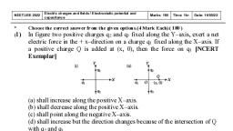
Date :-24/1/2021, , AGHMODE PHYSICS ACADEMY |, 6 ssinutes, , Exam Name :-Electrostatics, Potential and Capacitance Mark :- 120, , , , 1. In the circuit arrangement shown in figure, the value of Cy = Cz=C3=30 pF and Cz= 120 pF. If the, combination of capacitors is charged with 140V DC supply, the potential differences across the four, , , , J ¢, —F, oye, capacitors will be respectively “——, (a) 80, 40, 40 and 20 V (b) 20, 40, 40 and 80 V, (c) 35, 35, 35 and 35 V (d) 80, 20, 20 and 20 V, , 2. Three concentric conducting spherical shells carty, charges as follows : +@ on the inner shell, —2Q on the, middle shell and —5 Q on the outer shell. The charge in the inner surface of the outer shell is, (a) Zero (b) +@, (c)-2@ (a) -3Q, 3. A spherical drop of capacitance | # F is broken into eight drops of equal radius. Then, the capacitance of, , each small drop is, 1, , (a2 “ ()a*, , = (d) 8uF, , (OB uF, , 4. Taking earth to be a metallic spheres, its capacity will approximately be, (a) 64 x 108 F (b) 700 F, (c) TIL BF (d) 700 pF, , 5. Two parallel plates of area A are separated by two different dielectric as shown in figure. The net capacitance, , Ky) id, Ky 1, is, FoA oA, (a) 2a (b) @, 3e0A fine, (c) d (d) 3d, , 6.The = equivalent capacitance of the — combination shown in figure below is
Page 3 :
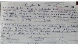
1, sc, , , , 2, 7. The electric potential at any point % ¥2 in meters is given by V = 3x? . The electric field at a point (2,0,1) is, (a) 122Vm~* (b) -6Vm™, (c)6Vm"* (d)-12Vm™*, 8. Work done in carrying a charge @’ once round the circle of radius 7 with a charge @ at the centre is, 1g _1 90", (a) 4€9 7 (b) 47% Fr, (c) Zero 20", (d) 2r, , 9. Small drops of same size are charged to V volt each. If they coalesce to form a single large drop, then its, potential will be, , (a) Vn (b) Vn, (c) ¥n¥8 (a) Vn, 10. The electric potential inside a conducting sphere, (a) Increases from centre to surface (b) Decreases from centre to surface, (c) Remains constant from centre to surface (d) Is zero al every point inside, , 11. The equivalent cage ty between points A and B in figure will be, while capacitance of each capacitor is 3, , uF. ee &, (a) 2M F (b) 4h F, (c) 7BF (a) 9B F, , 12. In the arrangement of capacitors shown in figure, cach capacitor is of 9 B F, Then the equivalent, , , , capacitance between in points A and B is, (a)9 BF (b) 18 BF, (c) 4.5 BF (d) 15 BF, , 13. The charges @ , iq and iq are placed at the vertices of an equilateral triangle of side 2. If the net, electrostatic potential energy of the system is zero, then Q is equal to, , | (b)—4, (a) 2, aa (d) Zero, (ce) 2, 14. Charges +2@ and ~Q are placed as shown is figure. The point at which electric filed intensity is zero will, ? -20, °, ? =—, be F, (a) Somewhere between —Q and +2Q (b) Somewhere on the left of -Q, (c) Somewhere on the right of #2Q (d) Somewhere on the night bisector of line joining, —Qand +2., , 15.
Page 4 :
| i °F 3F, , , , , , , , , , i 7, 2F, The effective capacitance between points 4 and B js, (a)9 (b)3, (c) o pF (dj 1, 16. :, 5 <, —_e, p————*o, ——, a, —l—, The points resembling equal potentials are, (a) Pand (b) S and @, (c)SandR (d) PandR, , 17. A metallic solid sphere is placed in a uniform electric field. The lines of force follow the paths shown in, , (b)2, (d)4, , 18. If a positively charged pendulum is oscillating in a uniform electric field as shown in figure. Its time period, , , , , , as compared to that when it was uncharged will |7>, (a) Increase (b) Decrease, (c) Not change (d) First increase and then decrease, 19, Which one of the following graphs figure shows the variation of electric potential V with distance } from, the centre of a hollow charged sphere of radius R, , , , ‘ ‘+, { aN, @ == () “——, , , , , , (©) R r (d) z ’, 20. Four capacitors are connected as shown in figure. The equivalent capacitance between A and B is, ‘A, A : tre ls, , (a) 4ftF (b) 0.25 F, , l, |
Page 5 :
1.& o.7shF (a) 133k F, , increasing the plate separation of a charged capacitor, the energy, , (a) Increases (b) Decreases, (c) Remains unchanged (d) Becomes zero, 22. A hollow metallic sphere of radius R is given a charge @ . Then, the potential at the centre is, (a) Zero 2, (b) 49" R, | = +, (c) 489° R (d) 419" 2R, , 23. In the electric field of a point charge % a certain point charges is carried from point A to B, C, D and E as, , shown in figure. The work done is ¢, (a) Least along the path AE (b) Least along the path AC, (c) Zero along any one of the paths (d) Least along AB, , 24. The given figure gives electric lines of force due to two charges hs and 92. What are the signs of the two, , "1, charges? (1994), (a) fit is positive but 92 is negative. (b) fa is negative but 92 is positive., (c) both are negative, (d) both are positive,, , 25. A square surface of side £ meter in the plane of the paper is placed in a uniform electric field E( volt fm), acting along the same plane at an angle @ with the horizontal side of the square as shown in figure. The, , E, 8, electric flux linked to the surface, in units of volt Mis (2010) (201 0), (a) BP (b) Ei? cos@, (c) EP sing (d) zero, , 26.