Notes of S.Y. EJ, EMI Chapter 3 Notes - Study Material
Page 1 :
Syllabus :, CRO : Block diagram of CRO, CRT, vertical deflection system and hori:, , time base generator, amplitude and frequency measurem, ing CRO,’ dual trace an, , frequency measurement, component testing usi, , — Function generator : Block diagram of function generator, applicatiot, , e, Function Generator, , m Analyzer, =, , oo, , izontal deflection system, need of delay leg, CRO, Lissajous patterns for phase %, d dual beam CRO., , ent using, , — DSO: Block diagram of DSO, various function and applications of DSO., , ion of function generator., , - Spectrum analyzer : Block diagram of spectrum analyzer and its applications., , , , , , , , , , , , The most versatile tool. which can be used for the, development of electronic circtiits and systems is the, Cathode Ray Oscilloscope (CRO)., , It allows the amplitude of electrical signals, whether, they are voltage, current or power, to be displayed as a, function of time., , The galvanometer and other mechanical devices have, , existed for a long time. But their major ‘limitation is, slow response., , Oscilloscopes are capable of giving a faster Tesponse to, these mechanical devices., , In 1879, William Crookes demonstrated that the, cathode rays can be deflected in a vacuum tube by, using a magnet., , The combination of focusing elements were used to, produce a narrow electron beam (called as cathode ray), aimed at fluorescent target. . y., , The combination of all these elements forme, eae, , , , known as crookes tube. It was later called as Catha, Ray Tube (CRT) or an electron beam tube., , A function generator generates different waveforms|, , adjustable frequency and voltages. ], , Function generator generates output waveforms such}, sine, square, triangular and sawtooth waves., , The frequency may be adjusted from fraction of Ha, to MHz. |, These functions (i.e. sine, square, triangular 4, sawtooth) is use to test the response of circuits, known input signal., , For example if we want to test transistor ampli, circuit the input to the circuit is given from functi, generator., The study of energy distribution of a signal 8, function of frequency is called as spectrum analysis. |, The instrument which graphically presents an enef, distribution of the Signal as a function of pane, the C.R.O. is called as spectrum analyzer., , A’ spectrum analyzer gives a calibrated ), display on its CRT, with frequency on the porizo, axis and amplitude (voltage) on the vertical axis., The spectrum analyzer used to examine the freaie™, Spectrum of radio frequency and audio signals., , Electro, , wm 3.2, , a, ua. 3.2., , ua. 3.2., , ua. 3.2., , Fig., @ 7, Gi), Gii) I, (iv) ], wv), (vi), (vii), , , , = Di, , , , , , Tech-Ne
Page 2 :
The cathode ray tube (CRT), Vertical deflection system, i) Delay line, Horizontal deflection system, (vy) Trigger circuit, (vi) Time base, , Power supply., , Fig. 3.2.1 : Block diagram of CRO., , ifference between Single trace and Dual trace, , Tt is possible to observe only one waveform Dual trace CRO we can observe two, simultaneously which are synchronized each, , There are two separate vertical input channels,, A and B. They use separate attenuator and pr, stages., , sharp cut off frequency. | Disadvantage + The two traces are not, e amplitude and the same time. So when different si, on each channel, they are |, _| simultaneously ;
Page 3 :
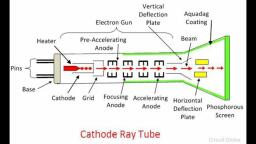
f, a2, , , , , , , , ), W-14, 4 Marks, , (b) Deflection plate assembly, (d) Glass tube (e) Base., , Fig. 3.2.2 shows the internal structure of a CRT, , Electron gun Aquadag, coating, , * ‘deflection, Pre accelerating Focusing plates Electron beam, , anode anode, ealed + 400V, , Accelerating Horizontal, , anode deflection, 2kV to B, 40kV, , " Fig. 3.2.2: Internal structure of CRT
Page 4 :
(@) Electron gun assembly, Principle, , Anelectron gun assembly con; sists of, SISIS Of g ", , - = heater, focus;, anodes and cathode. Cathode emits the electr " focusing, on beam, 'T, , electron beam is accelerated by usin, t, Sthg the, , ‘ aie accelerating, , odes, The velocity of such an electron beam es, , an alae ; ‘4M IS very high, su a g eloci ;, , When such a high velocity beam Strikes the fl :, , oa S luoresce;, , screen, a spot is created on the fluorescent Sere ee, , Screen,, , Heater and cathode, , — Cathode is used to emit the be, , ‘am of electrons. Foy, r th, purpose, the cathode is he: s, , oa ated using a heater. The, cathode heating occurs indirec ea, e indirectly. Heating increases the, temperature of cathode. The cathode is cylindrical in, , nature., , — At one end of the cathode a layer of b:, , arrium and, , , , strontium oxide is deposited. This causes electron, emission at moderate temperature. Cathode requires a, yoltage of 6.3 V and a current of 600 mA typically. For, , high efficiency it requires 6.3 V and 300 mA., , Control grid, , — The beam of electrons emitted from the cathode, pass, through a small hole in the “Control grid”., , = The control grid is cylindrical in nature. It is made from, nickel material., , — The intensity of the electron beam depends on the, number of electrons that are emitted by the cathode., , — The grid is given a negative bias. By changing ee, negative bias, the number of electrons that ue pee, through the hole in the control grid. This Bee :, the intensity of the electron beam can be contro!, this grid., , Focusing and accelerating anodes, , of a number of, , consists,, - As the electron beam © curs because the, , L is, electrons, it tends to diverge: fl, the electron repe, ostatic field is, , in order to C0, electron, , alled P), , J each other., , established between, mpensate for the, repulsion. The, reaccelerating, , same charges on, — An adjustable electr, two cylindrical anodes,, repulsive forces which caus?, two cylindrical anodes ae ., anode and accelerating ano, , , , , , , , , , i focusing anode is Placed between the, Preaccelerating anode and accelerating anode. ‘The, , focusing anode j, anode ci, ea © Is used to compensate for the repulsive, : “©. INS used to focus the electron beam., , he focusing anode is cylindri, i Sing anode is cylindrical and has a hole in the, centre, The accelerating anodes i.e, preaccelerating anode and, the accelerating anode are connected to a very high, Potential of about 2 KV to 20 KV. The focusing anode, is connected to a lower adjustable voltage of SOOV., The focusing anode is applied an adjustable voltage. By, changing this voltage, focusing of the electron beam is, , achieved. By changing the position of potentiometer,, the voltage can be changed., , Deflection plate assembly, , , , When the electron beam is accelerated by the, accelerating anodes it- passes through the deflection, plate assembly. The beam can then be positioned, , , , anywhere on the ser, , , , n., , The deflection plate assembly of the CRT consists of, the two pairs of parallel plates. These plates are called, as the vertical deflecting plate and the horizontal, deflecting plate., , An external deflection voltage is applied through an, internal adjustable gain amplifier to one of the plates of, vertical and horizontal plates, while the other plate is, , , , grounded., The external voltage is applied through external, , terminals called as the Y-input or the X- input., , A positive voltage applied to the X-input terminal will, cause the electron beam to deflect horizontally towards, the right and negative yoltage when applied to the xX, input terminal will cause the electron beam to deflect, horizontally towards the left., , Similarly, if positive voltage is applied to the ‘Y-input, terminal, it will cause the electron beam 0 oes, vertically upwards, while negative voltage applied to, the Y-input will cause the beam to deflect vertically, downwards. Son, , The amount of vertical or horizontal deflection 1S, directly proportional to the applied a pear, The horizontal deflection ) poe ltage applied, proportional to the horizontal def a as, to the X-input say Vr 8° ie
Page 5 :
Phase, inverter, , f the signal to appropriate level, it, ifier. Fig. 3.2.3 shows the block, , a a number of stages, or gains which is, , Driver Output, amplifier amplifier, , The FET source follower input stage is folloy, BJT emitter follower. J, , This is done in order to match the m, of the FET amplifier with low input, phase inverter., , Two antiphase output signals, amplifier, in order, , output... i, , The |
 Learn better on this topic