Notes of Final Year 7th Sem, Process Dynamic & Control PDC unit 3&4.lecture 5.pptx - Study Material
Page 1 :
Process Dynamics and Control, Subject Code:7CH03, Department of Chemical Engineering, Anuradha Engineering College, , Chikhli, Friday, August 21, 2015, 1, Prepared by M.A.Quazi
Page 2 :
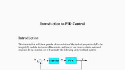
Previous Lecture 4, Contents:, Controllers, Advantage and disadvantage of Pneumatic and Electronic Controllers, Controller Actions, Electronic Circuit Implementation, Electronic Controller Actions, Proportional controller or P controller, Proportional Derivative controller or PD controller, Proportional Integral controller or PI controller, Proportional Integral Derivative controller or PID controller, Friday, August 21, 2015, 2, Prepared by M.A.Quazi
Page 3 :
Lecture 5, Contents: , Pneumatic Proportional controller or P controller, , Pneumatic Proportional derivative controller or PD controller, , Pneumatic Proportional Integral controller or PI controller, , Pneumatic Proportional integral derivative controller or PID controller, , Problem, Friday, August 21, 2015, 3, Prepared by M.A.Quazi
Page 4 :
Objectives, To understand the Mechanism of P and PD controllers ., Friday, August 21, 2015, 4, Prepared by M.A.Quazi
Page 5 :
Pneumatic Proportional Controller, Schematic of displacement type flapper-nozzle pneumatic controller
Page 6 :
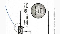
Mechanism & Working, The figure shows schematic of flapper-nozzle type proportional controller, It consist of flapper, one end of which is connected to feedback bellow and other end is diversified and connected to set point bellows and measured variable bellows., The feedback bellows is connected to the nozzle assembly, The air from the compressor enters into the nozzle assembly, This air is simultaneously flows , - through the nozzle, - towards the pneumatic control valve, - towards the feedback bellows
Page 7 :
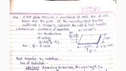
The error is produced because of the difference in the magnitude of the measured variable and set point., This error signal acts on the flapper which moves towards right covering the nozzle. , As a consequence the output pressure towards the control valve increases and thereby adjust the stem of the control valve., the enhancement of the nozzle back pressure acts against the area of feedback bellows, The connecting rod attached to the feedback bellows repositions the flapper moving away from the nozzle., In this way the pneumatic proportional controller works, Mechanism & Working (Part 2)
Page 8 :
Pneumatic Controller Actions, Friday, August 21, 2015, Prepared by M.A.Quazi, 8, Proportional Controller: , The relationship between input to proportional controller and its output is given by,, , That is,, , Where, KC is called as Controller gain. Taking Laplace transform and rearranging, we get.
Page 9 :
Pneumatic PD Controller, Schematic of displacement type flapper-nozzle pneumatic controller, R, C, Derivative time τD = RC
Page 10 :
Pneumatic PD Controller Action, Friday, August 21, 2015, Prepared by M.A.Quazi, 10, The output of a proportional derivative controller is proportional not only to error but also to time derivative of error because of addition of resistance in feedback line. That is,, and, , That is,, , Taking Laplace transforms and rearranging we get,, Where τD = RC
Page 11 :
Pneumatic PI Controller, Friday, August 21, 2015, Prepared by M.A.Quazi, 11, Schematic of displacement type flapper-nozzle pneumatic controller., Negative Feedback, Bellows, Positive Feedback, Bellows, R2, C2, C1, Integral time τI =R2C2, =1/reset rate
Page 12 :
Pneumatic PI Controller Action, Friday, August 21, 2015, Prepared by M.A.Quazi, 12, The output of a proportional integral controller is proportional not only to error but also to time integral of error. That is,, and, , That is,, , Taking Laplace transforms and rearranging we get,
Page 14 :
Pneumatic PID Controller Action, Friday, August 21, 2015, Prepared by M.A.Quazi, 14, The output of a proportional integral derivative controller is proportional not only to error but also to time integral of error and also to time derivative of the error. That is,, , and, , That is,, , Taking Laplace transforms and rearranging we get,
Page 15 :
Problem 1, Friday, August 21, 2015, Prepared by M.A.Quazi, 15, A unit step change is given to a PI controller. If the proportional sensitivity or gain Kc is 4, the Reset rate is 0.5. Obtain the response of the PI controller., Solution: The response is nothing but the graph of output {P(t)} verses time{t}, So we have to obtain different values of {P(t)} with respect to ‘t’, For PI controller the output is given as,, , , , Given: Kc = 4 and Reset rate 0.5. Therefore τI = 1/0.5= 2
Page 16 :
Problem 1 (Slide 2), Friday, August 21, 2015, Prepared by M.A.Quazi, 16, The error is given unit step change, therefore, , e(t) = 1, Now, put all the values in equation (1) and calculate P(t) for different values of ‘t’,, , , Now plot a graph between P(t) vs t
Page 17 :
Assignment, Friday, August 21, 2015, Prepared by M.A.Quazi, 17, In a PID controller the error is increased linearly at the rate of 5°C/min. The proportional sensitivity of the PID controller is 4, the reset rate is 1 and the derivative time τD is 0.5. Obtain the response of the controller., , A step change of magnitude 4 is introduced into a PI controller. If the value of Kc is 6 and reset rate is 0.5. Plot the response of the controller., , In a PD controller if the error is increased at the rate of 6C/min. The proportional sensitivity or gain Kc is 4 and derivative time is 1. Plot the response of the controller
Page 18 :
Friday, August 21, 2015, Prepared by M.A.Quazi, 18, Discussion
 Learn better on this topic