Notes of MOS 3rd Sem Mining GEC, MOS bending stress, bending equation.pdf - Study Material
Page 1 :
Chapter, , Bending Stresses, in Beams, , 5, 5.1. Theory of simple bending, (Bending equation)., 5.2. Position of neutral axis., 5.3. Section modulus., , 5.4. Practical application of, , bending equation., 5.5. Beam of heterogeneous, materials (Flitched beam)., , 5.6. Beams of unifom, strength., 5.7. Bimetallic strip., 5.8. Reinforced cement, , concrete (R.C.C.). Typical, , Examples for competitive, examinations)-, , OF SIMPLE BENDING (BEND-, , 5.1. THEORY, , ING EQUATION), When, , bending, , a, , beam is loaded it is bent and, , moments., , subjected to, Consequently, longitudinal or bending, , induced in cross-section. In order to determine, to establish, the practical utility of any beam, it is very necessary, radius of curvature to which the, a relationship between the, stress and its, beam bends, the bending moment, the bending, these, connects, dimensions. The equation which, stresses are, , cross-sectional, , quantities is, , known, , Assumptions, ., , 2., 3., , the "bending equation"., in "Theory of bending', , as, , The material of the beam is perfectly homogeneous throughout., to the strain, The stress induced is proportional, exceeds the elastic limit., and at no place the stress, of elasticity (E) is same,, The value of modulus, beam under compression or, for the fibres of the, under tension., , 4., , The, , transverse, , section of the bcam, which is plane, remains plane after bending., , before bending,, , Highlights-Objective, Type QuestionsUnsolved Examples.
Page 2 :
262, , Strength of Materials, 5., , There is, , no, , resultant, , pull or push on the cross-section of, , the beam., , 6. The loads are applied in the plane of bending., 7. The transverse section of the beam is symmetrical about a line passing through the, of gravity in the plane of bending., , 8, , The radius of curvature of the beam before bending Is very large in comparison, transverse dimensions., , As a result of a bending moment or couple, a length of beam will take up a curvedshane, a very short length may be treated as a part of the arc of a circle. It follows that at the outer rati, material will be in tension, and at the inner radii in, compression, and at, some radius there will be, no stress. This layer of, the meterial is the neutral, , layer or neutral axis., Fig. 5.1 shows a, longitudinal section of a, , beam; the neutral layer, , R, , (axis) N.A. being bent to, form an arc of a circle of, radius R. The neutral, layer is then, before, , bending, the length pq,, which after bending becomes pq, , Fig. 5.1, , Consider some layer rs at a distance y from pq, which after bending becomes r's. Let p, subtend an angle a at the centre of curvature., p'=, , Ra and 's' = (R-y) a, , MOTAUO1 2M, , Initially the parallel layers would have equal lengths, so that pq = rs and since thereisnostes, at the neutral layer, then there is no strain., , peep09 2lnorgom g, , p'q=pq, TSrs, , Now the strain in rs, , rs, , butrs =pq =p'q', , p, , logiliulooio, , beodtopwod qidaa, , Strain=, , e, , gnibood edi ,insmom gnibeod odh abrod, , S, , But,, and,, , p'g' = Ra, 's=(R-y) a;, , strain =, , Ra- (R, , -, , y) a, , y i enoigue, , og Rodso Ris oT, Juorlguodi euoon, , Now if the stress in rs = O and Young' s modulus is E, then, , Strain, , E, , )ioteals ho globocn to oulay odl, nod sd lo, , 21dih sdh not, , 5, , If a transverse section of the beam is now considered (Fig. 5.2), let a strip of area ôa, lie, , distance y from the neutral axis., , od aitgouse oeT9vernsdorlT, , Ihen, the normal force on this area (oa) = y o a, , d, , atbin1g01bnsd ovolsd
Page 3 :
Chapter:, , Bending Stresses in Beams, , 5, , 263, , Now the moment of this force about the neutral axis is, , y oaxy, This is the resistin;, , or, , R, , a, , moment of the material, caused by the, , stressproduced, and the total resisting moment is, , N, , R, is, the, S.oa, second moment of, , d, , area, , axis,NA, Resisting moment M =xi, But, , since the, , IILITTILLITLILITA, , da, , about the neutral, , resisting moment balances the, , moment,, , applied bending, , Fig. 5.2, , M x I or, R, , E, But,, , R, , M, , E, R, , where,, , M, , =, , I=, E, , =, , R, , =, , Moment of resistance., Moment of inertia of the, , equation, , 5.2. POSITION, for, , OF, , The force, , of curvature of N.A., and, Bending stress., , is known, , as, , Now, , "Bending equation'., , NEUTRAL AXIS, of, , a, , acting on a, , small, , beam, , area, , dca, , (Fig. 5.2),, , at a, , there will be, , distance, , 'y, , no, , resultant force, , from the neutral axis is, , E, , F=a, , For, , the, , equilibrium., , or, the total, , neutral axis (N.A.),, , Radius, , Consider the cross-section, , condition of, , section about, , Young's modulus of elasticity., , =, The above, , (5.2), , on, , the section, , given by:, , =r, R, , force normal, , to the section., , zero resultant force, , 2y da, , is the moment, , y du, , =0., , of the sectional, , area about the neutral axis, and since, this, e n t is zero, the axis, must pass through the centre of area., ience the neutral axis or neutral, the centre, , layer. passes through, , 5.3. SECTION MODULUS, Referring to the bending equation,, , Owe have, , of area.
Page 4 :
264, , Strength of Materialsnsd, G-, , M, , M, , or, , Z, (5.3), , where,, , Z=Section modulus =Ily, A, , The section modulus is usually quoted for all, standard sections and practically is of greater use tha, , the second moment ofarea (.e., M.0.1)., , The strength ofthe beam section depends mainly, on the section modulus., The section modulii of rectangular and circular sec-, , tions are calculated below:, () Rectangular section:, , Fig. 5.3, , Fig. 5.3 shows a rectangular section of width b and depth d. Let the horizontal centroidalatis, be neutral axis., , Moment of inertia about the neutral axis, Section modulus, Z =, , Distance of the most distant point of the section from the neutralayis, , bd and, YE, I =*, , But,, , 12, , bd'12 bd, dl2, , (Moment of resistance,, , M, , =, , oZ, , =, , ax, , 6, , bd), , Colorado river bridge, , ilnpo ovode odlf
Page 6 :
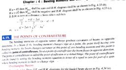
266, , 5.4, , Strength, , of, , Materialsbne, , PRACTICAL APPLICATION, , 1ofe0, OF BENDING, , EQUATIONlo, , o) 1915, , The bending equation, , 1S, , based upon the theory of pure, bending and the, assumptions taken thereupon, which require, that the beam should be subjected to constant, bending moments unaccompanied by shearing, forces, but in actual practice the bending, moment varies from point to point, along the, length of the beam and also, the bending, moment is accompanied, by a shearing force., However, in a large number of practical cases,, the bending moment is maximum when the, shear force changes sign, i.e. crosses the zero, , N, , shearing force line. In this way the requirements, to, , simple bending, , -150 mm, , approximately satisfied, at the point of maximum, bending moment and, are, , Fig. 5.7lo, 2.git o11o16, , therefore, it seems justifiable to apply the, bending equation at that point only., , Example 5.1. A 250 mm (depth), , x, , 150 mm, , bending moment of 750 kNm. Determine:, (i), , o.C), , (width) rectangular beam is subjected to maximm, , The maximum stress in the beam., , (i) 1f the value of E for the beam material is 200 GN/m, find out the radius of, curvature, that portion of the beam where the bending is maximum., aulubom noios2 fer, (iil) The value of the longitudinal stres at a distance of 65 mm from the top, surface of the, beam., Solution. Refer to Fig. 5.7., Width of the beam,, , b =150 mm =0.15 m, , Depth of the beam,, , d, , 250 mm = 0.25 m, , Maximum bending moment, M= 750 kNm, , Young's modulus, , of, , elasticity,, , E, , =, , 200 GNm°., , () Maximum stress in the beam:, , bd, , Moment of inertia,, , I, , Distance of neutral axis, , 12, from the, , (N.A.), , ode holb sdh to sinonm lo nodol, , 0.15 x 0.253 =, , =0.125, Using the relation,, , M, , 0.0001953 m*, , 12, top surface of the beam,iobe, , m, , O we get, M-y, , 750 x 10'x 0.125, 0.0001953, , = 4.8 x 10³ N/m or 480 MN/m2, , Hence, the maximum, , stress in, , the beam, , =, , 480 MN/m, , (Ans.)
Page 7 :
Chapter : 5: Bending Stresses in Beams, , 267, , of curvature, R:, (t) Radius, E, , relation, _, Usingthe, R, , R, , we get, , 200x 10x 0.0001953, 750x 10, , EI, , 52.08 m (Ans.), , M, Ci) Longitudinal stress at a distance of 65 mm from top surface of the beam, o,:, , Usingthe relation, M =O_O1 we get, y, , M.y, 750 x 10x (60 x 10), , x 10° MN/m* (: y, = 125 - 65 = 60 mm), , 0.0001953, 230.4 MN/m, , (Ans.), , Example 5.2. A symmetrical section 200 mm deep has a momentofinertia of 2.26 x 10⁵, , abou, , its neutral axis. Determine the longest span over which. when simply supported. the beam would carry a, , uniformly distributed load of 4 kN/h1 run without the stress due to bending exceeding 125 MNn?, Solution., Depth of the symmetrical section., , d= 200 mm, , Moment of inertia about neutral axis. / = 2.26 x 10 m, Uniformly distributed load., =4KN/m run, =, 125 MN/m., Maximum bending stress., Longest span, I:, , M, , Using the relation, , M, , .we have, 125, , x, , 10°x 2.26, , x, , 10, , 0.2/2, = 28.25 x 10³ Nm = 28.25 kNm, , In tall buildings such, , as, , WTC, , towers, , steel beams, , are, , used to hold concrete structure.
Page 8 :
268, , Strength of Materials, AISo the maximum bending moment due to uniformly distributed load is, , 4X=0.51 kNm;0.5 =28.25, I, , From which., , 7.516 m (Ans.), span 8, , to carry, , brick., 5.3. Determine the dimensions ofjoist of a timberfor, 200 mmExample, thick and 5 m high, if the density of brick work is 1850 kg/m' and the marimum permic, stress, , is limited, , to, , depth of joist is, , 7.5 MN/m'. Given that the, , m, , a, , wice the width., , sible, , Solution., l=8 m, , Length of span,, , 200 mm or 0.2 m, , Thickness of brick wall, , Height of the wall, , 5, , m, , Maximum permissible stress, , = 7.5 MN/m, , Density of brick work, , = 1850 kg/m', , Width of the joist, b:, , Depth of the joist, d:, Total weight of the wall, , W= Length of span x thickness of wall x height of wall, x density of brick work perm, = 8 x 0.2 x5x (1850 x 9.81), = 145188 N or 0.145 MN (say), WI, , 0.145 x 8, =, , Maximum B.M., M=, , Moment of resistance, , O, , Ox, , 0.145 MNm, , bd'/12, , =, , _, , dl2, b d 7 . 5x, , or, , M, , =, , 2, , MNm., , = OX -, , 6, where, b and d are in metres., Equating moment of resistance to B.M.. we get, , 7.5 x bd-, , = 0.145, , 6, , ba?=0.145x 6, Or,, , = 0.116, , 7.5, , bx (26) = 0.116, , or,, , (:'d=2, , (0.116 B, , From which,, , 4, b = 0.307 m or 307 mm, , (Ans.), , d 2b = 2 x 307 614 mm (Ans.), and,, Example 5.4. A beam consists of a symmetrical rolled steeljoist. The beam is simply suppor, , at ius ends and carries a point load at the centre of the span. If the maximum stress due to be, is 140 MPa.find the ratio ofthe depth ofthe beam section to span in order that the central deflece, may not exceed, , ofthe spa1., , Take, E = 200 GPa., , (AMIE Summer, 200
Page 9 :
Chapter, , :5:, , Bending Stresses in Beams, , G= 140 MPa; 8l =, , Solution. Given:, , 480 o the span (); E =200 GPa., , Ans, , d, W-Point load at the centre of the, , Let,, , ol, , span, and, Central deflection due to, the load W., , =, , W3, , Then,, , 48 EI, , 480, , hen outside dianete, , 480, ding ooment towhi ElWx, =, 10W?, CCO481, 200x 10xI=10 WP, , Or,, , or,, , 269, , ow, , 22omlaib eW, nir olisw lo 1otsrnsib, , Ce00C8-2, , abiauO, , lecio.bT 10WI, , From the bending, , ism to, , 200 x 10, , equation,, , we can, , 1Oto toomsib abienl, , lenoitose-coro wol, , ses, , write, , here, M=, , Nowasing the relaW, 140x 10, 10W2, , 200 x 10, WI, , 200 x, , 102x140x 10, , 10W, , 200x 10 2x140 x 10°, , Or,, , 4x 101, , d, 2x 140 x 10°x 4x 10, , Of,, on, , = 0.056, , 200 x 10, , (Ans.), , Example 5.5. A floor has to carry a load of 12 kN per square metre. The, floor is supported, rectangular joists each 300 mm x 100 mm and 5 long. Calculate the distance, m, , centre to, , centre) at which joists should be placed so that the maximum, , exceed 8 MN/?, , stress in, , apart (from the, the joists should not, , Solution. Moment of inertia of each joist,, 0.1 (0.3), , 2.25, 12, which each joist is subjected,, =, , 12, , Maximum B.M. (M, , to, , M, , =, , O_8x 2.25 x 104, 0.30/2, , =, , x, , 10 m, , 0.012 MNm= 12kNm, , ..), , Let x be the spacing, in metres, of the joists from centre to centre. Each joist will share half of, on either side. The, length of each joist is 5 m. Therefore, , the load of the floor between two floor joists, , the total load on each joist (if the spacing between two joists is x from centre to centre) will be, =, , 12 xxx 5, WI, , . Maximum B.M., , =, , 60 xkN, , 60xX KNm, 8, , .i)
Page 10 :
LI0 m Strength of Materialshne, , :19fgsid, , bnted, , From eqns. (i) and (i), we get, , 60x x 5, , 12, , or,, , which,, , toinloe, , 8, , X=, , 12X8 _ 0.32 m or 320 mm (Ans.), 60x5, , Example 5.6. A, , cast, , iron, , water main, , water and is, , wall thickness runs full of, iron is 7200, metal if density of cast, Solution. Refer Fig. 5.8, , area, , metres, , supported at, , kg/m?, , and that, , Inside diameter of C.I. water main,, Wall thickness,, Outside diameter of water main,, Now crosS-sectional, , 12, , inside, , its ends. Calculate the, , of water is 1000 kg/m., , d= 500, , t, , long, of S00 mm, , mm, , = 0.5, , diameter andd 25 mn, a, , maximum stres, stress, , in the, , m, , 25 mm =0.025 m, , =Lx01x 00S, D =d+ 21 = 500+2 x 25 550=0.55 m, , J0, , = TU4 (0.552 - 0.5 ) =0.04123 m2, , of main, , 10, , Weight of water main per metre length, = 0.04123 x Ix 7200 x 9.81 N=2912.16N, , Cast-iron, , heightofw, , water main, , Y of bick wot gpern, , wOr, x00S, , Ma, , Water, , 10, 10, , w, , 25 mm, , 25 mmutok ow, , 500 mm, Fig. 5.8, , sd, , Weight of water in one metre long main, = (Tt/4) x (0.5)2 x 1 x 1000x 9.81 N =1926.19 N, Total weight of pipe (per metre length) when full of water, , 2912.16 + 1926.19 =4838.35 N, oriy o1 ( ) . M . a u i s, , Bending moment,, , Mw, , 4838.35x12, , Nm = 87090.3 Nm, , u0-8, Moment of inertia,, , 1= (TW64) [O.55) - (0.5)] = 1.42384 x 10³ m, D, , Using the relation,, , ,, , 0., we get, , 0.275 m, , oll ovetgtowisdaoolloifio
Page 11 :
Chapter : 5 Bending Stresses in Beams, , 271, , M:y87090.3 x 0.215 10-16.82 MN/m, 1.42384 x 10, , (Ans.), , Example 5.7. A hollow circular bar having outside diameter twice the inside diameter is, used as a beam. From the bending moment diagram the, of beam, it is found that the bar is subjected, 40 kNm. If the, to a bending moment, allowable bending stress in the beam is to be limited to 100, , of, , MN/m?, find the inside diameter of the bar., Solution., Let,, Then outside diameter, , Bending moment to, , d, , =, , Inside diameter of hollow, , D, , 2ddt si mw, which the bar is, M, , siod, , noise ss sbivid, , subjected to, , =, , circular bar.O, , 40 kNm, , =, , Allowable bending stress, G 100 MN/m2, Tnside diameter of the bar, d:, 00cS, =, , 000 Moment of inertia,, , I, , =, , T/64 (D'-d'), , y, Now, , using, , the, , relation,, , M, , es, , er-poe, or,, , =, , ri64, , 15, , [(24)- d'] nd, 64, , nsioe, , =, , 2 dd, , we get,, My, , 100x 10, , 40x1000 x d, 15, 2Ttd, 64, , Vertical boring machine., , (, , 1, , MN/m2 10 N/m), =, , h Wolad 202911e oltesos b a e x
Page 12 :
272, , Strength of Materialshne8, 40, , 1hasrlo, , 1000x64, , x, , Or,, , mMMSB.aol-0d= 15Tx 100 x 10°, , Or,, , hies s t soi, , sthd, , 0.0816, , =, , or, , m, , 81.6, 50, , 0.0005432, nmm, mm, , (Ans.)ot A..cplg, , each, , a r e connected, , toform a T.., , Example 5.8. Two wooden planks 150, neutral axis, inducine, around the horizontal, tensi, a beam. Ifa moment of 3.4 kNm is applied, cross-section., Also calculn, the, of, of, extreme, fibres, the, ulate, below the neutral axis, find the stresses at, mmx, , total tensile force on the cross-section., Solution. Given: Moment, , =, , 3.4 kNm, , Divide the section into rectangles, , as, , 3.4, , =, , 103 Nm, , x, , shown in the, , 1919m8ib sbialuo m9T, , Fig. 5.9., , ay (mm'), , Centroidal distance from, the bottom face, y (mm), , Component, , Area 'a' (mm), , Rectangle (1), , 150x 50 = 7500, , 75baodLodlbia, , Rectangle (2), , 150 x 50 = 7500, , 75, , STOn, , 2a = 15000, Distance, , of the neutral, , 2319gits 1312500, 562500, , ay 187500, , axis XX from the bottom face,, 1875000, , = 1 2 5 mm, , F=2ay, , 15000, , Ea, , 150x 50+150, , Ixx, , noislorrih gaieu wo, x 50 x (175 - 125), , 12, , 50x 1503, , oo1 xO+ 1 2, , +150 x 50(125 - 75, , = (1562500+ 18750000) + (14062500 + 18750000), 5312.5, Extreme fibre stresses:, , x, , 10, , mmt or 5312.5, , x, , 10-8 m, , Refer to fig. 5.10., , Distance of c. g. from the upper extreme fibre,, y. = 200, , 125, , 75 mm, and y, = 125 mm, , Now using the relation,, 150 mmnM, , with usual notations, we get, , M xy, , Tensile, , stress,, M, O,=, , xy_ 3.4 x 10 x (125, , x, , 10), , I, , 5312.5 x 10-8, 8 x 10° N/m or 8 MN/m2 (Ans.), , Compression stress,, O, , =, , M xye_3.4 x 10x (75 x 10), 50 mm, , 5312.5 x 10-*, =, , 4.8, , x, , 10 N/m, , or, , 4.8 MN/m, , Total tensile force on the cross-section:, , (Ans.), Fig. 5.9, , We know that the section is subjected to compressive stresses above the xr-axis, axis, and tensile stresses below it as shown in Fig. 5.10o, , i.e,neul, nee
Page 13 :
Chapter:5 Bending Stresses in Beams, , 273, , 150 mm, , Neutral axis, , X, , 50 mm, Fig. 5.10, Area in tension, , =, , Total tensile force, , =, , 125, , x, , 50, , x, , 106, , Average tensile, , =, , 6.25, , x, , 10 m2, , stress x area in, , tension, , 8x 10+0, 2, , Example, , x6.25 x103, , 25000 N or 25 kN (Ans.), 5.9. A beam simply supported at ends and, , having cross-section as shown in Fig.5.11, whole of its span. If the beam is 8 m, long, find the U.D.L. if maximum, permissible bending stress in tension is limited to 30 MN/m* and in compression to 45 MN/m*., What, are the actual maximum, bending stresses set up in the section?, is loaded with, , a, , U.D.L.,, , over, , 100 mm-, , 3 0 mm, , 120 mm, , Fig. 5,11
Page 14 :
274, , Strength of Materials, Solution. Refer to Fig. 5.12., 100 mmY, , Top flange, , 30 mm, Web, Neutral axis, , X, , G, , Bottom flange, , Y, , 120 mm, Fig. 5.12, , The following table gives the calculations for location of horizontal neutral axis:, , Component, , Area 'a' (mun), , Centroidal distance from, , ay (mn'), , bottom edge, 'y' (mm), 30, , Top flange, , 100 x 30 =3000, , 200, , Web, Bottom flange, , 120 x 30 = 3600, , 50+120/2 110 mm, , Total, , = 185 m m, , 555000, =, , 120 x 50 = 6000, , 50/2, , 396000, , 25 mm, , (a) = 12600, , 150000, (, , Distance of the centroidal axis XX from the bottom, 2ay 1101000, , ay) = 1101000, , edge,, , = 87.38 mm, , Za, , 1op, , 12600, , fange tweb potom flange, 100 x30, 12, , +100 x30(112.62 15|, , 30x 120, 12, , 120, , x 503, 12, , +30x120x(110 87.38), 120 x 50x (87.38, , (225000 + 28588993) + 4320000, +1841992) +(1250000 +23347586), 28813993+ 6161992 + 24597586, =, , =, , 5957, , x, , 10 mm* or 5957 x 10*m, , 25)
Page 15 :
Chapter: 5: Bending Stresses in Beams, , 275, , 18th Century boring machine., , Maximum bending moment,, , M =W wx82, 8, , 8, , 8w, , (where, w = uniformly distributed load), , For tension side of the I-section, , M, M, , =, , Ix, , O= 3957 x 10*x, , 30, , >x, , 106, , 87.38 x 10, 20452 Nm =20.452 kNm, , For compression side of the I-section, M, , ., , Moment of resistance, , = * 5957x10-8x 45x 10, 112.62 x 10, e, = 23802.6 Nm 23.8026 kNm, , M = 20.452 kNm (i.e. minimum of the above two values), 8w = 20.452, , 20.452 2.556 kN/m, 8, , or, , Actual maximum, , stress, , (Ans.), , in the top-most fibres of the beam, M, =, , 20.452 x 10 x 112.62 x 10, 5957 x 10*, , 38.6 x 10 N/m = 38.6 MN/m2 (compressive), , (Ans.)
Page 16 :
276, , Strength, , of Materials, , 1ofqmlo, , Actual maximum stress in the bottom-most fibres of the beam, 30 MN/m2 (tensile) (Ans.), Example 5.10. Fig. 5.13 shows a cost iron bracket of crosS-section of 1-form. Find:, =, , ), , Position, , of the neutral axis and the, , moment, , axis., , (i), , of inertia of the section about the, , neuret, , Determine the maximum bending moment that should be, imposed on this section if tha, tensile stress in the top flange is not to exceed 40 MN/m', What is then, the value of he, compressive stress in the bottom flange?, , Solution. Refer Fig. 5.13 and 5.14., Cast iron, Bracket, , Load, 200 mmn-, , 40 mm, , 40mm, , 40 mm, -120 mm-, , Fig. 5.13, , houdiib virenoiio ee, , -200 mm-, , Top flange, , o,40 MN/m, 40 mm, , Web, , Neutral axis, 4 0 mm, , Bottom flange, 40 mm, , -120 mm, Fig. 5.14
Page 17 :
Chapter: 5 : Bending Stresses in Beams, , 277, , Position of the neutral axis:, , ), , The section may be split into three rectangular components. The table of calculations is, given below:, , Centroidal distance from, , Area 'a (n-), , Component, , ay (mmP), , bottom edge, 'y' (mm), , Top flange, , 200x 40 = 8000, , 260 mm, , Web, , 200x 40 =8000, , 140 mm, , Bottom flange, , 120x 40 = 4800, , 20 mm, , Total, , 2080000, 1120000, 96000, , (2a) = 20800, , Distance, , of the neutral axis, = Eay, , from the bottom, , 3296000, , Za, , Hence, , e, , and,, , (2 ay) = 32960000, , edge,, , = 158.5mm, , 20800, , (Ans.), , 158.5 mm, y, = (40 + 200 + 40) - 158.5 = 121.5 mm, , M.O.I., , Ix=?, , XxtOp flangewebbottom flange, 200 x 40, , -, , +200x, , 12, , 40 x (121.5 20), -, , 40x 200, +, , 12, , 120x 40, , ii), , =, , 83484667, , =, , 2.056, , 40, , x, , 200, , x, , (158.5 -140), , +120 x 40 x (158.5 - 20), , 29404667 +92714800, 10 mm* 2.056 x 10 m4, , x, , +, , =, , Maximum bending moment, M:, Using the relation,, , M, , ,we geet, , =x, , M, , Of,, , =, , I, , =, , 40X10°x 2.056x 10⁴, , 121.5x 10³, 67687.2 Nm =67.7 kNm (say) (Ans.), , Compressive stress in the bottom flange, o:, , Using the relation:, , M, (67.7 x 10') x (158.5 x 10), or,, , O,, , 2.056 x 10, = 52.19 x 10° N/m = 52.19 MN/m2, , (Ans.)
Page 18 :
278, , Strength, , of Materials, , Example 5.11. The horizontal beam of section shown in Fig. 5.15 is 4 m long and is gin, imply, supported at the ends. Calculate the maximum uniformly distributed load it can carry if the teni, and, , compressive, , stresses must not, , exceed 25 MN/m? and 45, , 20 mm, , MN/m, , ensile, , respectively., , 120 mm, , 2 0 mm, , gnslt mroto8, stoT, , O08OC=, , tagonsteid, , C20 mm, , A0, , CFig. 5.15, Solution. Divide the section into three, , bns, , rectangles (components) as shown in the Fig. 5.16, O45 MN/m, , e65 mm, , Neutral axis, -, , y 3 5 mm, , 20 mm, , Y, 20 mm-, , o,24.23 MN/m, , 120 mm, , 20 mm, , Fig. 5.16, The areas of the individual, components, their, their moments about the bottom, edge are tabulated, Area 'a (mm-), , Rectangle (1), , 100 x 20=2000, , Rectangle (2), , 100, , x, , 20, , =, , Rectangle (3), , 120, , x, , 20, , =, , Total, , 2000, 2400, , a, y,, , =, , 35, , 2, CC, , 50, , 100000, , 108or, , 24000, , (, , edge,, , 224000, , and y, , 100000, , -, , = 35 mm, , 6400, mm, , ay (mnt), , 50, , Distance of the neutral axis from the bottom, , =, , O, , :, , Centroidal distance from, bottom edge, 'y' (mm), , a ) = 6400, , Lay, , ugke, , rotsler rb, centroidal distances, from the bottom edge an0, , below, , Component, , -, , 100 -35, , XXrect.-1 rect-2 Trect.-3, , =, , 65, , mm, e-, , ay) = 224000
Page 19 :
Chapter: 5: Bending Stresses in Beams, , 279, , 20 x 100 +20x100x(50 35, 12, , 20x 100 +20x100x(50 35), 12, 120x 203, , 2, , =, , 12, , +120x20x (35 10, , 2116666 + 1580000, 5813332 mm, 581.33 x 10 m*, , =, , x, , =, , M, , We know that,, , S, 65, , or,, , So, the ratio of, is 1.857., , compressive, , 35, and tensile stresses, , If the beam is loaded such that, stress, (G)should not exceed 45 MN/m, thecompressive, permissible limit., the corresponding tensile stresses, (o,), according to the, above ratio, will be:, 45x, , =, , Augur (component) used, machines., , 24.23 MN/m, , 1.857, , in soil, , which is within the, permissible limit: but in case. the, beam is loaded so as to, produce tensile stress of 25 MN/m*, the, would be 25 x 1.857 =46.42 MN, which is, , boring, , corresponding compressive stress, more than the, /m, permissible limit given in the question., Hence the actual stress, produced in the beam should be 45 MN/m*, compressive and 24.23, MN/m tensile and the U.D.L. (uniformly distributed load) can be determined, from these values., Using the relation:, , M, , =* O, , ,, , we get, , M =. =, Substituting, o, = 24.23 MN/m* (and not the given value), o=45 MN/m, y, = 35 mm., Y= 65 mm., l= lyy = 581.33 x 10- m., , M ., 24.23, , x, , 10x, , (581.33 x 10) ,, Nm, , *, , 35 x 103, , or, , 4.0245 kNm, , Let w be the uniformly distributed load in kN/m run, , Mma, , wl, 8, , wx 4, 8, , bquating the maximum bending moment and the resisting moment M, we have, WX4, , 8, , = 4.0245
Page 21 :
Chapter: 5 Bending Stresses in Beams, , 281, , The areas of the individual components, their centroidal distances from the bottom edge and, heir moments about the bottom edge are tabulated below:, , Area 'a' (cm*), , Component, , 16 x 2= 32, , Rectangle (1), Rectangle (2) and (3), , 2x 15x, , Rectangle (4) and (5), , 2x9x4= 72, , Total, , y, , 2ay1474, , =, , La, y,= 9 cm, , 11.5, , 690, , 2, , 144, , = 164, , neutral axis from the bottom, , ay (cm3), 640, , 20, , 2 =60, , a, , Distance of the, , and,, , Centroidal distance from, bottom edge, 'y' (cm), , a y = 1474, , edge,, , = 8.90 say 9 cm, , 164, , y=12cm, , XXTect. -1*rect. -(2 &3) rect. -(4 &5), , -, , A+16x 2x (12 -1+2x 2x153 +2x 15 x (11.5 - 9), 12, , 9x43, 12+9x4x(922), , 3883 + 2x 750 + 2 x 1812, 9007 cmt or 9007x 10-5 m, , 212, , =, , )Bending moment M:, Using the relation,, , M, , M, , - , we get, =xI, , 30x 10°x9007x 10, , =, , 9x 10⁻², , 30023 Nm or 30 kNm (say) (Ans.), (i) Stress at the top edge o, Using the relation,, , => = , we get, , o=, , x, , ye, , (30x 10*) x 12 x 10, 9007.6 x 108, = 40 x 10 N/mor 40 MN/m2 (Ans.), , Automobile carburettor.
Page 22 :
282, , Strength of Materialsmo, , vofqsilo, , bas s Example 5.13. A steel stanchion is built of a rolled steel joist of I section 45 cm x, , united by 1.5 cm thick and 30 cm wide platesfastened on each flange. The length of the, the estanchi, is 5 m and is freely supported at both ends. For the I section: Ix = 35060 cm* Find, , (), (ii), , Moment, , of inertia of the enlarged section about XX-axis., , Greatest central point load the beam will carry if the bending stress is not toes., , 120 MN/m?, (iii), , Minimum length of the 30 cm x 1.5 cm plates., , exS, , Solution. Fig. 5.19 shows the stanchion., , (E) bas (S) slgnn, () bns () olona, , AT) M,O.I. of enlarged section:, , etoT, , Moment of inertia of the enlarged = Moment of inertia of I-section about XXati, section about XX-axis, , moment, , Ix=35060+2X, 83727.5, , cm, , plates about XX axi, , +30x 1.5x, , 35060 +2 (8.437, =, , of inertia of the, , b, , +24325.313), , (Ans.), , Sxot, , 30cm, Plate, , 1.5 cm, , 2 0 cm1-section, , isloy sd) gnieU, , Neutral axis, , oiuolor olf gnted, 1.5 cm, Plate, 30 cm, , Fig. 5.19, , i ) Greatest central point load W:, , Xoix0), , We know that,, Maximum B.M., , W=1.25, , w, , 0
Page 23 :
283, , Chapter: 5 Bending Stresses in Beams, But moment of resistance,, , =x1 120x10, , M, , 24 x 102, 418637.5, , 1.25 W, W, , or., , 418637.5, , =, , 334910N, , =, , 1.25, , (, , 83727.5x, , x, , 10=418637.5 Nm, , 334.91 kN, , =, , (Ans.), , Minimum length of the plates:, Suppose the cover plates are absent for a distance of x metres from each support. Then at, , these points the bending moment must not exceed moment of resistance of I section alone i.e., , x, , =120 x 10x35060 x 10-, , = 175300 Nm, , 24 x 102, , Bending moment at x, , metres from each, , support, , W, , XX=175300 or 354910_17, 175300, 2, , from which, , X= 1.05 m., , Hence leaving 1.05, plates should be provided., , metre from, , each, , support, for, , (Ans.), , the middle 5- 2.1, , =, , 2.9 metres, the, , cover, , Example 5.14. A simply supported beam and its cross-section are as shown in Fig. 5.20., 20 kN as shown. Its self-weight is 7 kN/m. Calculate the, maximum, , The beam carries a load W, normal stress at 1-1., , =, , W, , 20 kN, 7 kN/m, Y, , S cm o hole, , 10 cm, -, , 1.2 m, , -1.2, , m. 1.2, , 17.1 cm, , m., , y12.9 cm, A, , B, , L, , Y |L, K20cm>, , Fig.5.20, Solution. To determine reaction at the supports taking moments about A, we get, , Rx 3.6 =20 x, , 2.4+7x 3.6, , 93.36, , R 3.6, But,, , RA, , +, , R,, , =, , 20 +7, , x, , 3.6/2 =93.36, , = 25.93kN, x, , 3.6, , =45.2, , kN, , R=19.27kN, Bending moment at 1-1,, , M =25.93, , x, , 2.4 2 0, , x, , 1.2 7, , x, , 2.4, , x, , 2.4/2, , 18.072 kNm, , Refer to cross-section of the beam. The areas of the individual components, their centroidal, , distances from the bottom edge (LL) and their moments about the bottoms edge are tabulated below:
 Learn better on this topic