Notes of S3_ADC, Analog Devices & Circuits Presentation1-ADC-FINAL.pptx - Study Material
Page 2 :
Course overview, ANALOG DEVICES AND CIRCUITS, (ANALOG ELECTRONICS), , ANALOG DEVICES –DIODES, TRANSISTORS, OPAMPS, THEIR APPLICATIONS ETC, , CIRCUITS- RECTIFIERS, FILTERS, AMPLIFIERS, OSCILLATORS ETC, 2
Page 3 :
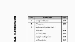
MODULE-1 OVERVIEW, MODULE1 –RECTIFIERS AND WAVE SHAPING CIRCUITS, COURSE OUTCOME, , , , , CONTENTS, ACTIVE DEVICES/PASSIVE DEVICES, RECTIFIERS, FILTERS, CLAMPER CIRCUITS, CLIPPER CIRCUITS, 3
Page 4 :
ACTIVE/PASSIVE COMPONENTS, Electronic components can be divided into two, Active Components, Passive Components, , Active components, Can amplify or process an electrical signal, Ex: diodes, transistors, , Passive components, Not capable of amplifying or processing an electrical signal, Ex: Resistors, inductors, capacitors, 4
Page 5 :
rectifiers, Rectifier, Converts AC to DC, , , , , Rectifiers are of 2 types, Half Wave Rectifier, Full Wave Rectifier, , A Diode can work as a rectifier, Diode conduct current in one direction only., Hence can be used as rectifier, 5
Page 6 :
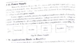
Requirement of rectifier, Rectifiers are part of DC Power supply, DC Power Supply, All electronic circuits requires constant dc voltage for their operation, Converts domestic ac supply to dc supply, Consists of Rectifier, Filter and Voltage Regulator, Fig : Basic block diagram of DC power supply, 6
Page 7 :
Requirement of rectifier, 7, RECTIFIER: , Rectifier circuit employs one or more diodes to convert ac voltage into pulsating dc voltage, FILTER: , Filter circuit removes the fluctuations or ripples present in the output voltage supplied by rectifier, VOLTAGE REGULATOR: , Voltage regulator keep the terminal voltage of dc supply constant
Page 8 :
Requirement of rectifier, 8
Page 9 :
Diode -review, Symbol of Diode, , Diode has 2 terminals, Anode, Cathode, Diode can be connected in circuit in 2 ways, Forward biased, If Anode of diode is positive with respect to Cathode , diode is forward biased, Diode conduct, Reverse biased , If Anode of diode is negative with respect to Cathode, diode is reverse biased., Diode does not conduct, 9
Page 10 :
Diode review, DIODE FORWARD BIASED, DIODE CONDUCTS- IT ACTS AS A CLOSED SWITCH, DIODE REVERSE BIASED, DIODE DOES NOT CONDUCT- IT ACTS AS A OPEN SWITCH, 10
Page 11 :
Diode review-diode in circuit, 11
Page 12 :
Diode as rectifier, 12, Diode allows to current to pass in one direction only, This property is used in rectifier circuit, If AC supply is given to Diode, Diode passes only positive half cycle.
Page 13 :
Rectifier circuits, 2 Types of Rectifier circuits, Half Wave Rectifier, Full Wave Rectifier, 13
Page 14 :
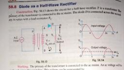
Half wave rectifier, Circuit consists of a diode in series with load resistor, Transformer used for to step up/ step down source voltage, 14
Page 15 :
Working of hw rectifier, During Positive Half cycle of AC input Voltage, Diode is forward biased, Diode conducts , Diode acts as short circuit, Voltage is produced across Load resistor, RL, 15, +, -
Page 16 :
Working of hw rectifier, During Negative Half cycle of AC input Voltage, Diode is reverse biased, Diode does not conduct, No current flow and voltage across RL, 16, +, -
Page 17 :
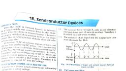
Output of hw rectifier, Output waveforms, Only positive half cycle appears across RL, Negative Half cycle is suppressed, Output is not a steady dc , it is pulsating dc wave, Only positive half cycle is used, hence called Half wave rectifier, 17
Page 19 :
Average value of dc output, 19
Page 21 :
Performance parameters of rectifiers, Rectification Efficiency, Ripple Factor, Peak Inverse Voltage, Transformer Utilization Factor, , Performance parameters are important for the design of rectifier circuits, 21
Page 22 :
Performance parameters of half wave rectifier, Ripple Factor, Ripple factor is a measure of purity of dc output of a rectifier, Defined as the ratio of ac component of the output wave to the dc component in the wave, Ripple factor = , Rms value of AC component of output voltage/Value of DC component of Output voltage, Output of rectifier consists of 2 components, DC Component, AC Component(Ripple), AC Component is undesirable., causes pulsations in rectifier output, Ripple factor=1.21 for Half Wave Rectifier, 22
Page 23 :
Ripple factor of hw rectifier, Ripple factor, , , , , , , , Ripple factor of Half wave rectifier=1.21, This is high value compared to FW rectifier, This is one of the disadvantage of HW rectifier, 23
Page 24 :
Efficiency of hw rectifier, 24, Efficiency of a rectifier, Efficiency = Pdc/ Pin , = DC Power delivered to the load/ AC input power delivered from transformer secondary
Page 25 :
PIV of hw rectifier, Peak Inverse Voltage (PIV), Maximum voltage that occurs across a rectifying diode in reverse direction, PIV for Half wave rectifier= Vm, (Vm =maximum value of input voltage), , During negative half cycle,, Diode is reverse biased, Diode does not conduct, No current in the circuit, No voltage drop across RL, Apply KVL, , Voltage across diode= input voltage, , PIV of Diode = Vm in Half Wave Rectifier, PIV is important for the design of diodes, 25
Page 26 :
Transformer utilization factor, TUF, =D.C Power delivered to the load/AC Rating of Transformer secondary, TUF for HW rectifier =0.287, 26
Page 27 :
Advantages and disadvantages, Advantages:, Simple circuit, Cheap, Easy to construct, Disadvantages:, Low Efficiency, High Ripple Factor, TUF (Transformer Utilization Factor) is low, , Due to many disadvantages, Half wave rectifier is rarely used for practical applications, 27
Page 28 :
Full wave rectifier, Full wave rectifier allows unidirectional current to flow during entire input cycle, (Half wave rectifier allows current to flow during positive half cycle only), Achieved using 2 diodes working alternatively, +Ve half cycle- 1 diode conducts, -Ve half cycle-2nd diode conducts, 28
Page 29 :
Full wave rectifier, 2 Types of Full wave rectifier, Centre Tap Full Wave rectifier, Full Wave Bridge Rectifier, 29
Page 32 :
Performance parameters of centre tap full wave rectifier, Ripple Factor, Ripple factor = , rms value of ac component/dc value of load voltage, Ripple factor=0.482 for Centre Tap Full Wave Rectifier, Peak Inverse Voltage, Maximum voltage that occurs across a rectifying diode in reverse direction, PIV for Centre Tap Full wave rectifier= 2Vm, (Vm =maximum value of input voltage), 32
Page 33 :
Performance parameters of centre tap full wave rectifier, Transformer Utilization factor, TUF for centre tap full wave rectifier =0.693, Efficiency of a rectifier, Maximum possible efficiency of FW rectifier=81.2%, 33
Page 35 :
Output wave forms of fw rectifier, 35
Page 36 :
Advantages and disadvantages of centre tapped fw rectifier, Advantages:, Output voltage and load current values are twice than those of half wave, Ripple factor is much less than half wave rectifier, Efficiency is twice that of half wave rectifier, Disadvantages:, PIV of diode is twice that of half wave rectifier, It is expensive to manufacture centre tapped transformer., which produces equal voltages on each half of secondary winding, 36
Page 37 :
full wave bridge rectifier, 37, Circuit: , Circuit uses 4 diodes, transformer, +Ve half cycle -> D1 and D3 forward Biased, -Ve half cycle -> D2 and D4 forward Biased, Most commonly used rectifier
Page 40 :
Bridge rectifier-output waveform, 40, Total output
Page 41 :
Average dc output voltage of full wave bridge rectifier, Vdc = Average or DC value of output, Vdc = 2Vm/∏ = 0.636 Vm, ( Vm = Maximum value of the A.C input voltage), 41
Page 42 :
Performance parameters of full wave bridge rectifier, Efficiency of a rectifier, Maximum possible efficiency of FW Bridge rectifier=81.2%, Ripple Factor, Ripple factor=0.482 for Full Wave Bridge Rectifier, Peak Inverse Voltage, PIV for Full wave Bridge rectifier= Vm, (Vm =maximum value of input voltage), Transformer Utilization factor, TUF for full wave bride rectifier =0.812, 42
Page 43 :
Advantages of bridge rectifier, No center tap is required on transformer, Much smaller transformers are required, It is suitable for high voltage applications, It has less PIV rating per diode, 43
Page 44 :
Comparison of rectifiers, 44
Page 46 :
ACTIVITY, Identify the devices in your home where rectifier circuits are used and write down their specifications, Download data sheets of rectifiers and diodes and note down their performance characteristics, 46
Page 47 :
47
 Learn better on this topic