Notes of Class 12, Physics Wave Optics-1.pdf - Study Material
Page 1 :
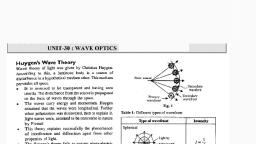
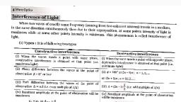
DAY TWENTY NINE, , , , Wave Optics, , Learning & Revision for the Day, , + Wavefront + Young's Double Slit Experiment| + Diffraction, + Huygens’ Principle + Coherent Sources + Polarisation of Light, + Interference of Light + Interference in Thin Films + Brewster's Law, , + Polaroids, , According to Huygens’, light isa form of energy, which travels in the form of waves, through a hypothetical medium ‘ether’, The medium was supposed to be all pervading,, transparent, extremely light, perfectly elastic and an ideal fluid., , Light waves transmit energy as well as momentum and travel in the free space with a, constant speed of 3 x 10° ms~?. However, in a material medium, their speed varies from, medium to medium depending on the refractive index of the medium., , Wavefront, , A wavefront is the locus of all those points (either particles) which are vibrating in the, same phase. The shape of the wavefront depends on the nature end dimension of the, source of light., , , , * In an isotropic medium, for a point source of light, the wavefront is spherical in nature., , , , * Fora line (slit) source of light, the wavefront is cylindrical in shape., © Fora parallel beam of light, the wavefront is a plane wavefront., , Huygens’ Principle, , Every point on a given wavefront, acts as secondary source of light and emits secondary, wavelets which travel in all directions with the speed of light in the medium. A surface, touching all these secondary wavelets tangentially in the forward direction, gives the new, wavefront at that instant of time., , Laws of reflection and refraction can be determined by using Huygens’ principle., , Interference of Light, , Interference of light is the phenomenon of redistribution of light energy in space when, two light waves of same frequency (or same wavelength) emitted by two coherent, sources, travelling in a given direction, superimpose on each other. If a, and a, be the, amplitudes of two light waves of same frequency and 6 be the phase difference, between them, then the amplitude of resultant wave is given by, , , , An, , , , igi, MIRROR, , Your Personal Preparation Indicator, , No. of Questions in Exercises (x)—, No. of Questions Attempted (yj—, , No. of Correct Questions (z}—, , 4 Explanations), , Accuracy Level (z/y x 100)—, Prep Level (z/x x100)—
Page 2 :
316 40 DAYS ~ NEET PHYSICS, , and in terms of intensity of light,, Ip =1, + Iz + 2Tjh; cos 6., , Condition for Constructive Interference, , If at some point in space, the phase difference between, two waves, =0° or 2nn or path difference between two, waves, A=Oor mA, where nis an integer, then Ap =a, +, or I, =1, +1, +211, is maximum. Such an interference is, , called constructive interference., , Condition for Destructive Interference, If at some point in space, the phase difference between two, , waves, } = (2n—1)x or path difference, Aé = (2n — v4 , then at, , such points Ag =(a,—@) and Ip =1, + 1, -2yTjh is, minimum leading to a destructive interference., , Amplitude Ratio, , Tenax., , Tx + +2 _[ V+ vh, Tnm +h -2VQE [Vi - Jk, Tota? [raat, , oo a,| “[r-1], , = amplitude ratio., , , , , , where, r =, , NOTE « For identical sources; ; = 15 =1p, , 29, , * For constructive interference, Imax = 4lg and | = 4/cos* 5, , * For destructive interference, /,,i, = 0, , Young’s Double Slit Experiment, , The arrangement of young’s double slit experiment is shown, , in figure. Here monochromatic light of one wavelength is used., , , , Bright and dark fringes are formed on the screen with central, point O be having as the central bright fringe, because for O,, the path difference A =0., , For light waves reaching a point P, situated at a distance x, from central point A, the path difference,, , A =5,P-S,p=*2, , Case | wd = na, then we get nth bright fringe. Hence,, , position of bright fringes on the screen are given by the, , relation, x = 22&, “"d, , DAY TWENTY NINE, , Case Il wad =(2n-1) 4 then we get nth dark fringe., , (2n-1) DA, , Hence, for nth dark fringe, x = od, , where, n= 1, 2,3, ...... ., , Fringe Width, The separation between any two consecutive bright or dark, fringes is called fringe width B., Dir, a’, and for a given arrangement, it is constant, i.e. all fringes are, uniformly spaced., Moreover, fringe width B is, , Thus,, , (i) B&D, (ii) Be A and (iii) Be 5, Angular fringe width of interference pattern,, BLA, “Dd, , If in a given field of view ny, fringes of light of, wavelength 2, are visible and n, fringes of wavelength A, are, visible, then 1,2; = mz, , NOTE > If whole apparatus of Young's double slit experiment is, immersed in a transparent medium of refractive index Mp,, then fringe width in the medium, B,,,, , , , , , a], , Coherent Sources, , Two light sources are said to be coherent, if they emit light of, exactly same frequency (or wavelength), such that the, originating phase difference between the waves emitted by, them is either zero or remains constant. For sustained, interference pattern, the interfering light sources must be, coherent one., , There are two possible techniques for obtaining coherent, light sources., , * In division of wavefront technique, we divide the, wavefront emitted by a narrow source in two parts by, reflection, refraction or diffraction., , * In division of amplitude technique, a single extended light, beam of large amplitude is splitted into two or more waves, by making use of partial reflection or refraction., , Nore ” Two independent sources of light can never be coherent., “== Two light sources can be coherent only, if these have been, derived from a single parental light source., , Interference in Thin Films, , In white light thin films, whose thickness is comparable to, wavelength of light, show various colours due to interference, of light waves reflected from the two surfaces of thin film.
Page 3 :
DAY TWENTY NINE, , For interference in reflected light condition of constructive, interference (maximum intensity),, , a, A= 21g t cos 7 =(2n~1) =, Condition of destructive interference, (minimum intensity),, a, A= 2g, t cos 7 =(2n) >, For interference in refracted light condition of constructive, interference (maximum intensity),, A=2ngf cos r= en, Condition of destructive interference (minimum intensity),, , d where =1,2, 3p. +, , A=2n,zt cos reat),, , Shift in Interference Pattern, , If a transparent thin sheet of thickness t and refractive index, NM», is placed in the path of one of the superimposing waves, (say in front of slit S of Young's double slit experiment), then, it causes an additional path difference due to which, interference pattern shifts., , * Additional path difference due to sheet =(n,, — 1)t, , i in- fi A FA Ah, Fringe shift = (iy, Df == (ty = Dt, , If due to presence of thin film, the fringe pattern shifts by n, fringes, then, nan = Dt, a, mh, (n, - 1), , Shift is independent of the order of fringe and wavelength., , , , or, , , , NOTE * Fresnel's biprism is a device to produce coherent sources, by division of wavefront,, d=2a(n-1)a, The distance between the coherent sources and screen,, D=a+b, The fringe width is given by B = 2% =A(a+ 6), d 2a(n-1a, , Diffraction, , Diffraction of light is the phenomenon of bending of light, around the edges of an aperture or obstacle and entry of light, even in the region of geometrical shadow, when size of, aperture or obstacle is comparable to wavelength of light, used., , Diffraction is characteristic of all types of waves. Greater the, wavelength, more pronounced is the diffraction effect. It is, , due to this reason that diffraction effect is very commonly, observed in sound., , WAVE OPTICS 317, , Diffraction due to Single Slit and, Width of Central Maximum, , Fraunhofer’s arrangement for studying diffraction at a single, narrow slit (width = a) is shown in adjoining figure. Lenses L,, and L, are used to render incident light beam parallel and to, focus parallel light beam., , , , , , , , , , , , , , We, , \, , 5 ], a, , , , Slit e SSreen, As a result of diffraction, we obtain a broad, bright maxima at, symmetrical centre point O and on either side of it, we get, secondary diffraction maxima of successively falling intensity, and poor contrast, as shown in figure., , !, , ve On Sy (rx) +ve, , Condition of diffraction minima is given by, asin @=na, where, n= 1, 2,3, 4,...., But the condition of secondary diffraction maxima is, , asin =@n+1)%, , where, n= 1,2,3, 4..., , Angular position of nth secondary minima is given by, , sin@=0=n, a, , _nDi _ mfr, a a, , and linear distance, x, = D@, , where, f, is focal length of lens I, and D = fy., , Similarly, for nth maxima, we have, , (2n+1)ar andixs= (2n+1) DA _@n+ 1) fr, 2a 2a 2a, , sin@ =0=, , 2n, , The angular width of central maxima is 20 =“, 2Dh _2f2, , or linear width of central maxima —20N =2hh, , a, , NOTE + The angular width of central maxima is double as compared, to angular width of secondary diffraction maxima.
Page 4 :
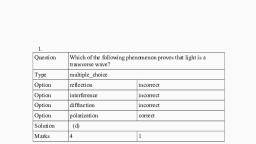
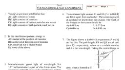
318 40 DAYS ~ NEET PHYSICS, , Polarisation of Light, , © Light is an electromagnetic wave in which electric and, magnetic field vectors very sinusoidally, perpendicular to, each other as well as perpendicular to the direction of, propagation of wave of light., , * The phenomenon of restricting the vibrations of light, (electric vector) in a particular direction, perpendicular to, the direction of wave motion is called polarisation of light., The tourmaline crystal acts as a polariser., , , , , , Polarisation of Light, , Thus, electromagnetic waves are said to be polarised when, their electric field vector are all in a single plane, called the, plane of oscillation/vibration. Light waves from common, sources are upolarised or randomly polarised., , Plane Polarised Light, , The plane ABCD in which the vibrations of polarised light are, confined is called the plane of vibration. It is defined as The, light, in which vibrations. of the-light-(vibrations.of electric, vector) when restricted to a particular plane the light itself is, called plane polarised light. The vibrations in a plane, polarised light are perpendicular to the plane of polarisation., , NOTE + Only transverse waves can be polarised. Thus, it proved, that light waves are transverse waves, , Brewster's Law, , According to this law, when unpolarised light is incident at an, angle called polarising angle, i, on an interface separating air, from a medium of refractive index u, then the reflected light is, , DAY TWENTY NINE, , fully polarised (perpendicular to the plane of incidence),, provided, , = tani,, This relation represents Brewster's law. Note that the parallel, components of incident light do not disappear, but refract into, the medium, with the perpendicular components., , Law of Malus, , When a beam of completely plane polarised light is incident, on an analyser, the resultant intensity of light (I) transmitted, from the analyser varies directly as the square of cosine of, angle (@) between plane of transmission of analyser and, polariser., , ie. I cos? @, , If intensity of plane polarised light incidenting on analyser is, Io, then intensity of emerging light from analyser is Ig cos” @., , NOTE »* We can prove that when unpolarised light of intensity /,, gets polarised on passing through a polaroid, its intensity, , becomes half, ie. / = 3 hy., , Polaroids, , Polaroids are thin and large sheet of crystalline polarising, material (made artifically) which are capable of producing, plane polarised beams of large cross-section., , The important uses are, , © These reduce excess glare and hence sun glasses are fitted, with polaroid sheets., , ¢ These are also used to reduce headlight glare of cars., , * They are used to improve colour contrast in old oil, paintings., , ¢ In wind shields of automobiles., , In window panes., , ¢ In three dimensional motion pictures., , FOUNDATION QUESTIONS EXERCISE, , 1 Two coherent monochromatic light beams of intensities /, and 4/ are superposed. The maximum and minimum, possible intensities in the resulting beam are, , (a)S/and/ = (b)5/and3/ (c)9/and/ = (d) 9/and 3/, , 2 If the equations of two light waves are y, = 8 sinwt and, Yo =6sin (wt + o). Then, ratio of maximum and minimum, intensity will be, , (a) 11: 49, (c)7:1, , (b) 49:1, (d) 1:7, , 3 The ratio of intensity at the centre of a bright fringe to the, intensity at @ point distance one-fourth of the distance, between two successive bright fringes will be, , (a)4 (b) 3 (c)2 (d)1, , 4 Amixture of light consisting of wavelength 590 nm and, an unknown wavelength illuminates Young's double slit, and gives rise to two overlapping interference patterns, on the screen. The central maximum of both light, coincide. Further, it is observed that the third bright
Page 5 :
DAY TWENTY NINE, , fringe is known light coincides with the 4th bright fringe of, an unknown light. From this idea, the wavelength of an, unknown light is, , (a) 885.0nm (b)442.5nm (c)776.8nm (d)393.4nm, , 5. In a Young's experiment, two coherent sources are, placed 0.90 mm apart and the fringes are observed one, metre away. If it produces the second dark fringe at a, distance of 1 mm from the central fringe, then wavelength, of monochromatic light used would be, , (a) 60x 10cm (b) 10x 10cm, (c)10x 10m (d) 6x 10°om, , 6 In the given figure, O’ is the position of first bright range, towards right from OP is the position of 5th bright fringe, on the other side of O with respect to O’. If wavelength of, used light is 6000 A, then value of S,B will be, , , , (a)2.4x 10⁴m, (c)2.4x10%m, , (b)2.4x 10²m, (d)2.4x10%m, , 7 Anarrow slit S transmitting light of wavelength A. is, placed a distance d above a large plane mirror as, shown. The light;coming directly from the:slit-and that, after reflection interfere at P on the screen placed ata, distance D from the slit. What will be x, for which first, maxima occurs?, , a3?, , i, , —— 9, , , , 4d AD 2d D, (a) — ‘b) — (Cc) — ‘d) —, @>5 Oa OF oe, 8 In the Young's double slit experiment, the intensity of, light at a point on the screen, where the path difference, , in 2. is K(A being the wavelength of light used). The, intensity at a point, where the path difference is r will be, , > CBSE AIPMT 2014, , (ak 4 os (a) zero, , 9 The Young's double slit experiment is performed with, blue and with green light of wavelengths 4360 A and, 5460 A, respectively. If x is the distance of 4th maxima, from the central one, then, , (8) Xue = Xoreen, (C) Xue < Xoreen, , () Xue > Noreen, (A) Xue / Green = 5460/ 4360, , WAVE OPTICS 319, , 10 Two slits in Young's experiment have widths in the ratio, 1: 25. The ratio of intensity at the maxima and minima in, , the interference pattern rox is, , Irn > CBSE AIPMT 2015, 9 121, a) = b) =, On. 8, Cc) — (d) —, a5 Os, , 11 |n Young's double slit experiment, when wavelength used, is 6000 A and the screen is 40 cm from the slits, the, fringes are 0.012 cm wide. What is the distance between, the slits?, , (a) 0.024 cm (b) 2.4m, (c) 0.24 cm (d)0.2cm, , 12 \|n Young's double slit experiment using sodium light, (4 = 5898 A), 92 fringes are seen. If given colour, (4 = 5461A) is used, how many fringes will be seen?, , (a) 62 (b) 67, (c) 85 (d) 99, , 13 |n Young's experiment, two coherent sources are, 0.90 mm apart and fringes are observed at a distance, of 1 m, if 2nd dark fringe is at 1 mm distance from, central fringe, then wavelength of the monochromatic, , light will be, (a)60.x.10em (6)10x10em, (c)10x 10%em (d) 6x 10°8cm, , 14 |n Young's double slit experiment, the spacing between, the slits is d and wavelength of light used is 6000 A. If the, angular width of a fringe formed on a distant screen is 1°,, then value of dis, , (a) 1mm (b) 0.05 mm, (c) 0.03 mm, (d) 0.01 mm., , 15 \n Young's double slit experiment, the slits are 2 mm apart, and are illuminated by photons of two wavelength, 4 =12000A and 4 = 10000 A. At what minimum distance, from the common central bright fringe on the screen 2cm, from the slit will a bright fringe from one interference pattern, , coincide with a bright fringe from the other? — + NEET 2013, (a)8mm (b) 6mm, (c)4mm (d) 3mm, , 16 Young's double slit experimental arrangement is as, shown in figure. If 4 is the wavelength of light used and, ZS,CS> = 8, then the fringe width will be, , , , a a 2a, (a) a > (c) 20 (d) =
 Learn better on this topic