Notes of ME3K- 313310 TEG, Thermal engineering THERMAL ENGG UNIT 5 CONDENSER AND COOLING TOWER sma.pdf - Study Material
Page 1 :
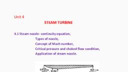
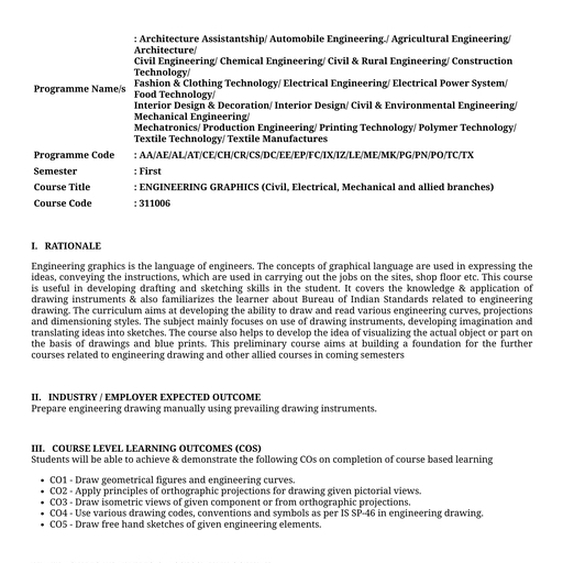
Unit – 5, , Condenser and Cooling Tower., Contents:, 5.1 steam condensers, , , , , Dalton’s Law of Partial Pressure, Introduction- Necessity of Condensers, Classification of Steam Condensers, Construction and working of surface and jet condensers., , 5.2 condenser performance Sources of Air in the Condenser, Condenser Vacuum, Vacuum Efficiency of Condenser, Condenser Efficiency, Cooling Water Requirements for Condenser, Capacity of Air Extraction Pumps Used in Condenser, 5.3 Cooling tower……., Function of Cooling Towers in Condenser, Construction and working of natural, forced and induced, cooling towers., Dalton’s Law of Partial Pressure:, This law states that “Total pressure exerted by mixture of gases, or mixture of gas (air) and vapour (steam) is equal to the sum, of partial pressure of constituents, if they would occupy the, same volume and are at the same temperature”., ∴ Pressure of mixture in condenser = Partial pressure of steam, + Partial pressure of air.
Page 2 :
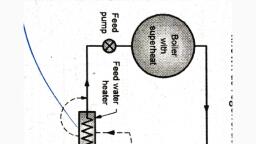
Pc = P s + P a, If the condenser temperature is known, Ps is found from steam, tables and Pc can be read from the vacuum gauge., ∴ We can write, Pa = Pc – Ps, Knowing the partial pressure of air Pa its mass ma can now be, calculated with the help of ideal gas equation, PaVc = maRTa, where Vc = volume of condenser; Ta = temperature; R =, characteristic gas constant of air., Also note that – Each constituent is considered to occupy, condenser volume Vc., , 1. Introduction- Necessity of Condensers:, Steam will be generated in the boilers, after it is being, superheated; it is expanded in the turbines for generating, power. After generating the power, it is either exhausted into, the atmosphere or it is exhausted into the condenser. In the, condensers this steam will be condensed i.e., its phase will be, changed from vapour to liquid by means of cooling water.
Page 3 :
Figure 21.2 shows the theoretical indicator diagram for the, steam turbine., Let the steam available in the turbine have the initial condition, of pressure P1 and temperature T1. This steam is expanded in, the turbines along 2 – 3 for generating work output and then it, is exhausted into the atmosphere along 3 – 4 (slightly above, atmospheric pressure). Let the final condition of steam be, Pb and temperature T2. Then the work output is given by the, area 1 – 2 – 3 – 4 – 1 on the indicator diagram., , According to Carnot’s maximum efficiency of any heat engine, cycle is given by ƞcarnot = (T1 – T2)/T1., From this equation it is clear that the efficiency can be, increased either by increasing T1 or by decreasing T2., In the case of IC engines, efficiency is increased by increasing, T1. (In this case T1 is temperature of products of combustion in, the engine cylinder). When T1 is increased, then the metals, which can withstand high temperature stresses are to be used, in the construction of piston, cylinder, cylinder head etc., even, though they are costly., Whereas in case of external combustion engines, efficiency will, be increased by decreasing T2. By the properties of steam to, obtain lower temperature than T2, lower pressure has to be, created. When the pressure of exhaust steam is lowered
Page 4 :
below Pb, (or atmospheric pressure) steam cannot be, exhausted into the atmosphere. So, it has to be exhausted, into a vessel which is at a lower pressure than Pb and this, vessel is called as the condenser., So, condenser is a device which condenses the exhaust steam, and creates partial vacuum for the steam below atmospheric, pressure. The phenomenon used in the working of the, condensers is that, the volume of steam drops down heavily if it, is condensed and creates a vacuum. For example- 1 kg of, steam at 0.1 bar pressure occupies 14.93 m3 while its, condensate occupies only 0.001076 m3., Thus, by installing the condenser it is possible to reduce the, exhaust steam temperature from T2 to T’2 where T’2 is the, saturation temperature of steam corresponding to condenser, pressure P’b. Now as shown in P – V diagram, work done in a, condensing plant is given by the area 1 – 2 – 6 – 5 – 1., Thus, there is an increase in account of work by 3 – 4 – 5 – 6, by using a condenser. Consequently the thermal efficiency of, the condensing unit will be higher than non- condensing unit. If, the condensate is pure, then it can be used as feed water to the, boiler. This recovery of feed water is also an incidental, advantage., , 2. Classification of Steam Condensers:, Steam condensers are broadly classified as:, I. Jet Condensers:, (a) Low Level Jet Condensers –, (i) Counter-Flow Type, ii) Parallel-Flow Type, (b) High Level Jet Condensers, (c) Ejector Condensers, II. Surface Condensers:, (a) Steam flowing through the tubes and water from outside, (b) Water flowing through the tubes and steam from outside
Page 5 :
(c) Evaporative condensers, What is Jet Condenser, Jet condenser is a mixing type condenser where exhaust steam is, condensed mix up with cooling water. In a jet condenser, high power is, required for condensation. Design of jet condenser is simple. But after, condensation, cooling water cannot be used to boiler as it is not free from, salt and other impurities. So good quality water is used in jet, condenser for condensation., Advantages and Disadvantages Of Jet Condenser, , Advantages Of Jet Condenser:1. Design of the jet condenser is simple., 2. Less floor area is required as compared to the other condenser., 3. Price is cheap of this condenser., Disadvantages Of Jet Condenser:1. Vacuum efficiency is low., 2. Pure condensation is not possible. So it can't be reused., Different Types of Jet Condenser, According to the direction of flow and arrangement of tubing system, mainly, four types of jet condenser is used., 1. Parallel flow jet condenser, 2. Counter flow or low level jet condenser, 3. Barometric or high level jet condenser, 4. Ejector condenser, , 1. Parallel-Flow Jet Condenser
Page 6 :
Parallel flow jet condenser, , As you see in the diagram, exhaust steam, and cooling water, enter the top of the parallel jet condenser and mix up together, in the condenser shell. This mixture is removed from the bottom, of the condenser., Actually, in the condenser, exhausted steam is condensed after, mix up with water. The condensate cooling water and air flow's, direction is downwards of the condenser and it is separated by, two individual pumps which are air pump and condensate, pump., A single way air pump is sometimes used for this separation. At, the time of separation, a vacuum is created in the condenser, chamber. Condensate extraction pump delivers the condensate, to the hot well where an overflow pipe is connected to the, cooling water tank where surplus water of hot well is stored.
Page 7 :
2. Counter-Flow or Low Level Jet Condenser, , Barometric or high level jet condenser, , Counter-Flow or Low Level Jet Condenser, In counter flow or low-level jet condenser, exhaust steam, enters lower side and cooling water comes upper-side of the, condenser chamber, see in the diagram., The direction of exhaust steam is upper-side and cooling water, is downwards. Air pump has created a vacuum and it is placed, at the top of the condenser shell.
Page 8 :
The vacuum draws the supply of the cooling water which falls a, large number of jets. A perforated conical plate stores this, falling water, from which it escapes in second series of jets and, meets the exhaust steam entering at the bottom. Condensate, and cooling water released for this rapid condensation to, discharge the hot well through a vertical pipe by condensate, pump., , 3. Barometric or High-Level Jet Condenser, , Barometric or high level jet condenser, , In barometric or high-level jet condenser, a long discharge tube, is attached to the lower side of the condenser shell, see in the, diagram. Condenser shell arrangement of this type is same as, the low-level jet condenser.
Page 9 :
Exhaust steam enters to the lower side of the condenser and, direction of steam flow is upward direction. Cooling water also, enters from upwards of the shell and stored at perforated, conical plate. Vacuum is created by air pump, placed at the top, of the condenser shell., Now steam and cooling water mix up together and discharge, hot well through a discharge pipe placed at the bottom of the, condenser shell., There is no pump attached in between hot well and discharge, pipe., The surplus water store in a cooling tank through an overflow, pipe., , 4. Ejector Condenser
Page 10 :
Ejector Condenser, , In ejector-type condenser, steam and water mix up, simultaneously and pass through a series of metal, cones., A non-return valve arrangement is arranged for entering, the exhaust steam in the condenser shell., Water enters at the top through a number of guide, cones. Steam and air pass through the hollow truncated, cones. In the cone, kinetic energy is partly transformed, to pressure energy. The condensate and discharge to, the hot well., What is Surface Condenser?, Working principle of surface condenser is completely different, from jet condenser. In surface condenser exhaust steam and, cooling water does not mix up with each other. So condensate, remains pure and can be reused in the boiler., Surface condenser is widely used where limited quantity of, water is available like ship, land installation etc. To use such a, condenser, limited quantity of water feed to the boiler again and, again., In the diagram below, we can see the cylindrical shape surface, condenser which is made off cast iron. In the condenser, some, vessel packed with water tubes. Two vertical perforated tubes, are placed two sides of the condenser and water tubes are, fixed with these plates., In the tube, water flows from one direction to another direction., Cooling water flows in one direction to through the lower half of, the tubes and returns in opposite direction through the upper, half of the tubes.
Page 11 :
SURFACE CONDENSER, Advantages and Disadvantages Of Surface Condenser, , Advantages Of Surface Condenser:1. Pure condensation is possible by the surface condenser., 2. Low quality cooling water can be used for condensation., 3. High vacuum efficiency., Disadvantages Of Surface Condenser:-, , 1. Large floor area is required., 2. Large amount of water is required., 3. Construction is not simple., 4. It's need to be operate by the skilled labour., 5. Maintenance cost is high., , Types Of Surface Condenser, According to the direction of flow and arrangement of tubing system, types, of surface condenser can be classified the following four categories.
Page 12 :
1. Down flow surface condenser, 2. Central flow surface condenser, 3. Regenerative surface condenser, 4. Evaporative surface condenser, , 1. Down flow surface condenser, Figure 21.8 shows the end view of the down flow surface, condenser. In this case baffles are provided throughout the, length of the condenser. It consists of two pumps, one is for, removing the condensate and other is the air pump. In this case, mixed with any air enters from top and descends down as, shown by arrows., The steam when comes in contact with the cold surfaces of, tubes it gets condensed and the air gets cooled. Air is further, cooled when it flows from below the baffle. So the air is cooled, to the minimum temperature before it is extracted. Due to this, cooling of air, its specific volume will be reduced, so it reduces, the pump capacity. So, it reduces the energy consumption for, running the air pump., , Exhaust steam, , Through tubes, cooling water is, flowing
Page 13 :
2. Central flow surface condenser, Figure 21.7 shows the end view of central flow surface, condenser. In this case, air extraction pump is provided at the, centre. So, negative pressure will be created at the centre. In, this case, the exhaust steam and any air enters from top and, will be compelled to flow towards the centre as shown., During its flow, it comes in contact with the cold surface of the, water tubes and gets condensed, and the condensate will be, removed by means of condensate extraction pump., , 3. Regenerative surface condenser, In regenerative surface condenser, regenerative method is, used for condensation. The condensate after leaving the tubes, is passed through the exhaust steam from the turbine. It, improves its temperature for use as feed water for the boiler.
Page 14 :
4. Evaporative surface condenser, When the supply of cold water is extremely limited, then the, evaporative condenser is used since it uses very small amount, of circulating and make up water (since the coolant is used, again and again)., However these condensers are used with small power plants., In this case the exhaust steam from the steam engine enters, into a coil of grilled pipes or series of tubes, the outlet of which, is connected to the wet air pump., The water which is pumped up by means of a pump is sprayed, from the top and descends down. The water falling downwards, forms a thin film over the pipes as it falls from one level to, another and remainder water will be collected in the water tank., A natural or forced air current causes rapid evaporation of this, film of water. The rapid evaporation of film of water results into, condensation of steam. The evaporated vapour will be removed, by means of air., , The main difference between the Jet condensers, and Surface condensers is as given below:, Jet condensers, , Surface condensers, , 1. Steam to be condensed, directly mixes with the, cooling water., , 1. The steam to be condensed, and the cooling water are, separated by means of a, tube well and through which, heat transfer takes place., , 2. Less amount of water is, used., , 2. The amount of cooling water, required will be more., , 3. the temperature of, condensate and cooling, water are same., , 3. Temperature of condensate, will be more than the, temperature of cooling water, at the outlet.
Page 15 :
Jet condensers, 4. The condensate collected, will be impure. (Since the, steam and cooling water, mix with each other)., it has to be wasted., 5. space required and cost of, jet condenser is less, as it, has to handle less quantity, of water., , Surface condensers, 4. It is pure and can be used as, a feed water to the boiler., , 5. space required and cost of, surface condenser is more,, because it has to handle, large quantity of water for the, same capacity., , Sources of Air in the Condenser:, The sources of air in the condenser are as follows:, 1. Leakage through packing glands and microscopic holes in, shell joints since the pressure inside the condenser is less, than the atmospheric pressure., 2. Leakage through relief valves and other accessories., 3. Feed water contains dissolved air, which is liberated in the, boiler during steam formation the exhaust steam from the, steam engine carries air., 4. In case of jet condenser some air comes in with the, injection/cooling water (in which it is dissolved).
Page 16 :
Following are the effects of air, leakage in condenser on its, performance:, 1. Back pressure in the steam power plant increases and, corresponding work output decreases and the very, purpose of using the condenser is defeated., 2. Due to poor thermal conductivity of air, rate of heat, transfer is low therefore more cooling water is required to, be supplied., 3. For maintaining the required vacuum, the air pump is to be, provided., , Condenser Vacuum:, The vacuum in the condenser is usually expressed in mm of, Hg. The absolute pressure in the condenser is equal to the, difference of barometric pressure and the vacuum pressure as, shown in Fig. 21.10., Absolute pressure in the condenser = (barometric pressure vacuum pressure)
Page 18 :
Vacuum Efficiency of Condenser:, It may be defined as the ratio of actual vacuum as recorded, by the vacuum gauge to the ideal vacuum., , Condenser Efficiency:, There is no standard method of determining the condenser, efficiency but a method adopted by the well-known makers of, steam turbine M/s Parson & Co. has been widely used in, engineering practice.
Page 19 :
Cooling Water Requirements for Condenser:, In a condenser, cooling water absorbs heat from steam to be, condensed and the temperature of cooling water increases. In, jet condensers steam to be condensed directly mixes with, cooling water and hence temperature of condensate and, cooling water are same.
Page 20 :
Capacity of Air Extraction Pumps Used in Condenser:, We know that, absolute pressure in the condenser –
Page 22 :
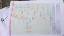
Cooling Towers:, Function of Cooling Towers in Condenser:, The function of the cooling tower is to cool the cooling water of, the condenser, by the current of air flowing in the opposite, direction., A large amount of cooling water is required for condensation in, large capacity power plants. If the water is freely available, either from the river or lake, then the water can be directly, pumped from the river to the condenser as shown in Fig. 21.13, (a)., If the water is not freely available, then a cooling tower has to, be used for cooling the hot water of condenser., The cooled water can be used again as cooling water for the, condenser., Figure 21.13 (b) shows the hyperbolic cooling tower. It is, usually made of steel Reinforced cement concrete. The hot, water from the condenser is supplied to the ring troughs which, are placed at 8-10 m above the ground level. The nozzles are, provided on the bottom side of troughs to break up water into, sprays., The air rises up from the pond in the opposite direction of water, flow and absorbs heat from the falling water spray. The cooled, water is collected into a pond built below the tower. This type of, cooling tower is generally used since it is very efficient;, however, it needs about 3-5 % of makeup water for, compensating the evaporation losses.
Page 23 :
The other types of cooling towers are:, (i) Natural Draught Towers:, In this type the circulation of air is obtained by virtue of, pressure difference of the air inside and outside the tower. Here, no fan is required.
Page 24 :
Natural draft, , (ii) Forced Draught Tower:, In this case, the circulation of air is obtained by means of fans, provided at the bottom of the tower.
Page 25 :
FORCED DRAFT, , (iii) Induced Draught Tower:, In this case, the circulation of air is obtained by providing a fan, at the top of the tower., , ===xxx==
 Learn better on this topic