Notes of APNA TECHNICAL CLASSES, Advance Surveying@4th Sem unit 1 - Study Material
Page 1 :
APNA TECHNICAL CLASSES, DEPARTMENT OF CIVIL, SEMESTER :- 4TH, SUBJECT :- ADVANCE SURVEYING (1615401), UNIT :- 1, , PLANE TABLE SURVEYING, , Don’t compare yourself with others, no one can play your, role better than you
Page 2 :
➢ ADVANCE SURVEYING, UNIT- 1, UNIT – 2, UNIT -3, UNIT -4, UNIT -5, UNIT -6, , PLANE TABLE SURVEY, THEODOLITE SURVEY, TACHEOMETRIC SURVEY, CURVES, ADVANCED SURVEY EQUIPMENT, AERIAL SURVRY AND REMOTE SENSING
Page 3 :
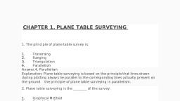
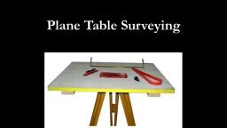
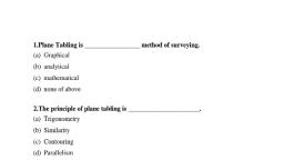
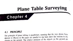
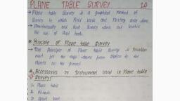
PLANE TABLE SURVEY, Plane tabling is the graphical method of survey in which the field work /, application and plotting are done simultaneously, , In plane table survey the field work is not required and easy to do survey, PRINCIPLE OF PLANE TABLE SURVEY, The principle of plane table survey is parallism meant the rays drawn from, station to the object on the ground and plotting it on the paper, INSTRUMENTS/EQUIPMENTS USED IN THE PLANE TABLE SURVEY, 1., 2., 3., 4., 5., 6., , PLANE TABLE, ALIDADE, SPRITE LEVEL, TROUGH COMPASS, U-FORK OR PLUMBING FORK, DRAWING PAPER WITH A RAIN PROOF COVER
Page 4 :
1 PLANE TABLE, , The plane table is the drawing board of size 750mm*600mm made by the seasold wood ., The top surface of the table is well levelled and the bottom surface consist of a threaded, circular plate for fixing the table on the tripoded stand by a wing nut, It is used for fixing a drawing sheet over it . The position of the object are located on this, sheet by drawing rays and plotting to any suitable scale., Traverse table, johnson table & coast survey table are the main type of the plane table in, which johnson table is mostly used, A the traverse table, B johnson table (450mm*600mm or 600mm*750mm), C the coast survey table
Page 7 :
PLANE ALIDADE, The plane alidade consist of a metal or wooden roller of length about 50cm, It consist of two vanes at the both ends which are hinged with roller, , TELISCOPIC ALIDADE, It consist of telescope and it is used for inclined sight and sighting the, distance of object clearly, The alidade has no vane at the ends, The rays drawn on the table with the help of alidade
Page 8 :
3 SPRIT LEVEL, The sprit level is the small metal tube containing a small bubble tube . Sprit, level is used for levelling the plane table, , The bubble is visible on the top along the graduated glass tube
Page 9 :
4 TROUGH COMPASS, , It is a rectangular box made up, of the non magnetic metal, containing a magnetic needle, pivoted at the centre, The compass consist of a zero, mark at the both ends to locate, the north south direction, It is mainly used for marking, the north direction on the map
Page 10 :
5 u- FORK OR PLUMBING FORK, It is made up of the metal strip which is bent in U- shape having equal arm, length, It is used for centring the table over the station at ground, The top arm is pointed and the bottom arm carries a hook for suspending a, plum bob
Page 11 :
SETTING OUT THE PLANE TABLE, 1., 2., 3., 4., 5., , Fixing the table on the tripoded stand, Levelling the table, Centring the table, Marking the north line, Orientation, , 1 FIXING THE TABLE ON THE TRIPODED STAND, A tripoded stand is kept on the ground and the plane table is kept, on it and fixing by wing nut.
Page 12 :
2 LEVELLING THE TABLE, the table is levelled by placing the sprit level at the different corner and the, various position on the table, The bubble right to the centre of its run at every position of the table by, adjusting the legs, 3 CENTRING THE TABLE, , The drawing paper is fixed on the table., A suitable point p is selected on the sheet to represent the station P on the, ground
Page 13 :
Then a pin is fixed on the selected point p, The upper pointed arm of u- fork is made in contact with the station pin and, the plumb bob which is suspended from the hook at the lower end is, brought just over the station P by turning the table clockwise or, anticlockwise or slightly adjusting the legs this operation is called centring, While cantering the table care must be taken not to disturb the levelling, 4 MARKING THE NORTH LINE, , the trough compass is placed on the right hand top corner with it north end, approximately towards the north, Then the compass is turn clockwise and anticlockwise so that the needle, adjectly conside with zero zero mark
Page 14 :
Now the line representing the north line is drawn through the edge, of compass, 5 ORIENTATION, When the plane table survey is conducted by connecting the several, station , the orientation must be performed at every successive, station, Orientation is done by two method, A. Orientation by back sighting, B. Orientation by trough compass, During the orientation it should always be remember that the, requirement of centring , levelling and orientation must be satisfied, simultaneously
Page 15 :
The back sight always be preferred because it is reliable, ❖ METHOD OF ORIENTATION, , I. Orientation by back sighting, II. Orientation by trough compass, , i., , ORIENTATION BY BACK SIGHTING, , Some important steps which involve in orientation by back sighting, which are as follows:-
Page 16 :
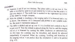
STEP 1 - Suppose A and B Are the two station point. The plane table is, setup at station A the table is levelled by the sprit level and centred, by u- fork, the point ‘a’ just over the point A, The north line is marked on the right hand top corner of the sheet, by trough compass, STEP -2 with the alidade touching the point ‘a’ the ranging rod at B is, bisected and a ray is drawn , the distance AB is measured and, plotted to any suitable scale so that the point ‘b’ represent B., STEP-3 the table is shifted and setup over B it is levelled and centred so, that ‘b’ just over the station B, now the alidade is placed along the line and the ranging rod at A is, bisected by turning the table clockwise or anticlockwise
Page 17 :
At this time centring may be disturb and should be adjusted, immediately if required, when the centring , levelling and the bisection of ranging rod at A, perfect then the orientation is said to be perfect
Page 18 :
|| ORIENTATION BY TROUGH COMPASS, Step-1 suppose A and B are two station point . The plane table setup at, station A . The table is levelled by the sprit level and centred by the, u- fork so that the point ‘a’ just over the station A, , The north line is marked on the right hand top corner of the, sheet by trough compass ., Step -2 with the alidade touching the point ‘a’ and then the ranging rod at, B is bisected and a ray is drawn . AB distance is measured and, plotted to any suitable scale so that, the point ‘b’ represent the, station B
Page 19 :
STEP -3 the trough compass placed adjectly along the north line drawn, previously after shifting the table is turned clockwise and, anticlockwise until the needle conside adjectly with the zerozero mark of the compass, Step 4 when the centring and levelling are perfect and needle is adjectly, at zero- zero, then, the orientation is said to perfect and this process is, repeated over the all station such as A,B,C,D,E,…..etc, Trough compass
Page 20 :
❖METHOD OF PLANE TABLE, 1., 2., 3., 4., , Radiation, Intersection, Traversing, Resection, , The first two methods are generally employed for, locating the details while the other two methods are, used for locating the plane table station, 1 Radiation, This method is suitable for locating the objects from a single station.
Page 21 :
In this method , a ray drawn from the instrument station towards, the point, the distance is measured between the instrument station to, that point , and the point located by plotting to some scale the, distance so measured., , This method is very suitable when the distance are small ( within a, tape length ) and one single instrument control the points to be, detailed., PROCEDURE, 1. Set the table at T, level it and then transfer the point on to the, sheet by means of plumbing fork, thus getting the point ‘t’ on the, sheet represent the station T
Page 22 :
2., , Keep the alidade touching ‘t’ and sight to A . Draw the ray along the, fiducial edge of the alidade, , 3 Similarly, sight different point B,C,D ,E,….etc , and draw the, corresponding rays. A pin may be inserted at ‘t’ and the alidade may, be kept in touching the pin while sighting the point., 4 Measured TA, TB, TC , TD ,TE etc , in the field and plot their distances, to some suitable scale along the corresponding rays., 5 Then getting the points a, b, c, d ,e …etc, on the sheet and join these, if it needed
Page 24 :
2 Intersection, , This method is suitable for locating the inaccessible point by the, intersection of the ray drawn from the two instrument station, PROCEDURE, 1 Suppose A and B are two station point and P is an object on the, bank of the river . Now it is required to fix the position of P on, the sheet by intersecting of ray drawn from A and B, 2 The table is setup at A , it is levelled and centred so that the, point ‘a’ on the sheet just over the station A . The north line also, marked on the sheet
Page 25 :
3. With the alidade touching point ‘a’ and P and ranging rod at B are, bisected and the ray are drawn, 4. The distance AB is measured and plotted to any suitable scale to, obtained the point ‘b’, 5. Then the table is shifted , levelled and centred over the station B, properly now the alidade placed along the line ‘ba’ and orientation is, done by back sighting , at this time it should be remember that, levelling centring and orientation must be perfect simultaneously, , 6. With the alidade touching ‘b’ the object P is bisected and a ray is, drawn suppose this ray intersect the previous ray at point ‘p’ . This, point ‘p is the required position of P
Page 27 :
3 traversing, This method is suitable for connecting the traverse station . This, method is similar to comp[ass traversing or theodolite traversing ,, But in this method field work and plotting are done simultaneously, with the help of reduction and intersection, PROCEDURE, (i) Suppose A,B,C and D are the traverse station, The table is set up at the station A and than the table is centred ,, levelled. The north line is marked on the sheet, (ii) With the alidade touching ‘a’ the ranging rod at ‘b’ is bisected, and the ray is drawn .The distance AB is measured and plotted, to any suitable scale .
Page 28 :
(iii) The table is shifted and centred over the B and then the table i, centred , levelled and oriented, (iv) With the alidade touching ‘b’ the ranging rod at ‘c’ is bisected, and a ray is drawn .The distance BC is measured and plotted to, some scale ., (v) The table is shifted and setup at c and some procedure is, repeated ., (vi) In this way/manner all station if the traverse are connected
Page 30 :
4. Resection, This method is suitable for establishing new station at a plane in, order to locate missing details, • METHOD OF RESECTION, (i) Resection by back sighting, (ii) Resection by compass, (iii) Two point problem, (iv) Three point problem
Page 31 :
❖ Advantage of plane table, i., , it is the most rapid method of surveying, , ii. There is no need for a field book as plotting is done along, with the field work., , iii. The problem of mistake in booking field notes does not arise ., iv. Plotted work can be compared with actual project., , v. There is no possibility of over looking any important object .
Page 32 :
vi. There is no possibility of overt looking any measurement because, plotting is done in field ., It is suitable in magnetic area, The map can prepared easily and dose not required any great skills, In accessible point can be easily located by intersection, ❖ DISADVANTAGE OF PLANE TABLE, (i) The plane table is not suitable for accurate work because the, fitting arrangement is not perfect
Page 33 :
(ii) It is not suitable in rainy season , on foggy morning in windily, weather and in heavy sun light., (iii) The number of accessories required in such survey is large and, they are likely to lost .., (iv) The map can not be replotted to a different scale because there, is not field book., ., , The end
 Learn better on this topic